

baltur BTG 3.6P, BTG 6P, BTG 11P Installation, Use And Maintenance Instruction Manual [it, en]
Page 1

BRUCIATORI A GAS BISTADIO
TWO-STAGE GAS BURNERS
ITALIANO
Manuale istruzioni per l'installazione,
l'uso e la manutenzione
IT
Installation, use and maintenance
instruction manual
EN
BTG 3,6P
BTG 6P
BTG 11P
ISTRUZIONI ORIGINALI (IT)
ORIGINAL INSTRUCTIONS (IT)
0006080763_201611
Page 2

Page 3

ITALIANO
SOMMARIO
Avvertenze per l'uso in condizioni di sicurezza .......................................................................................................................................3
Caratteristiche tecniche ........................................................................................................................................................................... 6
Materiale a corredo ...........................................................................................................................................................................7
Targa identicazione bruciatore.........................................................................................................................................................7
Dati registrazione prima accensione ................................................................................................................................................. 7
Campo di lavoro ................................................................................................................................................................................ 8
Dimensioni di ingombro ..................................................................................................................................................................... 9
Descrizione componenti .................................................................................................................................................................. 10
Applicazione del bruciatore alla caldaia ................................................................................................................................................ 11
Collegamenti elettrici ............................................................................................................................................................................. 12
Descrizione del funzionamento .............................................................................................................................................................13
Accensione e regolazione .....................................................................................................................................................................13
Regolazione aria sulla testa di combustione ................................................................................................................................... 15
Corrente ionizzazione......................................................................................................................................................................15
Apparecchiatura di comando e controllo LME... .................................................................................................................................... 16
SERVOMOTORE COMANDO SERRANDA ARIA CONNECTRON “LKS 120-02 (B5-5-51) ................................................................. 19
Schema di regolazione testa di combustione e distanza disco elettrodi ......................................................................................... 20
Manutenzione ........................................................................................................................................................................................ 23
tempi di manutenzione .................................................................................................................................................................... 24
Precisazioni sull'uso del propano ..........................................................................................................................................................25
Schema di principio per riduzione pressione G.P.L. a due stadi per bruciatore oppure caldaia .....................................................26
SCHEMA DI INSTALLAZIONE CON VAPORIZZATORE ................................................................................................................ 27
Istruzioni per l'accertamento delle cause di irregolarità nel funzionamento e la loro eliminazione........................................................28
Schemi elettrici ...................................................................................................................................................................................... 29
ITALIANO
1 / 30
0006080763_201611
Page 4

DICHIARAZIONE DI CONFORMITÀ
CE0085:
DVGW CERT GmbH, Josef-Wirmer Strasse 1-3-53123 Bonn (D)
Dichiariamo che i nostri bruciatori ad aria sofata di combustibili luquidi, gassosi e misti, domestici e industriali, serie:
BPM...; BGN…; BT…; BTG…; BTL…; TBML...; Comist…; GI…; GI…Mist; Minicomist…; PYR…; RiNOx…; Spark...; Sparkgas...;
TBG...;TBL...; TS…; IBR...; IB...
(Variante: … LX, per basse emissioni NOx)
rispettano i requisiti minimi imposti dalle Direttive Europee:
• 2009/142/CE (D.A.G.)
• 2004/108/CE (C.E.M.)
• 2006/95/CE (D.B.T.)
• 2006/42/CE (D.M.)
e sono conformi alle Norme Europee:
• prEN 676:2012 (gas e misti, lato gas)
• prEN 267:2012 (gasolio e misti, lato gasolio)
• EN 60335-1 (2012-01) + EC (2014-01) (tutti i bruciatori).
Cento, 12 Gennaio 2015
Direttore Ricerca & Sviluppo
Paolo ing. Bolognin
Amministratore Delegato e Direttore Generale
Riccardo dr. Fava
ITALIANO
2 / 30
0006080763_201611
Page 5

AVVERTENZE PER L'USO IN CONDIZIONI
DI SICUREZZA
SCOPO DEL MANUALE
Il manuale si propone di contribuire all'utilizzo sicuro del prodotto
a cui fa riferimento, mediante l'indicazione di quei comportamenti
necessari prevedendo di evitare alterazioni delle caratteristiche
di sicurezza derivanti da eventuali installazioni non corrette, usi
erronei, impropri o irragionevoli.
E’ esclusa qualsiasi responsabilità contrattuale ed extracontrattuale del costruttore per i danni causati da errori nell’installazione
e nell’uso, e comunque da inosservanza delle istruzioni date dal
costruttore stesso.
• Le macchine prodotte hanno una vita minima di 10 anni, se
vengono rispettate le normali condizioni di lavoro ed effettuate
le manutenzioni periodiche indicate dal fabbricante.
• ll libretto di istruzioni costituisce parte integrante ed essenziale
del prodotto e dovrà essere consegnato all’utente.
• L'utente dovrà conservare con cura il libretto per ogni ulteriore
consultazione.
• Prima di iniziare a usare l’apparecchio, leggere attentamen-
te le “Istruzioni per l’uso” riportate nel manuale e quelle
applicate direttamente sul prodotto, al ne di minimizzare i
rischi ed evitare incidenti.
• Prestare attenzione alle AVVERTENZE DI SICUREZZA, non
adottare USI IMPROPRI.
• L'installatore deve valutare i RISCHI RESIDUI che potrebbero
sussistere.
• Per evidenziare alcune parti di testo o per indicare alcune spe-
ciche di rilevante importanza, sono stati adottati alcuni simboli
di cui viene descritto il signicato.
PERICOLO / ATTENZIONE
Il simbolo indica situazione di grave pericolo che, se trascurate, possono mettere seriamente a rischio la salute e la
sicurezza delle persone.
CAUTELA / AVVERTENZE
Il simbolo indica che è necessario adottare comportamenti
adeguati per non mettere a rischio la salute e la sicurezza
delle persone e non provocare danni economici.
IMPORTANTE
Il simbolo indica informazioni tecniche ed operative di particolare importanza da non trascurare.
CONDIZIONI E DURATA DELLO STOCCAGGIO
Gli apparecchi vengono spediti con l'imballaggio del costruttore
e trasportati su gomma, via mare e via ferrovia in conformità con
le norme per il trasporto di merci in vigore per l'effettivo mezzo di
trasporto utilizzato.
Per apparecchi non utilizzati, è necessario conservarli in locali chiusi con la dovuta circolazione d'aria a condizioni standard
(temperatura compresa fra -10° C e + 40° C).
Il preriodo di stoccaggio è di 3 anni.
AVVERTENZE GENERALI
• La data di produzione dell'apparecchio (mese, anno) sono indicati sulla targa identicazione bruciatore presente sull'apparecchio.
• L'apparecchio non è adatto a essere usato da persone (bam-
bini compresi) le cui capacità siche, sensoriali o mentali siano
ridotte, oppure con mancanza di esperienza o di conoscenza.
• l'uso dell'apparecchio è consentito a tali persone solo nel caso
in cui possano beneciare, attraverso l'intermediazione di una
persona responsabile, di informazioni relative alla loro sicurez-
za, di una sorveglianza, di istruzioni riguardanti l'uso dell'apparecchio.
• I bambini devono essere sorvegliati per sincerarsi che non giochino con l'apparecchio.
• Questo apparecchio dovrà essere destinato solo all’uso per il
quale é stato espressamente previsto. Ogni altro uso é da considerarsi improprio e quindi pericoloso.
• L’installazione dell’apparecchio deve essere effettuata in ottemperanza alle norme vigenti, secondo le istruzioni del costruttore
a da personale professionalmente qualicato.
• Per personale professionalmente qualicato si intende quello
avente specica e dimostrata competenza tecnica nel settore,
in accordo con la legislazione locale vigente.
• Un’errata installazione può causare danni a persone, animali o
cose, per i quali il costruttore non é responsabile.
• Dopo aver tolto ogni imballaggio assicurarsi dell’integrità del
contenuto. In caso di dubbio non utilizzare l’apparecchio e rivolgersi al fornitore. Gli elementi dell’imballaggio non devono
essere lasciati alla portata dei bambini in quanto potenziali fonti
di pericolo.
• La maggior parte dei componenti dell'apparecchio si compo-
ne di materiali che possono essere riutilizzati. L'imballaggio e
l'apparecchio non possono essere smaltiti insieme ai normali
riuti domestici, ma sono soggetti a smaltimento conforme alle
normative vigenti.
• Prima di effettuare qualsiasi operazione di pulizia o manutenzione, disinserire l’apparecchio dalla rete di alimentazione
agendo sull’interruttore dell’impianto e/o attraverso gli appositi
organi di intercettazione.
• Se l’apparecchio dovesse essere venduto o trasferito ad un altro
proprietario o se si dovesse traslocare e lasciare l’apparecchio,
assicurarsi sempre che il libretto accompagni l’apparecchio in
modo che possa essere consultato dal nuovo proprietario e/o
dall’installatore.
• Con apparecchio in funzione non toccare le parti calde normal-
mente situate in vicinanza della amma e dell’eventuale sistema di preriscaldamento del combustibile. Possono rimanere
calde anche dopo un arresto non prolungato dell'apparecchio.
• Per tutti gli apparecchi con optionals o kit (compresi quelli elettrici) si dovranno utilizzare solo accessori originali.
ITALIANO
3 / 30
0006080763_201611
Page 6

• In caso di guasto e/o di cattivo funzionamento dell’apparecchio,
disattivarlo, astenendosi da qualsiasi tentativo di riparazione o
di intervento diretto. Rivolgersi esclusivamente a personale pro-
fessionalmente qualicato.
• L’eventuale riparazione dei prodotti dovrà essere effettuata solamente da un centro di assistenza autorizzato da BALTUR o
dal suo distributore locale, utilizzando esclusivamente ricambi
originali.
• Il costruttore e/o il suo distributore locale declinano qualunque
responsabilità per incidenti o danni causati da modiche non
autorizzate sul prodotto o dalla inosservanza delle prescrizioni
contenute nel manuale.
AVVERTENZE DI SICUREZZA PER L’INSTALLAZIONE
• L'apparecchio deve essere installato in un locale idoneo con
una adeguata ventilazione secondo le leggi e norme vigenti.
• La sezione delle griglie di aspirazione dell’aria e le aperture di
aerazione del locale di installazione non devono essere ostruite
o ridotte.
• Il locale di installazione NON deve presentare il rischio di esplosione e/o incendio.
• Prima dell’installazione si consiglia di effettuare una accurata
pulizia interna di tutte le tubazioni dell’impianto di alimentazione
del combustibile.
• Prima di collegare l'apparecchio accertarsi che i dati di targa si-
ano corrispondenti a quelli della rete di alimentazione (elettrica,
gas, gasolio o altro combustibile).
• Accertarsi che il bruciatore sia ssato saldamente al generatore
di calore secondo le indicazioni del costruttore.
• Effettuare gli allacciamenti alle fonti di energia a regola d’arte
come indicato negli schemi esplicativi secondo i requisiti normativi e legislativi in vigore al momento dell’installazione.
• Vericare che l’impianto di smaltimento fumi NON sia ostruito.
• Se si decide di non utilizzare, in via denitiva il bruciatore, si
dovranno far effettuare da personale professionalmente qualicato le seguenti operazioni:
- Disinserire l’alimentazione elettrica staccando il cavo di
alimentazione dell’interruttore generale.
- Chiudere l’alimentazione del combustibile attraverso la
valvola manuale di intercettazione e asportare i volantini di
comando dalla loro sede.
- Rendere innocue quelle parti che potrebbero essere potenziali fonti di pericolo.
AVVERTENZE PER L'AVVIAMENTO IL COLLAUDO L'USO E
LA MANUTENZIONE
• L'avviamento, il collaudo e la manutenzione devono essere effettuati esclusivamente da personale professionalmente qualicato, in ottemperanza alle disposizioni vigenti.
• Fissato il bruciatore al generatore di calore, accertarsi durante
il collaudo che la amma generata non fuoriesca da eventuali
fessure.
• Controllare la tenuta dei tubi di alimentazione del combustibile
all'apparecchio.
• Vericare la portata del combustibile che coincida con la poten-
za richiesta al bruciatore.
• Tarare la portata di combustibile del bruciatore secondo la po-
tenza richiesta dal generatore di calore.
• La pressione di alimentazione del combustibile deve essere
compresa nei valori riportati nella targhetta, presente sul bru-
ciatore e/o sul manuale
• L’impianto di alimentazione del combustibile sia dimensionato
per la portata necessaria al bruciatore e che sia dotato di tutti i
dispositivi di sicurezza e controllo prescritti dalle norme vigenti.
• Prima di avviare il bruciatore e almeno una volta all’anno, far ef-
fettuare da personale professionalmente qualicato le seguenti
operazioni:
- Tarare la portata di combustibile del bruciatore secondo la
potenza richiesta dal generatore di calore.
- Eseguire il controllo della combustione regolando la portata
d’aria comburente e/o del combustibile, per ottimizzare il
rendimento di combustione e le emissioni in osservanza alla
legislazione vigente.
- Vericare la funzionalità dei dispositivi di regolazione e di
sicurezza.
- Vericare la corretta funzionalità del condotto di evacuazio-
ne dei prodotti della combustione.
- Controllare la tenuta nel tratto interno ed esterno dei tubi di
alimentazione del combustibile.
- Controllare al termine delle regolazioni che tutti i sistemi di
bloccaggio meccanico dei dispositivi di regolazione siano
ben serrati.
- Accertarsi che siano disponibili le istruzioni relative all’uso e
manutenzione del bruciatore.
• In caso di ripetuti arresti in blocco del bruciatore non insistere
con le procedure di riarmo manuale, ma rivolgersi a personale
professionalmente qualicato.
• Allorché si decida di non utilizzare il bruciatore per un certo
periodo, chiudere il rubinetto o i rubinetti di alimentazione del
combustibile.
ITALIANO
4 / 30
0006080763_201611
Page 7

Avvertenze particolari per l’uso del gas.
• Vericare che la linea di adduzione e la rampa siano conformi
alle norme e prescrizioni vigenti.
• Vericare che tutte le connessioni gas siano a tenuta.
• Non lasciare l’apparecchio inutilmente inserito quando non è
utilizzato e chiudere sempre il rubinetto del gas.
• In caso di assenza prolungata dell’utente dell’apparecchio chiu-
dere il rubinetto principale di adduzione del gas al bruciatore.
• Avvertendo odore di gas:
- non azionare interruttori elettrici, il telefono e qualsiasi altro
oggetto che possa provocare scintille;
- aprire immediatamente porte e nestre per creare una
corrente d’aria che purichi il locale;
- chiudere i rubinetti del gas;
- richiedere l’intervento di personale professionalmente
qualicato.
• Non ostruire le aperture di aerazione del locale dove é installato
un apparecchio a gas, per evitare situazioni pericolose quali la
formazione di miscele tossiche ed esplosive.
RISCHI RESIDUI
• Nonostante l'accurata progettazione del prodotto, nel rispetto
delle norme cogenti e delle buone regole nell'impiego corretto
possono permanere dei rischi residui. Questi vengono segnalati
sul bruciatore con opportuni Pittogrammi.
ATTENZIONE
Organi meccanici in movimento.
ATTENZIONE
Materiali a temperature elevate.
ATTENZIONE
Quadro elettrico sotto tensione.
AVVERTENZE SICUREZZA ELETTRICA
• Vericare che l’apparecchio abbia un idoneo impianto di messa
a terra, eseguito secondo le vigenti norme di sicurezza.
• Non utilizzare i tubi del gas come messa a terra di apparecchi
elettrici.
• In caso di dubbi richiedere un controllo accurato dell’impianto
elettrico da parte di personale qualicato, in quanto il costruttore non é responsabile per eventuali danni causati dalla man-
canza di messa a terra dell’impianto.
• Far vericare da personale professionalmente qualicato che
l’impianto elettrico sia adeguato alla potenza massima assorbita dall’apparecchio indicata in targa.
• Accertarsi che la sezione dei cavi dell’impianto sia idonea alla
potenza assorbita dall’apparecchio.
• Non é consentito l’uso di adattatori, prese multiple e/o prolunghe per l’alimentazione generale dell’apparecchio alla rete elettrica.
• Prevedere un interruttore onnipolare con distanza d’apertura
dei contatti uguale o superiore a 3 mm per l’allacciamento alla
rete elettrica, come previsto dalle normative di sicurezza vigenti
(condizione della categoria di sovratensione III).
• Per l'alimentazione elettrica del bruciatore utilizzare esclusivamente cavi a doppio isolamento, con isolamento esterno di
almeno 1 mm di spessore.
• Sguainare l’isolante esterno del cavo di alimentazione nella
misura strettamente necessaria al collegamento, evitando così
che il lo possa venire a contatto con parti metalliche.
• L’alimentazione elettrica del bruciatore deve prevedere il neutro
a terra. In caso di controllo della corrente di ionizzazione con
neutro non a terra è indispensabile collegare tra il morsetto 2
(neutro) e la terra il circuito RC.
• In caso di assenza prolungata dell’utente dell’apparecchio chiu-
dere il rubinetto principale di adduzione del gas al bruciatore.
• L’uso di un qualsiasi componente che utilizza energia elettrica
comporta l’osservanza di alcune regole fondamentali quali:
- non toccare l’apparecchio con parti del corpo bagnate o
umide e/o a piedi umidi;
- non tirare i cavi elettrici;
- non lasciare esposto l’apparecchio ad agenti atmosferici
(pioggia, sole, ecc.) a meno che non sia espressamente
previsto;
- non permettere che l’apparecchio sia usato da bambini o da
persone inesperte;
- ll cavo di alimentazione dell’apparecchio non deve essere
sostituito dall’utente. In caso di danneggiamento del cavo,
spegnere l’apparecchio. Per la sua sostituzione,rivolgersi
esclusivamente a personale professionalmente qualicato;
- Allorché si decida di non utilizzare l’apparecchio per un
certo periodo é opportuno spegnere l’interruttore elettrico di
alimentazione a tutti i componenti dell’impianto che utilizza-
no energia elettrica (pompe, bruciatore, ecc.).
ITALIANO
5 / 30
0006080763_201611
Page 8

CARATTERISTICHE TECNICHE
MODELLO BTG 3,6P BTG 6P BTG 11P
POTENZA TERMICA MASSIMA METANO
kW
41.9 56.3 99
POTENZA TERMICA MINIMA METANO
kW
16.3 30.6 48.8
¹) EMISSIONI METANO
mg/kWh
Classe 2 Classe 2 Classe 2
FUNZIONAMENTO Bistadio Bistadio Bistadio
TRASFORMATORE METANO 50 Hz 15kV - 25mA 15kV - 25mA 15kV - 25mA
TRASFORMATORE METANO 60 Hz 15kV - 25mA 15kV - 25mA 15kV - 25mA
PORTATA TERMICA MASSIMA METANO
Stm³/h
4.2 5.7 10
PORTATA TERMICA MINIMA METANO
Stm³/h
1.6 3.1 4.9
PRESSIONE MASSIMA METANO
mbar
360 360 360
PRESSIONE MINIMA METANO
mbar
19 20 20
POTENZA TERMICA MASSIMA PROPANO
kW
41.9 56.3 99
POTENZA TERMICA MINIMA PROPANO
kW
16.3 30.6 48.8
PORTATA TERMICA MASSIMA PROPANO
Stm³/h
1.63 2.2 3.87
PORTATA TERMICA MINIMA PROPANO
Stm³/h
0.64 1.2 1.9
PRESSIONE MASSIMA PROPANO
mbar
360 360 360
PRESSIONE MINIMA PROPANO
mbar
30 30 30
²)EMISSIONI PROPANO
mg/kWh
Classe 2 Classe 2 Classe 2
MOTORE VENTOLA 50Hz
kW
0.11 0.11 0.11
GIRI MOTORE VENTOLA 50Hz
giri/min.
2800 2800 2800
MOTORE VENTOLA 60Hz
kW
0.11 0.11 0.11
GIRI MOTORE VENTOLA 60Hz
giri/min.
3300 3300 3300
POTENZA ELETTRICA ASSORBITA* 50Hz
kW
0.11 0.11 0.11
POTENZA ELETTRICA ASSORBITA* 60Hz
kW
0.11 0.11 0.11
TENSIONE DI ALIMENTAZIONE 50 Hz 1N~ 230V ± 10% 1N~ 230V ± 10% 1N~ 230V ± 10%
TENSIONE DI ALIMENTAZIONE 60 Hz 1N~ 220V ± 10% 1N~ 220V ± 10% 1N~ 220V ± 10%
GRADO DI PROTEZIONE IP40 IP40 IP40
RILEVAZIONE FIAMMA
SONDA DI IONIZZA-
ZIONE
SONDA DI IONIZZA-
ZIONE
SONDA DI IONIZZA-
ZIONE
APPARECCHIATURA LME21.. LME21.. LME21..
PRESSIONE SONORA**
dBA
64 64 64
PESO CON IMBALLO
kg
12 12 12
PESO SENZA IMBALLO
kg
10.75 10.75 10.75
Potere calorico inferiore alle condizioni di riferimento 15° C, 1013 mbar:
Gas metano: Hi = 9,45 kWh/Stm³ = 34,02 MJ/Stm³
Propano: Hi = 24,44 kWh/Stm³ = 88,00 MJ/Stm³
Per tipi di gas e pressioni diverse, consultare i nostri ufci commerciali.
Pressione minima in funzione del tipo di rampa utilizzata per ottenere la portata max con pressione nulla in focolare.
* Assorbimento totale, in fase di partenza, con trasformatore d'accensione inserito.
Le misure sono state effettuate in conformità alla norma EN 15036 - 1.
** La pressione sonora e stata rilevata con bruciatore funzionante alla portata termica nominale massima, alle condizioni ambientali
nel laboratorio del costruttore e non è confrontabile con misure effettuate in siti diversi.
*** La potenza sonora è stata ottenuta caratterizzando il laboratorio del costruttore con un sorgente campione; tale misura ha un'ac-
curatezza di categoria 2 (engineering class) con deviazione standard pari a 1.5 dB(A).
Emissioni CO metano / propano ≤ 100 mg/kWh
ITALIANO
6 / 30
0006080763_201611
Page 9
MATERIALE A CORREDO
MODELLO BTG 3,6P BTG 6P BTG 11P
FLANGIA ATTACCO BRUCIATORE 1 1 1
GUARNIZIONE ISOLANTE 1 1 1
PRIGIONIERI N°4 M8 N°4 M8 N°4 M8
DADI ESAGONALI N°4 M8 N°4 M8 N°4 M8
RONDELLE PIANE N° 4 Ø 8 N°4 Ø8 N°4 Ø8
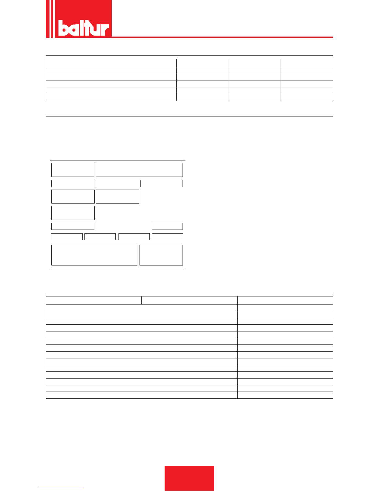
TARGA IDENTIFICAZIONE BRUCIATORE
1 2
3 4 5
6 7
11
14
12
Targa_descr_bru
8
9
10 13
1615
1 Logo aziendale
2 Ragione sociale azienda
3 Codice prodotto
4 Modello bruciatore
5 Matricola
6 Potenza combustibili liquidi
7 Potenza combustibili gassosi
8 Pressione combustibili gassosi
9 Viscosità combustibili liquidi
10 Potenza motore ventilatore
11 Tensione di alimentazione
12 Grado di protezione
13 Paese di costruzione e numeri di certicato di omologazione
14 Anno di costruzione
15 -
16 Codice a barre matricola bruciatore
DATI REGISTRAZIONE PRIMA ACCENSIONE
Modello: Data: ora:
Tipo di gas
Indice di Wobbe inferiore
Potere calorico inferiore
Portata gas
Stm3/h
Portata min gas
Stm³/h
Portata max gas
Stm³/h
Potenza min gas
kW
potenza max gas
kW
Pressione gas di rete
mbar
Pressione gas a valle dello stabilizzatore
mbar
CO
CO2
temperatura fumi
temperatura aria
ITALIANO
7 / 30
0006080763_201611
Page 10
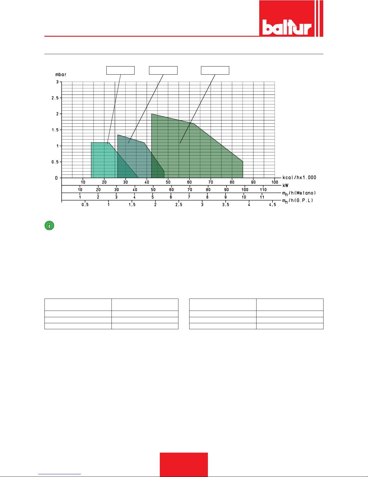
CAMPO DI LAVORO
BTG 3,6 - 3,6P BTG 6 - 6P BTG 11 - 11P
IMPORTANTE
I campi di lavoro sono ottenuti su caldaie di prova rispondenti alla norma EN676 e sono orientativi per gli accoppiamenti bruciatore-caldaia. Per il corretto funzionamento del bruciatore le dimensioni della camera di combustione devono essere rispondenti alla
normativa vigente; in caso contrario vanno consultati i costruttori.
Il bruciatore non deve operare al di fuori del campo di lavoro dato.
¹) EMISSIONI GAS METANO
Classi denite secondo la normativa EN 676.
Classe
Emissioni NOx in mg/kWh gas
metano
1 ≤ 170
2 ≤ 120
3 ≤ 80
²) EMISSIONI GAS PROPANO
Emissioni CO metano / propano ≤ 100 mg/kWh
Classe
Emissioni NOx in mg/kWh gas
propano
1 ≤ 230
2 ≤ 180
3 ≤ 140
ITALIANO
8 / 30
0006080763_201611
Page 11
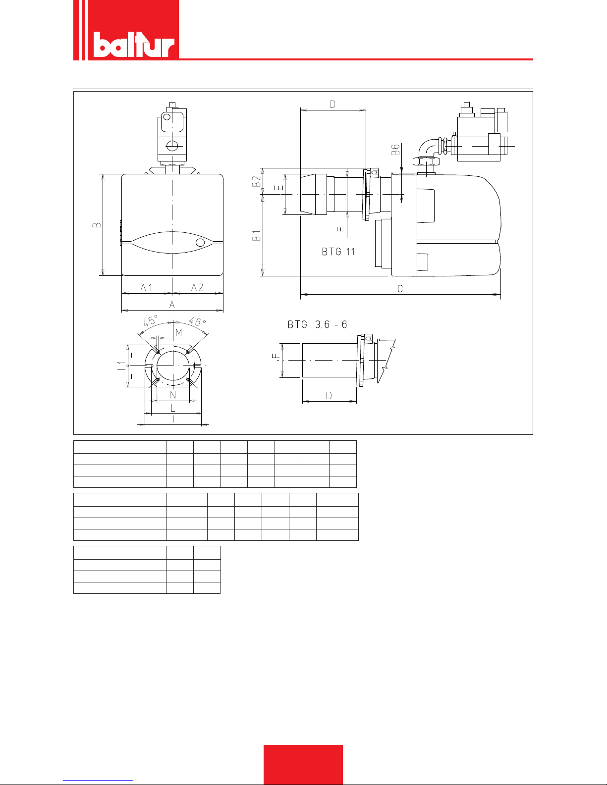
DIMENSIONI DI INGOMBRO
0002470861
Modello A A1 A2 B1 B2 B6 C
BTG 3,6P 246 123 123 219 70 53 410
BTG 6P 246 123 123 219 70 53 410
BTG 11P 246 123 123 219 70 53 475
Modello D E Ø F Ø I I1 LØ
BTG 3,6P 50 ÷ 105 90 90 170 140 130 ÷ 155
BTG 6P 50 ÷ 105 90 90 170 140 130 ÷ 155
BTG 11P 90 ÷ 150 108 90 170 140 130 ÷155
Modello M N Ø
BTG 3,6P M8 95
BTG 6P M8 95
BTG 11P M8 95
ITALIANO
9 / 30
0006080763_201611
Page 12
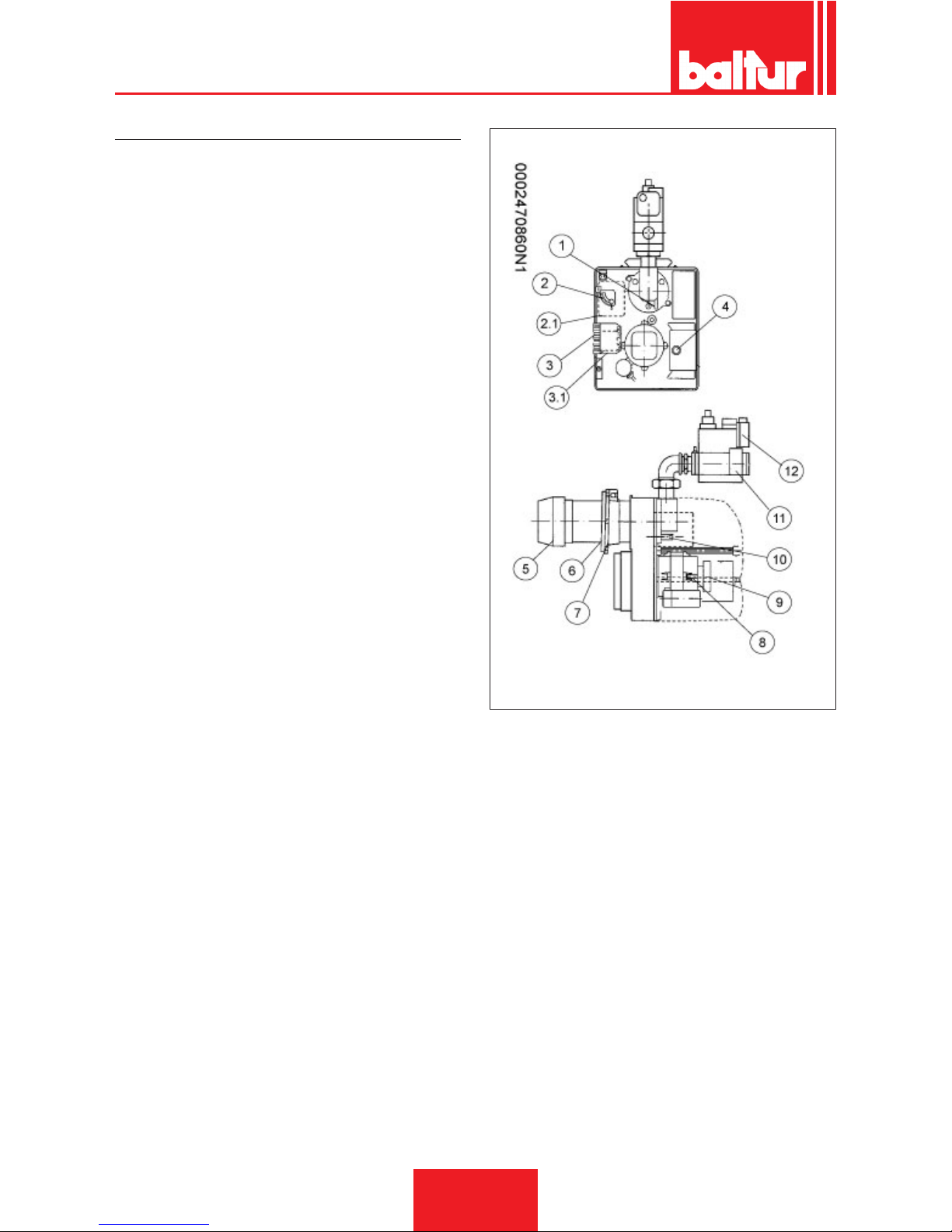
DESCRIZIONE COMPONENTI
1 Riferimento disposizione disco - testa
2 Vite di regolazione apertura serranda aria
3 Connettore 7 poli
4 Connettore 4 poli
5 Apparecchiatura
6 Testa di combustione
7 Guarnizione isolante
8 Flangia attacco bruciatore
9 Motore
10 Pressostato aria
11 Vite regolazione disco testa
12 Elettrovalvola gas
13 Pressostato di minima pressione gas
ITALIANO
10 / 30
0006080763_201611
Page 13
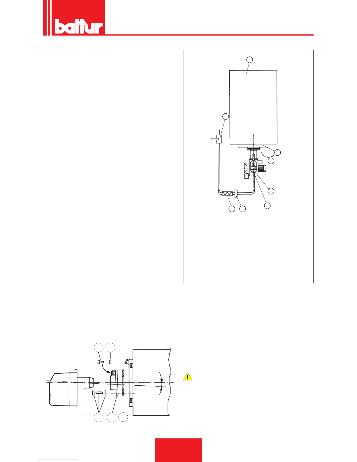
APPLICAZIONE DEL BRUCIATORE ALLA
CALDAIA
La tubazione di adduzione gas deve essere dimensionata in funzione della lunghezza e della erogazione di gas secondo norma
UNI; deve essere perfettamente ermetica ed adeguatamente pro-
vata prima del collaudo del bruciatore.
E’ indispensabile installare, su questa tubazione, in prossimità del
bruciatore un raccordo adatto per consentire un agevole smontaggio del bruciatore e/o l’apertura del portellone della caldaia.
Il bruciatore è dotato di angia di attacco scorrevole sulla testa di
combustione.
Quando si applica il bruciatore alla caldaia occorre posizionare
correttamente detta angia afnchè la testa di combustione penetri nel focolare nella quantità richiesta dal Costruttore della caldaia.
Quando il bruciatore è correttamente applicato alla caldaia si
provvede a collegarlo alla tubazione del gas.
Se la valvola incorpora ltro e stabilizzatore di pressione gas, sulla
tubazione di adduzione del gas, deve essere installato solo il rubinetto di intercettazione e giunto antivibrante.
Solo nel caso in cui la pressione del gas fosse superiore al valore
massimo ammesso dalle norme occorre installare, sulla tubazione
del gas, all’esterno della centrale termica un adatto riduttore di
pressione.
Installare una curva direttamente sulla rampa gas del bruciatore
prima di applicare il raccordo smontabile, così da consentire l’a-
pertura dell’eventuale portellone della caldaia, dopo aver aperto il
raccordo stesso.
1
2
3
4
5
67
8
8871
1 Caldaia
2 Portellone
3 Senso di apertura portellone
4 Bruciatore
5 Valvola gas DUNGS Monoblocco
6 Raccordo
7 Giunto antivibrante
8 Saracinesca
9
7
19
13
0002932940
5
A
• Applicare la guarnizione isolante (13) tra la angia ssaggio bru-
ciatore e la piastra caldaia.
• Fissare la angia (19) alla caldaia attraverso i prigionieri con i
relativi dadi e rondelle (7)
• Inlare il bruciatore nella angia e stringere la vite (5) con il dado
(9).
PERICOLO / ATTENZIONE
Durante il ssaggio del bruciatore sulla angia, posizionare
l'asse della testa di combustione come in gura (angolo A).
ITALIANO
11 / 30
0006080763_201611
Page 14

COLLEGAMENTI ELETTRICI
• Rispettare le normative nazionali ed europee applicabili (es. EN
60335-1/EN 50165) relative alla sicurezza elettrica;
• Le versioni a gas, con elettrodo di rilevazione, sono provviste di
un dispositivo di riconoscimento della polarità.
• Il mancato rispetto della polarità fase-neutro provoca un arresto
di blocco non volatile alla ne del tempo di sicurezza; In caso di
cortocircuito "parziale" o un insufciente isolamento tra linea e
terra, la tensione sull'elettrodo di rivelazione può essere ridotta
no a provocare l'arresto di blocco dell'apparecchio, a causa
dell'impossibilità di rivelare il segnale di amma.
• Prima della messa in funzione controllare bene i cavi.
• Cablaggi errati possono danneggiare l'apparecchio e compromettere la sicurezza dell'impianto;
• Assicurare un ottimo collegamento fra il morsetto di terra
dell'apparecchio, la carcassa metallica del bruciatore e la terra
dell'impianto elettrico;
• Evitare di posare il cavo di rivelazione assieme a cavi di poten-
za o a quelli d'accensione;
• Usare un cavo e un elettrodo di rivelazione resistenti al calore,
ben isolati verso terra e protetti dalla formazione di condensa o
acqua in generale;
• Utilizzare un cavo d'accensione più corto e diritto possibile e
posarlo lontano da altri conduttori per ridurre al minimo l'emis-
sione di radiodisturbi,
• (lunghezza massima inferiore ai 2 m e tensione di isolamento
> 25 kV);
• Questo apparecchio è fornito di fusibili interni, ma deve essere
protetto con un fusibile almeno sulla connessione di linea.
ITALIANO
12 / 30
0006080763_201611
Page 15

DESCRIZIONE DEL FUNZIONAMENTO
Chiudendo l’interruttore generale, se i termostati sono chiusi, la
tensione raggiunge l’apparecchiatura di comando e controllo che,
dopo un breve tempo di attesa, procede all’avviamento del bruciatore secondo il programma previsto.
Viene così inserito il motore del ventilatore che, iniziando a funzio-
nare determina la preventilazione della camera di combustione.
Successivamente si inserisce l’accensione, e dopo tre secondi,
si aprono la valvola di sicurezza e quella di funzionamento (principale).
Compare così la amma che, rilevata dal dispositivo di controllo
della stessa, consente il proseguimento e completamento della
fase di accensione.
Nel caso in cui la amma non comparisse, l’apparecchiatura entra
in “blocco di sicurezza” in 3 secondi dall’apertura delle valvole del
gas (funzionamento e sicurezza).
In caso di “blocco di sicurezza” le valvole del gas vengono immediatamente richiuse.
Per sbloccare l’apparecchiatura dalla posizione di sicurezza, occorre premere il pulsante rosso sull’apparecchiatura.
ACCENSIONE E REGOLAZIONE
Prima di qualsiasi operazione d’accensione vericare che la camera di combustione sia libera da gas.
Con bruciatore trifase, vericare che il senso di rotazione del mo-
tore sia corretto.
• Vericare che ci sia acqua in caldaia e che le saracinesche
dell’impianto siano aperte.
Effettuare lo spurgo dell’aria contenuta nella tubazione del gas, se
non è già stato fatto all’atto del collegamento del bruciatore alla
tubazione del gas con le cautele del caso e con porte e nestre
aperte.
Attendere no a quando si avverte l'odore caratteristico del gas e
quindi chiudere il rubinetto.
Occorre aprire il raccordo sulla tubazione in prossimità del bruciatore e, successivamente, aprire un poco il o i rubinetti di intercet-
tazione del gas.
• Vericare che lo scarico dei prodotti della combustione attraverso le serrande caldaia e serrande camino, possa avvenire
liberamente.
• Aprire, della quantità che si presume necessaria, il regolatore
dell’aria di combustione e aprire di circa un terzo il passaggio
dell’aria tra testa e disco.
• Agire sui regolatori incorporati nella valvola di sicurezza e di
funzionamento in modo da consentire l'erogazione di gas che si
presume necessaria.
• Disinserire il termostato del secondo stadio per evitare l’inserzione e dare corrente al bruciatore inserendo l’interruttore generale.
• Il bruciatore viene così inserito ed effettua la fase di preventilazione.
• Se il pressostato di controllo della pressione dell’aria rileva una
pressione superiore al valore a cui è regolato, si inserisce il
trasformatore d’accensione e, successivamente si inseriscono
anche le valvole gas (di sicurezza e di prima amma).
• Le valvole si aprono completamente e l’erogazione di gas è li-
mitata dalla posizione in cui è stato regolato, manualmente, il
regolatore di portata incorporato nella valvola di funzionamento
(principale).
• Alla prima accensione possono vericarsi “bloccaggi” successivi dovuti a:
• La tubazione del gas non è stata sfogata dall’aria in modo suf-
ciente e quindi la quantità di gas è insufciente per consentire
una amma stabile.
• Il “bloccaggio” con presenza di amma, può essere causato da
instabilità della stessa nella zona di ionizzazione, per un rappor-
to aria gas non corretto.
• Si rimedia variando la quantità di aria e/o di gas erogati in modo
da trovare il corretto rapporto.
• Lo stesso inconveniente puo’ essere causato da una non cor-
retta distribuzione aria/gas nella testa di combustione.
• Si rimedia agendo sul dispositivo di regolazione della testa di
combustione chiudendo o aprendo maggiormente il passaggio
dell’aria tra testa e diffusore gas, attraverso il sistema regola-
zione disco amma.
• Può capitare che la corrente di ionizzazione sia contrastata dalla corrente di scarica del trasformatore di accensione (le due
correnti hanno un percorso in comune sulla “massa” del bruciatore) pertanto il bruciatore si porta in blocco per insufciente
ionizzazione.
• Si rimedia invertendo l’alimentazione (lato 230V) del trasforma-
tore di accensione (si scambiano di posto i due li che portano
la tensione al trasformatore).
• Detto inconveniente può anche essere causato da un insuf-
ciente “messa a terra” della carcassa del bruciatore.
• Precisiamo che il valore minimo della corrente di ionizzazione
per assicurare il funzionamento dell’apparecchiatura è esposto
sullo schema elettrico.
• Con bruciatore acceso adeguare l’erogazione al valore desi-
derato per la “prima amma” effettuando la lettura al contatore.
• La portata può essere modicata agendo sull’apposito regolato-
re incorporato alla valvola, come sopra esposto.
• Controllare, mediante gli appositi strumenti, che la combustione
avvenga correttamente (CO2 max.= circa 10% per metano - CO
max. = 0,1 %).
• Dopo aver effettuato la regolazione occorre spegnere e riaccendere alcune volte il bruciatore per vericare che l’accensione avvenga regolarmente.
ITALIANO
13 / 30
0006080763_201611
Page 16
• Con bruciatore disinserito dall’interruttore generale, effettuare il
collegamento del termostato della seconda amma.
• Aprire anche il regolatore della portata del gas incorporato nella
seconda valvola per consentire un’erogazione che si presume
necessaria per la amma principale.
• Chiudere ora l’interruttore generale per accendere il bruciatore.
• Quando il bruciatore è acceso con la seconda amma, occorre
vericare. come esposto precedentemente, l’erogazione di gas
e la combustione con gli appositi strumenti.
• In funzione dei rilievi effettuati si procede variando, se necessa-
rio, l’erogazione del gas e della relativa artia di combustione per
adeguare l’erogazione al valore desiderato per il caso specico
(potenzialità caldaia).
• Vericare con gli appositi strumenti i parametri di combustione
(CO2 MAX= 10% O2 MIN= 3% CO MAX=0,1%)
• Controllare l’efcienza dei dispositivi di sicurezza, blocco (stac-
cando il cavo dell’elettrodo di ionizzazione) pressostato aria,
pressostato gas, termostati.
IMPORTANTE
Il circuito di collegamento del pressostato prevede l’ auto-
controllo, quindi, è necessario che il contatto previsto per
essere chiuso a riposo (ventola ferma e di conseguenza
assenza di pressione aria nel bruciatore), realizzi effettivamente questa condizione, in caso contrario l’ apparecchiatura di comando e controllo non viene inserita (il bruciatore
resta fermo).
• Precisiamo che se non si chiude il contatto previsto per essere
chiuso in lavoro, l’ apparecchiatura esegue il suo ciclo ma non
si inserisce il trasformatore d’ accensione e non si aprono le val-
vole del gas, di conseguenza il bruciatore si arresta in “blocco”.
• Per accertare il corretto funzionamento del pressostato aria
occorre, con bruciatore acceso,aumentarne il valore di regolazione no a vericarne l’ intervento a cui deve conseguire l’
immediato arresto in “blocco” del bruciatore.
• Sbloccare il bruciatore, premendo l’apposito pulsante e riportare la regolazione del pressostato ad un valore sufciente per
rilevare la pressione di aria esistente durante la fase di preventilazione.
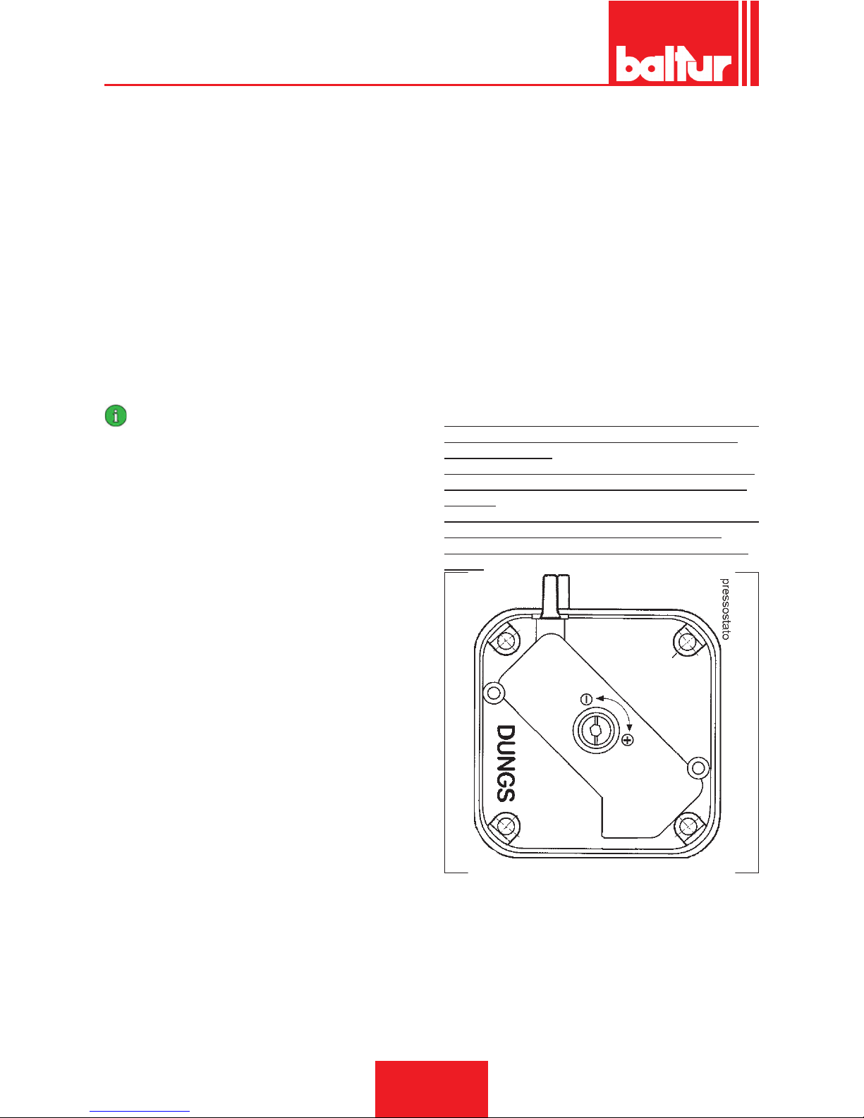
PRESSOSTATO ARIA
Il pressostato aria ha lo scopo di mettere in sicurezza (blocco)
l’apparecchiatura se la pressione dell’aria non è quella prevista.
Il pressostato deve quindi essere regolato per intervenire chiudendo il contatto NO (normalmente aperto) quando la pressione
dell’aria nel bruciatore raggiunge il valore sufciente.
Qualora il pressostato aria non rilevi una pressione superiore a
quella di taratura, l'apparecchiatura esegue il suo ciclo ma non si
inserisce il trasformatore d'accensione e non si aprono le valvole
del gas e di conseguenza il bruciatore si arresta in "blocco"
Per vericare il corretto funzionamento del pressostato aria, occorre, con bruciatore al minimo dell’erogazione, aumentare il valore di regolazione no a vericare l’intervento a cui deve conseguire l’immediato arresto in “blocco” del bruciatore.
Sbloccare il bruciatore premendo l’apposito pulsante e riportare la
regolazione del pressostato ad un valore sufciente per rilevare
una pressione di aria esistente durante la fase di preventilazione.
Il punto di prelievo della pressione aria si trova a monte delle serrande aria.
Eseguire la regolazione del pressostato aria dopo aver effettuato
tutte le altre regolazioni del bruciatore con il pressostato aria
regolato a inizio scala.
Con il bruciatore funzionante a bassa portata (1° amma), agire
sulla vite centrale lentamente in senso orario no al blocco del
bruciatore.
Ruotare quindi in senso antiorario la vite di circa 1/2 giro e ripetere l’avviamento del bruciatore per vericarne la regolarità.
Se il bruciatore si blocca nuovamente, ruotare ancora la vite di
1/2 giro.
ITALIANO
14 / 30
0006080763_201611
Page 17
REGOLAZIONE ARIA SULLA TESTA DI COMBUSTIONE
La testa di combustione è dotata di un dispositivo di regolazione
che permette di aprire o chiudere il passaggio dell’aria tra il disco
e la testa.
Chiudendo il passaggio aria si riesce così ad ottenere un’elevata
pressione a monte del disco anche con basse portate.
L’elevata velocità e turbolenza dell’aria consente una migliore
miscelazione con il combustibile e quindi, un’ottima stabilità di
amma.
Può essere indispensabile avere un’elevata pressione d’aria a
monte del disco per evitare pulsazioni di amma, condizione indispensabile quando il bruciatore lavora su focolare pressurizzato
e/o ad alto carico termico.
Pertanto, il dispositivo di regolazione aria sulla testa di combustione, deve essere portato in una posizione tale da ottenere sempre
dietro al disco, un valore decisamente elevato di pressione.
Per ottenere questo è necessario ssare il dispositivo in una posizione intermedia sulla chiusura aria sulla testa, ed agire sul di-
spositivo serranda aria aumentando il usso all’aspirazione della
ventola; ovviamente questa condizione si deve vericare quando
il bruciatore lavora alla massima potenza richiesta dall'impianto.
Correggere la posizione del dispositivo chiusura aria della testa
di combustione, spostandolo in avanti o indietro, in modo da avere un usso d’aria adeguato all’erogazione, con serranda aria in
aspirazione sensibilmente aperta.
Riducendo il passaggio dell’aria sulla testa di combustione, occor-
re evitarne la chiusura completa.
Controllare che l'accensione avvenga regolarmente, se l'apertura
della testa è eccessiva, si potrebbe vericare forte turbolenza d'aria e quindi difcoltà d'accensione.
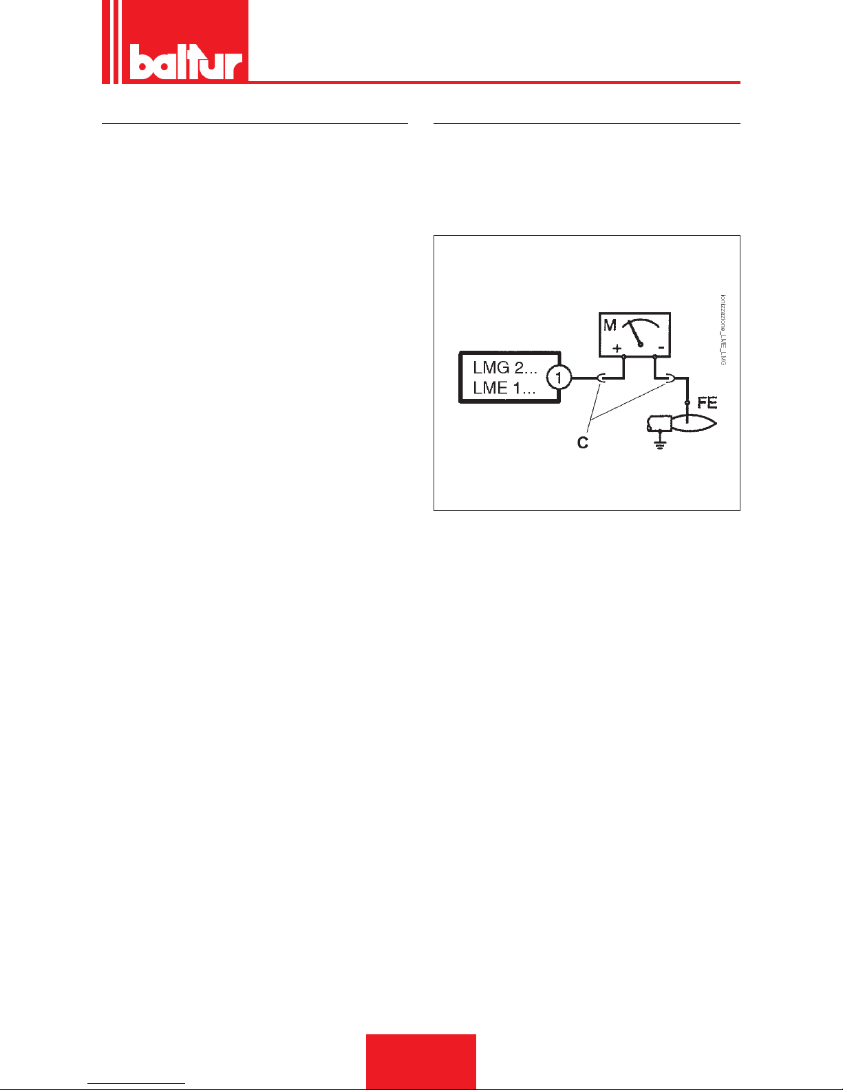
CORRENTE IONIZZAZIONE
La corrente minima di ionizzazione per far funzionare l’apparec-
chiatura è di 3 μA.La amma del bruciatore genera una corrente
nettamente superiore, tale da non richiedere normalmente alcun
controllo da parte dell’apparecchiatura.Qualora si voglia misurare
la corrente di ionizzazione bisogna collegare un microamperometro in serie al cavetto dell’elettrodo di ionizzazione aprendo il con-
nettore “C”, vedi schema elettrico.
ITALIANO
15 / 30
0006080763_201611
Page 18
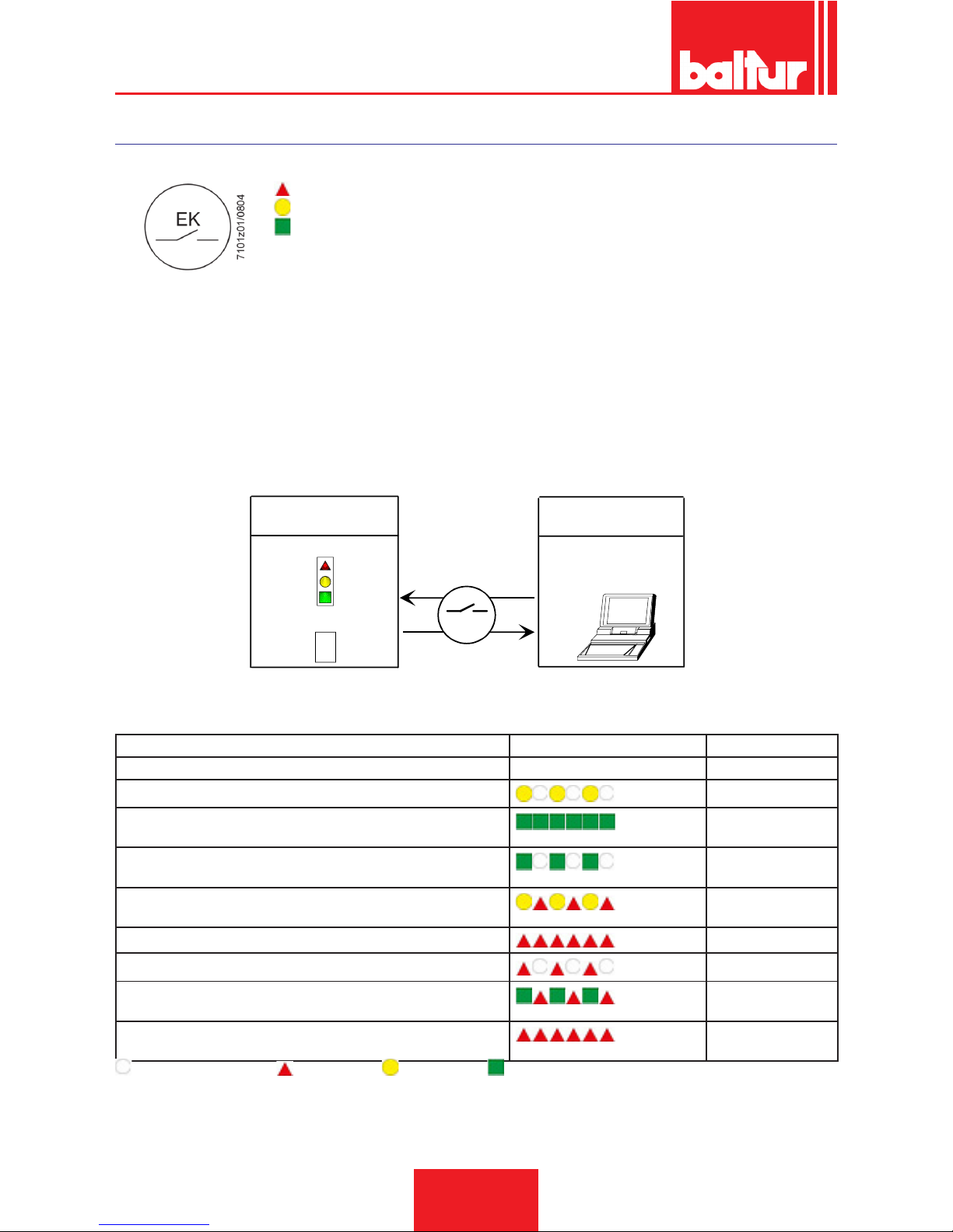
APPARECCHIATURA DI COMANDO E CONTROLLO LME...
FUNZIONAMENTO.
ROSSO
GIALLO
VERDE
Il pulsante di sblocco «EK...» è l’elemento principale per poter accedere a
tutte le funzioni di diagnostica (attivazione e disattivazione), oltre a sbloc-
care il dispositivo di comando e controllo.
Sia «LED» che «EK...» sono posizionati sotto il pulsante trasparente, premendolo si procede allo sblocco del dispositivo di comando e
controllo.
Possibilità di due funzioni di diagnostica:
1. Indicazione visiva direttamente sul pulsante di sblocco, funzionamento e diagnosi dello stato del dispositivo.
2. Diagnostica con interfaccia, in questo caso è necessario il cavo di collegamento OCI400 che può essere collegato ad un PC con
software ACS400, o ad analizzatori gas di differenti costruttori.
INDICAZIONE VISIVA.
Durante il funzionamento, sul pulsante di sblocco è indicata la fase in cui il dispositivo di comando e controllo si trova, nella tabella sono
riepilogate le sequenze dei colori ed il loro signicato. Per attivare la funzione di diagnosi premere per almeno 3 secondi il pulsante di
sblocco, un lampeggio veloce di colore rosso indicherà che la funzione è attiva; analogamente per disattivare la funzione basterà premere
per almeno 3 secondi il pulsante di sblocco, (la commutazione verrà indicata con luce gialla lampeggiante).
EK
xxxxxxxx
xxxxxxxx
xxxxxxxx
xxxxxxxx
xxxxxxxx
xxxxxxxx
> 3 s
7101z03e0305
Posizione di funzionamento
interfaccia PC / analizzatore
diagnostica
Tabella codici colore
Diagnostica
Posizione di funzionamento
INDICAZIONI DELLO STATO DEL DISPOSITIVO DI COMANDO E CONTROLLO.
Condizione Sequenza colori Colori
Condizioni di attesa TW, altri stati intermedi . . . . . . . . Nessuna luce
Fase di accensione
Giallo intermittente
Funzionamento corretto, intensità di corrente rilevatore amma superiore al minimo ammesso
Verde
Funzionamento non corretto, intesità di corrente rilevatore amma
inferiori al minimo ammesso
Verde intermittente
Diminuzione tensione di alimentazione
Giallo e Rosso
alternati
Condizione di blocco bruciatore
Rosso
Segnalazione guasto (vedere legenda colori)
Rosso intermittente
Luce parassita durante l’accensione del bruciatore
Verde Rosso alternati
Lampeggìo veloce per diagnostica
Rosso lampeggiante
rapido
NESSUNA LUCE. ROSSO. GIALLO. VERDE.
ITALIANO
16 / 30
0006080763_201611
Page 19
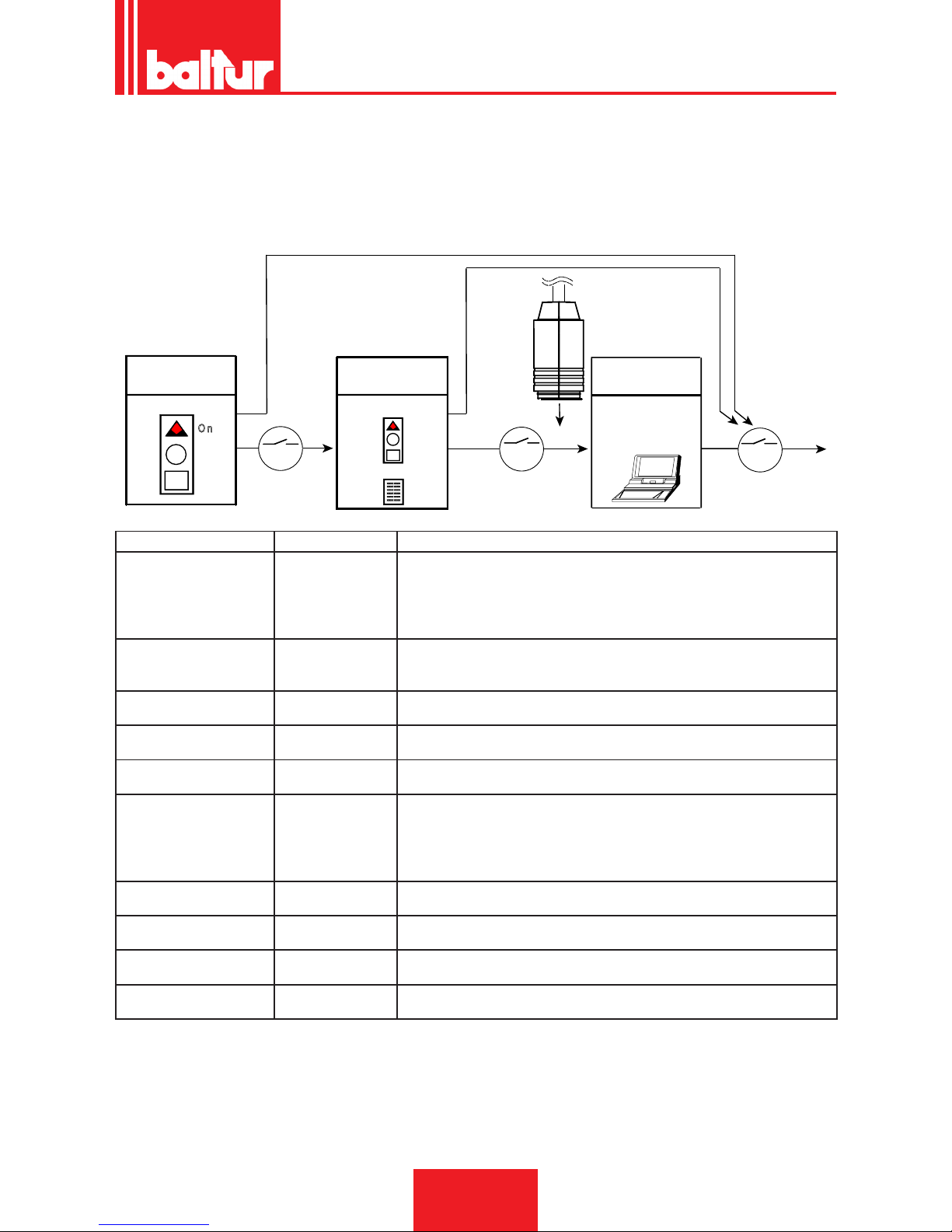
DIAGNOSI DELLE CAUSE DI MALFUNZIONAMENTO E BLOCCO.
In caso di blocco bruciatore nel pulsante di sblocco sarà ssa la luce rossa.
Premendo per più di 3 sec. la fase di diagnosi verrà attivata (luce rossa con lampeggio rapido), nella tabella sottostante viene riportato il
signicato della causa di blocco o malfunzionamento in funzione del numero di lampeggi (sempre colore rosso).
Premendo il pulsante di sblocco per almeno 3 sec. si interromperà la funzione di diagnosi.
Lo schema sotto riportato indica le operazioni da eseguire per attivare le funzioni di diagnostica anche con interfaccia di comunicazione
attraverso il cavo di collegamento "OCI400".
E K
> 3 s
xxxxxxxx
xxxxxxxx
xxxxxxxx
xxxxxxxx
xxxxxxxx
xxxxxxxx
E K
OCI400
E K
< 3 s
7101z04e0305
R e s e t
O n
> 3 s
Posizione di
funzionamento
Posizione di
funzionamento
Indicazione visiva
Tabella codici colore
Posizione di
funzionamento
Interfaccia PC /
analizzatore
diagnostica
Indicazione ottica "AL" al morsetto 10 Possibili cause
2 lampeggi
●●
On Assenza del segnale di amma alla ne del tempo di sicurezza <TSA>
- Malfunzionamento valvole combustibile
- Malfunzionamento rilevatore amma
- Difettosità nella taratura del bruciatore, assenza di combustibile
- Mancata accensione difettosità trasformatore di accensione
3 lampeggi
●●●
On - Malfunzionalità pressostato aria LP
- Mancanza segnale pressostato dopo T10
- Contatto del pressostato LP incollato in posizione di riposo
4 lampeggi
●●●●
On Luce estranea durante la fase di accensione
5 lampeggi
●●●●●
On - Assenza segnale pressostato aria LP
- Contatto del pressostato LP incollato in posizione di lavoro
6 lampeggi
●●●●●●
On Non utilizzata
7 lampeggi
●●●●●●●
On Assenza del segnale di amma durante funzionamento normale, ripetizione
accensione (limitazione nel numero delle ripetizioni dell’accensione)
- Anomalia delle valvole combustibile
- Anomalie del rilevatore amma
- Difettosità nella taratura del bruciatore
8 lampeggi
●●●●●●●●
On Non utilizzata
9 lampeggi
●●●●●●●●●
On Non utilizzata
10 lampeggi
●●●●●●●●●●
On Problemi di cablaggio elettrico o danneggiamenti interni al dispositivo
14 lampeggi
●●●●●●●●●●●●●●
On CPI contatto non chiuso
• In condizioni di diagnosi di anomalia il dispositivo rimane disattivato.
• - Il bruciatore è spento.
• - La segnalazione di allarme «AL» è sul morsetto 10 che è sotto tensione.
• Per riattivare il dispositivo e iniziare un nuovo ciclo procedere premendo per 1 sec. (< 3 sec) il pulsante di sblocco.
ITALIANO
17 / 30
0006080763_201611
Page 20
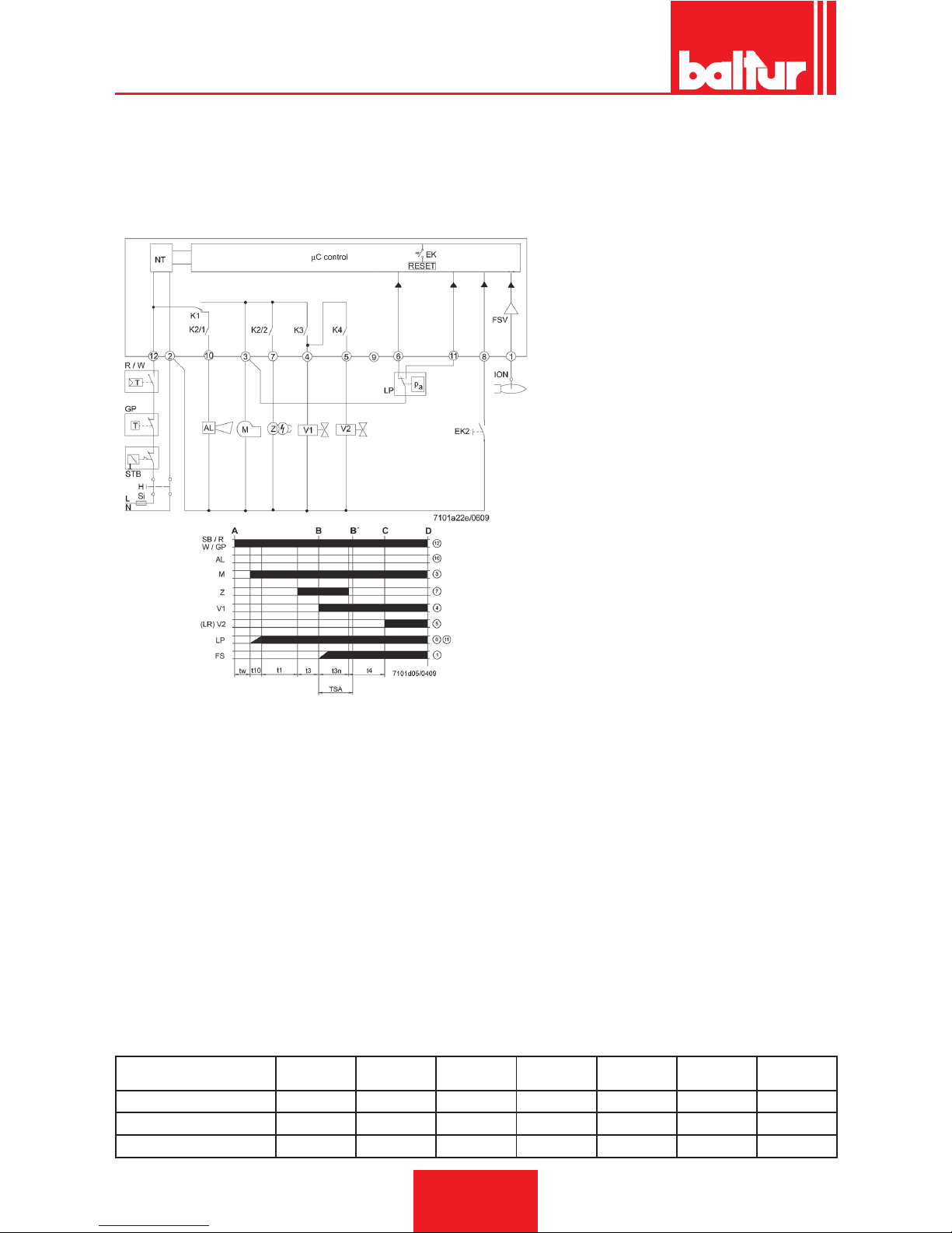
SCHEMA DEI COLLEGAMENTI E CONTROLLO DELLA SEQUENZA DI
LAVORO DELL'APPARECCHIATURA LME 21...(QUANDO SI UTILIZZA IL
COLLEGAMENTO CON DEGLI ATTUATORI, È NECESSARIO OSSERVARE I REQUISITI EN 676)
I 1° Camma attuatore
t1 Tempo di preventilazione
t1´ Tempo di ventilazione
t3 Tempo pre-accensione
t3n Tempo di post-accensione
t4 Intervallo tra l’accensione «Off» ed l’apertura di «BV2»
t10 Tempo disponibile per la rilevazione della pressione aria del pressostato
t11 Tempo di apertura programmato per l’attuatore «SA»
t12 Tempo di chiusura programmato per l’attuatore «SA»
t22 2° tempo di sicurezza
TSA Tempo di sicurezza per l’accensione
tw Tempo di attesa
AGK25... Resistenza PTC
AL Messaggio di errore (allarme)
BCI Interfaccia di Comunicazione del Bruciatore
BV... Valvola del Combustibile
CPI Indicatore di Posizione Chiusa
Dbr.. Ponticello cablaggio
EK.. Pulsante di reset del blocco remoto (interno)
EK2 Pulsante di reset del blocco remoto
ION Sonda di Ionizzazione
FS Segnale di Fiamma
FSV Amplicatore del segale di amma
GP Pressostato gas
H Interruttore principale
HS Contatto ausiliario, relè
ION Sonda di Ionizzazione
K1...4 Relè Interni
KL Fiamma bassa
LK Serranda dell’Aria
LKP Posizione della serranda dell’aria
LP Pressostato aria
LR Modulazione
M Motore ventola
MS Motore sincrono
NL Carico nominale
NT Alimentatore elettrico
QRA... Rivelatore di Fiamma
QRC… Rivelatore di amma blu bl br marrone sw nero
R Termostato / pressostato di controllo
RV Dispositivo di regolazione del gas
SA Attuatore SQN...
SB Termostato di limiti di sicurezza
STB Termostato di limiti di sicurezza
Si Fusibile esterno
t Tempo
W Termostato di Limiti / Pressostato
Z Trasformatore dell’accensione
ZV Valvola a gas pilota
A Comando di Avvio (accensione da «R»)
B-B´ Intervallo per la formazione della amma
C Bruciatore arrivato in posizione di funzionamento
C-D Funzionamento del bruciatore (generazione di calore)
D Spegnimento controllato da «R»
Il bruciatore viene spento immediatamente
Il controllo del bruciatore sarà immediatamente pronto per un
nuovo avvio
Apparecchiatura o pro-
grammatore
TSA t1 t3 t3n t4 t11 t12
s s s s s s s
LME 21.350 C2 5 30 2 4,5 10 - -
LME 21.430 C2 3 40 2 2,5 8 - -
ITALIANO
18 / 30
0006080763_201611
Page 21
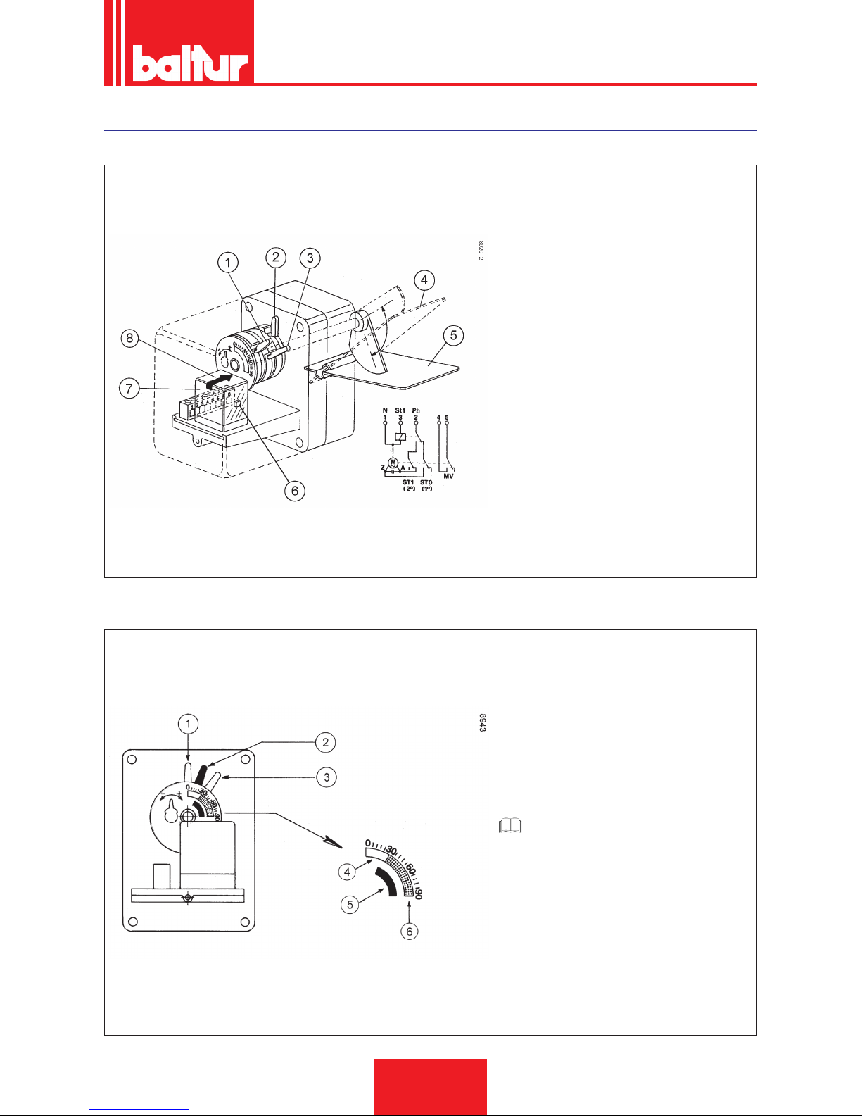
SERVOMOTORE COMANDO SERRANDA ARIA CONNECTRON “LKS 120-02 (B5-5-51)
A BRUCIATORE FERMO, SERRANDA ARIA CHIUSA.
1) Camma inserzione valvola 2° amma (colore nero)
deve essere in posizione intermedia tra le camme
che regolano l’aria della 1° e 2° amma
2) Camma regolazione aria 1° amma (colore az-
zurro)
3) Camma regolazione aria 2° amma (colore rosso)
4) Serranda aria in posizione aperta
5) Serranda aria in posizione chiusa
6) Pulsante inserzione manuale 2° amma
7) Relè inversione del senso di rotazione
8) Riferimento indice servocomando.
1 Neutro
2 Fase
3 Termostato 2° amma
4/5 Micro interruttore per valvola 2° amma
REGOLAZIONE, PER LA PRIMA ACCENSIONE DEL SERVOMOTORE.
A titolo indicativo, per la prima accensione, regolare
le cammes nel seguente modo:
1) Camma inserzione valvola 2° amma (colore nero)
40°
2) Camma regolazione aria 1° amma (colore azzurro) 25°
3) Camma regolazione aria 2° amma (colore rosso)
50°
4) Azzurro
5) Nero
6) Rosso
CAUTELA / AVVERTENZE
La posizione delle cammes dovrà essere ade-
guata all’erogazione effettiva di combustibile,
vericando la combustione con gli appositi
strumenti.
La portata d’aria in posizione di 1° amma
deve corrispondere almeno al 50% della portata d’aria totale.
ITALIANO
19 / 30
0006080763_201611
Page 22
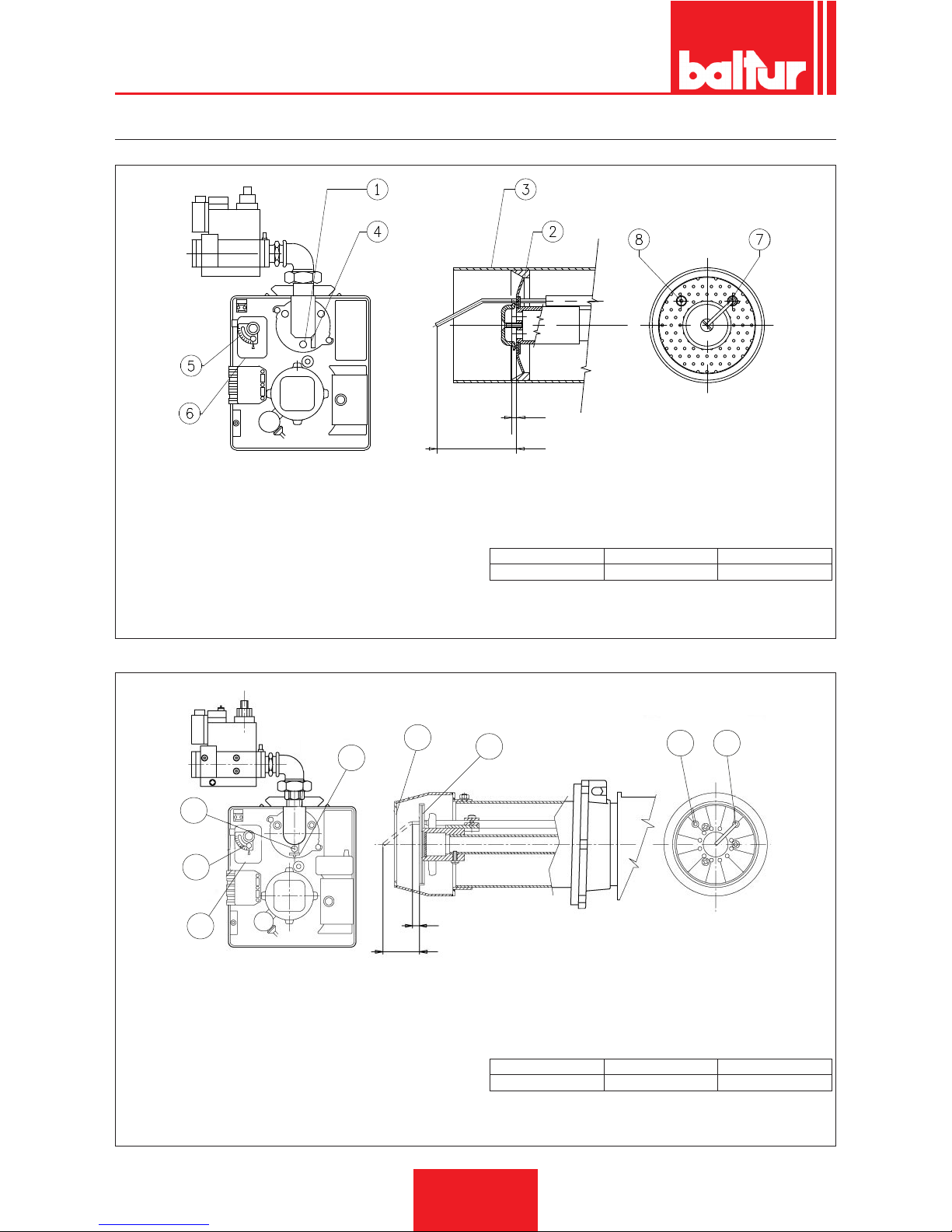
SCHEMA DI REGOLAZIONE TESTA DI COMBUSTIONE E DISTANZA DISCO ELETTRODI
BTG 3,6 - 6P
A
B
0002933473
1 - Vite regolazione disco-testa (avvitare per aprire il passaggio
aria tra disco e testa, svitare per chiudere)
2 - Disco: Attenzione: evitare la chiusura completa
3 - Testa di combustione
4 - Riferimento posizione disco-testa
5 - Sistema regolazione aria manuale
6 - Servomotore regolazione aria solo per BTG 3,6P- 6P
7 - Elettrodo ionizzatore
8 - Elettrodo d’accensione
A - Sporgenza elettrodo d’accensione
B - Sporgenza elettrodo ionizzatore
A B
BTG 3,6P - 6P 1 0+1 56 ±1
BTG 11P
1
5
6
4
3
2
7 8
A
B
0002936370
1 - Vite regolazione disco-testa (avvitare per aprire il passaggio
aria tra disco e testa, svitare per chiudere)
2 - Disco: Attenzione: evitare la chiusura completa
3 - Testa di combustione
4 - Riferimento posizione disco-testa
5 - Sistema regolazione aria manuale
6 - Servomotore regolazione aria solo per BTG 11
7 - Elettrodo d’accensione
8 - Elettrodo ionizzatore
A - Sporgenza elettrodo d’accensione
B - Sporgenza elettrodo ionizzatore
A B
BTG 11P 7 ±1 52 ±1
ITALIANO
20 / 30
0006080763_201611
Page 23
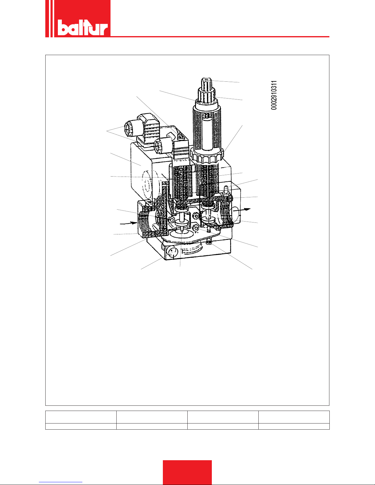
VALVOLA GAS COMBINATA (MONOBLOCCO) DUNGS MOD. MB-DLE ...
1
2
2
A
3
4
5
16
6
17
12
13
5 (Pa)
7 (Pa)
14
15
8
9
10
11
B
A Collegamenti elettrici
B Senso del usso
1 Vite bloccaggio regolatori di 1° e 2° amma
2 Coperchio vite regolazione stabilizzatore pressione
3 Pressostato gas (minima)
4 Valvola di sicurezza
5 Presa di pressione ingresso gas
6 Filtro
7 Presa di pressione dopo lo stabilizzatore di pressione (Pa)
8 Valvola principale (l° e 2° amma)
9 Anello regolazione erogazione 1° amma
10 Manopola regolazione erogazione 2° amma
11 Coperchio di protezione (con uso manopola) del dispositivo di
regolazione dello scatto rapido iniziale.
12 Stabilizzatore di pressione
13 Tappo
14 Flangia uscita
15 Presa di pressione in uscita valvola
16 Flangia entrata
17 Sato dello stabilizzatore di pressione
Valvola modello Pressione max ingresso (PE) mbar
Pressione regolabile in uscita
stabilizzatore (Pa) mbar
Tipo di gas utilizzato
MB … … B01 S 20 360 da 4 a 20 Gas naturale / G.P.L.
ITALIANO
21 / 30
0006080763_201611
Page 24
Il gruppo valvole gas DUNGS MB-DLE... è costituito da:
• Pressostato di minima pressione gas (3)
• Filtro gas (6)
• Regolatore (stabilizzatore) di pressione (2)
• Valvola di sicurezza (incorporata nel regolatore di pressione) ad
apertura e chiusura rapida (4)
• Valvola principale a due posizioni (1° amma e 2° amma) ad
apertura lenta con scatto rapido iniziale regolabile e chiusura
rapida (8)
• Per procedere alla regolazione esponiamo le seguenti precisazioni.
• 1) Filtro di ingresso (6) accessibile per la pulizia asportando una
delle due piastrine laterali di chiusura
• Stabilizzazione di pressione regolabile (vedi tabella) tramite
la vite accessibile facendo scorrere lateralmente il coperchio
(2).La corsa completa dal minimo al massimo e viceversa richie-
de circa 60 giri completi, non forzare contro i ne corsa.Prima di
accendere il bruciatore dare almeno 15 giri verso il segno +.Attorno all’orizio di accesso sono riportate le frecce con i simboli
che indicano il senso di rotazione per l’aumento della pressione
(rotazione in senso orario) e quello per la diminuzione (rotazione in senso antiorario).Detto stabilizzatore realizza la chiusura
ermetica tra “monte” e “valle” quando manca il usso.Non sono
previste molle diverse per ottenere valori di pressione diversi
da quelli sopra esposti.Per la regolazione dello stabilizzatore di
pressione collegare il manometro ad acqua al portagomma in-
stallato sulla valvola, alla presa Pa (7) corrispondente all’uscita
dello stabilizzatore.
• Valvola di sicurezza di apertura rapida e chiusura rapida (4) non
è provvista di regolazione.
• Valvola principale (8).
• Regolazione scatto rapido iniziale che agisce sia sulla prima
che sulla seconda posizione di apertura della valvola.La regolazione dello scatto rapido e il freno idraulico agiscono sulle posizioni l° e 2° della valvola proporzionalmente alle regolazioni
di portata.Per effettuare la regolazione, svitare il coperchio di
protezione (11) e usare la sua parte posteriore come attrezzo
per far ruotare il perno.
Rotazione oraria=scatto rapido minoreRotazione antioraria=scatto rapido maggiore
REGOLAZIONE PRIMA POSIZIONE (1° FIAMMA)
• Allentare la vite con testa cilindrica sporgente (1).
• Ruotare di almeno 1 giro nel senso indicato dalla freccia con il
segno + (rotazione antioraria) la manopola (10) di regolazione
della portata della seconda amma.
CAUTELA / AVVERTENZE
Se questa manopola di regolazione della 2° amma non
viene ruotata di almeno un giro verso il + la valvola non si
apre per la prima posizione.
• Ruotare l’anello (9) di regolazione della l° posizione, nel senso
indicato dalla freccia con il segno + (rotazione antioraria).
• Indicativamente poco più di due giri rispetto al ne corsa.
• Successivamente, con la sola prima amma accesa, ruotare
adeguatamente l’anello (9) per ottenere l’erogazione di gas de-
siderata, per la prima amma.
• Precisiamo che la corsa completa, del regolatore di portata, da
- a + e viceversa è di circa tre giri e mezzo.
• La rotazione oraria del regolatore determina una riduzione
dell’erogazione, una rotazione in senso antiorario un aumento
della stessa.
REGOLAZIONE SECONDA POSIZIONE (2A FIAMMA)
• Allentare la vite con testa cilindrica sporgente (1).
• Ruotare la manopola (10) nel senso indicato dalla freccia con
il segno + (rotazione antioraria), della quantità che si presume
necessaria per ottenere l’erogazione di gas desiderata per la
seconda amma.
• Precisiamo che la corsa completa del regolatore da + a - e vice-
versa, è di circa CINQUE giri.
• La rotazione oraria del regolatore determina una riduzione
dell’erogazione e una rotazione in senso antiorario, un aumento della stessa.
• Dopo aver effettuato le regolazioni di erogazione gas, per la
prima e seconda amma ricordarsi di stringere la vite (1) per
evitare spostamenti indesiderati dalle posizioni volute.
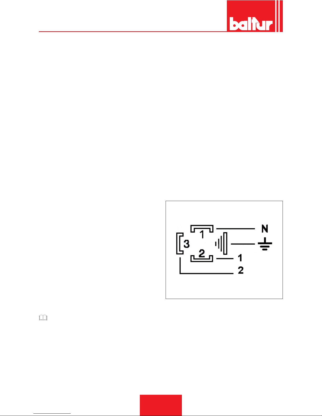
PARTICOLARE MORSETTIERA VALVOLA MB-ZRDLE
N = neutro
1 = 1° posizione
2 = 2° posizione
ITALIANO
22 / 30
0006080763_201611
Page 25

MANUTENZIONE
Effettuare almeno una volta all’anno e comunque in conformità
alle norme vigenti, l’analisi dei gas di scarico della combustione
vericando la correttezza dei valori di emissioni.
Al termine della stagione di riscaldamento, eseguire le seguenti
operazioni:
• Pulire le serrande aria, il pressostato aria con presa di pressio-
ne ed il relativo tubo se presenti.
• Vericare lo stato degli elettrodi. Se necessario sostituirli.
• Pulire la fotocellula. Se necessario sostituirla.
• Far pulire la caldaia ed il camino da personale specializzato in
fumisteria, una caldaia pulita ha maggior rendimento, durata e
silenziosità.
• Controllare che il ltro del combustibile sia pulito. Se necessario
sostituirlo.
• Vericare che tutti i componenti della testa di combustione si-
ano in buono stato, non deformati e privi di impurità o depositi
derivanti dall'ambiente di installazione e/o da una cattiva combustione.
• Effettuare l’analisi dei gas di scarico della combustione vericando la correttezza dei valori di emissioni.
ITALIANO
23 / 30
0006080763_201611
Page 26
TEMPI DI MANUTENZIONE
TESTA DI COMBUSTIONE GAS
ELETTRODI
CONTROLLO VISIVO, INTEGRITA CERAMICHE. SMERIGLIATURA ESTREMITA,
VERIFICARE DISTANZA, VERIFICARE CONNESSIONE ELETTRICA.
ANNUO
DISCO FIAMMA CONTROLLO VISIVO INTEGRITA EVENTUALI DEFORMAZIONI, PULIZIA, ANNUO
SONDA DI IONIZZAZIONE
CONTROLLO VISIVO, INTEGRITA CERAMICHE. SMERIGLIATURA ESTREMITA,
VERIFICARE DISTANZA, VERIFICARE CONNESSIONE ELETTRICA.
ANNUO
COMPONENTI TESTA COMBUSTIONE CONTROLLO VISIVO INTEGRITA EVENTUALI DEFORMAZIONI, PULIZIA, ANNUO
GUARNIZIONE ISOLANTE CONTROLLO VISIVO TENUTA ED EVENTUALE SOSTITUZIONE ANNUO
GUARNIZIONE RACCORDO MANDATA
GAS
CONTROLLO VISIVO TENUTA ED EVENTUALE SOSTITUZIONE ANNUO
LINEA ARIA GAS
GRIGLIA/SERRANDE ARIA PULIZIA ANNO
CUSCINETTI SERRANDA ARIA INGRASSAGGIO, (N.B. mettere solo su bruciatori con cuscinetti da ingrassare) 6 MESI
PRESSOSTATO ARIA PULIZIA ANNO
PRESA E CONDOTTI PRESSIONE ARIA PULIZIA ANNO
COMPONENTI DI SICUREZZA GAS
PRESSOSTATO GAS VERIFICA FUNZIONALE ANNO
COMPONENTI VARI GAS
MOTORI ELETTRICI (CUSCINETTI/VEN-
TOLA RAFFREDDAMENTO)
PULIZIA, (vedere se esistono indicazioni del fornitore) ANNO
LEVE/TIRANTI/SNODI SFERICI (GIOCHI/
LUBRIFICAZIONE)
CONTROLLO EVENTUALI GIOCHI ANNO
FILTRO DI LINEA PULIZIA / SOSTITUZIONE (CARTUCCIA RICAMBIO?) ANNO
PARAMETRI DI COMBUSTIONE GAS
CONTROLLO INDICE DI FUMO BACHA-
RACH
CONFRONTO CON VALORI REGISTRATI ALL'AVVIAMENTO DEL'IMPIANTO ANNO
CONTROLLO NOX CONFRONTO CON VALORI REGISTRATI ALL'AVVIAMENTO DEL'IMPIANTO ANNO
CONTROLLO CORRENTE DI IONIZZA-
ZIONE
CONFRONTO CON VALORI REGISTRATI ALL'AVVIAMENTO DEL'IMPIANTO ANNO
CONTROLLO TEMPERATURA FUMI CONFRONTO CON VALORI REGISTRATI ALL'AVVIAMENTO DEL'IMPIANTO ANNO
REGOLATORE PRESSIONE GAS RILIEVO PRESSIONE ALL'AVVIAMENTO ANNO
IMPORTANTE
Per utilizzi gravosi o con combustibili particolari, gli intervalli tra una manutenzione e la successiva, dovranno essere ridotti adeguandoli alle effettive condizioni di impiego secondo le indicazioni del manutentore.
ITALIANO
24 / 30
0006080763_201611
Page 27

PRECISAZIONI SULL'USO DEL PROPANO
• Valutazione, indicativa, del costo di esercizio;
- 1 m3 di gas liquido in fase gassosa ha un potere calorico
inferiore, di circa 25,6 kWh
- Per ottenere 1 m3 di gas occorrono circa 2 Kg di gas liquido
che corrispondono a circa 4 litri di gas liquido.
• Disposizione di sicurezza
• Il gas propano liquido (G.P.L.) ha, in fase gassosa, un peso spe-
cico superiore a quello dell’aria (peso specico relativo all’aria
= 1,56 per il propano) e quindi non si disperde come il metano che ha un peso specico inferiore (peso specico relativo
all’aria = 0,60 per il metano), ma precipita e si spande al suolo
(come fosse un liquido). Riassumiamo di seguito i concetti che
riteniamo più importanti nell’impiego del gas propano liquido.
• L’utilizzo del gas propano liquido (G.P.L.) bruciatore e/o caldaia
può avvenire solo in locali fuori terra e attestati verso spazi li-
beri. Non sono ammesse installazioni che utilizzano il G.P.L. in
locali seminterrati o interrati.
• I locali dove si utilizza gas propano liquido devono avere aperture di ventilazione prive di dispositivo di chiusura ricavate su
pareti esterne, rispettare le normative locali vigenti.
• Esecuzione impianto del gas propano liquido per assicura-
re un corretto funzionamento in sicurezza.
La gassicazione naturale, da batteria di bombole o serbatoio,
è utilizzabile solo per impianti di piccola potenza. La capacità
di erogazione in fase di gas, in funzione delle dimensioni del
serbatoio e della temperatura minima esterna sono esposte, solo
a titolo indicativo, nella seguente tabella.
Tempe-
ratura
minima
- 15 °C - 10 °C - 5 °C - 0 °C + 5 °C
Serbatoio
990 l.
1,6 Kg/h 2,5 Kg/h 3,5 Kg/h 8 Kg/h 10 Kg/h
Serbatoio
3000 l.
2,5 Kg/h 4,5 Kg/h 6,5 Kg/h 9 Kg/h 12 Kg/h
Serbatoio
5000 l.
4 Kg/h 6,5 Kg/h 11,5 Kg/h 16 Kg/h 21 Kg/h
• Bruciatore;
Il bruciatore deve essere richiesto specicatamente per l’uso di
gas propano liquido (G.P.L.) afnché sia dotato di valvole gas di
dimensioni adatte per ottenere accensione corretta e regolazione
graduale. Il dimensionamento delle valvole è da noi previsto
partendo da una pressione di alimentazione di circa 300 mbar.
Consigliamo di vericare la pressione del gas al bruciatore
mediante manometro.
PERICOLO / ATTENZIONE
La potenza massima e minima (kW) del bruciatore, è considerata con combustibile metano che coincide approssimativamente con quella del propano.
• Controllo combustione
Per Contenere i consumi e principalmente per evitare gravi
inconvenienti, regolare la combustione impiegando gli appositi
strumenti. E’ assolutamente indispensabile accertare che la percentuale di ossido di carbonio (CO) non superi il valore massimo
ammesso dalla normativa locale vigente (impiegare l’analizzato-
re di combustione).
ITALIANO
25 / 30
0006080763_201611
Page 28
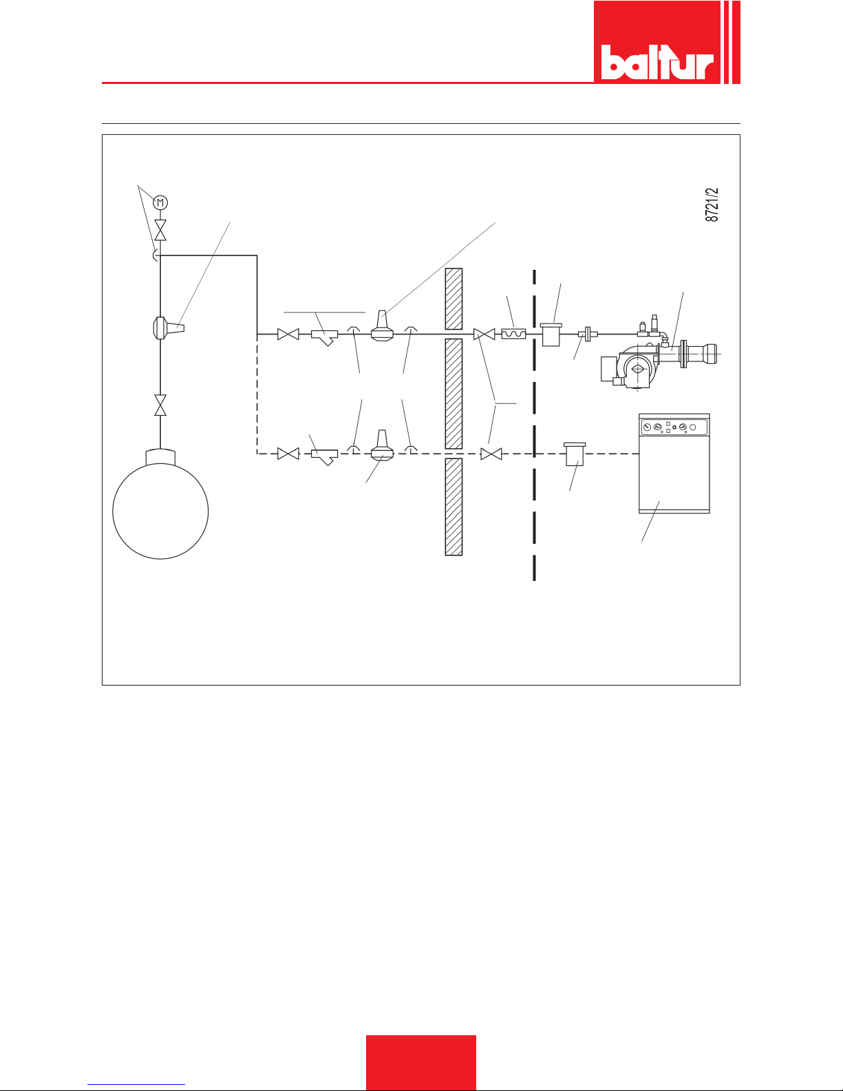
SCHEMA DI PRINCIPIO PER RIDUZIONE PRESSIONE G.P.L. A DUE STADI PER BRUCIATORE OPPURE CALDAIA
Manometro e presa di
pressione
Serbatoio G.P.L.
Riduttore di 1° salto
Uscita ~ 1,5 bar
Portata ~ il doppio del massimo richiesto
dall’utilizzatore
Riduttore di 2° salto
Uscita ~ 30 mbar
Portata ~ il doppio del massimo richiesto
dall’utilizzatore
Filtro a Y
Filtro
Filtro
Presa di pressione
Riduttore di 2° salto
Uscita ~ 30 mbar
Portata ~ il doppio del massimo richiesto
dall’utilizzatore
Filtro a Y
Rubinetto a
sfera
Giunto
antivibrante
Bruciatore
Caldaia a pavimento o murale
Raccordo
FORNITO DAL COSTRUTTORE
A CURA DELL’INSTALLATORE
ITALIANO
26 / 30
0006080763_201611
Page 29
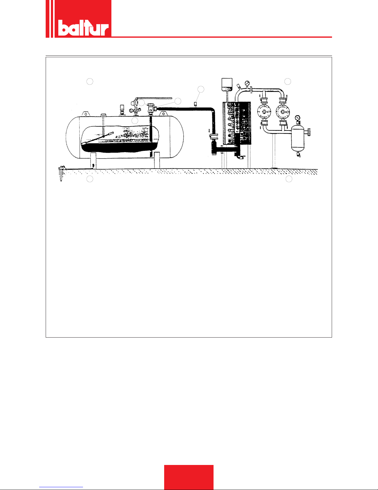
SCHEMA DI INSTALLAZIONE CON VAPORIZZATORE
3
2
1
4
Vaporizzatore
A
C
B
D
A Eventuale collegamento fase gas di emergenza
B Vaporizzatore
C Serbatoio
D Gruppo riduzione 1° salto
Avvertenze
• Il vaporizzatore è considerato punto pericoloso, pertanto va posto
a distanza di sicurezza dai fabbricati.
• L’impianto elettrico deve essere AD-PE (anti deagrante - prova
esplosione).
• Le tubazioni del GPL devono essere in acciaio SS con giungzioni
saldate o angiate PN 40 (pressione nominale 40 bar). Sono vietate le giunzioni mediante lettature.
Specica materiali
• Valvola di ripresa liquido
• Rubinetto erogazione liquido con limitatore di usso.
• Raccordi in acciaio con codolo a saldare e rondella rame.
• Valvola di sicurezza a 18 bar con raccordo in acciaio a saldare.
ITALIANO
27 / 30
0006080763_201611
Page 30

ISTRUZIONI PER L'ACCERTAMENTO DELLE CAUSE DI IRREGOLARITÀ NEL FUNZIONAMENTO E LA LORO ELIMINAZIONE
IRREGOLARITÁ
L'apparecchio va in "blocco" con
amma (lampada rossa accesa).
Guasto circoscritto al dispositivo di
controllo amma.
L'apparecchio va in "blocco", il gas
esce, ma la amma non è presen-
te (lampada rossa accesa).Guasto
circoscritto al circuito di accensione.
L'apparecchio va in "blocco", il gas
esce, ma la amma non è presente
(lampada rossa accesa).
POSSIBILE CAUSA
1 Disturbo della corrente di ionizza-
zione da parte del trasformatore di
accensione.
2 Sensore amma (sonda ionizzazio-
ne) inefciente.
3 Sensore di amma (sonda ionizza-
zione) in posizione non corretta.
4 Sonda ionizzazione o relativo cavo
a massa.
5 Collegamento elettrico interrotto del
sensore di amma.
6 Tiraggio inefciente o percorso fumi
ostruito.
7 Disco amma o testa di combustio-
ne sporchi o logori.
8 Apparecchiatura guasta.
9 Manca ionizzazione.
1 Guasto nel circuito di accensione.
2 Cavetto trasformatore d'accensione
scarica massa.
3 Cavetto d'accensione scollegato.
4 Trasformatore d'accensione guasto.
5 La distanza tra l'elettrodo e massa
non è corretta.
6 Isolatore sporco e quindi l'elettrodo
scarica massa.
1 Rapporto aria/gas non corretto.
2 La tubazione del gas non è stata
adeguatamente sfogata dall'aria
(caso di prima accensione).
3 La pressione del gas è insufciente
o eccessiva.
4 Passaggio aria tra disco e testa
troppo chiuso.
RIMEDIO
1 Invertire l'alimentazione (lato 230V) del
trasformatore di accensione e vericare
con micro-amperometro analogico.
2 Sostituire il sensore amma.
3 Correggere la posizione del sensore di
amma e, successivamente, vericarne
l'efcienza inserendo il micro-ampero-
metro analogico.
4 Vericare visivamente e con strumento.
5 Ripristinare il collegamento.
6 Controllare che i passaggi fumo caldaia/
raccordo camino siano liberi.
7 Vericare visivamente ed eventualmen-
te sostituire.
8 Sostituirla.
9 Se la "massa" dell'apparecchiatura non
è efciente non si verica la corrente di
ionizzazione.Vericare l'efcienza della
"massa" all'apposito morsetto dell'appa-
recchiatura e al collegamento a "terra"
dell'impianto elettrico.
1 Vericare l'alimentazione del trasfor-
matore d'accensione (lato 230V) e
circuito alta tensione (elettrodo a massa
o isolatore rotto sotto il morsetto di
bloccaggio).
2 Sostituirlo.
3 Collegarlo.
4 Sostituirlo.
5 Metterlo alla corretta distanza.
6 Pulire o sostituire l'isolatore e l'elettrodo.
1 Correggere il rapporto aria/gas (proba-
bilmente c'è troppa aria o poco gas).
2 Sfogare ulteriormente, con le dovute
cautele, la tubazione del gas.
3 Vericare il valore della pressione gas
al momento dell'accensione (usare
manometro ad acqua, se possibile).
4 Adeguare l'apertura disco/testa.
ITALIANO
28 / 30
0006080763_201611
Page 31
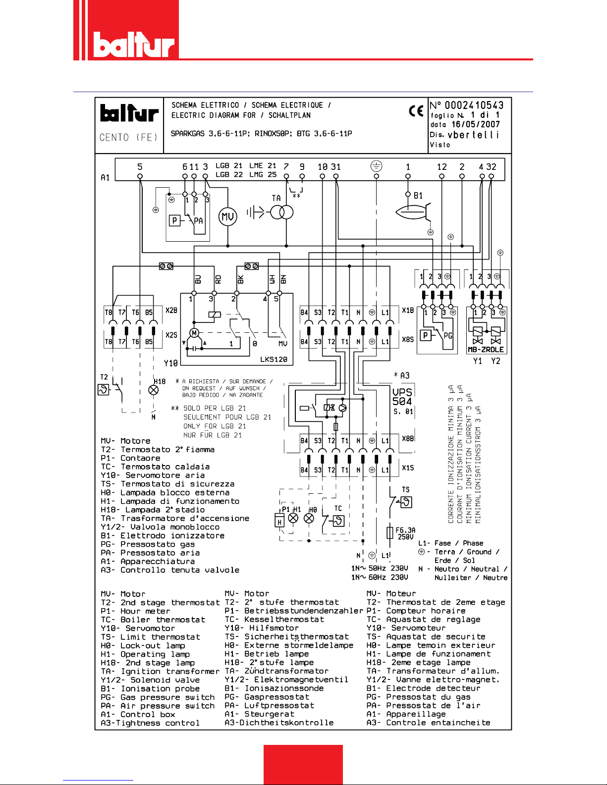
SCHEMI ELETTRICI
ITALIANO
29 / 30
0006080763_201611
Page 32

A1 APPARECCHIATURA
A3 CONTROLLO TENUTA VALVOLE
B1 FOTORESISTENZA / ELETTRODO DI IONIZZAZIONE /
FOTOCELLULA UV
H0 SPIA BLOCCO ESTERNA / LAMPADA FUNZIONAMEN-
TO RESISTENZE AUSILIARIE
H1 SPIA DI FUNZIONAMENTO
H18 “SPIA FUNZIONAMENTO 2° STADIO“
MV MOTORE VENTOLA
PA PRESSOSTATO ARIA
P1 “CONTAORE“
PG PRESSOSTATO GAS
T2 “TERMOSTATO 2 STADIO“
TA TRASFORMATORE D’ACCENSIONE
TC TERMOSTATO CALDAIA
TS TERMOSTATO DI SICUREZZA
Y1/Y2 ELETTROVALVOLE 1° / 2° STADIO
Y10 SERVOMOTORE ARIA
Colore serie li
GNYE VERDE / GIALLO
BU BLU
BN BRUNO
BK NERO
BK* CONNETTORE NERO CON SOVRASTAMPA
L1 - L2- L3 Fasi
N - Neutro
** A rchiesta
Terra
ITALIANO
30 / 30
0006080763_201611
Page 33

ENGLISH
INDEX
Instructions for use in safe conditions .....................................................................................................................................................3
Technical specications ........................................................................................................................................................................... 6
Supplied material...............................................................................................................................................................................7
Burner identication plate .................................................................................................................................................................. 7
First start up recording data ..............................................................................................................................................................7
Operating range ................................................................................................................................................................................8
Overall dimensions ............................................................................................................................................................................ 9
Component description ...................................................................................................................................................................10
Burner connection to the boiler .............................................................................................................................................................. 11
Electrical connections ............................................................................................................................................................................ 12
Operating description ............................................................................................................................................................................13
Starting up and regulation .....................................................................................................................................................................13
Air regulation on the combustion head ............................................................................................................................................ 15
Ionization current ............................................................................................................................................................................. 15
Control and command equipment LME... .............................................................................................................................................. 16
CONNECTRON “LKS 120-02 (B5-5-51) AIR DUMPER CONTROL SERVOMOTOR ...........................................................................19
Diagram for regulation of combustion head and electrode disk distance ........................................................................................ 20
Maintenance .......................................................................................................................................................................................... 23
Maintenance time ............................................................................................................................................................................ 24
Specications for propane use .............................................................................................................................................................. 25
Diagram illustrating the principle of L.P.G. pressure reduction in two stages for burner or boiler ...................................................26
INSTALLATION DIAGRAM WITH VAPORIZER ..............................................................................................................................27
Troubleshooting instructions ..................................................................................................................................................................28
Wiring diagrams .....................................................................................................................................................................................29
ENGLISH
1 / 30
0006080763_201611
Page 34

DECLARATION OF CONFORMITY
CE0085:
DVGW CERT GmbH, Josef-Wirmer Strasse 1-3-53123 Bonn (D)
We hereby declare under our own responsibility, that our domestic and industrial blown air burners red by gas, oil and dual fuel, series:
BPM...; BGN…; BT…; BTG…; BTL…; TBML...; Comist…; GI…; GI…Mist; Minicomist…; PYR…; RiNOx…; Spark...; Sparkgas...;
TBG...;TBL...; TS…; IBR...; IB...
(Variant: … LX, for low NOx emissions)
respect the minimal regulation of the European Directives:
• 2009/142/CE (D.A.G.)
• 2004/108/CE (C.E.M.)
• 2006/95/CE (D.B.T.)
• 2006/42/CE (D.M.)
and compliant with the European Standards:
• prEN 676:2012 (gas and dual fuel, gas side)
• prEN 267:2012 (diesel and dual fuel, diesel side)
• EN 60335-1 (2012-01) + EC (2014-01) (all burners)
Cento, 12 Genuary 2015
Director of Research & Development
Paolo Bolognin
Managing Director and General Manager
Riccardo Fava
ENGLISH
2 / 30
0006080763_201611
Page 35

INSTRUCTIONS FOR USE IN SAFE CONDITIONS
PURPOSE OF THE MANUAL
The manual purpose is to contribute to the safe use of the product,
indicating the conduct and behaviour required to prevent alterations to the safety features of the apparatus which could derive
from incorrect installation or incorrect, unauthorised or unreaso-
nable uses.
The manufacturer is not liable contractually or extra contractually
for any damage caused by errors in installation and in use, or
where there has been any failure to follow the manufacturer’s in-
structions.
• The machines produced have a minimum life of 10 years, if the
normal working conditions are respected and if periodic mainte-
nance specied by the manufacturer is made.
• The instruction booklet is an integral and essential part of the
product and must be given to the user.
• The user must keep the booklet with care for any future con-
sultation.
• Carefully read the “Instruction for use” in this manual and
the instructions indicated on the product before using the
equipment in order to minimise risks and avoid accidents.
• Follow the SAFETY INSTRUCTIONS carefully. Avoid IMPRO-
PER USES.
• The installer must assess RESIDUAL RISKS that might remain.
• Symbols are used to draw your attention to some parts of the
text or to indicate some important precautions. Their meaning
is described below.
DANGER / CAUTION
This symbol indicates a serious danger, that if ignored, can
seriously put at risk the health and safety of the operator.
CAUTION / WARNING
This symbol indicates that a proper conduct must be adopted in order not to put at risk the health and safety of people
and cause economic damage.
IMPORTANT
This symbol indicates particularly important technical and
operational information.
CONDITIONS AND DURATION OF STORAGE
The equipment is shipped with the manufacturer package and
transported on road, by boat or by train in compliance with the
standards on goods transport in force for the actual mean of transport used.
The unused equipment must be placed in closed rooms with
enough air circulation in standard conditions (temperature betwe-
en -10° C and + 40° C).
The storage time is 3 years.
GENERAL INSTRUCTIONS
• The equipment production date (month, year) is written on the
burner identication plate located on the equipment.
• The device is not suitable to be used by persons (including chil-
dren) with reduced physical, sensory or mental capacities, or
lack of experience or knowledge.
• such persons can use the device only if they can benet, throu-
gh the intermediation of a responsible person, of information
regarding their safety, of surveillance, of instructions concerning
its use.
• Children should be supervised to ensure that they do not play
with the device.
• This appliance should only be used for the purpose it has been
designed for. Any other use is to be considered improper and
therefore dangerous.
• The equipment must be installed in accordance with current
regulations, following the manufacturer’s instructions and by
qualied technicians.
• The term ‘qualied personnel’ refers to personnel specically
trained and with proven skills in the eld of heating according to
the local legislation in force.
• An incorrect installation can cause injury or damage to persons,
animals and objects, for which the manufacturer cannot be held
responsible.
• After removing all the packaging make sure the contents are
complete and intact. If in doubt do not use the equipment and
return it to the supplier. The packing is potentially dangerous
and must be kept away from children.
• The majority of the equipment components is made of reusable
material. The package and the equipment cannot be disposed
of with the standard waste but according to the regulations in
force.
• Before carrying out any cleaning or maintenance, disconnect
the equipment at the mains supply, using the system’s switch
and/or shut-off systems.
• If the equipment is sold or transferred to another owner or if the
owner moves and leaves the equipment, make sure that the
booklet always goes with the equipment so it can be consulted
by the new owner and/or installer.
• With the equipment operating do not touch the hot parts usually
located near the ame or the fuel pre-heating system, if present.
These parts can remain hot even after a non prolonged stop of
the equipment.
• For all equipment with optionals or kits (including electrical
ones), only original accessories must be used.
ENGLISH
3 / 30
0006080763_201611
Page 36

• If there is any fault and/or if the equipment is not working pro-
perly, de-activate the equipment and do not attempt to repair it
or tamper with it directly. Contact only qualied personnel.
• Any product repairs must only be carried out by BALTUR autho-
rised assistance centres or its local retailer using only original
spare parts.
• The manufacturer and/or its local retailer decline any liability
for injuries or damage caused by unauthorised modications of
the product or non-observance of the instructions contained in
the manual.
SAFETY INSTRUCTIONS FOR INSTALLATION
• The equipment must be installed in a suitable area with ade-
quate ventilation according to the standards and regulations in
force.
• The slots of the air extraction grilles and installation room venti-
lation openings must not be obstructed even partially.
• In the installation site there must NOT be any risk of explosion
and/or re.
• Thoroughly clean the inside of all pipes of the fuel supply sy-
stem before installation.
• Before connecting the burner check that the details on the plate
correspond to those of the utility supplies (electricity, gas, diesel
or other fuel).
• Make sure that the burner is rmly fastened to the heat genera-
tor according to the manufacturer's instructions.
• Make the connections to the power sources properly as indi-
cated in the explanatory diagrams and following the standards
and regulations in force at the moment of installation.
• Check that the fume exhaust system is NOT obstructed.
• If you decide not to use the burner any more, the following pro-
cedures must be performed by qualied technicians:
- Switch off the electrical supply by disconnecting the power
cable from the main switch.
- Cut off the fuel supply using the shut-off valve and remove
the control wheels from their position.
- Render harmless any potentially dangerous parts.
INSTRUCTIONS FOR START-UP, INSPECTION, USE AND
MAINTENANCE
• Start-up, inspection and maintenance of the equipment must
only be carried out by qualied technicians, in compliance with
current regulations.
• Once you have fastened the burner to the power generator,
make sure that during testing the ame produced does not
come out of any slots.
• Check for the seal of fuel supply pipes connected to the equipment.
• Check that the fuel ow rate matches the power required by
the burner.
• Set the burner fuel capacity to the power required by the heat
generator.
• The fuel supply pressure must lie between the values indicated
on the data plate located on the burner and/or in the manual
• The fuel supply system is suitably sized for the ow required
by the thermal module and that it has all the safety and control
devices required by current standards.
• Before starting up the burner, and at least once a year, have
qualied technicians perform the following procedures:
- Set the burner fuel capacity to the power required by the
heat generator.
- Check the combustion adjusting the comburent and/or fuel
air ow to optimise the combustion performance and emissions according to the regulations in force.
- Check the regulation and safety devices are working
properly.
- Check for the correct operation of the combustion products
exhaust duct.
- Check for the seal of fuel supply pipes in their internal and
external parts.
- At the end of the adjustment procedures, check that all
the mechanical locking devices of regulation systems are
properly tightened.
- Make sure that the burner use and maintenance manual are
available and within your reach.
• If the burner repeatedly shuts down in lock-out, do not keep
trying to manually reset it but call a qualied technician to solve
the unexpected problem.
• If you decide not to use the burner for a while, close the valve or
valves that supply the fuel.
ENGLISH
4 / 30
0006080763_201611
Page 37

Special instructions for using gas.
• Check that the feed line and the train comply with current standards and regulations.
• Check that all the gas connections are properly sealed.
• Do not leave the equipment on when it is not in use and always
close the gas cock.
• If the user is away for some time, close the main gas feed valve
to the burner.
• If you smell gas:
- do not operate electrical switches, the phone or any other
object that can cause sparks;
- immediately open doors and windows to create a draught to
clear the air in the room;
- close the gas cocks;
- have professionally qualied personnel correct the fault.
• Do not block ventilation openings in the room where there is gas
equipment or dangerous situations may arise with the build up
of toxic and explosive mixtures.
RESIDUAL RISKS
• In spite of the accurate product planning according to the regu-
lations in force, residual risks may still be present during correct
use. They are indicated on the burner by means of specic Pi-
ctograms.
CAUTION
Mechanical parts in motion.
CAUTION
Materials at high temperatures.
CAUTION
Energised electrical switchboard
INSTRUCTIONS ON ELECTRICAL SAFETY
• Check that the equipment is properly grounded according to the
safety standards in force.
• Do not use the gas pipes to ground electrical equipment.
• If in doubt, call for a careful electrical check by a qualied tech-
nician, since the manufacturer will not be liable for any damage
caused by a poor ground connection.
• A professional check should be carried out to ensure that the
electrical installation is adequate for the maximum output absorbed by the system. This is indicated on the data plate.
• Make sure that the system cable cross-section is suitable for
the power absorbed by the equipment.
• The use of adaptors, multiple plugs and/or extension leads to
supply power from the mains to the appliance is not allowed.
• For the connection to the mains, t an omnipolar switch with a
contact opening gap equal to or greater than 3 mm in accordance with current safety regulations (Overvoltage category III).
• Use only double insulated cables with external thickness of at
least 1mm for the power supply of the burner.
• Unsheathe the external insulating cover of the power cable to
the necessary extent for the connection, thus avoiding the wire
from coming into contact with metal parts.
• The electrical supply to the burner must have neutral to ground
connection. In the case of a ionisation current check with neu-
tral not to ground, it is essential to make a connection between
terminal 2 (neutral) and the ground for the RC circuit.
• If the user is away for some time, close the main gas feed valve
to the burner.
• The use of any components that use electricity means that certain fundamental rules have to followed, including the following:
- do not touch the equipment with parts of the body that are
wet or damp and/or with damp feet
- do not pull on electrical cables;
- do not leave the equipment exposed to atmospheric agents
(such as rain or sun etc.) unless there is express provision
for this.
- do not allow the equipment to be used by children or inexperienced persons.
- The power supply cable for the equipment not must be
replaced by the user. If the cable is damaged, turn off the
equipment. To replace the cable, contact exclusively qualied personnel.
- If you decide not to use the equipment for a while it is advisable to switch off the electrical power supply to all components in the system that use electricity (pumps, burner, etc.).
ENGLISH
5 / 30
0006080763_201611
Page 38

TECHNICAL SPECIFICATIONS
MODEL BTG 3,6P BTG 6P BTG 11P
MAXIMUM NATURAL GAS HEAT POWER
kW
41.9 56.3 99
MINIMUM NATURAL GAS HEAT POWER
kW
16.3 30.6 48.8
¹) NATURAL GAS EMISSIONS
mg/kWh
Class 2 Class 2 Class 2
OPERATION Two-stage Two-stage Two-stage
NATURAL GAS TRANSFORMER 50 Hz 15kV - 25mA 15kV - 25mA 15kV - 25mA
NATURAL GAS TRANSFORMER 60 Hz 15kV - 25mA 15kV - 25mA 15kV - 25mA
MAXIMUM NATURAL GAS HEAT RATE
Stm³/h
4.2 5.7 10
MINIMUM NATURAL GAS HEAT RATE
Stm³/h
1.6 3.1 4.9
MAXIMUM NATURAL GAS PRESSURE
mbar
360 360 360
NATURAL GAS MINIMUM PRESSURE
mbar
19 20 20
PROPANE GAS MAXIMUM THERMAL POWER
kW
41.9 56.3 99
PROPANE GAS MINIMUM THERMAL POWER
kW
16.3 30.6 48.8
PROPANE GAS MAXIMUM HEAT CAPACITY
Stm³/h
1.63 2.2 3.87
PROPANE GAS MINIMUM HEAT CAPACITY
Stm³/h
0.64 1.2 1.9
PROPANE GAS MAXIMUM PRESSURE
mbar
360 360 360
PROPANE GAS MINIMUM PRESSURE
mbar
30 30 30
²)PROPANE EMISSIONS
mg/kWh
Class 2 Class 2 Class 2
50 Hz FAN MOTOR
kW
0.11 0.11 0.11
50Hz FAN MOTOR RPM
r.p.m.
2800 2800 2800
60Hz FAN MOTOR
kW
0.11 0.11 0.11
60Hz FAN MOTOR RPM
r.p.m.
3300 3300 3300
ABSORBED ELECTRICAL POWER* 50Hz
kW
0.11 0.11 0.11
ABSORBED ELECTRICAL POWER* 60Hz
kW
0.11 0.11 0.11
50 Hz POWER SUPPLY VOLTAGE 1N~ 230V ± 10% 1N~ 230V ± 10% 1N~ 230V ± 10%
60 Hz POWER SUPPLY VOLTAGE 1N~ 220V ± 10% 1N~ 220V ± 10% 1N~ 220V ± 10%
DEGREE OF PROTECTION IP40 IP40 IP40
FLAME DETECTOR IONISATION PROBE IONISATION PROBE IONISATION PROBE
EQUIPMENT LME21.. LME21.. LME21..
SOUND PRESSURE**
dBA
64 64 64
WEIGHT WITH PACKING
kg
12 12 12
WEIGHT WITHOUT PACKING
kg
10.75 10.75 10.75
Caloric power lower than reference conditions 15° C, 1013 mbar:
Natural gas: Hi = 9.45 kWh/Stm³ = 34.02 MJ/Stm³
Propane gas: Hi = 24.44 kWh/Stm³ = 88.00 MJ/Stm³
For different types of gas and pressure values, please contact our sales department.
Minimum gas pressure, depending on the type of gas train used for obtaining max. ow rate with null pressure in the combustion cham-
ber.
* Total absorption at start with ignition transformer on.
The measurements have been carried out in accordance with EN 15036 - 1 standard.
** The acoustic pressure measured with burner operating at maximum rated thermal output refers to the manufacturer's laboratory
environment conditions and cannot be compared to measurements carried out in different locations.
*** Acoustic power was obtained characterizing the manufacturer's laboratory with a sample source; this measurement has a class 2
accuracy (engineering class) with a standard deviation of 1.5 dB(A).
CO emissions, natural gas/propane ≤ 100 mg/kWh
ENGLISH
6 / 30
0006080763_201611
Page 39
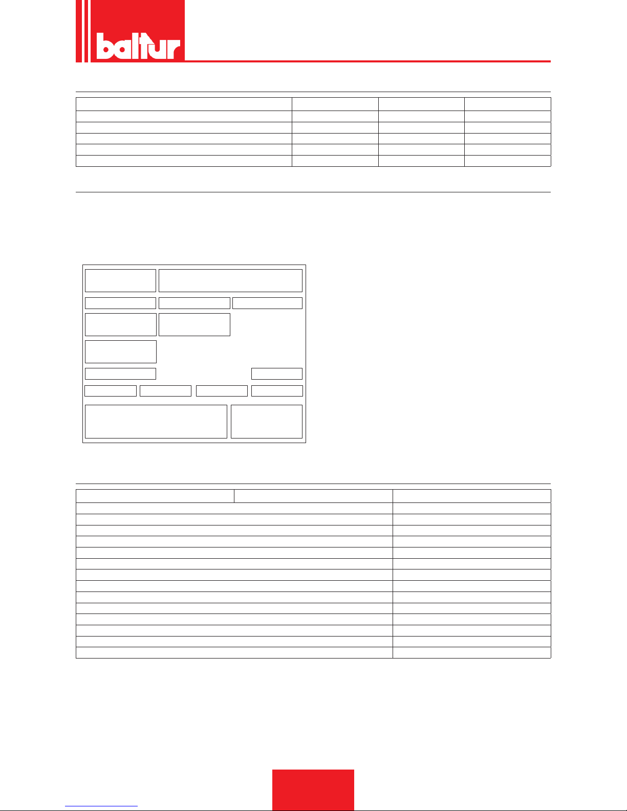
SUPPLIED MATERIAL
MODEL BTG 3,6P BTG 6P BTG 11P
BURNER CONNECTION FLANGE 1 1 1
INSULATING SEAL 1 1 1
STUD BOLTS N°4 M8 No. 4 x M8 No. 4 x M8
HEXAGONAL NUTS N°4 M8 No. 4 x M8 No. 4 x M8
FLAT WASHERS No. 4 Ø 8 No. 4 Ø8 No. 4 Ø8
BURNER IDENTIFICATION PLATE
1 2
3 4 5
6 7
11
14
12
Targa_descr_bru
8
9
10 13
1615
1 Company logo
2 Company name
3 Product code
4 Model
5 Serial number
6 Liquid fuel power
7 Gas fuel power
8 Gas fuel pressure
9 Liquid fuel viscosity
10 Fan motor power
11 Power supply voltage
12 Protection rating
13 Country of manufacture and homologation certicate numbers
14 Year of manufacture
15 -
16 Burner serial number bar code
FIRST START UP RECORDING DATA
Model: Date: Now:
Type of gas
Lower Wobbe number
Lower caloric power
Gas ow
Stm3/h
Min. gas ow rate
Stm³/h
Max. gas ow rate
Stm³/h
Min. gas power
kW
Max. gas power
kW
Network gas pressure
mbar
Gas pressure downstream of the stabiliser
mbar
CO
CO2
fume temperature
air temperature
ENGLISH
7 / 30
0006080763_201611
Page 40
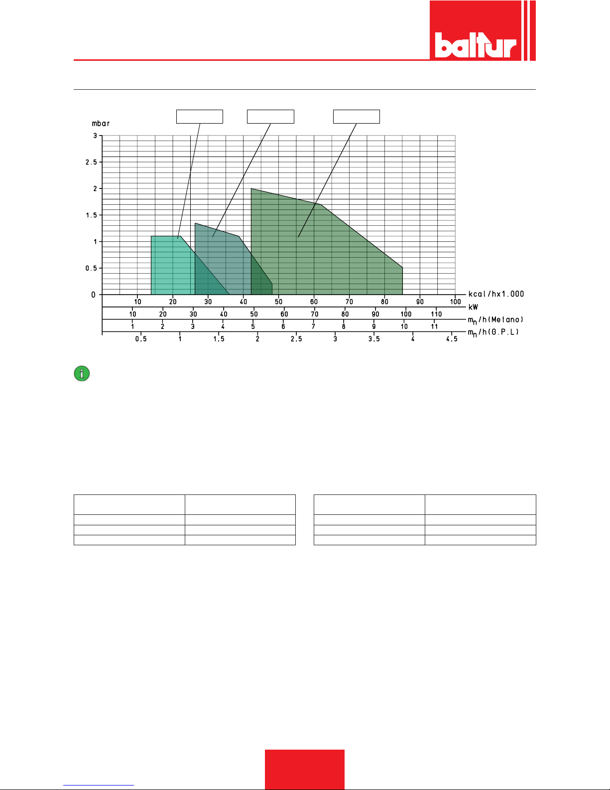
OPERATING RANGE
BTG 3,6 - 3,6P BTG 6 - 6P BTG 11 - 11P
IMPORTANT
The operating ranges are obtained from test boilers corresponding to Standard EN676 and are indicative of the burner-boiler combination. For correct working of the burner the size of the combustion chamber must correspond to current regulations; if not the
manufacturers must be consulted.
The burner should not work outside the indicated work range.
¹) NATURAL GAS EMISSIONS
Classes dened according to Standard EN 676.
Class
NOx emissions in mg/kWh -
natural gas
1 ≤ 170
2 ≤ 120
3 ≤ 80
²) PROPANE EMISSIONS
CO emissions, natural gas/propane ≤ 100 mg/kWh
Class
NOx emissions in mg/kWh -
propane gas
1 ≤ 230
2 ≤ 180
3 ≤ 140
ENGLISH
8 / 30
0006080763_201611
Page 41
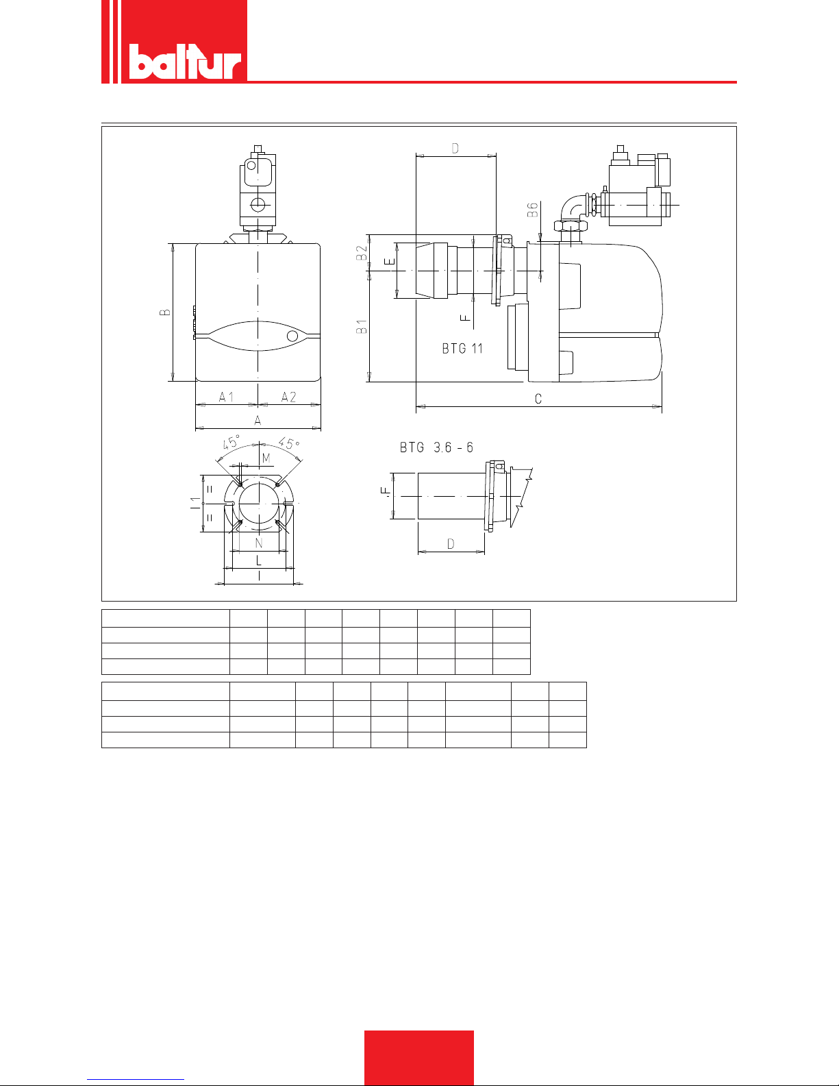
OVERALL DIMENSIONS
0002470861
Model A A1 A2 B B1 B2 B6 C
BTG 3,6P 246 123 123 289 219 70 53 410
BTG 6P 246 123 123 289 219 70 53 410
BTG 11P 246 123 123 289 219 70 53 475
Model D E Ø F Ø I I LØ M N Ø
BTG 3,6P 50 ÷ 105 90 90 170 140 130 ÷ 155 M8 95
BTG 6P 50 ÷ 105 90 90 170 140 130 ÷ 155 M8 95
BTG 11P 90 ÷ 150 108 90 170 140 130 ÷155 M8 95
ENGLISH
9 / 30
0006080763_201611
Page 42
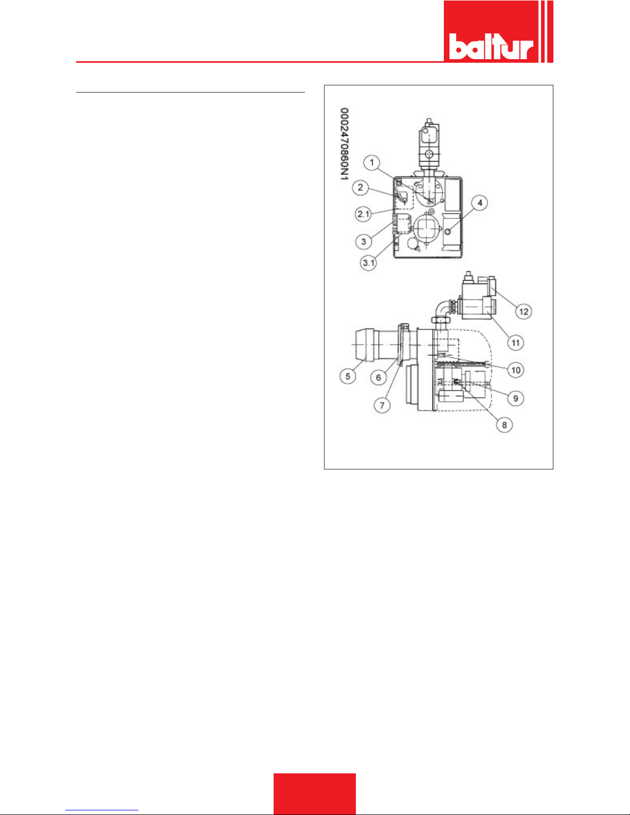
COMPONENT DESCRIPTION
1 Reference for disk - head positioning
2 Air damper opening adjustment screw
3 7-pole connector
4 4-pole connector
5 Control box
6 Combustion head
7 Insulating gasket
8 Burner connection ange
9 Motor
10 Air pressure switch
11 Disk head regulating screw
12 Gas solenoid valve
13 Minimum gas pressure switch
ENGLISH
10 / 30
0006080763_201611
Page 43
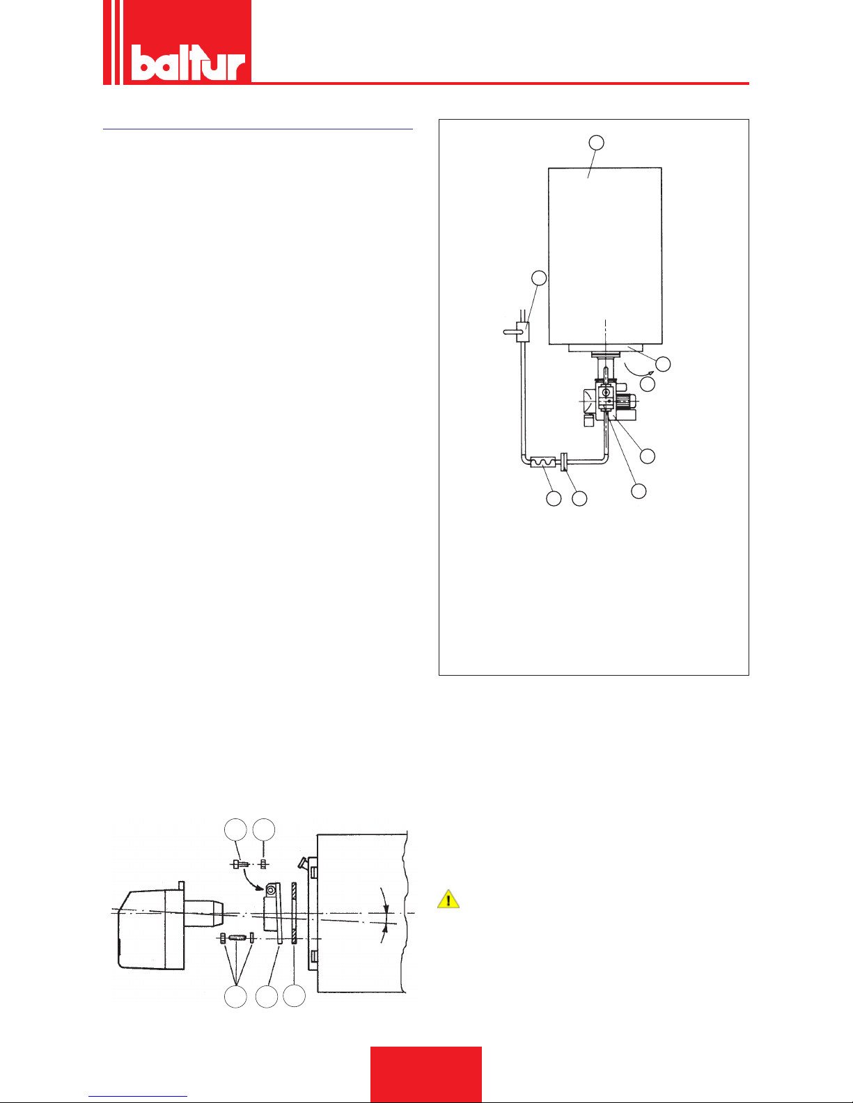
BURNER CONNECTION TO THE BOILER
The gas supply pipe must be suitably sized for the pipe length and
gas output according to the UNI Standard. It must be perfectly
airtight and properly checked before testing the burner.
It is essential to install on this piping, near the burner, a suitable
tting to allow an easy disassembly of the burner and/or the opening of the boiler door.
The burner is equipped with a coupling ange which slips on the
combustion head.
When applying the burner to the boiler, it is necessary to correctly
position the ange so that the burner head enters the furnace to
the extent specied by the boiler manufacture.
When the burner has been correctly applied to the boiler, connect
it to the gas pipeline.
If the gas valve incorporates a lter and a gas pressure stabilizer,
only a shut-off cock and an anti-vibration joint have to be tted
onto the gas pipeline.
Only in the event the gas pressure is higher than the maximum level permitted by the Standards, a suitable pressure reducer must
be installed on the gas pipeline outside the heating plant.
Install an elbow directly on the burner gas pipe before applying
the removable tting, so as to allow the boiler door, if installed,
opening after opening the tting itself.
1
2
3
4
5
67
8
8871
1 Boiler
2 Door
3 Door opening direction
4 Burner
5 DUNGS monobloc gas valve
6 Fitting
7 Vibration-proof joint
8 Gate valve
9
7
19
13
0002932940
5
A
• Apply the isolating seal -13 between the ange that fastens the
burner and the boiler plate.
• Fasten the ange -19 to the boiler using the stud bolts with their
nuts and washers -7.
• Insert the burner into the ange and tighten the screw -5 with
the nut -9.
DANGER / CAUTION
When xing the burner to the ange, position the combustion head axis as illustrated in the diagram (angle A).
ENGLISH
11 / 30
0006080763_201611
Page 44

ELECTRICAL CONNECTIONS
• Observe applicable national and European Standards (e.g. EN
60335-1/EN 50165) regarding electrical safety.
• Gas models, with detection electrode, are equipped with a devi-
ce that recognises the polarity.
• Failure to respect the phase-neutral polarity causes a non vo-
latile lock out at the end of the safety time. In the event of a
'partial' short circuit or poor isolation between the line and earth,
the voltage on the detection electrode may be reduced until it
causes the equipment to lock out, given that the ame signal
fails to be detected.
• Carefully check the cables before commissioning.
• Incorrect wiring can damage the equipment and jeopardise sy-
stem safety.
• Makes sure the equipment earth terminal, the metal burner ca-
sing and electrical system earthing are connected properly.
• Avoid laying the detection cable along with the power cables or
ignition cables.
• Use a cable and detection electrode capable of withstanding
heat. They should also be well insulated and protected against
condensation or water in general.
• Use a shorter and straight ignition cable and lay it far from other
conductors to minimise radio interferences
• (maximum length less than 2 m and isolation voltage > 25 kV).
• This equipment has internal fuses, however, it must be pro-
tected by means of at least one fuse on the line connection.
ENGLISH
12 / 30
0006080763_201611
Page 45

OPERATING DESCRIPTION
By closing the main switch, if the thermostats are closed, voltage
will reach the command and control equipment and, after a short
time, the burner will start up according to its pre-established pro-
gram.
The fan motor will then be turned on and, when it starts functioning, it will bring about a pre -washing of the combustion chamber.
Subsequently, ignition activates and, after three seconds, the safety valve and the operating (main) valve will open.
The presence of the ame, detected by the relevant control devi-
ce, permits continuation and completion of ignition.
In case of ame failure, the equipment activates a “safety shut
down” within 3 seconds of the opening of the gas valves (operating and safety).
In “safety lock-out” mode the valves are closed again immediately.
To reset the equipment from its safety position, press the red release button on the equipment.
STARTING UP AND REGULATION
Verify the combustion chamber does not contain gas before any
ignition operation.
In case of three-phase burner, check that the motor rotation direction is correct.
• Check that there is water in the boiler and that the gate valves
of the system are open.
Purge the air contained in the gas pipeline, if it had not been
carried out when connecting the burner to the gas pipeline. As a
precaution, special care should be taken and doors and windows
should be opened.
Wait until you smell gas, and then close the valve.
Open the union on the pipe near the burner and then open the gas
shut-off valves a little way.
• Check that the discharge of combustion products through the
boiler gate and ue gate take places freely.
• Open the combustion air regulator as necessary and open approx. a third of the passage of air between disk and head.
• Operate the regulators incorporated in the safety and operating
valve in such a way as to obtain the gas delivery presumed
necessary.
• Deactivate the second stage thermostat to prevent it from being
activated, and power up the burner switching the main switch
on.
• The burner is therefore activated and carries out the pre-ventilation phase.
• If the air pressure exceeds that value at which the air pressure
switch has been set, the ignition transformer will be connected
and, subsequently, the gas valves (safety and 1st ame) will be
inserted.
• The valves open completely and the gas delivery is limited to
the position at which the ow regulator incorporated in the main
operating valve has been manually regulated.
• Upon rst switching on, repeated “lock outs” may occur due to:
• The gas pipeline has not been adequately purged of air and
therefore the quantity of gas is not sufcient to allow for a stable
ame.
• “Lock out” with ame presence could be caused by ame in-
stability in the ionisation area, due to an incorrect air/gas ratio.
• This can be solved by changing the amount of air and/or gas
supplied, so as to nd the right ratio.
• This problem could also be caused by an incorrect distribution
of air/gas in the combustion head.
• This can be solved through the combustion head adjustment
device, by closing or opening further the air passage between
the combustion head and the gas diffuser, using the ame disk
adjustment system.
• It may occur that the ionisation current is disturbed by the discharge current of the ignition transformer (the two currents
have a common path on the burner’s “mass”). Therefore, the
burner locks out due to an insufcient ionisation.
• This can be solved by inverting the input (230V side) of the igni-
tion transformer (the places of the two wires that give voltage to
the transformer are exchanged).
• This problem may also be caused by an insufcient “ground
connection” of the burner’s casing.
• We must point out that the minimum value of the ionisation cur-
rent to ensure the operation of the equipment is shown on the
wiring diagram.
• With the burner running, adjust delivery to the desired value for
“rst ame by reading it on the meter.
• The ow rate can be changed using the regulator incorporated
in the valve, as described above.
• Check that combustion occurs correctly by using the appropriate instruments (CO2 max= about 10% for natural gas - CO max.
= 0.1%).
• After this adjustment, switch the burner off and on again a few
times to check if ignition is correct.
ENGLISH
13 / 30
0006080763_201611
Page 46
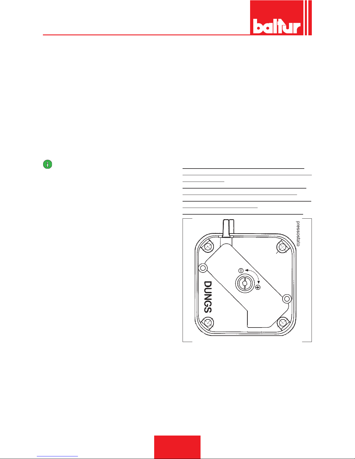
• With the burner turned off from the main switch, connect the
second ame thermostat directly.
• Open also the gas ow rate regulator integrated in the second
valve so as the necessary output for the main ame is enabled.
• Now close the main switch to start up the burner.
• When the burner is lit with the second ame, it is necessary to
check as previously shown, the gas ow and the combustion
with the appropriate instruments.
• On the basis of checks carried out, change, if necessary, the
gas delivery and the related combustion air in order to adjust
the delivery to the desired value according to specic case (boi-
ler power).
• Check the combustion parameters with appropriate instruments
(CO2 MAX=10% O2 MIN= 3% CO MAX=0.1%)
• Check the efciency of the safety devices, block devices (by
unplugging the ionisation electrode cable), air pressure switch,
gas pressure switch and thermostats.
IMPORTANT
The pressure switch connection circuit is self controlling.
Therefore, the contact which is meant to be closed in a non
operating state (fan stopped and thus no air pressure in burner), should in fact be in this state, otherwise the command/
control equipment will not be switched on (burner remains
inoperative).
• It must be specied that if the contact is not closed during wor-
king, the control box will carry out its cycle, but the ignition transformer will not be inserted and the gas valves will not open.
Consequently, the burner will go to shut down.
• Check that the air pressure switch functions properly with burner operating, increase the regulating value until it reaches in-
tervention point and the burner should go to shut down.
• Reset the burner by pressing the appropriate button and readjust the pressure switch to a value that allows you to detect the
air pressure during the preventilation stage.
AIR PRESSURE SWITCH
The air pressure switch stops the equipment operation if air pressure is not at the expected value.
The pressure switch must therefore be adjusted so that it is triggered to close the NO contact (normally open) when the air pressure
in the burner reaches a particular value.
If the air pressure switch does not detect a pressure greater than
that calibrated, the equipment runs through its cycle but does not
switch on the ignition transformer and does not open the gas val-
ves and so the burner “locks-out”.
To ensure the air pressure switch correct operation, with burner at
the minimum output, increase the adjustment value until reaching
the triggering value which must be followed by the immediate burner lock-out.
Release the burner by pressing the appropriate button and readjust the pressure switch until preventilation air pressure can be
detected.
Air pressure sampling point is upstream the air shutters.
Regulate the air pressure switch after rst carrying out all the
other burner adjustments with the air pressure switch adjusted to
the start of the scale.
With the burner operating at a low ow rate (1st ame), slowly
turn the central screw clockwise until the burner locks out.
Then give the screw a half-turn anti-clockwise and repeat burner
start-up to check for proper operation.
If the burner locks out again give the screw another half-turn.
ENGLISH
14 / 30
0006080763_201611
Page 47
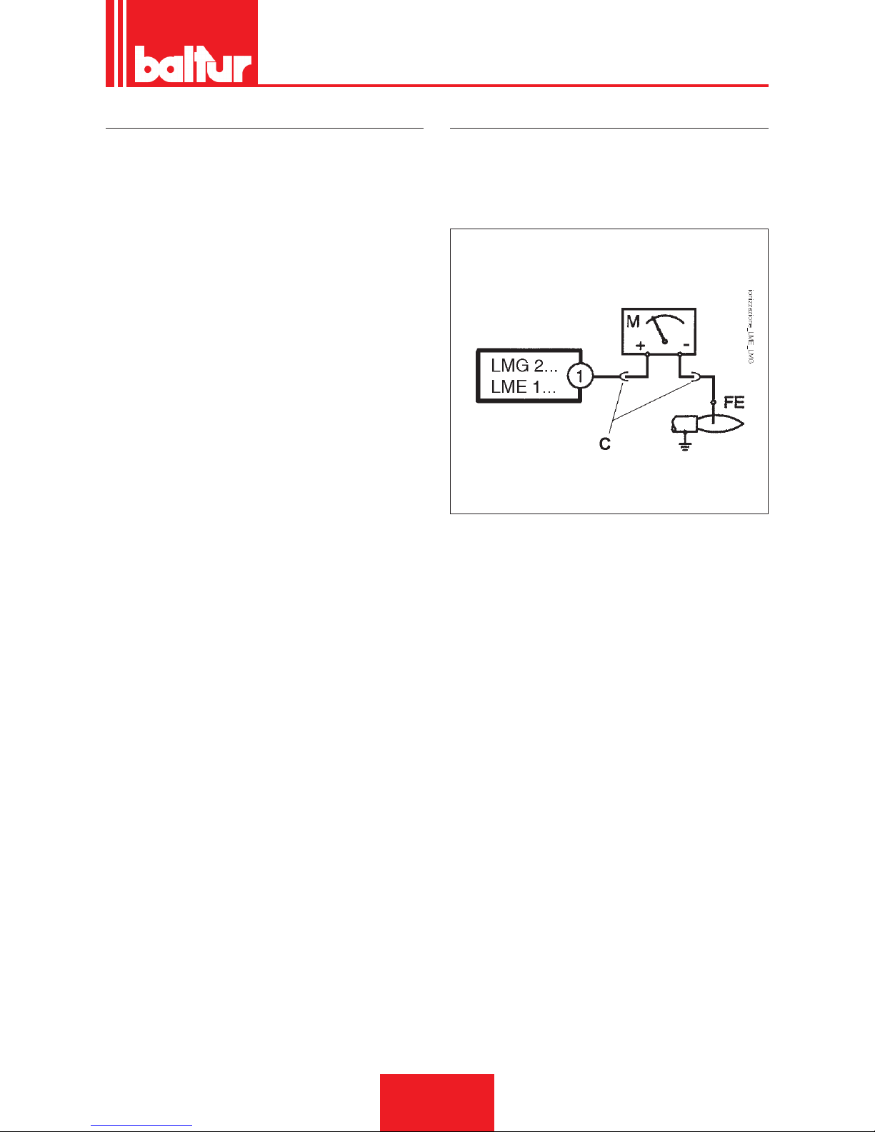
AIR REGULATION ON THE COMBUSTION HEAD
The combustion head has a regulation device that allows the air
passage between the disc and the combustion head to be opened
or closed.
You are thus able to obtain, closing the passage, high pressure
upstream of the disk even at low ow rates.
The high speed and turbulence of the air provides for its greater
penetration into the fuel and therefore an excellent mixture and
ame stability.
High air pressure upstream of the disk may be necessary to
prevent ame uctuations, this is particularly essential when the
burner works on the furnace that is pressurised and/or at a high
thermal load.
Therefore, the air regulation device on the combustion head
should be put in such a position as to always obtain a decidedly
high air pressure value behind the disk.
In order to achieve this, you need to secure the device in an inter-
mediate position on the head air closure and use the air damper
device to increase the ow to the fan intake. Obviously, this condition must occur when the burner is working at the maximum power
required by the system.
Correct the position of the device that closes the air of the combustion head, moving it forward or backward, in order to obtain an air
ow suitable for the supply with the air damper considerably open.
When reducing the air passage on the combustion head, make
sure not to close it completely.
Check that the ignition occurs correctly. If the head opens excessively, it could cause strong air turbulence leading to difcult ignition.
IONIZATION CURRENT
The minimum ionisation current needed to run the equipment is 3
µA.The burner ame generates a signicantly higher current, which usually does not require any control by the equipment.Should
the ionisation current need to be measured, a microammeter must
be connected in series to the ionisation electrode lead by opening
the connector “C”, see wiring diagram.
ENGLISH
15 / 30
0006080763_201611
Page 48
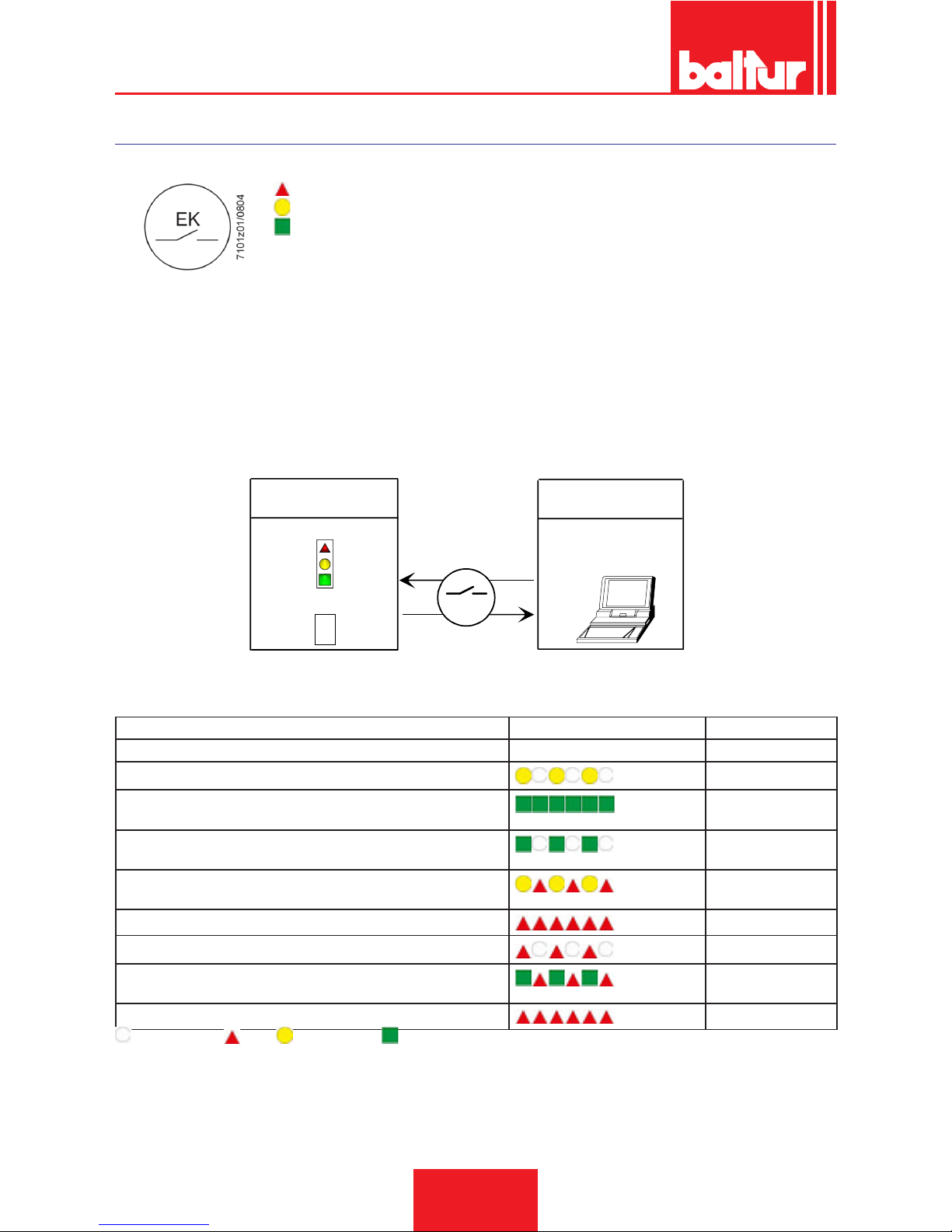
CONTROL AND COMMAND EQUIPMENT LME...
OPERATION.
RED
YELLOW
GREEN
The reset button «EK...» is the main element to access all diagnostic functions (activation and deactivation), and serves to unlock the command
and control device.
Both «LED» and «EK...» are positioned under the transparent button. Pressing this button, you can reset the control box.
Possibility of two diagnostic functions:
1. Visual indication directly on the reset button: operation and diagnostics of device status.
2. Diagnostics with interface: in this case the OCI400 connecting cable is necessary and it can be connected to a PC with ACS400 softwa-
re, or to gas analysers of different manufacturers
VISUAL INDICATION.
During operation, the command and control equipment phase is indicated on the reset button. The table lists all colour sequences and
their meaning. To activate the diagnostics function, hold the reset button down for at least 3 seconds. A quick red ashing indicates that
the function is active. Likewise, hold the reset button down for at least 3 seconds to deactivate the function (the switching will be indicated
with a ashing yellow light).
EK
xxxxxxxx
xxxxxxxx
xxxxxxxx
xxxxxxxx
xxxxxxxx
xxxxxxxx
> 3 s
7101z03e0305
Operating position
PC interface/diagnostic
analyser
Colour code table
Diagnostics
Operating position
COMMAND AND CONTROL DEVICE STATUS INDICATION.
Condition Colour sequence Colours
Waiting conditions TW, other intermediate statuses . . . . . . . . No light
Ignition phase
Intermittent yellow
Correct operation, current strength of ame detector above the minimum allowed
Green
Incorrect operation, current strength of ame detector below the minimum allowed
Intermittent green
Decrease in power supply voltage
Alternating Yellow
and Red
Burner in lock condition
Red
Fault indication (see colour legend)
Intermittent red
Extraneous light upon burner start-up
Alternating Green
and Red
Quick ashing for diagnostics
Quick ashing red
NO LIGHT. RED. YELLOW. GREEN.
ENGLISH
16 / 30
0006080763_201611
Page 49
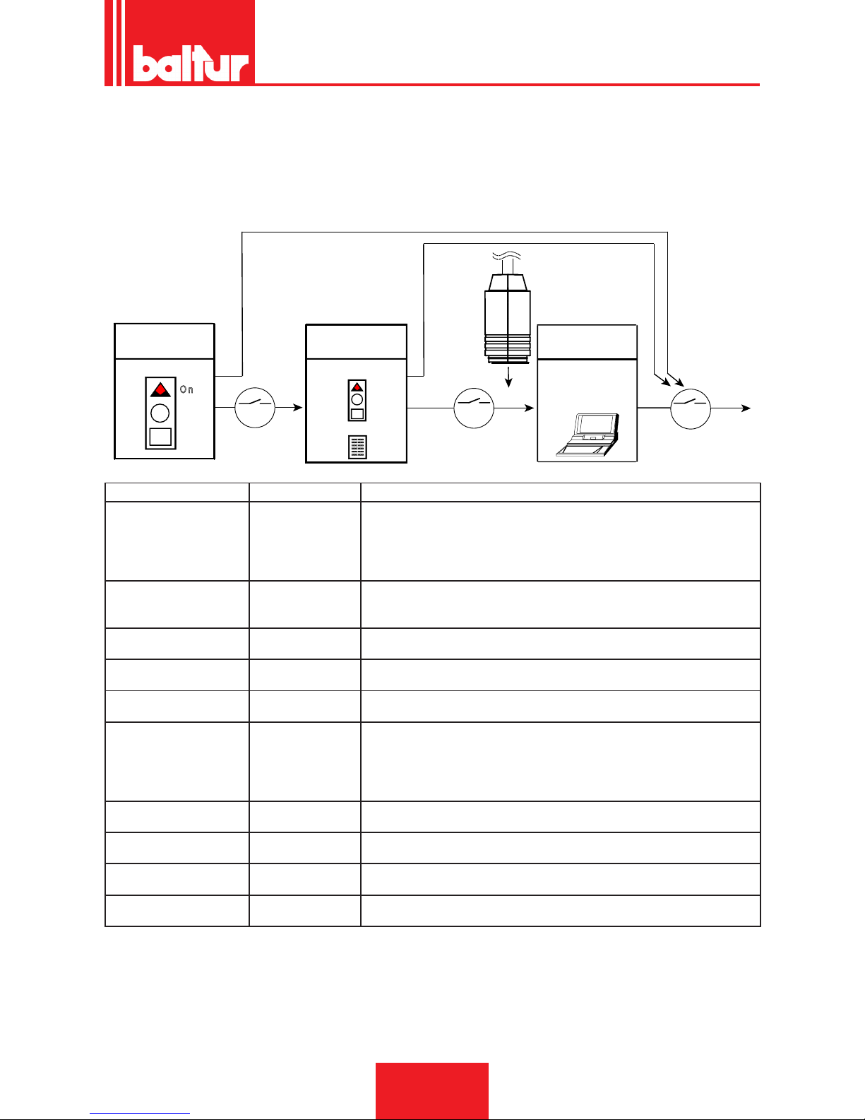
MALFUNCTION AND LOCK CAUSE DIAGNOSTICS.
In the event of a burner lock-out, the red light on the reset button will be xed.
Keeping it pressed in for more than 3 seconds, the diagnostics procedure is activated (red light with quick ashes). The table below indicates the meaning of the lock-out or failure according to the number of red ashes.
Holding the reset button down for at least 3 seconds, the diagnostics function will be interrupted.
The diagram below shows the operations to be carried out to activate the diagnostic functions even with communication interface through
the "OCI400" connection cable.
E K
> 3 s
xxxxxxxx
xxxxxxxx
xxxxxxxx
xxxxxxxx
xxxxxxxx
xxxxxxxx
E K
OCI400
E K
< 3 s
7101z04e0305
R e s e t
O n
> 3 s
Operating position
Operating position
Visual indication
Colour code table
Operating position
PC / analyser
interface
diagnostics
Visual indication AL to terminal 10 Possible causes
2 blinks
●●
On No ame at the end of the safe ignition time<TSA>
- Faulty or soiled fuel valves
- Faulty or soiled ame detector
- Poor adjustment of burner, no fuel
- No ignition Faulty ignition transformer
3 blinks
●●●
On - Defective LP air pressure switch
- No or faulty air pressure signal after completion "t10"
- LP pressure switch contact welded in standby position
4 blinks
●●●●
On Extraneous light during the ignition phase
5 blinks
●●●●●
On - No air pressure switch signal
- LP pressure switch contact welded in work position
6 blinks
●●●●●●
On Not used
7 blinks
●●●●●●●
On No ame signal during normal operation, ignition repetition (limitation of ignition
repetitions)
- Malfunction of the fuel valves
Faulty or soiled ame detector
- Poor adjustment of burner
8 blinks
●●●●●●●●
On Not used
9 blinks
●●●●●●●●●
On Not used
10 blinks
●●●●●●●●●●
On Wiring problems or damage inside the device
14 blinks
●●●●●●●●●●●●●●
On CPI contact not closed
• During the time the cause of fault is diagnosed, the control outputs are deactivated.
• - Is the burner shut down?
• - The alarm signal AL “is on terminal 10 which is under voltage.
• Press the lockout reset button for about 1 second (< 3 seconds) to reactivate the device and start a new cycle.
ENGLISH
17 / 30
0006080763_201611
Page 50
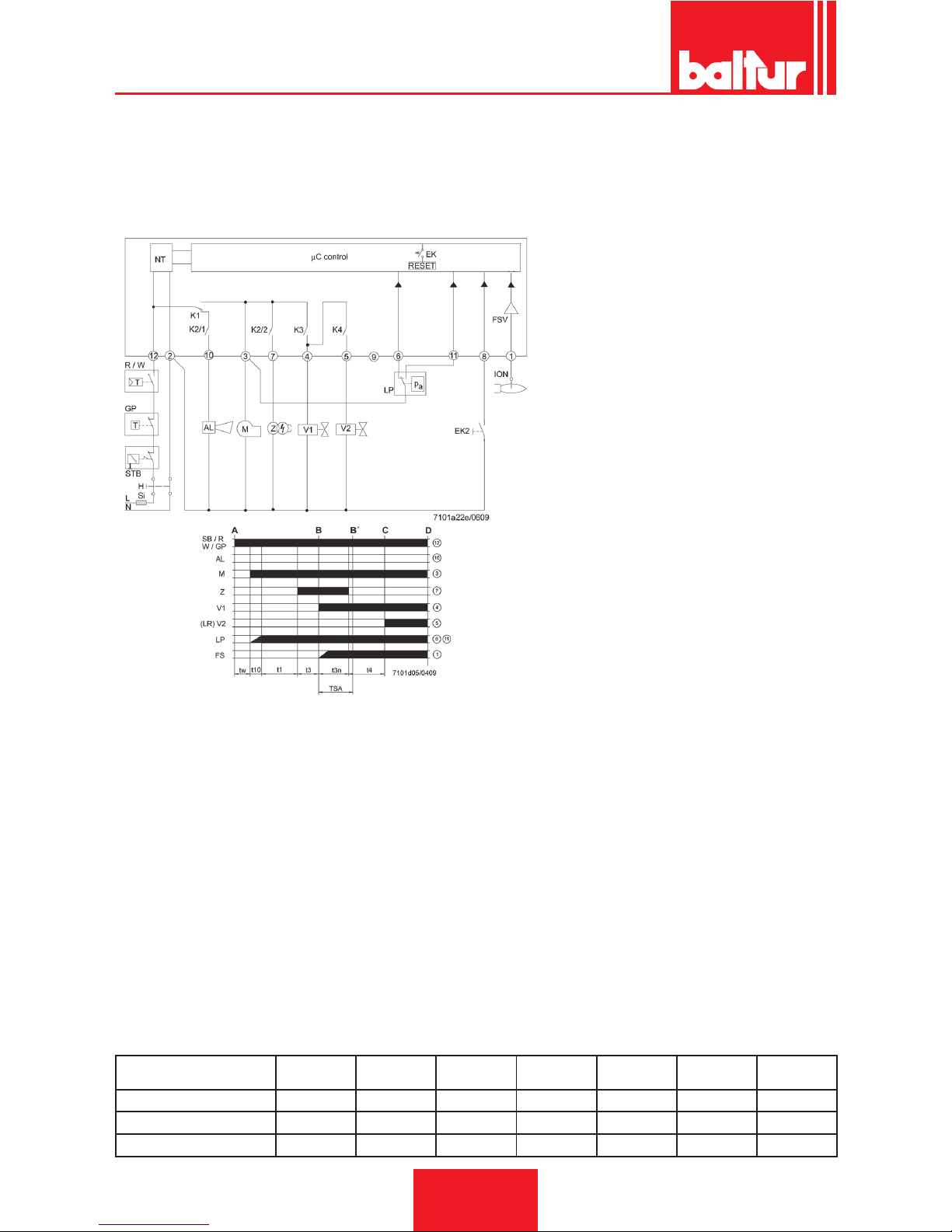
WIRING DIAGRAM AND OPERATION CONTROL SEQUENCE OF EQUIPMENT LME 21...(WHEN USING THE CONNECTION WITH SOME ACTUATORS, IT IS NECESSARY TO COMPLY WITH THE REQUIREMENTS OF
EN 676)
I 1st Actuator cam
t1 Preventilation time
t1´ Ventilation time
t3 Pre-ignition time
t3n After-ignition time
t4 Interval between ignition «Off» and release of «BV2»
t10 Available time for detecting the air pressure of the pressure switch
t11 Programmed opening time for actuator «SA»
t12 Programmed closing time for actuator «SA»
t22 2° safety time
TSA Ignition safety time
tw Waiting time
AGK25... PTC resistance
AL Error message (alarm)
BCI Burner Communication Interface
BV... Fuel Valve
CPI Closed Position Indicator
Dbr.. Wiring jumper
EK.. Remote lockout reset button (internal)
EK2 Remote lockout reset button
ION Ionisation probe
FS Flame Signal
FSV Flame signal amplier
GP Gas pressure switch
H Main switch
HS Auxiliary contactor, relay
ION Ionisation probe
K1...4 Internal Relays
KL Low ame
LK Air damper
LKP Air damper position
LP Air pressure switch
LR Modulation
M Fan motor
MS Synchronous motor
NL Rated load
NT Electric power supply
QRA... Flame Detection
QRC… Blue-ame detector bl blue br brown sw black
R Control thermostat / pressure switch
RV Gas adjustment device
SA SQN Actuator...
SB Safety limit thermostat
STB Safety limit thermostat
Si External fuse
t Time
W Limit thermostat / Pressure switch
Z Ignition transformer
ZV Pilot gas valve
A_tab_Start-up Command (ignition from «R»)
B-B´ Interval for ame ignition
C Burner in operation position
C-D Burner operation (generation of heat)
D Shut-down controlled by «R»
Burner will be immediately shut down
Burner control will be immediately ready for new start-up
Equipment or program-
mer
TSA t1 t3 t3n t4 t11 t12
s s s s s s s
LME 21,350 C2 5 30 2 4,5 10 - -
LME 21,430 C2 3 40 2 2,5 8 - -
ENGLISH
18 / 30
0006080763_201611
Page 51
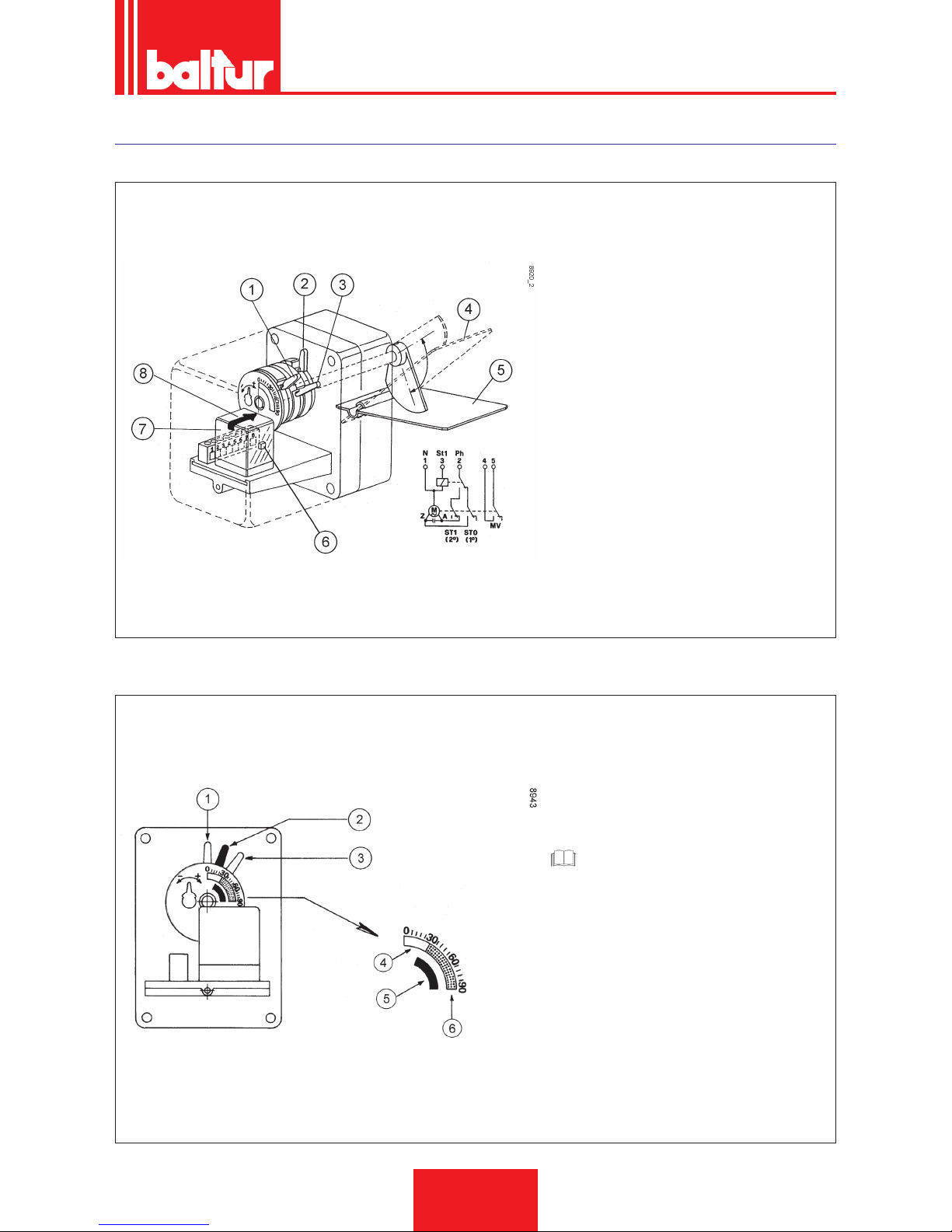
CONNECTRON “LKS 120-02 (B5-5-51) AIR DUMPER CONTROL SERVOMOTOR
AIR DAMPER CLOSED WHEN BURNER NOT OPERATING.
1) 2nd ame valve activation cam (black) must be in
an intermediate position between cams that regulate
the 1st and 2nd ame air
2) 1st ame air regulation cam (light blue)
3) 2nd ame air regulation cam (red)
4) Air damper in open position
5) Air damper in closed position
6) Button for 2nd ame manual control
7) Rotation direction inversion relay
8) Servomotor index reference.
1 Neutral
2 Phase
3 2nd ame thermostat
4/5 Micro switch for 2nd ame valve
ADJUSTMENT FOR SERVOMOTOR FIRST IGNITION
For the rst ignition, adjust the cams preliminarily as
follows:
1) 2nd ame valve activation cam (black) 40°
2) 1st ame air regulation cam (light blue) 25°
3) 2nd ame air regulation cam (red) 50°
4) Light blue
5) Black
6) Red
CAUTION / WARNING
The cam position must be adjusted to the effective fuel output, verifying the combustion
with specic instruments.
Air ow rate in the 1st ame position must correspond to at least 50% of the total air ow.
ENGLISH
19 / 30
0006080763_201611
Page 52
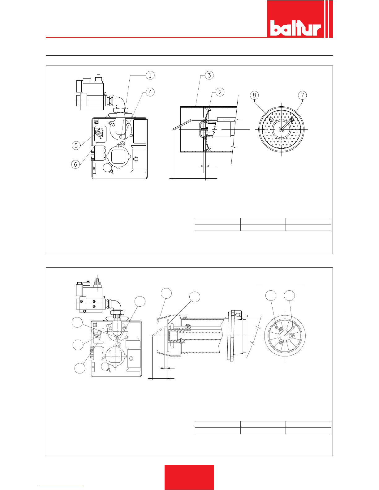
DIAGRAM FOR REGULATION OF COMBUSTION HEAD AND ELECTRODE DISK DISTANCE
BTG 3.6 - 6P
A
B
0002933473
1Disc-head adjustment screw (screw to open the air passage
between the disc and the head, unscrew to close)
2 - Disc: Attention: do not close completely
3 - Combustion head
4 - Disc-head reference position
5 - Manual air regulation system
6 - Air regulation servomotor only for BTG 3,6P- 6P
7 - Ionisation electrode
8 - Ignition electrode
A - Max ignition electrode projection
B - Ionisation electrode projection
A B
**non tradotto** 1 0+1 56 ±1
BTG 11P
1
5
6
4
3
2
7 8
A
B
0002936370
1Disc-head adjustment screw (screw to open the air passage
between the disc and the head, unscrew to close)
2 - Disc: Attention: do not close completely
3 - Combustion head
4 - Disc-head reference position
5 - Manual air regulation system
6 - Air regulation servomotor only for BTG 11
7 - Ignition electrode
8 - Ionisation electrode
A - Max ignition electrode projection
B - Ionisation electrode projection
A B
BTG 11P 7 ±1 52 ±1
ENGLISH
20 / 30
0006080763_201611
Page 53
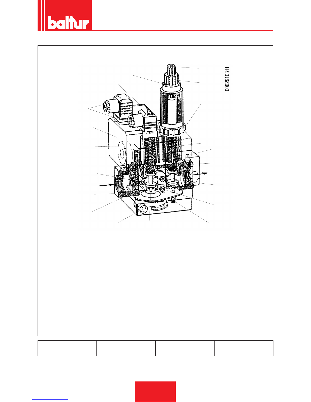
COMBINED GAS VALVE (MONOBLOC) DUNGS MODEL MB-DLE ...
1
2
2
A
3
4
5
16
6
17
12
13
5 (Pa)
7 (Pa)
14
15
8
9
10
11
B
A Electric connections
B Flow direction
1_tab_Locking screw for 1st and 2nd ame regulators
2 Pressure stabiliser adjustment screw cover
3 (Minimum) gas pressure switch
4 Safety valve
5 Gas inlet pressure plug
6 Filter
7 Pressure plug after the pressure stabiliser (Pa)
8 Main valve (1st and 2nd ame)
9 First ame ow adjustment ring
10 Second ame ow adjustment knob
11 Protection cap (using the knob) of the adjustment device of
the initial rapid release.
12 Pressure stabilizer
13 Plug
14 Outlet ange
15 Valve output pressure plug
16 Inlet ange
17 Pressure stabiliser vent
Valve model Max intake pressure (PE) mbar
Stabiliser pressure adjustable at
outlet (PA) mbar
Type of gas used
MB … … B01 S 20 360 from 4 to 20 Natural gas / L.P.G.
ENGLISH
21 / 30
0006080763_201611
Page 54
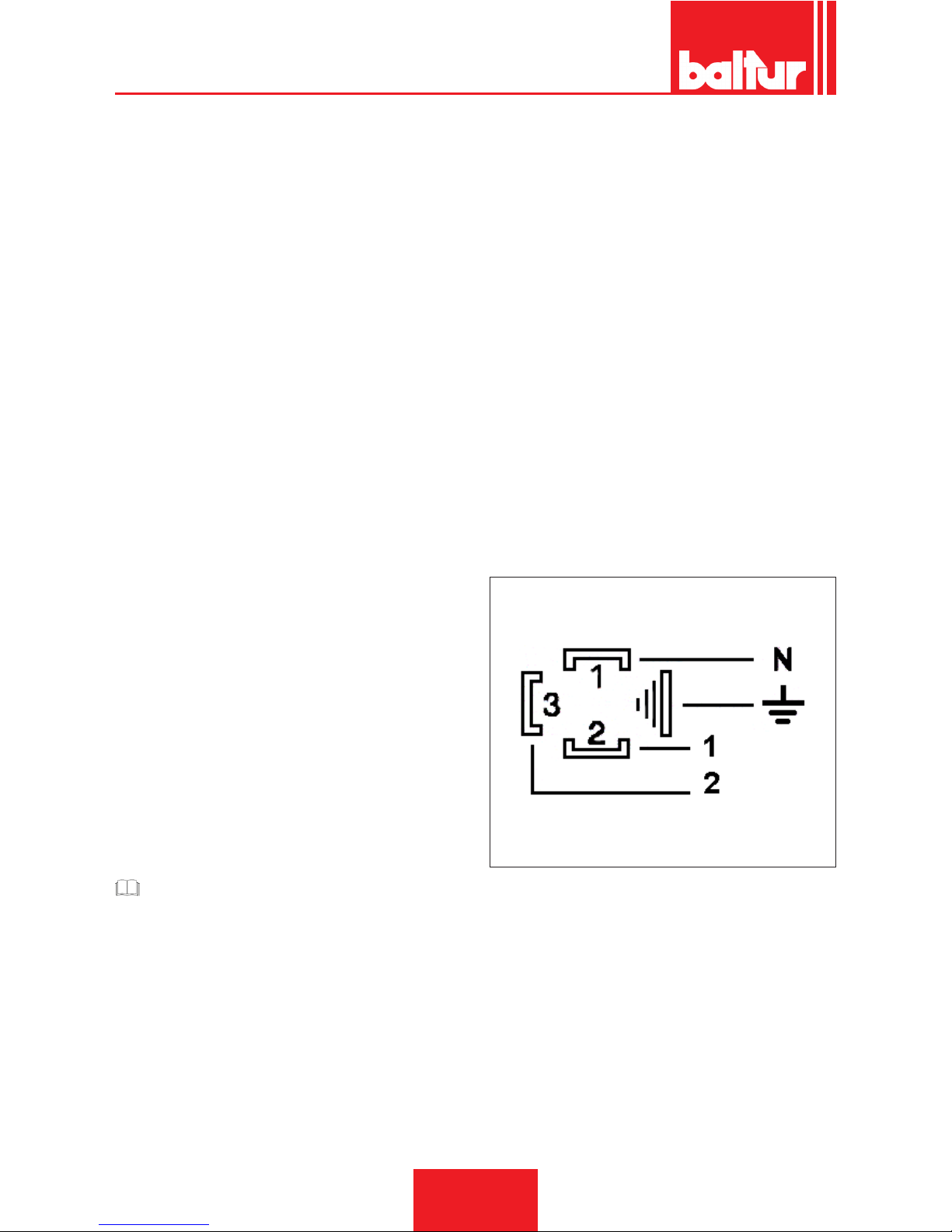
The DUNGS MB-DLE... gas valve unit is made up of:
• Minimum gas pressure switch (3)
• Gas lter (6)
• Pressure regulator (stabiliser) (2)
• Quick opening and closing safety valve (built into the pressure
regulator (4)
• Main two position valve (1st ame and 2nd ame) - slow ope-
ning with quick initial adjustable release and quick closing (8)
• Before proceeding with regulation, read the following specications.
• 1) It is possible to reach the gas lter (6) in order to clean it, by
removing one of the two side closing plates
• The pressure stabilisation can be adjusted (see table) using
the screw which can be accessed sliding the cover (2) to one
side.The full stroke from the minimum to the maximum and vice
versa requires 60 full turns. Do not apply force against the limit switches.Before igniting the burner, make at least 15 turns
towards the + sign.Around the access opening there are arrows
with symbols indicating the rotation direction for pressure increase (clockwise) or decrease (anti-clockwise).This stabilizer
creates a hermetic closure between the "upstream" and "downstream" sections when there is no ow.Different springs to
obtain different pressure value from those described above are
not foreseen.To adjust the pressure stabiliser, connect a water
gauge to the hose connection installed on the valve, to the plug
Pa (7) corresponding to the stabiliser outlet.
• Regulation is not foreseen for the quick opening and closing
safety valve (4).
• Main valve (8).
• Regulating the initial rapid release effects the 1st and 2nd opening positions of the valve.The adjustment of rapid release and
hydraulic brake act on the rst and second positions of the valve
in proportion to the ow rate adjustments.To carry out regulation, unscrew the protection cover (11) and use the back part of
it as a tool to turn the pin.
Clockwise rotation = slower quick releaseAnticlockwise rotation =
faster quick release
REGULATING THE FIRST POSITION (1ST FLAME)
• Loosen the screw with the protruding cylindrical head (1).
• Turn the second ame ow rate regulation knob (10) at least
1 turn in the direction indicated by the arrow with the + sign
(anticlockwise).
CAUTION / WARNING
If the 2nd ame regulation knob is not turned at least one
turn towards the +, the valve will not open for the rst po-
sition.
• Turn the rst position adjustment ring (9) to the direction indica-
ted by the arrow + (anti-clockwise rotation).
• As an indication, this should be a little more than two turns from
the end-of-the-stroke position.
• Then, with only the rst ame ignited, turn the ring (9) enough to
obtain the desired gas output for the rst ame.
• The full stoke of the ow regulator (from - to + and vice versa) is
of about THREE turns and a half.
• Rotation of the regulator in a clockwise direction determines a
reduction in th eoutput; rotation in an anti-clockwise direction
increases the output.
SECOND POSITION REGULATION (2ND FLAME)
• Loosen the screw with the protruding cylindrical head (1).
• Rotate the knob (10) in the direction indicated by the arrow for
the + sign (anti-clockwise direction) as much as considered ne-
cessary in order to obtain the gas delivery required for the 2nd
ame.
• The complete stroke of the ow regulator (from - to + and vice
versa) is of about FIVE turns.
• Turning the regulator clockwise will reduce the output, turning it
anticlockwise will increase it.
• After regulating the gas output for the rst and second ame,
remember to tighten the screw (1) to prevent it moving from the
desired position.
DETAILS OF TERMINAL BOARD FOR VALVE MB-ZRDLE
N = neutral
1 = 1st position
2 = 2nd position
ENGLISH
22 / 30
0006080763_201611
Page 55

MAINTENANCE
Analyse combustion gases and check that the emission values
are correct at least once a year, in compliance with current law.
Carry out the following operations at the end of the heating sea-
son:
• Clean air dampers, the air pressure switch with pressure port
and the relevant pipe (if tted).
• Check the electrode condition. Replace them, if necessary.
• Clean the photocell. Replace it, if necessary.
• Have the burner and the chimney cleaned by specialised per-
sonnel (stove repairer); a clean burner is more efcient, lasts
longer and is quieter.
• Check that the fuel lter is clean. Replace it, if necessary.
• Check that all components of the combustion head are in good
condition, have not been deformed and are free from deposits deriving from the installation environment and/or from poor
combustion.
• Analyse combustion gases and check emissions values.
ENGLISH
23 / 30
0006080763_201611
Page 56

MAINTENANCE TIME
COMBUSTION HEAD GAS
ELECTRODES
VISUAL INSPECTION OF THE INTEGRITY OF CERAMICS. TIP GRINDING,
CHECK DISTANCE, CHECK ELECTRICAL CONNECTION.
YEARLY
FLAME DISK INTEGRITY VISUAL INSPECTION FOR POSSIBLE WARPING, CLEANING YEARLY
IONISATION PROBE
VISUAL INSPECTION OF THE INTEGRITY OF CERAMICS. TIP GRINDING,
CHECK DISTANCE, CHECK ELECTRICAL CONNECTION.
YEARLY
COMBUSTION HEAD COMPONENTS INTEGRITY VISUAL INSPECTION FOR POSSIBLE WARPING, CLEANING YEARLY
INSULATING SEAL VISUAL INSPECTION OF LEAK TIGHTNESS AND POSSIBLE REPLACEMENT YEARLY
GAS DELIVERY FITTING GASKET VISUAL INSPECTION OF LEAK TIGHTNESS AND POSSIBLE REPLACEMENT YEARLY
AIR LINE GAS
AIR GRILLE/SHUTTERS CLEANING YEAR
AIR SHUTTER BEARINGS GREASING, (NOTE: apply only to burners with bearings to be greased) 6 MONTHS
AIR PRESSURE SWITCH CLEANING YEAR
AIR PRESSURE PIPES AND OUTLET CLEANING YEAR
SAFETY COMPONENTS GAS
GAS PRESSURE SWITCH OPERATIONAL TEST YEAR
VARIOUS COMPONENTS GAS
ELECTRIC MOTORS (BEARINGS/COO-
LING FAN)
CLEANING, (see if the supplier's indications were provided) YEAR
LEVERS/STRAP SYSTEM/BALL JOINTS
(BACKLASH/LUBRICATION)
CHECK FOR POSSIBLE BACKLASH YEAR
LINE FILTER CLEANING/REPLACEMENT (SPARE CARTRIDGE?) YEAR
COMBUSTION PARAMETERS GAS
TEST OF FUMES ACCORDING TO
BACHARACH INDEXES
COMPARISON WITH THE VALUES RECORDED UPON THE EQUIPMENT START-
UP
YEAR
NOX TEST
COMPARISON WITH THE VALUES RECORDED UPON THE EQUIPMENT START-
UP
YEAR
IONISATION CURRENT TEST
COMPARISON WITH THE VALUES RECORDED UPON THE EQUIPMENT START-
UP
YEAR
FUME TEMPERATURE TESTING
COMPARISON WITH THE VALUES RECORDED UPON THE EQUIPMENT START-
UP
YEAR
GAS PRESSURE REGULATOR PRESSURE MEASUREMENT UPON START-UP YEAR
IMPORTANT
In case of heavy use or particular fuels, the maintenance frequency must be increased and adapted to the use conditions according
to the maintenance technician's indications.
ENGLISH
24 / 30
0006080763_201611
Page 57

SPECIFICATIONS FOR PROPANE USE
• Operating costs approximate assessment;
- 1 m3 of liquid gas in gaseous stage has a lower heating
capacity, of nearly 25.6 kWh.
- To obtain 1 cu.m of gas, about 2 kg of liquid gas are needed,
i.e. about 4 litres of liquid gas.
• Safety provisions
• Liquid propane gas (L.P.G.) in the gaseous form has a greater
specic weight than air (specic weight relative to air = 1.56 for
propane), which means it does not disperse in air like natural
gas, which has a lower specic weight than air (specic weight
of natural gas relative to air = 0.60), but precipitates and spreads out at ground level (as if it were a liquid). Summing up the
concepts we deem most relevant for the use of LPG
• Liqueed petroleum gas (L.P.G.) burners and/or boilers may be
used only in premises located above ground level and certied toward free spaces. Installations using liquid gas are not
allowed in underground or semi-underground premises.
• The rooms in which LPG is used must be tted with adequate
ventilation slots on external walls without closing devices in accordance with the regulations in force.
• Performance of the LPG system to ensure correct and safe
operation.
Natural gasication, from a cylinder bank or tank, can be used
only for systems having low power. The following table gives an
approximate indication of the gas output capacity according to
the tank size and minimum outdoor temperature.
Minimum
tempera-
ture
- 15 °C - 10 °C - 5 °C - 0 °C + 5 °C
990 l tank
1.6 Kg/h 2.5 Kg/h 3.5 Kg/h 8 Kg/h 10 Kg/h
3000 l
tank
2.5 Kg/h 4.5 Kg/h 6.5 Kg/h 9 Kg/h 12 Kg/h
5000 l
tank
4 Kg/h 6.5 Kg/h 11.5 Kg/h 16 Kg/h 21 Kg/h
• Burner;
The burner must be ordered specically for use with liquid
gas (L.P.G.) so that it is equipped with gas valves of sufcient
dimensions to ensure correct ignition and gradual adjustment.
The valve sizing is foreseen for a supply pressure of approximately 300 mbar. You are recommended to check the burner gas
pressure using a pressure gauge.
DANGER / CAUTION
The burner's minimum and maximum output (kW) is rated
based on its use with methane gas which more or less corresponds to the power values obtained with propane gas.
• Combustion testing
To limit consumption and avoid serious trouble, adjust combustion by using the appropriate instruments. It is absolutely essential to check that the percentage of carbon monoxide (CO) does
not exceed the maximum value permitted by the regulations in
force (use a combustion analyser).
ENGLISH
25 / 30
0006080763_201611
Page 58
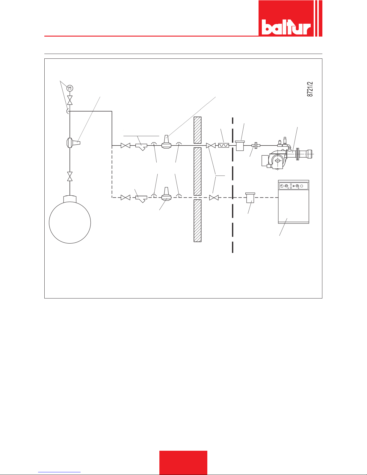
DIAGRAM ILLUSTRATING THE PRINCIPLE OF L.P.G. PRESSURE REDUCTION IN TWO STAGES FOR BURNER OR BOILER
Pressure gauge and pressure
intake
LPG tank
1st step reducer
Output ~ 1.5 bar
Flow rate ~ double the maximum required by the
user
2nd step reducer
Output ~ 30 mbar
Flow rate ~ double the maximum required by
the user
Y lter
Filter
Filter
Pressure intake
2nd step reducer
Output ~ 30 mbar
Flow rate ~ double the maximum required by
the user
Y lter
Ball cock
Vibration-proof
joint
Burner
Free-standing or wall-mounted
boiler
Fitting
SUPPLIED BY THE CUSTOMER
RESPONSIBILITY OF THE INSTALLER
ENGLISH
26 / 30
0006080763_201611
Page 59
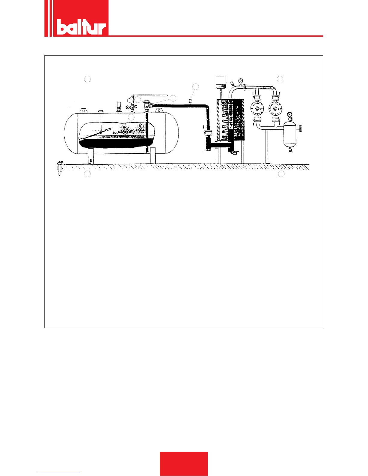
INSTALLATION DIAGRAM WITH VAPORIZER
3
2
1
4
Vaporizzatore
A
C
B
D
A Any emergency gas phase connection
B Vaporizer
C Tank
D 1st stage reducer unit
Warnings
• The vaporizer is considered a dangerous point and should there-
fore be situated at a safe distance from any building.
• The electrical system must be AD-EP (anti-deagration - explosion proof).
• The LPG pipelines must be made of SS steel with welded or an-
ged joints NP 40 (nominal pressure 40 bar). Threaded joints are
prohibited.
Specic materials
• Liquid recovery valve
• Liquid delivery cock with ow limiter.
• Steel tting with welded tang and copper washer.
• 18-bar safety valve with welded steel coupling.
ENGLISH
27 / 30
0006080763_201611
Page 60

TROUBLESHOOTING INSTRUCTIONS
ANOMALY
Appliance locked out due to no ame (red light lit).The fault is in the
ame control device.
The burner goes into “lock-out”,
gas ows, but there is no ame
(red light on).Fault in ignition circuit.
The burner goes into “lock-out”,
gas ows, but there is no ame
(red light on).
POSSIBLE CAUSE
1 Disturbance to ionisation current
from the ignition transformer.
2 Flame sensor (ionisation probe)
inefcient.
3 Flame sensor (ionisation probe)
position incorrect.
4 Ionisation probe or relative ground
cable.
5 Electrical connection cut-off by
ame sensor.
6 Inefcient draught or fumes passa-
ge blocked.
7 Flame disc or combustion heads
dirty or worn.
8 Faulty equipment.
9 No ionisation.
1 Fault in ignition circuit
2 Ignition transformer cable dischar-
ges to earth.
3 Ignition cable disconnected.
4 Ignition transformer faulty.
5 The distance between electrode
and ground is incorrect.
6 Isolator dirty, and electrode dischar-
ges to earth.
1 Air/gas ratio incorrect.
2 Gas pipe has not been properly
bled of air (in the case of rst igni-
tion).
3 The gas pressure is insufcient or
excessive.
4 Air ow between disc and head too
narrow.
REMEDY
1 Invert the ignition transformer power
supply (230V side) and check using an
analogue micro-ammeter.
2 Replace ame sensor.
3 Correct the position of the ame sensor,
and then check for its efciency by con-
necting the analogue micro-ammeter.
4 Check visually and using the instrument.
5 Restore the connection.
6 Ensure that the boiler fumes passage
and chimney connection are free.
7 Visually check and replace, if necessary.
8 Replace it.
9 If the “ground” of the equipment is
not efcient, there is no ionisation
current.Check the efciency of the
“earth” at the terminal concerned in the
equipment and at the “earth” connection
of the electrical system.
1 Check the ignition transformer power
supply (230V) and high voltage circuit
(electrode to earth or isolator broken
under locking terminal).
2 Replace it.
3 Connect.
4 Replace it.
5 Position at the correct distance.
6 Clean or change the isolator or electro-
de.
1 Correct the air/gas ratio (there is pro-
bably too much air or very little gas).
2 Bleed out the gas pipe again, taking
great care.
3 Check the maximum gas pressure
value at the time of ignition (use a water
pressure gauge, if possible).
4 Adjust the disc/head opening.
ENGLISH
28 / 30
0006080763_201611
Page 61
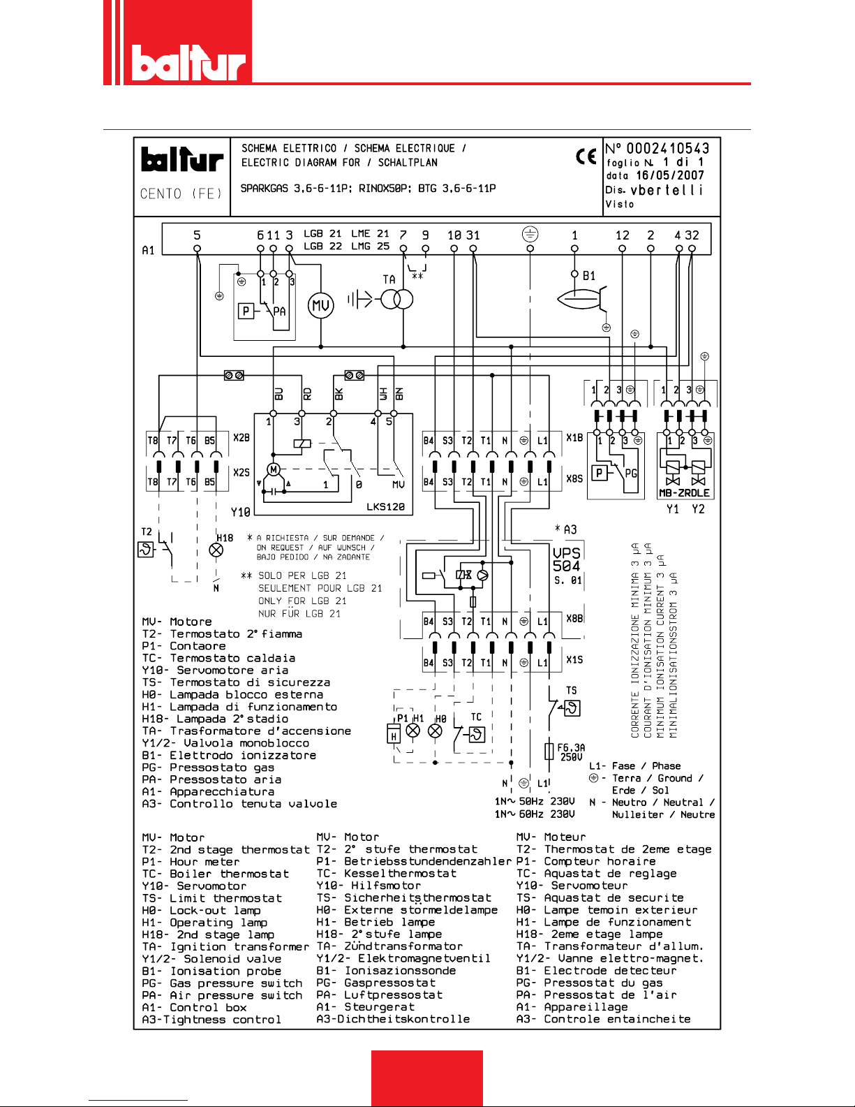
WIRING DIAGRAMS
ENGLISH
29 / 30
0006080763_201611
Page 62

A1 EQUIPMENT
A3 VALVE SEAL CONTROL
B1 PHOTORESISTOR / IONISATION ELECTRODE / UV
PHOTOCELL
H0 EXTERNAL LOCK INDICATOR LIGHT/ AUXILIARY
HEATING ELEMENT OPERATION LAMP
H1 OPERATION INDICATOR LIGHT
H18 “2ND STAGE OPERATION INDICATOR LIGHT“
MV FAN MOTOR
PA AIR PRESSURE SWITCH
P1 “HOUR METER“
PG GAS PRESSURE SWITCH
T2 “2ND STAGE THERMOSTAT“
TA IGNITION TRANSFORMER
TC BOILER THERMOSTAT
TS SAFETY THERMOSTAT
Y1/Y2 1st / 2nd STAGE SOLENOID VALVES
Y10 AIR SERVOMOTOR
Wire series colours
GNYE GREEN / YELLOW
BU BLUE
BN BROWN
BK BLACK
BK* BLACK CONNECTOR WITH OVERPRINT
L1 - L2- L3 Phases
N - Neutral
** Upon request
Ground
ENGLISH
30 / 30
0006080763_201611
Page 63

Page 64

BALTUR S.P.A.
Via Ferrarese, 10
44042 Cento (Fe) - Italy
Tel. +39 051-6843711
Fax. +39 051-6857527/28
www.baltur.it
Il presente catalogo riveste carattere puramente indicativo. La casa, pertanto, si riserva ogni possibilità di modica dei dati tecnici e di quant'altro in esso riportato.
Information contained in this catalogue is not binding. The manufacturer reserves the right to change the technical data and any other data it contains.
 Loading...