

baltur BT 40 DSN 4T, BT 50 DSN 4T, BT 75 DSN 4T, BT 120 DSN 4T, BT 100 DSN 4T Installation, Use And Maintenance Instruction Manual [en, it, es]
...Page 1

BRUCIATORI AD OLIO COMBUSTIBILE BISTADIO
CON CERNIERA
DOUBLE-STAGE DIESEL BURNERS WITH HINGE
QUEMADORES DE ACEITE COMBUSTIBLE DE DOS ETAPAS
CON BISAGRA
ITALIANO
Manuale istruzioni per l'installazione,
l'uso e la manutenzione
Installation, use and maintenance
instruction manuale
Manual de instrucciones para la instala-
ción, el uso y el mantenimiento
IT
EN
ES
BT 40 DSN 4T
BT 50 DSN 4T
BT 75 DSN 4T
BT 100 DSN 4T
BT 120 DSN 4T
BT 180 DSN 4T
BT 250 DSN 4T
BT 300 DSN 4T
BT 350 DSN 4T
ISTRUZIONI ORIGINALI (IT)
ORIGINAL INSTRUCTIONS (IT)
INSTRUCCIONES ORIGINALES (IT)
0006080537_201610
Page 2

Page 3

ITALIANO
DICHIARAZIONE DI CONFORMITÀ
CE0085:
DVGW CERT GmbH, Josef-Wirmer Strasse 1-3-53123 Bonn (D)
Dichiariamo che i nostri bruciatori ad aria sofata di combustibili luquidi, gassosi e misti, domestici e industriali, serie:
BPM...; BGN…; BT…; BTG…; BTL…; TBML...; Comist…; GI…; GI…Mist; Minicomist…; PYR…; RiNOx…; Spark...; Sparkgas...;
TBG...;TBL...; TS…; IBR...; IB...
(Variante: … LX, per basse emissioni NOx)
rispettano i requisiti minimi imposti dalle Direttive Europee:
• 2009/142/CE (D.A.G.)
• 2004/108/CE (C.E.M.)
• 2006/95/CE (D.B.T.)
• 2006/42/CE (D.M.)
e sono conformi alle Norme Europee:
• prEN 676:2012 (gas e misti, lato gas)
• prEN 267:2012 (gasolio e misti, lato gasolio)
• EN 60335-1 (2012-01) + EC (2014-01) (tutti i bruciatori).
Cento, 12 Gennaio 2015
Direttore Ricerca & Sviluppo
Paolo ing. Bolognin
Amministratore Delegato e Direttore Generale
Riccardo dr. Fava
1 / 40
0006080537_201610
Page 4

ITALIANO
AVVERTENZE PER L'USO IN CONDIZIONI
DI SICUREZZA
SCOPO DEL MANUALE
Il manuale si propone di contribuire all'utilizzo sicuro del prodotto
a cui fa riferimento, mediante l'indicazione di quei comportamenti
necessari prevedendo di evitare alterazioni delle caratteristiche
di sicurezza derivanti da eventuali installazioni non corrette, usi
erronei, impropri o irragionevoli.
E’ esclusa qualsiasi responsabilità contrattuale ed extracontrat-
tuale del costruttore per i danni causati da errori nell’installazione
e nell’uso, e comunque da inosservanza delle istruzioni date dal
costruttore stesso.
• Le macchine prodotte hanno una vita minima di 10 anni, se
vengono rispettate le normali condizioni di lavoro ed effettuate
le manutenzioni periodiche indicate dal fabbricante.
• ll libretto di istruzioni costituisce parte integrante ed essenziale
del prodotto e dovrà essere consegnato all’utente.
• L'utente dovrà conservare con cura il libretto per ogni ulteriore
consultazione.
• Prima di iniziare a usare l’apparecchio, leggere attentamen-
te le “Istruzioni per l’uso” riportate nel manuale e quelle
applicate direttamente sul prodotto, al ne di minimizzare i
rischi ed evitare incidenti.
• Prestare attenzione alle AVVERTENZE DI SICUREZZA, non
adottare USI IMPROPRI.
• L'installatore deve valutare i RISCHI RESIDUI che potrebbero
sussistere.
• Per evidenziare alcune parti di testo o per indicare alcune spe-
ciche di rilevante importanza, sono stati adottati alcuni simboli
di cui viene descritto il signicato.
PERICOLO / ATTENZIONE
Il simbolo indica situazione di grave pericolo che, se trascurate, possono mettere seriamente a rischio la salute e la
sicurezza delle persone.
CAUTELA / AVVERTENZE
Il simbolo indica che è necessario adottare comportamenti
adeguati per non mettere a rischio la salute e la sicurezza
delle persone e non provocare danni economici.
IMPORTANTE
Il simbolo indica informazioni tecniche ed operative di particolare importanza da non trascurare.
CONDIZIONI E DURATA DELLO STOCCAGGIO
Gli apparecchi vengono spediti con l'imballaggio del costruttore
e trasportati su gomma, via mare e via ferrovia in conformità con
le norme per il trasporto di merci in vigore per l'effettivo mezzo di
trasporto utilizzato.
Per apparecchi non utilizzati, è necessario conservarli in locali chiusi con la dovuta circolazione d'aria a condizioni standard
(temperatura compresa fra -10° C e + 40° C).
Il preriodo di stoccaggio è di 3 anni.
persone (bambini compresi) le cui capacità siche, sensoriali o
mentali siano ridotte, oppure con mancanza di esperienza o di
conoscenza.
• l'uso dell'apparecchio è consentito a tali persone solo nel caso
in cui possano beneciare, attraverso l'intermediazione di una
persona responsabile, di informazioni relative alla loro sicurezza, di una sorveglianza, di istruzioni riguardanti l'uso dell'appa-
recchio.
• I bambini devono essere sorvegliati per sincerarsi che non giochino con l'apparecchio.
• Questo apparecchio dovrà essere destinato solo all’uso per il
quale é stato espressamente previsto. Ogni altro uso é da considerarsi improprio e quindi pericoloso.
• L’installazione dell’apparecchio deve essere effettuata in ottemperanza alle norme vigenti, secondo le istruzioni del costruttore
a da personale professionalmente qualicato.
• Per personale professionalmente qualicato si intende quello
avente specica e dimostrata competenza tecnica nel settore,
in accordo con la legislazione locale vigente.
• Un’errata installazione può causare danni a persone, animali o
cose, per i quali il costruttore non é responsabile.
• Dopo aver tolto ogni imballaggio assicurarsi dell’integrità del
contenuto. In caso di dubbio non utilizzare l’apparecchio e ri-
volgersi al fornitore. Gli elementi dell’imballaggio non devono
essere lasciati alla portata dei bambini in quanto potenziali fonti
di pericolo.
• La maggior parte dei componenti dell'apparecchio si compo-
ne di materiali che possono essere riutilizzati. L'imballaggio e
l'apparecchio non possono essere smaltiti insieme ai normali
riuti domestici, ma sono soggetti a smaltimento conforme alle
normative vigenti.
• Prima di effettuare qualsiasi operazione di pulizia o manutenzione, disinserire l’apparecchio dalla rete di alimentazione
agendo sull’interruttore dell’impianto e/o attraverso gli appositi
organi di intercettazione.
• Se l’apparecchio dovesse essere venduto o trasferito ad un altro
proprietario o se si dovesse traslocare e lasciare l’apparecchio,
assicurarsi sempre che il libretto accompagni l’apparecchio in
modo che possa essere consultato dal nuovo proprietario e/o
dall’installatore.
• Con apparecchio in funzione non toccare le parti calde normalmente situate in vicinanza della amma e dell’eventuale sistema di preriscaldamento del combustibile. Possono rimanere
calde anche dopo un arresto non prolungato dell'apparecchio.
• Per tutti gli apparecchi con optionals o kit (compresi quelli elettrici) si dovranno utilizzare solo accessori originali.
AVVERTENZE GENERALI
• La data di produzione dell'apparecchio (mese, anno) sono
indicati sulla targa identicazione bruciatore presente
sull'apparecchio.L'apparecchio non è adatto a essere usato da
0006080537_201610
2 / 40
Page 5

ITALIANO
• In caso di guasto e/o di cattivo funzionamento dell’apparecchio,
disattivarlo, astenendosi da qualsiasi tentativo di riparazione o
di intervento diretto. Rivolgersi esclusivamente a personale professionalmente qualicato.
• L’eventuale riparazione dei prodotti dovrà essere effettuata solamente da un centro di assistenza autorizzato da BALTUR o
dal suo distributore locale, utilizzando esclusivamente ricambi
originali.
• Il costruttore e/o il suo distributore locale declinano qualunque
responsabilità per incidenti o danni causati da modiche non
autorizzate sul prodotto o dalla inosservanza delle prescrizioni
contenute nel manuale.
AVVERTENZE DI SICUREZZA PER L’INSTALLAZIONE
• L'apparecchio deve essere installato in un locale idoneo con
una adeguata ventilazione secondo le leggi e norme vigenti.
• La sezione delle griglie di aspirazione dell’aria e le aperture di
aerazione del locale di installazione non devono essere ostruite
o ridotte.
• Il locale di installazione NON deve presentare il rischio di esplo-
sione e/o incendio.
• Prima dell’installazione si consiglia di effettuare una accurata
pulizia interna di tutte le tubazioni dell’impianto di alimentazione
del combustibile.
• Prima di collegare l'apparecchio accertarsi che i dati di targa si-
ano corrispondenti a quelli della rete di alimentazione (elettrica,
gas, gasolio o altro combustibile).
• Accertarsi che il bruciatore sia ssato saldamente al generatore
di calore secondo le indicazioni del costruttore.
• Effettuare gli allacciamenti alle fonti di energia a regola d’arte
come indicato negli schemi esplicativi secondo i requisiti normativi e legislativi in vigore al momento dell’installazione.
• Vericare che l’impianto di smaltimento fumi NON sia ostruito.
• Se si decide di non utilizzare, in via denitiva il bruciatore, si
dovranno far effettuare da personale professionalmente qualicato le seguenti operazioni:
- Disinserire l’alimentazione elettrica staccando il cavo di
alimentazione dell’interruttore generale.
- Chiudere l’alimentazione del combustibile attraverso la
valvola manuale di intercettazione e asportare i volantini di
comando dalla loro sede.
- Rendere innocue quelle parti che potrebbero essere potenziali fonti di pericolo.
• L’impianto di alimentazione del combustibile sia dimensionato
per la portata necessaria al bruciatore e che sia dotato di tutti i
dispositivi di sicurezza e controllo prescritti dalle norme vigenti.
• Prima di avviare il bruciatore e almeno una volta all’anno, far effettuare da personale professionalmente qualicato le seguenti
operazioni:
- Tarare la portata di combustibile del bruciatore secondo la
potenza richiesta dal generatore di calore.
- Eseguire il controllo della combustione regolando la portata
d’aria comburente e/o del combustibile, per ottimizzare il
rendimento di combustione e le emissioni in osservanza alla
legislazione vigente.
- Vericare la funzionalità dei dispositivi di regolazione e di
sicurezza.
- Vericare la corretta funzionalità del condotto di evacuazione dei prodotti della combustione.
- Controllare la tenuta nel tratto interno ed esterno dei tubi di
alimentazione del combustibile.
- Controllare al termine delle regolazioni che tutti i sistemi di
bloccaggio meccanico dei dispositivi di regolazione siano
ben serrati.
- Accertarsi che siano disponibili le istruzioni relative all’uso e
manutenzione del bruciatore.
• In caso di ripetuti arresti in blocco del bruciatore non insistere
con le procedure di riarmo manuale, ma rivolgersi a personale
professionalmente qualicato.
• Allorché si decida di non utilizzare il bruciatore per un certo
periodo, chiudere il rubinetto o i rubinetti di alimentazione del
combustibile.
AVVERTENZE PER L'AVVIAMENTO IL COLLAUDO L'USO E
LA MANUTENZIONE
• L'avviamento, il collaudo e la manutenzione devono essere effettuati esclusivamente da personale professionalmente qualicato, in ottemperanza alle disposizioni vigenti.
• Fissato il bruciatore al generatore di calore, accertarsi durante
il collaudo che la amma generata non fuoriesca da eventuali
fessure.
• Controllare la tenuta dei tubi di alimentazione del combustibile
all'apparecchio.Vericare la portata del combustibile che coincida con la potenza richiesta al bruciatore.
• Tarare la portata di combustibile del bruciatore secondo la po-
tenza richiesta dal generatore di calore.
• La pressione di alimentazione del combustibile deve essere
compresa nei valori riportati nella targhetta, presente sul bru-
ciatore e/o sul manuale
0006080537_201610
3 / 40
Page 6

ITALIANO
Avvertenze particolari per l’uso del gas.
• Vericare che la linea di adduzione e la rampa siano conformi
alle norme e prescrizioni vigenti.
• Vericare che tutte le connessioni gas siano a tenuta.
• Non lasciare l’apparecchio inutilmente inserito quando non è
utilizzato e chiudere sempre il rubinetto del gas.
• In caso di assenza prolungata dell’utente dell’apparecchio chiu-
dere il rubinetto principale di adduzione del gas al bruciatore.
• Avvertendo odore di gas:
- non azionare interruttori elettrici, il telefono e qualsiasi altro
oggetto che possa provocare scintille;
- aprire immediatamente porte e nestre per creare una
corrente d’aria che purichi il locale;
- chiudere i rubinetti del gas;
- richiedere l’intervento di personale professionalmente
qualicato.
• Non ostruire le aperture di aerazione del locale dove é installato
un apparecchio a gas, per evitare situazioni pericolose quali la
formazione di miscele tossiche ed esplosive.
RISCHI RESIDUI
• Nonostante l'accurata progettazione del prodotto, nel rispetto
delle norme cogenti e delle buone regole nell'impiego corretto
possono permanere dei rischi residui. Questi vengono segnalati
sul bruciatore con opportuni Pittogrammi.
ATTENZIONE
Organi meccanici in movimento.
che il lo possa venire a contatto con parti metalliche.
• L’alimentazione elettrica del bruciatore deve prevedere il neutro
a terra. In caso di controllo della corrente di ionizzazione con
neutro non a terra è indispensabile collegare tra il morsetto 2
(neutro) e la terra il circuito RC.
• In caso di assenza prolungata dell’utente dell’apparecchio chiu-
dere il rubinetto principale di adduzione del gas al bruciatore.
• L’uso di un qualsiasi componente che utilizza energia elettrica
comporta l’osservanza di alcune regole fondamentali quali:
- non toccare l’apparecchio con parti del corpo bagnate o
umide e/o a piedi umidi;
- non tirare i cavi elettrici;
- non lasciare esposto l’apparecchio ad agenti atmosferici
(pioggia, sole, ecc.) a meno che non sia espressamente
previsto;
- non permettere che l’apparecchio sia usato da bambini o da
persone inesperte;
- ll cavo di alimentazione dell’apparecchio non deve essere
sostituito dall’utente. In caso di danneggiamento del cavo,
spegnere l’apparecchio. Per la sua sostituzione,rivolgersi
esclusivamente a personale professionalmente qualicato;
- Allorché si decida di non utilizzare l’apparecchio per un
certo periodo é opportuno spegnere l’interruttore elettrico di
alimentazione a tutti i componenti dell’impianto che utilizza-
no energia elettrica (pompe, bruciatore, ecc.).
ATTENZIONE
Materiali a temperature elevate.
ATTENZIONE
Quadro elettrico sotto tensione.
AVVERTENZE SICUREZZA ELETTRICA
• Vericare che l’apparecchio abbia un idoneo impianto di messa
a terra, eseguito secondo le vigenti norme di sicurezza.
• Non utilizzare i tubi del gas come messa a terra di apparecchi
elettrici.
• In caso di dubbi richiedere un controllo accurato dell’impianto
elettrico da parte di personale qualicato, in quanto il costruttore non é responsabile per eventuali danni causati dalla mancanza di messa a terra dell’impianto.Far vericare da personale
professionalmente qualicato che l’impianto elettrico sia adeguato alla potenza massima assorbita dall’apparecchio indicata
in targa.
• Accertarsi che la sezione dei cavi dell’impianto sia idonea alla
potenza assorbita dall’apparecchio.
• Non é consentito l’uso di adattatori, prese multiple e/o prolunghe per l’alimentazione generale dell’apparecchio alla rete elettrica.
• Prevedere un interruttore onnipolare con distanza d’apertura
dei contatti uguale o superiore a 3 mm per l’allacciamento alla
rete elettrica, come previsto dalle normative di sicurezza vigenti
(condizione della categoria di sovratensione III).
• Per l'alimentazione elettrica del bruciatore utilizzare esclusi-
vamente cavi a doppio isolamento, con isolamento esterno di
almeno 1 mm di spessore.
• Sguainare l’isolante esterno del cavo di alimentazione nella
misura strettamente necessaria al collegamento, evitando così
4 / 40
0006080537_201610
Page 7

CARATTERISTICHE TECNICHE
ITALIANO
PORTATA / FLOW RATE MIN Kg/h
MAX Kg/h
POTENZA TERMICA
THERMIC CAPACITY
VISCOSITA’ COMBUSTIBILE
FUEL VISCOSITY
MOTORE VENTOLA / FAN MOTOR kW
MIN kW
MAX kW
vers. normale
normal version
versione Denso
heavy oil version
r.p.m. 2800 2800 2800 2810 2825
TRASFORMATORE / TRANSFORMER VOLT/VOLTIOS
TENSIONE / VOLTAGE TRIFASE
RESISTENZA PRERISCALDATORE
PRE-HEATER RESISTANCES
THREE PHASE
kW
MATERIALI A CORREDO / ACCESSORIES
BT 40
DSN-4T
BT 50
DSN-4T
BT 75
DSN-4T
BT 100
DSN-4T
BT 120
DSN-4T
20 28 40 50 60
40 50 75 100 130
223 312 446 558 669
446 558 837 1116 1451
7°E - 50°C 7°E - 50°C 7°E - 50°C 7°E - 50°C 7°E - 50°C
20°E - 50°C 20°E - 50°C 20°E - 50°C 20°E - 50°C 20°E - 50°C
0,55 1,1 1,1 1,5 2,2
10kV -
30mA
10kV -
30mA
10kV -
30mA
12kV -
30mA
12kV -
30mA
3 N ~ 400V ± 10% 50 Hz
3,2 6 6 7,5 10,5
GUARNIZIONE ISOLANTE /
ISOLATING GASKET
PRIGIONIERI / STUD BOLTS
DADI ESAGONALI / HEXAGONAL NUTS
ROSETTE PIANE / FLAT WASHERS
TUBI FLESSIBILI - FLEXIBLE PIPES
NIPPLI / NIPPLES
FILTRO - FILTER
N° 1 N° 1 N° 1 N° 1 N° 1
N° 4 - M12 N° 4 - M12 N° 4 - M12 N° 4 - M16 N° 4 - M16
N° 4 - M12 N° 4 - M12 N° 4 - M12 N° 4 - M16 N° 4 - M16
N° 4 - Ø12 N° 4 - Ø12 N° 4 - Ø12 N° 4 - Ø16 N° 4 - Ø16
N°1 - 3/4”
N°1 - 1”
N°1 - 3/4”x1” N°1 - 3/4”x1” N°1 - 3/4”x1” N°1 - 3/4”x1” N°1 - 3/4”x1”
N°1 - 1”x1” N°1 - 1”x1” N°1 - 1”x1” N°1 - 1”x1” N°1 - 1”x1”
1” 1” 1” 1” 1”
N°1 - 3/4”
N°1 - 1”
N°1 - 3/4”
N°1 - 1”
N°1 - 3/4”
N°1 - 1”
N°1 - 3/4”
N°1 - 1”
5 / 40
0006080537_201610
Page 8
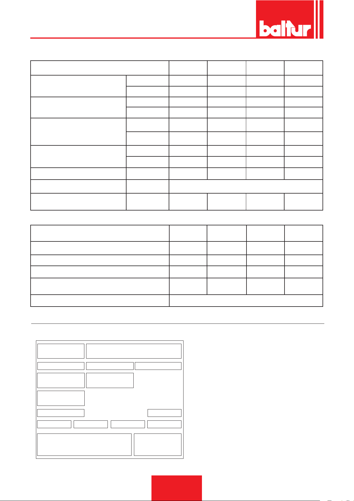
Targa_descr_bru
ITALIANO
MIN Kg/h
PORTATA / FLOW RATE
POTENZA TERMICA
THERMIC CAPACITY
VISCOSITA’ COMBUSTIBILE
FUEL VISCOSITY
MOTORE VENTOLA / FAN MOTOR
TRASFORMATORE / TRANSFORMER / VOLT/VOLTS
TENSIONE / VOLTAGE / TENSÍON
RESISTENZA PRERISCALDATORE
PRE-HEATER RESISTANCES
MAX Kg/h
MIN kW
MAX kW
vers. normale
normal version
versione Denso
heavy oil version
kW
r.p.m. 2870 2870 2870 2900
TRIFASE
THREE PHASE
MATERIALI A CORREDO / ACCESSORIES
GUARNIZIONE ISOLANTE /
ISOLATING GASKET
BT 180
DSN-4T
65 90 110 115
180 280 325 350
725 937 1220 1284
2009 3170 3460 3907
7° E - 50° C 7° E - 50° C 7° E - 50° C 7° E - 50° C
20° E - 50° C 20° E - 50° C 20° E - 50° C 20° E - 50° C
3 7,5 7,5 9
14kV - 30mA 14kV - 30mA 14kV - 30mA 14kV - 30mA
kW
15 18 25,5 28,5
BT 250
DSN-4T
3 N ~ 400V ± 10% 50 Hz
BT 300
DSN-4T
N° 1 N° 1 N° 1 N° 1
BT 350
DSN-4T
PRIGIONIERI / STUD BOLTS N° 4 - M16 N° 4 - M16 N° 4 - M18 N° 4 - M18
DADI ESAGONALI / HEXAGONAL NUTS N° 4 - M16 N° 4 - M16 N° 4 - M18 N° 4 - M18
ROSETTE PIANE / FLAT WASHERS N° 4 - Ø16 N° 4 - Ø16 N° 4 - Ø18 N° 4 - Ø18
TUBI FLESSIBILI - FLEXIBLE PIPES
N°1 - 3/4"
N°1 - 1"1/4
N°1 - 3/4"
N°1 - 1"1/4
N°2 - 1" 1/4 N°2 - 1" 1/4
FILTRO - FILTER 1”1/4
TARGA IDENTIFICAZIONE BRUCIATORE
1 Logo aziendale
2 Ragione sociale azienda
1 2
3 4 5
6 7
8
9
10 13
11
12
14
1615
3 Codice prodotto
4 Modello bruciatore
5 Matricola
6 Potenza combustibili liquidi
7 Potenza combustibili gassosi
8 Pressione combustibili gassosi
9 Viscosità combustibili liquidi
10 Potenza motore ventilatore
11 Tensione di alimentazione
12 Grado di protezione
13 Paese di costruzione e numeri di certicato di omologazione
14 Anno di costruzione
15 16 Codice a barre matricola bruciatore
6 / 40
0006080537_201610
Page 9
DATI REGISTRAZIONE PRIMA ACCENSIONE
Modello: Data: ora:
Tipo di gas
Indice di Wobbe inferiore
Potere calorico inferiore
Portata gas
Portata min gas
Portata max gas
Potenza min gas
potenza max gas
Pressione gas di rete
Pressione gas a valle dello stabilizzatore
CO
CO2
temperatura fumi
temperatura aria
Stm3/h
Stm³/h
Stm³/h
kW
kW
mbar
mbar
ITALIANO
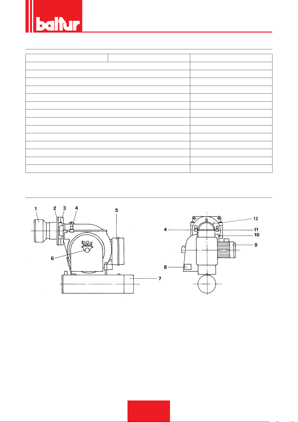
DESCRIZIONE COMPONENTI
1) TESTA DI COMBUSTIONE
2) GUARNIZIONE ISOLANTE
3) CERNIERA
4) ELETTROVALVOLA 1° FIAMMA (normalmente chiusa)
5) QUADRO ELETTRICO
6) POMPA
7) PRERISCALDATORE
8) SERVOMOTORE REGOLAZIONE ARIA
9) MOTORE VENTOLA
10) TRASFORMATORE D'ACCENSIONE
11) ELETTROVALVOLA 2° FIAMMA (normalmente aperta)
12) FOTORESISTENZA
02370281A-tif
7 / 40
0006080537_201610
Page 10
ITALIANO
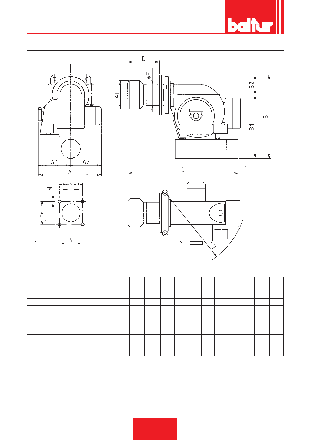
DIMENSIONI DI INGOMBRO
02370281B-tif
MODELLO / MODEL A A1 A2 B B1 B2 C D E F L M N R
Ø Ø Ø
BT 40 DSN 4T/DSN 4T-D 560 300 260 615 465 150 735 145 155 135 230 M 12 170 595
BT 50 DSN 4T/DSN 4T-D 660 340 320 730 580 150 835 145 155 135 230 M 12 170 705
BT 75 DSN 4T/DSN 4T-D 660 340 320 740 580 150 910 220 205 170 230 M 12 220 705
BT 100 DSN 4T/DSN 4T-D 660 340 320 740 580 150 965 265 230 195 240 M 12 240 705
BT 120 DSN 4T/DSN 4T-D 690 320 370 825 665 160 1125 265 230 195 240 M 12 240 865
BT 180 DSN 4T/DSN 4T-D 755 385 370 900 720 180 1210 280 260 225 280 M 16 275 940
BT 250 DSN 4T/DSN 4T-D 945 465 480 1030 850 180 1235 295 260 225 280 M 16 275 940
BT 300 DSN 4T/DSN 4T-D 945 465 490 1170 945 225 1530 420 356 280 360 M 16 370 1135
BT 350 DSN 4T/DSN 4T-D 1085 525 560 1225 1000 225 1530 420 356 280 360 M 16 370 1135
8 / 40
0006080537_201610
Page 11
40 80
160
200
1000
240 280 320 360
kcal/hx10.000
2000 3000
4000
50
100 150
200 250 300 350
5
10
15
20
0
25
30
500
1500
2500 3500
35
120
0002921710
kW
kg/h
mbar
BT 180 DSPN / DSNM-D
BT 250 DSPN / DSNM-D
BT 300 DSPN / DSNM-D
BT 350 DSPN / DSNM-D
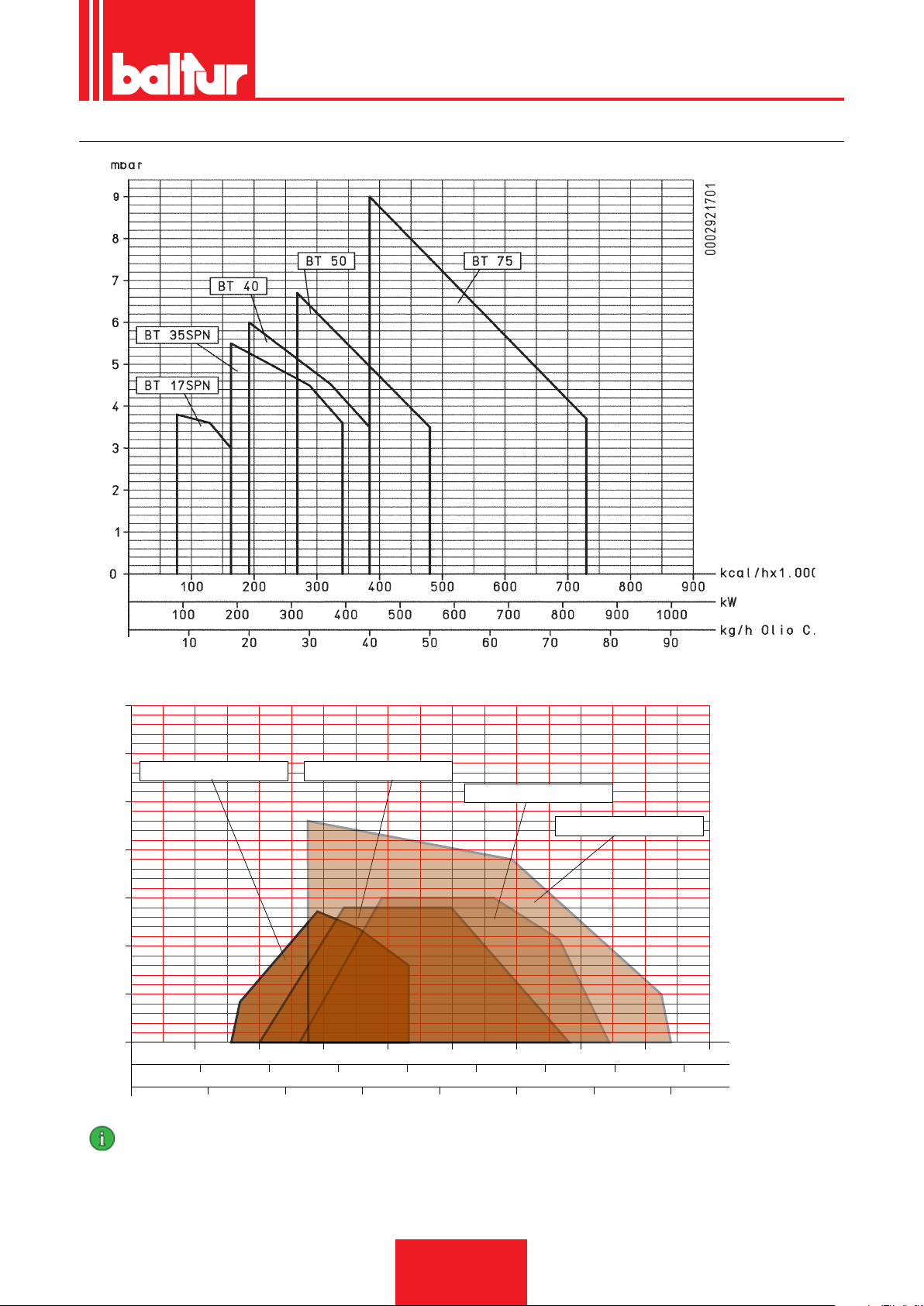
CAMPO DI LAVORO
ITALIANO
IMPORTANTE
I campi di lavoro sono ottenuti su caldaie di prova rispondenti alla norma EN267 e sono orientativi per gli accoppiamenti bruciatore-caldaia. Per il corretto funzionamento del bruciatore le dimensioni della camera di combustione devono essere rispondenti alla
normativa vigente; in caso contrario vanno consultati i costruttori.
Il bruciatore non deve operare al di fuori del campo di lavoro dato.
0006080537_201610
9 / 40
Page 12
ITALIANO
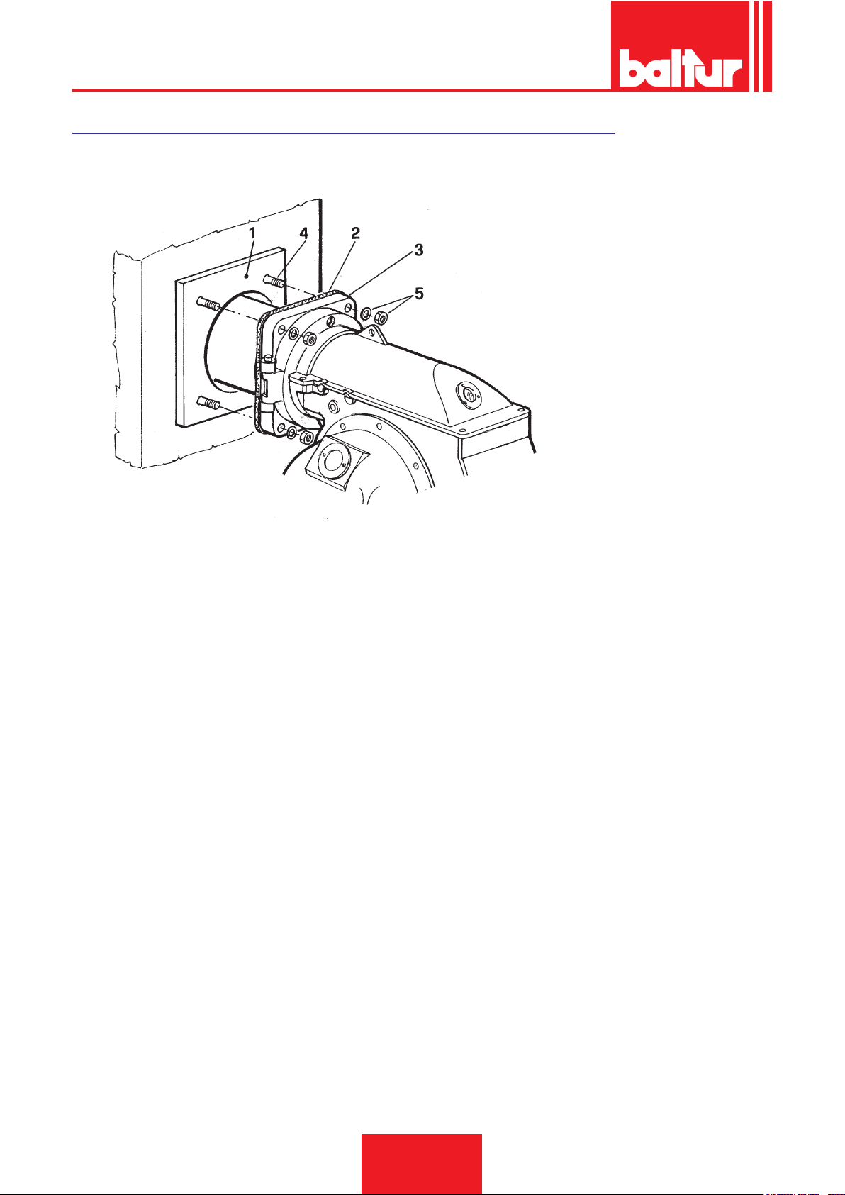
APPLICAZIONE DEL BRUCIATORE ALLA CALDAIA
N° 0002933630
1 - Piastra caldaia
2 - Flangia in materiale isolante
3 - Flange ssaggio bruciatore
4 - Prigioniero
5 - Dado e rondella di bloccaggio
N.B. La profondità di penetrazione della testa, deve essere precisata dal costruttore della caldaia.
Il bruciatore è applicato correttamente se il serbatoio preriscaldatore risulta leggermente inclinato (più alto dal lato uscita combustibile
verso l'ugello) detta inclinazione ha lo scopo di evitare la possibilità di accumulo di gas nel serbatoio stesso. La presenza digas nel
preriscaldatore allunga sensibilmente il tempo necessario per mandare in pressione il combustibile ed è quindi probabile che il bruciatore vada facilmente in blocco. Occorre fare attenzione durante l'applicazione alla caldaia, che il bruciatore non risulti disposto in
modo da annullare questa inclinazione o, peggio ancora, che il preriscaldatore sia inclinato in modo opposto a quello sopra richiesto.
10 / 40
0006080537_201610
Page 13

ITALIANO
PREMESSE PER UNA BUONA INSTALLAZIONE
Prima di procedere all'installazione occorre accertarsi che:
1) Il camino (sezione ed altezza) corrisponda alle disposizioni di Legge.
2) Quando esiste la necessità di realizzare il rivestimento refrattario della camera di combustione (sempre che il
tipo di caldaia lo richieda) è necessario eseguirlo su precise istruzioni del costruttore della caldaia.
3) La linea elettrica di alimentazione del bruciatore va realizzata come da nostro schema ed i collegamenti elettrici
sul bruciatore devono essere predisposti per la tensione della linea di alimentazione.
4) Le tubazioni del combustibile devono essere eseguite come da nostri schemi.
5) L'ugello o gli ugelli applicati sul bruciatore devono essere adeguati alla potenzialità della caldaia, se necessario, sostituirli con
altri. In nessun caso la quantità del combustibile erogata deve essere superiore a quella massima richiesta dalla caldaia e a
quella massima ammessa per il bruciatore. Tenere presente che la testa di combustione è studiata per ugelli con angolo di
spruzzo di 45°. Solo in casi eccezionali potranno essere montati ugelli con angolo di spruzzo diverso, nel qual caso occorrerà
accertarsi che l'ugello con angolo di spruzzo diverso non provochi inconvenienti (distacco di amma, imbrattamento del disco
o della testa di combustione, accensioni violente ecc...).
6) Durante l'asportazione del tappo in plastica di protezione della sede dell'ugello occorre fare attenzione perchè
se il piano di tenuta viene intaccato (basta una leggera rigatura) si provoca gocciolamento di combustibile.
7) Accertarsi che la bocca del bruciatore penetri in camera di combustione come da disposizioni
del costruttore della caldaia.
COLLEGAMENTI ELETTRICI
Tutti i collegamenti devono essere eseguiti con lo elettrico essibile.
Le linee elettriche devono essere convenientemente distanziate dalle parti calde. Assicurarsi che la linea elettrica a cui si vuole
collegare l'apparecchio sia alimentato con valori di tensione e frequenza adatti al bruciatore. Assicurarsi che la linea principale,
il relativo interruttore con fusibili (indispensabile) e l'eventuale limitatore, siano adatti a sopportare la corrente massima assorbita
dal bruciatore. Per i dettagli si vedano gli schemi elettrici specici per ogni singolo bruciatore.
TUBAZIONE DEL COMBUSTIBILE
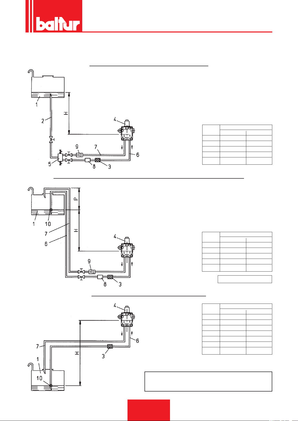
L'esposizione che segue tiene esclusivamente conto di quanto necessario per assicurare un buon funzionamento. L'apparecchio
è dotato di pompa auto - aspirante capace quindi di aspirare direttamente l'olio dalla cisterna anche per il primo riempimento.
Questa affermazione è valida purché sussistano i presupposti necessari, (consultare la tabella relativa alle distanze e ai dislivelli
e il diagramma viscosità - temperatura). Per assicurare un buon funzionamento è preferibile che le tubazioni, di aspirazione
e ritorno, siano eseguite con raccordi saldati evitando le giunzioni a letto che spesso consentono inltrazioni di aria che
disturbano il funzionamento della pompa e quindi del bruciatore. Dove sia indispensabile, eseguire un raccordo smontabile,
si impieghi il sistema a ange saldate con interposta guarnizione resistente al combustibile, che assicura un'ottima tenuta.
Per impianti dove la tubazione necessiti di un diametro relativamente modesto, consigliamo l'impiego del tubo in rame. Nelle
inevitabili giunzioni consigliamo l'impiego di raccordi a "bicono".
Sulle tavole allegate sono riportati gli schemi di principio per diversi tipi di impianti in funzione della posizione della cisterna
rispetto al bruciatore. La tubazione di aspirazione dovrà essere disposta in salita verso il bruciatore, per evitare accumulo
di eventuali bolle di gas. Nel caso in cui vengano installati più bruciatori in un'unica sala caldaia, è indispensabile che ogni
bruciatore abbia un suo tubo di aspirazione. Solo i tubi di ritorno possono conuire in un'unico tubo di sezione adatta per
raggiungere la cisterna. Evitare in ogni caso il collegamento diretto del tubo di ritorno sul tubo di aspirazione. È sempre consi-
gliabile coibentare convenientemente le tubazioni di aspirazione e di ritorno per evitare raffreddamenti funzionalmente dannosi.
I diametri delle tubazioni (da rispettare rigorosamente) sono riportati nelle seguenti tabelle. La depressione massima che la
pompa può sopportare funzionando regolarmente e silenziosamente è di 35 cm.Hg.; se tale valore viene superato, il regolare
funzionamento della pompa non è più garantito.
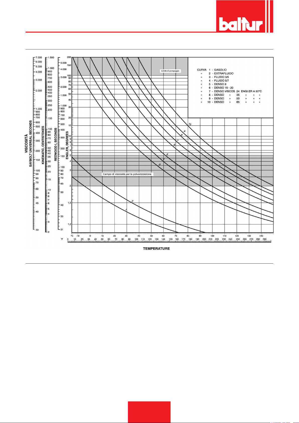
Pressione massima su aspirazione e ritorno = 1 bar. Quando venga impiegato un olio combustibile avente una viscosità
superiore al limite di pompaggio (vedi diagramma) sarà necessario riscaldarlo ad una temperatura tale da permetterne lo
scorrimento nelle tubazioni. Il preriscaldamento in cisterna può essere effettuato con una serpentina di vapore, oppure con una
serpentina di acqua calda. La serpentina deve essere applicata in prossimità del tubo di aspirazione ed in posizione tale da
essere sempre immersa anche con serbatoio al livello minimo. L'entità di questo preriscaldamento si determina consultando
il diagramma viscosità - temperatura. Occorre cioè riscaldare l'olio no a quando la sua viscosità assume un valore al di sotto
della linea che denisce il limite di pompaggio. Un leggero preriscaldamento in cisterna torna comunque sempre vantaggioso
anche se si impiega olio uido (5° E). In particolare se questo preriscaldamento viene realizzato con l'installazione di serpen-
tina a vapore o acqua calda, consente un notevole risparmio di energia elettrica, infatti le resistenze elettriche installate nel
bruciatore devono, in questo caso, elevare la temperatura dell'olio solo del salto termico corrispondente alla differenza tra la
temperatura di arrivo al preriscaldatore e quella a cui viene polverizzato. È bene comunque, ad evitare formazione di gas che
disturba il funzionamento della pompa, che il preriscaldatore in cisterna con olio uido (5° E a 50° C) non superi i 30° C.
11 / 40
0006080537_201610
Page 14
ITALIANO
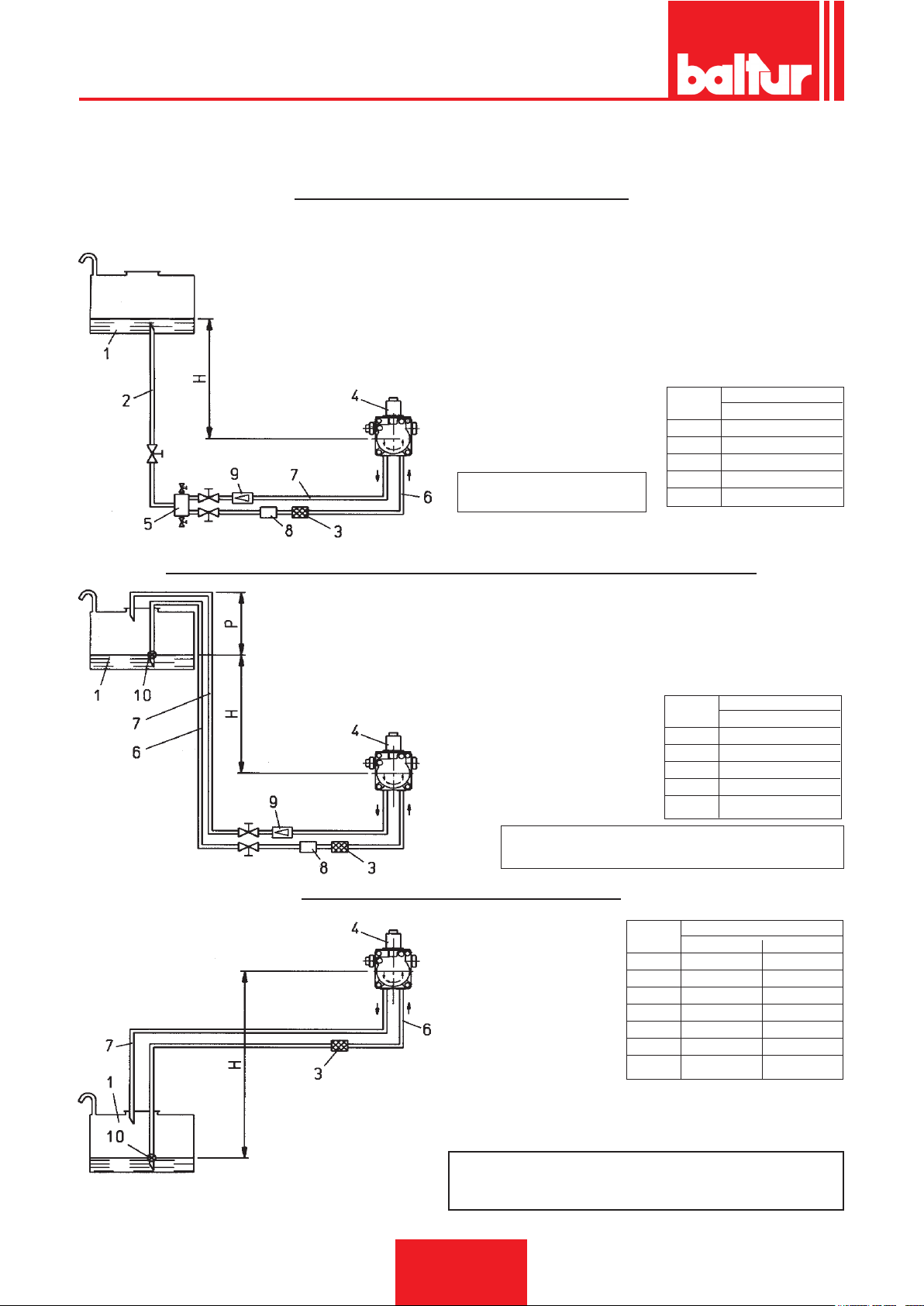
TABELLA TUBAZIONI PER BRUCIATORI MOD. BT 40 - 50 - 75 - 100 DSN - 4T CON COMBUSTIBILE DA
5° E A 50° C (40° E ALLA TEMPERATURA DI POMPAGGIO DI 5° C)
IMPIANTO DI ALIMENTAZIONE PER GRAVITÀ
1 Serbatoio
2 Tubazione di alimentazione
3 Filtro a rete
4 Pompa
5 Degasicatore
6 Tubo di aspirazione
7 Tubo ritorno bruciatore
8 Dispositivo automatico intercettazione a bruciatore fermo
9 Valvola unidirezionale
H L Complessiva
metri metri
ASSE POMPA
Pressione massima su
aspirazione e ritorno = 1 bar
Ø = 1"
1 31
2 35
2,5 35
3 35
IMPIANTO A CADUTA CON ALIMENTAZIONE DALLA SOMMITÀ DEL SERBATOIO
1 Serbatoio
3 Filtro a rete
4 Pompa
6 Tubo di aspirazione
7 Tubo di ritorno
8 Dispositivo automatico intercettazione
a bruciatore fermo
9 Valvola unidirezionale
10 Valvola di fondo
ASSE POMPA
Pressione massima su aspirazione e ritorno = 1 bar
Quota P = 3,5 m. (max.)
IMPIANTO DI ALIMENTAZIONE IN ASPIRAZIONE
1 Serbatoio
ASSE POMPA
3 Filtro a rete
4 Pompa
6 Tubo di aspirazione
7 Tubo di ritorno
10 Valvola di fondo
H L Complessiva
metri metri
Ø = 1"
1 31
2 35
2,5 35
3 35
H L Complessiva metri
metri Ø = 1" Ø 1" 1/4
0,5 22 35
1 17 35
1,5 12 35
2 7 21
2,5 3 8
3 - 3,5 - -
H - Dislivello fra min. livello in serbatoio e asse pompa.
L - Lunghezza totale di ogni tubazione compreso il tratto
verticale. Per ogni gomito o saracinesca detrarre 0,25 m.
12 / 40
0006080537_201610
N.B. Per eventuali organi mancanti nelle tubazioni
attenersi alle norme vigenti.
Page 15
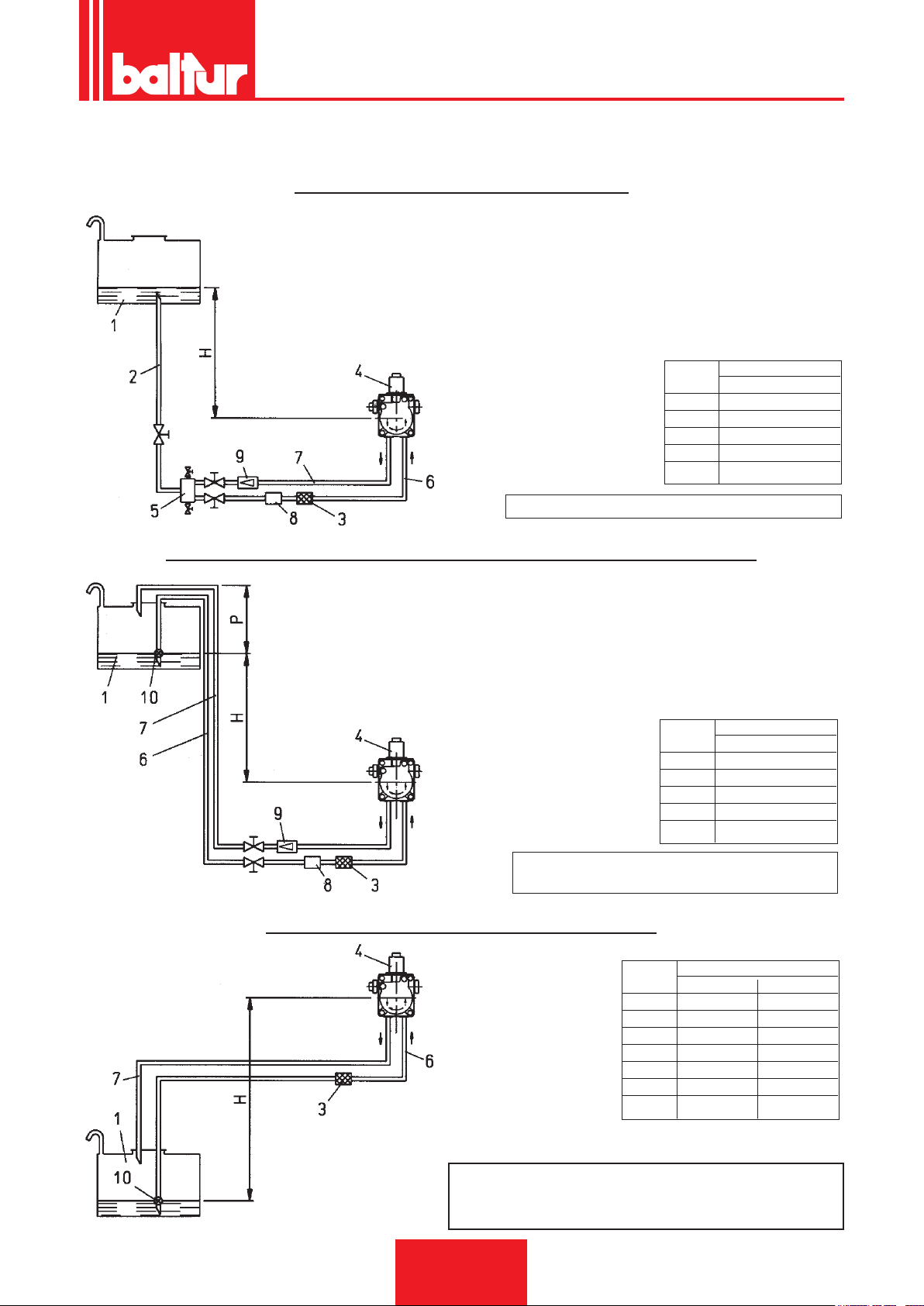
TABELLA TUBAZIONI PER BRUCIATORE MODELLO BT 120 DSN - 4T
CON COMBUSTIBILE DA 5° E A 50° C (40° E ALLA TEMPERATURA DI POMPAGGIO DI 5° C)
IMPIANTO DI ALIMENTAZIONE PER GRAVITÀ
1 Serbatoio
2 Tubazione di alimentazione
3 Filtro a rete
4 Pompa
5 Degasicatore
6 Tubo di aspirazione
7 Tubo ritorno bruciatore
8 Dispositivo automatico intercettazione a bruciatore fermo
9 Valvola unidirezionale
H L Complessiva
metri metri
ASSE POMPA
Pressione massima su aspirazione e ritorno = 1 bar
Ø = 1" 1/4
1 45
1,5 45
2 50
2,5 50
ITALIANO
IMPIANTO A CADUTA CON ALIMENTAZIONE DALLA SOMMITÀ DEL SERBATOIO
1 Serbatoio
3 Filtro a rete
4 Pompa
6 Tubo di aspirazione
7 Tubo di ritorno
8 Dispositivo automatico intercettazione a bruciatore fermo
9 Valvola unidirezionale
10 Valvola di fondo
ASSE POMPA
Pressione massima su aspirazione e ritorno = 1 bar
Quota P = 3,5 m. (max.)
H L Complessiva
metri metri
Ø = 1" 1/4
1 45
1,5 45
2 50
2,5 50
IMPIANTO DI ALIMENTAZIONE IN ASPIRAZIONE
ASSE POMPA
1 Serbatoio
3 Filtro a rete
4 Pompa
6 Tubo di aspirazione
7 Tubo di ritorno
10 Valvola di fondo
H L Complessiva metri
metri Ø = 1" 1/4 Ø 1" 1/2
0,5 35 40
1 30 35
1,5 26 35
2 13 25
2,5 5 10
3 - 3,5 - -
N.B. Per eventuali organi mancanti nelle tubazioni attenersi alle norme vigenti.
H - Dislivello fra min. livello in serbatoio e asse pompa.
L - Lunghezza totale di ogni tubazione compreso il tratto
verticale. Per ogni gomito o saracinesca detrarre 0,25 m.
13 / 40
0006080537_201610
Page 16
ITALIANO
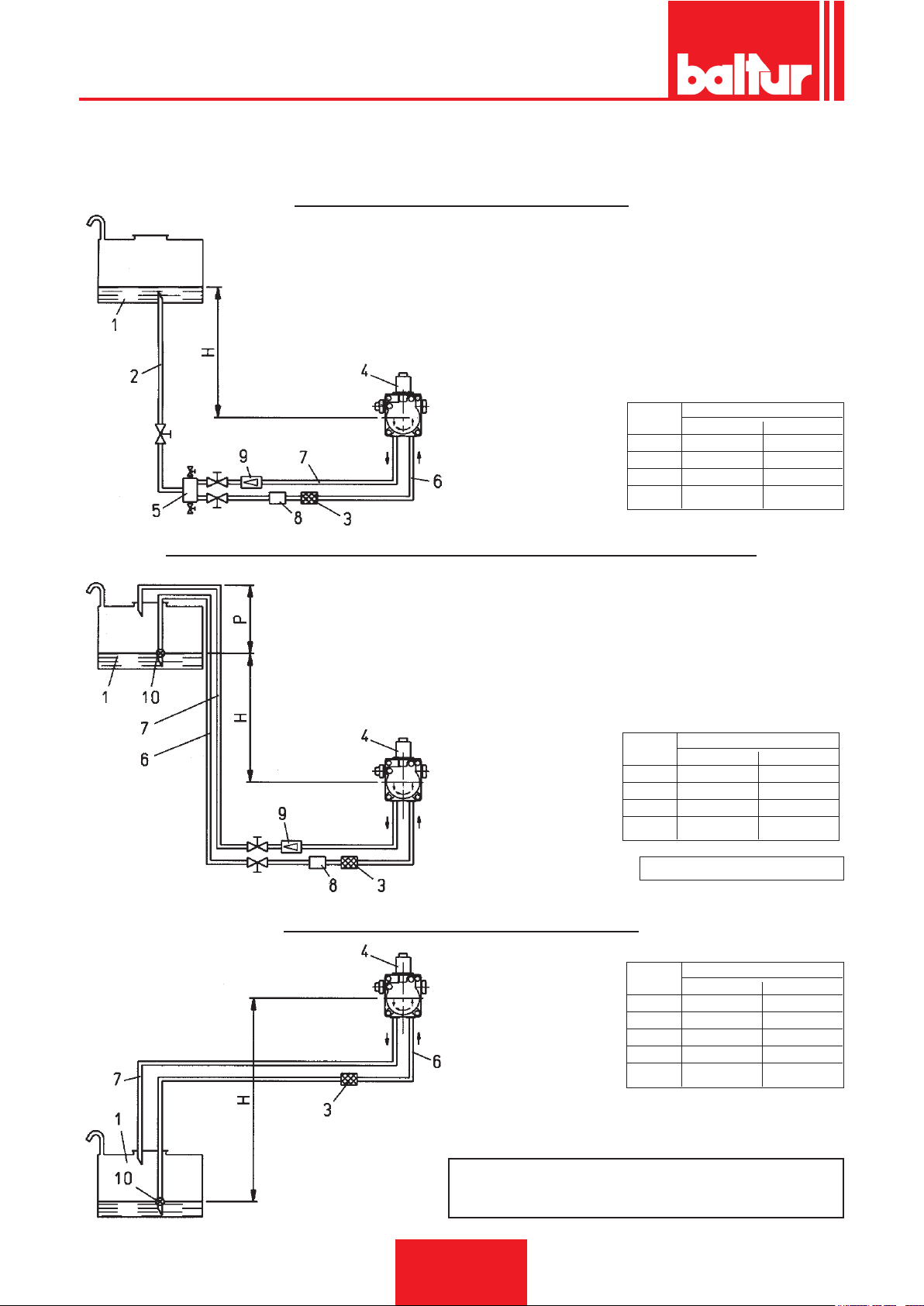
TABELLA TUBAZIONI PER BRUCIATORI MOD. BT 180 DSN - BT 250 DSN
CON COMBUSTIBILE DA 5° E a 50° C (40° E ALLA TEMPERATURA DI POMPAGGIO DI 5° C)
IMPIANTO DI ALIMENTAZIONE PER GRAVITÀ
1 Serbatoio
2 Tubazione di alimentazione
3 Filtro a rete
4 Pompa
5 Degasicatore
6 Tubo di aspirazione
7 Tubo ritorno bruciatore
8 Dispositivo automatico intercettazione a bruciatore fermo
9 Valvola unidirezionale
ASSE POMPA
H L Complessiva metri
metri Ø = 1" 1/2 Øi. 41 mm
1 35 35
1,5 40 40
2 50 50
2,5 50 50
IMPIANTO A CADUTA CON ALIMENTAZIONE DALLA SOMMITÀ DEL SERBATOIO
1 Serbatoio
3 Filtro a rete
4 Pompa
6 Tubo di aspirazione
7 Tubo di ritorno
8 Dispositivo automatico intercettazione a bruciatore fermo
9 Valvola unidirezionale
10 Valvola di fondo
H L Complessiva metri
ASSE POMPA
metri Ø = 1" 1/2 Øi. 41 mm
1 35 35
1,5 40 40
2 50 50
2,5 50 50
IMPIANTO DI ALIMENTAZIONE IN ASPIRAZIONE
1 Serbatoio
ASSE POMPA
0006080537_201610
3 Filtro a rete
4 Pompa
6 Tubo di aspirazione
7 Tubo di ritorno
10 Valvola di fondo
N.B. Per eventuali organi mancanti nelle
tubazioni attenersi alle norme vigenti.
H - Dislivello fra min. livello in serbatoio e asse pompa.
L - Lunghezza totale di ogni tubazione compreso il tratto
verticale. Per ogni gomito o saracinesca detrarre 0,25 m.
14 / 40
Quota P = 3,5 m. (max.)
H L Complessiva metri
metri Ø = 1" 1/2 Øi. 41 mm
0,5 25 25
1 20 20
1,5 15 15
2 10 10
2,5 5 5
Page 17
ITALIANO
TABELLA TUBAZIONI PER BRUCIATORI MOD. BT 300 DSN - BT 350 DSN
CON COMBUSTIBILE DA 5° E a 50° C (40° E ALLA TEMPERATURA DI POMPAGGIO DI 5° C)
IMPIANTO DI ALIMENTAZIONE PER GRAVITÀ
1 Serbatoio
2 Tubazione di alimentazione
3 Filtro a rete
4 Pompa
5 Degasicatore
6 Tubo di aspirazione
7 Tubo ritorno bruciatore
8 Dispositivo automatico intercettazione a bruciatore fermo
9 Valvola unidirezionale
ASSE POMPA
H L Complessiva metri
metri Ø = 1" 1/2 Øi. 41 mm
1 30 30
1,5 35 35
2 40 40
2,5 45 45
3 50 50
IMPIANTO A CADUTA CON ALIMENTAZIONE DALLA SOMMITÀ DEL SERBATOIO
1 Serbatoio
3 Filtro a rete
4 Pompa
6 Tubo di aspirazione
7 Tubo di ritorno
8 Dispositivo automatico intercettazione a bruciatore fermo
9 Valvola unidirezionale
10 Valvola di fondo
H L Complessiva metri
ASSE POMPA
metri Ø = 1" 1/2 Øi. 41 mm
1 30 30
1,5 35 35
2 40 40
2,5 45 45
3 50 50
IMPIANTO DI ALIMENTAZIONE IN ASPIRAZIONE
1 Serbatoio
ASSE POMPA
0006080537_201610
3 Filtro a rete
4 Pompa
6 Tubo di aspirazione
7 Tubo di ritorno
10 Valvola di fondo
N.B. Per eventuali organi mancanti nelle tubazioni attenersi
alle norme vigenti.
H - Dislivello fra min. livello in serbatoio e asse pompa.
L - Lunghezza totale di ogni tubazione compreso il tratto
verticale. Per ogni gomito o saracinesca detrarre 0,25 m.
15 / 40
Quota P = 3,5 m. (max.)
H L Complessiva metri
metri Ø = 1" 1/2 Øi. 41 mm
0,5 25 25
1 20 20
1,5 15 15
2 8 8
2,5 3 3
3 – –
3,5 – –
Page 18
ITALIANO
DIAGRAMMA VISCOSITÀ - TEMPERATURE
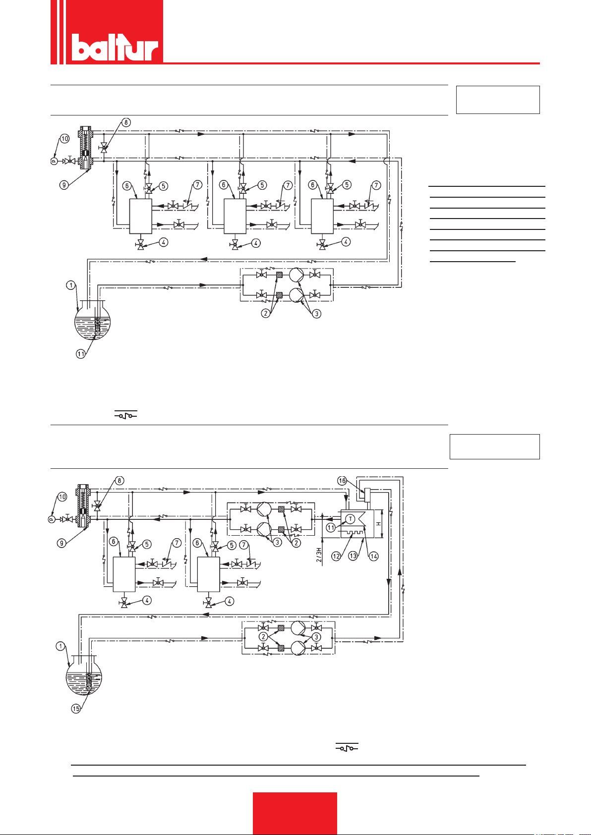
POMPA AUSILIARIA (VEDI BT 8511/6 E BT 8513/7)
In alcuni casi (eccessiva distanza o dislivello oppure viscosità elevata e comunque utilizzando i bruciatori in versione "D" denso) è necessario effettuare l'impianto con un circuito di alimentazione ad "anello", con pompa ausiliaria,
evitando quindi il collegamento diretto della pompa del bruciatore alla cisterna.
In questo caso la pompa ausiliaria può essere messa in funzione alla partenza del bruciatore e fermata all'arresto
dello stesso.
Il collegamento elettrico della pompa ausiliaria si realizza collegando la bobina (230V) che comanda il teleruttore
della pompa stessa, ai morsetti "N" (morsettiera ingresso linea della apparecchiatura) e "L1" (a valle del teleruttore
del motore):
Si raccomanda di eseguire sempre le prescrizioni sotto riportate:
- la pompa ausiliaria deve essere installata il più vicino possibile al liquido da aspirare
- la prevalenza deve essere adeguata all'impianto in questione
- consigliamo una portata almeno pari alla portata della pompa del bruciatore
- le tubazioni di collegamento devono essere dimensionate in funzione della portata della pompa ausiliaria
- evitare assolutamente il collegamento elettrico della pompa ausiliaria direttamente al teleruttore del motore
del bruciatore.
16 / 40
0006080537_201610
Page 19
ITALIANO
SCHEMA IDRAULICO DI PRINCIPIO PER BRUCIATORI A DUE FIAMME O
MODULANTI FUNZIONANTI CON OLIO COMBUSTIBILE (MAX. 15° E A 50 °C)
N.B. I serbatoi di recupero com-
bustibile (diametro 150 mm
altezza 400 mm) devono
essere installati il più vicino possibile al bruciatore
ad una quota superiore di
almeno 0,5 m rispetto alla
pompa dello stesso.
1 - CISTERNA PRINCIPALE
2 - FILTRO
3 - POMPA DI CIRCOLAZIONE
4 - SCARICO ACOUA ED IMPIANTO
5 - SCARICO ARIA-GAS NORMALMENTE CHIUSA
6 - SERBATOIO RECUPERO COMBUSTIBILE E DEGASATORE
7 - VALVOLA DI NON RITORN0
8 - BY PASS (NORMALMENTE CHIUSO)
9 - REGOLATORE DI PRESSIONE REGOLABILE 0,5-2 BAR
10 - MANOMETRO (0-4 BAR)
11 - SERPENTINA DI RISCALDAMENTO OLIO COMBUSTIBILE, A VAPORE OD ACQUA CALDA
CAVO ELETTRICO SCALDANTE (SE NECESSARIO)
N° BT 8511/6
SCHEMA IDRAULICO DI PRINCIPIO PER PIÚ BRUCIATORI A DUE FIAMME O
MODULANTI FUNZIONANTI AD OLIO COMBUSTIBILE DENSO
N° BT 8513/7
( MAX 50 °E A 50 °C) CON RISCALDATORE AUSILIARIO
10 - MANOMETRO (0 - 4 BAR)
1 - CISTERNA PRINCIPALE
2 - FILTRO
3 - POMPA DI CIRCOLAZIONE
4 - SCARICO ACOUA ED IMPIANTO
5 - SCARICO ARIA-GAS NORMALMENTE CHIUSA
6 - SERBATOIO RECUPERO COMBUSTIBILE E DEGASATORE
7 - VALVOLA DI NON RITORN0
6 - BY PASS (NORMALMENTE CHIUSO)
9 - REGOLATORE DI PRESSIONE REGOLABILE 0,5 - 2 BAR
N.B. I serbatoi di recupero combustibile (diametro 150 mm altezza 400 mm) devono essere installati il più vicino
possibile al bruciatore ad una quota superiore di almeno 0,5 m rispetto alla pompa dello stesso.
11 - TERMOMETRO
12 - RESISTENZA
13 - RISCALDATORE AUSILIARIO
14 - SERPENTINO A VAPORE 0 ACOUA CALDA PER
RISCALDAMENTO OLIO
15 - SERPENTINO DI RISCALDAMENTO OLIO
COMBUSTIBILE, A VAPORE OD ACOUA CALDA
16 - BARILOTTO DIAMETRO 100MM ALTEZZA 300MM
CAVO ELETTRICO SCALDANTE (SE NECESSARIO)
17 / 40
0006080537_201610
Page 20

ITALIANO
PRIMO RIEMPIMENTO TUBAZIONE
Dopo aver controllato che i tappi di protezione in plastica posti dentro gli attacchi della pompa siano stati asportati,
si procede come segue:
1) Portare nella posizione "0" l'interruttore posto sul bruciatore.
Questa operazione ha lo scopo di evitare l'inserzione automatica del bruciatore ed in particolare, evita l'in-
serzione delle resistenze che, funzionando con serbatoio vuoto potrebbero bruciare.
2) Assicurarsi, se il bruciatore è trifase, che il motore giri nel senso antiorario, guardando il bruciatore dal lato
pompa. Il senso di rotazione può essere rilevato guardando il senso di rotazione della ventola attraverso la
spia posta sulla parte posteriore della chiocciola. Per mettere in funzione il motore chiudere manualmente il
teleruttore (premendo sulla parte mobile) per qualche istante ed osservare il senso di rotazione della ventola.
Se fosse necessario invertire il senso di rotazione, scambiare di posto due fasi ai morsetti di ingresso della
linea (L1 - L2 - L3).
Nota: Attendere, per stabilire con sicurezza il senso di rotazione, che la ventola giri molto lentamente poichè è
possibile una interpretazione errata del senso di rotazione.
3) Staccare, se già sono stati collegati, i tubi essibili dalla tubazione di aspirazione e da quella di ritorno.
4) Immergere l'estremità del tubo essibile di aspirazione in un recipiente contenente olio lubricante o olio
combustibile (non impiegare prodotti con bassa viscosità come gasolio, petrolio, benzina, kerosene ecc...).
5) Premere ora sulla parte mobile del teleruttore del motore per mettere in funzione il motore stesso e quindi la
pompa. Attendere che la pompa abbia aspirato una quantità di lubricante pari a 1 o 2 bicchieri, quindi fermare.
Questa operazione ha lo scopo di evitare il funzionamento della pompa a secco e di aumentare il potere
aspirante.
N.B. Le pompe che lavorano a 2800 giri non devono assolutamente lavorare a secco, perchè si blocchereb-
bero (grippaggio) in brevissimo tempo.
6) Collegare ora il essibile al tubo di aspirazione ed aprire tutte le eventuali saracinesche poste su questo tubo
nonchè ogni altro eventuale organo di intercettazione del combustibile.
7) Premere ora nuovamente sulla parte mobile del teleruttore del motore per mettere in funzione la pompa che aspirerà il combustibile dalla cisterna. Quando si vedrà uscire il combustibile dal tubo di ritorno (non ancora collegato),
fermare.
Nota: Se la tubazione è lunga, può essere necessario sfogare l'aria dall'apposito tappo, se la pompa non ne è
provvista asportare il tappo dell'attacco manometro. In questo caso quando si vede uscire il combustibile
dal foro di attacco del manometro occorre interrompere l'operazione e rimettere il tappo. Riprendere
quindi l'operazione di caricamento no a quando si è riempito il serbatoio (il serbatoio preriscaldatore è
pieno quando si vede uscire il combustibile dal tubo essibile di ritorno non ancora collegato).
8) Collegare il tubo essibile di ritorno alla tubazione ed aprire le saracinesche poste su questo tubo. Il bruciatore
è così pronto per essere acceso.
DESCRIZIONE DEL FUNZIONAMENTO
NOTA: I bruciatori in versione "D" (denso) sono forniti con resistenza ausiliaria per la pompa, per il gruppo polverizzatore e per le due elettrovalvole, ed il ltro di linea è preriscaldato.
Chiudendo l'interruttore sul bruciatore si inserisce il teleruttore delle resistenze (se il relativo termostato lo con-
sente). La tensione giunge al teleruttore delle resistenze attraverso il contatto del termostato di regolazione. Le
resistenze così inserite, riscaldano l'olio combustibile nel serbatoio preriscaldatore. Quando la temperatura dell'olio
ha raggiunto il valore sufciente, si chiude il termostato di minima, alla chiusura del quale, se gli altri termostati
(regolazione e sicurezza) lo consentono, la corrente arriva all'apparecchiatura che inserisce, secondo il programma
prestabilito, i dispositivi componenti il bruciatore. L'inserzione del trasformatore d'accensione avviene contemporaneamente a quella del motore del bruciatore (utilizzando l'apparecchiatura OR 3/B), con apparecchiatura
LAL 1.25 il trasformatore viene inserito alcuni secondi dopo. Il motore mette in rotazione la ventola, che effettua
la preventilazione con aria nella camera di combustione, e contemporaneamente la pompa, che determina una
circolazione dell'olio caldo nei condotti espellendo, attraverso il ritorno, l'olio freddo ed eventuale gas. Questa fase
di "prelavaggio" e "preventilazione" ha termine con la chiusura dell'elettrovalvola n° 7 (aperta nella posizione di
riposo) che interrompe il libero scarico dell'olio verso la cisterna. Alla chiusura dell'elettrovalvola fa seguito l'aumento
della pressione nei condotti di mandata.
18 / 40
0006080537_201610
Page 21

ITALIANO
NOTA: Il ltro a rete del preriscaldatore incorpora una valvola a molla (antigas) che si apre consentendo il usso
del combustibile solo quando si raggiunge una pressione di circa 2 ÷ 2,5 bar. Questa valvola ha lo scopo di
tenere sotto leggera pressione il preriscaldatore anche con bruciatore spento per ridurre, e possibilmente
evitare, la formazione di gas con olio caldo e bruciatore spento. La perdita di pressione dovuta a questa
valvola "antigas" è di circa 2 ÷ 2,5 bar e, pertanto, occorre regolare la pressione di polverizzazione (pres-
sione pompa) ad un valore maggiore per compensare la perdita di pressione. In pratica si deve regolare la
pressione della pompa a 27 bar. Quando tale pressione raggiunge il valore di 16 bar, si apre il dispositivo di
chiusura ugello n° 4 che si trova nel gruppo polverizzatore consentendo all'olio di raggiungere l'ugello della
1a amma e, da questo uscire in camera di combustione nemente polverizzato. La pressione si stabilizza
al valore di circa 27 bar perché a questo valore è tarato il regolatore di pressione della pompa. Appena
l'olio polverizzato esce dall'ugello viene incendiato dalla scarica agli elettrodi che è già presente. Durante
l'accensione della 1a amma la serranda dell'aria è mantenuta dal servomotore nella posizione registrata,
in funzione della quantità di combustibile bruciato. Se compare regolarmente la amma, si supera la posizione di blocco si disinserisce il trasformatore d'accensione e si inserisce l'elettrovalvola di 2a amma n°
8 (chiusa a riposo). L'apertura della valvola di 2a amma, consente al combustibile, alla pressione di 25
bar, di raggiungere il dispositivo di chiusura ugello 2° stadio n° 4/1. La pressione di 27 - 2 = 25 bar, agisce
sul dispositivo di chiusura ugello del 2° stadio che, no ad una pressione di 16 bar impedisce l'afusso del
combustibile al secondo ugello. Questo dispositivo viene così aperto dalla pressione stessa, ed entra in
funzione anche il secondo ugello. La pressione di 25 bar agisce ora sui due ugelli. Per rilevare l'effettiva
pressione al gruppo polverizzatore e quindi agli ugelli, consigliamo di collegare il manometro nell'apposito
attacco del ltro serbatoio (vedi dis. 0002932230).
NOTA: Da quanto sopra esposto risulta evidente che la scelta degli ugelli, in funzione della portata totale
(2 ugelli in funzione) desiderata, deve essere effettuata tenendo conto dei valori di portata corrispondenti
alla pressione di lavoro di 25 bar. Occorre però tenere presente che, quando il bruciatore lavora con la sola
prima amma inserita, l'erogazione del combustibile è quella corrispondente ad un solo ugello in funzione
alla pressione di 25 bar. È ovviamente possibile variare entro ampi limiti il rapporto tra la prima e la seconda
amma, sostituendo gli ugelli. Tenere comunque presente che, per avere un buon funzionamento, l'erogazione di combustibile con la prima amma, non dovrebbe essere inferiore alla portata minima (rilevabile
sulla targhetta) per il modello specico. Una portata inferiore potrebbe rendere difcile l'accensione, e la
combustione con la sola prima amma potrebbe non essere buona.
NOTA:Alcuni modelli di bruciatori utilizzano tre ugelli (vedi dis. n° 0002900564) in tal caso gli ugelli della seconda
amma sono due ed entrambi sottoposti alla pressione di 25 bar.
Dal momento della comparsa della amma in camera di combustione, il bruciatore è comandato e controllato dalla
fotoresistenza e dai termostati. Quando la temperatura o pressione raggiunge il valore a cui è tarato il termostato
o pressostato di esercizio, l'intervento dello stesso determina l'arresto del bruciatore.
L'apparecchio ritorna in funzione automaticamente quando il valore della temperatura o pressione si è abbassata
della quantità necessaria. Se per un qualsiasi motivo, durante il funzionamento viene a mancare la amma, inter-
viene immediatamente (un secondo) la fotoresistenza che, interrompendo l'alimentazione del relè omonimo, ne
determina l'apertura e, quindi, la disinserzione della elettrovalvola n° 7 del lavaggio che, aprendosi scarica rapidamente la pressione esistente e lo spruzzo di olio polverizzato viene intercettato dalla chiusura automatica dei dispositivi di chiusura ugello del gruppo polverizzatore appena la pressione va al di sotto del valore a cui sono regolati.
In questo caso (se utilizzata l'apparecchiatura mod. OR 3/B) si ripete automaticamente la fase di accensione e, se
la prima amma si riaccende normalmente, il funzionamento del bruciatore riprende pure normalmente, in caso
contrario (amma irregolare o completamente assente) l'apparecchio si porta automaticamente in blocco. Utilizzando l'apparecchiatura modello LAL 1.25 in caso di mancanza di amma il bruciatore si porta in blocco senza
tentare una seconda accensione. Se il programma viene interrotto (mancanza di tensione, intervento manuale,
intervento di termostato ecc...) durante la fase di prelavaggio il programmatore ritorna nella sua posizione iniziale
e ripete tutta la fase di accensione del bruciatore.
CARATTERISTICHE APPARECCHIATURA
Modello Apparecchiatura e Tempo di sicurezza Tempo di preventilazione Post-accensione Tempo fra 1a e
Bruciatore relativo programmatore in secondi in secondi in secondi 2
in secondi
BT 40 DSN - 4T
BT 55 DSN - 4T OR 3/B 5 30 5 5
BT 75 DSN - 4T
BT 100 DSN - 4T
BT 120 DSN - 4T
BT 180 DSN - 4T
BT 250 DSN - 4T LAL 1.25 5 22,5 15 7,5
BT 300 DSN - 4T
BT 350 DSN - 4T
Relè ciclico
0006080537_201610
19 / 40
a
amma
Page 22

ITALIANO
ACCENSIONE E REGOLAZIONE
Prima dell'accensione è necessario assicurarsi che:
a) I collegamenti con la linea di alimentazione, con i termostati o pressostati, siano eseguiti esattamente secondo
lo schema elettrico dell'apparecchiatura.
b) Ci sia combustibile in cisterna e acqua nella caldaia.
c) Tutte le saracinesche poste sulla tubazione di aspirazione e ritorno dell'olio combustibile siano aperte e così
pure ogni altro organo di intercettazione del combustibile.
d) Lo scarico dei prodotti di combustione possa avvenire liberamente (serrande della caldaia e del camino
aperte).
e) Accertarsi che la testa del bruciatore penetri in camera di combustione come da disposizioni del costruttore della
caldaia. Per poter rispettare questa disposizione il bruciatore è provvisto di angia di attacco della caldaia,
scorrevole rispetto alla testa di combustione.
f) Gli ugelli applicati sul bruciatore siano adatti alla potenzialità della caldaia e, se necessario, sostituirli con altri.
In nessun caso la quantità di combustibile erogata deve essere superiore a quella massima richiesta dalla
caldaia e a quella massima ammessa per il bruciatore. Tenere presente che la testa di combustione è studiata
per ugelli con angolo di spruzzo di 45°.
Nota: Per avere una buona accensione ed una buona combustione con la sola prima amma, occorre che
l'erogazione di combustibile non sia sensibilmente inferiore alla portata minima (rilevabile dalla targhetta)
per il bruciatore specico.
PER L'ACCENSIONE SI PROCEDE COME SEGUE:
Nota: Il bruciatore, è provvisto di interruttore per passare manualmente dal 1° al 2° stadio.
a
1) Aprire l'interruttore 1° e 2° stadio per impedire l'inserzione della 2
amma.
2) Aprire leggermente la serranda dell'aria, per consentire il usso d'aria che si presume necessaria per il funzionamento del bruciatore con la 1a amma agendo sulla camma che limita la corsa del servomotore per la 1a
amma (vedi BT 8653/1 o BT 8711/1), regolare in una posizione intermedia il dispositivo di regolazione dell'aria
sulla testa di combustione (vedasi più avanti, al capitolo "Regolazione dell'aria sulla testa di combustione").
3) Inserire l'interruttore generale e quello di marcia arresto sul bruciatore. Con questa nuova manovra si inseriscono
subito le resistenze che riscaldano l'olio combustibile e, contemporanea mente, si ha l'accensione della relativa
spia gialla posta sul bruciatore.
4) Il termostato di minima si chiude quando il combustibile, contenuto nel preriscaldatore, raggiunge la tempera-
tura a cui lo stesso è regolato. La chiusura del termostato di minima determina, se gli altri termostati di caldaia
sono chiusi, l'inserzione dell'apparecchiatura che inserisce, secondo il programma prestabilito, i dispositivi
componenti il bruciatore. L'apparecchio si accende, così come descritto nel capitolo "Descrizione del Funziona-
mento".
5) Quando il bruciatore è in funzione alla 1a amma, si provvede a regolare, operando come descritto al n° 2,
l'aria nella quantità necessaria per assicurare una buona combustione. È preferibile che la quantità di aria
per la 1a amma sia leggermente scarsa in modo da assicurare un'accensione perfetta anche nei casi più
impegnativi.
6) Dopo aver regolato l'aria per la 1a amma si ferma il bruciatore, togliendo corrente dall'interruttore generale,
si collegano tra di loro i morsetti della morsettiera del termostato della 2a amma e si posiziona l'interruttore
1° e 2° stadio in posizione 2° stadio.
7) Si agisce sulla camma che limita la corsa del servomotore di comando serranda aria della 2a amma, regolan-
dola della quantità che si presume necessaria per il combustibile da bruciare (vedi BT 8653/1 o BT 8711/1).
8) Si inserisce ora nuovamente l'apparecchio che si accende e passa automaticamente, secondo il programma
stabilito dal programmatore, alla 2a amma.
9) Con l'apparecchio così in funzione con la 2a amma, si provvede a regolare, (operando sulla camma di cui al
punto 7), l'aria nella quantità necessaria per assicurare una buona combustione. Il controllo della combustione
dovrebbe essere effettuato con gli appositi strumenti. Se non si dispongono degli strumenti adatti ci si basa
sul colore della amma. Consigliamo di regolare in modo da ottenere una amma morbida, di colore arancio
chiaro evitando amm rossa con presenza di fumo, come pure amma bianca con esagerato eccesso di aria.
20 / 40
0006080537_201610
Page 23

ITALIANO
Il regolatore dell'aria deve essere in posizione tale da consentire una percentuale di anidride carbonica (CO2) nei
fumi, variabile da un minimo del 10% ad un massimo del 13% con un numero di fumo non superiore a quello previsto
dalla norma (scala Bacharach). Se non si dispongono degli strumenti adatti ci si basa sul colore della amma.
Consigliamo di regolare in modo da ottenere una amma morbida, di colore arancio chiaro evitando amma
rossa con presenza di fumo, come pure amma bianca con esagerato eccesso di aria. (Vedi anche capitolo
"Regolazione dell'aria sulla testa di combustione".
10) La regolazione dei termostati del preriscaldatore, termostato di minima e termostato di regolazione (max) viene
effettuata dal costruttore su valori che possono essere inaccettabili per il caso singolo, occorre quindi, all'atto
del collaudo, vericare che detti valori non comportino anomalie (cattiva combustione, presenza di fumo,
formazione di gas nel preriscaldatore, ecc...). Se è necessario, variare questi valori in più o in meno, tenendo
presente che il termostato di regolazione deve comunque trovarsi ad una temperatura di circa 15° più alta di
quella cui è regolato il termostato di minima. Il termostato di minima deve chiudersi alla temperatura minima
indispensabile afnchè il combustibile arrivi all'ugello con una viscosità non superiore a 2° E. Questa condizione
è indispensabile per avere una buona polverizzazione. (Vedi a titolo indicativo il diagramma viscosità - temperatura
relativo al tipo di olio impiegato).
REGOLAZIONE DELL'ARIA SULLA TESTA DI COMBUSTIONE
La testa di combustione è dotata di dispositivo di regolazione, in modo da chiudere (spostare in avanti) o aprire
(spostare indietro) il passaggio dell'aria tra il disco e la testa. Si riesce così ad ottenere, chiudendo il passaggio,
un'elevata pressione a monte del disco anche per le portate basse. L'elevata velocità e turbolenza dell'aria consente una migliore penetrazione della stessa nel combustibile e quindi, un'ottima miscela e stabilità di amma.
Può essere indispensabile avere un'elevata pressione d'aria a monte del disco, per evitare pulsazioni di amma,
questa condizione è praticamente indispensabile quando il bruciatore lavora su focolare pressurizzato e/o ad alto
carico termico. Da quanto sopra esposto risulta evidente che il dispositivo che chiude l'aria sulla testa di combu-
stione deve essere portato in una posizione tale da ottenere sempre dietro al disco un valore decisamente elevato
della pressione dell'aria. Si consiglia di regolare in modo da realizzare una chiusura dell'aria sulla testa, tale da
richiedere una sensibile apertura della serranda aria che regola il usso all'aspirazione del ventilatore bruciatore, ovviamente questa condizione si deve vericare quando il bruciatore lavora alla massima erogazione desiderata.
In pratica si deve iniziare la regolazione con il dispositivo che chiude l'aria sulla testa di combustione in una posizione intermedia accendendo il bruciatore per una regolazione orientativa come esposto precedentemente.
Quando si è raggiunta l'erogazione massima desiderata si provvede a correggere la posizione del dispositivo che
chiude l'aria sulla testa di combustione, spostando in avanti o indietro, in modo da avere un usso d'aria adeguato
all'erogazione, con serranda di regolazione dell'aria in aspirazione sensibilmente aperta.
Riducendo il passaggio dell'aria sulla testa di combustione, occorre evitarne la chiusura completa. Provvedere alla
perfetta centratura rispetto al disco. Precisiamo che se manca la perfetta centratura rispetto al disco si potrebbe
vericare cattiva combustione ed eccessivo riscaldamento della testa con conseguente rapido deterioramento.
La verica si effettua guardando dalla spia posta sulla parte posteriore del bruciatore, successivamente, stringere
a fondo le viti che bloccano la posizione del dispositivo di regolazione dell'aria sulla testa di combustione.
N.B. Controllare che l'accensione avvenga regolarmente perché, nel caso in cui si sia spostato il regolatore in
avanti, può capitare che la velocità dell'aria in uscita sia talmente elevata da rendere difcoltosa l'accensione. Se si verica questo caso, occorre spostare più indietro, per gradi, il regolatore no a raggiungere
una posizione in cui l'accensione avviene regolarmente ed accettare questa posizione come denitiva.
Ricordiamo ancora che è preferibile, per la 1
per avere un'accensione sicura anche nei casi più impegnativi.
a
amma, limitare la quantità di aria allo stretto indispensabile
REGOLAZIONE DISTANZA TRA DISCO E UGELLO
I bruciatori sono provvisti di un dispositivo che consente di variare la distanza tra il disco e l'ugello.
La distanza tra il disco e l'ugello, regolata dalla casa, deve essere ridotta solo se si rileva che il cono di combustibile polverizzato in uscita dall'ugello bagna il disco con conseguente imbrattamento.
21 / 40
0006080537_201610
Page 24

ITALIANO
CONTROLLI
Acceso il bruciatore occorre controllare i dispositivi di sicurezza (fotoresistenza, blocco, termostati).
1) La fotoresistenza è il dispositivo di controllo amma, e deve quindi essere in grado di intervenire se, durante
il funzionamento, la amma si spegne (questo controllo deve essere effettuato dopo almeno 1 minuto dall'av-
venuta accensione).
2) Il bruciatore deve essere in grado di portarsi in blocco e restarci quando, in fase di accensione e nel tempo prestabilito dall'apparecchiatura di comando, non compare regolarmente la amma. Il blocco comporta l'interruzione
immediata del combustibile, l'arresto del motore e quindi del bruciatore, e l'accensione della corrispondente
segnalazione luminosa di blocco. Per controllare l'efcienza della fotoresistenza e del blocco, operare come
segue:
a) mettere in funzione il bruciatore
b) dopo almeno un minuto dall'avvenuta accensione estrarre la fotoresistenza, slandola dalla sua sede,
simulando la mancanza di amma con l'oscuramento della fotoresistenza (chiudere con uno straccio la
nestra ricavata nel supporto della fotoresistenza). La amma del bruciatore deve spegnersi (utilizzando
l'apparecchiatura mod. LAL 1.25 il bruciatore si porta in blocco).
c) Se si utilizza l'apparecchiatura mod. OR 3/B continuando a mantenere la fotoresistenza al buio, il
bruciatore si riaccende ma, la fotoresistenza non vede la luce e, nel tempo determinato dal programma
della apparecchiatura, si porta in blocco.
L'apparecchiatura si può sbloccare solo con intervento manuale pigiando l'apposito pulsante.
3) Per controllare l'efcienza dei termostati, si fa funzionare il bruciatore no a quando la acqua in caldaia raggiunge la
temperatura di almeno 50° C, e quindi, si agisce sulla manopola di comando del termostato nel senso di abbassare
la temperatura no ad avvertire lo scatto di apertura e contemporaneamente l'arresto del bruciatore. Lo scatto del
termostato deve avvenire con uno scarto massimo di 5 + 10° C rispetto al termostato di controllo (termometro di
caldaia); in caso contrario modicare la taratura della scala del termostato facendola corrispondere a quella del
termometro.
USO DEL BRUCIATORE
Il bruciatore è a funzionamento completamente automatico; chiudendo l'interruttore generale e quello del quadro
di comando il bruciatore viene inserito. Il funzionamento del bruciatore viene comandato dai dispositivi di comando e controllo descritto nel capitolo "Descrizione del funzionamento". La posizione di "blocco" è una posizione di
sicurezza in cui il bruciatore si porta, automaticamente, quando qualche particolare del bruciatore o dell'impianto
è inefciente; è quindi opportuno accertarsi, prima di inserire nuovamente il bruciatore "sbloccandolo", che in
centrale termica non esistano anormalità. Nella posizione di blocco il bruciatore può restare senza limiti di tempo.
I bloccaggi possono essere causati anche da irregolarità transitorie (un poco di acqua nel combustibile, aria nella
tubazione ecc...); in questi casi, se sbloccato, il bruciatore si avvia regolarmente. Quando invece i bloccaggi si
ripetono successivamente (3 - 4 volte) non si deve insistere e, dopo aver controllato che ci sia combustibile in
cisterna, richiedere l'intervento del Servizio Assistenza, competente per zona, che rimedierà all'anomalia. Per
sbloccare l'apparecchiatura premere l'apposito pulsante.
MANUTENZIONE
Il bruciatore non richiede alcuna particolare manutenzione; è bene però, almeno alla ne della stagione di riscaldamento, eseguire le seguenti operazioni:
1) smontare e lavare accuratamente con solventi (benzina, trielina, petrolio) i ltri, lo spruzzatore, il disco turbolatore e gli elettrodi d'accensione. Evitare, per la pulizia dell'ugello, l'uso di strumenti metallici (usare legno o
plastica).
2) Pulizia della fotoresistenza.
3) Far pulire la caldaia e, se necessario, anche il camino.
22 / 40
0006080537_201610
Page 25

ITALIANO
N.B. L'ugello o gli ugelli devono essere sostituiti almeno ogni due stagioni di riscaldamento.
Può però essere necessario effettuare la suddetta operazione con maggior frequenza.
DESCRIZIONE DEL FUNZIONAMENTO DEI BRUCIATORI A DUE FIAMME
Il bruciatore a due amme si accende sempre con portata ridotta (1a amma) di combustibile e di aria e, successivamente, dopo alcuni secondi, passa al funzionamento a pieno regime (2a amma) di combustibile e di aria.
L'inserzione della 2a amma è subordinata al consenso dell'apparecchiatura e a quello del dispositivo di comando
(pressostato e termostato). Quando l'apparecchio è in funzione a pieno regime, resta in questa posizione no
al raggiungimento del valore di pressione o temperatura a cui è regolato il dispositivo di comando (pressostato
o termostato). Il dispositivo di comando scatta, disinserendo la seconda amma, (combustibile ed aria) quando si
raggiunge il valore a cui lo stesso è regolato. Il bruciatore resta così in funzione con la sola prima amma.
La sola prima amma non è, normalmente, sufciente per mantenere la pressione o temperatura al valore desiderato, e quindi la stessa diminuirà no a raggiungere il valore a cui il dispositivo di comando della seconda
amma (pressostato o termostato) inserisce nuovamente la portata totale di aria e combustibile. Il bruciatore viene
arrestato completamente quando, con la sola prima amma inserita, la pressione o temperatura raggiunge il valore
di intervento del dispositivo di esercizio (pressostato otermostato). Automaticamente l'apparecchio si riaccende
quando la pressione o temperatura diminuisce al di sotto del valore a cui il pressostato o termostato è regolato.
N.B. È normalmente sconsigliabile collegare per funzionamento a due amme effettive, un bruciatore che lavori
su una caldaia per produzione d'acqua ad uso riscaldamento. In questo caso il bruciatore lavora (a volte
anche lunghi periodi di tempo) ad una sola amma, la caldaia risulta insufciente caricata; di conseguenza,
i prodotti di combustione escono ad una temperatura eccessivamente bassa (inferiore ai 180° C) dando
luogo a presenza di fuliggine allo sbocco del camino. Quando la caldaia è insufcientemente caricata è
molto probabile la formazione di condensa acida e di fuliggine in caldaia con conseguente rapido intasamento
e corrosione della stessa. Quando il bruciatore a due amme è installato su una caldaia per produzione di
acqua ad uso riscaldamento, deve essere collegato in modo da lavorare a regime con entrambe le amme
arrestandosi completamente, senza passaggio alla prima amma, quando la temperatura prestabilita viene
raggiunta. Per ottenere questo particolare funzionamento non si installa il termostato della seconda amma e
fra i rispettivi morsetti dell'apparecchiatura si realizza un collegamento diretto (ponte). Il tal modo si utilizza
solo la capacità del bruciatore di accendersi a portata ridotta per realizzare un'accensione dolce, condizione
indispensabile per le caldaie con camera di combustione in pressione (pressurizzata), ma molto utile anche
nelle caldaie normali (camera di combustione in depressione). Il comando (inserzione o arresto) del bruciatore
è subordinato ai soliti termostati di esercizio o sicurezza.
23 / 40
0006080537_201610
Page 26

ITALIANO
ISTRUZIONI PER LA DETERMINAZIONE DELLE CAUSE DI IRREGOLARETÀ NEL
FUNZIONAMENTO DEI BRUCIATORI E LORO ELIMINAZIONE
NATURA DELL'IRREGOLARITÁ
L'apparecchio va in blocco con la
amma.
(Lampada rossa accesa)
Il guasto è circoscritto al dispositivo
di controllo amma.
L'apparecchio va in blocco spruzzando combustibile senza il vericarsi della amma. (Lampada rossa
accesa)
Il guasto è circoscritto al dispositivo di accensione, ammesso che il
combustibile sia in buone condizioni
(non inquinato da acqua o altro) e
sufficientemente riscaldato se si
tratta di olio combustibile (nafta) e
sufcientemente polverizzato.
L'apparecchio va in blocco spruzzando combustibile senza il vericarsi della amma (lampada rossa
accesa).
CAUSA POSSIBILE
1) Fotoresistenza interrotta o sporca di
fumo
2) Tiraggio insufciente
3) Circuito della fotoresistenza interrotto
4) Disco o bocca sporchi
1) Interruzione nel circuito di accensione
2) I cavetti del trasformatore di accensione
scaricano a massa
3) I cavetti del trasformatore non sono ben
collegati
4) Trasformatore di accensione
interrotto
5) Le punte degli elettrodi non sono alla
giusta distanza
6) Gli elettrodi scaricano a massa perchè
sporchi o per isolante incrinato; control-
lare anche sotto i morsetti di ssaggio
degli isolanti
1) La pressione della pompa non è regolare
2) Presenza di acqua nel combustibile
3) Preriscaldamento dell'olio
combustibile insufciente
4) Eccesso di aria di combustione
5) Passaggi dell'aria tra disco e
bocca eccessivamente chiuso
6) Ugello logoro o sporco
RIMEDIO
1) Pulirla o sostituirla
2) Controllare tutti i passaggi dei fumi nella
caldaia o nel camino
3) Sostituire l'apparecchiatura
4) Pulirli
1) Vericare tutto il percorso
2) Sostituirli
3) Bloccarli
4) Sostituirlo
5) Riportarle nella posizione prescritta
6) Pulirli, se necessario, sostituirli
1) Ritararla
2) Scaricarla dal serbatoio
preriscaldatore e dal ltro sgrossatore attraver-
so gli appositi tappi. Scaricarla, se necessario,
anche dalla cisterna servendosi di una pompa
adatta. (Non usare mai per questo lavoro la
pompa del bruciatore).
3) Aumentarlo
4) Ridurre l'aria di combustione
5) Correggere la posizione del dispositivo
di regolazione della testa di combustione
6) Sostituirlo o pulirlo
L'apparecchio va in blocco senza
spruzzare combustibile (lampada
rossa accesa).
1) Manca una fase
2) Motore elettrico insufciente
3) Olio combustibile che non arriva alla
pompa
4) Manca olio combustibile in cisterna
5) La saracinesca del tubo di aspirazione è
chiusa
6) Ugello otturato
7) Motore (trifase) che gira in senso
contrario a quello indicato dalla freccia
8) Valvola di fondo che perde o è bloccata
9) Pompa difettosa
10)Formazione nel preriscaldatore di vapore
acqueo o di gas che ne ritardano il riempimento (in questo caso il manometro
raggiungerà lentamente la pressione di
esercizio prevista (troppo tardi rispetto al
tempo massimo concesso dal programmatore)
11) Filtro del serbatoio preriscaldatore
intasato
12) Elettrovalvola inefciente
13) Valvola del gruppo polverizzatore che
non si apre
14)Tensione troppo bassa
1) Controllare la linea di alimentazione
2) Ripararlo o sostituirlo
3) Controllare la tubazione di aspirazione
4) Effettuare il riempimento
5) Aprirla
6) Smontarlo e pulirlo in ogni sua parte
7) Invertire una fase nell'interruttore di
alimentazione
8) Smontarla e pulirla
9) Sostituirla
10)Allentare di alcuni giri i tappi del
serbatoio preriscaldatore e scaricare l'eventuale acqua presente. Se non si rilevasse
fuoriuscita di acqua bensì di combustibile è
da ritenersi che i gas prodottisi all'interno del
preriscaldatore provengano da evaporazione
del combustibile; procedere quindi abbassando la temperatura del termostato regolatore al
di sotto dei 100 °C. Controllare anche l'inclina-
zione del serbatoio come esposto al capitolo
"Applicazione del bruciatore alla caldaia".
11)Smontarlo e pulirlo
12)Controllarla ed eventualmente sostituirla
13)Dopo aver controllato che la pressione
del combustibile sia quella prevista, sostituire il
gruppo polverizzatore
14)Provvedere ad interpellare la società
fornitrice dell'energia elettrica
24 / 40
0006080537_201610
Page 27

ITALIANO
NATURA DELL'IRREGOLARITÁ
Pompa del bruciatore rumorosa
Olio combustibile che si scalda troppo
lentamente o non si scalda
Bruciatore che non parte al raggiungimento della temperatura minima di pre-
riscaldamento dell'olio combustibile
Bruciatore che non parte
CAUSA POSSIBILE
1) Olio combustibile troppo viscoso in
cisterna
2) Tubazioni di diametro troppo piccolo
3) Inltrazione di aria nei tubi
4) Filtro sgrossatore sporco
5) Distanza eccessiva fra cisterna e
bruciatore oppure molte perdite accidentali
(curve, gomiti, strozzature, ecc.)
6) Tubi essibili deteriorati
7) Olio combustibile troppo viscoso in
qualche tratto della tubazione di aspira-
zione
1) Tensione di linea troppo bassa
2) Una o più resistenze bruciate
3) Collegamenti elettrici
4) Potenza complessiva delle resistenze
inferiore al fabbisogno in rapporto alla portata
dell'ugello
1) Termostati (caldaia o ambiente) o
pressostati, aperti
2) Fotoresistenza in corto circuito
1) Manca la tensione per interruttore
generale aperto o interruttore di massima del
contatore scattato o mancanza di tensione
in linea
2) La linea dei termostati non è stata eseguita
secondo schema o qualche termostato è
rimasto aperto
3) Guasto interno all'apparecchiatura
RIMEDIO
1) Preriscaldarlo in cisterna o sostituirlo con
tipo più uido
2) Sostituirle attenendosi alle relative
istruzioni
3) Vericare ed eliminare tale inltrazione
4) Smontarlo e lavarlo
5) Retticare l'intero sviluppo del tubo di
aspirazione riducendo così la distanza
6) Sostituirli
7) Provvedere ad isolare adeguatamente
tutta la tubazione
1) Intervenire presso l'Ente fornitrice
l'energia elettrica
2) Sostituirla
3) Controllare
4) Diminuire la portata compatibilmente con
la richiesta di calore dell'impianto
1) Alzarne il valore o attendere che si
chiudano per diminuzione naturale della
temperatura o pressione
2) Sostituirla
1) Chiudere gli interruttori o attendere il
ritorno della tensione
2) Controllare collegamenti e termostati
3) Sostituirla
Fiamma difettosa con presenza di
faville
Fiamma non ben conformata con fumo
e fuliggine
1) Olio combustibile troppo freddo
2) Pressione di polverizzazione troppo bassa
3) Eccesso di aria comburente
4) Ugello di portata insufciente perchè
sporco o logoro
5) Acqua nel combustibile
1) Insufcienza di aria comburente
2) Ugello inefciente perchè sporco o logoro
3) Camera di combustione di forma non
adatta o troppo piccola
4) Ugello di portata insufciente rispetto al
volume della camera di combustione
5) Temperatura dell'olio combustibile troppo
bassa
6) Rivestimento refrattario non adatto o
eccessivo
7) Condotti della caldaia o camino ostruiti
8) Pressione di polverizzazione bassa
1) Aumentare la temperatura tramite il
termostato regolatore del preriscaldatore
2) Ripristinarla al valore previsto
3) Diminuire l'aria di combustione
4) Pulirlo o sostituirlo
5) Scaricarla dal serbatoio preriscaldatore e
dal ltro sgrossatore attraverso gli appositi
tappi. Scaricarla, se necessario, anche
dalla cisterna servendosi di una pompa
adatta. (non usare mai per questo lavoro
la pompa del bruciatore)
1) Aumentare l'aria di combustione
2) Pulirlo o sostituirlo
3) Modicarla o diminuire la portata
dell'ugello in rapporto alla camera di com-
bustione o sostituire la caldaia
4) Aumentare la portata dell'ugello
sostituendolo
5) Aumentarla
6) Modicarlo o alleggerirlo attenendosi alle
istruzioni del costruttore della caldaia
7) Provvedere alla loro pulizia
8) Provvedere a riportarla al valore prescritto
25 / 40
0006080537_201610
Page 28

ITALIANO
NATURA DELL'IRREGOLARITÁ
Fiamma difettora, pulsante o sfug-
gente dalla bocca di combustione
Corrosioni interne nella caldaia
Fuliggine allo sbocco del camino
CAUSA POSSIBILE
1) Tiraggio esuberante (solo in caso di
esistenza di un aspiratore al camino)
2) Temperatura di preriscaldamento non
adatta alla quantità dell0lio combustibile
impiegato
3) Ugello inefciente perchè sporco o logoro
4) Presenza di acqua nell'olio combustibile
5) Disco sporco
6) Eccesso di aria di combustione
7) Passaggio dell'aria tra disco e bocca
eccessivamente chiuso
1) Temperatura di esercizio della caldaia
troppo bassa (inferiore al punto di rugiada)
2) Alta percentuale di zolfo nell'olio
combustibile
3) Temperatura dei fumi troppo bassa (al di
sotto dei 180 °C)
1) Eccessivo raffreddamento (al di sotto dei
180°C) dei fumi prima dello sbocco, per camino esterno, non sufcientemente coibentato,
oppure per inltrazioni di aria fredda
RIMEDIO
1) Adeguare la velocità dell'aspiratore
modicando i diametri delle pulegge
2) Aumentarla o diminuirla
3) Pulirlo o sostituirlo
4) Scaricarla dal serbatoio preriscaldatore e
dal ltro sgrossatore attraverso gli appositi
tappi. Scaricarla, se necessario, anche dalla
cisterna servendosi di una pompa adatta.
(Non usare mai per questo lavoro la pompa
del bruciatore)
5) Pulirlo
6) Ridurre l'aria di combustione
7) Correggere la posizione del dispositivo di
regolazione della testa di combustione
1) Aumentare la temperatura di esercizio
2) Cambiare qualità di olio combustibile
3) Aumentare la portata dell'ugello
sostituendolo
1) Migliorare l'isolamento ed eliminare ogni
apertura che possa consentire l'ingresso di
aria fredda
26 / 40
0006080537_201610
Page 29
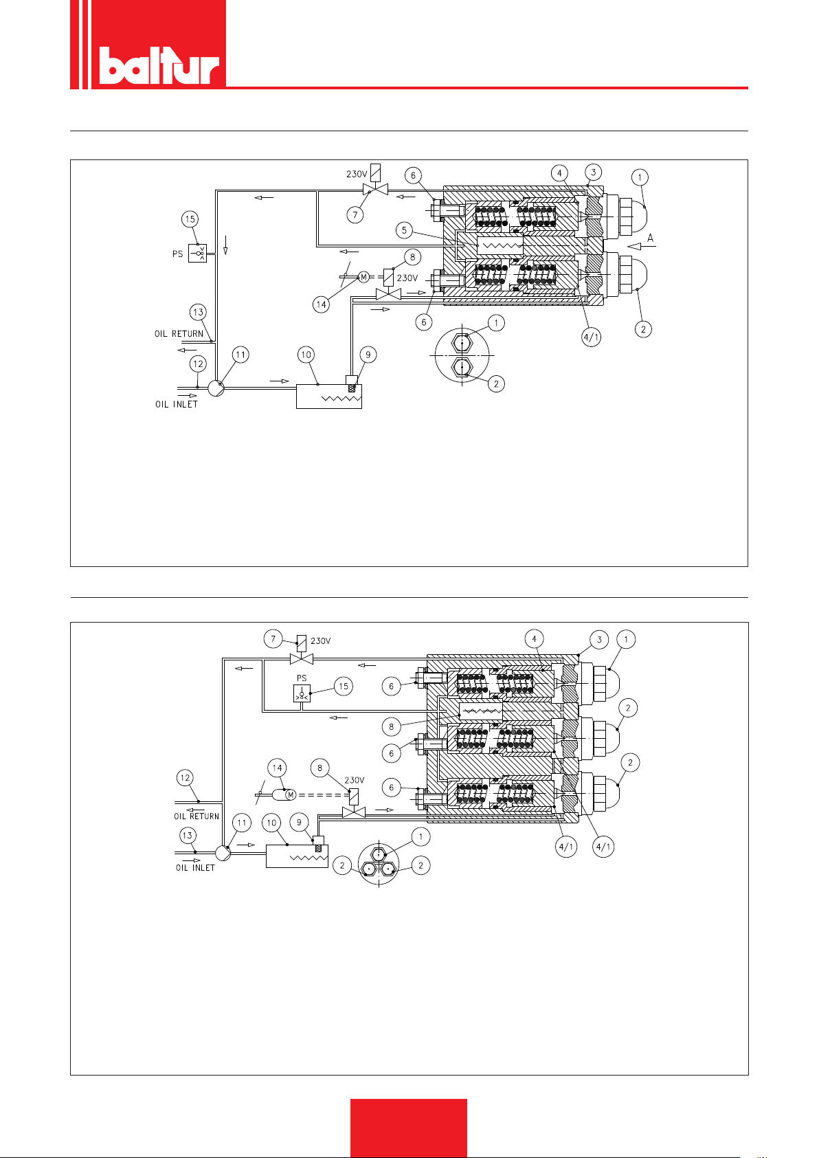
0002904640
0002900565
SCHEMA DI PRINCIPIO CIRCUITO IDRAULICO BT 40 - 55 - 75 - 100 - 120 - 180 DSN 4T
VISTA FRONTALE
ITALIANO
1 ugello 1° stadio
2 ugello 2° stadio
3 gruppo polverizzatore porta ugelli con dispositivo
chiusura regolabile
4 dispositivo chiusura ugello 1° stadio (tarato 16 bar)
4/1 dispositivo chiusura ugello 2° stadio (tarato 16 bar)
5 resistenza W 20 (solo versione "D" per elevata viscosità
del combustibile)
6 vite di regolazione dispositivo di chiusura
7 valvola normalmente aperta 1° stadio
8 valvola normalmente chiusa 2° stadio
9 filtro autopulente (300 µ)
10 preriscaldatore
11 pompa (tarata 27 bar)
12 ritorno
13 aspirazione
14 servomotore regolazione aria
15 pressostato massima Olio C. 0÷16 bar (tarato a 5 bar).
SCHEMA DI PRINCIPIO CIRCUITO IDRAULICO BT 250 - 300 - 350 DSN 4T
VISTA FRONTALE
1 ugello 1° stadio
2 ugello 2° stadio
3 gruppo polverizzatore porta ugelli con dispositivo
chiusura regolabile
4 dispositivo chiusura ugello 1° stadio (tarato 16 bar)
4/1 dispositivo chiusura ugello 2° stadio (tarato 16 bar)
5 resistenza W 80 (solo versione denso)
6 vite di regolazione dispositivo di chiusura
7 valvola normalmente aperta 1° stadio
27 / 40
0006080537_201610
8 valvola normalmente chiusa 2° stadio
9 filtro con valvola antigas (∆p 2 ÷ 2,5 bar)
10 preriscaldatore
11 pompa (tarata 27 bar)
12 ritorno
13 aspirazione
14 servomotore regolazione aria
15 pressostato massima Olio C. 0÷16 bar (tarato a 5 bar)
Page 30
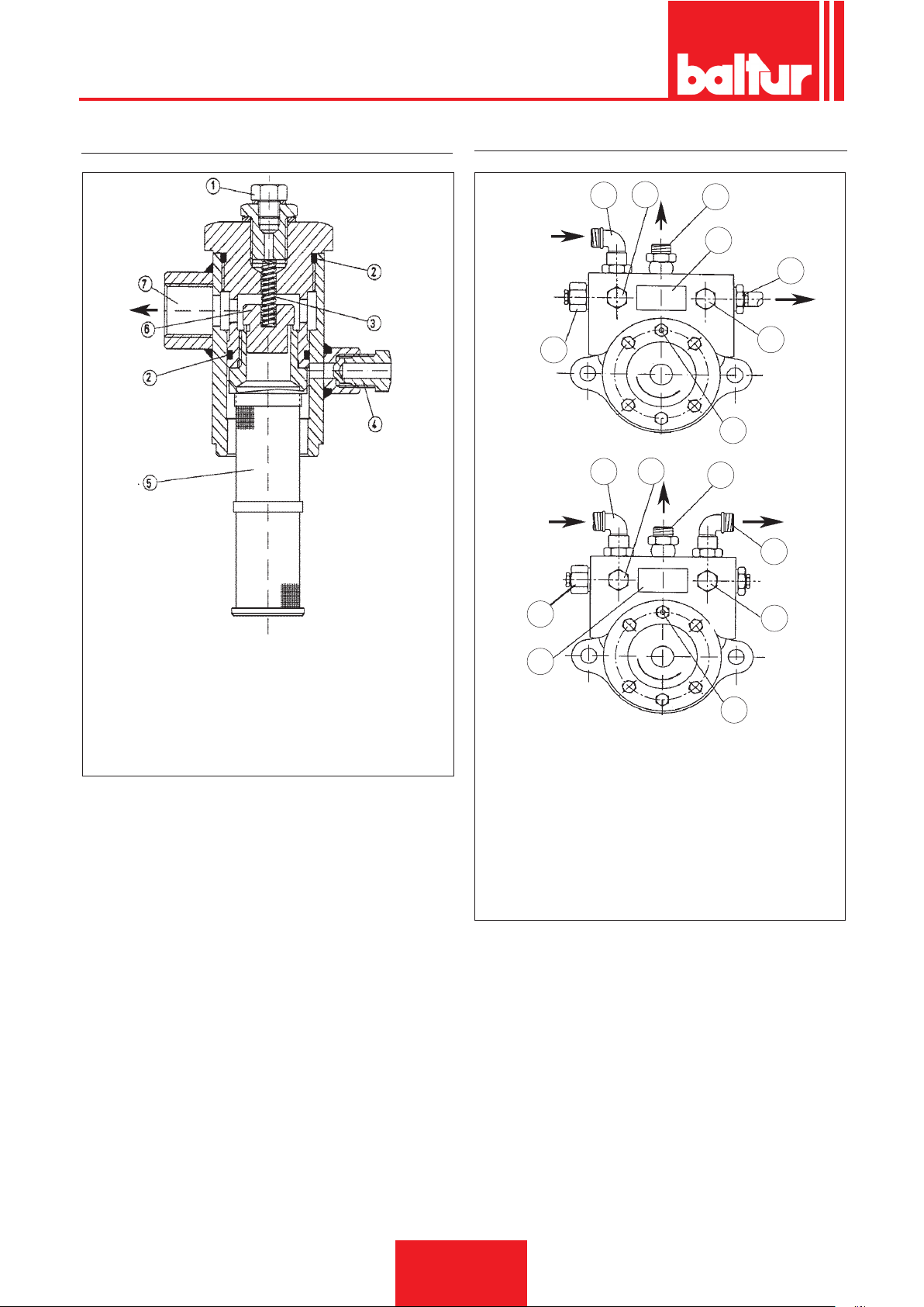
ITALIANO
FILTRO SERBATOIO CON VALVOLA ANTIGAS
POMPA BALTUR MOD. BT...
1
0002900570
8
1
2
3
4
0002900580
5
6
7
2
3
5
1) Attacco manometro Rp 1/2"
2) Guarnizione O-Ring
3) Molla di chiusura valvola (∆p = 2 ÷ 3 bar)
4) Tappo sfiato aria
5) Filtro a rete
6) Otturatore valvola antigas
7) Uscita combustibile al gruppo polverizzatore
8
4
N° 0002932230
1 Aspirazione
2 Attacco vuotometro ¼”
3 Ritorno
4 Targa pompa
5 Mandata ugello
6 Attacco manometro ¼”
7 Sede elemento riscaldante
8 Regolazione pressione pompa (20 ÷ 22 bar)
6
7
28 / 40
0006080537_201610
Page 31

TABELLA PORTATA UGELLI
ITALIANO
Ugello
G.P.H. Portata all’uscita dell’ugello G.P.H.
0,40 1,27 1,36 1,44 1,52 1,59 1,67 1,73 1,80 1,86 1,92 1,98 2,04 2,10 2,15 2,20 0,40
0,50 1,59 1,70 1,80 1,90 1,99 2,08 2,17 2,25 2,33 2,40 2,48 2,55 2,62 2,69 2,75 0,50
0,60 1,91 2,04 2,16 2,28 2,39 2,50 2,60 2,70 2,79 2,88 2,97 3,06 3,14 3,22 3,30 0,60
0,65 2,07 2,21 2,34 2,47 2,59 2,71 2,82 2,92 3,03 3,12 3,22 3,31 3,41 3,49 3,58 0,65
0,75 2,38 2,55 2,70 2,85 2,99 3,12 3,25 3,37 3,49 3,61 3,72 3,82 3,93 4,03 4,13 0,75
0,85 2,70 2,89 3,06 3,23 3,39 3,54 3,68 3,82 3,96 4,09 4,21 4,33 4,45 4,57 4,68 0,85
1,00 3,18 3,40 3,61 3,80 3,99 4,16 4,33 4,50 4,65 4,81 4,96 5,10 5,24 5,37 5,51 1,00
1,10 3,50 3,74 3,97 4,18 4,38 4,58 4,77 4,95 5,12 5,29 5,45 5,61 5,76 5,91 6,06 1,10
1,20 3,82 4,08 4,33 4,56 4,78 5,00 5,20 5,40 5,59 5,77 5,95 6,12 6,29 6,45 6,61 1,20
1,25 3,97 4,25 4,50 4,75 5,00 5,20 5,40 5,60 5,80 6,00 6,20 6,35 6,55 6,70 6,85 1,25
1,35 4,29 4,59 4,87 5,13 5,38 5,62 5,85 6,07 6,28 6,49 6,69 6,88 7,07 7,26 7,44 1,35
1,50 4,77 5,10 5,41 5,70 5,90 6,24 6,50 6,75 6,98 7,21 7,43 7,65 7,86 8,06 8,26 1,50
1,65 5,25 5,61 5,95 6,27 6,58 6,87 7,15 7,42 7,68 7,93 8,18 8,41 8,64 8,87 9,09 1,65
1,75 5,56 5,95 6,31 6,65 6,98 7,29 7,58 7,87 8,15 8,41 8,67 8,92 9,17 9,41 9,64 1,75
2,00 6,30 6,80 7,21 7,60 7,97 8,33 8,67 8,99 9,31 9,61 9,91 10,20 10,48 10,75 11,01 2,00
2,25 7,15 7,65 8,15 8,55 8,97 9,37 9,75 10,12 10,47 10,85 11,15 11,47 11,79 12,09 12,39 2,25
2,50 7,95 8,50 9,01 9,50 9,97 10,41 10,83 11,24 11,64 12,02 12,39 12,75 13,10 13,44 13,77 2,50
3,00 9,54 10,20 10,82 11,40 11,96 12,49 13,00 13,49 13,96 14,02 14,87 15,30 15,72 16,12 16,52 3,00
3,50 11,13 11,90 12,62 13,30 13,95 14,57 15,17 15,74 16,29 16,83 17,34 17,85 18,34 18,81 19,28 3,50
4,00 12,72 13,60 14,42 15,20 15,94 16,65 17,33 17,99 18,62 19,23 19,82 20,40 20,95 21,50 22,03 4,00
4,50 14,31 15,30 16,22 17,10 17,94 18,73 19,50 20,24 20,95 21,63 22,30 22,95 23,57 24,19 24,78 4,50
5,00 15,90 17,00 18,03 19,00 19,93 20,82 21,67 22,48 23,27 24,04 24,78 25,49 26,19 26,87 27,54 5,00
5,50 17,49 18,70 19,83 20,90
6,00 19,00 20,40 21,63 22,80 23,92 24,98 26,00 26,98 27,93 28,84 29,73 30,59 31,43 32,25 33,04 6,00
6,50 20,67 22,10 23,44 23,70 25,91 27,06 28,17 29,23 30,26 31,25 32,21 33,14 34,05 34,94 35,80 6,50
7,00 22,26 23,79 25,24 26,60 27,90 29,14 30,33 31,48 32,58 33,65 34,69 35,69 36,67 37,62 38,55 7,00
7,50 23,85 25,49 27,04 28,50 29,90 31,22 32,50 33,73 34,91 36,05 37,16 38,24 39,29 40,31 41,31 7,50
8,30 26,39 28,21 29,93 31,54 33,08 34,55 35,97 37,32 38,63 39,90 41,13 42,32 43,48 44,61 45,71 8,30
9,50 30,21 32,29 34,25 36,10 37,87 39,55 41,17 42,72 44,22 45,67 47,07 48,44 49,77 51,06 52,32 9,50
10,50 33,39 35,69 37,86 40,06 41,73 43,74 45,41 47,20 48,90 50,50 52,00 53,50 55,00 56,40 57,80 10,50
12,00 38,20 40,80 43,30 45,60 47,80 50,00 52,00 54,00 55,90 57,70 59,50 61,20 62,90 64,50 66,10 12,00
13,80 43,90 46,90 49,80 52,40 55,00 57,50 59,80 62,10 64,20 66,30 68,40 70,40 72,30 74,30 76,00 13,80
15,30 48,60 52,00 55,20 58,10 61,00 63,70 66,30 68,80 71,10 73,60 75,80 78,00 80,20 82,20 84,30 15,30
17,50 55,60 59,50 63,10 66,50 69,80 72,90 75,80 78,70 81,50 84,10 86,70 89,20 91,70 94,10 96,40 17,50
19,50 62,00 66,30 70,30 74,10 77,70 81,20 84,50 87,70 90,80 93,70 96,60 99,40 102,20 104,80 107,40 19,50
21,50 68,40 73,10 77,50 81,70 85,70 89,50 93,20 96,70 100,10 103,40 106,50 109,60 112,60 115,60 118,40 21,50
24,00 76,30 81,60 86,50 91,20 95,70 99,90 104,00 107,90 111,70 115,40 118,90 122,40 125,70 129,00 132,20 24,00
28,00 89,00 95,20 101,00 106,40 111,60 116,60 121,30 125,90 130,30 134,60 138,70 142,80 146,70 150,50 154,20 28,00
30,00 95,40 102,00 108,20 114,00 119,60 124,90 130,00 134,90 139,60 144,20 148,70 153,00 157,20 161,20 165,20 30,00
7 8 9 10 11 12 13 14 15 16 17 18 19 20 21
21,92 22,90 23,83 24,73 25,60 26,44 27,25 28,04 28,81 29,56 30,29 5,50
Pressione pompa
Ugello
1 mbar = 10 mmC.A. 100 Pa
1 kW = 860 kcal
Densità del gasolio ................................................ = 0,820 / 0,830 PCI = 10150
Densità dello special .............................................. = 0,900 PCI = 9920
Densità del domestico (3,5°E) ............................... = 0,940 PCI = 9700
Densità del denso (7,9°E) ..................................... = 0,970 / 0,980 PCI = 9650
PCI = Potere Calorico Inferiore
29 / 40
0006080537_201610
Page 32
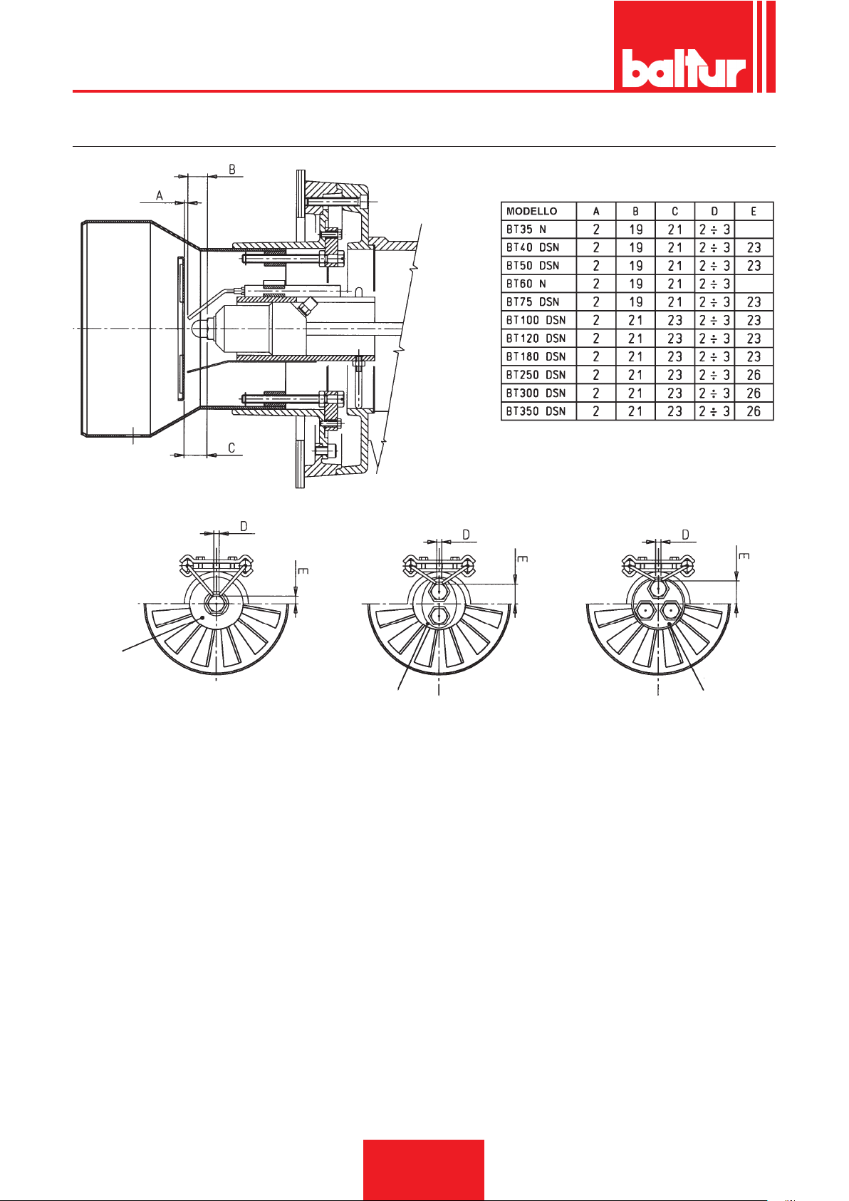
ITALIANO
SCHEMA INDICATIVO DISPOSIZIONE UGELLO - ELETTRODI - DISCO FIAMMA
N° 0002932311
Gruppo a 1 Ugello
1 nozzle atomizing group
Gruppo a 2 Ugelli
2 nozzles atomizing group
Gruppo a 3 Ugelli
3 nozzles atomizing group
30 / 40
0006080537_201610
Page 33
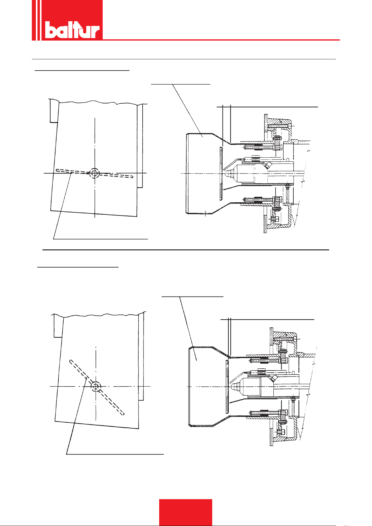
SCHEMA DI PRINCIPIO REGOLAZIONE ARIA
REGOLAZIONE NON CORRETTA
ITALIANO
Testa di combustione
Grande apertura di passaggio aria
Ingresso aria di combustione con serranda molto chiusa
REGOLAZIONE CORRETTA
N° 0002930890
Testa di combustione
Passaggio aria relativamente chiuso.
Attenzione: Evitare la chiusura completa
Ingresso aria di combustione con serranda sensibilmente aperta
31 / 40
0006080537_201610
Page 34
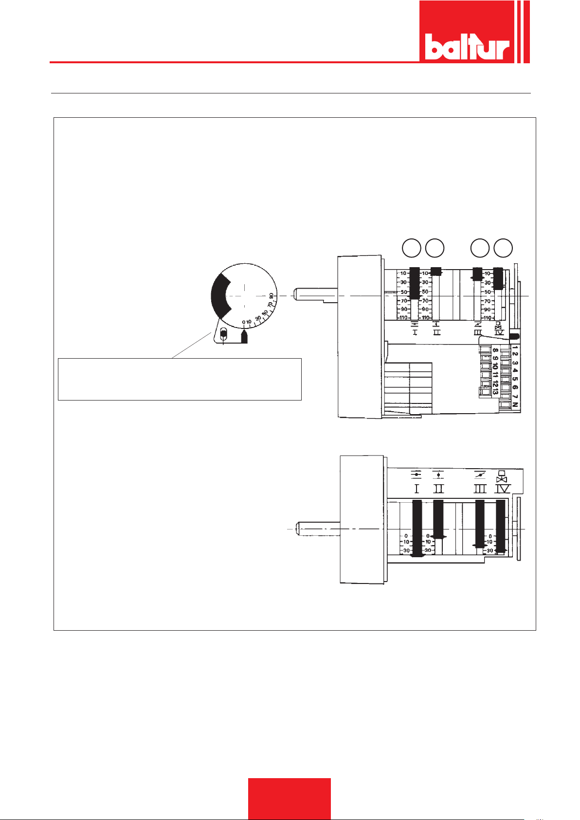
ITALIANO
SQN 30.111 A3500
- PREVENTILAZIONE CON ARIA APERTA (POSIZIONE 2° FIAMMA) ARIA CHIUSA CON BRUCIATORE FERMO
1 -
CAMMA inserzione valvola 2° amma (deve essere regolata in posizione intermedia tra la camma di 1° e quella di 2° amma)
2 - CAMMA regolazione aria 1° amma
3 - CAMMA serranda aria chiusa con bruciatore fermo
4 - CAMMA regolazione aria 2° amma
Perno di esclusione accoppiamento motore-albero cammes.
Premendo si ottiene la disinserzione del collegamento
motore e albero.
Per modificare la regolazione delle cammes si
agisce sui rispettivi anelli di colore rosso. Spingendo
con forza sufciente, nel senso voluto ogni anello
rosso può ruotare rispetto alla scala di riferimento.
L'indice dell'anello rosso indica sulla rispettiva scala
di riferimento l'angolo di rotazione impostato per ogni
camma.
34 1
2
8653-1
32 / 40
0006080537_201610
Page 35
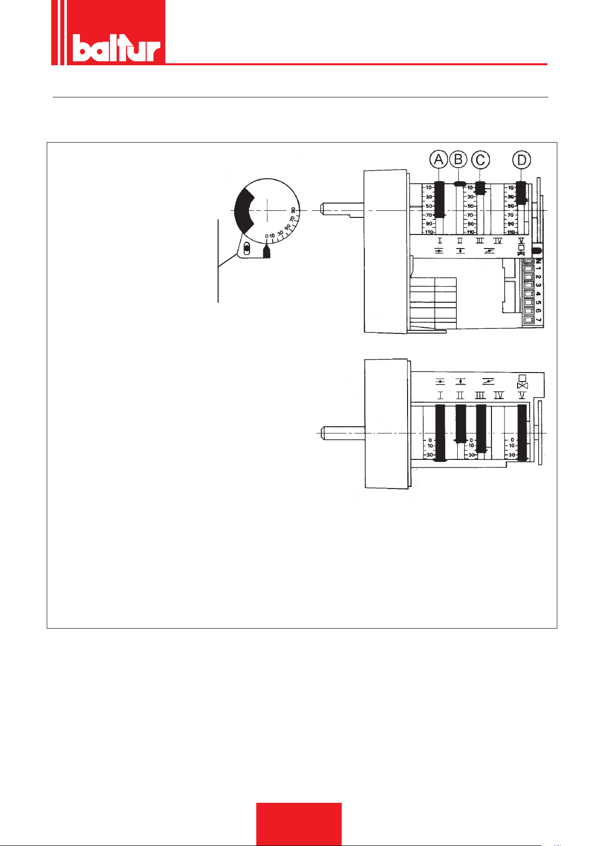
ITALIANO
SQN 30.121 A2700/3500
ARIA CHIUSA CON BRUCIATORE FERMO - PREVENTILAZIONE CON ARIA APERTA (POSIZIONE 1° FIAMMA) (CON APPARECCHIATURA LOA... o OR 3B)
- Perno di esclusione accoppiamento
motore - ambero cammes. Premendo si
ottiene la disinserzione del collegamento
motore albero.
8711-1
A - CAMMA regolazione aria 2° amma
B - CAMMA serranda aria chiusa con bruciatore fermo
C - CAMMA regolazione aria 1° amma
D - CAMMA inserzione valvola 2° amma
(deve essere regolata in posizione intermedia tra la
camma di 1° amma e quella di 2° amma)
Per modicare la regolazione delle cammes si agisce sui rispettivi anelli di colore rosso. Spingendo con forza
sufciente, nel senso voluto, ogni anello rosso può ruotare rispetto alla scala di riferimento. L’indice dell’anello
rosso indica sulla rispettiva scala di riferimento l’angolo di rotazione impostato per ogni camma.
33 / 40
0006080537_201610
Page 36
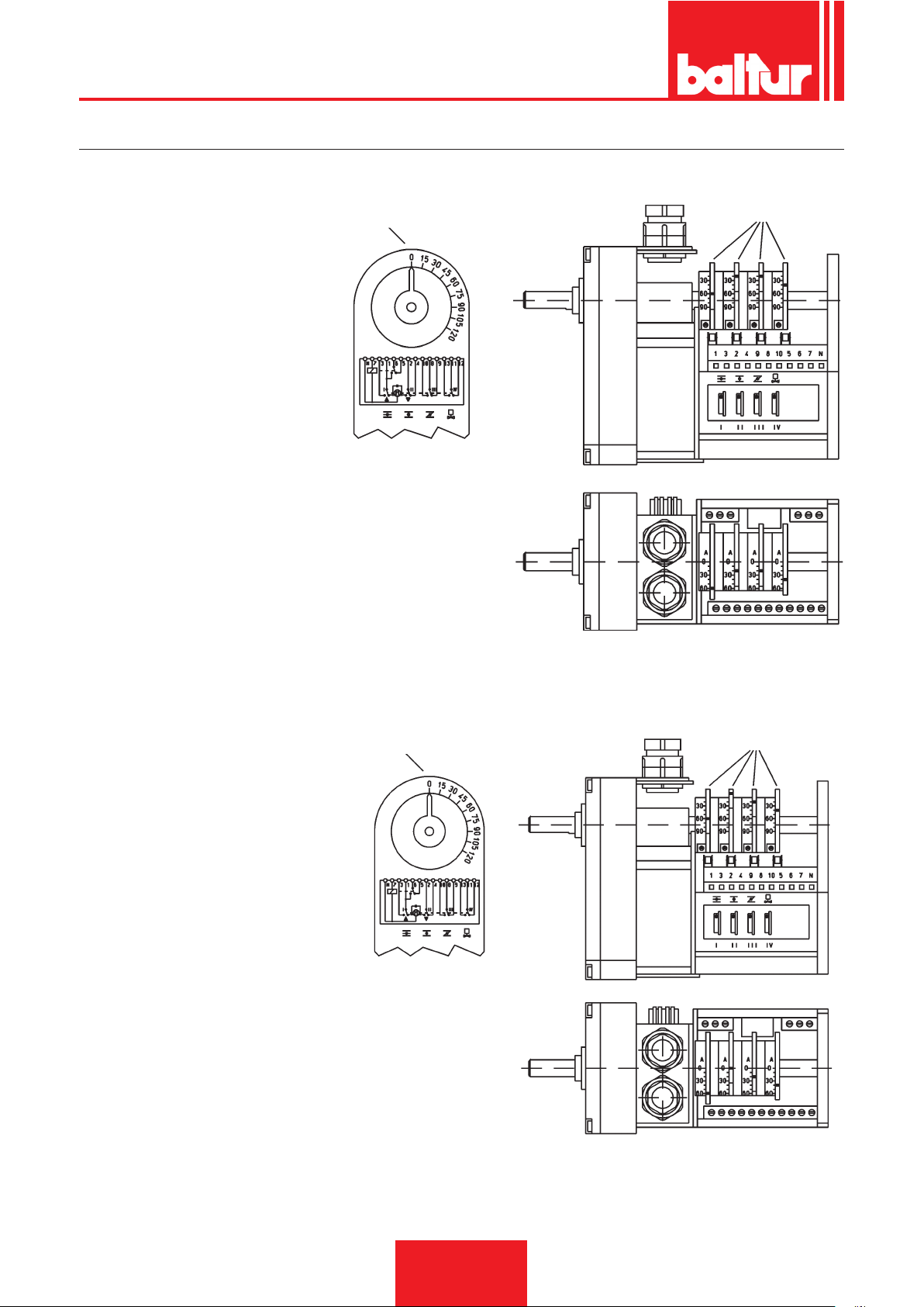
ITALIANO
“CONECTRON LKS 160”
REGOLAZIONE MOTORINO PER COMANDO SERRANDA ARIA 1° FIAMMA
I CAMMA REGOLAZIONE ARIA
2° FIAMMA (60°)
III CAMMA NON UTILIZZATA ( . . . °)
II CAMMA REGOLAZIONE ARIA
1° FIAMMA (20°)
IV CAMMA INSERZIONE VALVOLA
2° FIAMMA (40°)
nd
I 2
FLAME AIR ADJUSTING CAM (60°)
st
II 1
FLAME AIR ADJUSTING CAM (20°)
III CAM NOT USED ( . . . °)
nd
IV 2
FLAME VALVE ACTUATING CAM (40°)
INDICE DI RIFERIMENTO
CAMME REGOLABILI
0002934010
REGOLAZIONE MOTORINO PER COMANDO SERRANDA ARIA 2° FIAMMA
INDICE DI RIFERIMENTO
I CAMMA REGOLAZIONE ARIA 2° FIAMMA (60°)
II CHIUSURA TOTALE ARIA
(BRUCIATORE FERMO) (0°)
III CAMMA REGOLAZIONE ARIA 1° FIAMMA (20°)
IV CAMMA INSERZIONE
VALVOLA 2° FIAMMA (40°)
nd
FLAME AIR ADJUSTING CAM (60°)
I 2
II TOTAL AIR CLOSURE
(BURNER AT A STANDSTILL) (0°)
st
III 1
FLAME AIR ADJUSTING CAM (20°)
nd
IV 2
FLAME VALVE ACTUATING CAM (40°)
CAMME REGOLABILI
0002934000
34 / 40
0006080537_201610
Page 37
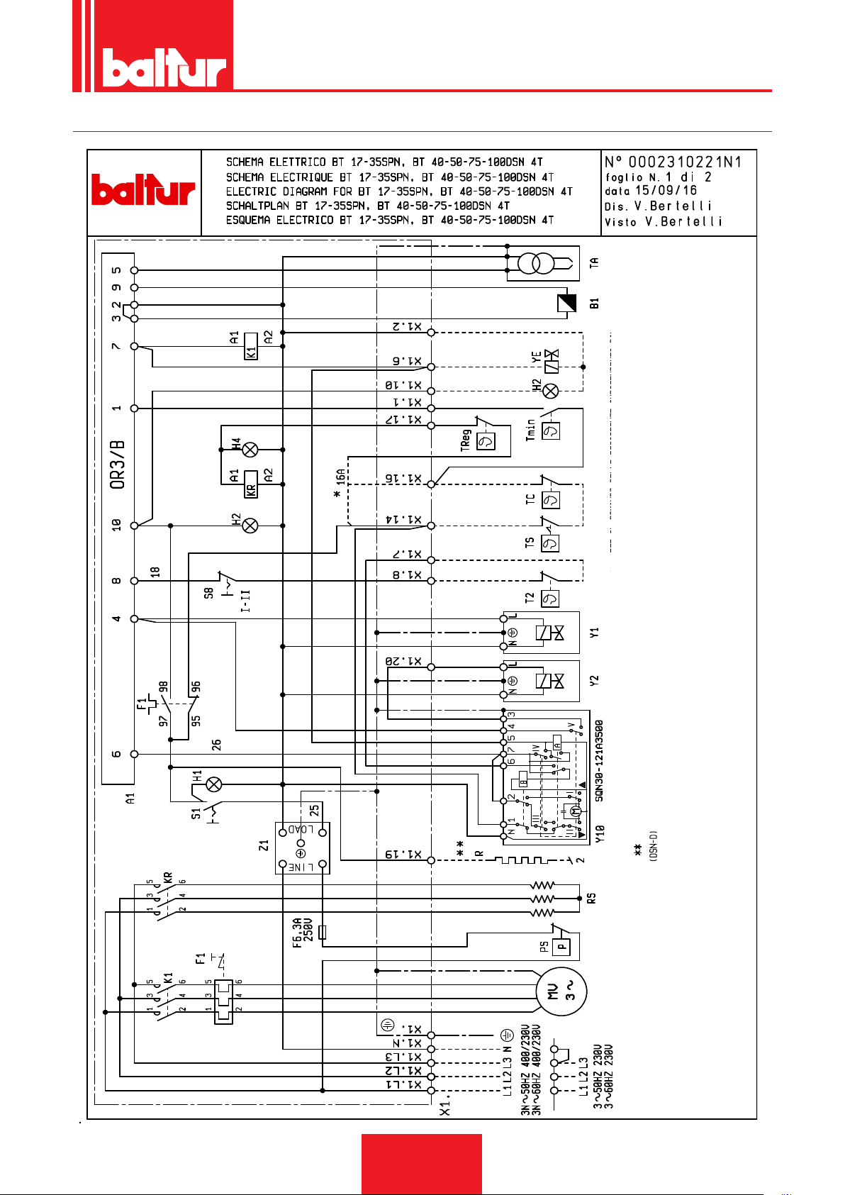
SCHEMA ELETTRICO
ITALIANO
"TC" SPOSTARE IL FILO 16A DAL MORSETTO 16 AL 14.
* PER IL COMANDO DELLE RESISTENZE INDIPENDENTI DAL
35 / 40
0006080537_201610
Page 38
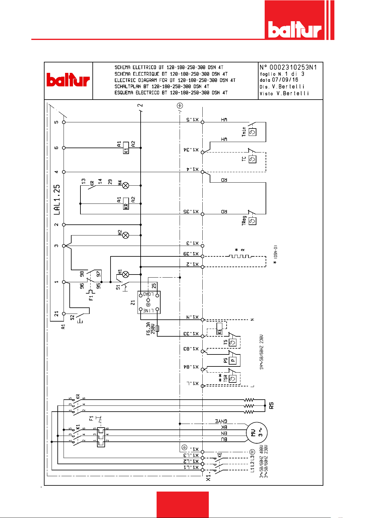
ITALIANO
36 / 40
0006080537_201610
** SOLO PER BT 180 - 250 - 300
Page 39
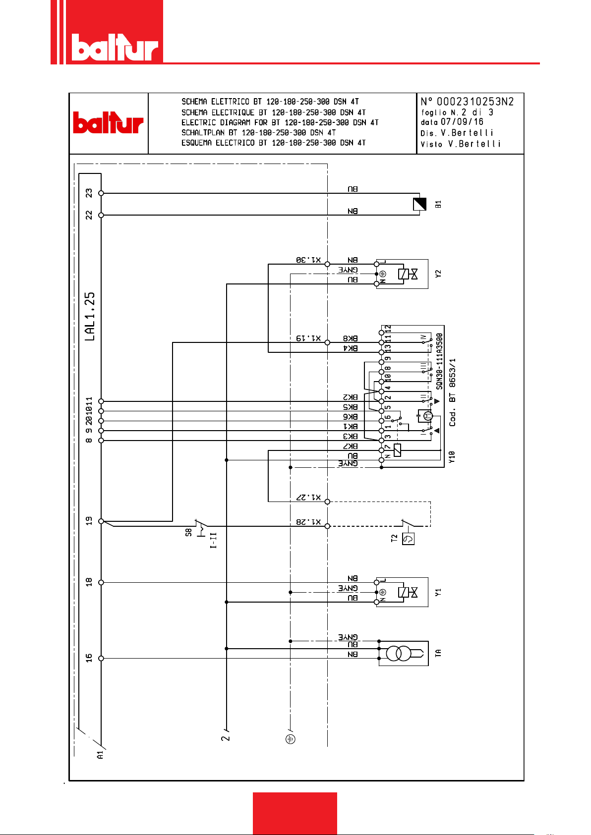
ITALIANO
37 / 40
0006080537_201610
Page 40
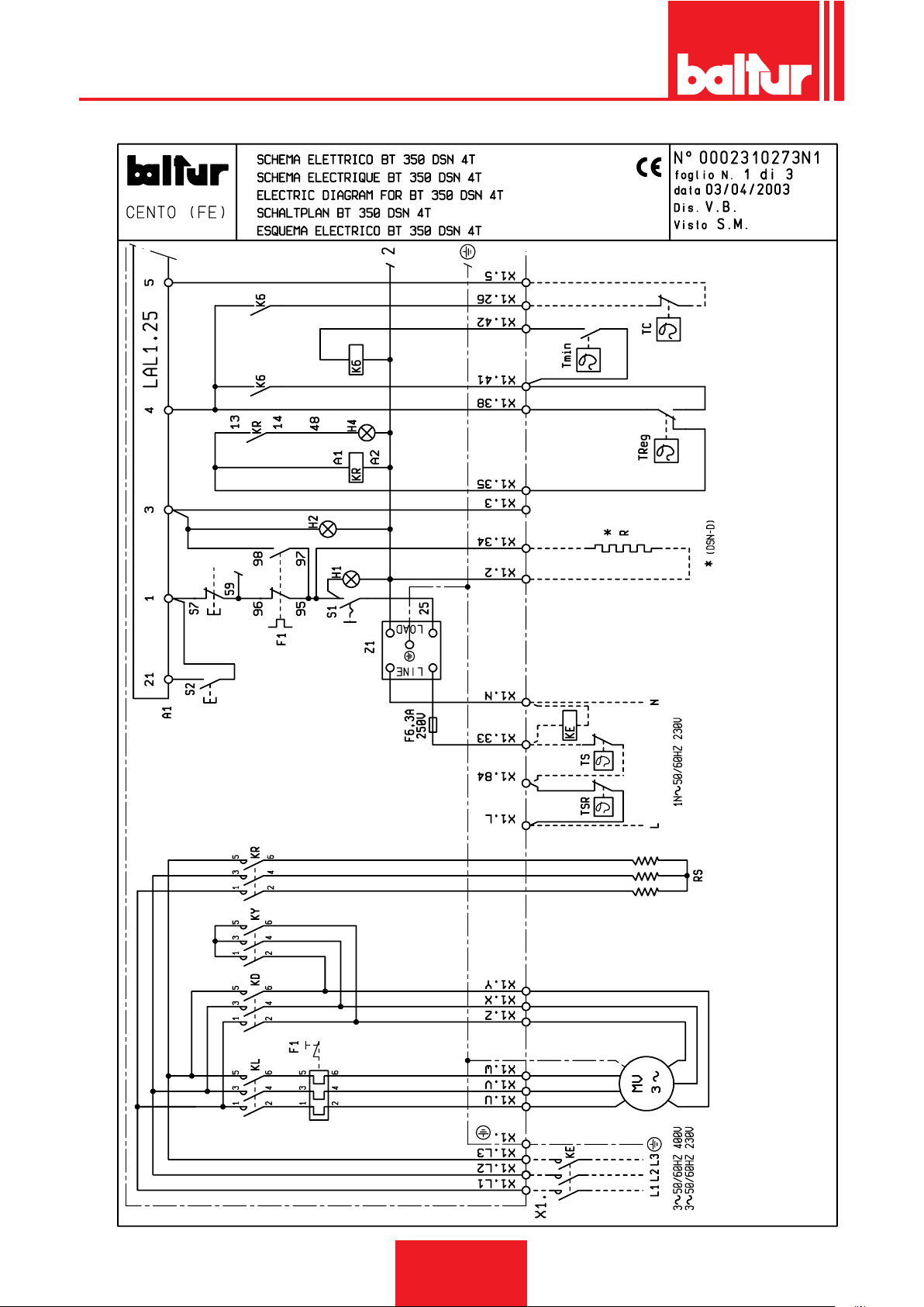
ITALIANO
38 / 40
0006080537_201610
Page 41
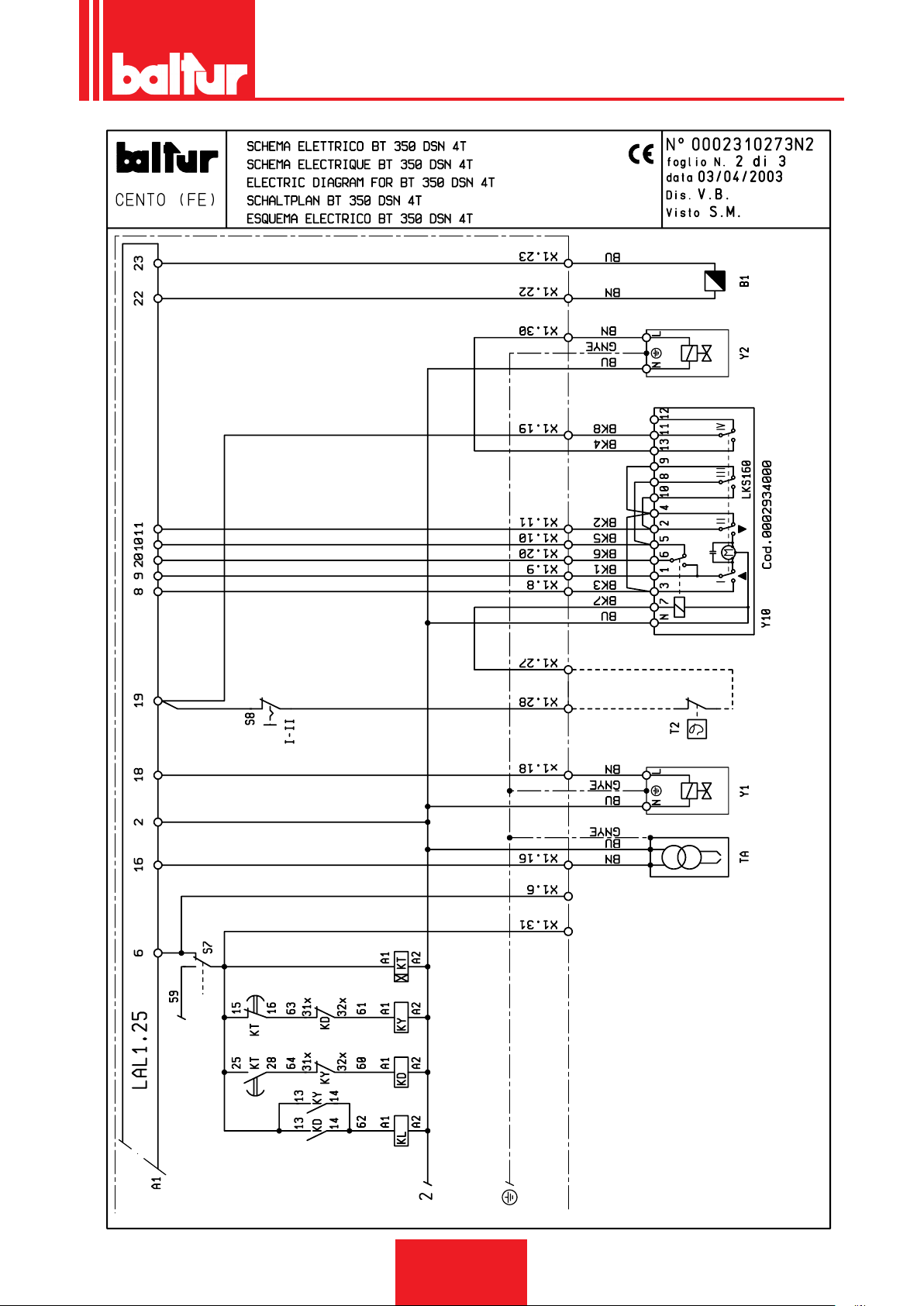
ITALIANO
39 / 40
0006080537_201610
Page 42

ITALIANO
SIGLA IT
A1 APPARECCHIATURA
B1 - FR FOTORESISTENZA
F1 RELE’ TERMICO
F2 RELE' TERMICO POMPA
HO SPIA BLOCCO ESTERNA / LAMPADA FUNZIO-
NAMENTO RESISTENZE AUSILIARIE
H1 SPIA DI FUNZIONAMENTO
H2 SPIA DI BLOCCO
H4 SPIA RESISTENZE
K1 RELE’ MOTORE
K2 CONTATTORE MOTORE POMPA
K6 RELE’ AUSILIARIO PER RESISTENZE
KD CONTATTORE TRIANGOLO
KE CONTATTORE ESTERNO
KL CONTATTORE DI LINEA
KR CONTATTORE RESISTENZE
KT TEMPORIZZATORE
KY CONTATTORE DI STELLA
MP MOTORE POMPA
MV MOTORE VENTOLA
PA PRESSOSTATO ARIA
PS PRESSOSTATO SICUREZZA
RP.RF.RG RESISTENZE POMPA,FILTRO,GRUPPO
RS - R RESISTENZE
S1 INTERRUTTORE MARCIA ARRESTO
S2 PULSANTE SBLOCCO
S7 PULSANTE CARICAMENTO SERBATOIO
S8 INTERRUTTORE 1° - 2° STADIO
T2 TERMOSTATO 2 STADIO
TA TRASFORMATORE D'ACCENSIONE
TC TERMOSTATO CALDAIA
Tmin TERMOSTATO DI MINIMA
Treg TERMOSTATO REGOLAZIONE RESISTENZE
TS TERMOSTATO DI SICUREZZA
TSR TERMOSTATO SICUREZZA RESISTENZE
X1 MORSETTIERA BRUCIATORE
YE - VE ELETTROVALVOLA ESTERNA
Y1/Y2 - V1/V2 ELETTROVALVOLE 1° / 2° STADIO
Y10 SERVOMOTORE ARIA
YS - VS ELETTROVALVOLA DI SICUREZZA
Z1 - Z FILTRO
40 / 40
0006080537_201610
Page 43

ENGLISH
DECLARATION OF CONFORMITY
CE0085:
DVGW CERT GmbH, Josef-Wirmer Strasse 1-3-53123 Bonn (D)
We hereby declare under our own responsibility, that our domestic and industrial blown air burners red by gas, oil and dual fuel, series:
BPM...; BGN…; BT…; BTG…; BTL…; TBML...; Comist…; GI…; GI…Mist; Minicomist…; PYR…; RiNOx…; Spark...; Sparkgas...;
TBG...;TBL...; TS…; IBR...; IB...
(Variant: … LX, for low NOx emissions)
respect the minimal regulation of the European Directives:
• 2009/142/CE (D.A.G.)
• 2004/108/CE (C.E.M.)
• 2006/95/CE (D.B.T.)
• 2006/42/CE (D.M.)
and compliant with the European Standards:
• prEN 676:2012 (gas and dual fuel, gas side)
• prEN 267:2012 (diesel and dual fuel, diesel side)
• EN 60335-1 (2012-01) + EC (2014-01) (all burners)
Cento, 12 Genuary 2015
Director of Research & Development
Paolo Bolognin
Managing Director and General Manager
Riccardo Fava
1 / 38
0006080547_201610
Page 44

ENGLISH
INSTRUCTIONS FOR USE IN SAFE CONDITIONS
PURPOSE OF THE MANUAL
The manual purpose is to contribute to the safe use of the product,
indicating the conduct and behaviour required to prevent alterations to the safety features of the apparatus which could derive
from incorrect installation or incorrect, unauthorised or unreasonable uses.
The manufacturer is not liable contractually or extra contractually
for any damage caused by errors in installation and in use, or
where there has been any failure to follow the manufacturer’s instructions.
• The machines produced have a minimum life of 10 years, if the
normal working conditions are respected and if periodic maintenance specied by the manufacturer is made.
• The instruction booklet is an integral and essential part of the
product and must be given to the user.
• The user must keep the booklet with care for any future consultation.
• Carefully read the “Instruction for use” in this manual and
the instructions indicated on the product before using the
equipment in order to minimise risks and avoid accidents.
• Follow the SAFETY INSTRUCTIONS carefully. Avoid IMPROPER USES.
• The installer must assess RESIDUAL RISKS that might remain.
• Symbols are used to draw your attention to some parts of the
text or to indicate some important precautions. Their meaning
is described below.
DANGER / CAUTION
This symbol indicates a serious danger, that if ignored, can
seriously put at risk the health and safety of the operator.
CAUTION / WARNING
This symbol indicates that a proper conduct must be adopted in order not to put at risk the health and safety of people
and cause economic damage.
IMPORTANT
This symbol indicates particularly important technical and
operational information.
gh the intermediation of a responsible person, of information
regarding their safety, of surveillance, of instructions concerning
its use.
• Children should be supervised to ensure that they do not play
with the device.
• This appliance should only be used for the purpose it has been
designed for. Any other use is to be considered improper and
therefore dangerous.
• The equipment must be installed in accordance with current
regulations, following the manufacturer’s instructions and by
qualied technicians.
• The term ‘qualied personnel’ refers to personnel specically
trained and with proven skills in the eld of heating according to
the local legislation in force.
• An incorrect installation can cause injury or damage to persons,
animals and objects, for which the manufacturer cannot be held
responsible.
• After removing all the packaging make sure the contents are
complete and intact. If in doubt do not use the equipment and
return it to the supplier. The packing is potentially dangerous
and must be kept away from children.
• The majority of the equipment components is made of reusable
material. The package and the equipment cannot be disposed
of with the standard waste but according to the regulations in
force.
• Before carrying out any cleaning or maintenance, disconnect
the equipment at the mains supply, using the system’s switch
and/or shut-off systems.
• If the equipment is sold or transferred to another owner or if the
owner moves and leaves the equipment, make sure that the
booklet always goes with the equipment so it can be consulted
by the new owner and/or installer.
• With the equipment operating do not touch the hot parts usually
located near the ame or the fuel pre-heating system, if present.
These parts can remain hot even after a non prolonged stop of
the equipment.
• For all equipment with optionals or kits (including electrical
ones), only original accessories must be used.
CONDITIONS AND DURATION OF STORAGE
The equipment is shipped with the manufacturer package and
transported on road, by boat or by train in compliance with the
standards on goods transport in force for the actual mean of transport used.
The unused equipment must be placed in closed rooms with
enough air circulation in standard conditions (temperature betwe-
en -10° C and + 40° C).
The storage time is 3 years.
GENERAL INSTRUCTIONS
• The equipment production date (month, year) is written on the
burner identication plate located on the equipment.The device
is not suitable to be used by persons (including children) with
reduced physical, sensory or mental capacities, or lack of expe-
rience or knowledge.
• such persons can use the device only if they can benet, throu-
0006080547_201610
2 / 38
Page 45

ENGLISH
• If there is any fault and/or if the equipment is not working pro-
perly, de-activate the equipment and do not attempt to repair it
or tamper with it directly. Contact only qualied personnel.
• Any product repairs must only be carried out by BALTUR autho-
rised assistance centres or its local retailer using only original
spare parts.
• The manufacturer and/or its local retailer decline any liability
for injuries or damage caused by unauthorised modications of
the product or non-observance of the instructions contained in
the manual.
SAFETY INSTRUCTIONS FOR INSTALLATION
• The equipment must be installed in a suitable area with ade-
quate ventilation according to the standards and regulations in
force.
• The slots of the air extraction grilles and installation room venti-
lation openings must not be obstructed even partially.
• In the installation site there must NOT be any risk of explosion
and/or re.
• Thoroughly clean the inside of all pipes of the fuel supply system before installation.
• Before connecting the burner check that the details on the plate
correspond to those of the utility supplies (electricity, gas, diesel
or other fuel).
• Make sure that the burner is rmly fastened to the heat genera-
tor according to the manufacturer's instructions.
• Make the connections to the power sources properly as indi-
cated in the explanatory diagrams and following the standards
and regulations in force at the moment of installation.
• Check that the fume exhaust system is NOT obstructed.
• If you decide not to use the burner any more, the following pro-
cedures must be performed by qualied technicians:
- Switch off the electrical supply by disconnecting the power
cable from the main switch.
- Cut off the fuel supply using the shut-off valve and remove
the control wheels from their position.
- Render harmless any potentially dangerous parts.
- Check the combustion adjusting the comburent and/or fuel
air ow to optimise the combustion performance and emissions according to the regulations in force.
- Check the regulation and safety devices are working
properly.
- Check for the correct operation of the combustion products
exhaust duct.
- Check for the seal of fuel supply pipes in their internal and
external parts.
- At the end of the adjustment procedures, check that all
the mechanical locking devices of regulation systems are
properly tightened.
- Make sure that the burner use and maintenance manual are
available and within your reach.
• If the burner repeatedly shuts down in lock-out, do not keep
trying to manually reset it but call a qualied technician to solve
the unexpected problem.
• If you decide not to use the burner for a while, close the valve or
valves that supply the fuel.
INSTRUCTIONS FOR START-UP, INSPECTION, USE AND
MAINTENANCE
• Start-up, inspection and maintenance of the equipment must
only be carried out by qualied technicians, in compliance with
current regulations.
• Once you have fastened the burner to the power generator,
make sure that during testing the ame produced does not
come out of any slots.
• Check for the seal of fuel supply pipes connected to the
equipment.Check that the fuel ow rate matches the power required by the burner.
• Set the burner fuel capacity to the power required by the heat
generator.
• The fuel supply pressure must lie between the values indicated
on the data plate located on the burner and/or in the manual
• The fuel supply system is suitably sized for the ow required
by the thermal module and that it has all the safety and control
devices required by current standards.
• Before starting up the burner, and at least once a year, have
qualied technicians perform the following procedures:
- Set the burner fuel capacity to the power required by the
heat generator.
0006080547_201610
3 / 38
Page 46

ENGLISH
Special instructions for using gas.
• Check that the feed line and the train comply with current stan-
dards and regulations.
• Check that all the gas connections are properly sealed.
• Do not leave the equipment on when it is not in use and always
close the gas cock.
• If the user is away for some time, close the main gas feed valve
to the burner.
• If you smell gas:
- do not operate electrical switches, the phone or any other
object that can cause sparks;
- immediately open doors and windows to create a draught to
clear the air in the room;
- close the gas cocks;
- have professionally qualied personnel correct the fault.
• Do not block ventilation openings in the room where there is gas
equipment or dangerous situations may arise with the build up
of toxic and explosive mixtures.
RESIDUAL RISKS
• In spite of the accurate product planning according to the regu-
lations in force, residual risks may still be present during correct
use. They are indicated on the burner by means of specic Pictograms.
CAUTION
Mechanical parts in motion.
to the burner.
• The use of any components that use electricity means that cer-
tain fundamental rules have to followed, including the following:
- do not touch the equipment with parts of the body that are
wet or damp and/or with damp feet
- do not pull on electrical cables;
- do not leave the equipment exposed to atmospheric agents
(such as rain or sun etc.) unless there is express provision
for this.
- do not allow the equipment to be used by children or inexperienced persons.
- The power supply cable for the equipment not must be
replaced by the user. If the cable is damaged, turn off the
equipment. To replace the cable, contact exclusively qualied personnel.
- If you decide not to use the equipment for a while it is advisable to switch off the electrical power supply to all components in the system that use electricity (pumps, burner, etc.).
CAUTION
Materials at high temperatures.
CAUTION
Energised electrical switchboard
INSTRUCTIONS ON ELECTRICAL SAFETY
• Check that the equipment is properly grounded according to the
safety standards in force.
• Do not use the gas pipes to ground electrical equipment.
• If in doubt, call for a careful electrical check by a qualied technician, since the manufacturer will not be liable for any dama-
ge caused by a poor ground connection.A professional check
should be carried out to ensure that the electrical installation is
adequate for the maximum output absorbed by the system. This
is indicated on the data plate.
• Make sure that the system cable cross-section is suitable for
the power absorbed by the equipment.
• The use of adaptors, multiple plugs and/or extension leads to
supply power from the mains to the appliance is not allowed.
• For the connection to the mains, t an omnipolar switch with a
contact opening gap equal to or greater than 3 mm in accordance with current safety regulations (Overvoltage category III).
• Use only double insulated cables with external thickness of at
least 1mm for the power supply of the burner.
• Unsheathe the external insulating cover of the power cable to
the necessary extent for the connection, thus avoiding the wire
from coming into contact with metal parts.
• The electrical supply to the burner must have neutral to ground
connection. In the case of a ionisation current check with neu-
tral not to ground, it is essential to make a connection between
terminal 2 (neutral) and the ground for the RC circuit.
• If the user is away for some time, close the main gas feed valve
4 / 38
0006080547_201610
Page 47

TECHNICAL SPECIFICATIONS
ENGLISH
PORTATA / FLOW RATE MIN Kg/h
MAX Kg/h
POTENZA TERMICA
THERMIC CAPACITY
VISCOSITA’ COMBUSTIBILE
FUEL VISCOSITY
MOTORE VENTOLA / FAN MOTOR kW
MIN kW
MAX kW
vers. normale
normal version
versione Denso
heavy oil version
r.p.m. 2800 2800 2800 2810 2825
TRASFORMATORE / TRANSFORMER VOLT/VOLTIOS
TENSIONE / VOLTAGE TRIFASE
RESISTENZA PRERISCALDATORE
PRE-HEATER RESISTANCES
THREE PHASE
kW
MATERIALI A CORREDO / ACCESSORIES
BT 40
DSN-4T
BT 50
DSN-4T
BT 75
DSN-4T
BT 100
DSN-4T
BT 120
DSN-4T
20 28 40 50 60
40 50 75 100 130
223 312 446 558 669
446 558 837 1116 1451
7°E - 50°C 7°E - 50°C 7°E - 50°C 7°E - 50°C 7°E - 50°C
20°E - 50°C 20°E - 50°C 20°E - 50°C 20°E - 50°C 20°E - 50°C
0,55 1,1 1,1 1,5 2,2
10kV -
30mA
10kV -
30mA
10kV -
30mA
12kV -
30mA
12kV -
30mA
3 N ~ 400V ± 10% 50 Hz
3,2 6 6 7,5 10,5
GUARNIZIONE ISOLANTE /
ISOLATING GASKET
PRIGIONIERI / STUD BOLTS
DADI ESAGONALI / HEXAGONAL NUTS
ROSETTE PIANE / FLAT WASHERS
TUBI FLESSIBILI - FLEXIBLE PIPES
NIPPLI / NIPPLES
FILTRO - FILTER
N° 1 N° 1 N° 1 N° 1 N° 1
N° 4 - M12 N° 4 - M12 N° 4 - M12 N° 4 - M16 N° 4 - M16
N° 4 - M12 N° 4 - M12 N° 4 - M12 N° 4 - M16 N° 4 - M16
N° 4 - Ø12 N° 4 - Ø12 N° 4 - Ø12 N° 4 - Ø16 N° 4 - Ø16
N°1 - 3/4”
N°1 - 1”
N°1 - 3/4”x1” N°1 - 3/4”x1” N°1 - 3/4”x1” N°1 - 3/4”x1” N°1 - 3/4”x1”
N°1 - 1”x1” N°1 - 1”x1” N°1 - 1”x1” N°1 - 1”x1” N°1 - 1”x1”
1” 1” 1” 1” 1”
N°1 - 3/4”
N°1 - 1”
N°1 - 3/4”
N°1 - 1”
N°1 - 3/4”
N°1 - 1”
N°1 - 3/4”
N°1 - 1”
5 / 38
0006080547_201610
Page 48
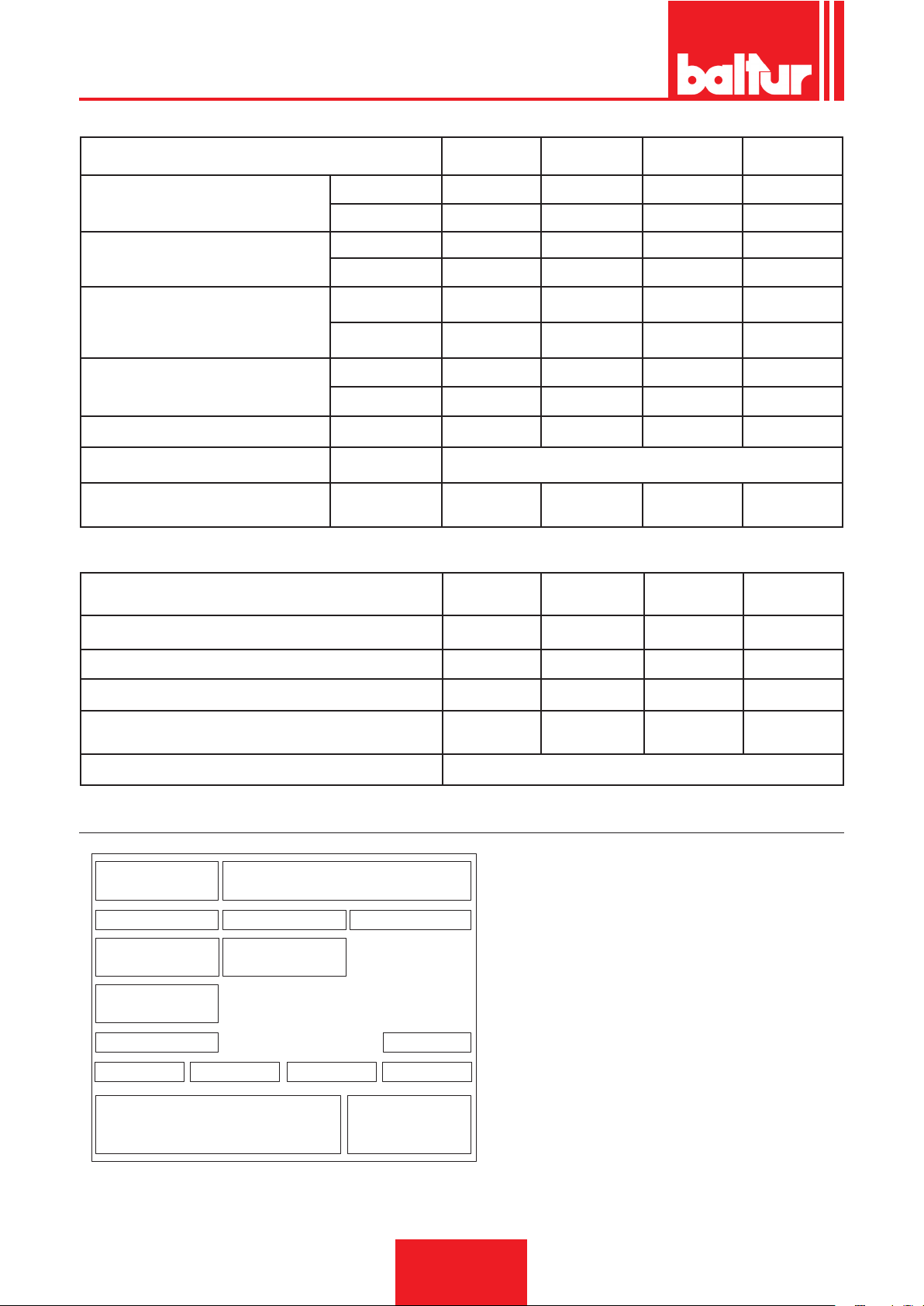
Targa_descr_bru
ENGLISH
MIN Kg/h
PORTATA / FLOW RATE
POTENZA TERMICA
THERMIC CAPACITY
VISCOSITA’ COMBUSTIBILE
FUEL VISCOSITY
MOTORE VENTOLA / FAN MOTOR
TRASFORMATORE / TRANSFORMER / VOLT/VOLTS
TENSIONE / VOLTAGE / TENSÍON
RESISTENZA PRERISCALDATORE
PRE-HEATER RESISTANCES
MAX Kg/h
MIN kW
MAX kW
vers. normale
normal version
versione Denso
heavy oil version
kW
r.p.m. 2870 2870 2870 2900
TRIFASE
THREE PHASE
MATERIALI A CORREDO / ACCESSORIES
GUARNIZIONE ISOLANTE /
ISOLATING GASKET
BT 180
DSN-4T
65 90 110 115
180 280 325 350
725 937 1220 1284
2009 3170 3460 3907
7° E - 50° C 7° E - 50° C 7° E - 50° C 7° E - 50° C
20° E - 50° C 20° E - 50° C 20° E - 50° C 20° E - 50° C
3 7,5 7,5 9
14kV - 30mA 14kV - 30mA 14kV - 30mA 14kV - 30mA
kW
15 18 25,5 28,5
BT 250
DSN-4T
3 N ~ 400V ± 10% 50 Hz
BT 300
DSN-4T
N° 1 N° 1 N° 1 N° 1
BT 350
DSN-4T
PRIGIONIERI / STUD BOLTS N° 4 - M16 N° 4 - M16 N° 4 - M18 N° 4 - M18
DADI ESAGONALI / HEXAGONAL NUTS N° 4 - M16 N° 4 - M16 N° 4 - M18 N° 4 - M18
ROSETTE PIANE / FLAT WASHERS N° 4 - Ø16 N° 4 - Ø16 N° 4 - Ø18 N° 4 - Ø18
TUBI FLESSIBILI - FLEXIBLE PIPES
N°1 - 3/4"
N°1 - 1"1/4
N°1 - 3/4"
N°1 - 1"1/4
N°2 - 1" 1/4 N°2 - 1" 1/4
FILTRO - FILTER 1”1/4
BURNER IDENTIFICATION PLATE
1 Company logo
1 2
3 4 5
6 7
8
9
10 13
11
12
14
1615
2 Company name
3 Product code
4 Model
5 Serial number
6 Liquid fuel power
7 Gas fuel power
8 Gas fuel pressure
9 Liquid fuel viscosity
10 Fan motor power
11 Power supply voltage
12 Protection rating
13 Country of manufacture and homologation certicate num-
bers
14 Year of manufacture
15 16 Burner serial number bar code
6 / 38
0006080547_201610
Page 49
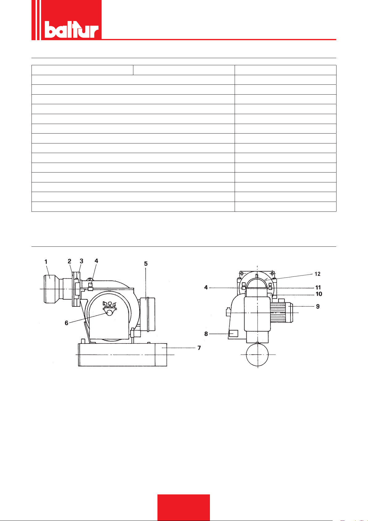
FIRST START UP RECORDING DATA
Model: Date: Now:
Type of gas
Lower Wobbe number
Lower caloric power
Gas ow
Min. gas ow rate
Max. gas ow rate
Min. gas power
Max. gas power
Network gas pressure
Gas pressure downstream of the stabiliser
CO
CO2
fume temperature
air temperature
Stm3/h
Stm³/h
Stm³/h
kW
kW
mbar
mbar
ENGLISH
COMPONENT DESCRIPTION
1) COMBUSTION HEAD
2) INSULATING GASKET
3) HINGE
4) 1st FLAME ELECTROVALVE (usually closed)
5) ELECTRIC BOARD
6) PUMP
7) PRE-HEATER
8) AIR REGULATION SERVOMOTOR
9) FAN MOTOR
10) IGNITION TRANSFORMER
11) 2nd FLAME ELECTROVALVE (usually open)
12) PHOTORESISTANCE
02370281A-tif
7 / 38
0006080547_201610
Page 50
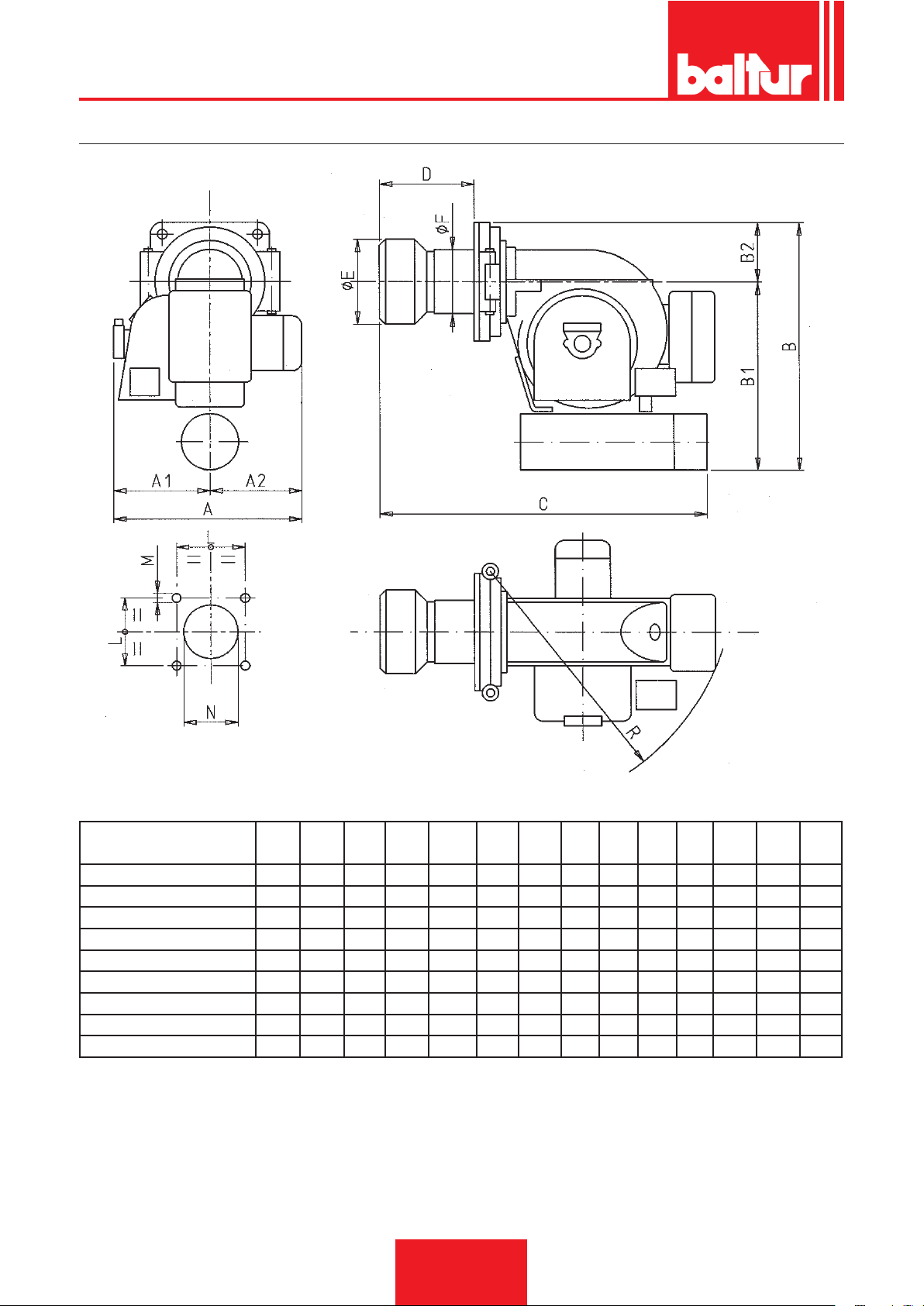
ENGLISH
OVERALL DIMENSIONS
02370281B-tif
MODELLO / MODEL A A1 A2 B B1 B2 C D E F L M N R
Ø Ø Ø
BT 40 DSN 4T/DSN 4T-D 560 300 260 615 465 150 735 145 155 135 230 M 12 170 595
BT 50 DSN 4T/DSN 4T-D 660 340 320 730 580 150 835 145 155 135 230 M 12 170 705
BT 75 DSN 4T/DSN 4T-D 660 340 320 740 580 150 910 220 205 170 230 M 12 220 705
BT 100 DSN 4T/DSN 4T-D 660 340 320 740 580 150 965 265 230 195 240 M 12 240 705
BT 120 DSN 4T/DSN 4T-D 690 320 370 825 665 160 1125 265 230 195 240 M 12 240 865
BT 180 DSN 4T/DSN 4T-D 755 385 370 900 720 180 1210 280 260 225 280 M 16 275 940
BT 250 DSN 4T/DSN 4T-D 945 465 480 1030 850 180 1235 295 260 225 280 M 16 275 940
BT 300 DSN 4T/DSN 4T-D 945 465 490 1170 945 225 1530 420 356 280 360 M 16 370 1135
BT 350 DSN 4T/DSN 4T-D 1085 525 560 1225 1000 225 1530 420 356 280 360 M 16 370 1135
8 / 38
0006080547_201610
Page 51
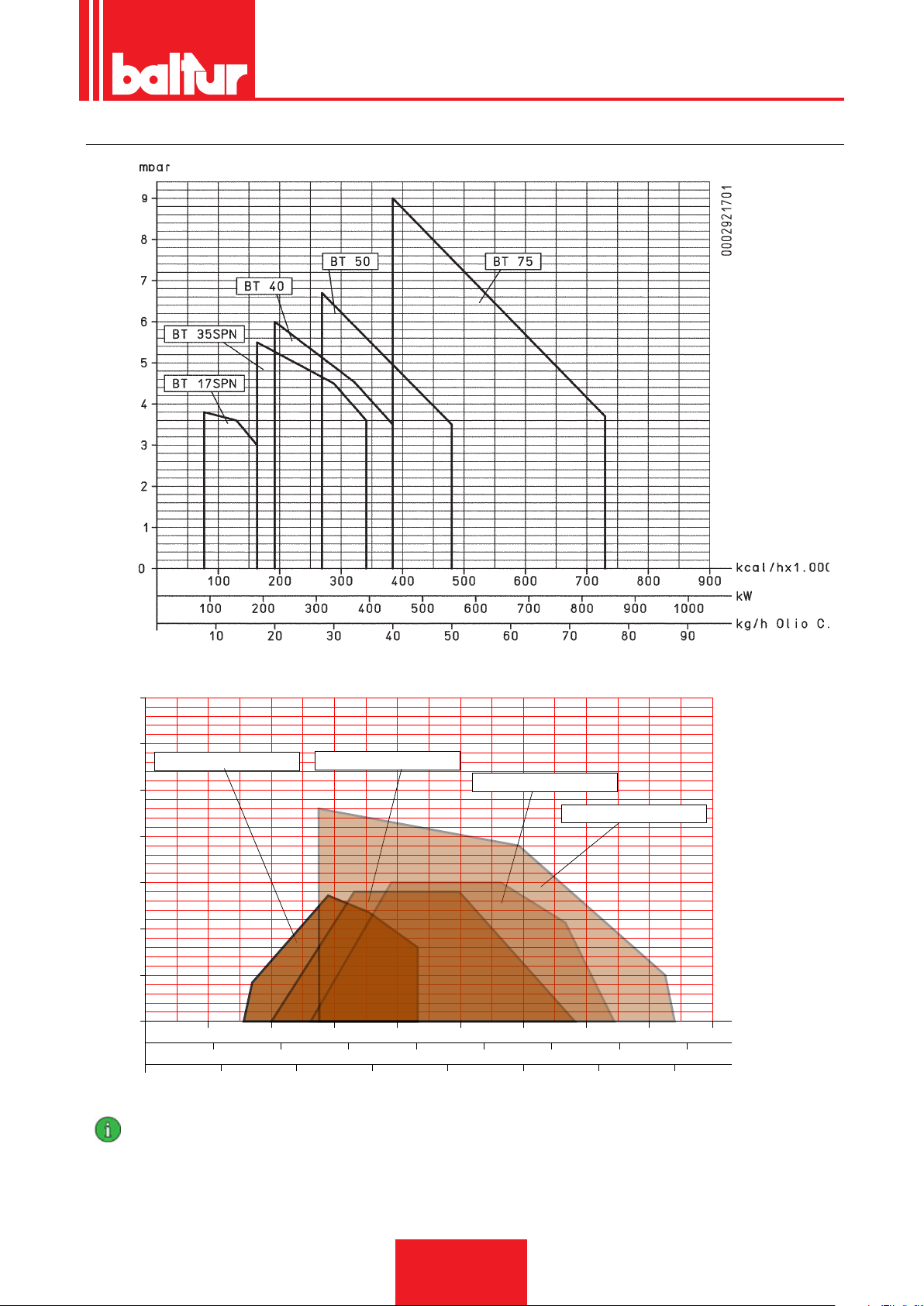
WORKING FIELD
40 80
160
200
1000
240 280 320 360
kcal/hx10.000
2000 3000
4000
50
100 150
200 250 300 350
5
10
15
20
0
25
30
500
1500
2500 3500
35
120
0002921710
kW
kg/h
mbar
BT 180 DSPN / DSNM-D
BT 250 DSPN / DSNM-D
BT 300 DSPN / DSNM-D
BT 350 DSPN / DSNM-D
ENGLISH
IMPORTANT
The working elds are obtained from test boilers corresponding to the standard EN267 and are indicative for the combination
burner-boiler. For correct working of the burner, the size of the combustion chamber must correspond to current regulations; if not
the manufacturers must be consulted.
The burner should not work outside the indicated work range.
0006080547_201610
9 / 38
Page 52
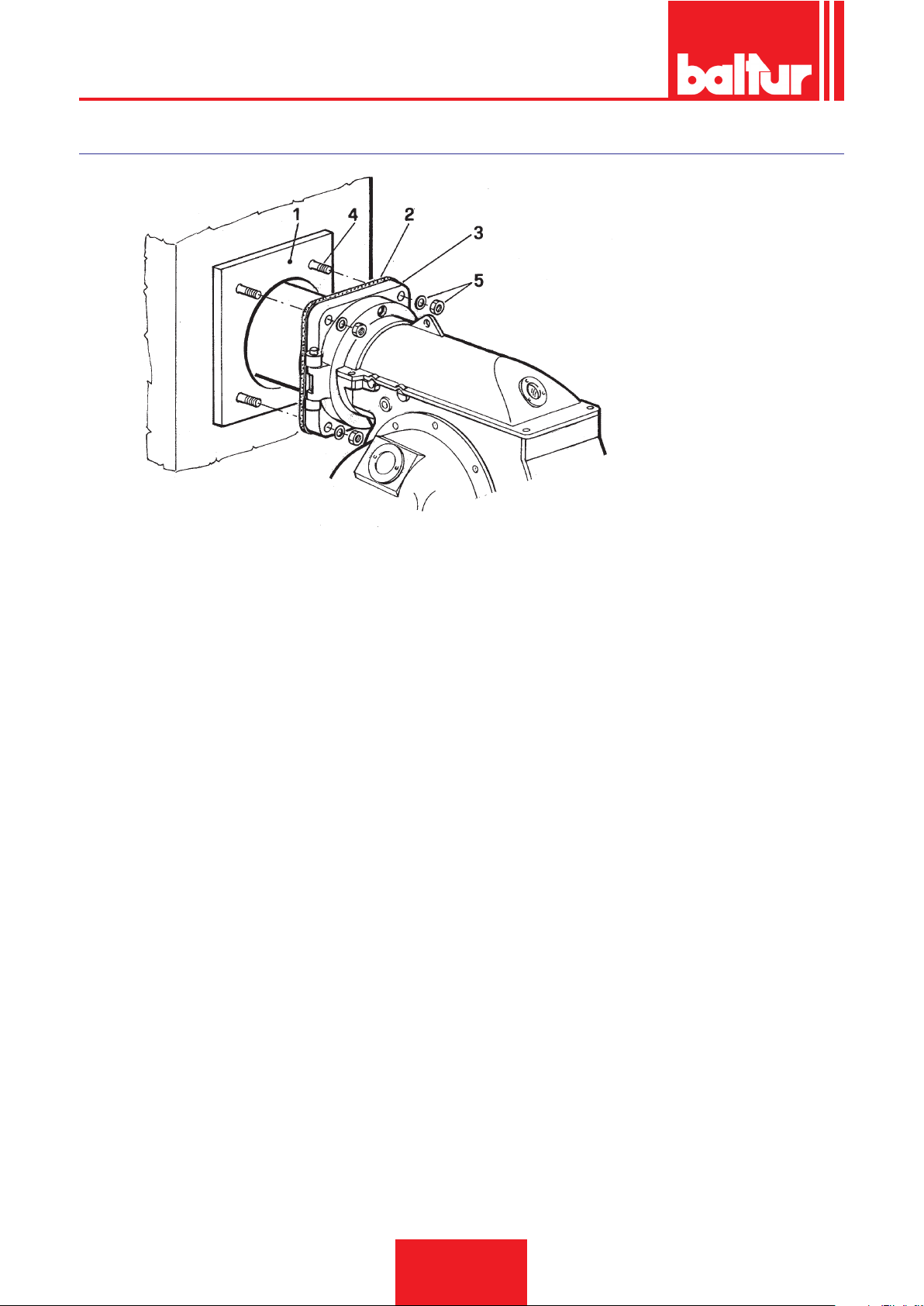
ENGLISH
APPLICATION OF THE BURNER TO BOILER
N° 0002933630
1 - Boiler plate
2 - Insulating gasket
3 - Burner xing ange
4 - Stud bolt
5 - Locking nut with washer
REMARKS
The burner's head penetration depth, into the boiler's combustion chamber, must be specied by the boiler's manufacturer.
The burner is correctly tted if the preheating tank is slightly tilted (i.e. higher on the fuel outlet side towards the nozzle).
This slight tilt prevents any build-up of gas inside the tank.
The presence of gas inside the preheating tank will considerably lengthen the time required to get the fuel up to pressure. Therefore the
burner could easily lock-out. When tting the burner to the boiler make sure that it is not positioned in a way that cancels out this tilt or,
even worse, that the preheater is tilted the opposite way.
10 / 38
0006080547_201610
Page 53

ENGLISH
INSTRUCTIONS FOR PROPER INSTALLATION
Before proceeding with installation make sure that:
1) The ue (cross-section and height) corresponds to the regulations in force.
2) When refractory lining of the combustion chamber is necessary (where the boiler type so requires) you must
follow the boiler manufacturer’s instructions to the letter.
3) The burner electricity supply must be connected up as illustrated in our diagram and on-burner electrical connections must be compatible with power supply voltage.
4) Fuel lines must be set up as illustrated in our diagrams.
5) The burner nozzle (or nozzles) must be compatible with the boiler output. Replace with others if necessary.
Under no circumstances must the fuel ow-rate be greater than the maximum required by the boiler or maxi-
mum admissible burner ow-rates. Bear in mind that the combustion head has been designed for nozzles with a
45° spray angle. Only in exceptional cases may nozzles of a different angle be tted: in such cases make sure
that these differently-angled nozzles do not cause any problems (ame detachment, staining of diffuser disc
or combustion head, violent ignition, etc.).
6) Exercise caution during removal of the protective plastic nozzle plug: if the seal is compromised
(a slight scratch will damage it) the fuel could drip.
7) Make sure that the burner draught tube penetrates the combustion chamber as per the boiler manufacturer’s
specications.
ELECTRICAL CONNECTIONS
All connections must be carried out with exible wiring.
Ensure there is always a safe gap between electrical wiring and any hot parts.
Make sure that the power line to which the unit will be connected has voltage/frequency ratings suitable for the
burner.
Make sure that the main line, the relative switch and fuses (indispensable) and any limiting device are able to
withstand the maximum current absorbed by the burner. For details see the burner-specic wiring diagrams.
FUEL PIPING
The explanation that follows exclusively bears in mind that which is necessary to ensure proper operation.
The unit is equipped with a self-priming pump able to draw the oil directly from the tank even on rst lling.
This is true as long as there are the necessary conditions (see the table regarding horizontal and vertical distances
and the viscosity-temperature diagram). To ensure proper operation the piping (suction and return) is made with
welded couplings to eliminate the need for threaded joints which often bleed in air and consequently compromise
performance of the pump and therefore the burner too. Where detachable couplings are indispensable use the
welded ange system with an in-between fuel-resistant gasket to provide an excellent seal. For those systems
needing pipes of a relatively small diameter we recommend the use of copper pipes. In those unavoidable couplings we recommend the use of “biconical” ttings. The enclosed tables show the general diagrams for various
unit types according to relative positioning of the tank and burner. Suction piping must run “uphill” towards the
burner to prevent any bubbles lodging in the pipe. Should more than one burner be installed in a single boiler room
each burner must be equipped with its own suction pipe. Only return pipes may link up in a single pipe designed
to reach the tank. Always avoid connecting the return pipe directly to the suction pipe.
It is always good practice to insulate the suction and return piping tp prevent damaging over-cooling. Pipe dia-
meters (which must be strictly adhered to) are given in the following tables. The maximum vacuum the pump
is able to support while continuing to operate effectively and silently is 35 cm Hg. Should this limit be exceeded
proper pump performance cannot be guaranteed. Maximum suction and return pressure = 1 bar. When a fuel
oil with a viscosity in excess of the pumping limit (see diagram) is used it must be heated to a temperature that
allows it to ow through the piping.
In-tank preheating can be done with a steam-lled or hot water coil. The coil must be placed near the suction pipe
and in a position that always keeps it immerged even when the tank is down to its minimum level.
The extent of preheating is set by consulting the viscosity-temperature diagram. That is, the oil must be heated
until its viscosity rating is beneath the pumping limit threshold. Slight in-tank heating is always advantageous even
with uid oils (5° E). In particular, if this preheating is effected via installation of a steam or hot water coil it will give
considerable savings on electricity consumption. In fact, the electrical elements in the burner must, in this case,
raise oil temperature only by that amount which corresponds to the difference between temperature on arrival at
the preheater and that at which it is atomized. It is, however, good practice with uid oils (5° E at 50° C), to keep
in-tank preheating below 30 °C so as to prevent the formation of gas which might disturb pump performance.
11 / 38
0006080547_201610
Page 54
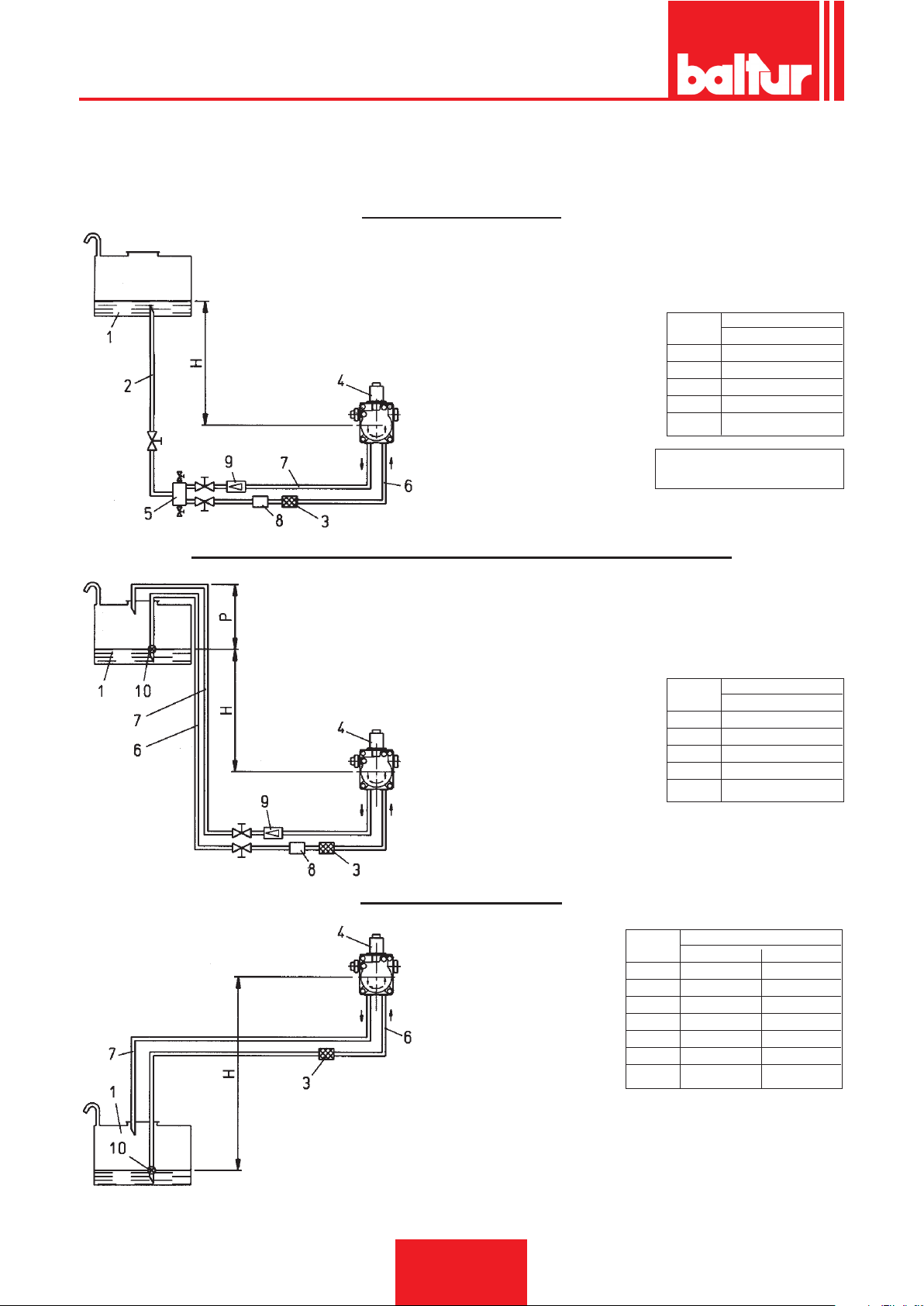
ENGLISH
TABLE OF PIPELINE FOR BT 40 - 55 - 75 - 100 DSN - 4T
WITH FUEL AT 5° AT 50° C (40° AT THE 5° C PUMPING TEMPERATURE)
GRAVITY FEED SYSTEM
1 Tank
2 Feeding pipe
3 Wire-net lter
4 Pump
5 Degasier
6 Suction pipe
7 Return pipe
8 Automatic fuel interception
device at burner shut off
9 Non-return valve
Pump axis
H Total length
meters meters
Ø = 1"
1 31
2 35
2,5 35
3 35
Maximum intake and return
pressure = 1 bar
SIPHON FEED SYSTEM WITH FEED FROM THE TOP OF THE TANK
1 Tank
3 Wire-net lter
4 Pump
6 Suction pipe
Pump axis
7 Return pipe
8 Automatic fuel interception
device at burner shut off
9 One-way valve
10 Bottom valve
H Total length
meters meters
Ø = 1"
1 31
2 35
2,5 35
3 35
Maximum intake and return
pressure = 1 bar
Dimension P = 3,5 m. (max.)
SUCTION FEED SYSTEM
Pump axis
1 Tank
3 Wire-net lter
4 Pump
6 Suction pipe
7 Return pipe
10 Bottom valve
H Total length meters
meters Ø = 1" Ø 1" 1/4
0,5 22 35
1 17 35
1,5 12 35
2 7 21
2,5 3 8
3 - 3,5 - -
N.B. Comply with existing regulations regarding apparatus required in
the pipeline system
H - Height difference between minimum fuel tank level and pump axis.
L - Total length of pipeline, including vertical lenght. Subtract 0,25 mt.
for every elbow or gate valve.
12 / 38
0006080547_201610
Page 55
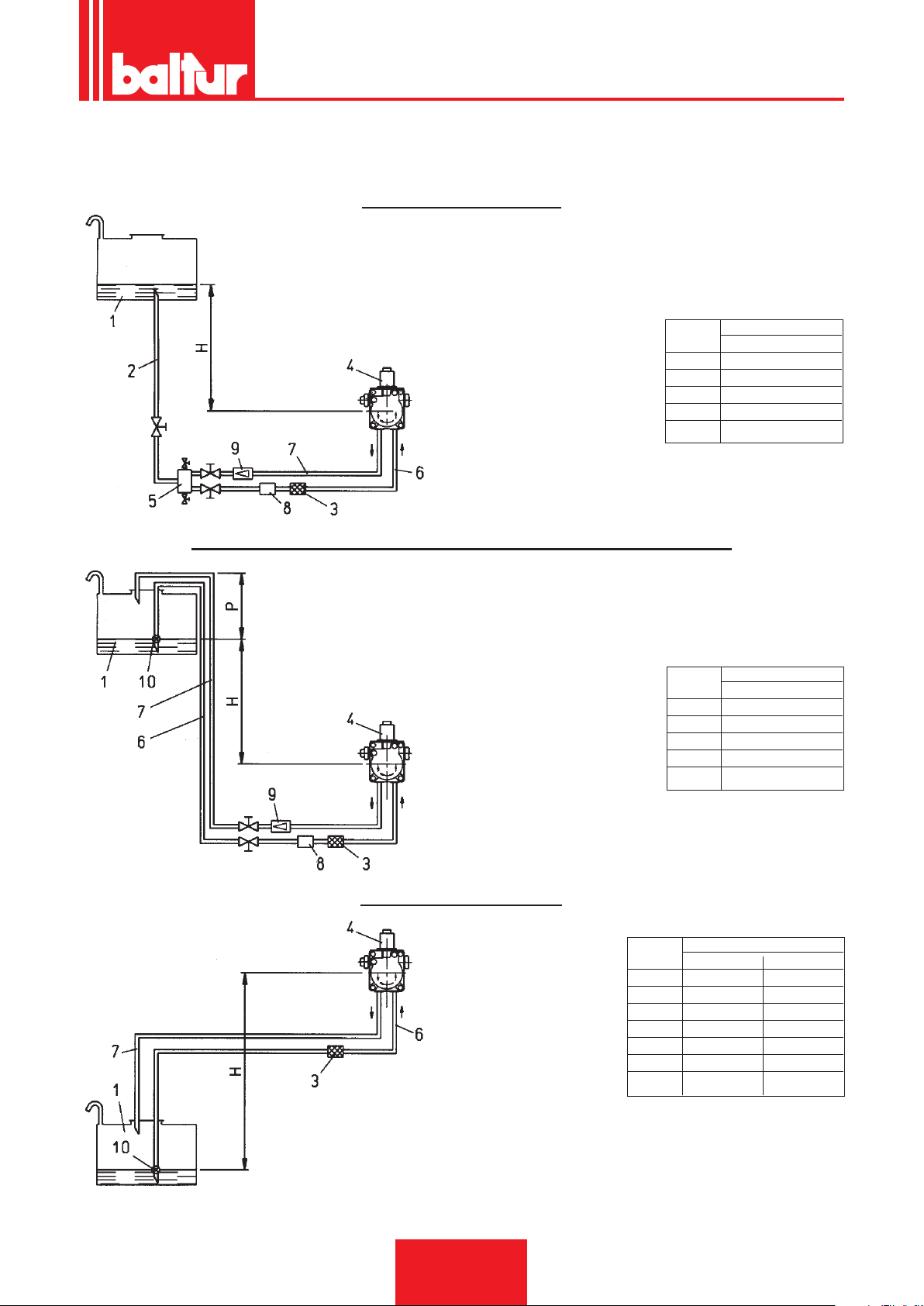
TABLE OF PIPELINE FOR BT 120 DSN - 4T
WITH FUEL AT 5° AT 50° C (40° AT THE 5° C PUMPING TEMPERATURE)
GRAVITY FEED SYSTEM
1 Tank
2 Feeding pipe
3 Wire-net lter
4 Pump
5 Degasier
6 Suction pipe
7 Return pipe
8 Automatic fuel interception
device at burner shut off
9 Non-return valve
Pump axis
Maximum intake and return pressure = 1 bar
H Total length
meters meters
Ø = 1" 1/4
1 45
1,5 45
2 50
2,5 50
ENGLISH
SIPHON FEED SYSTEM WITH FEED FROM THE TOP OF THE TANK
1 Tank
3 Wire-net lter
4 Pump
6 Suction pipe
Pump axis
7 Return pipe
8 Automatic fuel interception
device at burner shut off
9 One-way valve
10 Bottom valve
Maximum intake and return pressure = 1 bar
Dimension P = 3,5 m. (max.)
H Total length
meters meters
Ø = 1" 1/4
1 45
1,5 45
2 50
2,5 50
SUCTION FEED SYSTEM
Pump axis
1 Tank
3 Wire-net lter
4 Pump
6 Suction pipe
7 Return pipe
10 Bottom valve
H Total length meters
meters Ø = 1" 1/4 Ø 1" 1/2
0,5 35 40
1 30 35
1,5 26 35
2 13 25
2,5 5 10
3 - 3,5 - -
N.B. Comply with existing regulations regarding apparatus required in the pipeline system
H - Height difference between minimum fuel tank level and pump axis.
L - Total length of pipeline, including vertical lenght. Subtract 0,25 mt.
for every elbow or gate valve.
13 / 38
0006080547_201610
Page 56
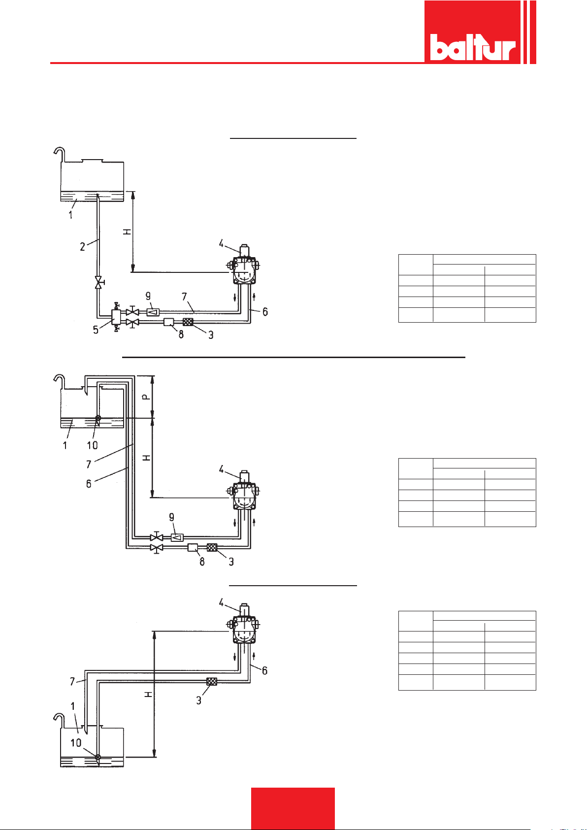
ENGLISH
TABLE OF PIPELINE FOR BT 180 DSN - BT 250 DSN
WITH FUEL AT 5° AT 50° C (40° AT THE 5° C PUMPING TEMPERATURE)
GRAVITY FEED SYSTEM
1 Tank
2 Feeding pipe
3 Wire-net lter
4 Pump
5 Degasier
6 Suction pipe
7 Return pipe
8 Automatic fuel interception
device at burner shut off
9 Non-return valve
Pump axis
H Total length meters
meters Ø = 1" 1/2 Øi. 41 mm
1 35 35
1,5 40 40
2 50 50
2,5 50 50
SIPHON FEED SYSTEM WITH FEED FROM THE TOP OF THE TANK
1 Tank
3 Wire-net lter
4 Pump
6 Suction pipe
7 Return pipe
8 Automatic fuel interception
device at burner shut off
H Total length meters
meters Ø = 1" 1/2 Øi. 41 mm
1 35 35
1,5 40 40
2 50 50
2,5 50 50
Dimension P = 3,5 m. (max.)
Pump axis
9 One-way valve
10 Bottom valve
SUCTION FEED SYSTEM
Pump axis
1 Tank
3 Wire-net lter
4 Pump
6 Suction pipe
7 Return pipe
10 Bottom valve
H Total length meters
meters Ø = 1" 1/2 Øi. 41 mm
0,5 25 25
1 20 20
1,5 15 15
2 10 10
2,5 5 5
N.B. Comply with existing regulations regarding apparatus required in
the pipeline system
H - Height difference between minimum fuel tank level and pump axis.
L - Total length of pipeline, including vertical lenght. Subtract 0,25 mt.
for every elbow or gate valve.
14 / 38
0006080547_201610
Page 57
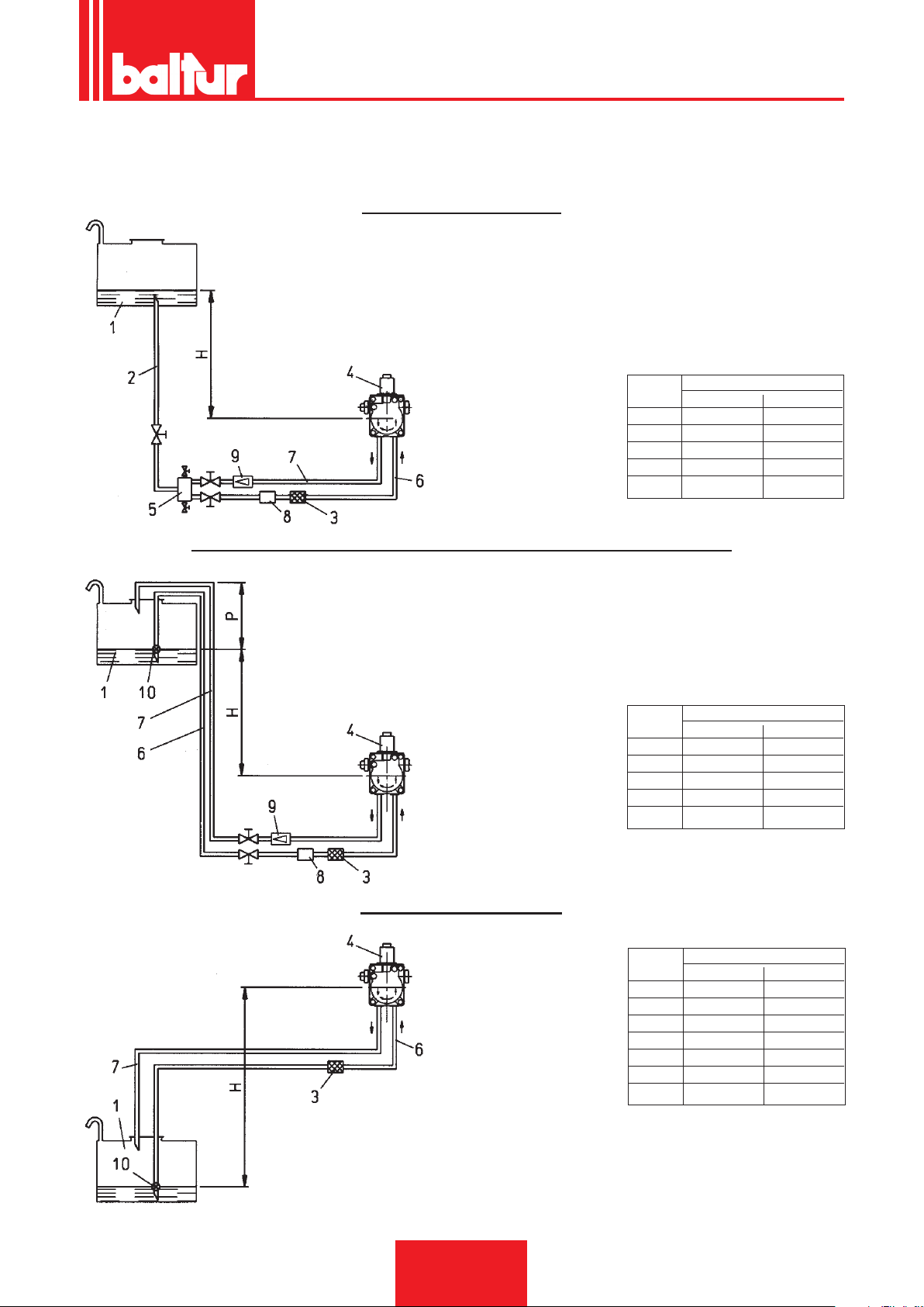
TABLE OF PIPELINE FOR BT 300 DSN - BT 350 DSN
WITH FUEL AT 5° AT 50° C (40° AT THE 5° C PUMPING TEMPERATURE)
GRAVITY FEED SYSTEM
1 Tank
2 Feeding pipe
3 Wire-net lter
4 Pump
5 Degasier
6 Suction pipe
7 Return pipe
8 Automatic fuel interception
device at burner shut off
9 Non-return valve
Pump axis
H Total length meters
meters Ø = 1" 1/2 Øi. 41 mm
1 30 30
1,5 35 35
2 40 40
2,5 45 45
3 50 50
ENGLISH
SIPHON FEED SYSTEM WITH FEED FROM THE TOP OF THE TANK
1 Tank
3 Wire-net lter
4 Pump
6 Suction pipe
7 Return pipe
8 Automatic fuel interception device at burner shut off
9 One-way valve
10 Bottom valve
Pump axis
H Total length meters
meters Ø = 1" 1/2 Øi. 41 mm
1 30 30
1,5 35 35
2 40 40
2,5 45 45
3 50 50
Dimension P = 3,5 m. (max.)
SUCTION FEED SYSTEM
Pump axis
1 Tank
3 Wire-net lter
4 Pump
6 Suction pipe
7 Return pipe
10 Bottom valve
H Total length meters
meters Ø = 1" 1/2 Øi. 41 mm
0,5 25 25
1 20 20
1,5 15 15
2 8 8
2,5 3 3
3 – –
3,5 – –
N.B. Comply with existing regulations regarding apparatus required in
the pipeline system
H - Height difference between minimum fuel tank level and pump axis.
L - Total length of pipeline, including vertical lenght. Subtract 0,25 mt.
for every elbow or gate valve.
15 / 38
0006080547_201610
Page 58

ENGLISH
VISCOSITY - TEMPERATURE CHART
AUXILIARY PUMP (SEE BT 8511/6 AND BT 8513/7)
In some cases (excessive horizontal distance, vertical distance or high viscosity and always when using the burners in the dense “D” version) it is necessary to t the unit with a “loop” feed system using an auxiliary pump, thus
avoiding direct connection of the burner pump to the tank.
In this case the auxiliary pump can be started as a function of burner start-up and stopped when the burner
stops.
Carry out auxiliary pump electrical connections by connecting the coil (230 V) which controls the pump relay
switch to the “N” terminals (control box input terminal block) and “L1” terminals (downstream from the motor relay
switch).
Always observe the following:
- the auxiliary pump must be installed as close as possible to the liquid to be sucked.
- the head must be adequate for the system in question.
- a ow-rate at least equal to burner pump ow-rate is recommended.
- connection piping must be sized as a function of auxiliary pump ow-rate.
- Never electrically connect the auxiliary pump directly to the burner motor relay switch.
16 / 38
0006080547_201610
Page 59
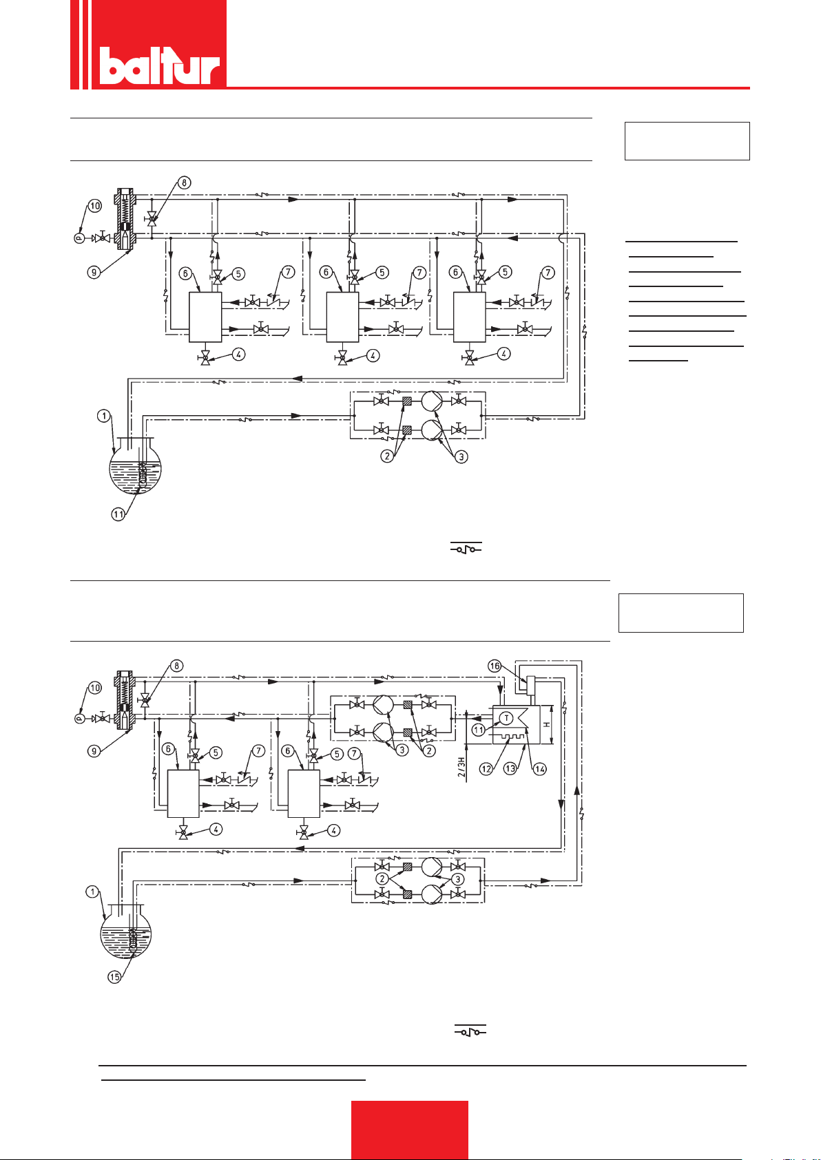
ENGLISH
BASIC HYDRAULIC DIAGRAM FOR MULTIPLE TWO-FLAME OR
MODULATING BURNERS USING FUEL OIL (MAX 15 °E AT 50 °C)
1 - MAIN TANK
2 - FILTER
3 - CIRCULATION PUMP
4 - WATER AND SYSTEM DISCHARGE
5 - NORMALLY CLOSED AIR-GAS DISCHARGE
6 - FUEL RECOVERY TANK AND DEGASSING UNIT
7 - NON-RETURN VALVE
6 - BY PASS (NORMALLY CLOSED)
9 - ADJUSTABLE PRESSURE REGULATOR, 0.5 - 2 BAR
10 - PRESSURE GAUGE (0-4 BAR)
11 - HEAVY OIL HEATING COIL, STEAM OR HOT WATER
HEATING ELECTRICAL LEAD (IF NECESSARY)
N° BT 8511/6
N.B. The thank for reco-
very of hot oil
(diameter 150 mm,
height 400 mm)
should be installed
as near as possible
to the burner and
about 0.5 m, above
the pump.
BASIC HYDRAULIC DIAGRAM FOR MULTIPLE TWO-FLAME OR
MODULATING BURNERS FUNCTIONING WITH DENSE FUEL OIL
(MAX 50 °E AT 50 °C) AND AUXILIARY HEATER
1 - MAIN TANK
2 - FILTER
3 - CIRCULATION PUMP
4 - WATER AND SYSTEM DISCHARGE
5 - NORMALLY CLOSED AIR-GAS DISCHARGE
6 - FUEL RECOVERY TANK AND DEGASSING UNIT
7 - NON-RETURN VALVE
6 - BY PASS (NORMALLY CLOSED)
9 - ADJUSTABLE PRESSURE REGULATOR, 0.5 - 2 BAR
10 - PRESSURE GAUGE (0-4 BAR)
11 - THERMOMETER
12 - ELEMENT
13 - AUXILIARY HEATER
14 - STEAM COIL OR HOT WATER TO HEAT THE OIL
15 - HEAVY OIL HEATING COIL, STEAM OR HOT WATER
16 - HUB DIAMETER 100MM, HEIGHT 300MM
HEATING ELECTRICAL LEAD (IF NECESSARY)
N° BT 8513/7
N.B. The thank for recovery of hot oil (diameter 150 mm, height 400 mm) should be installed as near as possible to
the burner and about 0.5 m, above the pump.
17 / 38
0006080547_201610
Page 60

ENGLISH
INITIAL PIPING FILL
After checking that the protective plastic plugs placed inside the pump couplings have been removed, proceed as follows:
1) Turn the switch on the burner to “O”.
This prevents automatic ignition of the burner and, in particular, prevents the heating elements being switched
on, components which, if left on with the tank empty could burn out.
2) Make sure, if the burner is three-phase, that the motor turns anticlockwise (when looking at the
burner from the pump side). Direction of rotation can be ascertained by observing the direction of fan
rotation via the spy-hole on the rear end of the worm screw. To start the motor close the relay switch
manually (by pressing on the mobile part) for a few seconds and observe which way the fan turns.
Should it be necessary to invert rotation switch over two phases on the power line input terminals (L1-L2 -L3).
Note: To be sure which way the fan is rotating wait for it to slow down as it may otherwise give the onlooker
a false impression.
3) Remove (if already connected) the exible hoses from the aspiration and return piping.
4) Immerge the end of the exible suction hose in a recipient containing lubricating oil or fuel oil (do not use low-
viscosity products such as light oil, petrol, kerosene etc).
5) Now press the mobile part of the motor relay switch to start the motor and therefore the pump.
Wait until the pump has aspirated a quantity of lubricant equivalent to about 1 or 2 cups, then stop.
This operation serves to avoid the pump working on empty conditions and to increase suction capacity.
N.B. Pumps operating at 2800 rpm MUST NEVER run on empty as they will quickly seize.
6) Now connect the hose to the suction pipe and open all its dampers and all other fuel interception devices.
7) Now press the mobile part of the relay switch once again to start the pump; this will draw the fuel from the
tank.
Note: Where piping is long it may be necessary to release air via the vent plug. If the pump is not equipped
with such a plug remove the pressure gauge attachment plug. In this case, when the fuel is seen to
ow out of the pressure gauge coupling hole stop and replace the plug. Then continue lling until the
tank is full (the preheating tank is full when fuel is seen to ow out of the return hose which has not yet
been connected).
8) Connect the return hose to the piping and open the gates situated on this pipe. The burner is now ready for
ignition.
DESCRIPTION OF OPERATION
NOTE: The “D” (dense) version burners are equipped with an auxiliary element for the pump, the atomization unit
and for the two solenoid valves. In addition, the line lter is preheated.
By closing the switch on the burner the heating elements relay switch is turned to ON (if the relative thermostat
so allows). Voltage arrives at the elements relay switch via the regulating thermostat contact. Once the heating
elements have been switched on they heat the fuel oil in the preheating tank. When the fuel oil temperature reaches
a certain point the minimum thermostat goes off. When the latter is off (and if the other regulation and safety
thermostats provide consensus) the current will arrive at the control box which switches on the burner devices as
per the preset program. The ignition transformer is switched on at the same time as the burner motor (with the OR
3/B control box). However, with the LAL 1.25 control box the transformer is switched on a few seconds later. The
motor turns the fan which preventilates the combustion chamber with air and simultaneously drives the pump which
circulates the hot oil through the ducts and expels the cold oil and any gas (via the return). This “preventilation”
stage terminates when solenoid valve n° 7 closes (open in its home position), interrupting oil discharge towards
the tank. Solenoid valve closure is followed by an increase of pressure in the delivery pipes.
NOTE: The preheater net lter incorporates an “anti-gas” spring valve which opens and allows fuel to ow only
on attainment of a pressure of 2 - 2.5 bar. The purpose of this valve is to keep the preheater under
slight pressure even with the burner off so as to reduce, and preferably avoid, gas formation with the
oil hot and the burner off. As the pressure loss caused by this “anti-gas” valve is about 2 - 2.5 bar it
is therefore necessary to raise atomization pressure (pump pressure) in order to compensate for that
loss. In practice it will be necessary to adjust pump pressure to 27 bars. When this pressure reaches
16 bars the nozzle n° 4 closure device in the atomization unit opens; this allows the oil to reach the
nozzle of the 1st stage and from here to enter the combustion chamber in a nely atomized state.
Pressure stabilizes at around 27 bars because the pump pressure regulator is set at this value.
18 / 38
0006080547_201610
Page 61

ENGLISH
As soon as the atomized oil leaves the nozzle it is ignited by the spark from the electrodes. During
1st stage ignition the servomotor keeps the air ap in a set position according to the quantity of
fuel burnt. If a ame is ignited properly the shutdown position is passed, the ignition transformer is
switched off and the 2nd stage n° 8 solenoid valve is switched on (closed in the home position).
Opening of the 2nd stage valve allows the fuel (at a pressure of 25 bars) to reach the closure device of the
2nd stage nozzle (n° 4/1).
nd
The pressure of 25 bars (27 - 2 = 25) acts on the nozzle closure device of the 2
stage which, up to a
pressure of 16 bars, stops fuel owing to the second nozzle. This device is thus opened by the pressure
itself and the second nozzle starts working. A pressure of 25 bars now acts on the two nozzles. To read
off the effective pressure at the atomization unit and thus at the nozzles we recommend that you connect
the pressure gauge to the tank lter coupling (see drawing 0002932230).
NOTE: It is evident from the above that the choice of nozzles, as a function of total desired ow-rate (2 nozzles
working), must be made by taking into account the ow-rates corresponding to a working pressure of 25
bars. However, it is necessary to bear in mind that when the burner is working with the rst stage only the
fuel supply rate is that which corresponds to one nozzle only as a function of 25 bars pressure.
It is obviously possible to vary the “relationship” between the rst and the second stage extensively by
changing the nozzles. To ensure proper operation, always bear in mind that the fuel supply rate with the
rst stage must never be less than the model-specic minimum ow-rate (see identication plate).
A lower ow-rate could make ignition difcult and combustion with the rst stage only may not be good.
NOTE: Some burner models have three nozzles (see drawing n° 0002900564). In this case there are two second
stage nozzles and both are subject to a pressure of 25 bars.
From the moment in which the ame appears in the combustion chamber the burner is controlled by the photo-
resistance and the thermostats. When the temperature or pressure reaches the levels set on the thermostat or
working pressure switch that device will shut down the burner. The unit resumes normal operation automatically
when the temperature/pressure falls by the necessary amount.
If, for any reason, the ame goes out while the unit is working a (second) photoresistance cuts power to the power
relay switch and opens it; this switches off the n° 7 preventilation solenoid valve which opens and rapidly vents
the existing pressure. The atomized oil spray is intercepted by automatic closure of the nozzle shutdown devices
on the atomizing unit as soon as pressure falls below their settings.
In this case (with OR 3/B control box) the ignition stage is automatically repeated and, if the rst stage is lit normally,
the burner starts working again normally too. If this is not the case (irregular or absent ame) the unit shuts down
automatically. With the LAL 1.25 control box an absent ame causes the burner to shut down without “attempting”
a second ignition. If the program is interrupted (power failure, manual work, tripped thermostat etc.) during the
preventilation stage the programmer goes to its home position and repeats the entire burner ignition sequence.
CONTROL BOX SPECIFICATIONS
Burner Control box and Safety time Preventilation time Post-ignition Time between 1st
Model relative programmer in seconds in seconds in seconds and 2nd stage
in seconds
BT 40 DSN - 4T
BT 55 DSN - 4T OR 3/B 5 30 5 5
BT 75 DSN - 4T
BT 100 DSN - 4T
BT 120 DSN - 4T
BT 180 DSN - 4T LAL 1.25
BT 250 DSN - 4T 5 22,5 15 7,5
BT 300 DSN - 4T Cyclical relay
BT 350 DSN - 4T
19 / 38
0006080547_201610
Page 62

ENGLISH
IGNITION AND ADJUSTMENT
Before igniting make sure that:
a) Connections with the fuel line, thermostats or pressure switches are carried out exactly as illustrated in the
control box wiring diagram.
b) There is fuel in the tank and water in the boiler.
c) That all the sluice valves on the fuel oil suction and return piping are open as is every other part through which
the fuel ows.
d) Combustion fumes discharge occurs freely (boiler ue gates and chimney open).
e) Make sure the burner head penetrates the combustion chamber in accordance with the boiler manufacturer’s
specications. To ensure this is so the burner is equipped with a boiler attachment ange which slides with
respect to the combustion head.
f) The burner nozzles are compatible with boiler output; if necessary, replace them.
The quantity of fuel being delivered must never be greater than the maximum boiler-requested quantities or
maximum admissible burner quantities. Bear in mind that the combustion head has been designed for use
with nozzles having a 45° spray angle.
Note: To ensure good ignition and combustion with the rst stage only, fuel delivery must not be notably lower
than the minimum ow-rate for the employed burner (see identication plate).
FOR IGNITION PROCEED AS FOLLOWS:
Note: The burner is equipped with a manual switch to change from the 1st to the 2nd stage.
1) Switch on the 1st and 2nd stage switch to prevent ignition of the 2nd ame.
2) Slightly open the air gate to obtain the air-ow thought necessary for burner operation with the 1st stage
by acting on the cam which limits the servomotor stroke for the 1st stage (see BT 8653/1 or BT 8711/1).
Adjust the air adjustment device on the combustion head to an intermediate position (see, further on, “Air
regulation on the combustion head”).
3) Turn on the main switch and the ON/OFF burner switch.
This switches on all the fuel oil heating elements and simultaneously causes the yellow warning light on the
burner to come on.
4) The minimum thermostat comes on when the fuel contained in the preheater reaches the set temperature.
When the minimum thermostat switches off the control box (if the other boiler thermostats are off) is switched
on; the control box then switches on the devices making up the burner as per the pre-set program.
The unit ignites as illustrated in “Description of Operation”.
5) When the burner is operating with the 1st stage adjust, as described in point 2, the air quantity so that good
combustion is ensured. It is better to have a slightly poor 1st stage air-ow in order t ensure perfect ignition
even under the most demanding conditions.
6) After regulating the 1st stage air-ow stop the burner by cutting power at the main switch. Connect the terminals
of the 2nd stage thermostat terminal block together and position the1st-2nd stage switch to 2nd stage.
7) Act on the cam which limits the 2nd stage air gate servomotor stroke; adjust to the quantity thought necessary
for the fuel to be burnt (see BT 8653/1 or BT 8711/1).
8) Switch the unit back on; it will now pass automatically to the second stage according to the set program.
9) With the unit now operating with the 2
ow to the quantity needed to ensure good combustion. Combustion checks should be carried out with special
instruments. If suitable instruments are unavailable observe the colour of the ame. We recommend that you
adjust to obtain a soft, light orange ame: avoid a red ame that gives off smoke or a white ame with excess
air. The air regulator must be in a position which gives a percentage of carbon dioxide (CO2) in the fumes that
varies from a minimum of 10% to a maximum of 13% with a smoke rating that does not exceed standard limits
(Bacharach scale). We recommend that you adjust to obtain a soft, light orange ame: avoid a red ame that
gives off smoke or a white am with excess air (see also “Air adjustment on the combustion head”.
10) Adjustment of the preheater thermostats, minimum thermostat and regulation thermostat (max) is effected
by the manufacturer and set at values which may, however, be unacceptable in certain individual cases. It is
therefore necessary, during nal testing, to check that these values do not cause problems (poor combustion,
smoke, formation of gas in the preheater, etc.). Where necessary, increase or decrease the settings; bear in
mind that the regulation thermostat must nevertheless be at a temperature approximately 15° higher than the
minimum thermostat setting. The minimum thermostat must close at the minimum temperature needed to ensure
that fuel arrives at the nozzle with viscosity below 2° E. This condition is indispensable for proper atomization.
(As a rough guide see the viscosity-temperature diagram regarding the employed oil type).
nd
stage, adjust (by operating on the cam described in point 7) the air-
20 / 38
0006080547_201610
Page 63

ENGLISH
ADJUSTING THE AIR ON THE COMBUSTION HEAD
The combustion head is equipped with a regulation device that restricts (moves forwards) or opens up (moves
backwards) the air ow between the diffuser disc and the head. Closing the passageway therefore generates high
pressure upstream from the diffuser disc even at low ow-rates Being at high speed and somewhat turbulent, the
air penetrates the fuel better, giving an excellent mix and good ame stability.
High air pressure upstream from the diffuser disc may be necessary to prevent ame pulsation; this condition is
practically essential when the burner is working on a pressurized chamber and/or at high thermal loads.
It is clear from the above description that the device which closes off the air in the combustion head must be
brought into a position which always gives decidedly higher air pressure behind the diffuser disc.
It is recommended that adjustment be carried out to provide on-head air closure that requires considerable opening
of the air gate which adjusts the burner fan intake ow; this condition must, of course, be obtained when the burner
is working at maximum desired fuel ow-rates. In practice adjustment must be begun with the on-head air closure
device in an intermediate position and by igniting the burner for approximate regulation as described previously.
When maximum desired fuel ow rates are reached correct the position of the device which closes off combustion
head air: do this by shifting forwards or backwards so that an air ow compatible with fuel ow is obtained with
the air intake ap wide open. When restricting air ow on the combustion head avoid complete closure. Check for
perfect centering with respect to the diffuser disc. Please note that imperfect centering with respect to the diffuser
disc may lead to poor combustion and excessive heating of the head with consequent rapid deterioration. Check
by looking through the spy-hole on the rear part of the burner and then tightening (all the way) the screws that
hold the combustion head air regulation device in position.
N.B. Check that ignition occurs properly:
if the regulator has shifted forwards the high speed of the outgoing air may make ignition difcult.
Should such a situation occur shift the regulator back a little at a time until it is in a position that gives regular
ignition and take this as the denitive setting.
It should be pointed out, once again, that for the 1st stage it is preferable to limit the air quantity to an indispensable
minimum so as to ensure secure ignition even under the most difcult conditions.
ADJUSTING THE DISTANCE BETWEEN THE DIFFUSER DISC AND THE NOZZLE
The burners are equipped with a device that allows adjustment of the distance between the diffuser disc and the
nozzle. The distance between diffuser disc and nozzle is set by the manufacturer and must only be reduced if it
is noted that the atomized fuel cone exiting the nozzle wets the diffuser disc and consequently stains it.
CHECKS
Once the burner is operating check the safety devices (photoresistance, shutdown, thermostats).
1) The photoresistance is the ame control device. It must therefore cut in if, during operation, the ame goes
out (carry out this check at least 1 minute after ame ignition).
2) The burner must shut itself down and stay off when, during ignition and within the control set time, the ame
fails to appear. Shutdown immediately cuts fuel ow, stops the motor and therefore the burner and causes
the shutdown warning light to come on. To check photoresistance efciency proceed as follows:
a) start the burner.
b) at least 1 minute after ignition extract the photoresistance by removing it from its housing and simulate a
“no ame” situation by covering the photoresistance (obscure the photoresistance support window with a
rag). The ame should go out (with control box LAL 1.25 the burner shuts down).
c) If, with control box OR 3/B, the photoresistance is kept in the dark the burner re-ignites but the photoresi-
stance does not “see” the light and the burner shuts down in a time determined by program settings. The
burner can only be reset by pressing the appropriate push-button.
3) To check thermostat efciency run the burner until the water in the boiler reaches a temperature of at least 50° C
and then act on the thermostat control knob, lowering the temperature setting until the “click” of the opening
switch is heard and simultaneous burner shutdown is observed. The thermostat must trip within a maximum
“lag” of 5 - 10° C with respect to the control thermostat (boiler thermometer). If this is not so modify the thermostat scale calibration so that it corresponds with thermometer settings.
21 / 38
0006080547_201610
Page 64

ENGLISH
USING THE BURNER
The burner operates on a fully automatic basis. Turning on the main switch and control panel switch turns the
burner ON. Burner operation is governed by the controls described in “Description of Operation”.
The “shutdown” position is a safety position to which the burner sets itself automatically when some burner or
system components is operating improperly. It is therefore good practice to make sure that there are no anomalies
before “resetting” the burner. The burner can stay in the shutdown position indenitely.
Shutdowns may be caused by transitory faults (a little water in the fuel, air bubbles in the piping etc.). In such cases
the burner restarts easily when reset. When, however, shutdowns occur repeatedly (3 - 4 times) do not attempt
any more restarts; check there is fuel in the tank and contact the local After-Sale Service to have the fault dealt
with properly. To reset the unit press the appropriate push-button.
MAINTENANCE
The burner requires no special maintenance. It is, however, good practice, at least at the end of the heating
season, to carry out the following tasks:
1) Remove and wash the filters, the nozzle, the diffuser disc and the ignition electrodes with solvents
(petrol, trichlorethylene, naphta). Do not use metallic objects to clean the nozzle (use wood or plastic).
2) Clean the photoresistances.
3) Have the boiler cleaned and, if necessary, the ue.
N.B. The nozzle (or nozzles) must be replaced at least every two heating seasons. This may be necessary even
more frequently.
TWO-STAGE BURNERS: DESCRIPTION OF OPERATION
The two-stage burner always ignites with reduced fuel and air ow-rates (1st stage) and then, after a few seconds,
runs in full air and fuel ow work mode (2nd stage). Second stage ignition requires consensus from the control
box and control device (pressure switch and thermostat).
When running at full ow the unit will remain in this mode until pressure or temperature reaches control device
(pressure switch or thermostat) settings. The control device trips and extinguishes the second stage (fuel and air)
when its setting levels are reached. The burner then continues to operate with the rst stage only.
The rst stage is, on its own, not normally sufcient to maintain pressure or temperature at desired levels.
Therefore the latter falls until it reaches the level at which the second stage control device (pressure switch or
thermostat) restores total fuel and air ow-rates. The burner is shut down completely when, with only the rst stage
burning, pressure or temperature reaches a level that trips the operating device (pressure switch or thermostat).
The unit re-ignites automatically when pressure or temperature falls below the levels to which the pressure switch
or thermostat has been set.
N.B. It is usually inadvisable to connect up a burner for two-stage operation when used on a boiler that produces
hot water for heating purposes. In this case the burner works (sometimes for extensive periods) on a single
stage only and the boiler is insufciently heated; consequently combustion fumes exit at a too low temperature (less than 180° C), giving rise to soot at the ue. When the boiler is insufciently lled the formation of
acid condensate and soot in the boiler becomes highly probable, leading to rapid clogging and corrosion of
the boiler itself. When the two-stage burner is installed on a boiler providing hot water for heating purposes
it must be connected so that it gives full-ow operation with both stages and complete shutdown (without
passing over to single-stage operation) on attainment of set temperature. To obtain this operating mode
the second stage thermostat is not installed and a direct “jumper” connection (bridge) is effected between
the respective control box terminals. This solutions means that only the burner’s ability to ignite at low owrates (smooth ignition) is employed; this condition is indispensable for boilers with pressurized combustion
chambers yet is also useful with standard boilers (negative pressure combustion chamber). Burner control
(ignition or shutdown) is subordinate to the usual working or safety thermostats.
22 / 38
0006080547_201610
Page 65

ENGLISH
INSTRUCTIONS FOR TROUBLE - SHOOTING AND REPAIRING OPERATING PROBLEMS
WITH HEAVY OIL BURNERS
PROBLEM
The appliance goes into block with
ame on (red light on).
Breakdown limited to the ame moni-
toring device.
The appliance goes into block, spraying
fuel, without igniting any ame (red
light on).
The breakdown is limited to the ignition
device, with the condition that fuel
is in good shape (not polluted with
water or other), is properly preheated
(when burning fuel oil) and is correctly
atomized.
The appliance goes into block, spraying
fuel, wothout igniting any ame (red
light on).
POSSIBLE CAUSE
1) Photoresistance dirty with soot, or broken
2) Insufcient draft
3) Photoresistance circuit interrupted
4) Dirty disk or orice
1) Ignition dirty with soot, or broken
2) The ignition transformer cables are earthed
3) Ignition transformer cables are not well
connected
4) Ignition transformer shorted
5) Tips of electrodes are not at a proper
distance
6) Electrodes discharge to ground because
they are dirty or have broken insulation; also
check below insulation clamp terminals
1) Uneven pump pressure
2) Water in the fuel
3) Insufcient preheating of fuel oil
4) Excess combustion - supporting air
5) Air passage between disk and orice too
closed down
6) Worn or dirty nozzle
REMEDY
1) Clean or replace
2) Check all fume passages in the boiler and
in the chimney
3) Replace the appliance
4) Clean
1) Check the entire circuit
2) Replace
3) Clamp them
4) Replace
5) Put them in the proper positions
6) Clean or, if necessary, replace
1) Regulate pump
2) Drain from preheating tank and mesh lter
trough the plugs provided. If necessary
drain from the fuel tank using a suitable
pump (never use the burner pump to do
this)
3) Increase preheating
4) Reduce combustion - supporting air
5) Correct position of the combustion head
regulation device
6) Clean or replace
The appliance goes into clock without
spraiyng fuel (red light on).
Nois burner pump
1) One phase is missing
2) Broken electric motor
3) Fuel oil not reaching pump
4) No fuel oil in the fuel tank
5) Intake pipeline gate valve closed
6) Nozzle clogged
7) Motor (three-phase) rotating in the opposite
direction to that indicated by the arrow
8) Bottom valve leaks or is blocked
9) Defective pump
10)Formation of steam or gas in the preheater,
causing it to ll up slowly. (in this case the
pressure gauge will only slowly reach the
preset operating pressure value; too late
with respect to the maximum time permitted
by the programmer)
11)Preheater tank lter clogged
12)Broken solenoid valve
13)Atomizing group valve does not open
14)Voltage too low
1) Fuel oil in the tank too viscous
2) Pipeline diameters too small
3) Air entering into the pipelines
4) Dirty lter
5) Too great a distance between tank and
burner, or meny accidental load lossen (curves, elbows, pinches, etc.)
6) Worn hoses
7) Fuel oil too viscous in some part of the
intake pipeline
1) Check supply lines
2) Repair or replace
3) Check intake pipeline
4) Fill fuel tank
5) Open
6) Remove and throughly clean
7) Invert one supply phase
8) Dismantle and clean
9) Replace
10)Loosen the preheater tank plug a few turns
and discharge any water. If fuel comes
out instead of water it is likely that the gas
produced inside the preheater comes from
the evaporation of fuel; Therefore regulate
the temperature on the control thermostat,
lowering it to below 100 °C. Also check
the inclination of the tank as described in
the chapter "Application of the burner to
the boiler"
11)Dismantle and clean
12) Check and, if necessary, replace
13)First check that fuel is at the proper
pressure, then, if necessary, replace the
atomizing group
14)Enquire of the electric company
1) Preheat in the tank or replace with a more
uid oil
2) Replace pipelines, in accordance with
installation instructions
3) Find and eliminate any inltrations
4) Dismantle and clean
5) Straighten out the path travelled by the
intake pipeline, reducing the distance
6) Replace hoses
7) Properly insulate the pipeline
23 / 38
0006080547_201610
Page 66

ENGLISH
PROBLEM
Fuel oil heats up too slowly, or doesn't
heat up at all.
Burner does not start when the minimum preheating temperature for the
fuel oil is reached.
Burner does not start
Poor ame, with sparks
Poorly shaped ame with smoke and
soot
POSSIBLE CAUSE
1) Mains voltage too low
2) One or more heating coils burned out
3) Defective or mistaken electrical connections
4) Total heating coil power lower than nozzle
capacity requirements
1) Thermostats (boiler or room) or pressure
switches are open
2) Short - circuit photoresistance
1) No current, either main switch is open, or
meter circuit breaker open or mains failure
2) Thermostat line is not made according to
the diagram, or a thermostat is open
3) Breakdown inside the appliance
1) Fuel oil too cold
2) Atomozing pressure too low
3) Excess combustion - supporting air
4) Dirty or worn nozzle
5) Water in the fuel
1) Insufcient combustion - supporting air
2) Dirty or worn nozzle
3) Combustion chambre too small or of
unsuitable shape
4) Nozzle capacity too low with respect to
combustion chamber volume
5) Fuel oil temperature too low
6) Unsuitable or excessive refractory lining
7) Clogged chimney or boiler ducts
8) Low atomizing pressure
REMEDY
1) Speak with the electric Company
2) Replace
3) Check
4) Decrease ow rate, insofar as is possible
with the plant's heating requirements
1) Raise their settings, or wait until pressure
or temperaturevalues naturally decrease
to close them
2) Replace
1) Close switches or wait until power returns
2) Check connections and thermostats
3) Replace
1) Increase temperature using the preheater
control thermostat
2) Reset at proper value
3) Reduce combustion - supporting air
4) Clean or replace
5) Drain water from the preheating tank and
the mesh lter through the drain plugs. Drain
water, if necessary, from the fuel tank as
well, using a suitable pump (never use the
burner pump to do this)
1) Increase combustion - supporting air
2) Clean or replace
3) Change the shape or decrease the capacity
of the nozzle in function of the combustion
chamber, or replace the boiler
4) Replace the nozzle, increasing its capacity
5) Increase
6) Modify or decrease, in accordance with
boiler manufacturer instructions
7) Clean
8) Raise pressure to the proper value
Defective ame, pulsanting or detaching from the combustion orice
Corrosion inside the boiler
Soot at the mouth of the chimney
1) Too much draft (only if there is a chimney
fan)
2) Preheating temperature unsuitable for the
type of fuel oil employed
3) Dirty or worn nozzle
4) Water in the fuel oil
5) Dirty disk
6) Excess combustion - supporting air
7) Air passage between disk and orice too
closed down
1) Boiler operating temperature too low (lower
than the dew point)
2) High percentage of sulphur in fuel oil
3) Fume temperature too low (below 180 °C)
1) Fumes cool down too much (below 180°C)
before reaching the stop, due to an insuf-
ficiently insulated exterior chimney or to
inltration of cold air
1) Modify pulley diametrs to change fan
speed
2) Increase or decrease
3) Clean or replace
4) Drain water from the preheating tank and
the mesh lter trough the drain plugs. Drain
water, if necessary, from the fuel tank as
well, using a suitable pump (never use the
burner pump to do this)
5) Clean
6) Reduce combustion - supporting air
7) Correct the position of the combustion head
regulation unit
1) Increase operating temperature
2) Change type of fuel oil
3) Replace nozzle, increasing nozzle capacity
1) Increase chimney insulation and eliminate
any openings where cold air can enter
24 / 38
0006080547_201610
Page 67
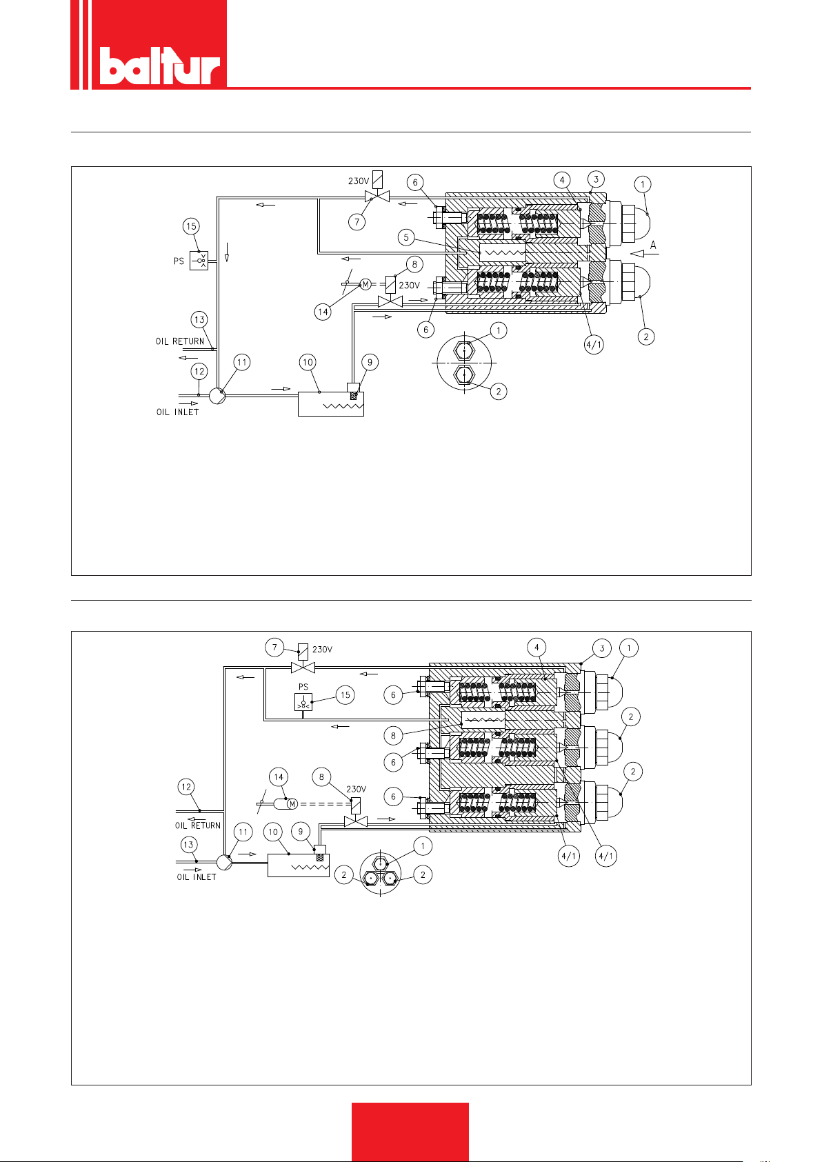
0002904640
0002900565
HYDRAULIC CIRCUIT SCHEMATIC DIAGRAM BT 40 - 55 - 75 - 100 - 120 - 180 DSN 4T
FRONT VIEW
1 1st stage nozzle
2 2nd stage nozzle
3 Spray nozzle unit support with adjustable closing device
4 1st stage nozzle closing device (calibrated at 16 bar)
4/1 2nd stage nozzle closing device (calibrated at 16 bar)
5 Heating element W 20 (version "D" only for high fuel viscosity)
6 Closing device adjustment screw
7 1st stage valve (normally open)
9 Self-cleaning filter 300 µ
10 Pre-heater
11 Pump (set at 27 bar)
12 Return
13 Intake
14 Air regulation servomotor
15 Oil max pressure swich 0 ÷ 16 bar (set to 5 bar)
8 2nd stage valve (normally closed)
ENGLISH
HYDRAULIC CIRCUIT SCHEMATIC DIAGRAM BT 250 - 300 - 350 DSN 4T
FRONT VIEW
1 1st stage nozzle
2 2nd stage nozzle
3 Spray nozzle unit support with adjustable closing device
4 1st stage nozzle closing device (calibrated at 16 bar)
4/1 2nd stage nozzle closing device (calibrated at 16 bar)
5 Heating element W 80 (thick version only)
6 Closing device adjustment screw
7 1st stage valve (normally open)
8 2nd stage valve (normally closed)
9 Self-cleaning filter 300 µ
10 Pre-heater
11 Pump (set at 27 bar)
12 Return
13 Intake
14 Air regulation servomotor
15 Oil max pressure swich 0 ÷ 16 bar (set to 5 bar)
25 / 38
0006080547_201610
Page 68
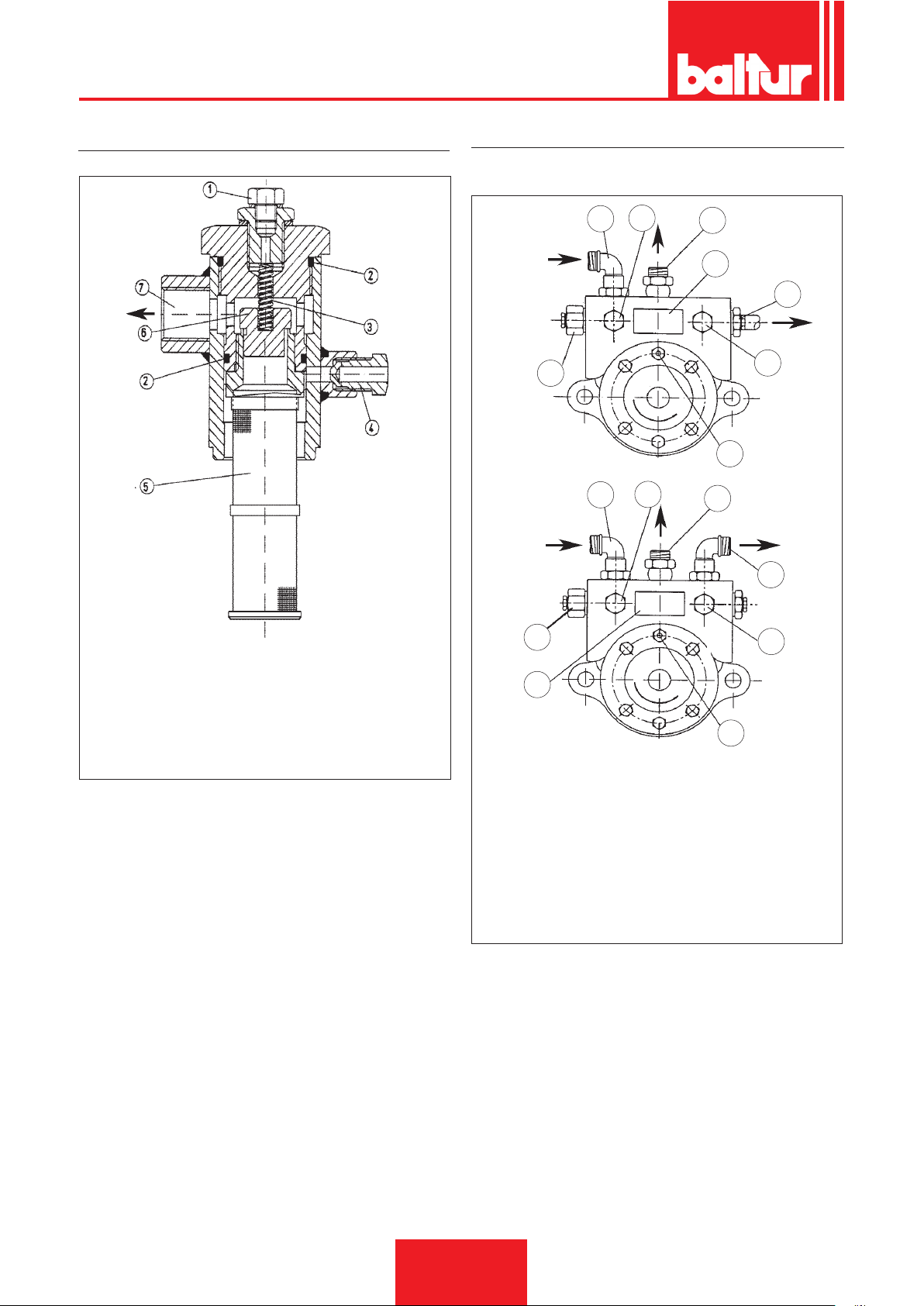
ENGLISH
TANK FILTER WITH GAS VALVE
BALTUR PUMP MOD. BT...
0002900570
8
2
1
3
4
0002900580
5
6
7
1
2
3
5
1) Pressure gauge connection Rp 1/2”
2) O-Ring
3) Valve closing spring (∆p 2÷3 bar)
4) Air vent cap
5) Mesh filter
6) Gas valve shutter
7) Fuel outlet to the spray nozzle unit
8
4
N° 0002932230
1 Intake
2 Vacuum gauge connection ¼”
3 Return
4 Pump data plate
5 Nozzle delivery
6 Pressure gauge connection ¼”
7 Heating element seat
8 Pump pressure regulation (20 -22 bar)
6
7
26 / 38
0006080547_201610
Page 69

NOZZLE FLOW RATE TABLE
ENGLISH
Nozzle
G.P.H. Nozzle output ow-rate G.P.H.
0.40 1.27 1.36 1.44 1.52 1.59 1.67 1.73 1.80 1.86 1.92 1.98 2.04 2.10 2.15 2.20 0.40
0.50 1.59 1.70 1.80 1.90 1.99 2.08 2.17 2.25 2.33 2.40 2.48 2.55 2.62 2.69 2.75 0.50
0.60 1.91 2.04 2.16 2.28 2.39 2.50 2.60 2.70 2.79 2.88 2.97 3.06 3.14 3.22 3.30 0.60
0.65 2.07 2.21 2.34 2.47 2.59 2.71 2.82 2.92 3.03 3.12 3.22 3.31 3.41 3.49 3.58 0.65
0.75 2.38 2.55 2.70 2.85 2.99 3.12 3.25 3.37 3.49 3.61 3.72 3.82 3.93 4.03 4.13 0.75
0.85 2.70 2.89 3.06 3.23 3.39 3.54 3.68 3.82 3.96 4.09 4.21 4.33 4.45 4.57 4.68 0.85
1.00 3.18 3.40 3.61 3.80 3.99 4.16 4.33 4.50 4.65 4.81 4.96 5.10 5.24 5.37 5.51 1.00
1.10 3.50 3.74 3.97 4.18 4.38 4.58 4.77 4.95 5.12 5.29 5.45 5.61 5.76 5.91 6.06 1.10
1.20 3.82 4.08 4.33 4.56 4.78 5.00 5.20 5.40 5.59 5.77 5.95 6.12 6.29 6.45 6.61 1.20
1.25 3.97 4.25 4.50 4.75 5.00 5.20 5.40 5.60 5.80 6.00 6.20 6.35 6.55 6.70 6.85 1.25
1.35 4.29 4.59 4.87 5.13 5.38 5.62 5.85 6.07 6.28 6.49 6.69 6.88 7.07 7.26 7.44 1.35
1.50 4.77 5.10 5.41 5.70 5.90 6.24 6.50 6.75 6.98 7.21 7.43 7.65 7.86 8.06 8.26 1.50
1.65 5.25 5.61 5.95 6.27 6.58 6.87 7.15 7.42 7.68 7.93 8.18 8.41 8.64 8.87 9.09 1.65
1.75 5.56 5.95 6.31 6.65 6.98 7.29 7.58 7.87 8.15 8.41 8.67 8.92 9.17 9.41 9.64 1.75
2.00 6.30 6.80 7.21 7.60 7.97 8.33 8.67 8.99 9.31 9.61 9.91 10.20 10.48 10.75 11.01 2.00
2.25 7.15 7.65 8.15 8.55 8.97 9.37 9.75 10.12 10.47 10.85 11.15 11.47 11.79 12.09 12.39 2.25
2.50 7.95 8.50 9.01 9.50 9.97 10.41 10.83 11.24 11.64 12.02 12.39 12.75 13.10 13.44 13.77 2.50
3.00 9.54 10.20 10.82 11.40 11.96 12.49 13.00 13.49 13.96 14.02 14.87 15.30 15.72 16.12 16.52 3.00
3.50 11.13 11.90 12.62 13.30 13.95 14.57 15.17 15.74 16.29 16.83 17.34 17.85 18.34 18.81 19.28 3.50
4.00 12.72 13.60 14.42 15.20 15.94 16.65 17.33 17.99 18.62 19.23 19.82 20.40 20.95 21.50 22.03 4.00
4.50 14.31 15.30 16.22 17.10 17.94 18.73 19.50 20.24 20.95 21.63 22.30 22.95 23.57 24.19 24.78 4.50
5.00 15.90 17.00 18.03 19.00 19.93 20.82 21.67 22.48 23.27 24.04 24.78 25.49 26.19 26.87 27.54 5.00
5.50 17.49 18.70 19.83 20.90
6.00 19.00 20.40 21.63 22.80 23.92 24.98 26.00 26.98 27.93 28.84 29.73 30.59 31.43 32.25 33.04 6.00
6.50 20.67 22.10 23.44 23.70 25.91 27.06 28.17 29.23 30.26 31.25 32.21 33.14 34.05 34.94 35.80 6.50
7.00 22.26 23.79 25.24 26.60 27.90 29.14 30.33 31.48 32.58 33.65 34.69 35.69 36.67 37.62 38.55 7.00
7.50 23.85 25.49 27.04 28.50 29.90 31.22 32.50 33.73 34.91 36.05 37.16 38.24 39.29 40.31 41.31 7.50
8.30 26.39 28.21 29.93 31.54 33.08 34.55 35.97 37.32 38.63 39.90 41.13 42.32 43.48 44.61 45.71 8.30
9.50 30.21 32.29 34.25 36.10 37.87 39.55 41.17 42.72 44.22 45.67 47.07 48.44 49.77 51.06 52.32 9.50
10.50 33.39 35.69 37.86 40.06 41.73 43.74 45.41 47.20 48.90 50.50 52.00 53.50 55.00 56.40 57.80 10.50
12.00 38.20 40.80 43.30 45.60 47.80 50.00 52.00 54.00 55.90 57.70 59.50 61.20 62.90 64.50 66.10 12.00
13.80 43.90 46.90 49.80 52.40 55.00 57.50 59.80 62.10 64.20 66.30 68.40 70.40 72.30 74.30 76.00 13.80
15.30 48.60 52.00 55.20 58.10 61.00 63.70 66.30 68.80 71.10 73.60 75.80 78.00 80.20 82.20 84.30 15.30
17.50 55.60 59.50 63.10 66.50 69.80 72.90 75.80 78.70 81.50 84.10 86.70 89.20 91.70 94.10 96.40 17.50
19.50 62.00 66.30 70.30 74.10 77.70 81.20 84.50 87.70 90.80 93.70 96.60 99.40 102.20 104.80 107.40 19.50
21.50 68.40 73.10 77.50 81.70 85.70 89.50 93.20 96.70 100.10 103.40 106.50 109.60 112.60 115.60 118.40 21.50
24.00 76.30 81.60 86.50 91.20 95.70 99.90 104.00 107.90 111.70 115.40 118.90 122.40 125.70 129.00 132.20 24.00
28.00 89.00 95.20 101.00 106.40 111.60 116.60 121.30 125.90 130.30 134.60 138.70 142.80 146.70 150.50 154.20 28.00
30.00 95.40 102.00 108.20 114.00 119.60 124.90 130.00 134.90 139.60 144.20 148.70 153.00 157.20 161.20 165.20 30.00
7 8 9 10 11 12 13 14 15 16 17 18 19 20 21
21.92 22.90 23.83 24.73 25.60 26.44 27.25 28.04 28.81 29.56 30.29 5.50
Pump pressure
Nozzle
1 mbar = 10 mmC.A. 100 Pa
1 kW = 860 kcal
Diesel density ......................................................... = 0.820 / 0.830 NHV = 10150
Special fuel density ................................................. = 0.900 NHV = 9920
Domestic fuel density (3.5°E) ................................ = 0.940 NHV = 9700
Heavy fuel density (7.9°E) ..................................... = 0.970 / 0.980 NHV = 9650
NHV = net heating value
27 / 38
0006080547_201610
Page 70
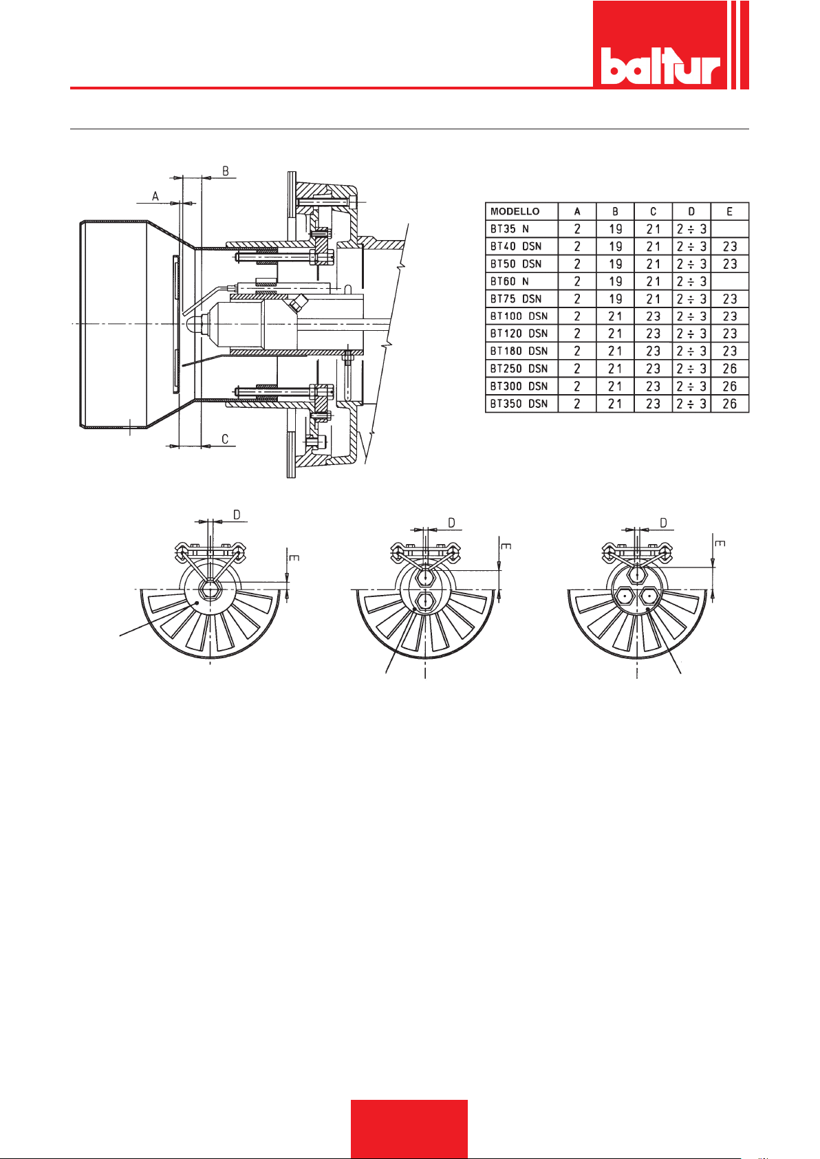
ENGLISH
SCHEMA INDICATIVO DISPOSIZIONE UGELLO - ELETTRODI - DISCO FIAMMA
N° 0002932311
Gruppo a 1 Ugello
1 nozzle atomizing group
Gruppo a 2 Ugelli
2 nozzles atomizing group
Gruppo a 3 Ugelli
3 nozzles atomizing group
28 / 38
0006080547_201610
Page 71
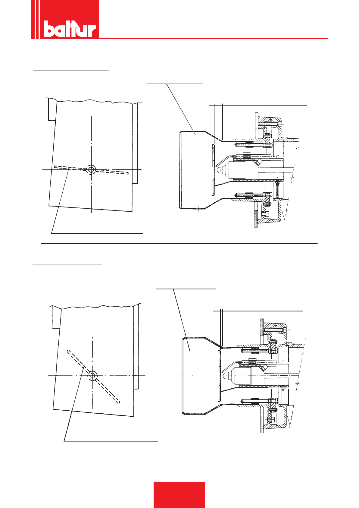
SCHEMA DI PRINCIPIO REGOLAZIONE ARIA
INCORRECT REGULATION
ENGLISH
Combustion head
Air ow large opening
Combustion air inlet with very locked shutter
CORRECT REGULATION
Combustion head
Air ow quite locked.
Attention: Avoid complete locking
Ingresso aria di combustione con serranda sensibilmente aperta
29 / 38
0006080547_201610
Page 72
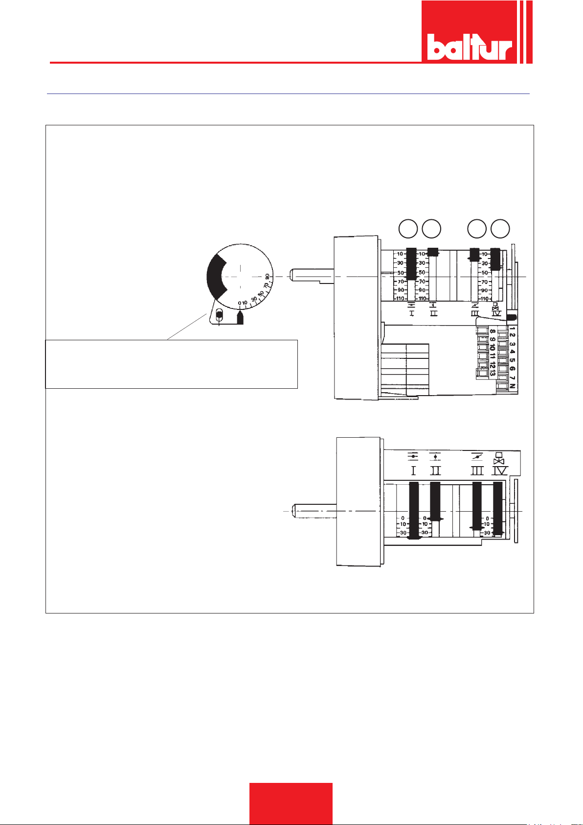
ENGLISH
SQN 30.111 A3500
PREVENTILATION WITH AIR OPEN (2nd FLAME POSITION) AIR CLOSED WITH BURNER IN STOP POSITION
1 - 2nd Flame valve connection cam (must be adjusted in a position between the 1st ame and the 2nd ame cam)
2 - Air regulation cam 1° ame
3 - Close air shutter cam with burner in stop position
nd
4 - Air regulation cam 2
ame
Motor-cam shaft coupling cutting out pin.
The switching-off of the motor and shaft connection can be
obtained by pushing.
In order to modify the cams regulation it's necessary to
intervene on the relative red rings. Pushing by sufcient
strength,in the sens one desires, each red ring can
turn in respect to the reffering scale. The pointer of the
red ring indicates on the respective reffering scale the
rotation angle set for each cam.
34 1
2
8653-1
30 / 38
0006080547_201610
Page 73
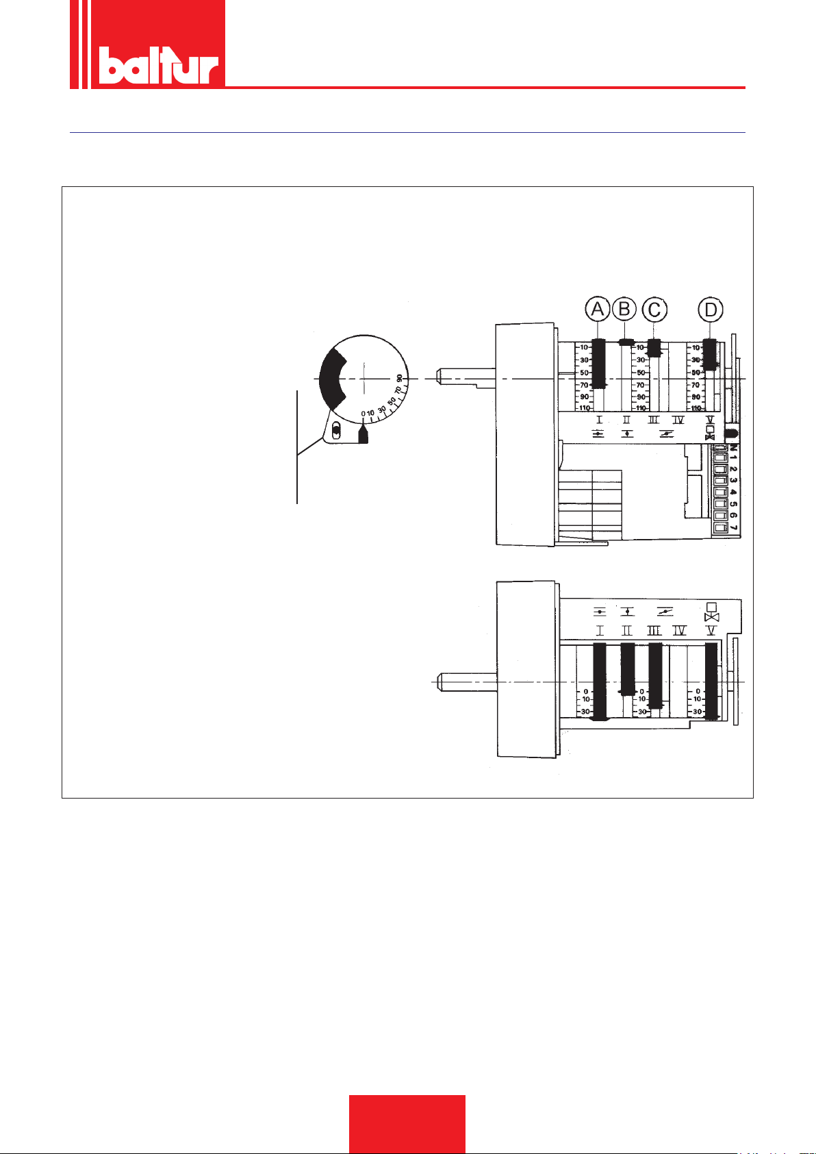
ENGLISH
SQN 30.121 A2700/3500
CLOSED AIR WITH STOPPED BURNER - PRE-VENTILATION WITH OPEN AIR (1st FLAME POSITION)
(WITH LOA... or OR 3B CONTROL BOX)
A - 2nd ame air regulation CAM
B - CAM: air gate shut when burner is not operating
C - 1st ame air regulation CAM
D - 2nd ame valve operation CAM
(must be set to intermediate position between 1st ame and 2nd ame cams)
- Motor - cam sheft coupling exclusion pin.
Push it to disconnect motor from cam
shaft.
8711-1
To change cam position, operate the rispective red rings.
By pushing hard enough in the desired direction, all the red
rings can rotate around the reference scale. The pointer of
the red ring indicates in 1st reference scale the rotation angle
set for each cam.
31 / 38
0006080547_201610
Page 74
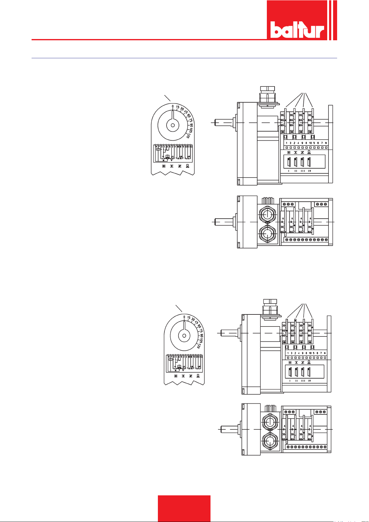
ENGLISH
“CONECTRON LKS 160”
AIR MOTOR REGULATION IN 1st FLAME
nd
I 2
FLAME AIR ADJUSTING CAM (60°)
st
II 1
FLAME AIR ADJUSTING CAM (20°)
III CAM NOT USED ( . . . °)
nd
IV 2
FLAME VALVE ACTUATING CAM (40°)
REFERENCE INDEX
ADJUSTABLE CAMS
0002934010
AIR MOTOR REGULATION IN 2
nd
FLAME AIR ADJUSTING CAM (60°)
I 2
II TOTAL AIR CLOSURE
(BURNER AT A STANDSTILL) (0°)
st
III 1
FLAME AIR ADJUSTING CAM (20°)
nd
IV 2
FLAME VALVE ACTUATING CAM (40°)
nd
FLAME
REFERENCE INDEX
ADJUSTABLE CAMS
0002934000
32 / 38
0006080547_201610
Page 75
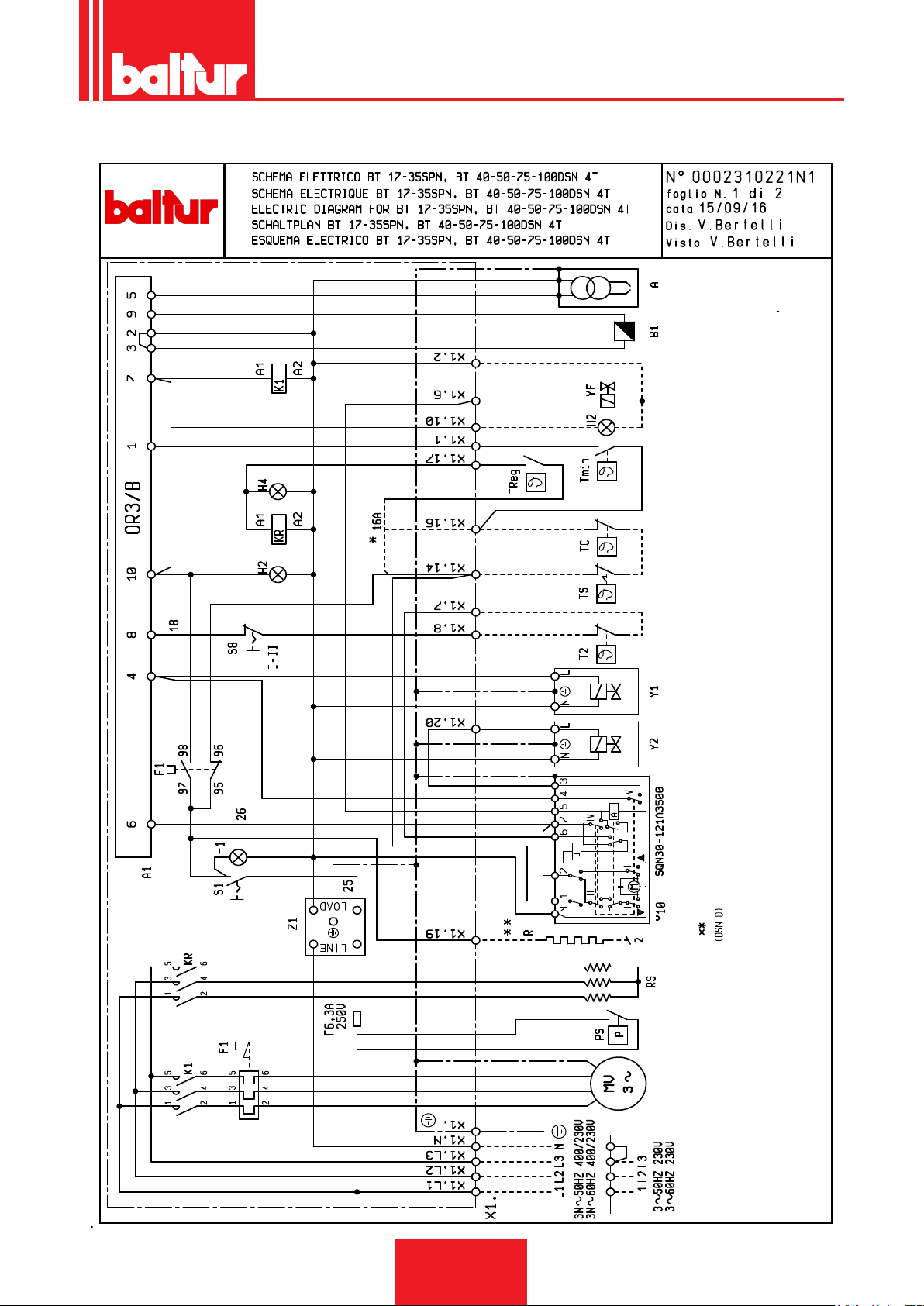
WIRING DIAGRAM
ENGLISH
"TC" MOVE WIRE 16A FROM TERMINAL 16 TO 14
* FOR HEATING ELEMENT CONTROL INDEPENDENT FROM
33 / 38
0006080547_201610
Page 76
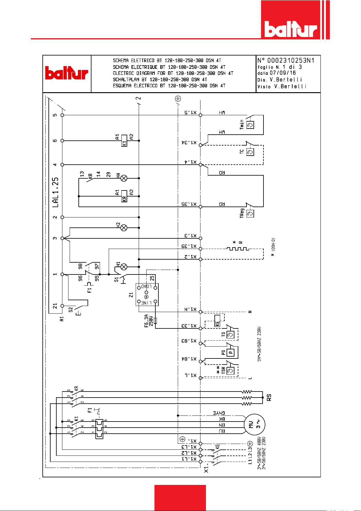
ENGLISH
34 / 38
0006080547_201610
** ONLY FOR BT 180 - 250 - 300
Page 77
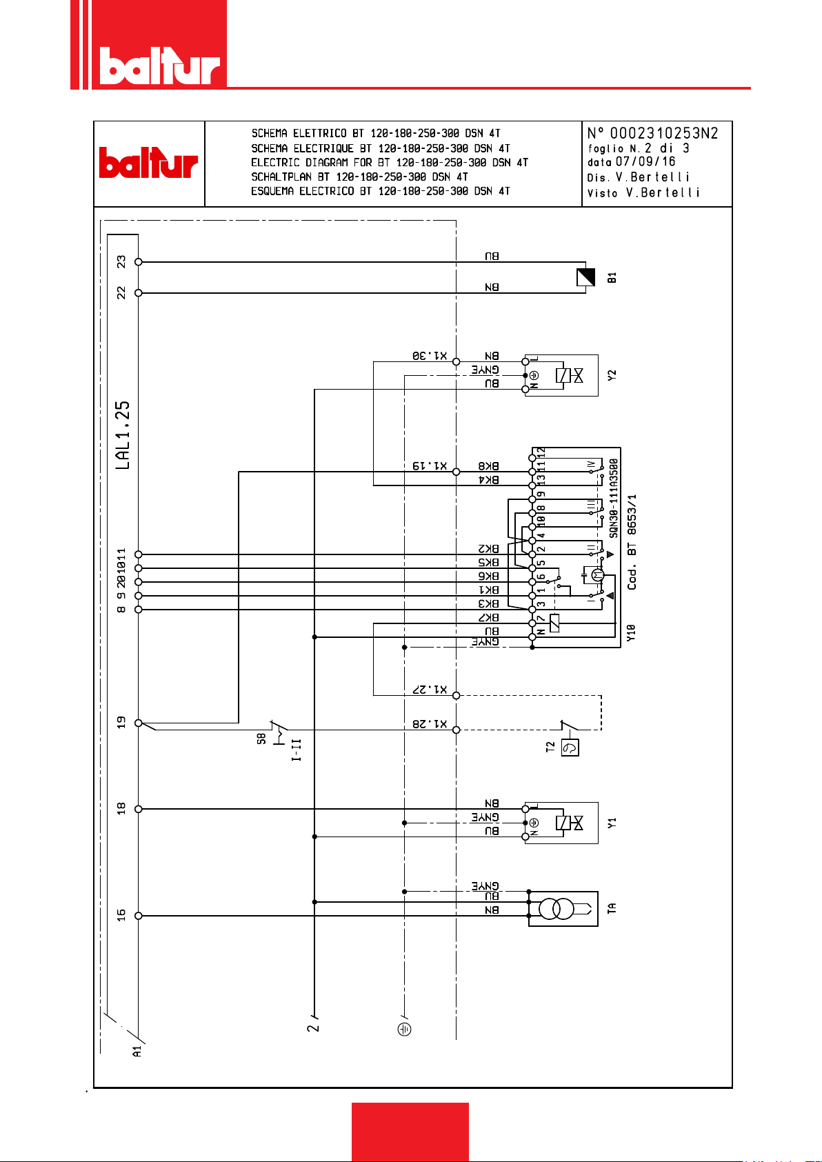
ENGLISH
35 / 38
0006080547_201610
Page 78
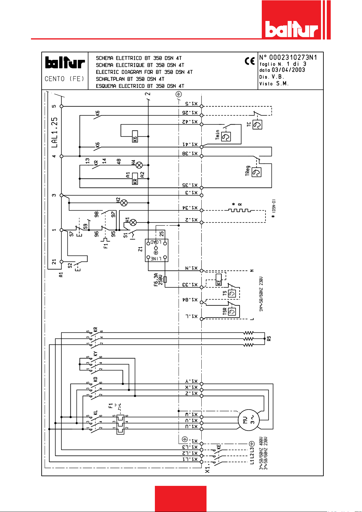
ENGLISH
36 / 38
0006080547_201610
Page 79
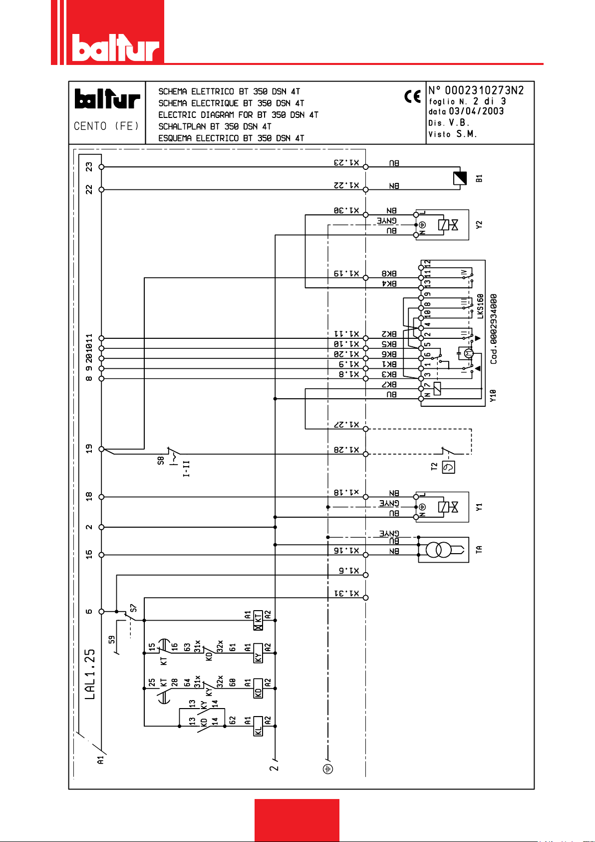
ENGLISH
37 / 38
0006080547_201610
Page 80

ENGLISH
ABBREVIATION EN
A1 EQUIPMENT
B1 - FR PHOTORESISTOR
F1 THERMAL CUTOUT
F2 PUMP THERMAL CUTOUT
HO EXTERNAL LOCK LIGHT/ AUXILIARY HEATING ELEMENT OPERATION
LAMP
H1 OPERATION WARNING LIGHT
H2 LOCK WARNING LIGHT
H4 HEATING ELEMENT LIGHT
K1 MOTOR RELAY
K2 PUMP MOTOR CONTACTOR
K6 AUXILIARY RELAY FOR HEATING ELEMENTS
KD TRIANGLE CONTACTOR
KE EXTERNAL CONTACTOR
KL LINE CONTACTOR
KR HEATING ELEMENT CONTACTOR
KT TIMER
KY STAR CONTACTOR
MP PUMP MOTOR
MV FAN MOTOR
PA AIR PRESSURE SWITCH
PS SAFETY PRESSURE SWITCH
RP.RF.RG PUMP, FILTER, UNIT HEATING ELEMENTS
RS - R HEATING ELEMENTS
S1 START/STOP SWITCH
S2 RELEASE BUTTON
S7 BUTTON "TANK FILLING"
S8 1st/- 2nd STAGE SWITCH
T2 2nd STAGE THERMOSTAT
TA IGNITION TRANSFORMER
TC BOILER THERMOSTAT
Tmin MINIMUM THERMOSTAT
Treg
HEATING ELEMENT REGULATION THERMOSTAT
TS SAFETY THERMOSTAT
TSR HEATING ELEMENT SAFETY THERMOSTAT
X1 BURNER TERMINAL BOARD
YE - VE EXTERNAL SOLENOID VALVE
Y1/Y2 - V1/V2 1ST / 2ND STAGE SOLENOID VALVES
Y10 AIR SERVOMOTOR
YS - VS SAFETY SOLENOID VALVE
Z1 - Z FILTER
38 / 38
0006080547_201610
Page 81

ESPAÑOL
DECLARACIÓN DE CONFORMIDAD
CE0085:
DVGW CERT GmbH, Josef-Wirmer Strasse 1-3-53123 Bonn (D)
Declaramos que nuestros quemadores de aire impulsado de combustibles líquidos, gaseosos y mixtos, domésticos e industriales, serie:
BPM...; BGN…; BT…; BTG…; BTL…; TBML...; Comist…; GI…; GI…Mist; Minicomist…; PYR…; RiNOx…; Spark...; Sparkgas...;
TBG...;TBL...; TS…; IBR...; IB...
(Variante: … LX, para bajas emisiones NOx)
cumplen los requisitos mínimos impuestos por las Directivas Europeas:
• 2009/142/CE (D.A.G.)
• 2004/108/CE (C.E.M.)
• 2006/95/CE (D.B.T.)
• 2006/42/CE (D.M.)
y han sido diseñados y ensayados según las Normas europeas:
• prEN 676:2012 (gas y mixtos, lado gas)
• prEN 267:2012 (gasóleo y mixtos, lado gasóleo)
• EN 60335-1 (2012-01) + EC (2014-01) (todos los quemadores)
Cento, 23 de enero de 2013
Director I&D
Paolo Bolognin
Administrador Delegado y Director General
Riccardo Fava
1 / 40
0006080537_201610
Page 82

ESPAÑOL
ADVERTENCIAS PARA EL USO EN CONDICIONES DE SEGURIDAD
OBJETO DEL MANUAL
El manual ayuda a utilizar el producto de manera segura proporcionando información sobre los comportamientos necesarios para
evitar alteraciones de las características de seguridad debido a
instalaciones incorrectas, usos inadecuados, impropios o no razonables.
Queda excluida toda responsabilidad contractual y extracontractual del fabricante por daños debidos a errores en la instalación,
en el uso y por no haber respetado las instrucciones dadas por el
fabricante en cuestión.
• La vida de las máquina es de al menos 10 años si se respetan
las condiciones normales de trabajo y se efectúa el mantenimiento periódico indicado por el fabricante.
• El libro de instrucciones constituye una parte integrante y esen-
cial del producto y tiene que entregarse al usuario.
• El usuario debe conservar con cuidado el libro para poder consultarlo en cualquier momento.
• Antes de empezar a utilizar el aparato, leer atentamente las
"Instrucciones de uso" contenidas en este manual y las
que se aplican directamente sobre el producto para reducir
al mínimo los riesgos y evitar accidentes.
• Respetar las ADVERTENCIAS DE SEGURIDAD, se prohíbe
todo tipo de USO IMPROPIO.
• El instalador debe analizar los posibles RIESGOS RESIDUALES.
• Para resaltar ciertas partes de texto o para indicar algunas ca-
racterísticas de importancia fundamental, se han utilizado los
símbolos descritos a continuación.
PELIGRO/ATENCIÓN
Indica una situación de grave peligro para la salud y la seguridad de las personas.
PRECAUCIÓN / ADVERTENCIAS
Indica que es necesario adoptar comportamientos adecuados para no poner en peligro la salud y la seguridad de las
personas ni provocar daños económicos.
IMPORTANTE
Muestra información técnica y operativa de importancia
fundamental que se debe respetar.
posean la experiencia y los conocimientos adecuados.
• el aparato sólo puede ser utilizado por dichas persona si han
recibido la información relativa a su seguridad y al uso del aparato y bajo la supervisión de una persona responsable.
• Vigilar en todo momento a los niños para evitar que jueguen
con el aparato.
• Este aparato está destinado sólo para el uso expresamente
previsto. Cualquier otro uso se considera impropio y por lo
tanto peligroso.
• La instalación del aparato debe realizarse respetando las nor-
mas vigentes, según las instrucciones del fabricante, y tiene
que realizarla el personal cualicado profesionalmente.
• El personal cualicado profesionalmente son los operadores
que poseen la competencia técnica especíca y certicada en
el sector, de acuerdo con as normas locales vigentes.
• Una instalación errónea pueda causar daños a personas, ani-
males y cosas, de los que el fabricante no se hace responsable.
• Después de haber quitado todo el embalaje hay que asegurarse de que el contenido esté íntegro. En caso de dudas no
utilice el aparato y diríjase al proveedor. No dejar los elementos
del embalaje al alcance de los niños ya que son fuentes potenciales de peligro.
• La mayoría de los componentes del aparato se compone de
materiales que pueden ser reutilizados. El embalaje y el apa-
rato no pueden ser eliminados con los normales desechos
domésticos, ya que son susceptibles de ser eliminados en
cumplimiento de las normativas vigentes.
• Antes de realizar cualquier operación de limpieza o de mantenimiento hay que desconectar el aparato de la red de alimentación eléctrica mediante el interruptor de la instalación con los
órganos de corte a tal efecto.
• Si el aparato se vende o pasa a otro propietario, o si usted se
muda de casa y deja el aparato, hay que asegurarse siempre
de que el libro de instrucciones esté siempre con el aparato
para que pueda ser consultado por el nuevo propietario y/o in-
stalador.
• No tocar los componentes calientes próximos a la llama y al sistema de precalentamiento del combustible cuando el aparato
está funcionando. Su temperatura puede ser elevada incluso
durante largo tiempo incluso después de haber apagado el
aparato.
• Para todos los aparatos con elementos opcionales o kits ( inclu-
idos los eléctricos) hay que utilizar solo accesorios originales.
CONDICIONES Y DURACIÓN DEL ALMACENAMIENTO
Los aparatos se envían con el embalaje del fabricante y se transportan por carretera, por mar y por ferrocarril de conformidad
con las normas para el transporte de mercancías en vigor para el
medios real de transporte utilizado.
Es necesario almacenar los equipos no utilizados en locales cerrados con una adecuada circulación de aire en condiciones están-
dar (temperatura entre -10° C y + 40° C).
El periodo de almacenamiento es de 3 años.
ADVERTENCIAS GENERALES
• La fecha de producción del aparato (mes, año) se indica en la
placa de identicación del quemador presente en el aparato.El
aparato no debe ser utilizado por personas (niños incluidos)
con discapacidades físicas, sensoriales o mentales o que no
0006080537_201610
2 / 40
Page 83

ESPAÑOL
• En caso de avería y/o mal funcionamiento del aparato hay que
desactivarlo, absteniéndose de realizar cualquier intento de
reparación o intervención directa. Diríjase exclusivamente al
personal cualicado profesionalmente.
• La eventual reparación de los aparatos tiene que hacerla solamente un centro de asistencia autorizado por BALTUR o por
su distribuidor local utilizando exclusivamente repuestos originales.
• El fabricante y su distribuidor local se eximen de toda responsabilidad en caso de accidente o daño causado por modicaciones no autorizadas del producto o por el incumplimiento de las
instrucciones contenidas en este manual.
ADVERTENCIAS DE SEGURIDAD PARA LA INSTALACIÓN
• El local de instalación del aparato debe disponer de ventilación
adecuada conforme con las normas y leyes vigentes.
• La sección de las rejillas de aspiración del aire y las aberturas
de ventilación del local de instalación no deben estar obstruidas
de manera parcial ni total.
• El local de instalación NO debe presentar riesgo de explosión
ni de incendio.
• Antes de efectuar la instalación, se recomienda limpiar a fondo
el interior de todos los tubos del circuito de alimentación del
combustible.
• Antes de conectar el aparato hay que asegurarse de que los
datos de las placa correspondan con los de la red de alimenta-
ción (eléctrica, gas, gasóleo u otro combustible).
• Comprobar que el quemador esté jado al generador de calor
tal y como previsto por el fabricante.
• Efectuar las conexiones a las fuentes de energía de manera
correcta respetando los esquemas de referencia y las normas
en vigor en el momento de instalación.
• Comprobar que el sistema de extracción del humo NO esté
obstruido.
• Cuando se decida no utilizar denitivamente el quemador, hay
que encargar al personal cualicado profesionalmente que realice las operaciones siguientes:
- Desconectar la alimentación eléctrica quitando el cable de
alimentación del interruptor general.
- Cerrar la alimentación del combustible por medio de la
válvula de corte y quitar los volantes de mando de su
alojamiento.
- Hacer que sean inocuas las partes que podrían ser poten-
ciales fuentes de peligro.
prendida entre los valores indicados en la placa del quemador
y/o del manual.
• Que la instalación de alimentación del combustible esté dimen-
sionada para el caudal necesario del quemador y que tenga
todos los dispositivos de seguridad y control prescritos por las
normas vigentes.
• Antes de poner en marcha el quemador y por lo menos una
vez al año, el personal cualicado profesionalmente tiene que
realizar las siguientes operaciones:
- Regular el caudal del combustible del quemador según la
potencia que requiere el generador de calor.
- Controlar la combustión y regular el caudal de aire comburente y/o de combustible para optimizar el rendimiento
de combustión y las emisiones de acuerdo con las normas
vigentes.
- Comprobar que funcionen bien los dispositivos de regulación y seguridad.
- Comprobar que funcione correctamente el conducto de
expulsión de los productos de la combustión.
- Controlar la estanqueidad en el tramo interior y exterior de
los tubos de alimentación del combustible.
- Al nal de todas las regulaciones controlar que todos los
sistemas de bloqueo mecánico de los dispositivos de regulación estén bien apretados.
- Asegurarse de que las instrucciones de uso y mantenimiento del quemador puedan ser consultadas.
• Si el quemador se para bloqueándose varias veces no hay que
insistir rearmándolo manualmente; diríjase al personal cuali-
cado profesionalmente.
• Si se decide no utilizar el quemador durante un cierto periodo
hay que cerrar la llave o llaves de alimentación del combustible.
ADVERTENCIAS PARA LA PUESTA EN FUNCIONAMIENTO,
LA PRUEBA DE ENSAYO, EL USO Y EL MANTENIMIENTO
• La puesta en funcionamiento, la prueba de ensayo y el man-
tenimiento deben ser efectuados exclusivamente por personal
cualicado profesionalmente, de acuerdo con cuanto previsto
por las normas vigentes.
• Una vez jado el quemador al generador de calor, comprobar
durante la prueba de ensayo que no existan pérdidas de llama
por eventuales suras.
• Controlar la estanqueidad de los tubos de alimentación del
combustible del aparato.Comprobar que el caudal de combustible coincida con la potencia requerida al quemador.
• Regular el caudal del combustible del quemador según la potencia que requiere el generador de calor.
• La presión de alimentación del combustible debe estar com-
0006080537_201610
3 / 40
Page 84

ESPAÑOL
Advertencias particulares para el uso del gas.
• Comprobar que la línea de abastecimiento de combustible y la
rampa se ajusten a las normativas vigentes.
• Que todas las conexiones del gas sean estancas.
• No dejar el aparato inútilmente conectado cuando no se utilice
y cerrar siempre la llave del gas.
• En caso de ausencia prolongada del usuario del aparato hay
que cerrar la llave principal que abastece gas al quemador.
• Si se advierte olor de gas:
- no accionar los interruptores eléctricos, el teléfono ni cual-
quier otro objeto que pueda provocar chispas;
- abrir inmediatamente puertas y ventanas para crear una
corriente de aire que purique el local;
- cerrar la llave del gas;
- pedir que intervenga el personal cualicado profesionalmente.
• No obstruir las aberturas de ventilación del local donde está
instalado un aparato de gas para evitar situaciones peligrosas
como la formación de mezclas tóxicas y explosivas.
RIESGOS RESIDUALES
• A pesar del minucioso diseño del producto respetando las nor-
mas obligatorias y de las buenas reglas en el uso correcto pueden permanecer riesgos residuales. Estos son señalados en el
quemador con los pictogramas correspondientes.
metálicas.
• La alimentación eléctrica del quemador tiene que tener el neu-
tro a tierra. En caso de supervisión de la corriente de ionización
con el neutro no conectado a tierra es indispensable conectar
entre el borne 2 (neutro) y la tierra el circuito RC.
• En caso de ausencia prolongada del usuario del aparato hay
que cerrar la llave principal que abastece gas al quemador.
• El uso de cualquier componente que utilice energía eléctrica
comporta el respeto de algunas reglas fundamentales como:
- no tocar el aparato con partes del cuerpo mojadas o húmedas y/o con los pies descalzos;
- no tirar de los cables eléctricos;
- no dejar el aparato expuesto a agentes atmosféricos (lluvia,
sol, etc.) de no ser que no esté expresamente previsto;
- no permitir que el aparato lo usen niños o personas inexpertas;
- El cable de alimentación del aparato no tiene que cambiarlo
el usuario. Si el cable está dañado, apagar el aparato. Para
sustituirlo, contactar con personal profesional cualicado;
- Si decide no utilizar el aparato durante un cierto periodo es
oportuno apagar el interruptor eléctrico de alimentación de
todos los componentes de la instalación que utilizan energía
eléctrica (bombas, quemador, etc.).
ATENCIÓN
Órganos mecánicos en movimiento.
ATENCIÓN
Materiales a temperaturas elevadas.
ATENCIÓN
Cuadro eléctrico bajo tensión.
ADVERTENCIAS DE SEGURIDAD ELÉCTRICA
• Comprobar que el aparato posea un sistema de toma de tierra
adecuado, que cumpla las normas de seguridad vigentes.
• No utilizar los tubos del gas como puesta a tierra de aparatos
eléctricos.
• En caso de dudas, pida al personal cualicado que haga un
control detenido de la instalación eléctrica pues el fabricante
no se hace responsable de los posibles daños causados por la
falta de puesta a tierra de la instalación.El personal profesional
cualicado debe comprobar que la instalación eléctrica es adecuada para la potencia máxima absorbida indicada en la placa.
• Comprobar que la sección de los cables de la instalación sea
adecuada para el consumo de corriente del aparato.
• No se permite utilizar adaptadores, tomas múltiples ni alarga-
dores para conectar la alimentación general del aparato a la
red eléctrica.
• Prevea un interruptor omnipolar con distancia de apertura de
los contactos igual o superior a 3 mm para la conexión a la red
eléctrica, como está previsto por las normativas de seguridad
vigentes (condición de la categoría de sobretensión III).
• Para la alimentación eléctrica del quemador utilice exclusivamente cables de doble aislamiento, con aislamiento externo de
al menos 1 mm de espesor.
• Elimine el aislante exterior del cable de alimentación en la
medida que se considere necesaria para realizar la conexión,
evitando así que el hilo pueda entrar en contacto con partes
4 / 40
0006080537_201610
Page 85

CARACTERÍSTICAS TÉCNICAS
ESPAÑOL
CAUDAL MÍN Kg/h
MÁX Kg/h
POTENCIA TÉRMICA MÍN kW
MÁX. kW
vers. normal
VISCOSIDAD COMBUSTIBLE
MOTOR DEL VENTILADOR kW
versión Denso
r.p.m. 2800 2800 2800 2810 2825
TRANSFORMADOR VOLT/VOLTIOS
TENSIÓN TRIFÁSICO
RESISTENCIA PRECALENTADOR
MATERIAL DE EQUIPO
BT 40
DSN-4T
BT 50
DSN-4T
BT 75
DSN-4T
BT 100
DSN-4T
20 28 40 50 60
40 50 75 100 130
223 312 446 558 669
446 558 837 1116 1451
7°E - 50°C 7°E - 50°C 7°E - 50°C 7°E - 50°C 7°E - 50°C
20°E - 50°C 20°E - 50°C 20°E - 50°C 20°E - 50°C 20°E - 50°C
0,55 1,1 1,1 1,5 2,2
10kV -
30mA
10kV -
30mA
10kV -
30mA
12kV -
30mA
3 N ~ 400V ± 10% 50 Hz
kW
3,2 6 6 7,5 10,5
BT 120
DSN-4T
12kV -
30mA
JUNTA AISLANTE
PRISIONEROS
TUERCAS HEXAGONALES
ARANDELAS PLANAS
TUBOS FLEXIBLES
NIPLES
FILTRO
N.° 1 N.° 1 N.° 1 N.° 1 N.° 1
N.° 4 - M12 N.° 4 - M12 N.° 4 - M12 N.° 4 - M12 N.° 4 - M12
N.° 4 - M12 N.° 4 - M12 N.° 4 - M12 N.° 4 - M12 N.° 4 - M12
N° 4 - Ø12 N° 4 - Ø12 N° 4 - Ø12 N° 4 - Ø16 N° 4 - Ø16
N.°1 - 3/4”
N°1 - 1”
N°1 - 3/4”x1” N°1 - 3/4”x1” N°1 - 3/4”x1” N°1 - 3/4”x1” N°1 - 3/4”x1”
N°1 - 1”x1” N°1 - 1”x1” N°1 - 1”x1” N°1 - 1”x1” N°1 - 1”x1”
1” 1” 1” 1” 1”
N.°1 - 3/4”
N°1 - 1”
N.°1 - 3/4”
N°1 - 1”
N.°1 - 3/4”
N°1 - 1”
N.°1 - 3/4”
N°1 - 1”
5 / 40
0006080537_201610
Page 86
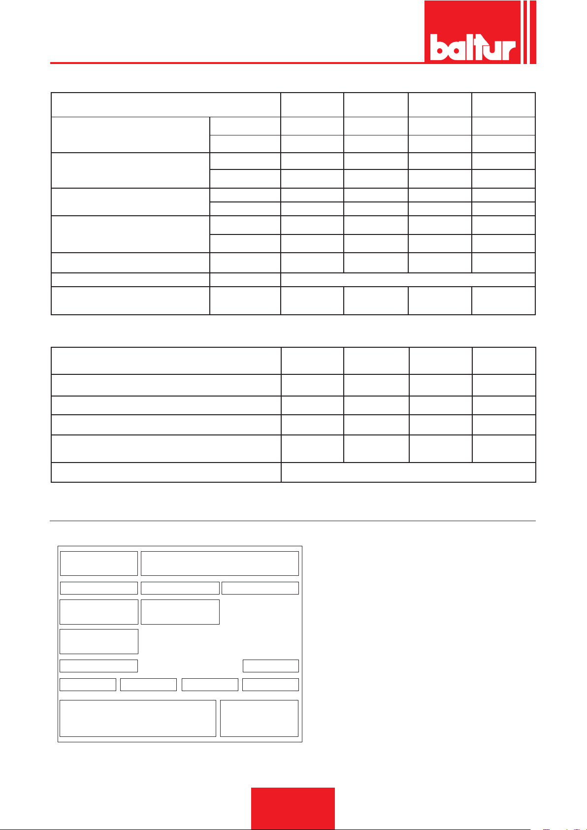
Targa_descr_bru
ESPAÑOL
MÍN Kg/h
CAUDAL
POTENCIA TÉRMICA
VISCOSIDAD COMBUSTIBLE
MOTOR VENTILADOR
TRANSFORMADOR VOLT/VOLTIOS
TENSIÓN TRIFÁSICA
RESISTENCIA PRECALENTADOR kW
MÁX Kg/h
MÍN kW
MÁX. kW
vers. normal
versión Denso
kW
r.p.m. 2870 2870 2870 2900
BT 180
DSN-4T
65 90 110 115
180 280 325 350
725 937 1220 1284
2009 3170 3460 3907
7° E - 50° C 7° E - 50° C 7° E - 50° C 7° E - 50° C
20° E - 50° C 20° E - 50° C 20° E - 50° C 20° E - 50° C
3 7,5 7,5 9
14kV - 30mA 14kV - 30mA 14kV - 30mA 14kV - 30mA
15 18 25,5 28,5
BT 250
DSN-4T
3 N ~ 400V ± 10% 50 Hz
BT 300
DSN-4T
BT 350
DSN-4T
MATERIAL DE EQUIPO
JUNTA AISLANTE N.° 1 N.° 1 N.° 1 N.° 1
PRISIONEROS N.° 4 - M12 N.° 4 - M12 N.° 4 - M18 N.° 4 - M18
TUERCAS HEXAGONALES N.° 4 - M12 N.° 4 - M12 N.° 4 - M18 N.° 4 - M18
ARANDELAS PLANAS N.° 4 - Ø16 N.° 4 - Ø16 N.° 4 - Ø18 N.° 4 - Ø18
TUBOS FLEXIBLES
N.°1 - 3/4"
N.°1 - 1"1/4
N.°1 - 3/4"
N.°1 - 1"1/4
N.°2 - 1" 1/4 N.°2 - 1" 1/4
FILTRO 1”1/4
PLACA DE IDENTIFICACIÓN DEL QUEMADOR
1 Logo de le empresa
2 Razón social de la empresa
1 2
3 4 5
6 7
8
9
10 13
11
12
14
1615
3 Código del producto
4 Modelo del quemador
5 Matrícula
6 Potencia de los combustibles líquidos
7 Potencia de los combustibles gaseosos
8 Presión de los combustibles gaseosos
9 Viscosidad de los combustibles líquidos
10 Potencia del motor del ventilador
11 Tensión de alimentación
12 Grado de protección
13 País de construcción y números de certicado de homologa-
ción
14 Año de fabricación
15 -
16 Código de barras de la matrícula del quemador
6 / 40
0006080537_201610
Page 87
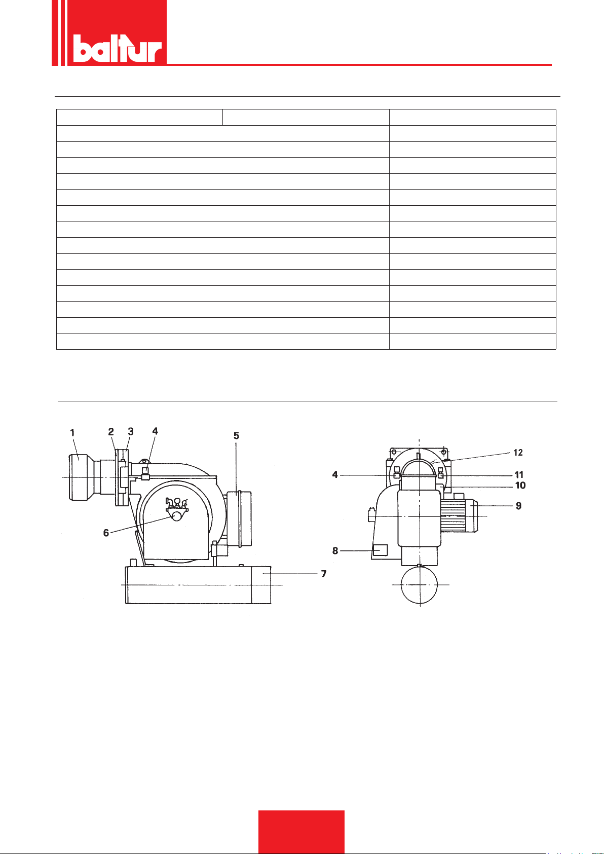
DATOS DE REGISTRO DEL PRIMER ENCENDIDO
Modelo: Fecha: ahora:
Tipo de gas
Índice de Wobbe inferior
Potencia caloríca inferior
Caudal del gas
Caudal mín. del gas
Caudal mín del gas
Potencia mín. del gas
potencia máx. del gas
Presión del gas de red
Presión del gas tras el estabilizador
CO
CO2
temperatura de los humos
temperatura del aire
Stm3/h
Stm³/h
Stm³/h
kW
kW
mbar
mbar
ESPAÑOL
DESCRIPCIÓN DE LOS COMPONENTES
1) CABEZAL DE COMBUSTIÓN
2) JUNTA AISLANTE
3) BISAGRA
a
4) ELECTROVÁLVULA 1
5) ARMARIO ELÉCTRICO
6) POMPA
7) PRECALENTADOR
8) SERVOMOTOR DE REGULACIÓN DEL AIRE
9) MOTOR VENTILADOR
10) TRANSFORMADOR DE ENCENDIDO
11) ELECTROVÁLVULA 2
12) FOTORRESISTENCIA
ETAPA (normalmente cerrada)
a
ETAPA (normalmente cerrada)
02370281A-tif
7 / 40
0006080537_201610
Page 88
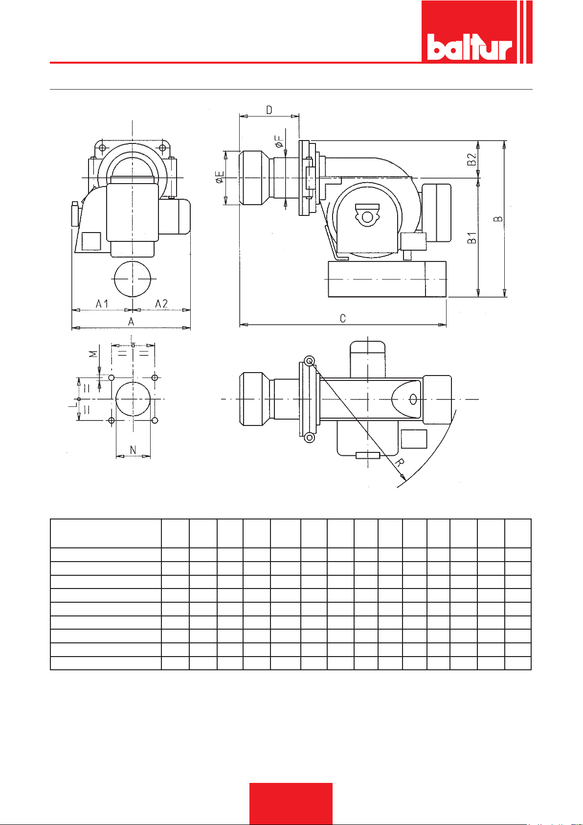
ESPAÑOL
DIMENSIONES TOTALES
02370281B-tif
MODELO A A1 A2 B B1 B2 C D E F L M N R
Ø Ø Ø
BT 40 DSN 4T/DSN 4T-D 560 300 260 615 465 150 735 145 155 135 230 M 12 170 595
BT 50 DSN 4T/DSN 4T-D 660 340 320 730 580 150 835 145 155 135 230 M 12 170 705
BT 75 DSN 4T/DSN 4T-D 660 340 320 740 580 150 910 220 205 170 230 M 12 220 705
BT 100 DSN 4T/DSN 4T-D 660 340 320 740 580 150 965 265 230 195 240 M 12 240 705
BT 120 DSN 4T/DSN 4T-D 690 320 370 825 665 160 1125 265 230 195 240 M 12 240 865
BT 180 DSN 4T/DSN 4T-D 755 385 370 900 720 180 1210 280 260 225 280 M 16 275 940
BT 250 DSN 4T/DSN 4T-D 945 465 480 1030 850 180 1235 295 260 225 280 M 16 275 940
BT 300 DSN 4T/DSN 4T-D 945 465 490 1170 945 225 1530 420 356 280 360 M 16 370 1135
BT 350 DSN 4T/DSN 4T-D 1085 525 560 1225 1000 225 1530 420 356 280 360 M 16 370 1135
8 / 40
0006080537_201610
Page 89
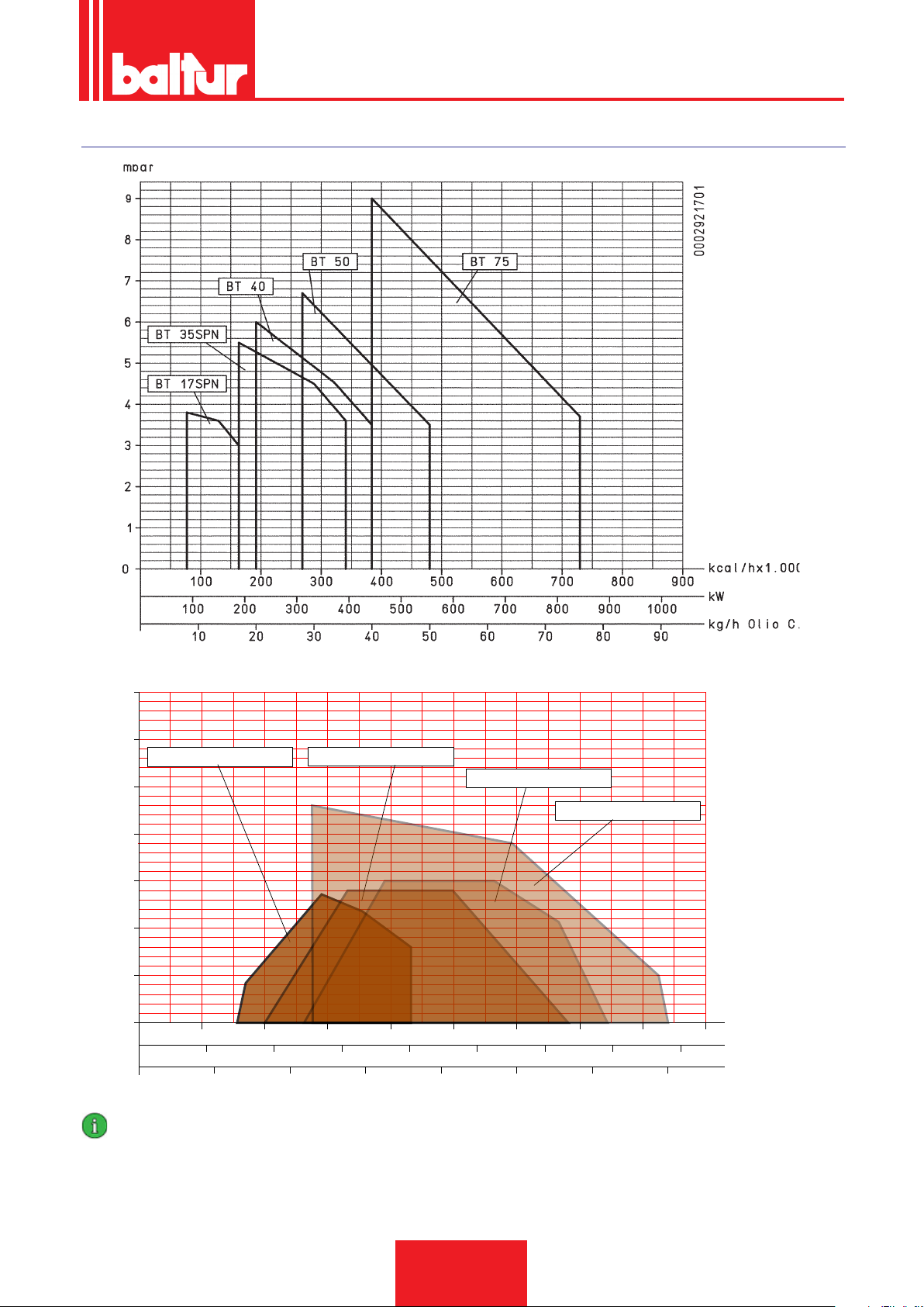
CAMPO DE TRABAJO
40 80
160
200
1000
240 280 320 360
kcal/hx10.000
2000 3000
4000
50
100 150
200 250 300 350
5
10
15
20
0
25
30
500
1500
2500 3500
35
120
0002921710
kW
kg/h
mbar
BT 180 DSPN / DSNM-D
BT 250 DSPN / DSNM-D
BT 300 DSPN / DSNM-D
BT 350 DSPN / DSNM-D
ESPAÑOL
IMPORTANTE
Los rangos de trabajo se obtienen en calderas de prueba conformes a la norma EN267 y son indicativos para los acoplamientos
quemador-caldera. Para el funcionamiento correcto del quemador las dimensiones de la cámara de combustión deben ser conformes con la normativa vigente; en caso contrario, es necesario consultar a los fabricantes.
El quemador no debe funcionar fuera del campo de trabajo dado.
0006080537_201610
9 / 40
Page 90
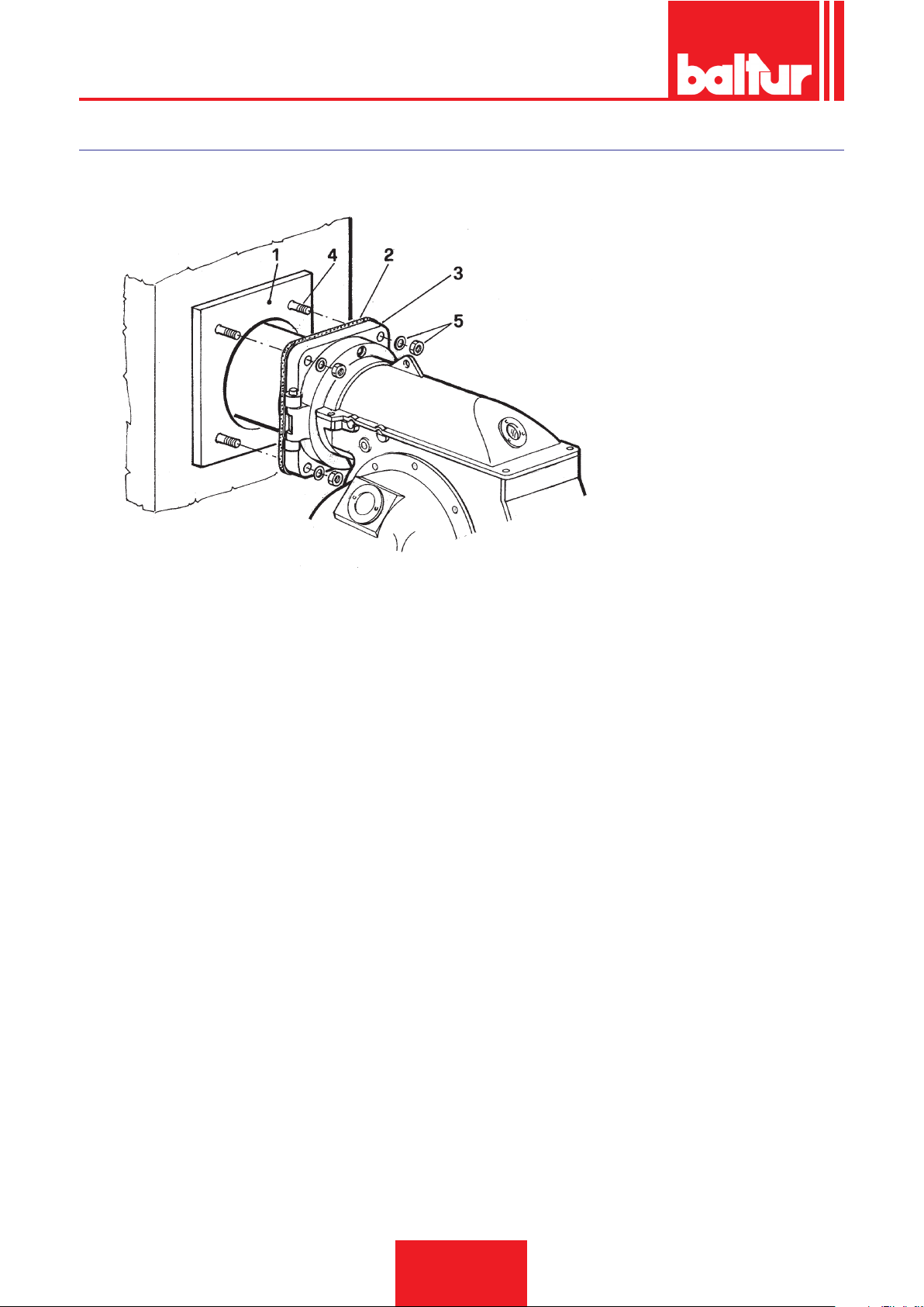
ESPAÑOL
APLICACIÓN DEL QUEMADOR A LA CALDERA
N° 0002933630
1 - Placa de la caldera
2 - Brida de material aislante
3 - Brida de jación del quemador
4 - Prisionero
5 - Tuerca y arandela de bloqueo
NOTA: La profundidad de penetración del cabezal debe ser indicada con precisión por el fabricante de la caldera.
El quemador está acoplado de forma correcta si el depósito precalentador está ligeramente inclinado (más alto en la parte de salida del
combustible hacia la boquilla) para evitar la posibilidad de que se acumule gas en el depósito. La presencia de gas en el precalentador
aumenta considerablemente el tiempo necesario para poner el combustible en presión y, por lo tanto, es probable que el quemador se
bloquee. Cuando se aplica a la caldera es preciso controlar que el quemador esté colocado en dicha posición inclinada o que, peor aún,
el precalentador no esté inclinado hacia la dirección contraria a aquella indicada.
10 / 40
0006080537_201610
Page 91

ESPAÑOL
INDICACIONES PARA REALIZAR UNA BUENA INSTALACIÓN
Antes de comenzar la instalación es preciso comprobar que:
1) La chimenea (sección y altura) sea conforme a las disposiciones de Ley.
2) Cuando se requiere la realización de un revestimiento refractario de la cámara de combustión (en función del tipo de
caldera) se deben seguir las instrucciones exactas del fabricante de la caldera.
3) La instalación eléctrica de alimentación del quemador debe hacerse según nuestro esquema y las conexiones eléctricas
en el quemador deben prepararse especialmente para la tensión de la línea de alimentación.
4) Los conductos del combustible se deben realizar según nuestros esquemas.
5) La boquilla o las boquillas instaladas en el quemador deben ser adecuadas para la potencia de la caldera y si fuera necesario se deben sustituir con otras. La cantidad de combustible suministrado no debe jamás superar la cantidad máxima
requerida por la caldera y admitida por el quemador. Es importante recordar que el cabezal de combustión ha sido diseñado para boquillas con ángulo de rociado de 45°. Sólo en casos extraordinarios se podrán usar boquillas con ángulo
de rociado diferente, pero en ese caso, hay que comprobar que dichas boquillas diferentes no causen inconvenientes
(desprendimiento de llama, ensuciamiento del disco o del cabezal de combustión, encendidos bruscos, etc...).
6) Al quitar el tapón de plástico del alojamiento de la boquilla se debe prestar atención porque si la supercie de estanqueidad
se daña (es suciente una leve hendidura) causa el goteo de combustible.
7) Comprobar que la boca del quemador penetre en la cámara de combustión según las indicaciones del fabricante de la
caldera.
CONEXIONES ELÉCTRICAS
Todas las conexiones deben llevarse a cabo con cable eléctrico exible.
Las líneas eléctricas se deben colocar oportunamente lejos de las piezas calientes. Es necesario asegurarse de que la línea
eléctrica a la cual se conecta el equipo reciba la tensión y la frecuencia adecuadas para el quemador. Comprobar que la línea
principal, el interruptor con fusibles (indispensable) y el limitador, en caso de que se utilice, sean adecuados para soportar la
corriente máxima absorbida por el quemador. Para más información, ver los esquemas eléctricos correspondientes a cada
quemador.
TUBERÍA DEL COMBUSTIBLE
A continuación se expone sólo lo que se considera necesario para asegurar un buen funcionamiento. El equipo dispone de
bomba autoaspirante capaz de aspirar directamente el aceite del tanque incluso para el primer llenado. Esto es verdad si
existen las condiciones necesarias (consultar la tabla relativa a las distancias y a los desniveles y el diagrama de viscosidadtemperatura). Para garantizar un buen funcionamiento es preferible que las tuberías de aspiración y de retorno se efectúen
con uniones soldadas, evitando las de rosca puesto que éstas a menudo permiten inltraciones de aire que comprometen el
funcionamiento correcto de la bomba y, por tanto, del quemador. Cuando es indispensable realizar una unión desmontable,
se debe usar el sistema de bridas soldadas con una junta interpuesta, resistente al combustible, para asegurar un sellado
perfecto. En las instalaciones donde se precisa utilizar una tubería con un diámetro relativamente pequeño, aconsejamos el
uso del tubo de cobre. Para las uniones inevitables, se recomienda el uso de racores de «bicono».
Las tablas a continuación ilustran los esquemas generales para los distintos tipos de instalaciones, en función de la posición
del tanque respecto al quemador. La tubería de aspiración se debe colocar hacia arriba en dirección del quemador para evitar
la posible acumulación de burbujas de gas. Si se instalan varios quemadores en el mismo cuarto de calderas, es indispensable
que cada quemador disponga de un tubo de aspiración propio. Sólo los tubos de retorno pueden conuir en un único tubo con
sección adecuada para llegar al tanque. Se debe evitar siempre la conexión directa del tubo de retorno al tubo de aspiración.
Se recomienda aislar correctamente las tuberías de aspiración y de retorno para evitar que las bajas temperaturas perjudiquen
su funcionamiento. Los diámetros de las tuberías (que se deben respetar estrictamente) se indican en las siguientes tablas.
La depresión máxima que la bomba puede soportar cuando funciona normalmente y silenciosamente es igual a 35 cm.Hg.;
si se supera este valor, no se garantiza un funcionamiento regular de la bomba.
Presión máxima en aspiración y retorno = 1 bar. Cuando se emplea un aceite combustible con una viscosidad superior al
límite de bombeo (ver diagrama) será necesario calentarlo a una temperatura que permita su ujo en las tuberías. El precalentamiento en el tanque se puede realizar con un serpentín de vapor, o bien con un serpentín de agua caliente. El serpentín
se debe instalar cerca del tubo de aspiración y en una posición que esté siempre sumergido, incluso cuando el depósito está
a nivel mínimo. La magnitud de dicho precalentamiento se determina consultando el diagrama de viscosidad - temperatura.
Se debe calentar el aceite hasta que su viscosidad alcance un valor debajo de la línea mínima de bombeo. Un ligero precalentamiento en el tanque es siempre ventajoso también si se usa aceite uido (5° E). En particular si este precalentamiento
se realiza con la instalación de serpentín de vapor o agua caliente, permite un considerable ahorro de energía eléctrica. De
hecho en este caso las resistencias eléctricas del quemador deben aumentar la temperatura del aceite sólo de la diferencia
térmica entre la temperatura de llegada al precalentador y la de pulverización. En todo caso se recomienda que el preca-
lentador en el tanque con aceite uido (5° E a 50° C) no supere los 30° C para evitar la formación de gas que perjudica el
funcionamiento de la bomba.
11 / 40
0006080537_201610
Page 92
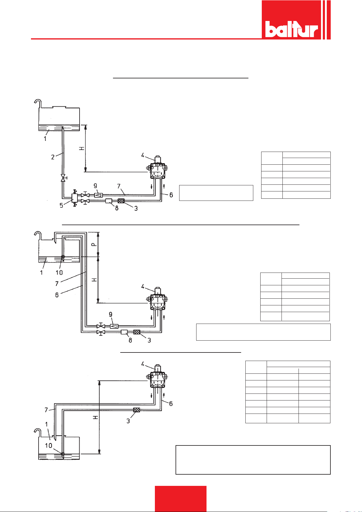
ESPAÑOL
TABLA TUBERÍAS PARA QUEMADORES MOD. BT 40 - 50 - 75 - 100 DSN - 4T CON COMBUSTIBLE DE
5° Y A 50° C (40° E A LA TEMPERATURA DE BOMBEO DE 5° C)
SISTEMA DE ALIMENTACIÓN POR GRAVEDAD
1 Depósito
2 Tubería de alimentación
3 Filtro de red
4 Bomba
5 Desgasicador
6 Tubo de aspiración
7 Tubo de retorno quemador
8 Dispositivo automático de corte con el quemador parado
9 Válvula unidireccional
H L Total
metros metros
EJE BOMBA
Presión máxima en
aspiración y retorno = 1 bar
Ø = 1"
1 31
2 35
2,5 35
3 35
SISTEMA EN CAÍDA CON ALIMENTACIÓN DESDE LA PARTE ALTA DEL DEPÓSITO
1 Depósito
3 Filtro de red
4 Bomba
6 Tubo de aspiración
7 Tubo de retorno
8 Dispositivo automático de corte
con el quemador parado
9 Válvula unidireccional
10 Válvula de pie
EJE BOMBA
Presión máxima en aspiración y retorno = 1 bar.
Cota P = 3,5 m. (máx.)
SISTEMA DE ALIMENTACIÓN EN ASPIRACIÓN
1 Depósito
EJE BOMBA
3 Filtro de red
4 Bomba
6 Tubo de aspiración
7 Tubo de retorno
10 Válvula de pie
H L Total
metros metros
Ø = 1"
1 31
2 35
2,5 35
3 35
H L Total metros
metros Ø = 1" Ø 1" 1/4
0,5 22 35
1 17 35
1,5 12 35
2 7 21
2,5 3 8
3 - 3,5 - -
NOTA: En el caso en que faltaran piezas en las
tuberías, atenerse a las normas vigentes.
H - Desnivel entre nivel mínimo en el depósito y eje bomba.
L - Longitud total de cada tubería comprendido el tramo
vertical. Para cada codo o válvula de cierre detraer 0,25 m.
12 / 40
0006080537_201610
Page 93

TABLA TUBERÍAS PARA QUEMADOR MODELO BT 120 DSN - 4T
CON COMBUSTIBLE DE 5° E A 50° C (40° E A LA TEMPERATURA DE BOMBEO DE 5° C)
SISTEMA DE ALIMENTACIÓN POR GRAVEDAD
1 Depósito
2 Tubería de alimentación
3 Filtro de red
4 Bomba
5 Desgasicador
6 Tubo de aspiración
7 Tubo de retorno quemador
8 Dispositivo automático de corte con el quemador parado
9 Válvula unidireccional
H L Total
metros metros
EJE BOMBA
Presión máxima en aspiración y retorno = 1 bar.
Ø = 1" 1/4
1 45
1,5 45
2 50
2,5 50
ESPAÑOL
SISTEMA EN CAÍDA CON ALIMENTACIÓN DESDE LA PARTE ALTA DEL DEPÓSITO
1 Depósito
3 Filtro de red
4 Bomba
6 Tubo de aspiración
7 Tubo de retorno
8 Dispositivo automático de corte con el quemador parado
9 Válvula unidireccional
10 Válvula de pie
EJE BOMBA
Presión máxima en aspiración y retorno = 1 bar.
Cota P = 3,5 m. (máx.)
H L Total
metros metros
Ø = 1" 1/4
1 45
1,5 45
2 50
2,5 50
SISTEMA DE ALIMENTACIÓN EN ASPIRACIÓN
H L Total metros
metros Ø = 1" 1/4
Ø 1" 1/2
0,5 35 40
1 30 35
1,5 26 35
2 13 25
2,5 5 10
3 - 3,5 - -
EJE BOMBA
NOTA: En el caso en que faltaran piezas en las tuberías, atenerse a las normas
vigentes.
1 Depósito
3 Filtro de red
4 Bomba
6 Tubo de aspiración
7 Tubo de retorno
10 Válvula de pie
H - Desnivel entre nivel mínimo en el depósito y eje bomba.
L -
Longitud total de cada tubería comprendido el tramo
vertical. Para cada codo o válvula de cierre detraer 0,25
m.
13 / 40
0006080537_201610
Page 94
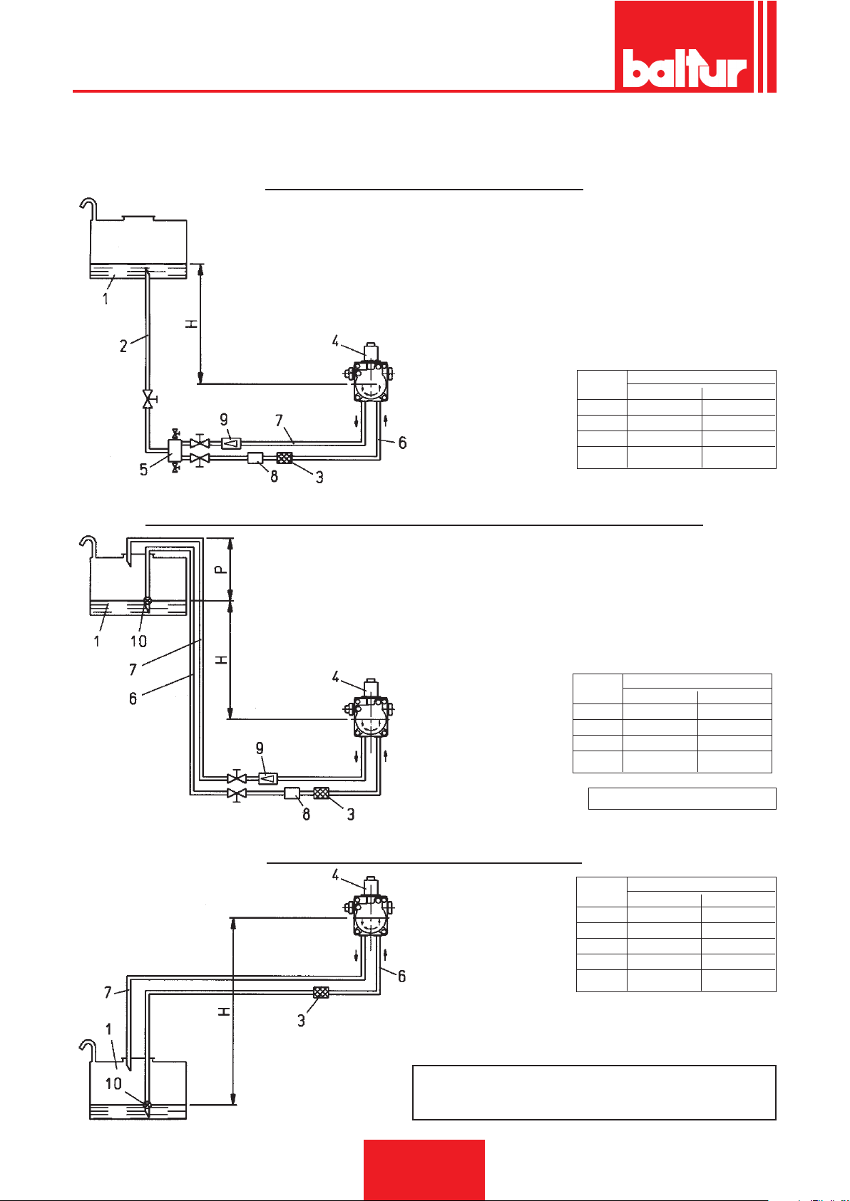
ESPAÑOL
TABLA TUBERÍAS PARA QUEMADORES MOD. BT 180 DSN - BT 250 DSN
CON COMBUSTIBLE DE 5° E a 50° C (40° E A LA TEMPERATURA DE BOMBEO DE 5° C)
SISTEMA DE ALIMENTACIÓN POR GRAVEDAD
1 Depósito
2 Tubería de alimentación
3 Filtro de red
4 Bomba
5 Desgasicador
6 Tubo de aspiración
7 Tubo de retorno quemador
8 Dispositivo automático de corte con el quemador parado
9 Válvula unidireccional
EJE BOMBA
H L Total metros
metros Ø = 1" 1/2 Øi. 41 mm
1 35 35
1,5 40 40
2 50 50
2,5 50 50
SISTEMA EN CAÍDA CON ALIMENTACIÓN DESDE LA PARTE ALTA DEL DEPÓSITO
1 Depósito
3 Filtro de red
4 Bomba
6 Tubo de aspiración
7 Tubo de retorno
8 Dispositivo automático de corte con el quemador parado
9 Válvula unidireccional
10 Válvula de pie
H L Total metros
EJE BOMBA
metros Ø = 1" 1/2 Øi. 41 mm
1 35 35
1,5 40 40
2 50 50
2,5 50 50
SISTEMA DE ALIMENTACIÓN EN ASPIRACIÓN
1 Depósito
EJE BOMBA
0006080537_201610
3 Filtro de red
4 Bomba
6 Tubo de aspiración
7 Tubo de retorno
10 Válvula de pie
H - Desnivel entre nivel mínimo en el depósito y eje bomba.
L -
Longitud total de cada tubería comprendido el tramo
vertical. Para cada codo o válvula de cierre detraer 0,25
14 / 40
Cota P = 3,5 m. (máx.)
H L Total metros
metros Ø = 1" 1/2 Øi. 41 mm
0,5 25 25
1 20 20
1,5 15 15
2 10 10
2,5 5 5
NOTA: En el caso en que faltaran piezas
en las tuberías, atenerse a las normas
vigentes.
m.
Page 95
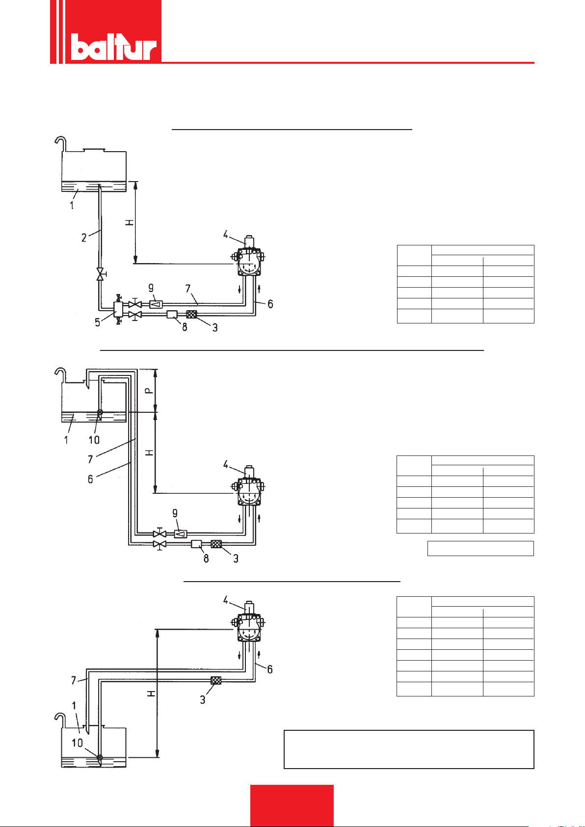
ESPAÑOL
TABLA TUBERÍAS PARA QUEMADORES MOD. BT 300 DSN - BT 350 DSN
CON COMBUSTIBLE DE 5° E a 50° C (40° E A LA TEMPERATURA DE BOMBEO DE 5° C)
SISTEMA DE ALIMENTACIÓN POR GRAVEDAD
1 Depósito
2 Tubería de alimentación
3 Filtro de red
4 Bomba
5 Desgasicador
6 Tubo de aspiración
7 Tubo de retorno quemador
8 Dispositivo automático de corte con el quemador parado
9 Válvula unidireccional
EJE BOMBA
H L Total metros
metros Ø = 1" 1/2 Øi. 41 mm
1 30 30
1,5 35 35
2 40 40
2,5 45 45
3 50 50
SISTEMA EN CAÍDA CON ALIMENTACIÓN DESDE LA PARTE ALTA DEL DEPÓSITO
1 Depósito
3 Filtro de red
4 Bomba
6 Tubo de aspiración
7 Tubo de retorno
8 Dispositivo automático de corte con el quemador parado
9 Válvula unidireccional
10 Válvula de pie
H L Total metros
EJE BOMBA
metros Ø = 1" 1/2 Øi. 41 mm
1 30 30
1,5 35 35
2 40 40
2,5 45 45
3 50 50
SISTEMA DE ALIMENTACIÓN EN ASPIRACIÓN
1 Depósito
EJE BOMBA
0006080537_201610
3 Filtro de red
4 Bomba
6 Tubo de aspiración
7 Tubo de retorno
10 Válvula de pie
NOTA: En el caso en que faltaran piezas en las tuberías,
atenerse a las normas vigentes.
H - Desnivel entre nivel mínimo en el depósito y eje bomba.
L -
Longitud total de cada tubería comprendido el tramo
vertical. Para cada codo o válvula de cierre detraer 0,25
15 / 40
Cota P = 3,5 m. (máx.)
H L Total metros
metros Ø = 1" 1/2 Øi. 41 mm
0,5 25 25
1 20 20
1,5 15 15
2 8 8
2,5 3 3
3 – –
3,5 – –
m.
Page 96
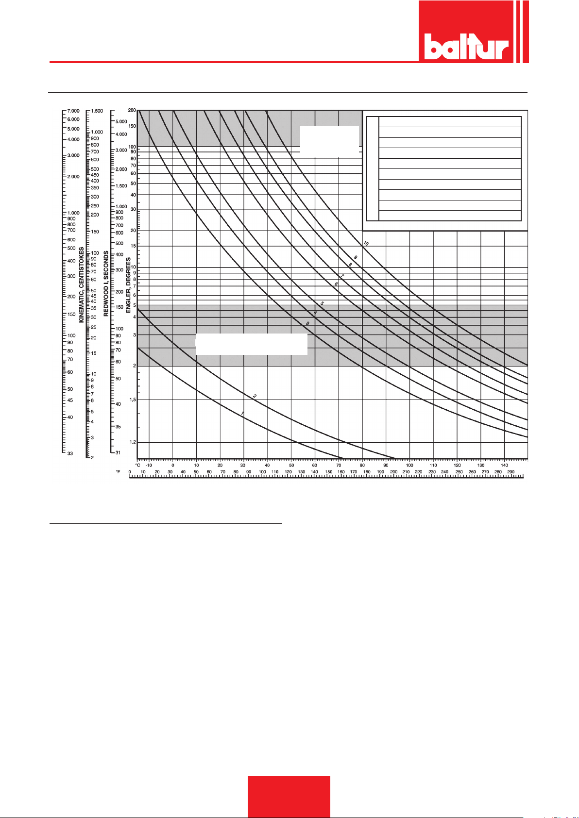
ESPAÑOL
DIAGRAMA DE VISCOSIDAD - TEMPERATURAS
VISCOSIDAD
Límite de
bombeo
1 GASÓLEO
2 EXTRA FLUIDO
3 FLUIDO 3/5
4 FLUIDO 5/7
5 DENSO 8
6 DENSO 15 - 20
CURVA
7 DENSO VISCOSIDAD 24° ENGLER A 50° C
8 DENSO VISCOSIDAD 35° ENGLER A 50° C
9 DENSO VISCOSIDAD 50° ENGLER A 50° C
10 DENSO VISCOSIDAD 85° ENGLER A 50° C
Campo de viscosidad
para la pulverización
TEMPERATURA
BOMBA AUXILIAR (VER 8511/6 - 8513/7)
En algunos casos (de distancia o desnivel excesivos o
bien viscosidad elevada o en todo caso si se utilizan los
quemadores vers. "D" denso) es necesario realizar la
instalación con un circuito de alimentación de "anillo",
con bomba auxiliar, evitando por tanto la conexión directa
de la bomba del quemador al depósito.
En este caso la bomba auxiliar se puede poner en mar-
cha cuando se enciende el quemador y parar cuando
el mismo se detiene.
La conexión eléctrica de la bomba auxiliar se realiza
conectando la bobina (230V) que manda el telerruptor
de la bomba misma, a los bornes "N" (regleta de bornes entrada línea del equipo) y "L1" (aguas abajo del
telerruptor del motor):
Se recomienda seguir siempre las indicaciones men-
cionadas a continuación:
• instalar la bomba auxiliar lo más cerca posible del líquido que
se debe aspirar
• la altura debe ser adecuada a la instalación en cuestión
• se aconseja un caudal por lo menos igual al caudal de la bomba
del quemador
• la dimensión de las tuberías de conexión debe ser en función
del caudal de la bomba auxiliar
• evitar absolutamente la conexión eléctrica directa de la bomba
auxiliar al telerruptor del motor del quemador.
16 / 40
0006080537_201610
Page 97
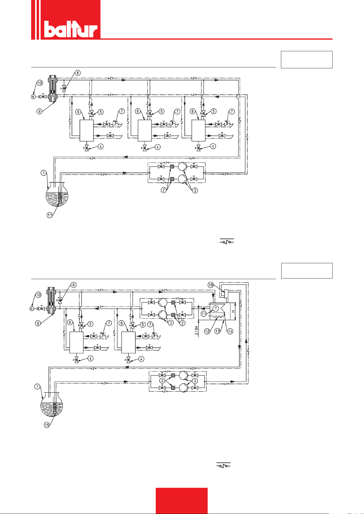
ESPAÑOL
ESQUEMA HIDRÁULICO GENERAL QUEMADORES DE DOS LLAMAS O MODULANTES QUE FUNCIONAN
CON ACEITE C. (MÁX. 15° E A 50° C)
NOTA: Los depósitos de recu-
peración de combustible
(diámetro: 150 mm; altura:
400 mm) se deben instalar
lo más cerca posible del
quemador, a una altura de
al menos 0,5 m por encima
de la bomba.
7 VÁLVULA ANTIRRETORNO
1 DEPÓSITO PRINCIPAL
2 FILTRO
3 BOMBA DE CIRCULACIÓN
4 DESAGÜE AGUA E INSTALACIÓN
5 DESCARGA AIRE-GAS NORMALMENTE CERRADA
6 DEPÓSITO PARA RECUPERACIÓN DEL
COMBUSTIBLE Y DESGASIFICADOR
8 BY-PASS (NORMALMENTE CERRADO)
9 REGULADOR DE PRESIÓN REGULABLE
ENTRE 0,5 - 2 BARES
10 MANÓMETRO (0-4 BARES)
11 SERPENTÍN DE CALENTAMIENTO ACEITE
COMBUSTIBLE, DE VAPOR O AGUA CALIENTE
CABLE ELÉCTRICO CALENTADOR (SI ES
NECESARIO)
N° BT 8511/6
ESQUEMA HIDRÁULICO GENERAL PARA VARIOS QUEMADORES DE DOS LLAMAS O MODULANTES
QUE UTILIZAN ACEITE C. DENSO (MÁX 50° E A 50° C) CON CALENTADOR AUXILIAR
NOTA: Los depósitos de recu-
peración de combustible
(diámetro: 150 mm; altura:
400 mm) se deben instalar
lo más cerca posible del
quemador, a una altura de
al menos 0,5 m por encima
de la bomba.
1 TANQUE PRINCIPAL
2 FILTRO
3 BOMBA DE CIRCULACIÓN
4 DESAGÜE AGUA E INSTALACIÓN
5 DESCARGA AIRE-GAS NORMALMENTE CERRADA
6 DEPÓSITO PARA RECUPERACIÓN DEL COMBUSTIBLE
Y DESGASIFICADOR
7 VÁLVULA ANTIRRETORNO
6 BY-PASS (NORMALMENTE CERRADO)
9 REGULADOR DE PRESIÓN REGULABLE ENTRE 0,5 - 2
BARES
10 MANÓMETRO (0 - 4 BARES)
11 TERMÓMETRO
12 RESISTENCIA
13 CALENTADOR AUXILIAR
14 SERPENTÍN DE VAPOR O AGUA CALIENTE
PARA CALENTAMIENTO ACEITE
15 SERPENTÍN DE CALENTAMIENTO ACEITE
COMBUSTIBLE, DE VAPOR O AGUA CALIENTE
16 RECIPIENTE DIÁMETRO 100MM ALTURA 300MM
CABLE ELÉCTRICO CALENTADOR (SI ES
NECESARIO)
N° BT 8513/7
17 / 40
0006080537_201610
Page 98

ESPAÑOL
PRIMER LLENADO TUBERÍA
Después de haber controlado que los tapones de protección situados dentro de las conexiones de la bomba
hayan sido quitados, se procede se la siguiente forma:
1) Colocar el interruptor del quemador en la posición "0".
Esta operación sirve para evitar el encendido automático del quemador y sobre todo, impide la activación de
las resistencias que funcionando con el depósito vacío se podrían quemar.
2) Asegurarse, si el quemador es trifásico, de que el motor gire hacia la izquierda, mirando el quemador del lado
de la bomba. La dirección de rotación se puede ver mirando el sentido de rotación del ventilador a través
del indicador situado en la parte trasera de la rosca. Para poner en marcha el motor, cerrar manualmente
el telerruptor (presionando en la parte móvil) por algunos segundos y observar el sentido de rotación del
ventilador. Si fuera necesario invertir el sentido de rotación, cambiar de lugar dos bornes de entrada de la
línea (L1 - L2 - L3).
Nota: Esperar, para establecer con seguridad el sentido de rotación, a que el ventilador gire muy lentamente
ya que es posible una interpretación errónea del sentido de rotación.
3) Desconectar si ya han sido conectados, los tubos exibles de la tubería de aspiración y de la de retorno.
4) Sumergir el extremo del tubo exible de aspiración en un recipiente con aceite lubricante o aceite combustible
(no se deben usar productos de baja viscosidad como el gasóleo, el petróleo, la gasolina, el queroseno, etc.).
5) Presionar ahora en la parte móvil del telerruptor del motor para poner en marcha el motor y por consiguiente, la
bomba.. Esperar hasta que la bomba haya aspirado una cantidad de lubricante igual a 1 ó 2 vasos, luego detener.
Esta operación se efectúa para evitar el funcionamiento en seco de la bomba y aumentar la fuerza de as-
piración.
Nota Las bombas que trabajan a 2800 vueltas no deben trabajar en seco bajo ningún concepto o, de lo
contrario, se bloquearán en muy poco tiempo (agarrotamiento).
6) Conectar ahora el exible al tubo de aspiración y abrir todas las válvulas de llave colocadas en este tubo así
como cualquier otro elemento que corte el paso del combustible
7) Presionar ahora en la parte móvil del telerruptor del motor para poner en marcha la bomba que aspirará
el combustible del tanque. Cuando el combustible saldrá del tubo de retorno (aún no conectado) soltar el
telerruptor.
Nota: Si la tubería es larga, puede ser necesario purgar el aire por el tapón correspondiente, si la bomba no
cuenta con éste, quitar el tapón de la conexión del manómetro. En este caso, si el combustible sale
por el oricio de conexión del manómetro es necesario interrumpir la operación y volver a poner el
tapón.. Reanudar por tanto la operación de carga hasta que se haya llenado el depósito (el depósito
del precalentador está lleno cuando se ve salir el combustible por el tubo exible de retorno no conectado todavía).
8) Conectar el tubo exible de retorno con la tubería y abrir las llaves situadas en este tubo. El quemador está
listo para el encendido.
DESCRIPCIÓN DEL FUNCIONAMIENTO
NOTA: Los quemadores de la versión "D" (denso) se proporcionan con la resistencia auxiliar para la bomba, para
el grupo pulverizador y para las dos electroválvulas, y el ltro de la línea está precalentado.
Al cerrar el interruptor en el quemador se activa el telerruptor de las resistencias (si el termostato correspondiente
lo permite). La tensión llega al telerruptor de las resistencias a través del contacto del termostato de ajuste. Las
resistencias activas calientan el aceite combustible en el depósito precalentador. Cuando la temperatura del
aceite ha alcanzado el valor suciente, se activa el termostato de mínima y, si los otros termostatos (ajuste y
seguridad) lo permiten, la corriente llega al equipo y activa, según el programa preestablecido, los dispositivos
que componen el quemador. La introducción del transformador de encendido se hace simultáneamente con la
del motor del quemador (utilizando el aparato OR 3/B), el transformador se introduce algunos segundos después
con el aparato LAL 1.24. El motor activa la rotación del ventilador, que realiza la preventilación con aire en la
cámara de combustión, y al mismo tiempo, el funcionamiento de la bomba hace que el aceite caliente circule
en los conductos, con expulsión del aceite frío y del posible gas a través del retorno. Esta fase de "prebarrido" y
"preventilación" termina con el cierre de la electroválvula n.º 7 (abierta en la posición de reposo) que interrumpe
la libre descarga del aceite hacia el tanque. Después del cierre de la electroválvula aumenta la presión en los
conductos de impulsión.
18 / 40
0006080537_201610
Page 99

ESPAÑOL
NOTA: El ltro de red del precalentador incorpora una válvula de muelle (antigás) que se abre permitiendo que
el combustible uya hasta alcanzar una presión de aprox. 2 ÷ 2,5 bar. Esta válvula debe mantener el precalentador en presión (aunque sea poca) incluso con el quemador apagado para reducir y posiblemente
evitar la formación de gas con aceite caliente y el quemador apagado. La pérdida de presión debida a esta
válvula "antigás" es de aprox. 2 ÷ 2,5 bar y por tanto se debe regular la presión de pulverización (presión
bomba) a un valor superior para compensar esta reducción de presión. En práctica se debe regular la presión de la bomba a 27 bar. Cuando la presión alcanza un valor de 16 bar, se abre el dispositivo de cierre
de la boquilla situada en el grupo pulverizador, para permitir que el aceite llegue a la boquilla de la primera
llama y de allí salga a la cámara de combustión namente pulverizado. La presión se estabiliza en aprox.
27 bar porque el regulador de presión de la bomba ha sido calibrado a este valor. En cuanto el aceite pulverizado sale de la boquilla, la descarga de los electrodos ya presente lo incendia. Durante el encendido
de la primera llama la compuerta del aire es mantenida por el servomotor en la posición establecida, en
función de la cantidad de combustible quemado. Si la llama aparece normalmente, se supera la posición
de bloqueo, se desconecta el transformador de encendido y se activa la electroválvula de la segunda llama
n.º 8 (cerrada en reposo). La abertura de la válvula de segunda etapa permite que el combustible llegue
al dispositivo de cierre de la boquilla segunda etapa n.° 4/1 a una presión de 25 bar. La presión de 27 - 2
= 25 bar, actúa en el dispositivo de cierre boquilla de la 2° etapa que, hasta una presión de 16 bar, impide
el aujo del combustible a la segunda boquilla Este dispositivo se abre gracias a la presión y a este punto
comienza a funcionar también la segunda boquilla. La presión de 25 bar actúa ahora en las dos boquillas.
Para medir la presión efectiva en el grupo pulverizador y por tanto en las boquillas, se recomienda conectar
el manómetro con la conexión especíca del ltro depósito (ver el dibujo 0002932230).
NOTA: De todo lo expuesto resulta evidente que la elección de las boquillas, en función del caudal total (2 boquillas
en funcionamiento) deseado, debe ser efectuada teniendo en cuenta los valores de caudal correspondientes a la presión de trabajo de 25 bar. Se debe tener en cuenta que cuando el quemador trabaja con solo
la primera etapa activa, el suministro de combustible sale por una sola boquilla, en función de la presión
de 25 bar. Obviamente la relación entre la primera y la segunda llama se puede variar, dentro de amplios
límites, cambiando las boquillas. Para obtener un buen funcionamiento, el suministro de combustible con
la primera etapa no debería ser inferior al caudal mínimo indicado (indicado en la placa de características)
para el modelo especíco. Un caudal inferior podría dicultar el encendido y la combustión con solo la
primera etapa podría no ser buena.
NOTA: algunos modelos de quemadores utilizan tres boquillas (ver dibujo n.º 0002900564) en este caso las
boquillas de la segunda etapa son dos y ambas a una presión de 25 bar.
Del momento en que aparece la llama en la cámara de combustión, el quemador es mandado y controlado por
la fotorresistencia y por los termostatos. Cuando la temperatura o la presión alcanza el valor de calibración del
termostato o presostato de ejercicio, la activación del mismo determina la parada del quemador.
El equipo vuelve a funcionar automáticamente cuando el valor de la temperatura o de la presión baja del valor
necesario. Si por alguna razón durante el funcionamiento faltara la llama, se activa inmediatamente (en un
segundo) la fotorresistencia que, interrumpiendo la alimentación del relé homónimo, determina la abertura y
por tanto la desconexión de la electroválvula "7" de circulación. Ésta, abriéndose, descarga rápidamente la
presión existente y el rociado de aceite pulverizado es interceptado por el cierre automático de los dispositivos
de cierre boquilla del grupo pulverizador, cuando la presión desciende por debajo del valor de programación.
En este caso, (con el equipo mod. OR 3/B) la fase de encendido se repite automáticamente y, si la primera llama
vuelve a encenderse normalmente, el funcionamiento del quemador recomienza normalmente, de lo contrario
(llama irregular o totalmente ausente) el equipo se bloquea automáticamente. Si se utiliza el equipo modelo LAL
1.25, en caso de falta de llama, el quemador se bloquea sin intentar un segundo encendido. Si se interrumpe el
programa (falta de tensión, operación manual, activación del termostato, etc...) durante la fase de prebarrido, el
programador regresa a la posición inicial y repite toda la fase de encendido del quemador.
CARACTERÍSTICAS DEL EQUIPO
Modelo Aparato y Tiempo de seguridad Tiempo de preventilación Post encendido Tiempo entre 1a
y
Quemador relativo programador en segundos en segundos en segundos 2a etapa
en segundos
BT 40 DSN - 4T
BT 55 DSN - 4T OR 3/B 5 30 5 5
BT 75 DSN - 4T
BT 100 DSN - 4T
BT 120 DSN - 4T
BT 180 DSN - 4T
BT 250 DSN - 4T LAL 1.25 5 22,5 15 7,5
BT 300 DSN - 4T
BT 350 DSN - 4T
Relé cíclico
0006080537_201610
19 / 40
Page 100

ESPAÑOL
ENCENDIDO Y AJUSTE
Antes del encendido es necesario comprobar que:
a) las conexiones con la línea de alimentación, con los termostatos o presostatos, hayan sido efectuadas según
el esquema eléctrico del equipo;
b) haya combustible en el tanque y agua caliente en la caldera;
c) todas las válvulas en la tubería de aspiración y de retorno del aceite combustible estén abiertas y también
cualquier otro dispositivo de cierre del combustible;
d) la descarga de los productos de la combustión pueda hacerse correctamente (compuertas de la caldera y de
la chimenea abiertas);
e) comprobar que el cabezal del quemador penetre en la cámara de combustión según las indicaciones del
fabricante de la caldera. Para poder respetar esta disposición el quemador debe estar provisto de brida de
conexión de la caldera, deslizante con respecto al cabezal de combustión.
f) Las boquillas instaladas en el quemador deben ser adecuadas para la potencia de la caldera y, si fuera nece-
sario, se deben sustituir con otras. En ningún caso la cantidad de combustible suministrado debe ser superior
a la máxima requerida por la caldera y a la máxima admitida por el quemador. Es importante recordar que el
cabezal de combustión ha sido diseñado para boquillas con ángulo de rociado de 45°.
Nota: Para lograr un buen encendido y una buena combustión con la única primera llama es necesario que
el suministro del combustible no sea sensiblemente inferior al caudal mínimo (indicado en la placa)
para el quemador especíco.
PARA EL ENCENDIDO PROCEDER DEL MODO SIGUIENTE:
Nota: El quemador está equipado con un interruptor para pasar manualmente de la 1a a la 2a etapa.
1) Abrir el interruptor primera y segunda etapa para impedir la habilitación de la segunda etapa.
2) Abrir un poco la compuerta del aire para permitir el ujo de aire que se supone necesario para el funcio-
namiento del quemador en primera etapa, actuando en la leva que limita la carrera del servomotor para la
primera etapa (ver BT 8653/1 ó BT 8711/1 ), regular en una posición intermedia el dispositivo de regulación
del aire en el cabezal de combustión (ver más adelante, en el capítulo "Regulación del aire en el cabezal de
combustión").
3) Conectar el interruptor general y el de marcha/detención en el quemador. Con esta nueva operación se activan
enseguida las resistencias que calientan el aceite combustible, y al mismo tiempo, se enciende el indicador
amarillo correspondiente en el quemador.
4) El termostato de mínima se cierra cuando el combustible, contenido en el precalentador, alcanza la temperatura
a la cual ha sido regulado. El cierre del termostato de mínima determina, si los otros termostatos de caldera
están cerrados, la activación del equipo que conecta los componentes del quemador según el programa
preestablecido. El equipo se enciende como se describe en el capítulo “Descripción del funcionamiento”.
5) Cuando el quemador trabaja con la 1a llama, se regula el aire a la cantidad necesaria para asegurar una buena
combustión. Es preferible que la cantidad de aire para la primera llama sea ligeramente escasa para asegurar
un perfecto encendido incluso en los casos más laboriosos.
6) Una vez regulado el aire para la primera etapa, el quemador se para, cortando la corriente del interruptor
general, se conectan entre ellos los bornes del terminal de bornes del termostato de la 2a etapa y se coloca
el interruptor primera y segunda etapa en posición segunda etapa.
7) Se actúa en la leva que limita la carrera del servomotor de mando compuerta aire de la segunda etapa, ajustándola a la cantidad que se supone necesaria para el combustible que se debe quemar (ver BT 8653/1 ó BT
8711/1 ).
8) Se activa ahora nuevamente el aparato que se enciende y pasa automáticamente, según el programa establecido por el programador, a la 2a llama.
9) Cuando el quemador trabaja con la 2a llama, se regula el aire a la cantidad necesaria (a través de la leva
citada en el punto 7), para asegurar una buena combustión. El control de la combustión se debe ejecutar
con los instrumentos especícos. Si no se dispone de los instrumentos necesarios, basarse en el color
de la llama. Se recomienda regular la llama para que sea suave, de un color anaranjado claro, evitan-
do la llama roja con presencia de humo, así como la llama blanca con una cantidad exagerada de aire.
El regulador del aire debe estar en una posición que permita un porcentaje de anhídrido carbónico (CO2) en los
20 / 40
0006080537_201610
 Loading...