

Page 1
it
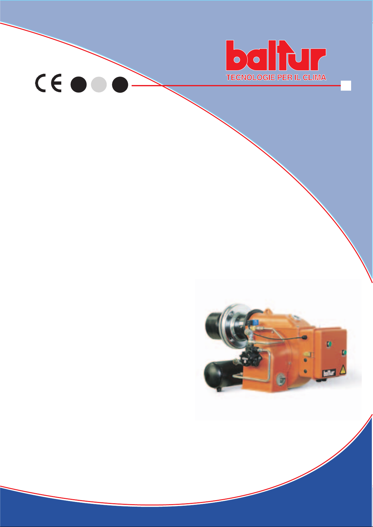
- Istruzioni per bruciatori modello
- Instruction for burners model
- Instrucciónes para quemadores modelos
en
sp
BT 15 N
BT 22 N
BT 35 N
Edizione / Edition / Ediciòn
2007/01
Cod. 98331
Page 2

Page 3

- Leggere attentamente le istruzioni prima di mettere in funzione il bruciatore o di eseguire
- I lavori sul bruciatore e sull’impianto devono essere eseguiti solo da personale qualifi cato.
- L’alimentazione elettrica dell’impianto deve essere disinserita prima di iniziare i lavori.
- Se i lavori non sono eseguiti correttamente si rischiano incidenti pericolosi.
- Read carefully the instructions before starting the burner and service it.
- The system electric feeding must be disconnected before starting working on it.
- If the works are not carried out correctly it is possible to cause dangerous accidents.
AL USUARIO PARA USAR CON SEGURIDAD EL QUEMADOR” que va con el manual de instruc-
- Lea atentamente las instrucciones antes de poner en funcionamento los quemadores
y efectuar las tareas de mantenimiento.
- Los trabajos que se efectúen al quemador y a la instalación deben ser efectuados sólamente por
- La alimentación eléctrica de la instalación se debe desconectar antes de iniciar los trabajos.
- Si los trabajos no son efectuados correctamente se corre el riesgo de que se produzcan accidentes
Page 4
Vicepresidente e Amministratore Delegato:
Administrador Delegado:
Dr. Riccardo Fava
We hereby declare under our own
BALTUR S.p.A.
Via Ferrarese 10 - 44042 CENTO (Ferrara) ITALIA
Tel. 051.684.37.11 Fax 051.685.75.27/28
(International Tel. ++39.051.684.37.11 - Fax ++39.051.683.06.86)
http://www.baltur.it - http://www.baltur.com - E-MAIL [email protected]
y han sido diseñados y ensayados según las Normas europeas:
Page 5

............................................................
................................................................................................
....................................................................
.........................................................
.................................................................................................................
.................................
...................................................................................
....................................................................................
...................................................................................
..................................................................................................................................
the burnersafely " 6
.........
.......................................................................................................
.................................................................................................................
.............................................................................................................
............................................................................................
.....................................................................
.........................................................................................................
PÁG. 34
ADVERTENCIAS DIRIGIDAS AL USUARIO PARA USAR EL QUEMADOR EN CONDICIONES
DE SEGURIDAD PRELIMINARES
..........................................................................................................................................
....................................................................................................................
.....................................
...........................................................
.....................................................................................................................
...................
.........................................................................................................
.........................................................................................
............................................................
.......................................................................................
Page 6

4 / 59
AVVERTENZE PER L’UTENTE
AVVERTENZE GENERALI
utilizzando esclusivamente ricambi originali. Il mancato rispetto di quanto sopra, può
fare effettuare da personale professionalmente qualifi cato la manutenzione periodica attenendosi alle indicazioni fornite dal costruttore.
forni o altri focolari simili, situati in luogo riparato dagli agenti atmosferici. Ogni altro uso é da considerarsi improprio e quindi pericoloso.
Disinserire l’alimentazione elettrica staccando il cavo di alimentazione dell’interruttore generale.
b)
Chiudere l’alimentazione del combustibile attraverso la valvola manuale di intercettazione e asportare i volantini di comando dalla loro sede.
Rendere innocue quelle parti che potrebbero essere potenziali fonti di pericolo.
Avvertenze particolari
a)
Tarare la portata di combustibile del bruciatore secondo la potenza richiesta dal generatore di calore.
Regolare la portata d’aria comburente per ottenere un valore di rendimento combustione almeno pari al minimo imposto dalle norme vigenti.
c)
Eseguire il controllo della combustione onde evitare la formazione di incombusti nocivi o inquinanti oltre i limiti consentiti dalle norme vigenti.
d)
Verifi care la funzionalità dei dispositivi di regolazione e di sicurezza.
e)
Verifi care la corretta funzionalità del condotto di evacuazione dei prodotti della combustione.
f)
Controllare al termine delle regolazioni che tutti i sistemi di bloccaggio meccanico dei dispositivi di regolazione siano ben serrati.
Accertarsi che nel locale caldaia siano presenti le istruzioni relative all’uso e manutenzione del bruciatore.
Page 7

AVVERTENZE PER L’UTENTE
ALIMENTAZIONE ELETTRICA
terra, eseguito come previsto dalle vigenti norme di sicurezza. E’ necessario verifi care questo fondamentale requisito di sicurezza. In caso
- non toccare l’apparecchio con parti del corpo bagnate o umide e/o a piedi umidi
- non tirare i cavi elettrici
- non lasciare esposto l’apparecchio ad agenti atmosferici (pioggia, sole, ecc.) a meno che non sia espressamente previsto.
- non permettere che l’apparecchio sia usato da bambini o da persone inesperte.
ALIMENTAZIONE CON GAS, GASOLIO, O ALTRI COMBUSTIBILI
Avvertenze generali
vigenti, poiché un’errata installazione può causare danni a persone, animali o cose, nei confronti dei quali il costruttore non può essere
il controllo della tenuta nel tratto interno ed esterno dei tubi di adduzione del combustibile;
la regolazione della portata del combustibile secondo la potenza richiesta al bruciatore;
che il bruciatore sia alimentato dal tipo di combustibile per il quale é predisposto;
che la pressione di alimentazione del combustibile sia compresa nei valori riportati in targhetta del bruciatore;
che l’impianto di alimentazione del combustibile sia dimensionato per la portata necessaria al bruciatore e che sia dotato di tutti i
dispositivi di sicurezza e controllo prescritti dalle norme vigenti.
Avvertenze particolari per l’uso del gas
che la linea di adduzione e la rampa siano conformi alle norme e prescrizioni vigenti.
b)
che tutte le connessioni gas siano a tenuta.
non azionare interruttori elettrici, il telefono e qualsiasi altro oggetto che possa provocare scintille;
aprire immediatamente porte e fi nestre per creare una corrente d’aria che purifi chi il locale;
chiudere i rubinetti del gas;
chiedere l’intervento di personale professionalmente qualifi cato.
Page 8

WARNING NOTES FOR THE USER
These warning notes are aimed at ensuring the safe use of the components of heating systems for civil use and the production of hot water.
They indicate how to act to avoid the essential safety of the components being compromised by incorrect or erroneous installation and by
when needed.
the term ‘qualifi ed technicians’ is meant persons that are competent in the fi eld of heating components for civil use and for the production
a) Switch off the electrical supply by disconnecting the power cable from the master switch.
b) Cut off the fuel supply using the shut-off valve and remove the control wheels from their position.
c) Render harmless any potentially dangerous parts.
f) Check at the end of the adjustments that all the adjustment devices mechanical securing systems are properly tightened.
Page 9

WARNING NOTES FOR THE USER
technicians, since the manufacturer will not be liable for any damage caused by a poor ground connection.
- do not touch the equipment with parts of the body that are wet or damp or with damp feet
- do not pull on electrical cables
- do not leave the equipment exposed to atmospheric agents (such as rain or sun etc.) unless there is express provision for this.
- do not allow the equipment to be used by children or inexpert persons.
that use electricity (pumps, burner, etc.).
a) that the feed line and the train comply with current law and regulations.
b) that all the gas connections are properly sealed.
a) do use any electrical switches, the telephone or any other object that could produce a spark;
b) immediately open doors and windows to create a current of air that will purify the room;
c) close the gas taps;
d) ask for the help of qualifi ed technicians.
fl ue. In the above situation, traditional fl ues (in terms of their diameter and heat insulation) may be suitable because the signifi cant cooling
there is soot at the point the exhaust reaches the atmosphere when burning light oil or heavy oil or the presence of condensate water along
the fl ue itself when gas is being burnt (methane, LPG, etc.). Flues connected to high effi ciency boilers and similar must therefore be of a size
Page 10

ADVERTENCIAS GENERALES
y depositarse en sitios destinados a dicha fi nalidad.
vigentes, que sean sufi cientes para obtener una combustión perfecta.
y explosivas.
a) Desconectar la alimentación eléctrica quitando el cable de alimentación del interruptor general.
b) Cerrar la alimentación del combustible por medio de la válvula de corte y quitar los volantes de mando de su alojamiento.
c) Hacer que sean inocuas las partes que podrían ser potenciales fuentes de peligro.
Advertencias particulares
f) Al fi nal de todas las regulaciones controlar que todos los sistemas de bloqueo mecánico de los dispositivos de regulación estén bien
ADVERTENCIAS DIRIGIDAS AL USUARIO PARA USAR EL
Page 11

ADVERTENCIAS DIRIGIDAS AL USUARIO PARA USAR EL
ALIMENTACIÓN ELÉCTRICA
fabricante no se hace responsable de los posibles daños causados por la falta de puesta a tierra de la instalación.
- no tocar el aparato con partes del cuerpo mojadas o húmedas y/o con los pies descalzos.
- no tirar de los cables eléctricos
- no dejar el aparato expuesto a agentes atmosféricos (lluvia, sol, etc.) de no ser que no esté expresamente previsto.
- no permitir que el aparato lo usen niños o personas inexpertas.
ALIMENTACIÓN CON GAS, GASÓLEO U OTROS COMBUSTIBLES
Advertencias generales
dispositivos de seguridad y control prescritos por las normas vigentes.
Advertencias particulares para el uso del gas
a) que la línea de abastecimiento de combustible y la rampa se ajusten a las normativas vigentes.
b) que todas las conexiones del gas sean estancas.
y aislamiento térmico) pueden no ser adecuadas para funcionar correctamente pues el enfriamiento que los productos de la combustión
forma agua de condensación a lo largo de la chimenea en cuestión, cuando se quema gas (metano, G.L.P., etc.). Según lo anteriormente
y aislamiento térmico) para su uso específi co para evitar el inconveniente arriba descrito.
Page 12
CARACTERISTICAS TECNICAS
MIN Kg/h
VISCOSITA’ COMBUSTIBILE / FUEL VISCOSITY /
VISCOSIDAD COMBUSTIBLE
kW
VOLT
kW
ACCESSORI A CORREDO - STANDARD ACCESSORIES
ABRAZADERA ELÁSTICA
Page 13
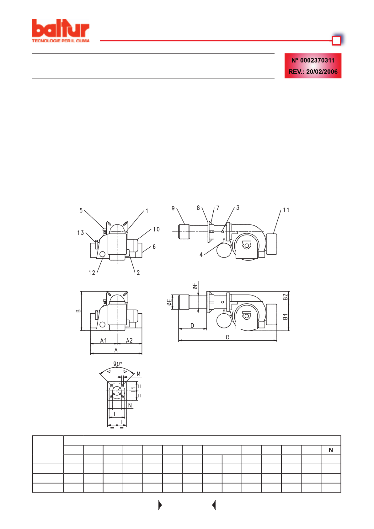
di combustione
4) Filtro preriscaldatore
4) Pre-heater fi lter
cabeza de combustión
4) Filtro precalentador
CARACTERISTICAS TECNICAS
AA1A2
BT 15N
475
475
BT 35N
400
Page 14
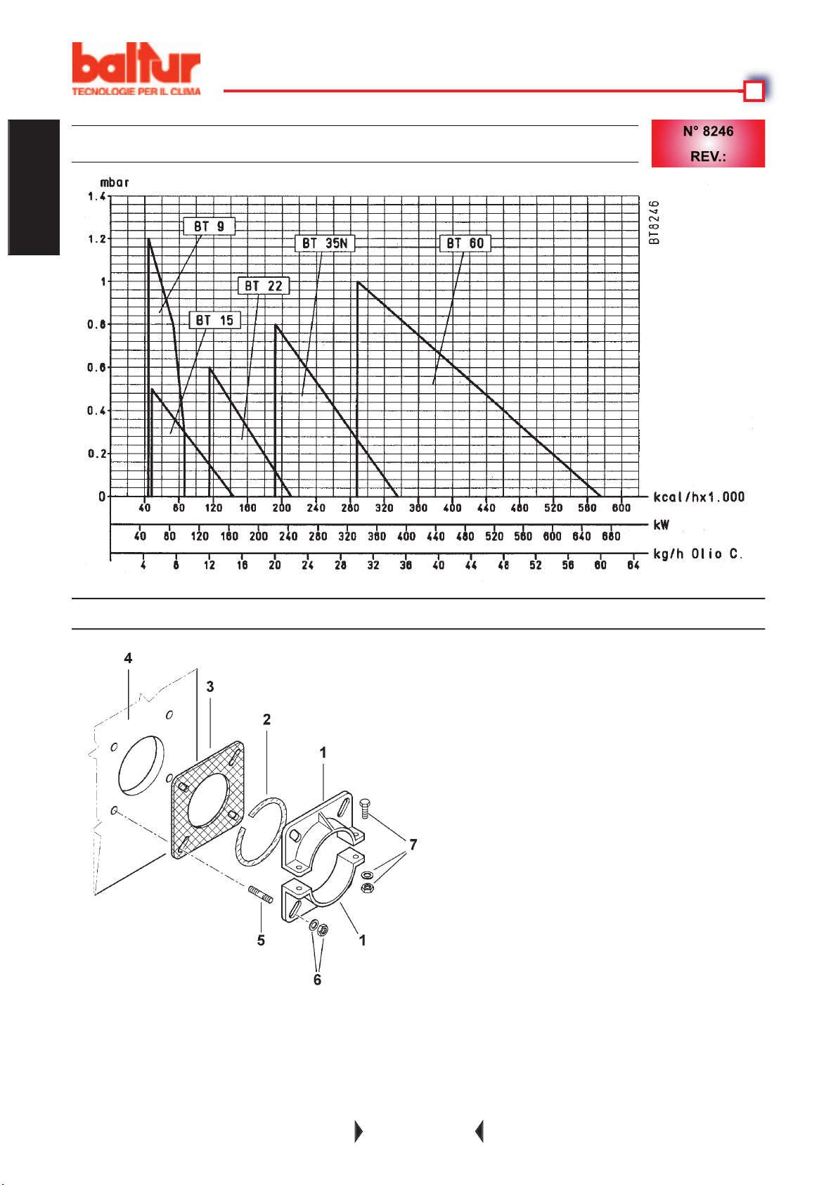
(fl ange di fi ssaggio in acciaio)
zione, della stessa, nel focolare (la profondi-
tà di penetrazione, della testa, deve essere
ITALIANO
4 - Piastra caldaia
Page 15

4) Le tubazioni del combustibile devono essere eseguite come da nostri schemi.
Accertarsi che la bocca del bruciatore penetri in camera di combustione come da disposizioni del costruttore
Accertarsi che la bocca del bruciatore penetri in camera di combustione come da disposizioni del costruttore
Assicurarsi che la linea elettrica a cui si vuole collegare l'apparecchio sia alimentata con valori di tensione e fre-
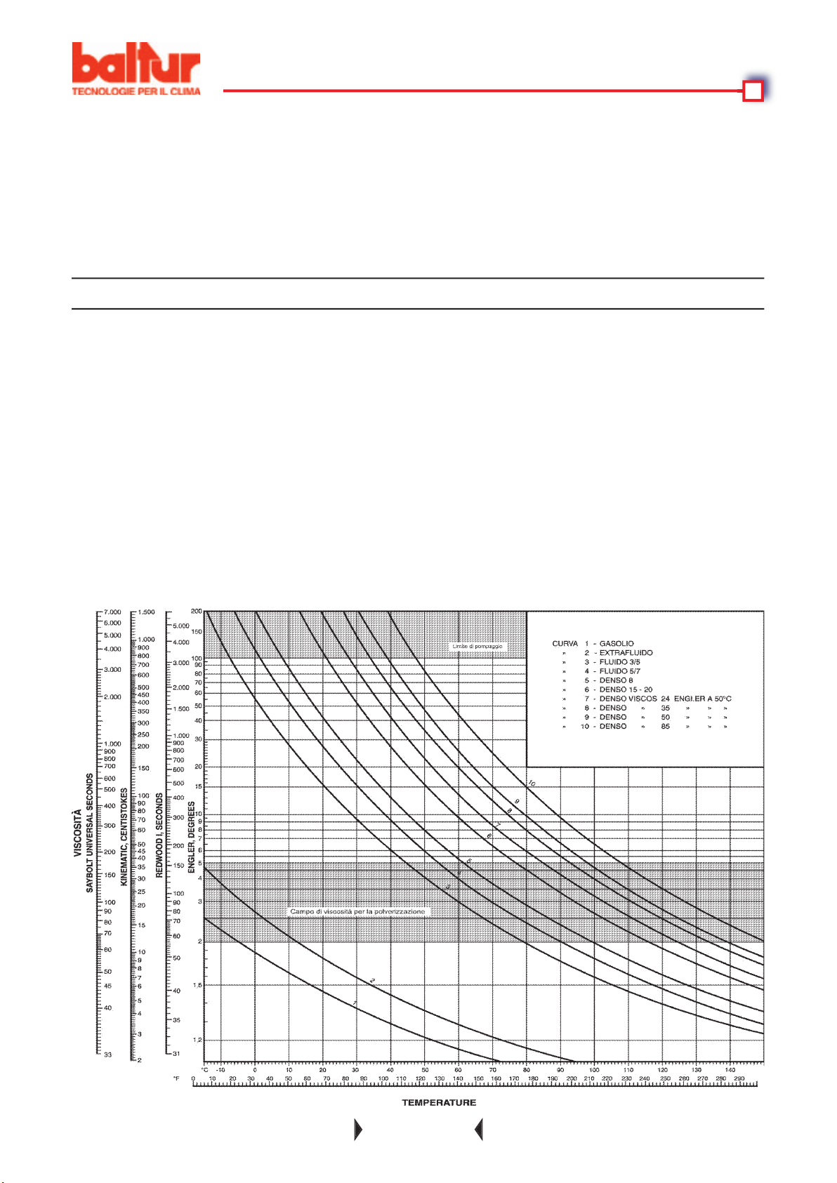
tabella relativa alle distanze e ai dislivelli e il diagramma viscosità - temperature).
Page 16
Page 17
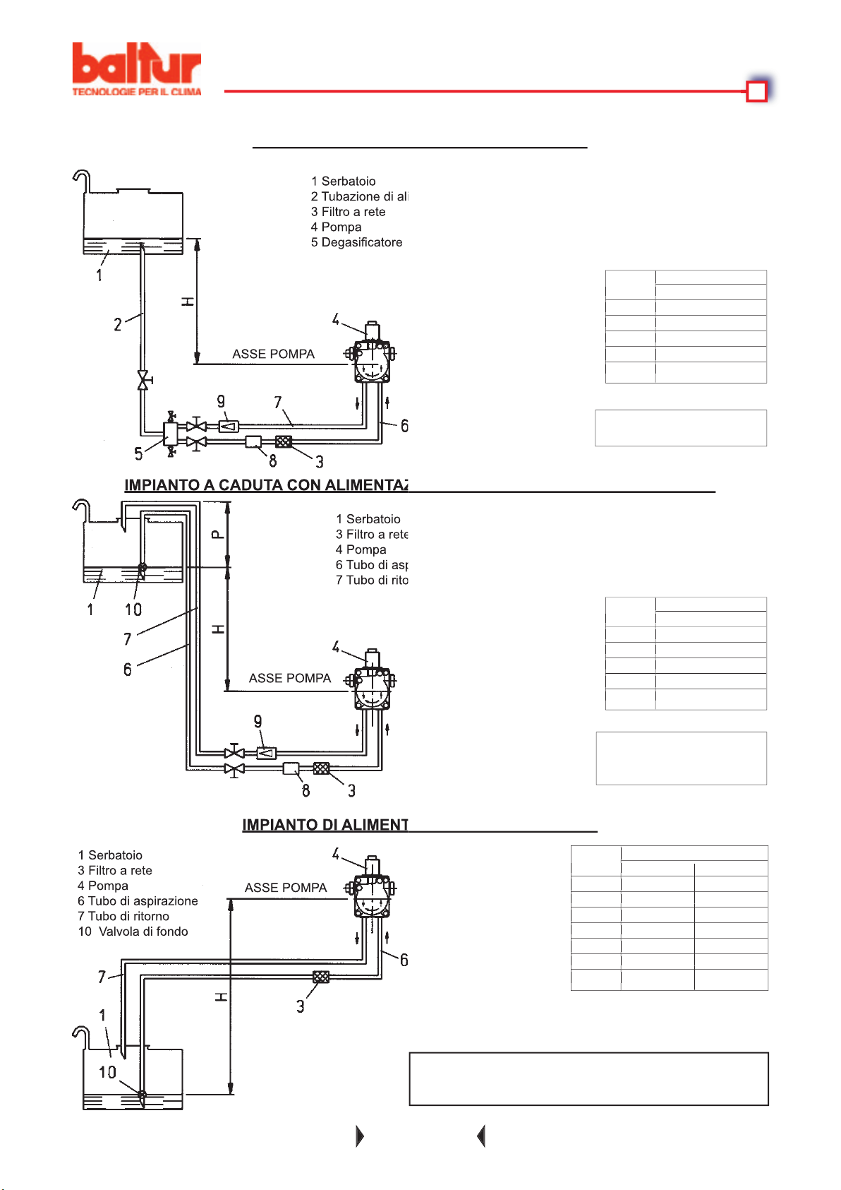
metri Ø = 1" Ø 1" 1/4
0,5 22 35
1 17 35
1,5 12 35
2 7 21
2,5 3 8
3 - -
3,5 - -
metri Ø = 1" Ø 1" 1/4
0,5 22 35
1 17 35
1,5 12 35
2 7 21
2,5 3 8
3 - -
3,5 - -
verticale. Per ogni gomito o saracinesca detrarre 0,25 m.
tubazioni attenersi alle norme vigenti.
metri metri
Ø = 1"
1 31
2 35
2,5 35
3 35
metri metri
Ø = 1"
1 31
2 35
2,5 35
3 35
metri metri
Ø = 1"
1 31
2 35
2,5 35
3 35
metri metri
Ø = 1"
1 31
2 35
2,5 35
3 35
4 Pompa
4 Pompa
a bruciatore fermo
a bruciatore fermo
4 Pompa
ASSE POMPA
ASSE POMPA
ASSE POMPA
Page 18
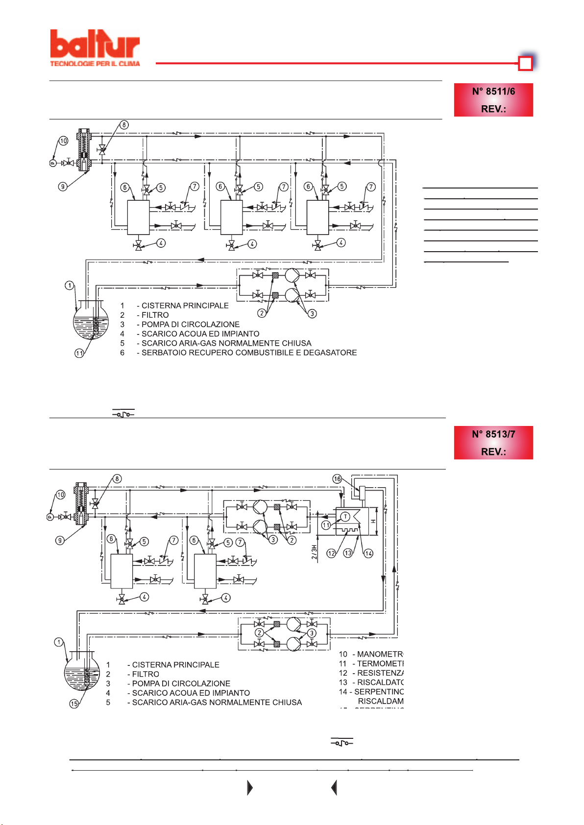
1 - CISTERNA PRINCIPALE
2 - FILTRO
3 - POMPA DI CIRCOLAZIONE
4 - SCARICO ACOUA ED IMPIANTO
5 - SCARICO ARIA-GAS NORMALMENTE CHIUSA
CAVO ELETTRICO SCALDANTE (SE NECESSARIO)
CAVO ELETTRICO SCALDANTE (SE NECESSARIO)
4 - SCARICO ACOUA ED IMPIANTO
CAVO ELETTRICO SCALDANTE (SE NECESSARIO)
CAVO ELETTRICO SCALDANTE (SE NECESSARIO)
Page 19

Alla chiusura del termostato di minima, se gli altri termostati (regolazione e sicurezza) lo consentono, la corrente
trova nel gruppo polverizzatore e l'olio raggiunge l'ugello dal quale esce in camera di combustione fi nemente
fi ltro del preriscaldatore.
Appena l'olio polverizzato esce dall'ugello, viene incendiato dalla scarica agli elettrodi che è già presente dalla
ticamente quando il valore della temperatura o pressione si sia abbassato della quantità necessaria.
fotoresistenza interrompendo l'alimentazione dell'elettrovalvola del lavaggio che, aprendosi, scarica rapidamente
termostato, ecc.) l'apparecchiatura ripete automaticamente dall'inizio tutta la fase di accensione del bruciatore.
termostato secondo necessità; la relativa segnalazione è data dalla lampada gialla sul bruciatore.
Apparecchiatura
Page 20
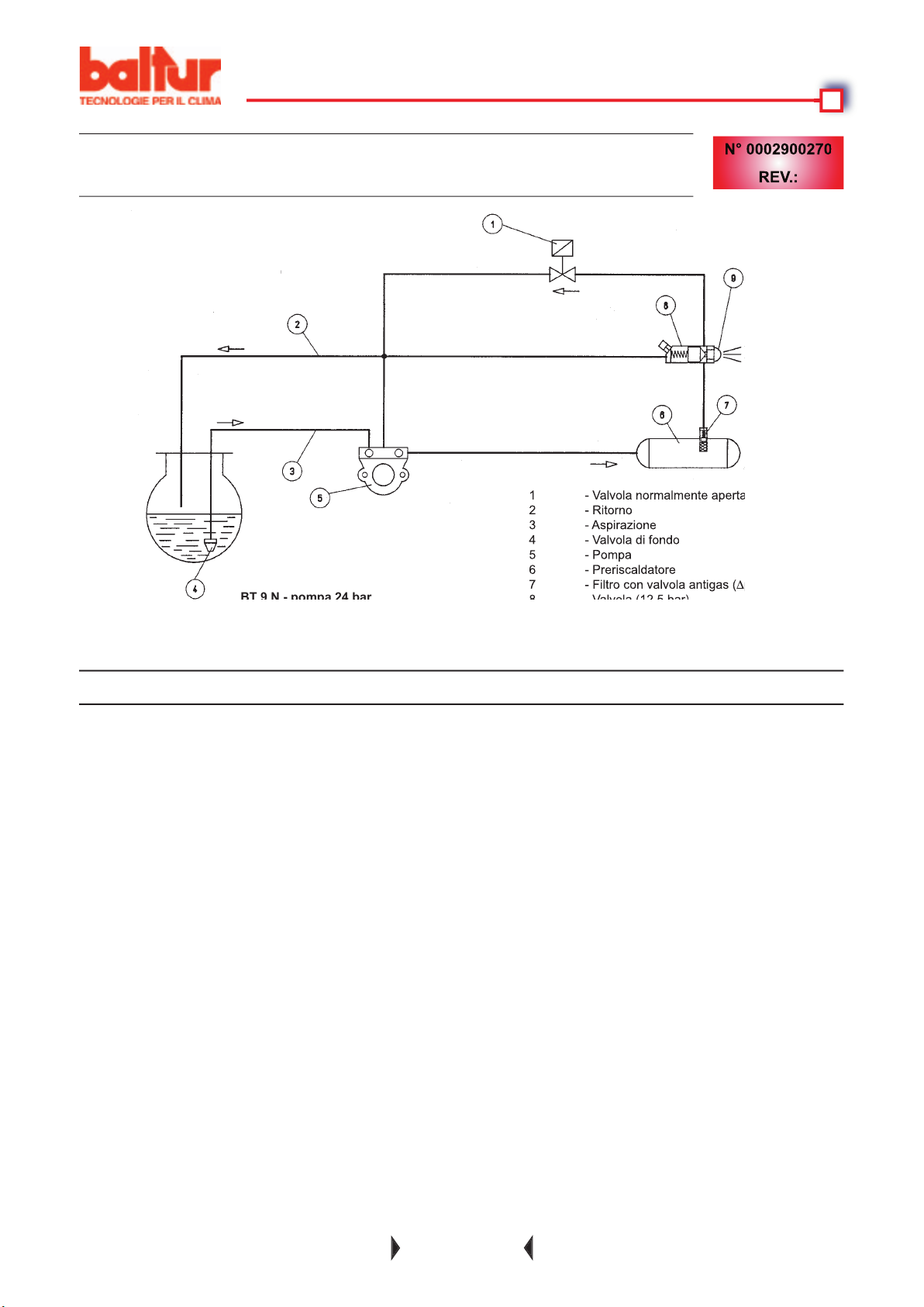
Asportati i tappi di protezione in plastica posti entro gli attacchi della pompa, procedere come segue:
vuoto, potrebbero bruciare.
Attenzione:
Attendere, per apprezzare con sicurezza il senso di rotazione, che la ventola giri molto lentamente
4) Immergere l'estremità del tubo fl essibile di aspirazione in un recipiente contenente olio lubrifi cante o olio
4 - Valvola di fondo
∆
Page 21

ACCENSIONE E REGOLAZIONE
tore.
4) Quando il bruciatore è in funzione si provvede a regolare l'aria, operando come descritto al punto 1, della
2
fumi, variabile da un minimo del 10% ad un massimo del 13 % con un numero di fumo non superiore a
viene effettuata dal costruttore su valori che possono essere inaccettabili per il caso singolo; occorre quindi,
formazione di gas nel preriscaldatore, ecc.). Se è necessario variare questi valori in più o in meno, tenendo
superiore a 2° E. (Vedi a titolo
Page 22

Acceso il bruciatore occorre controllare i dispositivi di sicurezza (fotoresistenza, blocco, termostati).
fi amma. Il blocco comporta l'arresto immediato del bruciatore e l'accensione della lampada rossa.
trollo (Termometro di caldaia); in caso contrario modifi care la taratura della scala del termostato facendola
fi amma. Può essere indispensabile avere un'elevata pressione d'aria a monte del disco, per evitare pulsazioni di
fi amma, questa condizione è praticamente indispensabile quando il bruciatore lavora su focolare pressurizzato e/o
dietro al disco un valore decisamente
tale da richiedere una sensibile apertura della serranda aria che regola il fl usso all'aspirazione del ventilatore
si provvede a correggere la posizione del dispositivo che
Page 23

tubazione, ecc.), in questi casi, se sbloccato, il bruciatore si avvia regolarmente.
Può però essere necessario effettuare la suddetta operazione con maggior frequenza.
Page 24

fi amma. (Lampada rossa accesa)
fi amma (lampada rossa accesa).
zare combustibile (lampada rossa acce-
4) Disco o bocca sporchi
4) Trasformatore di accensione
4) Eccesso di aria di combustione
pompa
4) Manca olio combustibile in cisterna
tempo massimo concesso dal program-
4) Pulirli
4) Sostituirlo
4) Ridurre l'aria di combustione
4) Effettuare il riempimento
tuire il gruppo polverizzatore
fornitrice dell'energia elettrica
Page 25

faville
4) Filtro sgrossatore sporco
zione
4) Potenza complessiva delle resistenze
eseguita secondo schema o qualche
termostato è rimasto aperto
bassa
4) Ugello di portata insuffi ciente perchè
4) Ugello di portata insuffi ciente rispetto al
volume della camera di combustione
tipo più fl uido
4) Smontarlo e lavarlo
tutta la tubazione
4) Diminuire la portata compatibilmente con
temperatura o pressione
termostato regolatore del preriscaldatore
4) Pulirlo o sostituirlo
tappi. Scaricarla, se necessario, anche
4) Aumentare la portata dell'ugello
Page 26

4) Presenza di acqua nell'olio combustibile
troppo bassa (inferiore al punto di rugia-
fredda
4) Scaricarla dal serbatoio preriscaldatore e
tappi. Scaricarla, se necessario, anche
Page 27
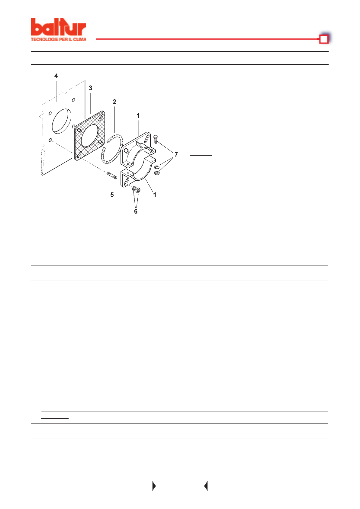
When tightening the fl ange, it is important to do it
them. Since the locking system is highly effi cient,
that the combustion head is kept in a horizontal
tank will considerably lengthen the time required to get the fuel up to pressure. Therefore the burner could easily
then it must be made according to the specifi c instructions of the boiler manufacturer).
4) Fuel pipelines should be made according to our diagram.
for nozzles with a 45° spray angle. Only in special cases can nozzles with a different spray angle be fi tted; in
these cases, however, make sure that the nozzle with a different spray angle will not cause problems (fl ame
voltage ratings suitable for the burner. Check that tha main line, the relevant switch with fuses (essential) and the
4 - Boiler plate
Page 28

the use of threaded connections which often cause air infi ltrations and disturb pump operations and consequently
those of the burner. Where a removable fi tting is required, use the welded fl ange method with a fuel resistant
towards the burner to avoid possible formation of gas bubbles. Where more than one burner is installed in one
When the viscosity of the fuel oil to be used exceeds the pumping limit, (see diagram) it is necessary to heat the
fact; the electrical resistances installed in the burner only higher the oil temperature when the thermal stage
the cistern of fuel oil (5° E at 50° C) should not exceed 30° C.
AUXILIARY PUMP
Page 29
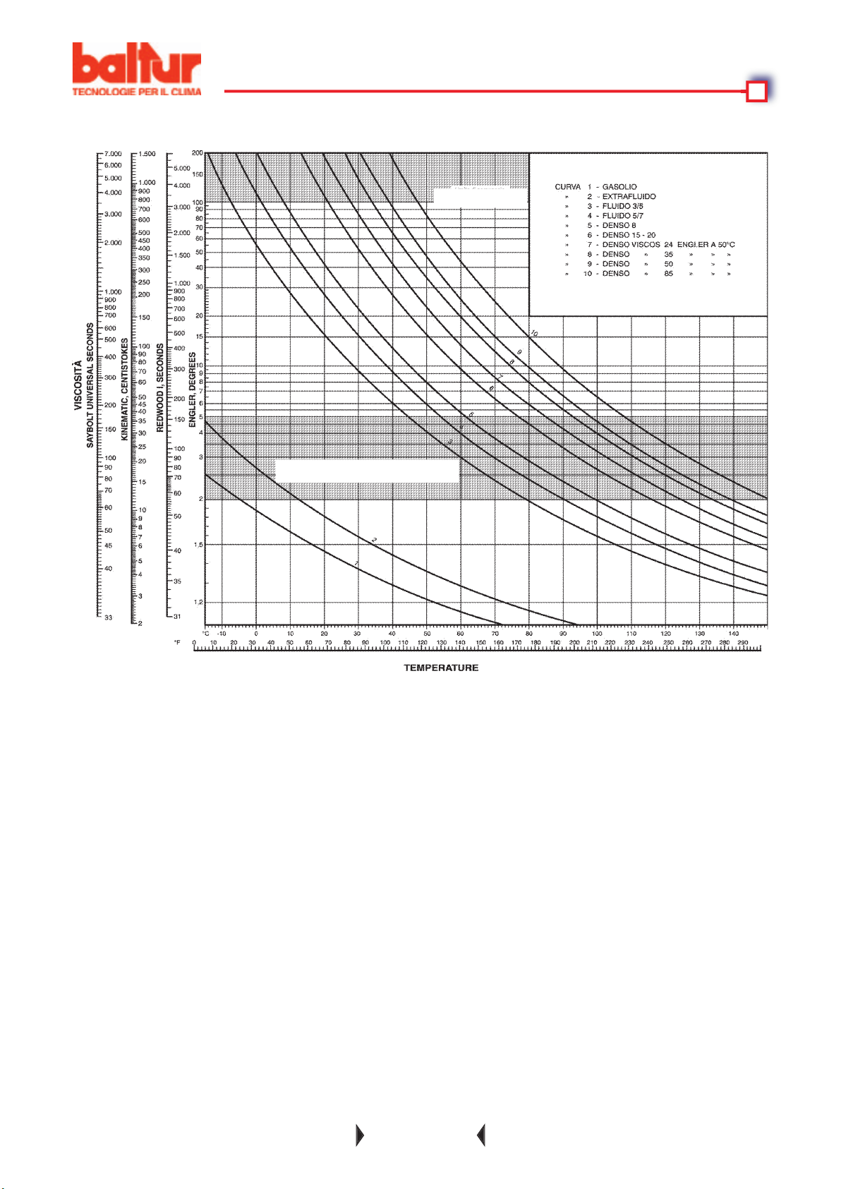
VISCOSITY - TEMPERATURE DIAGRAM
viscosity fi eld for ionisation
Page 30
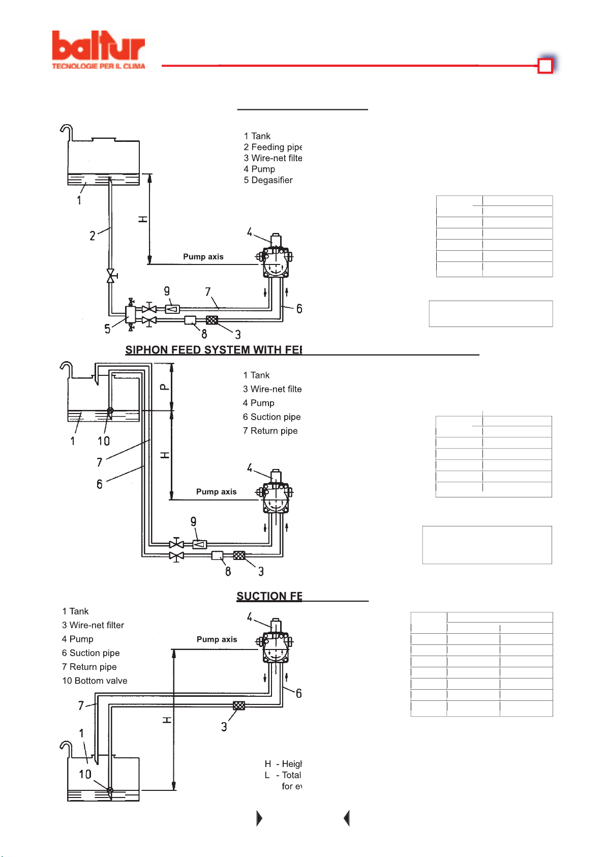
WITH FUEL OIL FROM 5°E AT 50 °C
meters Ø = 1" Ø 1" 1/4
0,5 22 35
1 17 35
1,5 12 35
2 7 21
2,5 3 8
3 - -
3,5 - -
meters Ø = 1" Ø 1" 1/4
0,5 22 35
1 17 35
1,5 12 35
2 7 21
2,5 3 8
3 - -
3,5 - -
for every elbow or gate valve.
meters meters
Ø = 1"
1 31
2 35
2,5 35
3 35
meters meters
Ø = 1"
1 31
2 35
2,5 35
3 35
meters meters
Ø = 1"
1 31
2 35
2,5 35
3 35
meters meters
Ø = 1"
1 31
2 35
2,5 35
3 35
4 Pump
4 Pump
4 Pump
Page 31
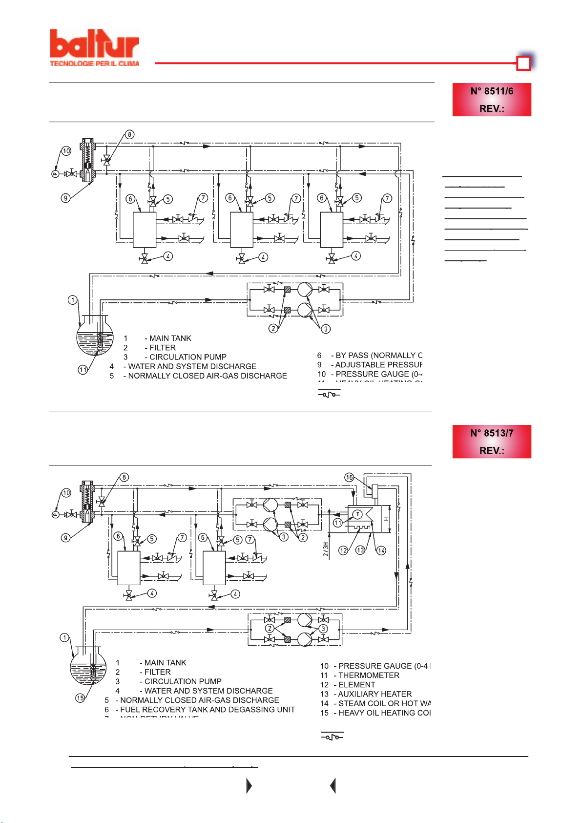
2 - FILTER
3 - CIRCULATION PUMP
4 - WATER AND SYSTEM DISCHARGE
HEATING ELECTRICAL LEAD (IF NECESSARY)
the burner and about 0.5 m, above the pump.
the burner and about 0.5 m, above the pump.
2 - FILTER
3 - CIRCULATION PUMP
4 - WATER AND SYSTEM DISCHARGE
very of hot oil
very of hot oil
to the burner and
the pump.
the pump.
HEATING ELECTRICAL LEAD (IF NECESSARY)
Page 32

Voltage will reach the thermostat that commends the resistances by passing through the boiler thermostat(s);
therefore these thermostats must be closed. Control of the resistances through the boiler thermostat is to avoid the
fuel oil boiling during the control box's pauses in operations, and to avoid an unnecessary waste of electricity.
When the resistances have been connected in this way, they will heat the fuel oil in the pre-heater tank.
When the oil has been heated suffi ciently, the minimum thermostat closes.
When the minimum thermostat has been closed, if the other (regulation and safety) thermostats allow it, voltage
will reach the control box which will start functioning and connect the burner component devices according to its
taneously; the pump which circulates hot oil in the pipe system, expels cold oil and any gas bubbles through the
When the electrovalve closes, an increase in pressure in the delivery pipes follows. Ehen the pressure reaches
to 20 bar because there is a pressure drop (
∆
As soon as atomized oil comes out of the nozzle, it is ignited by the spark between electrodes which has been
transformer is then disconnected. From the moment that the fl ame appears in the combustion chamber, the burner
When the boiler temperature or pressure reaches the limit set on the thermostat or pressure switch, the burner
will stop. Subsequently, when the temperature or pressure drops below the re-closing limit set on the thermostat
which will open and rapidly discharge the pressure existing in the tank; the atomized oil spray will be intercepted
tically to shut down. If the programme is interrupted (voltage failure, manuel or thermostat intervention) during
the start-up cycle and subsequently re-connected (return of voltage, manual or thermostat intervention etc.) the
While the burner is operating, the resistances are connected and disconnected according to the requirements by
the relative thermostat, and this is indicated by a yellow light fi tted on the burner.
Page 33
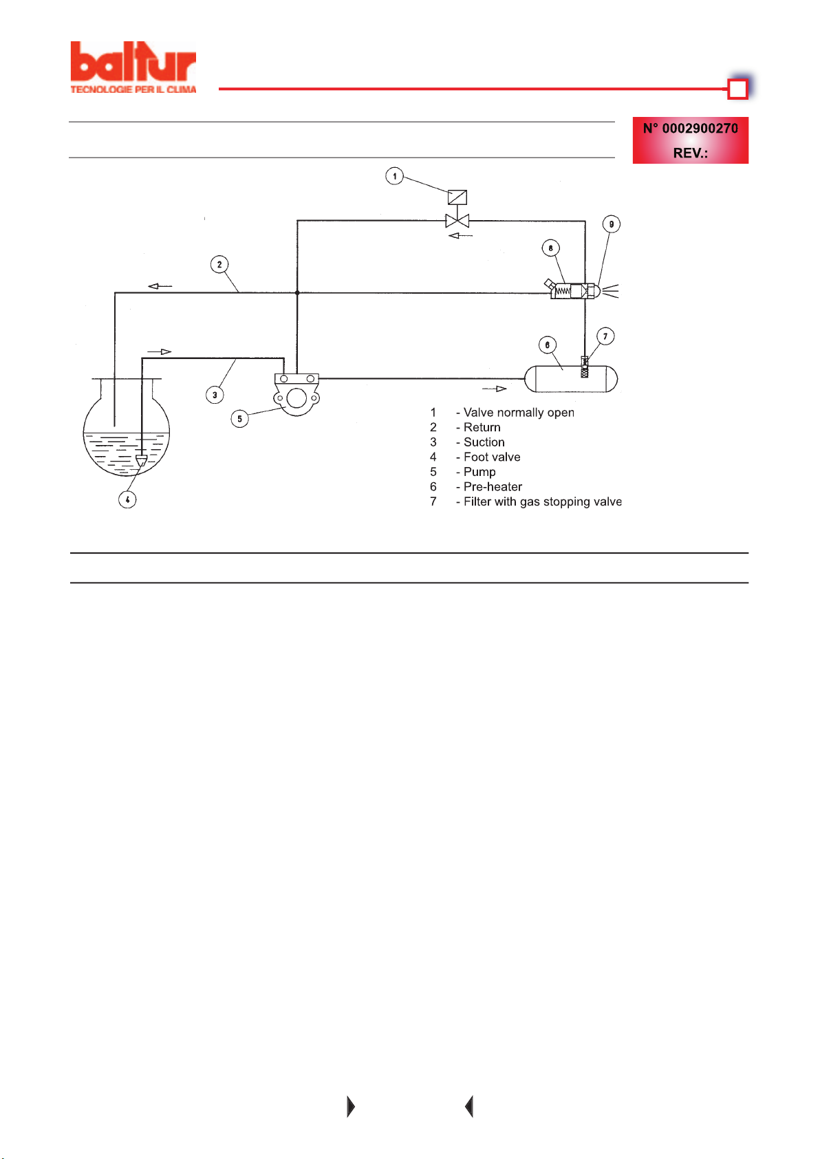
4 - Foot valve
∆
the mobile part) for a few seconds and watch the sense of rotation of the fan. If ir is necessary to change the
Wait until the fan is moving very slowly before truing to ascertain the sense of direction; it is possible to
4) Dip the end of the fl exible suction pipe in a tin containing either lubrifi cation oil or fuel oil (do not use low
viscosity products such as light oil, crude oil, petrol, kerosene, etc.).
Wait until the pump has sucked in an amount of lubrifi cant equal to 1 or 2 glassfuls, then stop.
Note:
When fuel is seen coming out of the riturn pipe (not yet connected), stop.
Note:
Page 34

the electrical diagram of the control box.
4) When the burner is operating, proceed with regulating the air (as described in point 1), in order to obtain
thequantity of air considered necessary for good combustion. A control of combustion should be made with
the appropriate instruments; the percentage of Carbon Dioxide (CO
2
We adwise regulating in such a way as to obtain a soft fl ame, bright orange in colour. It should be remembered
that, in order to regulate properly, the water in the system should be at the right temperature and the burner
tion of gas in the pre-heater, etc.. If necessary, higher or lower these values keeping in mind that the regulation
thermostat should be at a temperature of about 15° C higher than that at which the minimum thermostat is
the nozzle with a viscosity rate
exceeding 2° E. This is indispensable in order to obtain good atomization.
After starting up the burner, check the safety devices (photoresistant cell, shut down system, thermostats).
Page 35

which causes the burner to stop. The thermostat should trip within a maximum tolerance of 5 to 10° C in
AIR REGULATION ON THE COMBUSTION HEAD
they allow the burner to operate with a lower grade of smoke and good fl ame stability.
has been
with the air regulation
with the air regulation
When reducing the air passage on the combustion head, avoid closing it completely.
When reducing the air passage on the combustion head, avoid closing it completely.
to the disk is not obtained, bad combustion and excessive heating of the head could occur which would result in its
to the disk is not obtained, bad combustion and excessive heating of the head could occur which would result in its
A control can be carried out by looking through the spy hole situated at the back of the burner;
then tighten home the screws that lock the position of the air regulation device on the combustion head.
the air velocity in exit is so high as to render ignition diffi cult. If this does happen, move it backwards, gradually,
Page 36

the end of the hrating season:
It may be necessary to do this more often.
Page 37

The appliance goes into block with
fl ame on (red light on).
toring device.
The appliance goes into block, spraying
fuel, without igniting any fl ame (red
The breakdown is limited to the ignition
water or other), is properly preheated
The appliance goes into block, spraying
fuel, wothout igniting any fl ame (red
The appliance goes into clock without
4) Dirty disk or orifi ce
earthed
4) Ignition transformer shorted
they are dirty or have broken insulation; also
4) Excess combustion - supporting air
closed down
4) No fuel oil in the fuel tank
heater, causing it to fi ll up slowly. (in this
case the pressure gauge will only slowly
reach the preset operating pressure value;
too late with respect to the maximum time
permitted by the programmer)
4) Clean
4) Replace
fi lter trough the plugs provided. If necessary
drain from the fuel tank using a suitable pump
(never use the burner pump to do this)
4) Reduce combustion - supporting air
4) Fill fuel tank
turns and discharge any water. If fuel comes
the evaporation of fuel; Therefore regulate
the temperature on the control thermostat,
the inclination of the tank as described in
the chapter "Application of the burner to
the boiler"
Page 38

4) Dirty fi lter
4) Total heating coil power lower than
failure
4) Dirty or worn nozzle
fl uid oil
4) Dismantle and clean
4) Decrease fl ow rate, insofar as is possible
with the plant's heating requirements
ter control thermostat
4) Clean or replace
fuel tank as well, using a suitable pump
Page 39

4) Nozzle capacity too low with respect to
for the
type of fuel oil employed
4) Water in the fuel oil
too closed down
(lower than the dew point)
(below 180 °C)
(below 180°C)
4) Replace the nozzle, increasing its ca-
4) Drain water from the preheating tank and
the mesh fi lter trough the drain plugs.
tank as well, using a suitable pump (ne-
ver use the burner pump to do this)
te any openings where cold air can enter
Page 40
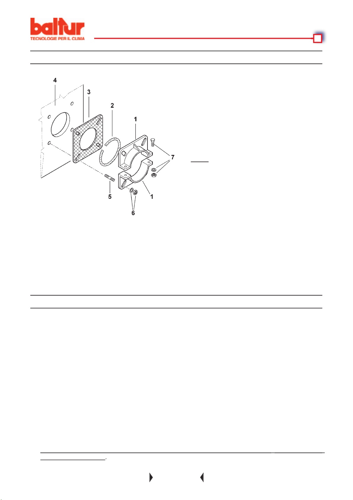
Antes de proceder a la instalación hay que asegurarse de que:
4) Las tuberías del combustible tienen que montarse como en nuestros esquemas.
toberas con ángulo de pulverización de 45°. Solamente en casos excepcionales se podrán montar toberas
4 - Placa de la caldera
Page 41

Asegurarse de que la línea eléctrica a la que se quiere conectar el aparato esté alimentada con valores de tensión
y frecuencia aptos al quemador.
Asegurarse de que la línea principal, el relativo interruptor con fusibles (indispensable) y el eventual limitador
funcionamiento de la bomba y del quemador. Donde sea indispensable utilizar un enlace desmontable, se emplee
función de la posición de la cisterna respecto al quemador. El tubo de aspiración tiene que estar colocado hacia
funcionalmente perjudiciales.
te un gran ahorro de energía eléctrica, de hecho las resistencias eléctrica, de hecho las resistencias eléctricas
Page 42
40 / 59
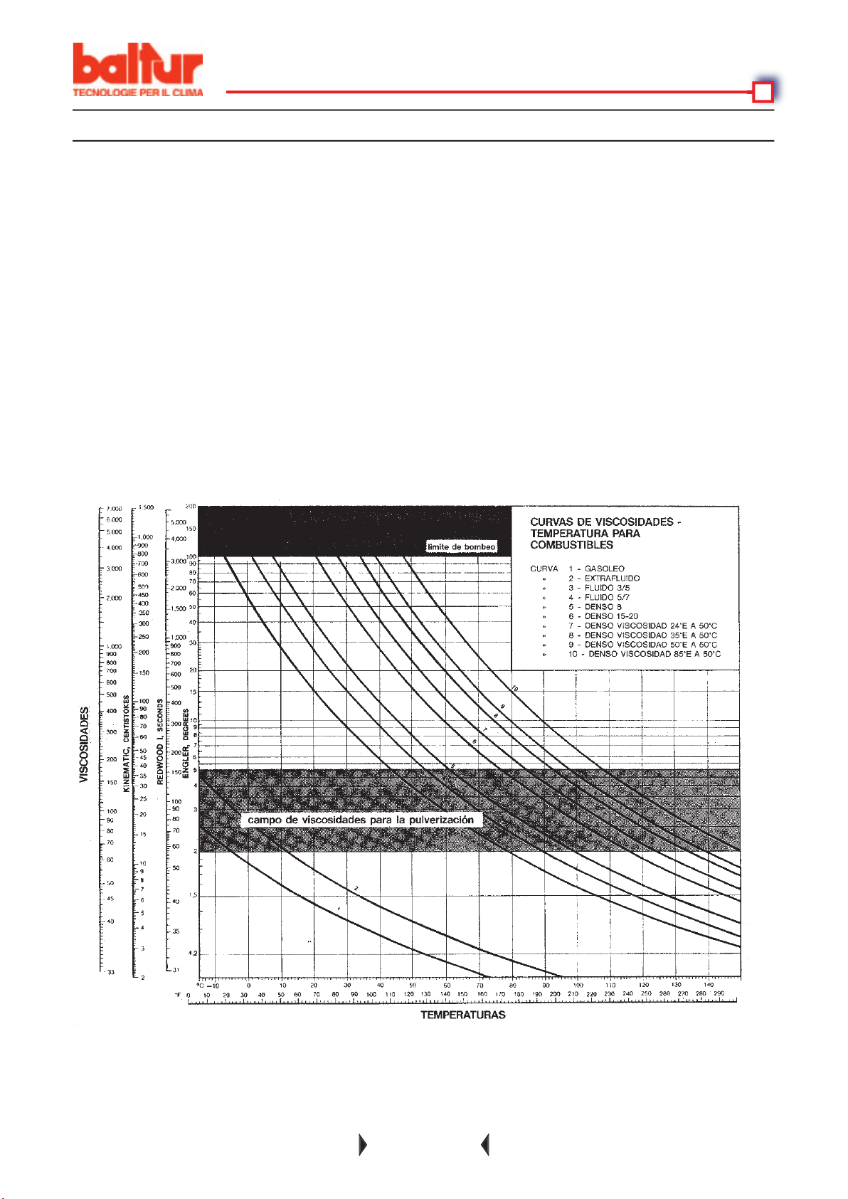
(Ver BT 8511/6 - BT 8513/7)
telerruptor del motor).
Page 43
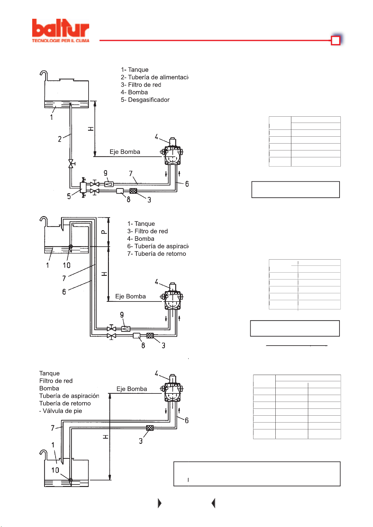
41 / 59
metros Ø = 1" Ø 1" 1/4
0,5 22 35
1 17 35
1,5 12 35
2,5 3 8
3 - -
3,5 - -
metros Ø = 1" Ø 1" 1/4
0,5 22 35
1 17 35
1,5 12 35
2,5 3 8
3 - -
3,5 - -
metros
Ø = 1"
1 31
2 35
2,5 35
3 35
metros
Ø = 1"
1 31
2 35
2,5 35
3 35
metros
Ø = 1"
1 31
2 35
2,5 35
3 35
metros
Ø = 1"
1 31
2 35
2,5 35
3 35
y retorno = 1 bar
y retorno = 1 bar
Cuando falten otros accesorios en las tube-
4- Bomba
4- Bomba
4- Bomba
Page 44
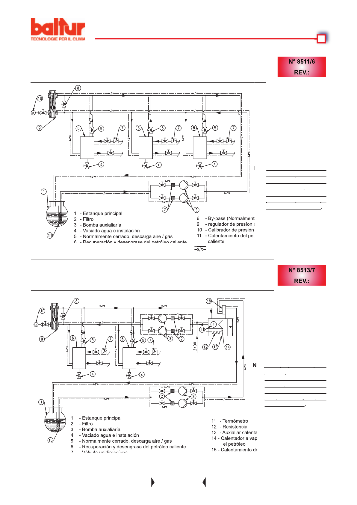
42 / 59
400 mm) deberia instalar-
400 mm) deberia instalar-
4 - Vaciado agua e instalación
4 - Vaciado agua e instalación
Cable eléctrico de calentamiento (si alguno)
caliente
Cable eléctrico de calentamiento (si alguno)
Cable eléctrico de calentamiento (si alguno)
Cable eléctrico de calentamiento (si alguno)
Cable eléctrico de calentamiento (si alguno)
Page 45

43 / 59
y prelavado
tato lo consiente). La tensión llega al termostato que acciona las resistencias atravesando el termostato o los
termostatos de la caldera; es necesario que también estos termostato estén cerrados.
Alcanzando el valor al que está tarado el dispositivo de regulación de la caldera (termostato o presostato) este
y, si la llama se vuelve a encender normalmente, el funcionamiento del quemador comienza nuevamente; en el
Page 46
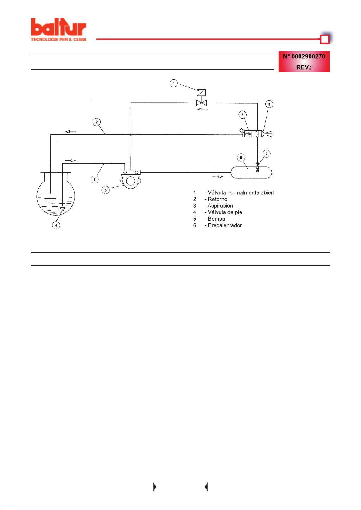
44 / 59
4 - Válvula de pie
vacío, se podrían quemar.
través de la luz indicadora situada en la parte posterior de la caja de espiral. Para poner en funcionamiento
Atención:
Esperar, para ver con seguridad el sentido de rotación, a que el impulsor gire muy despacio
ya que es posible interpretar equivocadamente el sentido de rotación.
4) Sumergir el extremo del latiguillo fl exible de aspiración en un recipiente con fuel lubrifi cante o fuel-oleo
Las bombas que trabajan a 2800 revoluciones ne deben trabajar en seco, porque se podrían
bloquear (agarrotamiento) en poco tiempo.
Page 47

45 / 59
tando, de la bomba, el tapón conectado al manómetro, de manera que descargue más libremente el
Antes de encender hay que asegurarse de que:
y de la campana de la chimenea).
y caldera) están cerrados, la conexión del dispositivo que realiza su programa conectando los dispositivos
funcionamiento”.
4) Cuando el quemador está funcionando, se pasa a regular el aire, (interviniendo como se ha descrito en el
2
Aconsejamos regularlo de manera que se obtenga una llama suave, de color naranja claro.
to, al momento del control de aprobación, hay que comprobar que estos valores no comporten anomalías
superior a 2 °E. Esta condición es indispensable para tener una buena
Page 48

46 / 59
tencia no ve la luz y en el tiempo determinado por el programador se bloquea. Se tiene que desbloquear
(Ver BT 8608/1)
calentamiento de la cabeza con un consiguiente deterioramento rápido.
calentamiento de la cabeza con un consiguiente deterioramento rápido.
Page 49

47 / 59
y control como está descrito en el capítulo “Descripción del funcionamiento”.
también por irregularidades temporáneas (un poco de agua en el combustible, aire en las tuberiás, etc.), en estos
La tobera o toberas tienen que sustituirse almenos cada dos estaciones de calentamiento.
Page 50

48 / 59
tible esté en buenas condiciones (no
4) Disco o boca sucios
4) Transformador de encendido cortado
4) Paso de aire entre disco y boca
4) Falta gasóleo en el tanque
contrario al que indica la fl echa
truido
4) Limpiar
4) Substituirlos
fi ltro desbastador mediante los tapones
4) Corregir la posición del dispositivo de la
4) Efectuar llenado
también que el depósito esté inclinado
Page 51

49 / 59
4) Filtro desbastador sucio
tubería de aspiración
4) Potencia total de las resistencias inferior a
tensión en línea
4) Boquilla inefi caz a causa de suciedad o
avería
4) Boquilla con caudal insufi ciente
no adecuado
4) Desmontar y lavar
tubería para reducir la distancia
toda la tubería
4) Disminuir el caudal con relación a la
vuelva la tensión
termostato regulador del precalentador
4) Limpiar o substituir
también del tanque mediante una bomba
4) Aumentar el caudal de la boquilla
Page 52

ventilador de aspiración en la chimenea)
4) Presencia de agua en el petróleo pesado
falta de aislamiento o infiltraciones de
4) Eliminar del depósito precalentador y
frío
Page 53
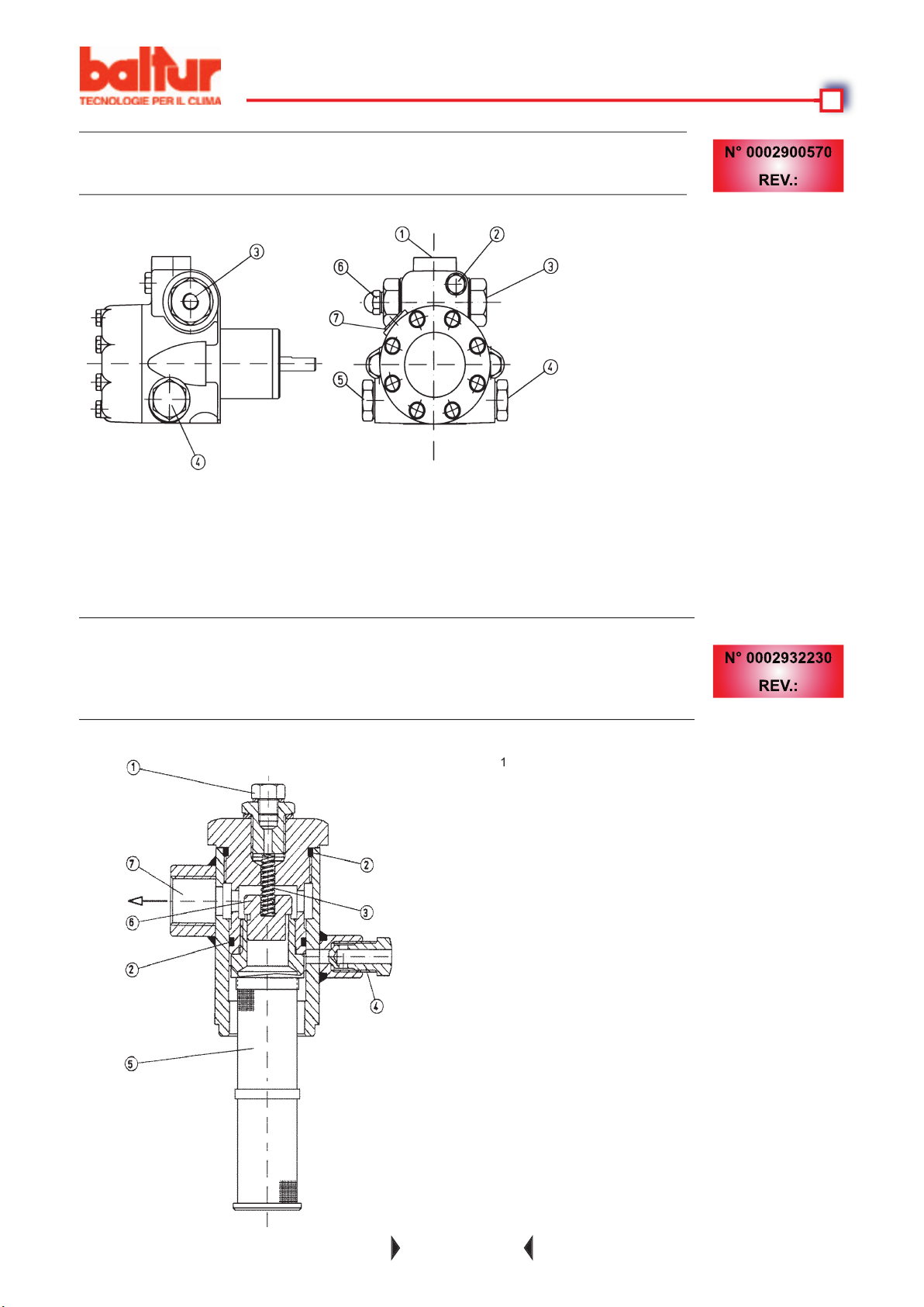
SFOGO ARIA (R 1/8")
4 - ATTACCO VUOTOMETRO (R 1/2")
PRESSIONE POMPA
4) Tappo sfi ato aria
4) Breather pipe plug
4) Tapón purga aire
4 - VACUUM GAGE CONNECTION (R 1/2")
4 - CONEXIÓN VACUOMETRO (R 1/2")
Page 54
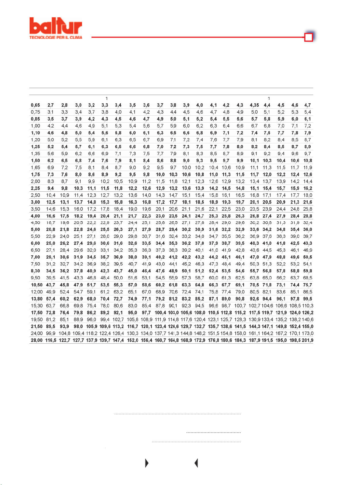
........................................................................................
......................................
..............................................................
Minimum calorifi c value
≅
100 Pa
2
Page 55
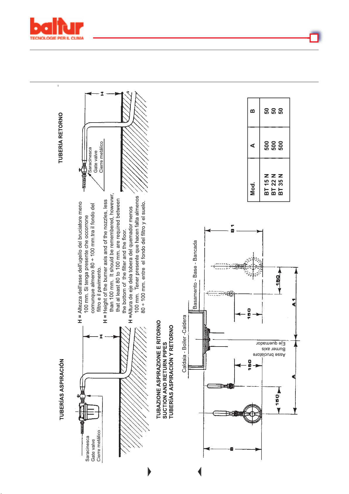
VAL OF THE PIPELINES IN THE BOILER ROOM DETALLES DE LA LLEGADA DE LAS
Asse bruciatore
Burner axis
Eje quemador
Altezza dell'asse dell'ugello del bruciatore meno
fi ltro e il pavimento.
Height of the burner axis and of the nozzles, less
than 100 mm. It should be remembered, howevwr,
that al least 80 to 100 mm. are required between
Altura de eje dela tobera del quemador menos
Page 56
Page 57
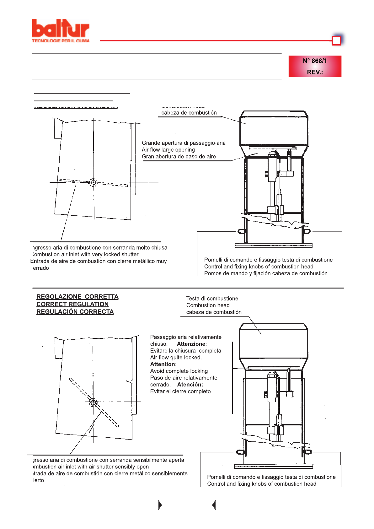
Air fl ow large opening
Attenzione:
Air fl ow quite locked.
Attention:
Avoid complete locking
Atención:
Page 58
Page 59
Page 60
Page 61
Page 62
BALTUR S.p.A.
Via Ferrarese 10 - 44042 CENTO (Ferrara) ITALIA
Tel. 051.684.37.11 Fax 051.685.75.27/28
(International Tel. ++39.051.684.37.11 - Fax ++39.051.683.06.86)
http://www.baltur.it - http://www.baltur.com
E-MAIL [email protected]
Per informazioni sui nostri Centri Assistenza
Telefonare a:
 Loading...