

baltur BGN 200 LX, BGN 390 LX, BGN 390 LX-V, BGN 200 LX-V, BGN 540 LX Maintenance, Use And Installation Manual
...
EN
SP
FR
0006081062_200904
Manuale
istallazione,
impiego,
manutenzione.
BGN 200 LX / LX-V
BGN 300 LX / LX-V
BGN 390 LX / LX-V
BGN 540 LX / LX-V
Maintenance,
use and
installation
manual
Manual de
mantenimiento,
uso e
instalación
Manuel
d’installation,
utilisation et
entretien


0006081062_200904
- Before using the burner for the first time please carefully read the chapter “WARNINGS NOTES FOR THE USER : HOW
TO USE THE BURNER SAFELY” in this instruction manual, which is an integral and essential part of the product. The
works on the burner and on the esystem have to be carried out only by competent people.
- Read carefully the instructions before starting the burner and service it.
- The system electric feeding must be disconnected before starting working on it.
- If the works are not carried out correctly it is possible to cause dangerous accidents.
- Antes de empezar a usar el quemador lea detenidamente el folleto “ADVERTENCIAS DIRIGIDAS AL USUARIO PARA
USAR CON SEGURIDAD EL QUEMADOR” que va con el manual de instrucciones y que constituye una parte integrante
y esencial del producto.
- Lea atentamente las instrucciones antes de poner en funcionamento los quemadores y efectuar las tareas de mantenimiento.
- Los trabajos que se efectúen al quemador y a la instalación deben ser efectuados sólamente por personal cualificado.
- La alimentación eléctrica de la instalación se debe desconectar antes de iniciar los trabajos.
- Si los trabajos no son efectuados correctamente se corre el riesgo de que se produzcan accidentes peligrosos.
- Avant de commencer à utilise le brûleur,lire attentivement les recommandations de la notice “RECOMMANDATIONS A
L’ATTENTION DE L’UTILISATEUR POUR UN USAGE DU BRULEUR EN TOUTE SECURITE” jointe au manuel d’instructions et qui constitue une partie intégrante et essentielle du produit.
- Lire attentivement les instructions avant de mettre en fonction le bruleur et pour son entretien correct.
- Les travaux sur le bruleur et sur l’installation doivent etre executes seulement par du personnel qualifie.
- L’alimentation electrique de l’installation doit etre debranche avant de commencer les travaux.
- Si les travaux ne sont pas executes correctement il y a la possibilite de causer de dangereux incidents.
E
N
G
L
I
S
H
F
R
A
Ç
A
I
S
E
S
P
A
Ñ
O
L
S
S
S
- Prima di iniziare a usare il bruciatore leggere attentamente quanto esposto nell’opuscolo “AVVERTENZE PER L’UTENTE, PER
L’USO IN SICUREZZA DEL BRUCIATORE” presente a corredo del manuale istruzioni, che costituisce parte integrante ed essenziale
del prodotto.
- Leggere attentamente le istruzioni prima di mettere in funzione il bruciatore o di eseguire la manutenzione.
- I lavori sul bruciatore e sull’impianto devono essere eseguiti solo da personale qualificato.
- L’alimentazione elettrica dell’impianto deve essere disinserita prima di iniziare i lavori.
- Se i lavori non sono eseguiti correttamente si rischiano incidenti pericolosi.
I
T
A
L
I
A
N
O

0006081062_200904
33 / 36
0006081062_200904
I
T
A
L
I
A
N
O
DUNGS mod. MB-VEF BO1 / DMV-VEF
Taratura del gruppo regolazione-pressione
!
Il gruppo regolazione- pressione viene pre-tarato in
fabbrica. I valori di taratura devono essere poi adattati
sul posto alle esigenze dell‘ impianto.
La valvola modulante mod. MB-VEF B01 opera aumentando
automaticamente l’erogazione del gas se aumenta l’erogazione
dell’aria, e riduce automaticamente l’erogazione del gas se viene
ridotta l’erogazione dell’aria. Pertanto l’erogazione della quantità di
gas al “minimo“ ed al “massimo” del bruciatore deve essere regolata esclusivamente regolando il “minimo” e il “massimo”, dell’aria di
combustione. In pratica si opera sulle due “cammes” che regolano
il minimo e il massimo del servomotore di regolazione dell’aria.
Tenendo presente questo principio, consigliamo di agire come esposto di seguito per regolare il bruciatore. Accedere e mantenere il
bruciatore al minimo della modulazione (valvola modulante aperta
al minimo), verificare il contenuto di CO
2
, oppure O2 e CO nei fumi
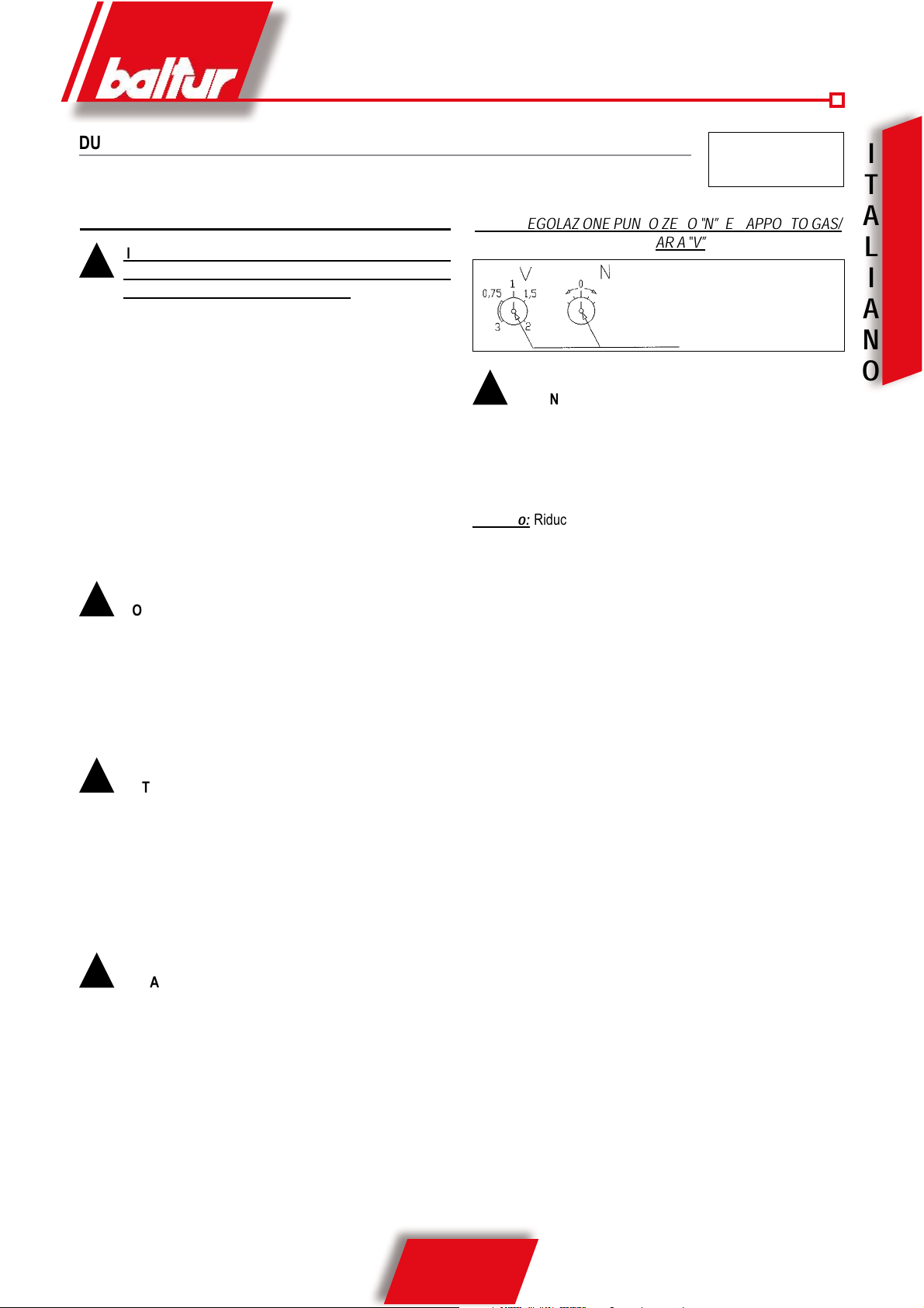
e correggere, se necessario, con la vite di regolazione per correzione punto zero ”N” il rapporto gas/aria, ottenuto con lo spostamento parallelo delle curve caratteristiche (vedi diagramma).
!
NOTA: Per diminuire la quantità di aria rispetto al gas
e quindi per aumentare la percentuale di CO2 portare la
regolazione ‘N” verso valori positivi (+). Per aumentare
la quantità di aria rispetto al gas e quindi per diminuire la
percentuale di CO2, portare la regolazione “N” verso valori
negativi (-). Portare il bruciatore al massimo della modulazione misurare il contenuto di CO2 oppure O2e CO nei fumi
e correggere, se necessario, il rapporto tarato agendo sulla
vite “V” fino a quando il valore misurato è ottimale.
!
NOTA: Per diminuire la quantità di aria rispetto al gas e
quindi per aumentare la percentuale di CO2 portare la regolazione “V” verso rapporti più grandi. Per aumentare la
quantità di aria rispetto al gas e quindi per diminuire la percentuale di CO2 portare la regolazione “V” verso rapporti
più piccoli (vedi diagramma). Una volta regolato il massimo
della modulazione, ritornare nella posizione di minimo e
verificare le regolazioni precedentemente effettuate. Se
necessario correggere nuovamente il punto “0” con la regolazione “N”
!
NOTA: Quando per ottenere ai bassi carichi (modulazione
al minimo) valori di CO2 oppure O2 buoni, è stato necessario eseguìre una modifica parallela della caratteristica,
occorre verificare nuovamente la regolazione del rapporto
gas-aria e, se necessario, variare il rapporto gas/aria con
la vite “V”.
Sede per chiave esagonale cava da 2,5 mm.
N° 0002910621 /
0006080717
Rev. 22/10/2004
!
ATTENZIONE: Da quanto sopra esposto risulta evidente
che la variazione di pressione dell’aria, che si ottiene nel
bruciatore, agendo sul dispositivo di regolazione dell’aria alla
testa di combustione (variazione della sezione di passaggio
dell’aria) determina automaticamente ed inevitabilmente una
variazione di erogazione di gas.
Esempio:
Riducendo la sezione di passaggio dell’aria tra testa e
disco si ottiene un aumento della pressione aria nel bruciatore e
una riduzione, dell’erogazione di aria nel focolare, di conseguenza
la valvola gas MB-VEF B01 rileva l’aumento di pressione e aumenta
l’erogazione del gas, diventa quindi indispensabile la correzione
(riduzione) dell’erogazione di gas agendo sui relativi dispositivi di
cui la valvola è provvista.
VITI DI REGOLAZIONE PUNTO ZERO “N” E RAPPORTO GAS/
ARIA “V”
34 / 36
0006081062_200904
I
T
A
L
I
A
N
O
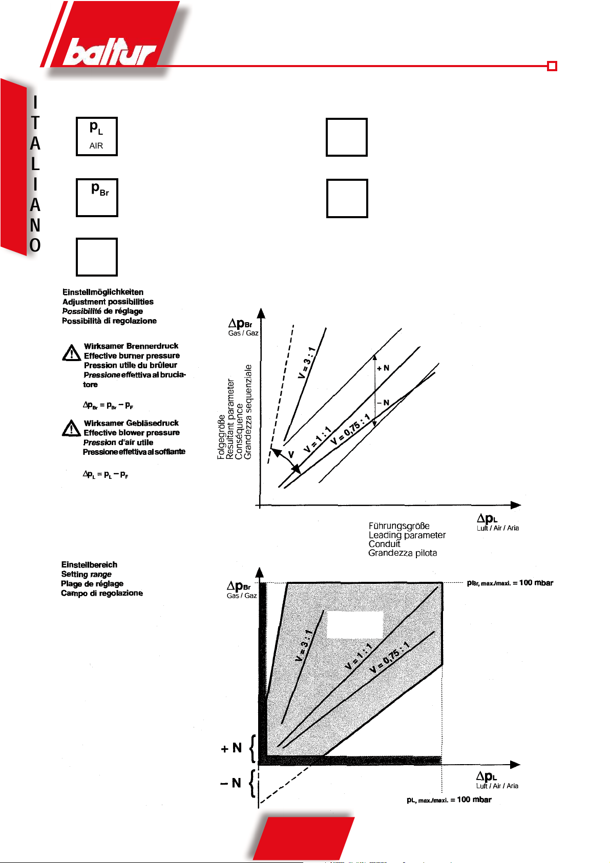
p
L
AIR
p
Br
GAS
p
F
Combustion
atmosfere
V
min./mini
max/maxi
N
± 1 mbar
p
L
max/maxi = 100 mbar
V
max/maxi = 3:1
p
F
max/maxi = +5 mbar
pBrmax/maxi = 100 mbar
p
L
min./mini = 0,4 mbar
pBrmin./mini = 0,5 mbar
pFmin./mini = -2 mbar
V
min./mini = 0,75:1
V
= pBr: p
L
Correzione punto zero ± 1 mbar
MB-VEF
Campo di regolazione
35 / 36
0006081062_200904
I
T
A
L
I
A
N
O
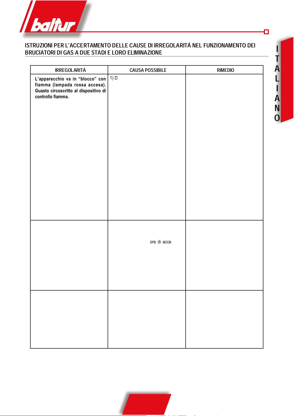
ISTRUZIONI PER L’ACCERTAMENTO DELLE CAUSE DI IRREGOLARITÁ NEL FUNZIONAMENTO DEI
BRUCIATORI DI GAS A DUE STADI E LORO ELIMINAZIONE
IRREGOLARITÁ CAUSA POSSIBILE RIMEDIO
L’apparecchio va in “blocco” con
fiamma (lampada rossa accesa).
Guasto circoscritto al dispositivo di
controllo fiamma.
1) Disturbo della corrente di Ionizzazione
da parte del trasformatore di accensione.
2) Sensore di fiamma (sonda ioniz-zazione
o cellula UV) inefficiente
3) Sensore di fiamma (sonda ioniz-zazione
o cellula UV) in posizione non corretta.
4) Sonda ionizzazione o relativo cavo a
massa
5) Collegamento elettrico interrotto del
sensore di fiamma
6) Tiraggio inefficiente o percorso fumi
ostruito.
7) Disco fiamma o testa di combustione
sporchi o logori.
8) Cellula UV sporca o unta.
9) Apparecchiatura guasta.
10) Manca ionizzazione.
1) Invertire l’alimentazione (lato 230V)
del trasformatore di accensione e
verificare con micro-amperometro
analogico
2) Sostituire il sensore di fiamma
3) Correggere la posizione del sensore di
fiamma e, successivamente, verificarne
l’efficienza inserendo il micro-amperometro analogico.
4) Ve r if i ca r e vi s i va m en t e e co n
strumento.
5) Ripristinare il collegamento.
6) Controllare che i passaggi fumo caldaia/
raccordo camino siano liberi.
7) Verificare visivamente ed eventualmente sostituire.
8) Pulire adeguatamente.
9) Sostituirla.
10) Se la “massa” dell’apparecchiatura non
è efficiente non si verifica la corrente
di ionizzazione. Verificare l’efficienza
della “massa” all’apposito morsetto della
apparecchiatura e al collegamento a
“terra” dell’impianto elettrico.
L’apparecchio va in “blocco”, il
gas esce, ma la fiamma non è present e ( l a mpada rossa ac c e s a ).
Guasto circoscritto al circuito di
accensione.
1) Guasto nel circuito di accensione.
2) Cavetto trasformatore d’accensione
scarica a massa.
3) Cavetto trasformatore di accensione
scollegato.
4) Trasformatore d’accensione guasto
5) La distanza tra elettrodo e massa non
è corretta.
6) Isolatore sporco e quindi l’elettrodo
scarica a massa.
1) Verificare l’alimentazione del trasfor-
matore d’accensione (lato 230V) e
circuito alta tensione (elettrodo a massa
o isolatore rotto sotto il morsetto di
bloccaggio).
2) Sostituirlo.
3) Collegarlo.
4) Sostituirlo.
5) Metterlo alla corretta distanza.
6) Pu l i re o sostitu i r e l’isolatore e
l’elettrodo.
L’apparecchio va in “blocco”, il gas
esce, ma la fiamma non è presente
(lampada rossa accesa.
1) Rapporto aria/gas non corretto.
2) La tubazione del gas non è stata
ade g u atamente s fogata da ll’aria
(caso di prima accensione).
3) La pressione del gas è insufficiente o
eccessiva.
4) Passaggio aria tra disco e testa
troppo chiuso.
1) Correg g ere il rappo r to ari a/gas
(probabilmente c’è troppa aria o poco
gas)
2) Sfogare ulteriormente, con le dovute
cautele, la tubazione del gas.
3) Verificare il valore della pressione gas
al momento dell’accensione (usare
manometro ad acqua, se possibile).
4) Adeguare l’apertura disco/testa.

36 / 36
0006081062_200904
I
T
A
L
I
A
N
O

1 / 36
0006081062_200
904
E
N
G
L
I
S
H
ENGLISH PAGE
- Technical specifications ...................................................................................................................................... “ 4
- Gas supply line - Fixing the burner to the boiler ................................................................................................ “ 13
- Measuring the pressure in the combustion chamber.......................................................................................... “ 14
- Electrical connections - Description of the operation - Description of the modulation operation........................ “ 15
- Ignition and gas regulation (methane) ................................................................................................................ “ 17
- Air regulation on the combustion head - Maintenance ..................................................................................... “ 19
- Air regulation servomotor ..................................................................................................................................“ 22
- LFL... Control box ............................................................................................................................................... “ 24
- MB-VEF B01 Monobloc valve ........................................................................................................................... “ 28
- Irregularity - cause - remedy............................................................................................................................... “ 35
- Electric diagrams ................................................................................................................................................ “ 149
!
Note
i
Information
I
Warning
Statement of Conformity
We hereby declare under our own responsibility, that our “CE” marked products Series:
Sparkgas…; BTG…; BGN…; Minicomist…; Comist…; RiNOx…, BT…; BTL…;
GI…; GI…Mist; PYR…; TS…, TBG...,
Description:
domestic and industrial blown air burners fired by gas, oil and dual fuel respect the
minimal regulation of the European Directives:
• 90/396/EEC (G.A.D)
• 92/42/EEC (B.E.D)
• 89/336/EEC (E.M.C. Directive)
• 73/23/EEC (Low Voltage Directive)
• 98/37 EEC (Machinery Directive)
and have been designed and tested in accordance with the European Standards:
• EN 676 (gas and dual fuel, gas side)
• EN 267 (light oil and dual fuel, oil side)
• EN 60335-1, 2003
• EN 50165: 1997 + A1:2001
• EN 55014 -1 (1994) and –2 (1997)
Surveillance accordingly Gas Appliances Directive 90/396/EEC made by:
CE0085 - DVGW
The Vice President and Managing Director:
Dr. Riccardo Fava

2 / 36
0006081062_200
904
E
N
G
L
I
S
H
FOREWORD
These warning notes are aimed at ensuring the safe use of the components of heating systems for civil use and the production of hot water.
They indicate how to act to avoid the essential safety of the components
being compromised by incorrect or erroneous installation and by improper
or unreasonable use. The warning notes provided in this guide also seek
to make the consumer more aware of safety problems in general, using
necessarily technical but easily understood language. The manufacturer
is not liable contractually or extra contractually for any damage caused
by errors in installation and in use, or where there has been any failure to
follow the manufacturer’s instructions.
GENERAL WARNING NOTES
• The instruction booklet is an integral and essential part of the product
and must be given to the user. Carefully read the warnings in the booklet as they contain important information regarding safe installation,
use and maintenance. Keep the booklet to hand for consultation when
needed.
• Equipment must be installed in accordance with current regulations,
with the manufacturer’s instructions and by qualified technicians. By
the term ‘qualified technicians’ is meant persons that are competent in
the field of heating components for civil use and for the production of
hot water and, in particular, assistance centres authorised by the manu-
facturer. Incorrect installation may cause damage or injury to persons,
animals or things. The manufacturer will not in such cases be liable.
• After removing all the packaging make sure the contents are complete
and intact. If in doubt do not use the equipment and return it to the
supplier. The packaging materials (wooden crates, nails, staples, plastic
bags, expanded polystyrene, etc.) must not be left within reach of children as they may be dangerous to them. They should also be collected
and disposed on in suitably prepared places so that they do no pollute
the environment.
• Before carrying out any cleaning or maintenance, switch off the equipment at the mains supply, using the system’s switch or shut-off systems.
• If there is any fault or if the equipment is not working properly, de-activate the equipment and do not attempt to repair it or tamper with it
directly. In such case get in touch with only qualified technicians. Any
product repairs must only be carried out by BALTUR authorised assistance centres using only original spare parts. Failure to act as above
may jeopardise the safety of the equipment. To ensure the efficiency
and correct working of the equipment, it is essential to have periodic
maintenance carried out by qualified technicians following the manufacturer’s instructions.
• If the equipment is sold or transferred to another owner or if the owner
moves and leaves the equipment, make sure that the booklet always
goes with the equipment so it can be consulted by the new owner and/
or installer.
• For all equipment with optionals or kits (including electrical), only original accessories must be used.
BURNERS
• This equipment must be used only for its expressly stated use: applied
to boilers, hot air boilers, ovens or other similar equipment and not
exposed to atmospheric agents. Any other use must be regarded as
improper use and hence dangerous.
• The burner must be installed in a suitable room that has ventilation in
accordance with current regulations and in any case sufficient to ensure
correct combustion
WARNING NOTES FOR THE USER HOW TO
USE THE BURNER SAFELY
• Do not obstruct or reduce the size of the burner’ air intake grills or the
ventilation openings for the room where a burner or a boiler is installed
or dangerous mixtures of toxic and explosive gases may form.
• Before connecting the burner check that the details on the plate correspond to those of the utility supplies (electricity, gas, light oil or other
fuel).
• Do not touch hot parts of the burner. These, normally in the areas near
to the flame and any fuel pre-heating system, become hot when the
equipment is working and stay hot for some time after the burner has
stopped.
• If it is decided not to use the burner any more, the following actions must
be performed by qualified technicians:
a) Switch off the electrical supply by disconnecting the power cable from
the master switch.
b) Cut off the fuel supply using the shut-off valve and remove the control
wheels from their position.
c) Render harmless any potentially dangerous parts.
Special warning notes
• Check that the person who carried out the installation of the burner fixed
it securely to the heat generator so that the flame is generated inside
the combustion chamber of the generator itself.
• Before starting up the burner, and at least once a year, have qualified
technicians perform the following operations:
a) Set the burner fuel capacity to the power required by the heat ge-
nerator.
b) Adjust the combustion air flow to obtain combustion yield of at least
the minimum set by current regulations.
c) Carry out a check on combustion to ensure the production of no-
xious or polluting unburnt gases does not exceed limits permitted
by current regulations.
d) Check the adjustment and safety devices are working properly.
e) Check the efficiency of the combustion products exhaust duct.
f) Check at the end of the adjustments that all the adjustment devices
mechanical securing systems are properly tightened.
g) Make sure that the use and maintenance manual for the burner is
in the boiler room.
• If the burner repeatedly stops in lock-out, do not keep trying to manually
reset but call a qualified technicians to sort out the problem.
• The running and maintenance of the equipment must only be carried
out by qualified technicians, in compliance with current regulations.
I
3 / 36
0006081062_200
904
E
N
G
L
I
S
H
ELECTRICAL SUPPLY
• The equipment is electrically safe only when it is correctly connected to an
efficient ground connection carried out in accordance with current safety
regulations. It is necessary to check this essential safety requirement.
If in doubt, call for a careful electrical check by a qualified technicians,
since the manufacturer will not be liable for any damage caused by a
poor ground connection.
• Have qualified technicians check that the wiring is suitable for the
maximum power absorption of the equipment, as indicated in the technical
plate, making sure in particular that the diameter of cables is sufficient
for the equipment’s power absorption.
• Adapters, multiple plugs and extension cables may not be used for the
equipment’s power supply.
• An ominpolar switch in accordance with current safety regulations is
required for the mains supply connection.
• The electrical supply to the burner must have neutral to ground
connection. If the ionisation current has control with neutral not to ground
it is essential to make a connection between terminal 2 (neutral) and the
ground for the RC circuit.
• The use of any components that use electricity means that certain
fundamental rules have to followed, including the following:
- do not touch the equipment with parts of the body that are wet or damp
or with damp feet
- do not pull on electrical cables
- do not leave the equipment exposed to atmospheric agents (such as
rain or sun etc.) unless there is express provision for this.
- do not allow the equipment to be used by children or inexpert
persons.
• The power supply cable for the equipment not must be replaced by the
user. If the cable gets damaged, switch off the equipment, and call only
on qualified technicians for its replacement.
• If you decide not to use the equipment for a while it is advisable to switch
off the electrical power supply to all components in the system that use
electricity (pumps, burner, etc.).
GAS, LIGHT OIL, OR OTHER FUEL SUPPLIES
General warning notes
• Installation of the burner must be carried out by qualified technicians
and in compliance with current law and regulations, since incorrect
installation may cause damage to person, animals or things, for which
damage the manufacturer shall not can be held responsible.
• Before installation it is advisable to carry out careful internal cleaning
of all tubing for the fuel feed system to remove any residues that could
jeopardise the proper working of the burner.
• For first start up of the equipment have qualified technicians carry out
the following checks:
• If you decide not to use the burner for a while, close the tap or taps that
supply the fuel.
Special warning notes when using gas
• Have qualified technicians check the following:
a) that the feed line and the train comply with current law and
regulations.
b) that all the gas connections are properly sealed.
• Do not use the gas pipes to ground electrical equipment.
• Do not leave the equipment on when it is not in use and always close
the gas tap.
• If the user of is away for some time, close the main gas feed tap to the
burner.
• If you smell gas:
a) do not use any electrical switches, the telephone or any other object
that could produce a spark;
b) immediately open doors and windows to create a current of air that
will purify the room;
c) close the gas taps;
d) ask for the help of qualified technicians.
• Do not block ventilation openings in the room where there is gas
equipment or dangerous situations may arise with the build up of toxic
and explosive mixtures.
FLUES FOR HIGH EFFICIENCY BOILERS AND SIMILAR
It should be pointed out that high efficiency boilers and similar discharge
combustion products (fumes) at relatively low temperatures into the flue.
In the above situation, traditional flues (in terms of their diameter and heat
insulation) may be suitable because the significant cooling of the combustion
products in these permits temperatures to fall even below the condensation
point. In a flue that works with condensation there is soot at the point the
exhaust reaches the atmosphere when burning light oil or heavy oil or the
presence of condensate water along the flue itself when gas is being burnt
(methane, LPG, etc.). Flues connected to high efficiency boilers and similar
must therefore be of a size (section and heat insulation) for the specific use
to avoid such problems as those described above.
WARNING NOTES FOR THE USER HOW TO
USE THE BURNER SAFELY
I

4 / 36
0006081062_200
904
E
N
G
L
I
S
H
TECHNICAL DATA
BGN
200 LX
BGN
300 LX
BGN
390 LX
BGN
540 LX
THERMIC CAPACITY
MAX kW 2150 3600 3950 5900
MIN kW
250 400 400 600
MOTOR
kW 3 7,5 7,5 15
r.p.m. 2870 2870 2870 2920
ABSORBED ELECTRICAL POWER kW 3,50 8,00 8,00 15,5
FUSE A 400 V 20 25 25 50
IGNITION TRANSFORMER 8 kV - 30 mA
VOLTAGE 3 ~ 400 V - 50 Hz
FLAME DETECTOR IONISATION PROBE Photocell UV
Natural Gas
FLOW RATE MAX m³n/h 216 362 397 593
MIN m³n/h
25 40 40 60
PRESSURE MAX mbar 360
STANDARD ACCESSORIES
BURNER FIXING FLANGE 1 1 1 1
ISOLATING GASKET 1
1 1 2
STUD BOLTS N° 4 - M12 N° 4 - M20 N° 4 - M20 N° 6 - M20
EXAGONAL NUTS N° 4 - M12 N° 4 - M20 N° 4 - M20 N° 6 - M20
FLAT WASHERS N° 4 - M12 N° 4 - M20 N° 4 - M20 N° 6 - Ø20
BGN
200 LX-V
BGN
300 LX-V
BGN
390 LX-V
BGN
540 LX-V
THERMIC CAPACITY
MAX kW 2150 3600 3950 5900
MIN kW 250 400 400 600
MOTOR
kW 3 7,5 7,5 15
r.p.m. 2870 2870 2870 2920
ABSORBED ELECTRICAL POWER kW 3,50 8,00 8,00 15,5
FUSES A 400 V 10 25 25 50
IGNITION TRANSFORMER 8 kV - 30 mA
VOLTAGE 3 ~ 400 V - 50 Hz
FLAME DETECTOR IONISATION PROBE Photocell UV-
Natural Gas
FLOW RATE MAX m³n/h 216 362 397 593
MIN m³n/h 25 40 40 60
PRESSURE MAX mbar 360
STANDARD ACCESSORIES
BURNER FIXING FLANGE 1 1 1 1
ISOLATING GASKET 1
1 1 2
STUD BOLTS N° 4 - M12 N° 4 - M20 N° 4 - M20 N° 6 - M20
EXAGONAL NUTS N° 4 - M12 N° 4 - M20 N° 4 - M20 N° 6 - M20
FLAT WASHERS N° 4 - M12 N° 4 - M20 N° 4 - M20 N° 6 - Ø20
5 / 36
0006081062_200
904
E
N
G
L
I
S
H
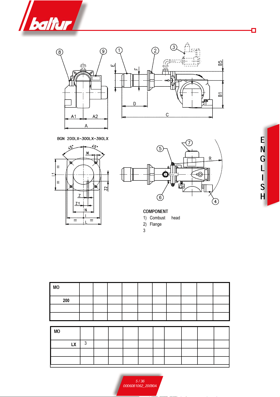
COMPONENT
1) Combustion head
2) Flange
3) Modulation valve
4) Air regulation servomotor
5) Hinge
6) Combustion head air
control knob
7) Fan motor
8) Air pressure switch
9) Control box
MOD.
A A1 A2 B1 B5 C D
MINDMAX
E
Ø
F
Ø
BGN 200 LX
835 400 435 580 150 1630 280 480 300 220
BGN 300 LX
880 400 480 580 177 1630 280 480 316 275
BGN 390 LX
880 400 480 580 177 1630 280 480 316 275
MOD.
I I1 L
MINLMAX
M N
ØRMAX
Z
Z1 Z2
BGN 200 LX
320 320 280 370 M12 260 980 12 113 54
BGN 300 LX
440 440 400 540 M20 360 980 12 150 87
BGN 390 LX
440 440 400 540 M20 360 980 12 150 87
0002471090
6 / 36
0006081062_200
904
E
N
G
L
I
S
H
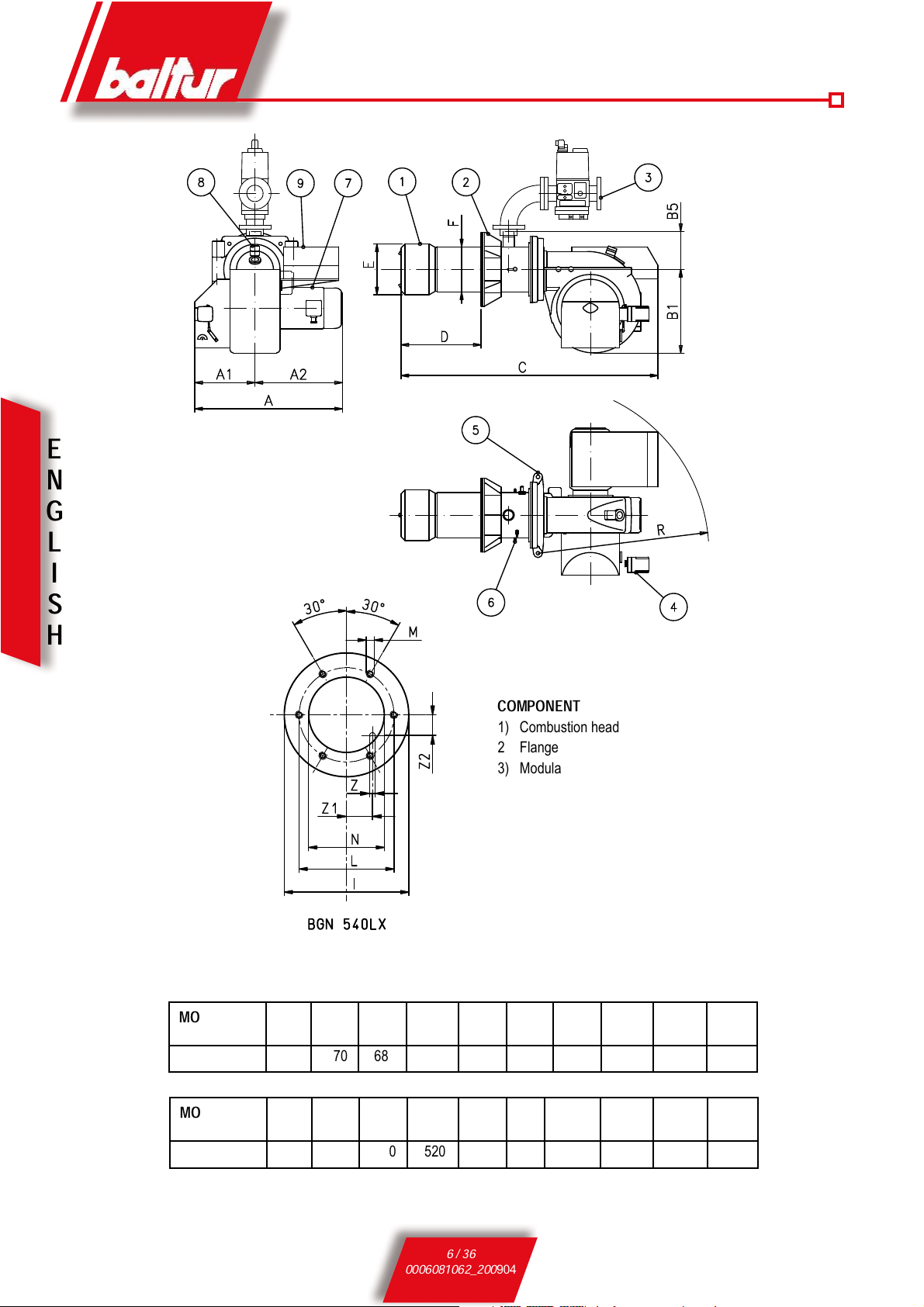
COMPONENT
1) Combustion head
2) Flange
3) Modulation valve
4) Air regulation servomotor
5) Hinge
6) Combustion head air
control knob
7) Fan motor
8) Air pressure switch
9) Control box
MOD.
A A1 A2 B1 B5 C D
MINDMAX
E
Ø
F
Ø
BGN 540 LX
1155 470 685 695 283 2110 330 600 400 355
MOD.
I I1 L
MINLMAX
M N
ØRMAX
Z
Z1 Z2
BGN 540 LX
580 - - 520 520 M20 430 1170 12 131 156
0002470911
7 / 36
0006081062_200
904
E
N
G
L
I
S
H
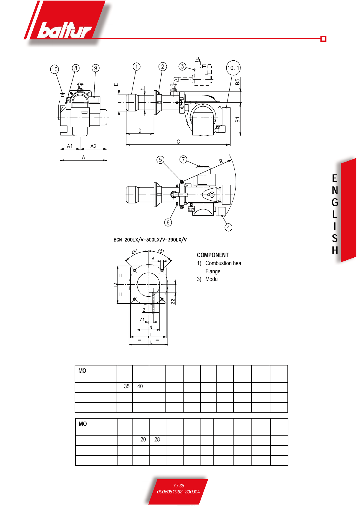
COMPONENT
1) Combustion head
2) Flange
3) Modulation valve
4) Air regulation servomotor
5) Hinge
6) Combustion head air control knob
7) Fan motor
8) Air pressure switch
9) Control box
10) Frequency converter (BGN 200 LX-V)
10.1) Frequency converter
(BGN 300 / 390 LX-V)
MOD.
A A1 A2 B1 B5 C D
MINDMAXEØ
F
Ø
BGN 200 LX-V
835 400 435 580 150 1630 280 480 300 220
BGN 300 LX-V
880 400 480 580 177 1870 280 480 316 275
BGN 390 LX-V
880 400 480 580 177 1870 280 480 316 275
MOD.
I I1 L
MINLMAX
M N
ØRMAX
Z
Z1 Z2
BGN 200 LX-V
320 320 280 370 M12 260 980 12 113 54
BGN 300 LX-V
440 440 400 540 M20 360 980 12 150 87
BGN 390 LX-V
440 440 400 540 M20 360 980 12 150 87
0002471101
8 / 36
0006081062_200
904
E
N
G
L
I
S
H
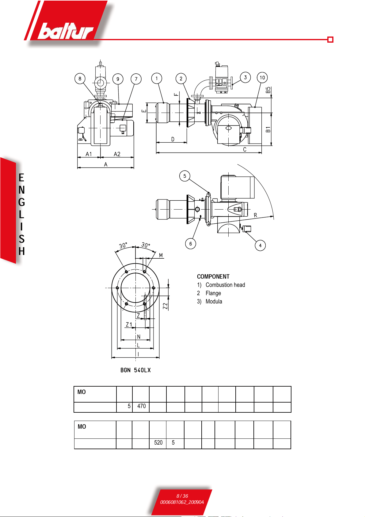
COMPONENT
1) Combustion head
2) Flange
3) Modulation valve
4) Air regulation servomotor
5) Hinge
6) Combustion head air control knob
7) Fan motor
8) Air pressure switch
9) Control box
10)Frequency converter
MOD.
A A1 A2 B1 B5 C D
MINDMAXEØ
F
Ø
BGN 540 LX-V
1155 470 685 695 283 2165 330 600 400 355
MOD.
I I1 L
MINLMAX
M N
ØRMAX
Z
Z1 Z2
BGN 540 LX-V
580 - - 520 520 M20 430 1360 12 131 156
0002471111
9 / 36
0006081062_200
904
E
N
G
L
I
S
H
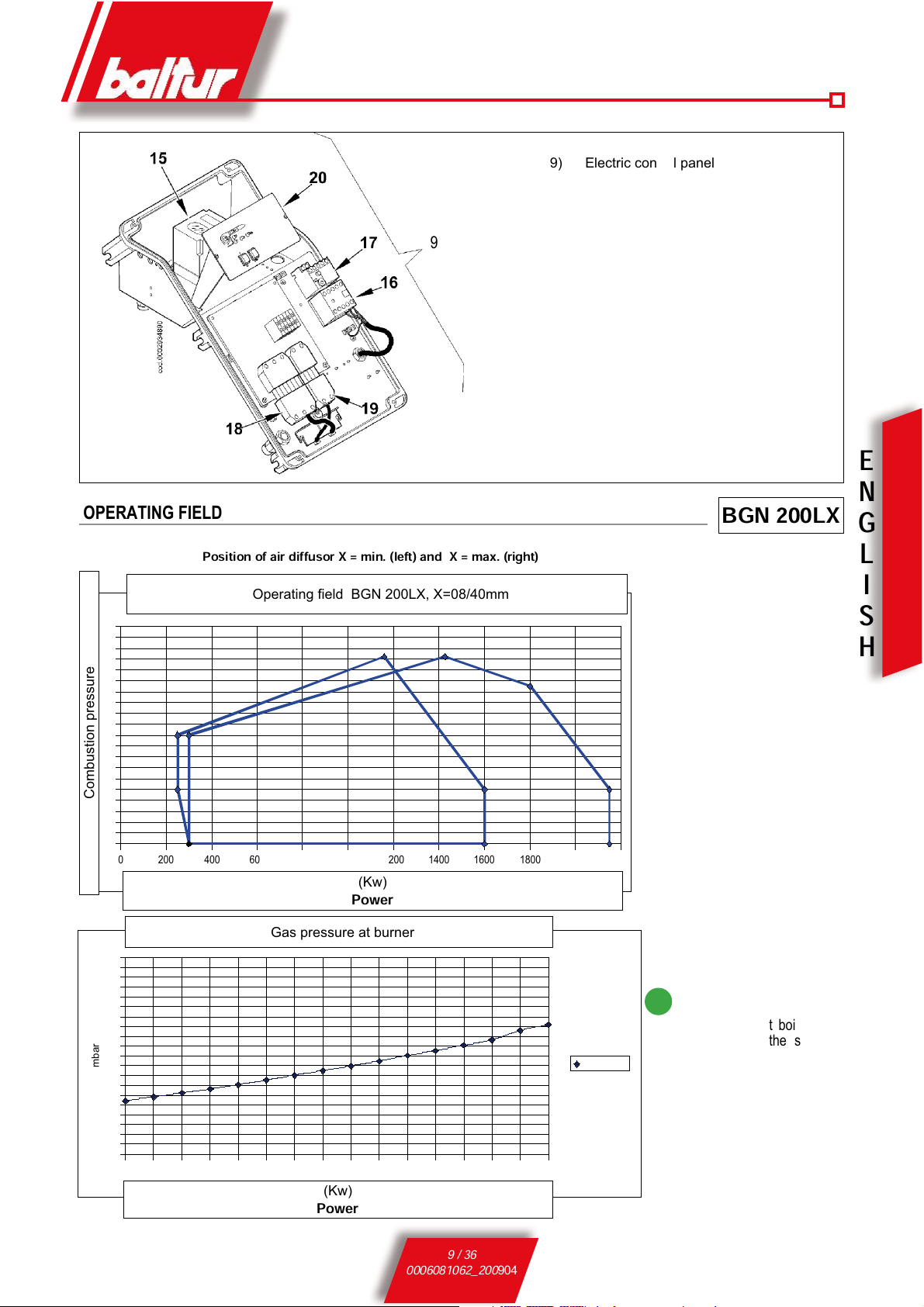
9
9) Electric control panel
15) Control box
16) Motor contactor
17) Thermal relay
18) 7-pole plug
19) 4-pole plug
20) Schematic panel
1400 1450 1500 1550 1600 1650 1700 1750 1800 1850 1900 1950 2000 2050 2100 2150
0
4
8
12
16
20
24
28
32
36
40
Gas pressure at burner
X = 40 mm
Power rate [kW]
mbar
0 200 400 600 800 1000 1200 1400
1600
1800 2000
2200
-5
-3
-1
1
3
5
7
9
11
13
15
Campo di lavoro/Operating field/Arbeitsfeld BGN 200 LX, X = 8/40 mm
Potenzialità / Power / Kapazität [kW]
Position of air diffusor X = min. (left) and X = max. (right)
BGN 200LX
Operating field BGN 200LX, X=08/40mm
(Kw)
Power
Combustion pressure
(Kw)
Power
Gas pressure at burner
OPERATING FIELD
i
The working fields are ob-
tained from test boilers corresponding to the standard
EN676 and are indicatively
for the combination burnerboiler. For correct working
of the burner the size of the
combustion chamber must
correspond to current regulations; if not the manufacturers
must be consulted.

10 / 36
0006081062_200
904
E
N
G
L
I
S
H
1200 1400 1600 1800 2000 2200 2400 2600 2800 3000 3200 3400 3600 3800
0
4
8
12
16
20
24
28
32
36
40
44
48
Pressione gas al bruciatore/Gas pressure at burner/Gasdruck am Brenner
X = 40 mm
Potenzialità / Power rate / Kapazität [kW]
mbar
0 250 500 750 1000 1250
1500
1750 2000 2250 2500 2750 3000 3250 3500 3750
4000
-5
-3
-1
1
3
5
7
9
11
13
15
17
Campo di lavoro/Operating field/Arbeitsfeld BGN 300 LX, X = 10/40 mm
Potenzialità / Power / Kapazität [kW]
Position of air diffusor X = min. (left) and X = max. (right)
BGN 300LX
Operating field BGN 300LX, X=10/40mm
(Kw)
Power
Combustion pressure
(Kw)
Power
Gas pressure at burner
OPERATING FIELD
i
The working fields are obtained from test boilers correspon-
ding to the standard EN676 and are indicatively for the combination burner-boiler. For correct working of the burner the
size of the combustion chamber must correspond to current
regulations; if not the manufacturers must be consulted.

11 / 36
0006081062_200
904
E
N
G
L
I
S
H
1000 1200 1400 1600 1800 2000 2200 2400 2600 2800 3000
3200
3400 3600 3800 4000
0
4
8
12
16
20
24
28
32
36
40
44
48
Pressione gas al bruciatore/Gas pressure at burner/Gasdruck am Brenner
X = 40 mm
Potenzialità / Power rate / Kapazität [kW]
mbar
0 250 500 750 1000 1250 1500 1750 2000 2250 2500 2750 3000 3250 3500 3750
4000
-5
-3
-1
1
3
5
7
9
11
13
15
17
Operating field BGN 390 LX, X = 10/40 mm
PFeu...power...kW
pFR...combustion pressure...mbar
Position of air diffusor X = min. (left) and X = max. (right)
BGN 390LX
Operating field BGN 300LX, X=10/40mm
(Kw)
Power
Combustion pressure
(Kw)
Power
Gas pressure at burner
OPERATING FIELD
i
The working fields are obtained from test boilers correspon-
ding to the standard EN676 and are indicatively for the combination burner-boiler. For correct working of the burner the
size of the combustion chamber must correspond to current
regulations; if not the manufacturers must be consulted.

12 / 36
0006081062_200
904
E
N
G
L
I
S
H
Position of air diffusor X = min. (left) and X = max. (right)
BGN 540LX
OPERATING FIELD
i
The working fields are obtained from test boilers corresponding
to the standard EN676 and are indicatively for the combination
burner-boiler. For correct working of the burner the size of the combustion chamber must correspond to current regulations; if not the
manufacturers must be consulted.

13 / 36
0006081062_200
904
E
N
G
L
I
S
H
GAS SUPPLY LINE
The general gas supply situation is illustrated here alongside The gas
train is EN 676 certified and is supplied separately from the burner.
A manual stop valve and a damper joint must be installed as indicated in
the diagram.
If the gas train has a pressure regulator not incorporated in a monoblock
valve, we recommend you following this practical advice on the installation of accessories on the gas piping close to the burner:
1) To prevent large pressure drops on ignition it is best if there is a
1.5 to 2 m length of piping between the point of application of the
stabilizer or pressure reducer and the burner. This pipe must have a
diameter equal to or greater than the connector to the burner.
2) For the better working of the pressure regulator it is advisable to attach
it to horizontal piping after the filter. The gas pressure regulator must
be adjusted while working at the maximum capacity actually used
by the burner. The delivery pressure must be adjusted to a figure
slightly lower than the maximum obtainable.
(that which is obtained when the regulation screw is turned almost
to the end); in the specific case, tightening the regulation screw
the regulator delivery pressure increases and when it is loosened it
decreases.
!
If the burner is equipped with gas valves, model SKP 70 .....,
the pressure regulator needs not be installed since in its
normal operation the above valve also functions as pressure
regulator.
GENERAL GAS BURNER SYSTEM
GENERAL DIAGRAM FOR
INSTALLATION OF GATE-FILTER-STABILIZER-
ANTI-VIBRATION JOINT-OPENABLE PITTING
8780GB.tif
Legend
1) Manual shut off valve
2) Anti-vibration joint
3) Gas filter
4) Minimum gas pressure switch
5) Safety valve
Gas train supplied by the manufacturer
The job of the installer
6) Pressure regulator
7) Valves seal control device (obligatory
for burner with maxmum nominal thermal output over 1200 kW)
8) Two-stage working valve
9) Control servomotor
10) Air adjustment gate
11) Air pressure switch
12) Combustion head

14 / 36
0006081062_200
904
E
N
G
L
I
S
H
COMBUSTION HEAD ASSEMBLY
Following the drawing, connect the tube on the attachment on the
flange and fix with the screw
To put in place insulation flange 2, which must be positioned
between the burner and the plate of boiler 1, the end of the combustion head must first be removed.
a) Adjust position of connector flange 4 by loosening screws 6
so that the combustion head penetrates into the combustion
chamber the amount recommended by the generator’s manufacturer.
b) Position seal insulation 3 on the tube unit.
c) Fasten the combustion head assembly to the boiler 1 using the
stud bolts, washers and the nuts provided 5.
d) With suitable material, completely seal the space between the
tube unit of the burner and the hole on the refractory plate inside
the boiler door.
0002934880
Pressure transmission pipe in
combustion chamber
Burner flange
Pressure detection pipe connection
nipple in combustion chamber
Pressure take-off in
combustion chambe
CHAMBER FOR MODEL BGN 540 LX
FOR MODELS BGN 200 LX÷BGN390 LX
N° 0002934900
Pressure detection pipe
connection nipple in combustion
chambe
Rigid pipe
fastening
screws
00029333821
Cut pipe flush with
diffusor
Pressure takeoff in
combustion
chamber
Plate and refractory
wall hole to be
drilled to Ø 12
MEASURING THE PRESSURE IN THE COMBUSTION CHAMBER
If the hole in the door is too small to allow the hose to pass and the
door has no flame inspection window it will be necessary to make
a Ø 12 in order to install the pressure take-up hose (supplied with
the burners), whose position is shown in the flange drilling-plate
drawning
s n° 0002471100 - 0002933821.
1 Boiler plate
2 Flange with insulating materials
3 Seam with insulating materials
4 Burner securing flange
5 Stud bolts, washers and nuts for fastening to the boiler
6 Nuts screws and washers to fasten flange to the sleeve
Rigid pipe that reads
combustion chamber
pressure

15 / 36
0006081062_200
904
E
N
G
L
I
S
H
ELECTRICAL CONNECTIONS
The three-phase power supply line must have a switch with
fuses. The regulations further require a switch on the burner’s
power supply line, outside the boiler room and in an easily
accessed position. For the electrical connections (line and
thermostats), follow the wiring diagram enclosed. To carry out
the connection of the burner to the power supply line proceed
as follows:
1) Remove the lid by unscrewing the 4 screws (1) in figure ,
without removing the transparent door. In this way the burner’s
electrical panel can be accessed. .
2) Slacken le screws (2) and, after removing the cable
float (3), pass the two 7 and 4 pole plugs through the hole (see
figure 2). Connect the power supply cables (4) to the contactor,
connect the cable to ground (5) and close the cable holder.
3) Reposition the cable float as in figure 3. Turn the cam (6) so
that the float exerts sufficient pressure on the two cables, then
tighten the screws that fasten the cable float. Finally, connect
the two 7 and 4-pole plugs.
!
the housings for the cables for the 7 and 4-pole plugs
are provide respectively for cable Ø 9.5÷10 mm and Ø
8.5÷9 mm, this to make sure the protection rating is
IP 54 (standard IEC EN60529) for the electrical panel.
4) To reclose the electrical panel lid, tighten the 4 screws (1)
with a torque of about 5 Nm to ensure the correct seal. At this
point, to be able to access the control panel (8), unfasten the
transparent door (7), using slight touch pressure in the direction
of the arrows in figure 4, move it the short distance to separate
it from the lid.
5) to properly resecure the transparent door on the panel proceed
as indicated in 5:position the hooks at their hooking points and
(9) slide the door in the direction indicated by the arrow until it
clicks. It is now well sealed.
Figure1
Figure 2
Figure 4
Figure 5
!
Important:
only qualified technicians may open the
burner’s electrical panel.
Figure 3
16 / 36
0006081062_200
904
E
N
G
L
I
S
H
Control box or
programmer
Safety timesPreventila-
tion time
s
Pre-
ignition
s
Post-
ignition
s
Time betwe-
en opening of
pilot valves and
opening of main
valves
s
Cut out of pilot
flame after opening
of main valves
s
Time between opening1st flame valve
and 2nd flame
valve
s
LFL 1.333 3 31,5 6 3 12 3 12
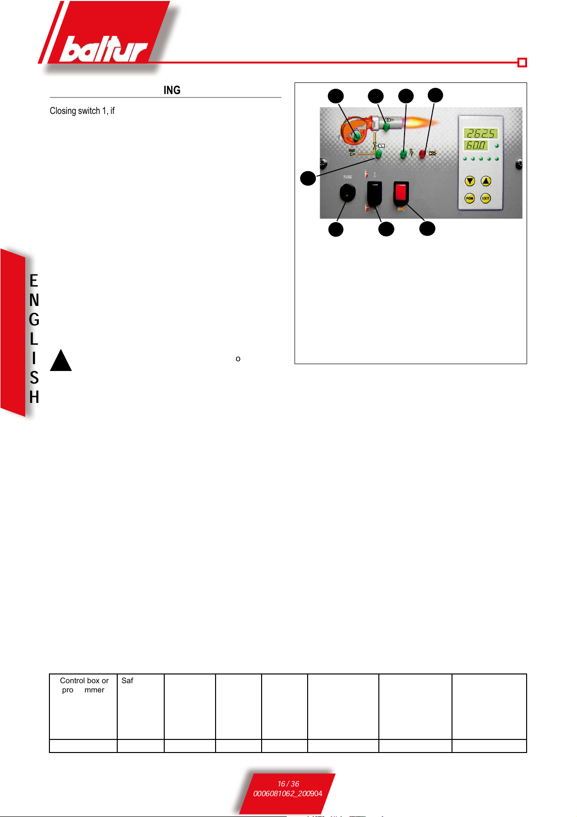
DESCRIPTION OF WORKING
Closing switch 1, if the thermostats are closed, the voltage reaches
the command and control equipment (switching on of LED 2) which
starts it working. The fan motor is thus switched on (LED 3) to carry
out the preventilation of the combustion chamber, at the same time
the air damper control servo motor moves to the opening position
corresponding to the maximum regulated power.
At the end of the preventilation stage the air damper has to be
returned to the ignition flame position. If the pressure control switch
for the ventilation air detects sufficient pressure, the ignition transformer goes on (LED 4) and, after two seconds, the main gas and
safety valves open (LED 5)
Note that:
a) The main valve has a device for the proportional adjustment of
the air to gas ratio.
b) The safety valve is an ON/OFF type.
c) The air damper is activated by an electric servo motor (see
0002933220 to 200Lx at 390Lx and 0002933490 for 540Lx), re-
member that when the burner is stopped by
the thermostat, the gate damper
is brought back by the servo motor to its closed position.
!
The gas supply at the ignition flame position must generally be greater than the minimum modulation capacity. The ignition flame position can be adjusted with
the air damper control servo motor. (see 0002933220
to 200Lx at 390Lx and 0002933490 for 540Lx).
The presence of the flame, detected by the control device
itself, permits the continuance and completion of the ignition stage with the switching off of the ignition transformer.
Subsequently the servo motor progressively opens the air
damper and the pneumatic valve allows the gas supply to
increase to its set maximum.
If there is no flame, the control box stops in its “safety lockout” (LED 7) within 3 seconds from the opening of the main
valve. In the case of safety lock-out the valves immediately
close again. To release the control box from its safety position press button 8 on the display panel.
DESCRIPTION OF MODULATION WORKING
When the burner is running at minimum capacity, if the modulation probe allows, (adjusted to a temperature or pressure value
greater than that in the boiler) the air adjustment servo motor
starts to turn causing gradual increase in combustion air supply and, consequently also of gas, up to the maximum supply
for which the burner has been set. The increase in the fan air
pressure is detected by the proportional gas valve sensor which
gradually adjusts gas supply to the change in air pressure.
The burner stays at maximum delivery until the temperature or
pressure reaches a level high enough to cause the modulation probe to turn the air adjustment servo motor in the opposite direction.
The backward rotation and consequent reduction in gas and air
supply happens at brief time intervals. With this manoeuvre the
modulation system seeks to balance the quantity of heat supplied
to the boiler with that which the boiler itself provides. The modulation probe applied to the boiler detects changes in demand and
automatically adjusts the supply of fuel and of combustion air,
switching on the servo motor with an increased or decreased rotation. If, even with fuel supply at minimum, the limit value is reached
(temperature or pressure) for which the device is set for complete
stop, (through thermostat or pressure switch) the burner is stopped
by the device.
By lowering the temperature or pressure again below the burner
stop device-triggering figure it is switched on again in accordance
with the program described in the previous paragraph.
1
2
3
4
6
8
7
5
1 Main ON-OFF switch
2 Live voltage light
3 Fan working light
4 Transformer on light
5 Gas valves working indicator light
6 Safety fuses
7 Control box lock-out light
8 Control box release button

17 / 36
0006081062_200
904
E
N
G
L
I
S
H
IGNITION AND GAS REGULATION (METHANE)
1) Make sure that the combustion head penetrates into the com-
bustion chamber by the quantity required by the manufacturer.
Check that the device that turning off the air on the combustion
head is in the proper position for the required fuel supply (the
air passage between disk and head must be sensibly reduced
in case of low fuel supply. In the contrary case, if the fuel supply
is quite high, the air passage between disk and head must be
opened). See chapter “Combustion head regulation”.
2) If not already done when connecting the burner to the gas
pipes, taking the necessary measures and opening doors and
windows, it is necessary to bleed the air contained in the pipes.
Open the union on the pipes close to the burner, and slightly
open the gas stop cock(s). Wait until you smell the typical gas
smell, and then close the cock. Wait for the necessary time,
according to the specific conditions, until the gas present in the
room is dispersed outside and then restore the connection of
the burner to the gas piping.
3) Check that there is water in the boiler and that the plant dampers
are open.
4) Make sure that the combustion product discharge can occur
freely (boiler and chimney dampers open).
5) Check that the electrical line voltage corresponds to that required for the burner, and that the electrical connections (motor and main line) are preset for the available voltage value.
Check that all electrical connections implemented on the spot
are properly executed as per our wiring diagram.
6) Apply a pressure gauge with suitable scale to the gas pressure take-off to measure the regulation value (if the expected
pressure rate allows it, it is preferable to use a water column
instrument, do not use hand instruments for low pressures).
7) Regulate the air for the ignition flame, for minimum flame and
high flame, following the instructions for regulating air damper
control electrical motor shown in the following pages. In practice, set the low flame and high flame air regulation cams to
the suitable positions according to the desired thermal power
for low and high flame.
8) By acting on the special screw for adjusti ng the gas
and air pressure ratio, on the gas valve mod. MB-VEF..,
DMV-VEF.., set the desired value (see the specific instructions for the gas valve MB-VEF.., DMV-VEF.. in the following
pages).
9) With the burner panel switch set to “0” and main circuit breaker
on, manually turn the contactor off and check that the motor
runs in the correct direction. If necessary, invert the place of two
cables of the line supplying the three-phase motor to reverse
the direction of rotation.
10) Instructions for manual mode worki ng of the burner
Combustion control can be carried out over the whole modulation range while manually controlling the MPA 22 equipment.
For this use modulation connector (B) in the diagram, which is
provided with the burner as standard. After disconnecting the
4-pole plug (A) which takes the signals from the thermostat or
the RWF 40 adjustor, insert the connector in position (B). Use
the +/- buttons to increase or reduce the gas and air supply.
After this control, put the 4-pole plug (A) back in so as to reset
automatic mode modulation
!
Note: Pre-ventilation is carried out with open air and thus,
during the same, the regulation servomotor is enabled, and
it runs a complete opening stroke up to the “maximum” set.
Only when the regulation servomotor returns to the “ignition”
position, the control box continues its ignition program by
enabling the transformer and the ignition gas valves.
During the pre-ventilation step, make sure that the air pressure
control switch changes position (from off position without pressure
detection it must switch to the off position with air pressure detection). If the air pressure switch does not detect the sufficient pressure (it does not switch position), the ignition transformer and the
flame gas valves are not enabled, and thus the control box “locks”.
To “unlock”, press the “unlock” push button(8). At the first stage there
may occur further “locks” due to:
a) The gas pipes have not been sufficiently air-bled, and thus the
gas quantity is not sufficient to allow a stable flame.
b) The “lock” with presence of flame may be caused by instability
of the same in the ionisation zone for an incorrect air/gas ratio.
Remedy is by varying the quantity of supplied air and/or gas so
as to find the correct ratio. The same problem may be caused
by a wrong air/gas distribution in the combustion head.
Remedy is by operating on the combustion head regulation device,
by adjusting the closing or opening of the air passage between
head and gas diffuser.
11) Set the burner to minimum flame (modulation servomo-

18 / 36
0006081062_200
904
E
N
G
L
I
S
H
tor set to minimum), check the quantity and appearance
of the flame making the necessary adjustments: see
instructions elating to the gas valve model MB-VEF..,
DMV-VEF.. Afterwards, check the supplied gas quantity by
reading the meter. If necessary, adjust the gas output and the
relevant combustion air by operating as described above. Then,
check the combustion with the special instruments (see chapter
“Combustion control”.
12) After adjusting the “minimum”, set the modulation switch to MAX
(maximum). The air regulation servomotor sets to “maximum”
and as a consequence, also the gas supply reaches the “maximum”. The quantity of supplied gas is then checked by reading
the meter. With burner ignited at the maximum existing output,
measure the gas flow rate by calculating the difference between
two reads performed after one minute from one another. By
multiplying the measured value by sixty, a sixty-minute flow
rate – that is, one hour – is obtained. By multiplying the hourly
output (m3/h) by the gas heat value, you obtain the delivered
power in Kcal/h, which must correspond or be very close to that
required by the burner (lower heat value for methane = 8550
Kcal/h). Avoid operating the burner if the flow rate is more than
the admissible for the boiler so as to prevent possible damages to the same. Shut down the burner after the two meter
reads.
13)To change the maximum gas output, operate on the air flow
rate regulator since the gas flow rate automatically adjust to
the air supply. Then, operate on the cam regulating the air
damper maximum aperture position (see dr. n° 0002933220 -
0002933490). Reduce the aperture angle of the air damper to
reduce the gas flow rate, and vice versa. To change the gas/air
ratio, see instruction of gas valve MB-VEF.., DMV-VEF..
14)Afterwards, check the combustion with the special instruments
and if necessary, check the existing regulation (air and optionally
gas). Check with the special instruments that the carbon oxide
(CO) percentage in the flue gas does not exceed the maximum
admissible value of 0.1% and that CO2 does not exceed 10%
for methane. (See chapter “Combustion control”)
15) After adjusting the operation to the high flame (maximum)
you must operate so that the air regulation servomotor sets
to the minimum to perform the control also in this position.
16) To set the air – and thus gas – regulation servomotor to the
minimum, the modulation switch must be pressed to MIN.
17) When the air servomotor is set to minimum, and it is necessary
to change the combustion conditions (gas/air), see the instructions for regulating gas valves model MB-VEF.., DMV-VEF..
18) It is advisable to perform the combustion control using the
instruments and, if necessary, change the previous regulation
also in some intermediate points of the modulation stroke.
19) Now, check the correct automatic modulation operation now
check correct automatic modulation operation, inserting the
boiler’s previously removed 4-pole plug.
20) The air pressure switch has the function of locking the control box
if the air pressure is not correct. The pressure switch must thus be
set to start by closing the contact (a normally open contact) when
air pressure in the burner reach a sufficient value. Note that if the
normally open contact does not close (insufficient air pressure),
the control box performs its cycle but the ignition transformer does
not start, the gas valves do not open and as a consequence, the
burner stops in lock. To check the correct operation of the air
pressure switch, set the burner to the minimum output, increase
the regulation value so as to check when it should start to immediately “lock” the burner. Unlock the burner by pressing the
special push button and restore the pressure switch regulation
to a sufficient value to detect the existing air pressure during
the pre-ventilation step. The pressure switch connection circuit
provides for the automatic control; thus, the contact provided to
be closed when at rest (fan off, and thus, absence of air pressure
in the burner) must implement this condition, or the control box
does not start (the burner remains off).
21) The gas pressure control switches (minimum and maximum),
if installed, have the function of preventing the burner from
operating when gas pressure does not range in the expected
values. From the specific function of the pressure switches, it
is evident that the minimum pressure control switch must used
the contact that is closed when it detects a higher pressure than
that to which it is set, the maximum pressure control switch must
use the contact that is closed when it detects a lower pressure
than that to which it is set. Therefore, the gas maximum and
minimum pressure switch regulation must be performed during
the burner general test and inspection, based on the pressure
measured each time. Pressure switches are electrically connected in series; thus shutting down the burner.
22) Only for BGN 540 Lx
In case of UV photoelectric cell, after at least one minute from ignition extract the photoelectric cell from its housing. When the UV
photoelectric cell is extracted from its housing, it cannot “see” the
ultraviolet radiation emitted by the flame and thus, the relevant
relay de-energises. The burner immediately shuts down in “lock”.
A light greasiness strongly affects the passage of ultraviolet
beams through the UV photoelectric cell bulb, thus preventing the internal photosensitive element from receiving the
necessary radiation for a correct operation. If the bulb is dirty
with light oil, heavy oil, etc., clean it accurately. Note that a
simple finger contact can cause a light greasiness, sufficient
to impair the UV photoelectric cell operation. The UV photoelectric cell does not “see” daylight or the light of a common
candle. A possible sensibility check can be made with a flame
(lighter, candle) or with the electrical discharge occurring
between the electrodes of a common ignition transformer.
To ensure a correct operation, the UV photoelectric cell current
value must be sufficiently stable, and must not decrease below
the minimum value required for the specific control box. Said
value is shown in the wiring diagram. It may be necessary to
experimentally search the best position by making the body
containing the photoelectric cell slide (axial or rotation movement) with respect to the fixing clamp.
23) Check the efficiency of the boiler thermostats or pressure
switches (their start must shut down the burner).

19 / 36
0006081062_200
904
E
N
G
L
I
S
H
AIR REGULATION ON COMBUSTION HEAD
(See dr. n° 0002933310)
I
Warning:
When, as in this case, the burner is provided with gas valves
model MB-VEF.., DMV-VEF.., by moving the air regulation
device on the combustion head there automatically and
unavoidably occurs a gas output variation (see chapter Valve
operation principle, model MB-VEF.., DMV-VEF..).
The combustion head is equipped with a regulation device, so as to
open or close the air passage between disk and head. By closing
the passage, it is thus possible to obtain a high pressure upstream
of the disk also for low flow rates. The high air speed and turbulence
allows a better penetration of the same into the fuel and therefore,
an excellent mixture and flame stability. It may be necessary to have
a high air pressure upstream of the disk, so as to prevent flame
pulses. This condition is indispensable when the burner operates
on pressurised combustion chamber and/or with high heating load.
From what said above it is evident that the device closing the air
on the combustion head must be set to such position as to always
obtain, behind the disk, a very high air pressure value. It is advisable
to regulate so as to have such air closure on the head as to require
the opening of the air damper regulating the flow of the burner
ventilator suction. Of course, this condition must only occur when
the burner is operating at the maximum desired output. In practice,
the regulation must start with the device that closes the air on the
combustion head in an intermediate position, igniting the burner for
an indicative regulation as explained above.
When the maximum desired output is reached, correct the position
of the device closing the air on the combustion head by moving it
forwards or backwards so as to have a suitable air flow for the output,
with suction air regulation damper sensibly open
(see dr. n° 0002933310).
!
To facilitate the combustion head regulation, see table (dr.
n° 0002933200)
When reducing the air passage on the combustion head, avoid
closing it completely, which may cause an excessive heating of
the head with a consequent quick deterioration. Perfectly adjust to
central position with respect to the disk. Note that if not perfectly
centred with respect to the disk may cause a wrong combustion and
an excessive head heating, with a consequent quick deterioration.
The check is carried out by looking through the inspection hole on
the rear side of the burner. Afterwards, tighten the screws locking the
position of the air regulation device on the combustion head.
!
Check that ignition is regular because if the controller
has been moved forward, the output air speed could be
so high as to make ignition difficult. In such a case, it is
necessary to move backwards, degree by degree, the
regulator until reaching the position in which the igni-
tion is regular and accept this new position as definitive.
We still remind you that it is preferable, for the small flame,
to limit the air quantity to the minimum indispensable to have
a safe ignition even in the most demanding case.
The minimum ionisation current for the control box to run is 6
µA. The burner flame generates a markedly higher current that
will not normally require any control box checks.
If you want to measure the ionisation current you have to con
-
nect a milliammeter in series to the ionisation electrode cable,
opening connector “C” (see diagram).

20 / 36
0006081062_200
904
E
N
G
L
I
S
H
AIR ADJUSTMENT PRINCIPLE
N° 0002933310
NOT CORRECT ADJUSTMENT
Big air passage opening
Burner’s adjustable
head
Combustion air inlet
Gate very closed
Burner’s head adjusting and
fixing knob
Burner’s adjustable
head
Air passage relatively closed
CAUTION: avoid complete closure
CORRECT ADJUSTMENT
Burner’s head adjusting and fixing knob
Combustion air inlet Gate sensibly open
MAINTENANCE
The burner does not need special maintenance. However, it is advisable to check that the gas filter is clean. It may also be necessary to
clean the combustion head. In this case, dismantle the components
of the mouth.
Be careful when assembling again, so as to prevent the electrodes
from to earth or in short circuit.
Also check that the ignition electrode spark only occurs between
the same and the drilled plate disk.

21 / 36
0006081062_200
904
E
N
G
L
I
S
H
COMBUSTION HEAD ADJUSTMENT DIAGRAM
N° 0002933200
Gas inlet
Ignition electrode
Burner fixing
flange
Burner’s head adjustment knob
Move forward to open the air passage
between the disk and the head, move
backward to close it.
X = Disk/head distance
(see diagram relative to the specific burner model)
NOTE: if the distance “X” is reduced the NOx emissions value
falls. Always adjust the distance “X” between the
minimum and maximum valuesspecified in the work
field.
ELECTRODES ADJUSTMENT DIAGRAM BGN 200 ÷ 390 LX / LX-V
1 - Ionisation electrode
2 - Ignition electrode
3 - Flame disk
4 - Gas diffuser
5 - Gas delivery pipe
N° 0002934430
MOD. A B
BGN 200 LX/LX-V 5 5
BGN 300 LX/LX-V 5 5
BGN 390 LX/LX-V 5 5
ELECTRODES ADJUSTMENT DIAGRAM BGN 540 LX / LX-V
N° 0002933850

22 / 36
0006081062_200
904
E
N
G
L
I
S
H

23 / 36
0006081062_200
904
E
N
G
L
I
S
H
CAMS REGULATION SERVONMOTOR SQM 10-20 FOR BGN - LX
N° 0002933490

24 / 36
0006081062_200
904
E
N
G
L
I
S
H
CONTROL BOX FOR GAS BURNERS LFL 1.333
serie 02
Control box for burners of average and high power, with forced
draught, intermittent service (*), 1 or 2 stages, or modulating types,
with supervision of the air pressure for controlling the air damper.
This control box bears the EC mark, in accordance with the Gas
and Electromagnetic Compatibility Directive.
* For reasons of safety, it is necessary to make at least one controlled stop every 24 hours!
As regards the standards
The following LFL1… features exceed the standards, offering a high
level of additional safety:
- The flame detector test and false flame test start immediately after
the tolerated post-combustion time. If the valves remain open, or
do not close completely after adjustment stops, a lock-out stop
is triggered at the end of the tolerated post-combustion period.
The tests will end only at the end of the pre-ventilation time of
the next start-up.
- The validity of working of the flame control circuit is checked each
time the burner starts up.
- The fuel valve control contacts are checked for wear during the
post-ventilation time.
- A built-in fuse in the appliance protects the control contacts from
any overloads that may occur.
As regards the burner control
- The equipment allows operation with or without post-ventilation.
- Controlled activation of the air damper to ensure pre-ventilation
with nominal airflows. Positions checked: CLOSED or MIN (position of ignition flame on start-up); OPEN at the beginning and
MIN at the end of the pre-ventilation time. If the servomotor does
not position the air damper at the points described, the burner
does not start-up.
- Ionization current minimum value = 6mA
- UV cell current minimum value = 70mA
- Phase and neutral must not be inverted.
- Any place may be used for installation and assembly (IP40
protection).

25 / 36
0006081062_200
904
E
N
G
L
I
S
H
Electrical connections
The burner manufacturer’s diagram is valid for the relief valve connections.
Legend
For the entire catalogue sheet
a Limit switch commutation contact for air damper OPEN
position
AL Remote signalling of lock-out stop (alarm)
AR Main relay (operating relay) with “ar…” contacts
AS Appliance fuse
BR Lock-out relay with “br…” contacts
BV Fuel valve
bv... Control contact for gas valve CLOSED position
d… Remote control switch or relay
EK… Lock-out push-button
FE Ionization current probe electrode
FR Flame relay with “fr…” contacts
GP Gas pressure switch
H Main switch
L1 Fault indicator light
L3 Ready for operation indicator
LK Air damper
LP Air pressure switch
LR Power regulator
m Auxiliary commutation contact for air damper MIN position
M… Motor fan or burner
NTC NTC resistor
QRA.. UV probe
R Thermostat or pressure probe
RV Fuel valve with continuous regulation
S Fuse
SA Air damper servomotor
SB Safety limiter (temperature, pressure, etc.)
SM Programmer synchronous motor
v In the case of servomotor: auxiliary contact for consensus
for fuel valve depending on air damper position
V Flame signal amplifier
W Thermostat or safety pressure switch
z In the case of servomotor: limit switch commutation con-
tact for air damper CLOSED position
Z Ignition transformer
ZBV Pilot burner fuel valve
• Valid for forced draught burners, with obe tube
•• Valid for pilot burners with intermittent operation
(1) Input for increasing operating voltage for UV probe (probe
test)
(2) Input for forced energizing of flame relay during functional
test of flame supervision circuit (contact XIV) and during
safety time t2 (contact IV)
3
) Do not press EK for more than 10 seconds

26 / 36
0006081062_200
904
E
N
G
L
I
S
H
Notes on the programmer
Programmer sequence
Times Legend
time (50 Hz) in seconds
31.5 t1 Pre-ventilation time with air damper open
3 t2 Safety time
- t2’ Safety time or safety time with burners that use pilot
burners
6 t3 Short pre-ignition time (ignition transformer on terminal
16)
- t3’ Long pre-ignition time (ignition transformer on terminal
15)
12 t4 Time between beginning of t2’ and valve consensus on
terminal 19 with t2
- t4’ Time between beginning of t2’ and valve consensus on
terminal 19
12 t5 Time between end of t4 and consensus at power regu-
lator or at valve on terminal 20
18 t6 Post-ventilation time (with M2)
3 t7 Time between consensus for start-up and voltage at
terminal 7 (start delay for fan motor M2)
72 t8 Start-up duration (without t11 and t12)
3 t9 Second safety time for burners that use pilot burners
12 t10 Time from start-up to beginning of air pressure control
without air damper travel time
t11 Air damper opening travel time
t12 Air damper in flow flame position (MIN) travel time
18 t13 Permitted post-combustion time
6 t16 Initial delay of consensus for air damper OPENING
27 t20 Time up to automatic closure of programmer mechanism
after burner start-up
Output signals on terminal

27 / 36
0006081062_200
904
E
N
G
L
I
S
H
Stop indications
NOTE:
With voltages at 60 Hz, the times are reduced by about 20%.
t2’, t3’, t3’:
These times are valid only for series 01 or LFL1.335, LFL1.635,
LFL1.638 burner control and command equipment.
They are not valid for types of Series 032, since they involve simultaneous activation of cams X and VIII.
Working
The above diagrams illustrate both the connection circuit and the
sequencer mechanism control program.
A Consensus for start-up by means of installation thermostat or
pressure switch “R”.
A-B Start-up program
B-C Normal burner operation (on the basis of “LR” power regulator
control commands)
C Stop controlled by “R”
C-D Return of programmer to start-up position “A”, post-ventilation.
During periods of inactivity of the burner, only the command
outputs 11 and 12 are powered, and the air damper is in the
CLOSED position, determined by limit switch “z” of the air
damper servo motor. During the probe test and false flame
test, the flame supervision test is also powered (terminals
22/23 and 22/24).
Safety standards
• In association with the use of QRA…, earthing of terminal 22
is compulsory.
• The power cables must conform to existing national and lo-
cal standards.
• LFL1… is a safety device, and it is therefore forbidden to
open it, tamper with it or modify it!
• The LFL1… device must be completely insulated from the
mains before carrying out any operations on it!
• Check all the safety functions before activating the unit or
after replacing a fuse!
• Provide protection against electric shock on the unit and all
electric connections. This is ensured by following the assembly instructions correctly!
• During operation and maintenance, prevent infiltration of
condensate into the command and control equipment.
• Electromagnetic discharges must be checked on the applica-
tion plan.
Control program in the event of stopping, indicating position of
stop
As a rule, in the event of any kind of stop, the fuel flow is cut off
immediately. At the same time, the programmer remains immobile,
as does the switch position indicator. The symbol visible on the
indicator reading disk indicates the type of fault.
◄ No start-up, because of failure in closing of a contact or
lock-out stop during or at the end of the command sequence
because of external lights (for example: flames not extinguished, loss at the level of the fuel valve, defects in the
flame control circuit, etc.)
▲ Start-up sequence stops, because the OPEN signal was not
sent to terminal 8 by limit switch contact “a”. Terminals 6, 7
and 15 remain powered until the defect is eliminated.
P Lock-out stop, because of lack of air pressure signal.
Any lack of pressure from this moment onwards will cause
a lock-out stop!
▄ Lock-out stop because of flame detection circuit malfun-
ction.
▼ Start-up sequence stops, because the position signal for
low flame was not sent to terminal 8 by auxiliary switch
“m”. Terminals 6, 7 and 15 remain powered until the fault is
eliminated.
1 Lock-out stop, due to lack of flame signal at the end of the
first safety time.
2 Lock-out stop, because no flame signal was received at the
end of the second safety time (main flame signal with pilot
burners at intermittent operation).
▌ Lock-out stop, due to lack of flame signal during burner
operation.
If a lock-out stop occurs at any moment between the start and preignition without a symbol, the cause is generally to be attributed
to a premature or abnormal flame signal caused, for example, by
self-ignition of a UV tube.
LFL …, Series 01 LFL …, Series 02
a-b Start-up program
b-b’ “Trips” (without contact confirmation)
b(b’)-a Post-ventilation program

28 / 36
0006081062_200
904
E
N
G
L
I
S
H
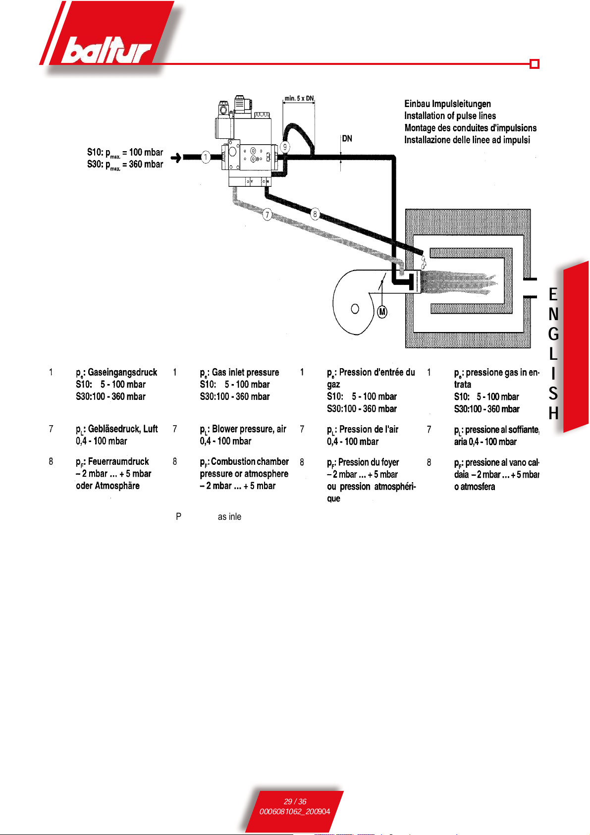
DUNGS mod. MB-VEF BO1
N° 0002910621
- INSTRUCTIONS FOR MONOBLOC VALVE WITH CONTINUOUS MODULATION OPERATION
1
Electrical connection for pressure switch (DIN 43650))
2
Electrical connection for valves (DIN 43 650)
3
Pressure switch
4
Input flange
5
Test point connection G 1/8 upstream of filter, possible on both sides.
6
Filter (below cover)
7
Type plate
8
G 1/8 pressure connection for pL blower pressure
9
Setting screw, ratio V
10
Test point connection G 1/8 downstream of filter possible of both sides
11
Test point connection M4 down- stream of V2
12
Setting screw, zero point adjustment N
13
G 1/8 pressure connection for p F furnace pressure
14
G 1/8 pressure connection for p Br
burner pressure
15
Output flange
16
Test point connection G 1/8 downstream of V1, possible on both sides
17
Operation display V1, V2 (optional)
18
Pulse line
Pressure taps
1,3,4,6 Screwed sealing plug G 1/8
2 Measuring nozzle
5 Screwed sealing plug M4
7,8,9 Female thread for pulse lines G 1/8 P
L
, P
F
0 Filter cup
29 / 36
0006081062_200
904
E
N
G
L
I
S
H
Pe Gas inlet pressure

30 / 36
0006081062_200
904
E
N
G
L
I
S
H
DUNGS mod. DMV-VEF 5065/11 - 5125/11
N° 0006080717
Rev. 2002/06
INSTRUCTIONS FOR DOUBLE SOLENOID VALVE GAS-AIR-RATIO CONTROL

31 / 36
0006081062_200
904
E
N
G
L
I
S
H

33 / 36
0006081062_200
904
E
S
P
A
Ñ
O
L
DUNGS mod. MB-VEF BO1 / DMV-VEF
TARADO DEL GRUPO DE REGULACIÓN - PRESIÓN
!
The pressure – adjustment unit is factory set. Settings should
then be adapted on site to suit the needs of the system.
La válvula modulante mod. MB-VEF B01 opera aumentando
automáticamente la cantidad de salida del gas si aumenta el caudal del
aire, y reduce automáticamente la cantidad de salida del gas si se reduce el
caudal del aire. Por consiguiente, la cantidad de salida de gas al “mínimo“ y
al “máximo” del quemador tiene que ser regulada exclusivamente regulando
el “mínimo” y el “máximo” del aire de combustión. Prácticamente se opera
sobre las dos “levas” que regulan el mínimo y el máximo del servomotor de
regulación del aire. Teniendo en cuenta este principio, aconsejamos que
operen como indicamos a continuación para regular el quemador. Encienda
y mantenga el quemador al mínimo de la modulación (válvula modulante
abierta al mínimo), controle el contenido de CO
2
o O2 y CO en los humos
y, si fuera necesario, ajuste con el tornillo de regulación ”N” la relación gas/
aire, obtenida con el desplazamiento paralelo de las curvas características
(véase el diagrama).
!
NOTA:Encienda y mantenga el quemador al mínimo de la modula-
ción (válvula modulante abierta al mínimo), controle el contenido
de CO
2
o O2 y CO en los humos y, si fuera necesario, ajuste con
el tornillo de regulación ”N” la relación gas/aire, obtenida con el
desplazamiento paralelo de las curvas características (véase el
diagrama).
!
NOTA:Para disminuir la cantidad de aire respecto al gas y por lo tanto
para aumentar el porcentaje de CO2 regule ‘N” hacia los valores positivos (+). Para aumentar la cantidad de aire respecto al gas y por
lo tanto para disminuir el porcentaje de CO
2
, regule “N” hacia los
valores negativos (-). Ponga el quemador al máximo de la modulación, mida el contenido de CO2 o O2 y CO en los humos y, si fuera
necesario, ajuste la relación tarada con el tornillo “V” hasta que el
valor medido sea óptimo.
!
NOTA:Para disminuir la cantidad de aire respecto al gas y por lo
tanto para aumentar el porcentaje de CO2 regule “V” hacia relaciones más grandes. Para aumentar la cantidad de aire respecto
al gas y por lo tanto para disminuir el % de CO
2
regule “V” hacia
relaciones más pequeñas (véase el diagrama). Una vez regulado
el máximo de la modulación, vuelva a la posición de mínimo y
controle las regulaciones efectuadas anteriormente. Si fuera ne-
cesario, corrija de nuevo el punto “0” con la regulación “N”.
!
NOTA: Cuando ha sido necesario efectuar una modificación
paralela de la curva para obtener con baja carga (modulación
al mínimo) valores buenos de CO2 o O2, hay que controlar de
nuevo la regulación de la relación gas-aire y, si fuera necesario,
variar la relación gas/aire con el tornillo “V”.
ATENCIÓN: Atendiendo a lo que hemos indicado, es evidente que la
variación de presión del aire que se obtiene en el quemador
mediante el dispositivo de regulación del aire en la cabeza de
combustión (variación de la sección de paso del aire) determina
automática e inevitablemente una variación de cantidad de salida
de gas.
Alojamiento para la llave hexagonal
hueca de 2,5 mm.
N° 0002910621 /
0006080717
Rev. 22/10/2004
Exemple : En réduisant la section de passage de l’air entre la tête et le
disque, nous obtenons une augmentation de la pression de l’air
dans le brûleur et une réduction de la distribution de l’air dans
le foyer, par conséquent, la vanne gaz MB-VEF B01 détecte
l’augmentation de pression et augmente la distribution du gaz,
il est alors indispensable de corriger (réduire) la distribution de
gaz en agissant sur les dispositifs correspondants présents sur
la vanne.
TORNILLOS DE REGULACIÓN PUNTO CERO “N“
Y RELACIÓN GAS/ARIA “V“

34 / 36
0006081062_200
904
E
S
P
A
Ñ
O
L
p
L
AIR
p
Br
GAS
p
F
Combustion
atmosfere
V
min./mini
max/maxi
N
± 1 mbar
p
L
max/maxi = 100 mbar
V
max/maxi = 3:1
p
F
max/maxi = +5 mbar
pBrmax/maxi = 100 mbar
p
L
min./mini = 0,4 mbar
pBrmin./mini = 0,5 mbar
pFmin./mini = -2 mbar
V
min./mini = 0,75:1
V
= pBr: p
L
MB-VEF
Einstellbereich
Setting range
Plange de réglage
Campo di regolazione
Corrección punto cero ± 1 mbar
Posibilidad de regulación
Presión efectiva en el quemador
Presión efectiva en el soplador
Magnitud secuencial
Magnitud guía
Rango de regulación

35 / 36
0006081062_200
904
E
S
P
A
Ñ
O
L
ANOMALÍAS EN EL FUNCIONAMIENTO DE LOS QUEMADORES DE GAS Y SOLUCIONES EN DOS ETA
-
PAS
ANOMALÍA CAUSA POSIBLE SOLUCIÓN
Llama encendida,
el aparato se bloquea (testigo rojo encendido).
Avería relacionada con el dispositivo de
seguridad de la llama.
1) El transformador de encendido interfiere
con la corriente de ionización.
2) El sensor de la llama está averiado (sonda
de ionización o célula UV).
3) El sensor de llama está mal colocado
(sonda de ionización o célula UV).
4) La sonda o el cable de ionización están
puestos a tierra.
5) La conexión eléctrica del sensor de la llama
está interrumpida.
6) El tiro es insuficiente o el extractor de
humos está obstruido.
7) El disco de la llama o el cabezal de com-
bustión están sucios o gastados.
8) La célula UV está sucia o grasienta.
9) El aparato está averiado.
10) Falta de ionización.
1) Invertir la alimentación (230 V) del tran-
sformador de encendido y medir con un
microamperímetro analógico.
2) Sustituir el sensor de la llama.
3) Corregir la posición del sensor de la llama
y medir con un microamperímetro analógi-
co.
4) Comprobar visualmente y con una herramienta.
5) Restablecer la conexión.
6) Controlar si el extractor de humos de la
caldera y el paso del racor de la chimenea
están libres.
7) Controlar y, si es necesario, sustituirlos.
8) Limpiar.
9) Sustituirlo.
10) Si la puesta a tierra del quemador no
funciona, la corriente de ionización no se
efectúa. Controlar la puesta a tierra del
borne del aparato y del sistema eléctrico.
Llama apagada, el gas sale, el aparato se
bloquea (testigo rojo encendido).
Avería relacionada con el circuito de
encendido.
1) Avería en el circuito de encendido.
2) El cable transformador del encendido
descarga a tierra.
3) El cable transformador del encendido está
desconectado.
4) El transformador de encendido está averiado.
5) La distancia entre el electrodo y la puesta
tierra es incorrecta.
6) El aislante está sucio por lo que el electrodo descarga a tierra.
1) Controlar la alimentación del transformador
de encendido (230 V) y el circuito de alta
tensión (electrodo a tierra o aislante roto
debajo del borne de bloqueo).
2) Sustituirlo.
3) Conectarlo.
4) Sustituirlo.
5) Establecer la distancia correcta.
6) Limpiar o sustituir el aislante y el electrodo.
Llama apagada, el gas sale, el aparato se
bloquea (testigo rojo encendido).
1) La mezcla de aire y gas es incorrecta.
2) La tubería del gas aún contiene aire (primer
encendido).
3) La presión del gas es insuficiente o excesiva.
4) El paso del aire entre el disco y el cabezal
está demasiado cerrado.
1) Corregir la mezcla de aire y gas (probablemente hay demasiado aire o poco gas).
2) Purgar la tubería del gas.
3) Controlar la presión del gas máxima en el
momento del encendido (si es posible,
utilizar un manómetro por columna de
agua).
4) Adaptar el paso entre disco y el cabezal.

36 / 36
0006081062_200
904
E
S
P
A
Ñ
O
L

149 / 162
0006081062_200904

150 / 162
0006081062_200904

151 / 162
0006081062_200904

152 / 162
0006081062_200904
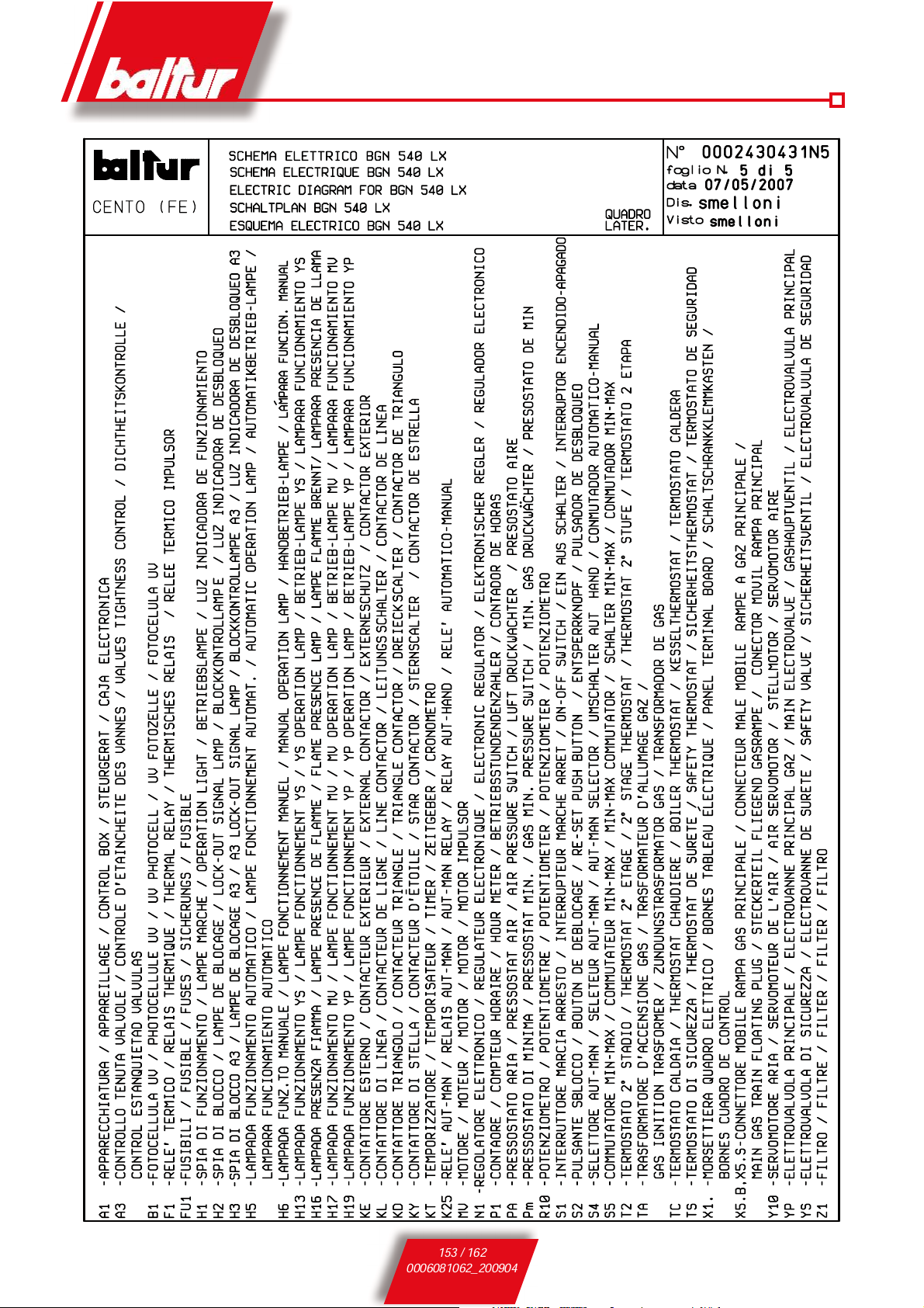
153 / 162
0006081062_200904

154 / 162
0006081062_200904

155 / 162
0006081062_200904

156 / 162
0006081062_200904

157 / 162
0006081062_200904

158 / 162
0006081062_200904
 Loading...