

Page 1
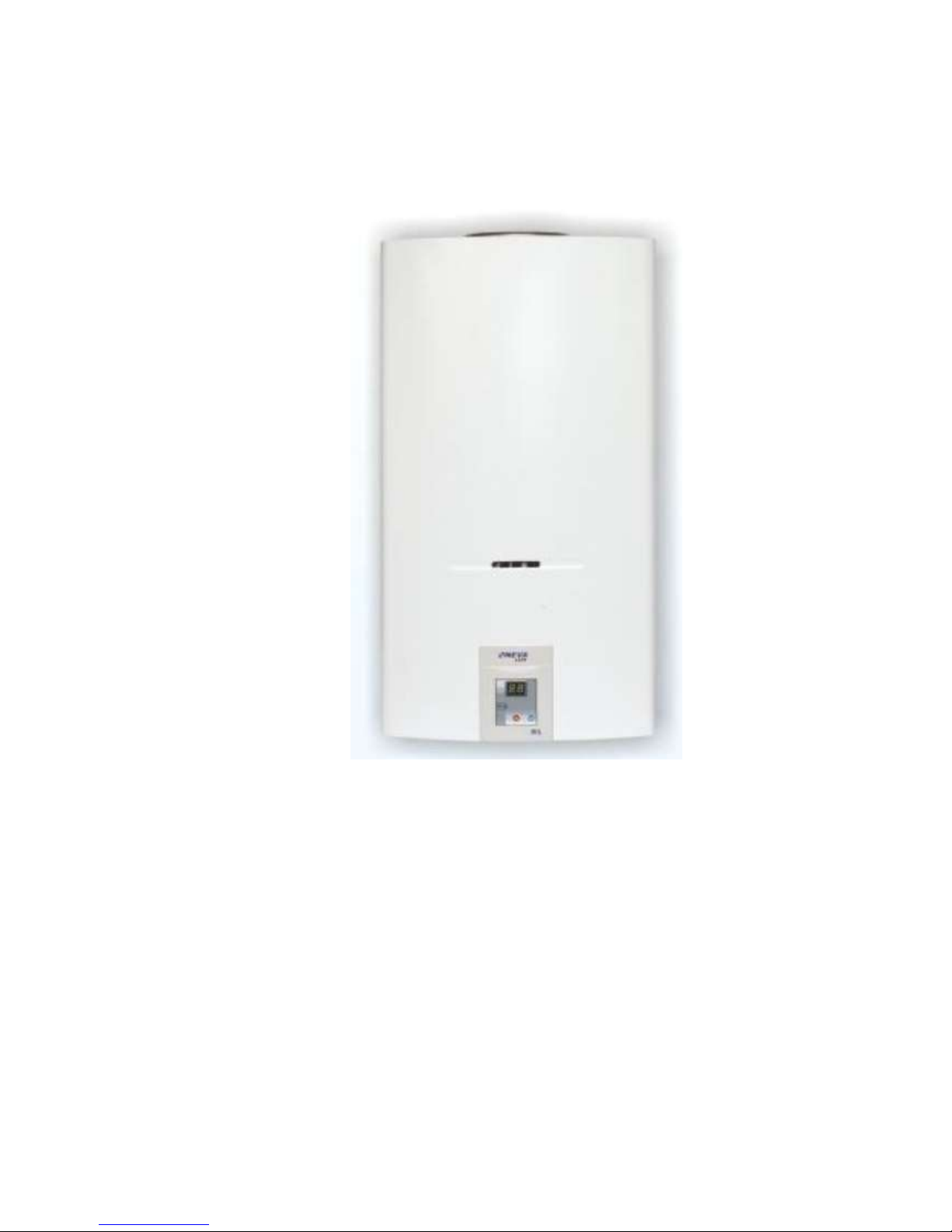
BaltGaz NEVA
LUX
INSTANTANEOUS GAS WATER HEATER FOR DOMESTIC USE
BaltGaz NEVALUX-6011
TU 4858-008-26985921-2008
USER’ S MANUAL
(TOGETHER WITH THE INSTRUCTIONS ON MOUNTING, TECHNICAL
SERVICE AND REPAIR OF THE WATER HEATER)
3273-00.000-01 RE
Page 2

4
Dear customer,
Thank you for choosing our water heater.
You have purchased an instantaneous water heater with electronic control system, providing automatic
ignition of the ignition and main burners at opening the hot water tap.
When purchasing the appliance please check:
Scope of delivery (p.2.3. page 5)
Compatibility of pressure and type of gas (NG or LPG) used by you with the type of gas indicated in
the Acceptance certificate and in the table on the appliance.
You should also require from the selling organization to fill in the warranty repair coupons.
When purchasing the appliance against a credit, the payment schedule should be drawn up with
indication of full due and payable amount. The payment schedule should be signed by the Customer with the
date indicated and with print full name.
The present user’s manual is combined with the mounting, service and repair instructions and contains
information about the rules of the appliance’s exploitation and treatment, information about technical service
and the order of the water heater’s installation. Following the above-mentioned rules will provide long-term
failure-free and safe operation of the appliance. Please get carefully acquainted with this manual and follow
its instructions.
Best regards
Armavirsky Plant of Gas Equipment, Ltd.,
Armavir
Telephone number of the unified technical support Service 8 800 555 40 35
(free call on the territory of Russian Federation, working hours of the service: twenty-four-hour)
Installation of the appliance, instruction of the owner on the appliance’s operating principles and rules of
exploitation, technical service, failure elimination and repair are effectuated only by a specialized service
organization.
Checking and cleaning of the exhaust flue, repair of water communications are performed by residential
operational services upon request of the appliance’s owner.
The responsibility for safe exploitation of the appliance and its maintenance in appropriate condition is on its
owner.
Non-compliance with the safety measures and installation rules, rules of use and technical service stated in this
manual can cause fire, burn, gas poisoning or poisoning with carbonic oxide (CO).
Armavirsky Plant of Gas Equipment Ltd. Is constantly working on improvement of output products and
reserves the right for insertion of necessary changes in the water heater’s construction. The following
changes might not be displayed in the user’s manual.
29.03.2013
Page 3

5
TABLE OF CONTENTS
1. SAFETY MEASURES
INDICATION…………………………………………………………………………………………..………...3
2. DESCRIPTION AND OPERATION OF THE
APPLIANCE……………………………………………………………………………………………….…..... 3
2.1. Appliance’s purpose……………………………………………………………………………………….….3
2.2. Technical characteristics….………………………………………………………………….…………..……4
2.3. Supply package…………………………………………………………………………………….… 5
2.4. Overall and connection dimensions of the appliance………………….……………………………..... 5
3. USAGE OF THE APPLIANCE…………………………………………………………………….……..…..7
3.1. Putting the appliance into
operation……………….…………………………………………………………………………………..….…..7
3.2. Water temperature regulation…………………………………..……………………………………….……7
3.3. Switching the appliance
off…………………………………………………………………………………………………………….…..8
3.4. Replacing the power
element………………………………………………………………………….………………………….…..….8
3.5. Protection from freezing…………………………………………………………………….……….. 9
3.6. Actions in emergency
situations……………………………………………………………………….………………………….….......9
4. APPLIANCE TREATMENT.………………………………………………………………………..……...….9
4.1.Examination……………………………………………………………………………….………….… 9
4.2.Treatment…………………………………………………………………………………………...….. 9
5. RULES OF TRANSPORTATION AND
STORAGE……………………………………………….…………………………………………….…….…..10
6. SAFETY MEASURES……………………………………………………………………….………… 10
7. APPLIANCE INSTALLATION…………………………………………………………...……….…… 10
7.1.Place and scheme of installation……………………………………………………………………………. 10
7.2. Mounting the appliance……………………………………………………………………………..………..11
7.3. Connecting the appliance to the water supply system ………………………………………..………..…..12
7.4. Connecting the appliance to the gas
system……………………………………………………………………………………………………………..12
7.5. Connecting the appliance to the LPG cylinder……………………………………………..…………. 12
7.6. Rules of flexible hoses installation…………………………………………………………………..……. 13
7.7. Connecting the appliance to the exhaust flue………………………………………………………….. 14
7.8. Installation of the power
element……………………………………………………………………………………………………..……..15
7.9. Checking the appliance………………………………………………………………………………… 15
7.10. Rendering the appliance to another type and pressure of gas………………………………………...…….15
8. CONSTRUCTION AND OPERATION CONTROL OF THE
APPLIANCE……………………………………………………………….……………………………… 16
8.1. Construction of the
appliance…………………………………………………………………………………………………...……..15
8.2. Operation of the appliance………………………………………………………………………………….. 19
9. POSSIBLE FAILURES AND METHODS OF THEIR
ELIMINATION……………………………………………………………….……………………….…… 22
10. GENERAL INSTRUCTIONS…………………………………………..……………………...……... 25
11. HANDING THE APPLIANCE OVER TO THE
CUSTOMER…………………………………………………………………………………………………… 25
12. TECHNICAL SERVICE…………………………………………………………..………………………....26
12.1. Cleaning the main and ignition
burner…………………………………………………………………….…………………………...…………..26
12.2. Cleaning the heat exchanger……………………………………………………………………………….. 26
Page 4

6
12.3. Cleaning and connection of the contacts……………………………………………………...……. 26
12.4. Sealings replacement………………………………………………………………………..……….26
12.5. Checking the appliance's gas and water systems on airtightness…………………………………………………………………………………..…………….….27
12.6. Checking of the thermo relay's (draught sensor's) working
capacity……………………………………………………………………………………………....…….27
12.7. Checking of the water temperature sensor's working capacity……………..…………………..……27
12.8. Unscheduled cleaning of the
appliance…………………………………………………………………………...…………………..…..27
13. WORKS ORDER AT THE APPLIANCE’S REPAIR AND COMPONENTS
REPLACEMENT……………………………………………………………………………………….. 27
13.1. Casing removal………………………………………………………………………………….. 27
13.2. Ignition burner replacement…………………………………………………………………….…. 27
13.3. Main burner replacement…………………………………………………………………………….27
13.4. Heat exchanger replacement…………………………………………………………………….. 28
13.5. Battery section replacement………………………………………………………………………. 28
13.6. Water and gas unit replacement……………………………………………………………………. 28
13.7 Replacement of the water and gas unit’s valve block…………………………………………….….28
13.8. Replacement of the water and gas unit’s water unit………………………………………………...28
13.9. Replacement of the water unit membrane (membrane assembled with the
plate)………………………………………………………………………………………………...…….28
13.10. Replacement of the water temperature
sensor…………………………………………………………………………………………………..….29
13.11. Replacement of the pipe of cold water supply to the heat
exchanger……………………………………………………………………………….…………. 29
13.12. Replacement of the pipe of hot water outlet from the heat
exchanger…………………………………………………………………………………….…….. 29
13.13. Replacement of thermo relay (draught sensor)…………………………………………….. 29
13.14. Replacement of the electronic control block…………………..………………..………….. 29
13.15. Replacement of the plug or flame sensor……………………………………….…………. 29
13.16. Replacement of micro switch (water flow sensor)…………………………………….……. 29
ANNEX I. scheme of the appliance with separated
components……………………………………………………………………………..…………... 33
Page 5

7
1. SAFETY MEASURES INDICATION
1.1. In order to avoid accidents and the appliance’s breakdown it is prohibited to:
Install and put the appliance into operation by yourself;
Effectuate the appliance’s regulation without being acquainted with the present user’s manual;
Close the grid or gap in the bottom part of the door or wall (in the premise where the appliance is installed)
intended for air inlet necessary for gas combustion;
Use the appliance if there is a lack of draught in the exhaust flue;
-Use the appliance in case of absence or discharge of the power element
Use the appliance when it is out of order;
Dismantle and repair the appliance by yourself;
Insert changes into the appliance’s construction;
Leave the working appliance unkept;
Touch the casing of the operating appliance in the area of viewing window and in close proximity to it,
and also the combustion products output pipe next to the gas removal device as the temperature of these
surfaces might exceed 100 oС;
1.2 In case of possibility of water freezing in the water system of the appliance it is necessary to drain the
water out of the appliance.
1.3 In case of detection of the appliance’s operation failure it is necessary to address to the special service
organization and not to use the appliance until troubleshooting.
1.4 At the appliance’s normal operation and when the gas pipeline is in good order there should not be any
smell of gas in the premise.
IF YOU FEEL THE SMELL OF GAS:
a) Close the gas supply tap, that is located on the gas pipeline next to the appliance;
b) Open the windows and doors in order to ventilate the premise, providing maximum fresh air inlet;
c) Do not switch the electric light or any other electric appliances on or off;
d) Do not use open fire (lighters, matches etc.)
e) Do not use the telephone in a gas-polluted premise;
f) Do not smoke;
g) Call the gas facility emergency operation service immediately.
Non-compliance with the above-listed safety measures may lead to poisoning with gas or carbonic oxide (CO)
from the incomplete gas combustion products.
The first symptoms of poisoning are: heaviness in the head, strong palpitation, buzzing in the ears, swimming of
the head, general weakness. Later nausea, vomiting, scant of breath and disordered motor function may appear.
The injured person may suddenly lose consciousness.
Page 6

8
In order to provide first aid it is necessary to:
a) Bring the injured person into the fresh air;
b) Unclasp clothes that constrain breath;
c) Give household ammonia to smell;
d) To cover warmly, but not letting to fall asleep and call the ambulance.
e) In case if there is no breath you must immediately bring the injured person to a warm premise
with fresh air and make resuscitation not stopping it before the doctor arrives.
.2.DESCRIPTION AND OPERATION OF THE APPLIANCE
2.1. Appliance’s purpose
2.1.1. Instantaneous domestic gas water heater «BaltGaz NEVALUX-6011» hereinafter referred to as
“Appliance” is manufactured according to TU 4858-008-26985921-2008 (GOST Р 51847-2009) standard and
designed for water heating for sanitary purposes (washing the dishes, laundry, bathing) in the apartments and
individual residential premises.
2.1.2. The appliance is designed for working on NG in accordance with GOST 5542-87 standard or LPG in
accordance with GOST 20448-90 (appliance category in accordance with GOST Р 51847-2009 – II
2Н+3B/P
)
standard. The company- manufacturer releases the appliance adjusted to the particular type of pressure and gas
indicated in the table on the appliance and in the Acceptance certificate.
The appliances are designed for connecting to the exhaust flue for removal of combustion products out of
the premise, they are saturated with a draught stabilizer and draught sensor, have no fan in the tract for removing
combustion products and by the air inlet (type of appliance in accordance with GOST Р 51847-2009 standard –
В
11BS
).
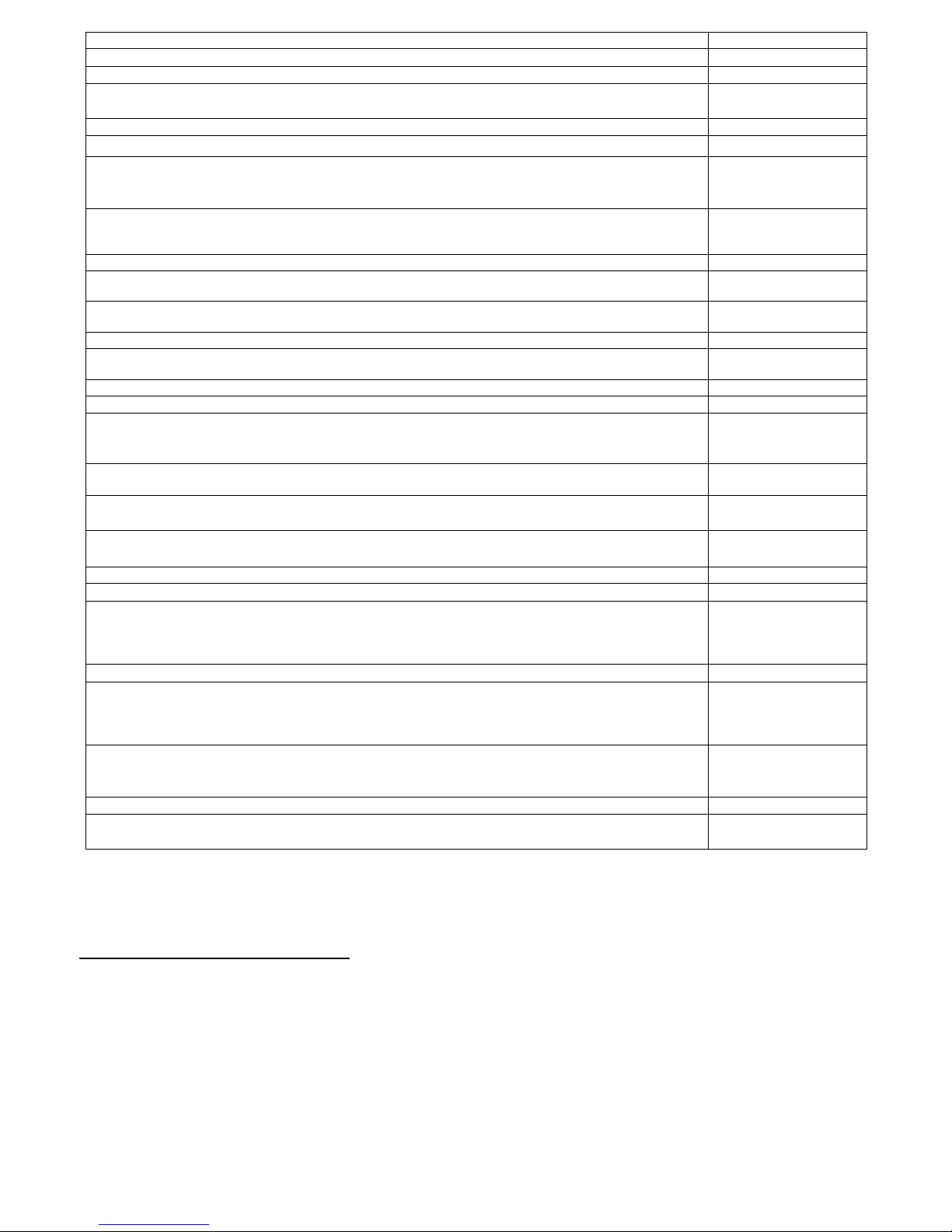
2.2. Technical characteristics Table1
Page 7
9
* Reference parameters for p. 2.2.13, 2.2.14 - at water pressure at least 250 kPа by the inlet into the operating
appliance;, for. 2.2.26 - when using alkaline power elements with high energy output ratio.
Main particularities of the appliance:
- The appliance is automatically switched on when the hot water tap is opened (at water consumption
more than 2,5 l/min);
- The ignition burner automatically switches off after the main burner ignites;
- The appliance keeps (within the bounds of its heating effect) the set hot water temperature when water
consumption, inlet water temperature and gas pressure is changed:
- On the digital display there is shown the temperature of water running out of the appliance and the
temperature set by pressing the control buttons;
2.2.1. Rated heating power, kW
21
2.2.2. Rated heating effect, kW
18
2.2.3. Rated heating power of the ignition burner, kW, not more than,
0,17
2.2.4. Gas type
NG/LPG
2.2.5. Family; gas group
2nd ; Н / 3rd ; B/P
2.2.6. Rated gas pressure, kPа (mm w.g.):
nd
1,3 (130)
2.2.7. Rated gas consumption , m3/h
nd
2,2
2.2.9. Supplied water pressure for the appliance’s normal operation, kPa
30...600
2.2.10. Maximal water pressure (at water’s heat expansion the pressure must not exceed
1000
2.2.12. Minimal water pressure (for ignition), not more than, kPa
15
2.2.13. Water consumption at heating for Δ=40 °С, l/min
7
2.2.14. Water consumption at heating for Δ Т=25 °С, l/min
11,0*
2.2.15. Required rarefaction in the exhaust flue, Pа (mm w.g.),
Not less than
2.2.16. Mass consumption of combustion products NG/ LPG at rated heating power,
7,4/8,0
2.2.17. Average temperature of combustion products, С
150
2.2.18. Minimal allowable inlet gas pressure at the appliance’s operation, Pa (mm w.g.)
784 (80)
2.2.19. Combustion products temperature, °С, not more than
110
2.2.20. Appliance’s ignition type
electronic
2.2.21. Appliance’s overall dimensions, mm:
Height
565
290
2.2.22. Weight of appliance, NET /GROSS, kg, not more than
10,5/11,5
2.2.23. Diameter of the nozzles of the main burner, mm :
NG 1,3 kPа (G20, 2nd family, group Н)
1,28
1,14
2.2.24. Diameter of the nozzles of the ignition burner, mm :
NG (G20, 2nd family, group H)
0,55
0,35
2.2.25. Type and voltage of power element, V
LR20; 1,5 В
2.2.26. Continuous operation with one power element, h
250*
Page 8
10
- When a failure occurs the error code is shown on display;
- The appliance has a power element discharge indicator
It is not recommended to install the appliance on water supply networks with frequently
altering water pressure.
2.3.Supply package
2.4.Overall and connection dimensions of the appliance
Table2. Supply package of the appliance «BaltGaz NEVALUX-6011»
Designation
Name
Amount, pcs.
3273-00.000
The appliance «NEVALUX-6011»
1
3273-00.000-01 RE
User’s manual
1
3273-10.000
Package
1
3208-06.600
Mounting hardware set
1
Harness board «BaltGaz NEVALUX-6011»
1
Spare parts
3103-00.014
GasketD19xd10x2
2
Note. The power element is not included into the supply package.
Page 9

Technical staff manual
11
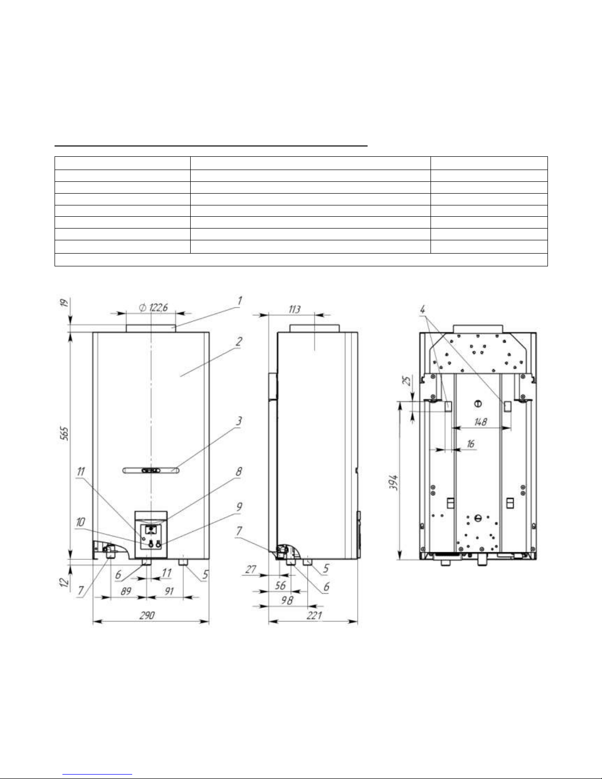
1 – gas removal device branch pipe; 2 - casing; 3 – viewing window;
4 – mounting holes; 5 - fitting of cold water supply, screw thread G 1/2;
6 - fitting of gas supply, screw thread G 1/2; 7 - fitting of hot water output, screw thread G 1/2;
8 - water temperature display; 9 – button of set temperature reduction;
10 - button of set temperature increase; 11 – power element discharge indicator.
Scheme 1. Overall and connection dimensions of the appliance
3. USAGE OF THE APPLIANCE
For normal and safe appliance operation the conditions presented in p. 2.2.9, 2.2.15 and 2.2.18 (see
Table 1, page 4) must be fulfilled. Non- compliance with these conditions can cause the appliance’s
inappropriate or unstable operation and even its breakdown. The heating effect of the appliance
indicated in the p. 2.2.2 is provided (with an accuracy ±5%) at rated gas pressure on the inlet into the
operating appliance, indicated in the Acceptance certificate.
3.1. Putting the appliance into operation
3.1.1. In order to put the appliance into operation in a general case it is necessary to:
a) Install the power element into the battery section (see p.3.4, page 8);
b) Open the stop valve of cold water by the inlet into the appliance;
c) Open the stop valve on the gas pipeline by the inlet into the appliance
d) Open the hot water tap, while spark discharges should appear between the plug and ignition burner (if
the water flow going through the appliance will be at least 2.5 l/min), from the spark discharges the
ignition burner should ignite and from the ignition burner the main burner should ignite. After igniting
the main burner the ignition burner’s flame must go out.
ATTENTION! To avoid burns, do not approach your eyes too close to the viewing window while the
appliance is being switched on.
Note: At first launching of the appliance or after long-term period of break in appliance’s operation, the
ignition burner’s ignition will occur only after air removal out of gas pipeline. As the spark discharges last
not more than 60 seconds after switching the water on, for continuing the ignition it s necessary to close the
hot water tap, and then open it again. You need to repeat this procedure until complete air removal out of the
pipeline and until the ignition burner ignites.
3.1.2. Changing of water consumption with which switching the appliance on and off occurs is effectuated
by the knob of the tap 15 (scheme. 14, 15, 16). Turning the knob 15 clockwise (counterclockwise)
leads also to reduction (increase) of consumption of water running through the water heater.
Switching the appliance on at leftmost position of the knob of the tap 15 (minimal water consumption –
see scheme 14, 15, 16) occurs at water consumption 2,5 l/min, switching off - at 2 l/min. Such knob position
is recommended at low inlet water pressure (with small consumption of water provided by the water supply
network).
Switching the appliance on at rightmost position of the knob of the tap 15 (maximal water
consumption) occurs at water consumption 3 l/min, switching off-at 2,5 l/min. With such knob position it is
possible to receive increased consumption of heated water by the appliance’s outlet..
3.2. Water temperature regulation
3.2.1 Water temperature regulation at the appliance’s operation.
Page 10

12
3.2.2. The temperature of hot water running out of the appliance is shown on the digital display 8 (see
scheme 1). Also on display, when pressing the buttons 9 or 10 the hot water temperature set by the
user is shown. Pressing the button 9 reduces the set temperature, pressing the button 10 increases it.
The hot water temperature can be set in the range from 35 °С to 70 °С: in the range from 35...50 °С
with a step of 1 °С, and in the range from 50…70 °С – with a step of 5 °С. In 2-3 seconds after you
stop pressing the control buttons the real temperature of hot water by the appliance’s outlet is shown
on display.
When water flow through the appliance is changed (by the water tap or due to change of pressure in the
water supply pipeline) and when gas pressure in the network or inlet water temperature is changed, the
control system automatically changes gas consumption, keeping the water temperature set by the user.
Note.. The possibility of keeping the set hot water temperature is limited by the appliance’s heating
effect (18 kW), i.e. in case of low inlet water temperature (in winter time), or in case of high set water
temperature and substantial increase of its consumption the hot water temperature by the appliance’s outlet
can be reduced to a value lower than the set one (error code Н1). So in order to keep the set hot water
temperature more stably it is recommended to set water temperature not more than 45 ...50 °С and limit the
water flow through the appliance, turning the knob 15 (scheme.) clockwise up to the stop (into the leftmost
position).
After switching the appliance on, setting new temperature or changing the water flow through the
appliance, the set water temperature will not be reached immediately, but only in some time, necessary for
automatic adjustment of the main burner’s power. At that, a short-term increase of water temperature by the
appliance’s outlet higher than the set one is possible..
When water consumption is reduced to 2...2,5 l/min and less automatic switching off of the appliance
will occur. In case of water consumption not much higher than the switching off threshold the appliance’s
operation may be unstable (error code L0).
The control system remembers the last set temperature value and at the appliance’s next launching it
will heat water to this temperature. The appliance’s memory is energy-dependent: when switching a new
appliance on or after the power elements replacement the system sets water heating temperature 45 °С by
default.
Note 1. Water overheating in the heat exchanger causes the appearance of noise during the appliance’s
operation and causes fast scale deposit appearance in the heat exchanger’s pipes and narrowing of their flow
sections, what in some time will lead to the appliance’s operation efficiency reduction and weakening of hot
water jet. So in order to reduce the appliance’s output water temperature it is not recommended to use a
mixing vessel, adding cold water but to use the above listed methods.
Note 2. It is not recommended to set high hot water temperature by the appliance’s outlet if not
necessary, as water overheating in the heat exchanger causes the appearance of noise during the appliance’s
operation and causes fast scale deposit appearance in the heat exchanger’s pipes and narrowing of their flow
sections, what in some time will lead to the appliance’s operation efficiency reduction and weakening of hot
water jet. So in order to reduce the appliance’s output water temperature it is not recommended to use a
mixing vessel, adding cold water but to set the temperature needed in the water pumping point by means of
control buttons.
3.3. Switching the appliance off
3.3.1 In order to switch the appliance off it is enough to stop water flow through it, closing all hot water
taps. After closing all hot water taps it is necessary to make sure that the main burner’s flame has
completely gone out.
ATTENTION! If after closing all hot water taps the main burner is still operating, it is necessary
to immediately block gas supply by means of the gas stop valve of the appliance’s inlet, and call a
specialized service organization for the appliance’s repair.
Page 11

13
3.3.2 When you finish using the appliance (at night time, not being at home etc.) it is necessary to switch
it off, following the following sequence:
a) Close the hot water taps;
b) Close the stop gas valve by the appliance’s inlet;
c) Close the cold water stop valve by the appliance’s inlet
In case of hard water, in order to reduce scale deposit appearance it is recommended to reduce water
consumption by the hot water tap before closing it until the main burner switches off (less than 2
l/min) and let the water run through the appliance until it is warm. Then close the hot water tap.
3.4. Replacing the appliance’s power elements
3.4.2. The indicator of the power element’s discharge is the flickering of the indicator 11 (see Scheme 1)
3.4.3. The new power element of typical size D is installed into the battery section 13 (see scheme. 10,
scheme11, scheme. 12).
When installing the power element it is necessary to observe polarity in accordance with the scheme on
the inner side of the section’s cover.
It is recommended to install alkaline power element type LR20 with high energy output ratio that
ensures more durable operation of the appliance. Installation of low-quality power elements or elements with
low energy output ratio may lead to their quick discharge and the appliance’s loss of function.
3.5. Protection from freezing
If after switching the appliance off water freezing in it is possible, it is necessary to drain the water out
of it as follows:
a) Close the gas stop valve and cold water tap by the appliance’s inlet;
b) Open the hot water tap and turn the knob of the tap 15 (scheme 10, scheme 11, scheme 12) to the
rightmost position;
c) Unscrew the gag 14 and let the water leak into a tank;
d) Screw the gag 14 back up to the stop and close the hot water tap.
3.6. Actions in emergency situations
In case of emergency situation during the appliance’s operation it is necessary to:
a) Close the gas stop valve by the appliance’s inlet;
b) Close the cold water stop valve by the appliance’s inlet (in case of water leakage);
c) Call a specialized service organization for the appliance’s repair.
ATTENTION! In case of failures in the combustion products removal system gas supply to the
burner stops. In case of the appliance’s switching off by a signal from the thermo relay (draught sensor
16, Scheme 10, Scheme 11, Scheme 12) it is necessary to close the hot water tap and ventilate the
premise.
Restarting of the appliance will be possible after the thermo relay cools down (in 1-2 minutes). In
case of the appliance’s repeated switching off by the draught sensor it is necessary to address to the
specialized service organization for gas removal system failure elimination. Disconnecting the draught
sensor or its incompetent handling is unacceptable and may lead to sweetdamp poisoning.
4. appliance treatment
In order to ensure long-term and failure-free operation of the appliance and keep its operating
characteristics it is necessary to regularly effectuate its examination, treatment and technical service.
Page 12

14
In order to ensure fire safety it is necessary to carefully and attentively look after the burners’ cleanliness,
not to allow smoky flame appearance at gas combustion, which leads to soot deposit appearance on the
heat exchanger. At that gaps between the heat exchanger’s fins are covered with soot and as a result the
flame casts out from the combustion chamber which can lead to fire.
The examination and treatment of the appliance are performed by its owner.
Technical service of the appliance is performed by the specialized service organization not later than 12
months from the date of installation and then not less than once per 12 months.
ATTENTION! Works connected with technical service are not the manufacturer company’s
warranty liabilities and are effectuated at the customer’s cost.
.
4.1 Examination
4.1.1. Every time before switching the appliance on it is necessary to:
a) Make sure that there are no flammable objects next to the appliance;
b) Make sure that there is no smell of gas in the premise, in case if the smell of gas is detected, address to
the gas facilities service.
4.1.2. At the ignition burner’s ignition it is necessary to check its operability by the combustion behavior:
the ignition burner’s flame must not be smoky and must reach the flame sensor’s electrode and the main
burner.
4.1.3 After the main burner’s ignition it is necessary to visually check its operation: the flame should be
blue and straight without any yellow smoky edges indicating the contamination of the inner channels of the
burner’s blades.
The burner blade’s inner channels contamination causes incomplete gas combustion and it leads to the
appearance of big amounts of the following:
- carbon monoxide, which can cause poising;
- soot that forms deposit on the heat exchanger what worsens heat exchange and can cause the
appliance’s breakdown
4.2 Treatment
4.2.1. The appliance should be kept clean, for this it is necessary to regularly remove dust from the upper
surface of the appliance, and also to wipe the casing at first with a wet rag, then with a dry one. In case of
substantial contamination, it is necessary to wipe the casing at first with a wet rag moistened in a neutral
detergent, then with a dry rag.
4.2.2. It is forbidden to use detergents of heightened effect and containing abrasive particles, gasoline or
any other organic solvents to clean the surface of the casing and plastic parts.
ATTENTION! It is allowed to perform all appliance treatment operations only after the appliance
is switched off and cooled down.
5. RULES OF TRANSPORTATION AND STORAGE
The appliance must be kept and transported in the package only in the position indicated on the handling
marks.
The appliance must be kept in a closed premise which guarantees protection against atmospheric and other
harmful impacts at the air temperature from -50 С to +40 С and relative humidity not more than 98%.
In case of the appliance’s storage for more than 12 months it must be subject to conservation in
accordance with GOST 9.014 – 78 standard.
Apertures of the inlet and output fittings should be closed by the gauges or cover plugs.
Every 6 months of storage the appliance must go under technical examination, during which the absence
of wet entry and dust contamination of unit and details of the appliance are checked.
Page 13

15
The appliances should be put in not more than 8 tiers during collection into stacks and transportation.
6. safety measures
6.1. Mounting of the appliance, putting it into operation and its technical service must be performed only
by a specialized service organization. The appliance’s mounting must be effectuated in accordance with the
project corresponding to the requirements of the Federal and local regulatory acts, governing the installation
of the gas-powered equipment.
6.2. Placing the appliance, pipelines, exhaust flues, smoke exhausters and other engineering equipment
should provide safety of their operation, ease of technical service and repair.
6.3. Before connecting the appliance it is necessary to do the following:
-Check the compliance of the settings indicated in the Acceptance certificate and in the table on the
appliance with the type and pressure of gas available at the place of the appliance’s installation. In case of
non-compliance it is necessary to effectuate the appliance’s rendering to the used type and pressure of gas in
accordance with p.7.10 (page 15)
-To make sure that the exhaust flue is correctly mounted and air-tight;
- In order to provide the appliance’s correct operation and keep the warranty, it is necessary to follow the
requirements of this manual.
7 APPLIANCE INSTALLATION
The appliance must be installed by the specialized service organization. After the appliance’s installation,
checking its working capacity and the appliance’s owner’s instructing by an employee of the organization
that installed the appliance, a mark about the appliance’s installation should be made in the Certificate of
installation, technical service and repair and in the warranty coupons
7.1 Place and scheme of installation
7.1.1. The appliance must be installed in kitchens or any other heated non-residential premises according
to the project of gasification and set of rules SP 62.13330.2011.
7.1.2. The volume of the premise where the appliance is installed should be not less than 8 m3.
7.1.3. The premise where the water heater shall be installed must have good ventilation and constant fresh
air inflow (window or opening transom), because while the appliance is on, oxygen combustion occurs. Grids
or gap in the bottom part of the door or wall must not be tightly closed
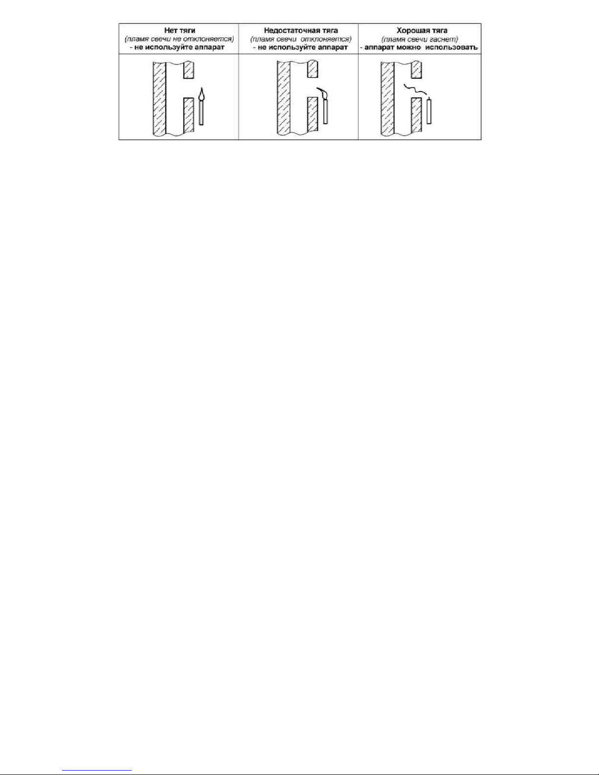
7.1.4. The appliance must be connected to the exhaust flue with a good draught (rarefaction 1, 96…29, 4
Pа) and besides it should be located as close to the exhaust flue as possible. One of the available ways to test
the draught in the exhaust flue is presented on the scheme 4.
No draught (the candle flame Insufficient draught Good draught
doesn’t’ bend) –
do not use the (the candle flame bends)
(the candle flame goes out)
appliance do not use the appliance -the appliance can be used
Page 14
16
Scheme 4. Way of testing draught in the exhaust flue
Page 15
17
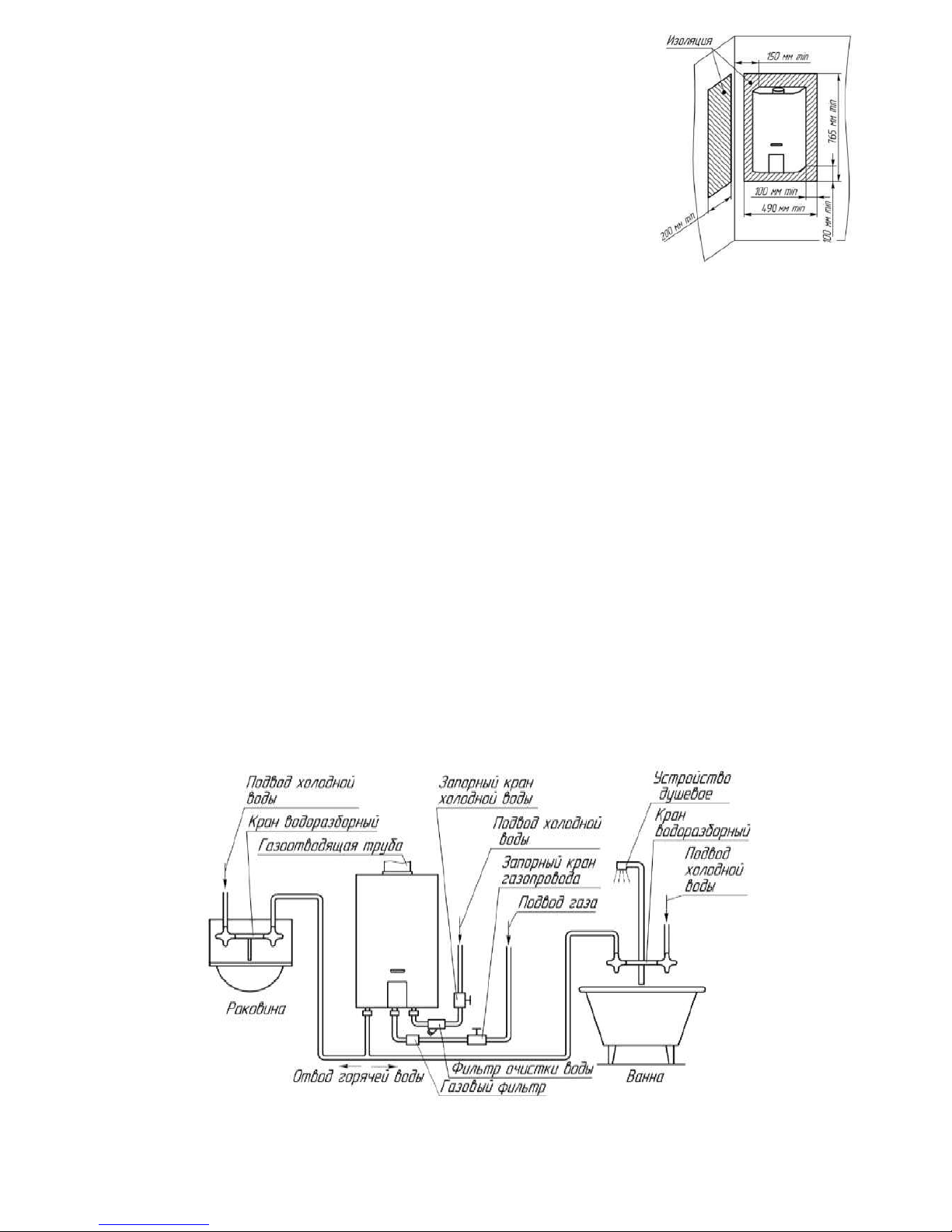
7.1.5 The appliance must be installed on the fire resistant walls:
brick, concrete (with a ceramic plating or without it).).
It is acceptable to install the appliance on firehard walls if the wall is insulated
with a zinc-coated steel sheet with thickness 0, 8…1 mm along the basalt felt
woolen board with thickness 3…5 mm. Insulation of the wall should go over
the overall dimensions of the appliance’s body frame for at least 100 mm from
each side (see scheme 5).
The distance from the appliance’s lateral surfaces to firehard walls without
insulation should be at least 250 mm. If the indicated distance is reduced to 150
mm, it is necessary to install the heat insulation (upholstery of walls by the
zinc-coated steel sheet on the sheet of the heat insulation material).
When installing the appliance on fire resistance walls it is not needed to install
the insulation.
7.1.6 It is forbidden to install the appliance on wooden walls; plastered walls which have wooden base;
on walls covered with highly flammable materials.
7.1.7 It is forbidden to install the appliance above a source of heat or open flame.
7.1.8. Place and height of the appliance’s installation should meet the requirements of p .7.7 (page 14) of
this manual. Besides it is recommended to install the appliance on the height so that the viewing window will
be on the level of consumer’s eyes or as close to this level as possible.
Also for effectuating the technical service at the appliance’s installation it is necessary to keep the
following spaces:
- The distance from the appliance’s lateral surface to the lateral wall must be not less than 150 mm;
- Free space in front of the appliance’s front surface should be not less than 600 mm.
7.1.9. Scheme of appliance’s installation (connection) is represented on the scheme 6. It is recommended to
connect the appliance at first to the water supply system, to fill it with water and then connect it to the gas
network.
Technical staff manual
Scheme 5. Appliance
installation on firehard walls
Scheme 6. Scheme of appliance’s installation
Page 16

18
7.2 Mounting the appliance
7.2.1 Before installing the appliance it is recommended to remove the casing, for this it is necessary
to do the following:
a) Unscrew in the appliance’s bottom part two self-threading screw fixing the casing to the carrier on
the body frame;
b) Disconnect the cable, connecting the display PCB with the electronic control board
c) Pull the casing’s bottom part towards yourself, move it upwards and remove from the appliance.
8 If the casing or the appliance’s body frame is covered with a protective polyethylene film, it is necessary
to remove it before installation. Also it is necessary to remove the stickers with warning notes and
advertising information from the front surface of the casing (if there are any)
7.2.2. The appliance is hanged by the mounting apertures (on the back wall) on two hooks, mounted on
the wall (hooks and dowels are included into the supply package). Position and sizes of the mounting
apertures are shown on Scheme 1, Scheme 2 (page 6). If a harness board is included into the supply
package, it is recommended to use it for marking the holes on the wall.
7.2.3 Overall and connecting dimensions for connecting water pipes, gas pipes, and pipes for removal
combustion products are presented on the scheme 1 and 2 (page 6).
Page 17

Technical staff manual
19
7.3. Connecting the appliance to the water supply system
7.3.1. In order to increase the appliance’s working lifespan and improve its exploitation characteristics is
recommended to install a water filter by the appliance’s inlet (see scheme 6)
7.3.2. In order to facilitate further technical service it is necessary to install by the appliance’s inlet a stop
valve on the cold water supply pipeline. The stop valve must be easily accessible.
7.3.3. Connecting appliance to the water supply system should be effectuated with metallic tubes or
flexible hoses with inner diameter not less than 13 mm. The length of the flexible hose for water inlet or
output should be not more than 2,5 m. Rules of flexible hoses installation are represented in the p. 7.6, page
13.
7.3.4. Cold water connection must be effectuated to the fitting of cold water supply 5, and hot water
connection - to the fitting of hot water outlet 7 (see scheme 1, 2), having previously removed protective gags
from the fittings.
7.3.5. Connection of pipes of hot and cold water should not be accompanied by mutual interference of
pipes and parts of the appliance in order to avoid displacement or breakage of separate details and parts of the
appliance and disturbance of water system’s air-tightness.
7.3.6. Before connecting the appliance to the water supply network it is necessary to open the cold water
supply for some time to clean the pipe of water supply to the appliance and prevent unwanted entering of the
contamination and sediments at its first starting up.
7.3.7. After connecting the pipelines to the appliance it is necessary to test joints on air-tightness. Airtightness check is done as follows:
a) Open the hot water tap;
b) Open the cold water stop valve by the appliance’s inlet;
c) After filling the appliance’s duct with water, close the hot water tap and examine the joints.
Leakage in the joints is unacceptable. It is also recommended to examine the joints of the appliance’s
water duct, as their air-tightness disturbance is possible in case of the appliance’s transportation and
storage conditions violation. Tighten the joints if necessary.
7.4 Connecting the appliance to the gas system
7.4.1. In order to increase the appliance’s working lifespan and improve its exploitation characteristics is
recommended to install a gas filter by the appliance’s inlet (see scheme 6, page 11)
7.4.2 In order to ensure stable operation of the appliance it is necessary to effectuate the gas line connection
with metal pipes or flexible hose with an internal diameter not less than 13 mm. The flexible hose for
supplying gas, in accordance with the SNiP 42-01-2002 requirements must be resistant to the supplied gas at
set temperature and pressure. Flexible hose length should not be more than 2.5 meter. Flexible hoses
installation rules are given in p. 7.6. Pipes or a flexible hose should be connected to the fitting 6 (see scheme.
1,2, page 6) after removing the protective gag from it.
7.4.3. Installation of the gas pipelines’ dismountable joints should be kept to a minimum.
7.4.4. When connecting a gas line to the appliance, there should be obligatory a stop valve installed by the
appliance’s inlet. The stop valve must be easily accessible.
7.4.5. Connecting the gas pipe must not be accompanied by mutual interference of pipes and parts of the
appliance in order to avoid displacement or breakage of individual details and parts of the appliance and a
violation of the gas line air-tightness.
7.4.6. After connecting the appliance to the gas line, the joints of connection of the appliance with the pipes
should be tested on air-tightness. Air-tightness check in the joints of gas supply is made on non-operating
appliance and when the appliance’s inlet stop valve is open. Gas leakage is not allowed.
Page 18
Technical staff manual
20
Checking the air-tightness of the gas joints is effectuated by means of soap solution bubble test of the
connection points (or other safe methods without using open flame). Appearance of bubbles indicates gas
leakage.
.
7.5 Connecting the appliance to the LPG cylinder
7.5.1. Before connecting the appliance to LPG cylinder make sure that your appliance is adjusted to work
with this type of gas. Otherwise it is necessary to render it (see p. 7.10, page 15).
7.5.2. The LPG cylinder must necessarily be equipped with a reduction unit with vapor phase stabilization
pressure 300 mm w.g., and the vapor phase output at least 1 m3/h.
ATTENTION!
Usage of reduction units with stabilization pressure different from 2.9 kPa is PROHIBITED.
7.5.3. The length of a flexible hose for connecting the appliance should be not more than 2.5 m and the
inner diameter not less than 12 mm. A flexible hose for gas supply should be resistant to the supplied gas at
set temperature and pressure. Rules of flexible hoses installation are given in p. 7.6.
7.5.4 The flexible hose must be connected to the fitting 6 (see scheme 1, 2 page 6), after removing the
protective gag from it.
7.5.5. A gas stop valve should be installed by the appliance’s inlet. The stop valve must be easily
accessible. It is also recommended to install a gas filter by the appliance’s inlet
7.5.6. After the mounting termination, it is necessary to check the joints and the entire length of the
connecting hose for air-tightness (see p.7.4.6).
7.5.7. In order to avoid accidents it is PROHIBITED TO:
- store gas cylinders and lay hoses under direct sunlight, next to heat sources (ovens, stoves, radiators and
other heating appliances);
- heat the gas cylinders with flame or heating appliances;
- use damaged gas cylinders.
7.5.8. It is recommended to store gas cylinders in a special metal cabinet to restrict access of children or
other unauthorized persons.
7.6. Rules of flexible hoses installation
7.6.1 Flexible hoses applied for the appliance’s connection, should be certified for
the appropriate use.
Upon their working lifespan termination they should be obligatory replaced..
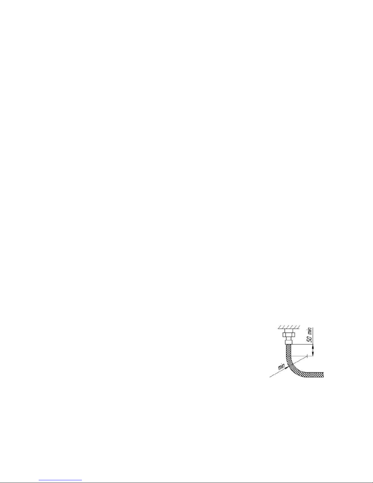
7.6.2. If the appliance is connected by means of the flexible hoses, it is necessary to
take into account the following rules of mounting:
- do not twist the hose relative to the longitudinal axis;
- prevent the hose from bending close to the tips: the length of hose’s area next to the scaling-off, which
shouldn’t be subject to bending shall be not less than 50 mm;
- The hose’s bending radius, as measured by the external forming shall be not less than 90 mm.
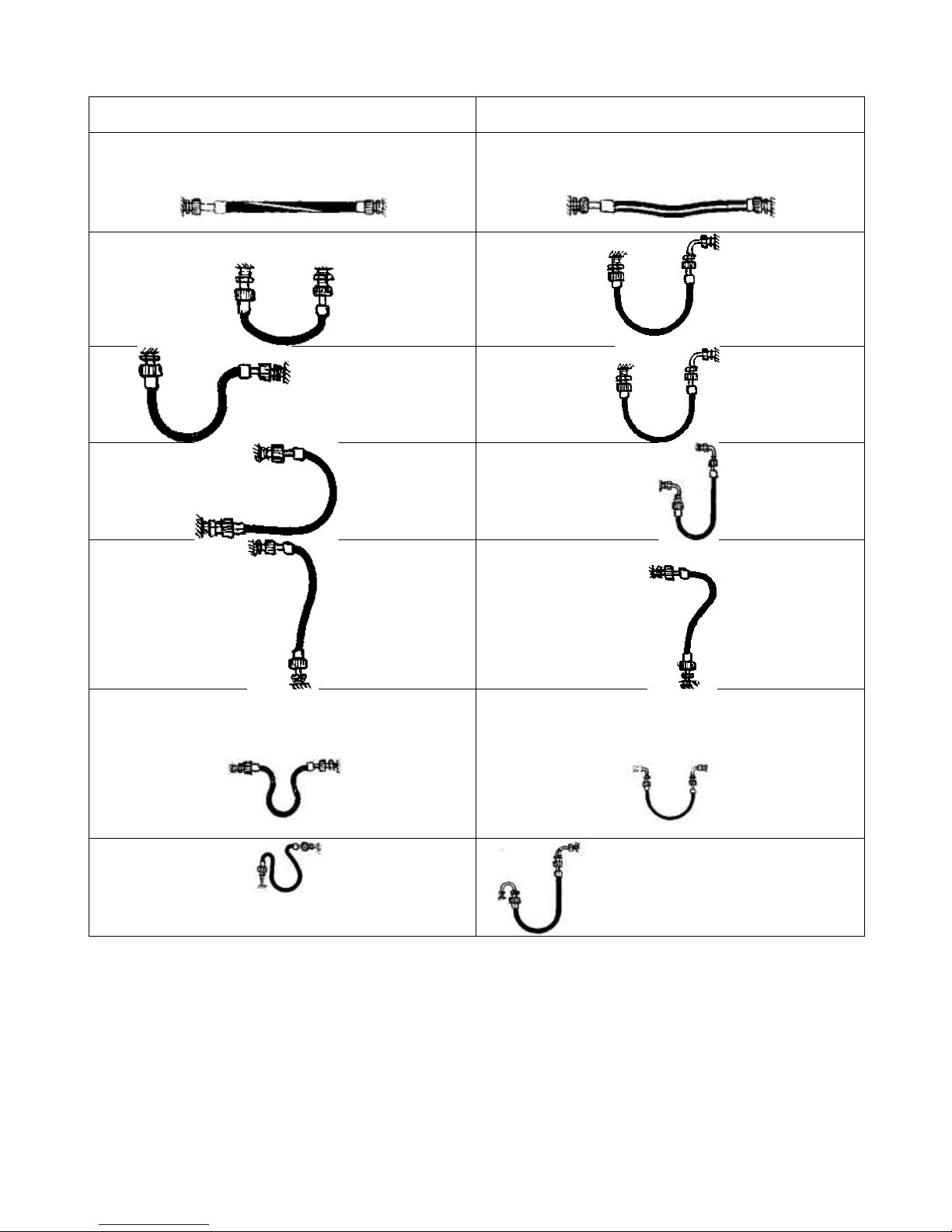
It is recommended to:
- use angle connections and adapters to avoid hoses fractures next to the tips
- use interval supports when long hoses are mounted;
- At rectilinear arrangement mount the hoses with sagging.
Page 19
Technical staff manual
21
Recommended mounting schemes of the flexible hoses are presented in the table 5.
Table 5. Flexible hoses installation scheme
7.6.3. Mounting a hose is necessary to begin with the non-movable elements of the hose which have a
pipe cylindrical thread (if a counterpart is stationary).
7.6.4. Sealing of the fitting’s threaded joint with a counterpart (radial connection) must be made using a
Teflon tape sealing material (FCM) or sealant that provides air-tightness of the threaded joint.
7.6.5. The threaded joint of the captive nut (end connection), for the movable and also non-movable parts
with a counterpart fitting must be performed applying gaskets. Gasket material- oil and petrol resistant
rubber or polytetrafluorethylene.
.
Wrong
Correct
Page 20

7.7.Connecting the appliance to the exhaust flue
7.7.1. In order to remove all gas combustion products and to ensure safe operation of the appliance the
following requirements to the exhaust flue and flue pipe, connecting the exhaust flue with the appliance
should be fulfilled:
- the exhaust flue should be air-tight and resistant to the heating load and impact of combustion products
It is not allowed to use ventilation channels to remove the combustion products;
- Draught in the exhaust flue should vary from 1,96 up to 29,40 Pа (see table 1 page 4);
- Flue pipe’s material should be corrosion- resistant, nonflammable and sustain durable operation at the
temperature up to 200 С. The recommended materials are: stainless steel, zinc-plated and enameled steel,
aluminum, copper with wall thickness at least 0,5 mm;
- The flue pipe must have an inner diameter not less than 110 mm;
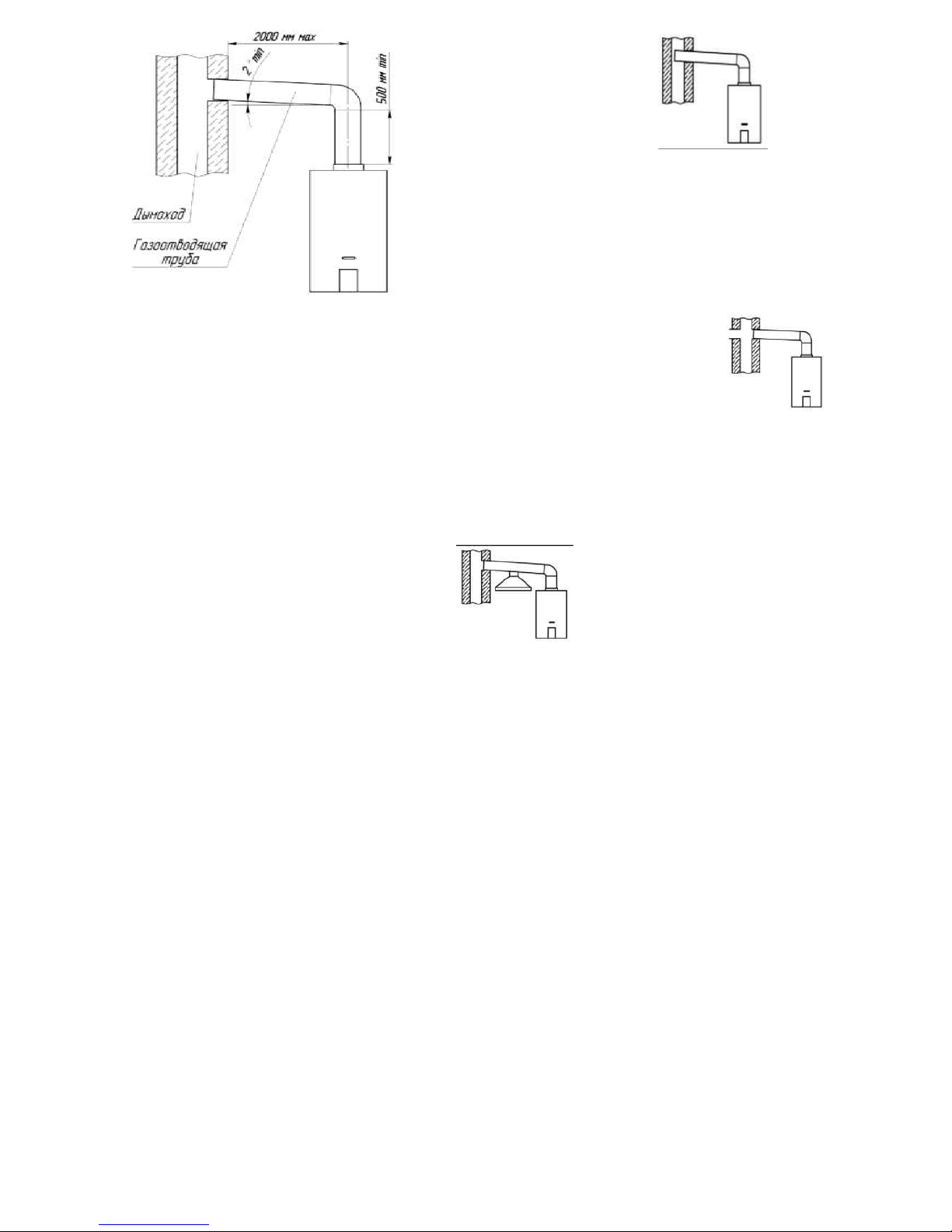
-Length of the vertical part of the flue pipe from the appliance must be at least 500 mm;
-Length of the flue pipe from the vertical part to the exhaust flue must be not more than 2 m;
- The flue pipe should have a slope of not less than 2 up in the direction of the link-up point with the
exhaust flue and minimal number of turns (not more than three)
- - The flue pipe and its connection with the appliance must be air-tight; connecting the pipe with the
appliance should be performed in accordance with the scheme 7.
Page 21
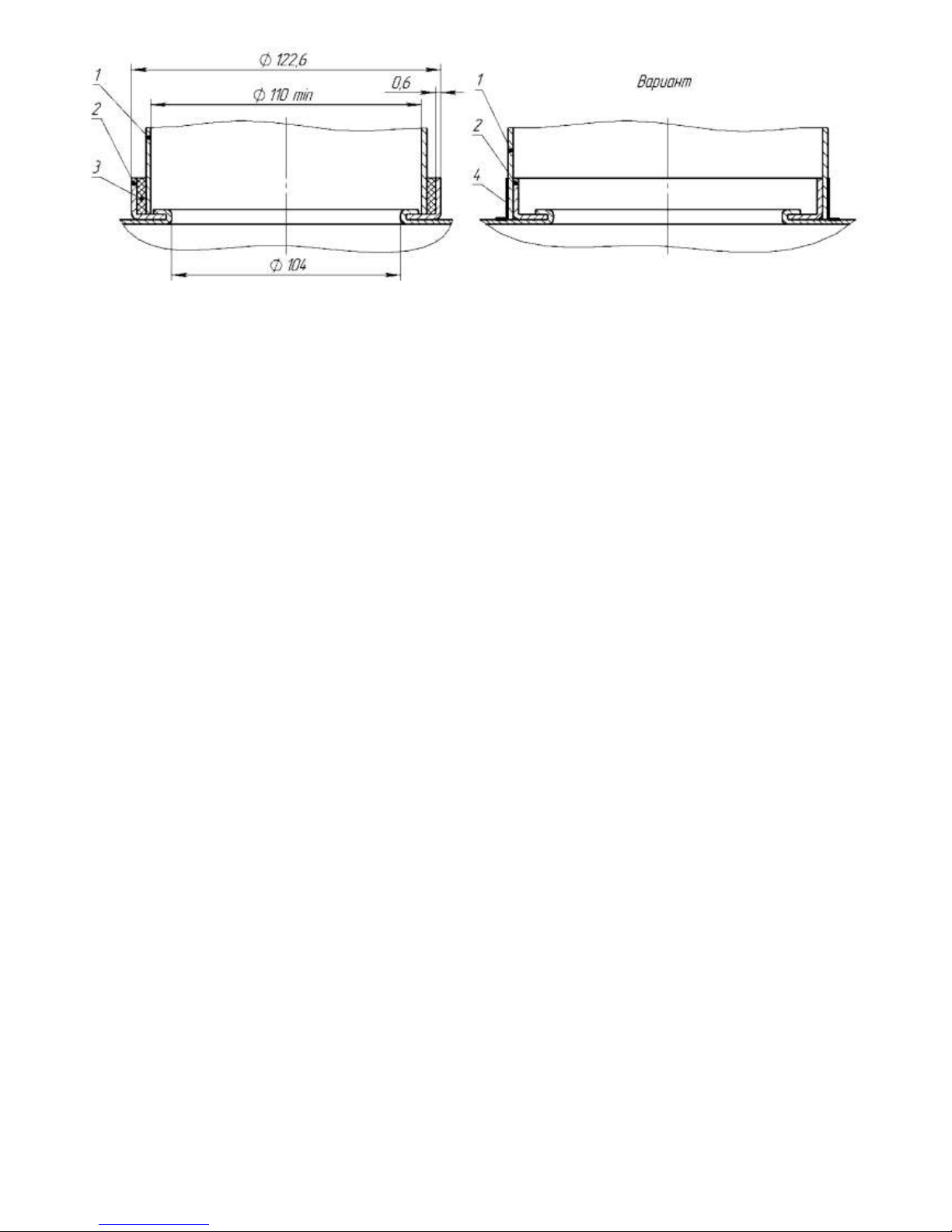
Scheme 7. Scheme of connecting the flue pipe to the appliance
7.7.2. Variant of connecting appliance to the exhaust flue is represented on the scheme 8.
1 – flue pipe; 2 – appliance’s gas removal device hose;
3 - heat-resistant sealant; 4- aluminum heat-resistant tape
Page 22
The end of
the flue pipe is too close to
the opposite side of the
exhaust flue.
There is an aperture on the
level of flue
pipe connection (including
another device connected to
it).
Two devices have one
connection to the exhaust flue
.
Scheme 8. Connecting the appliance to the exhaust
flue
1
Correct Wrong
Page 23
15
7.8 Installation of the appliance’s power elements
Power elements of the typical size D are installed into the battery section 13 (see. Scheme 10, Scheme 11,
Scheme 12) in accordance with polarity indicated on the inner side of the cover of the section. It is
recommended to install the alkaline power elements of the LR20 type, with higher energy output ratio
providing more durable operation of the appliance.
7.9 Checking the appliance
After installing the appliance and checking it on air-tightness, you must check: the operation of the
ignition and main burner (p. 4.1.2, 4.1.3, page 9), automatic safety devices operation (п. 8.2.6, page 20), and
the hot water’s temperature and consumption. Switching the appliance on and off and regulation of its water
temperature must be effectuated in accordance with section 3 (page 7).
Note: After keeping the appliance in a premise with sub-zero temperature, it is recommended to perform
its first launching not earlier than in 1,5 h after it was brought to a warm premise.
If necessary (in case of insufficient water heating) the appliance’s inlet gas pressure should be checked.
In order to measure gas pressure, having previously closed the gas stop valve by the appliance’s inlet, it is
necessary to connect a manometer to the fitting 17 (Scheme 10, Scheme 11);
Gas pressure measurement must be effectuated on the operating appliance and at maximum gas
consumption. Gas pressure must comply with the value indicated in the Acceptance certificate.
7.10Rendering the appliance to another type and pressure of gas
7.10.1 Rendering the appliance to another type of pressure or gas must be done by a specialized service
organization. For rendering it is necessary to use only a branded set of details.
Before rendering it is necessary to switch the appliance off and close the gas stop valve.
7.10.2 In order to render the appliance to another type of gas or pressure it is necessary to replace the nozzles
of the main burner’s manifold and the nozzle of the
ignition burner for the nozzles with an orifice diameter in
accordance with table 1 for the type and pressure of gas
the appliance will operate on.
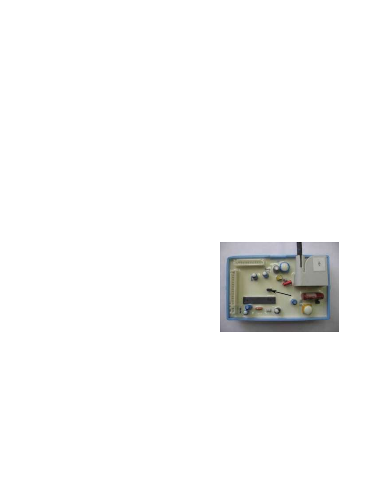
For operating on natural gas a jumper in the electronic
control block must be installed, it is shown with the arrow on
Scheme 13.
When rendering the appliance from natural gas to liquefied
gas it is necessary to remove the jumper from the electronic
control block (it is acceptable to install the jumper on one of the
contacts).
After rendering it is necessary to check the joints’ air-tightness.
The type and pressure of gas the appliance has been rendered on, must be indicate in the
Acceptance certificate (indicating the organization that effectuated the rendering and the date of
effectuation) and in the table on the appliance
.
Scheme9.Place of installation of a jumper in the electronic control block
8. Construction and operation control of the appliance
Page 24

16
8.1 Construction of the appliance
8.1.1 The wall-mounted appliance (see Scheme 1, Scheme 2 page.6) has a rectangular form formed by a
detachable casing 2.
8.1.2 The appliance «BaltGaz NEVALUX-6011» (Scheme 1) has the following elements on its front side of
the casing: viewing window 3 for watching the ignition and main burner flames; water temperature
display 8, buttons of setting water temperature 9 and 10, battery discharge indicator 11. All main
elements of the appliance are mounted on its body frame 19 (see Scheme 10, 11).
8.1.3 Function of the main units and components of appliance (see Scheme 10, 11, 12):
- Gas removal device 1 is designed to remove the combustion products to the exhaust flue;
- heat exchanger 2 provides transfer of the heat received at gas combustion to the water flowing through
its pipes;
- Gas and water unit 12 is designed to control gas supply to the ignition and main burners, and consists
of water and gas units and the valve block(the unit’s construction ensures gas supply to the ignition and
main burner only if there is water flow);
Page 25

17
Technical staff manual
- Ignition burner 3 is designed for igniting the main burner;
- Main burner 10 is designed for creating and burning air-gas mixture;
- Electronic control block 11 provides ignition control and gas supply to the ignition and main
burners;
- water temperature sensor 4 (Scheme 10, 11) is designed to measure the appliance’s output water
temperature;
- flame sensor 8 ensures control of the ignition and main burners’ operation;
- plug 9 is designed to create a spark charge for the ignition burner’s ignition;
- Gag 14 is used for draining the water from the water heater’s water circuit in order to prevent it from
freezing; a safety valve integrated into the gag is designed to protect the appliance’s water circuit from
high water pressure.;
- thermo relay 16 (draught sensor) is designed to switch the appliance off in case of no draught in
the exhaust flue
Page 26
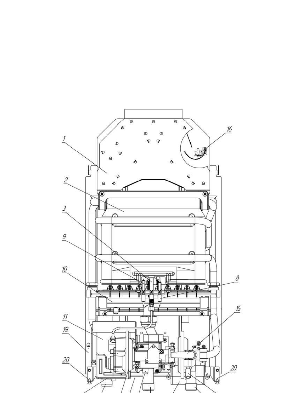
18
1 – gas removal device; 2 – heat exchanger; 3 – ignition burner; 4 – water temperature sensor;
5 - cold water supply fitting; 6 - gas supply fitting; 7 - hot water output fitting;
8 – flame sensor; 9 - plug; 10 – main burner; 11 – electronic control block; 12 – water and gas unit; 13 –
battery section; 14 – water drain plug; 15 – water consumption tap (located under the casing);
16 – thermo relay (draught sensor); 17 - gas inlet pressure measuring fitting; 18 - table; 19 – body frame;
20 – casing fixation screws.
Scheme 11. Appearance of the appliance «BaltGaz NEVALUX-6011» without casing
Page 27
Technical staff manual
19
8.2 Operation of the appliance
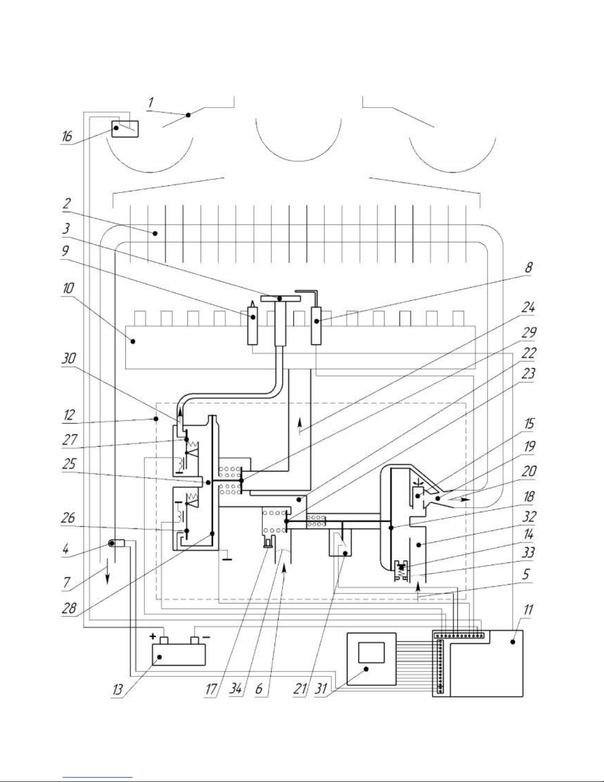
8.2.1 The appliance’s flow chart is represented on scheme 13
Page 28
User’s and technical staff manual
20
1 – gas removal device; 2 – heat exchanger; 3 – ignition burner; 4 – water temperature sensor; 5 – cold water
supply; 6 – gas supply; 7 – hot water outlet; 8 – flame sensor; 9 - plug; 10 – mail burner; 11 – electronic
control block; 12 – water and gas unit; 13 – battery section; 14 – water drain plug; 15 – water consumption
tap; 16 – thermo relay(draught sensor); 17 – gas inlet pressure measuring fitting; 18 – water unit membrane;
19 – Venturi fitting; 20 – cold water outlet to the heat exchanger; 21 –micro switch (water flow sensor); 22 –
gas unit; 23 – gas valve, controlled by the water unit; 24 – gas outlet to the main burner;
25 – valve block; 26 – electromagnetic servovalve (normally open); 27 – electromagnetic valve of the ignition
burner (normally closed); 28 – valve block membrane; 29 – two-step gas valve of the main burner; 30 –gas
outlet to the ignition burner; 31 – water temperature display PCB; 32 – water unit; 33 – water filter; 34 – gas
filter.
Scheme 13. Flow chart of the appliance «BaltGaz NEVALUX-6011»
8.2.2 At the beginning of water flow through the water block 32 with water consumption not less than 2,5…3
l/min the gas valve 23 is opened by the membrane stem 18 and the contacts of the micro switch 21 close. After
this the valve 27 opens gas supply from the cavity behind the membrane of the valve block 25 to the ignition
burner 3 and from the control block 11 high-voltage current impulses are supplied to the plug 9.From the
electric sparks between the plug’s electrode and the ignition burner’s nozzle the ignition of the ignition burner
occurs. After the ignition burner’s ignition, what can be defined by the flame sensor 8, the valve 26 closes gas
supply to the cavity behind the membrane of the valve block, gas from the cavity behind the membrane comes
out through the ignition burner and the membrane 28 of the valve block opens the valve 29 supplying gas to
the main burner 10 with the help of pressure drop. The main burner ignites and the ignition burner’s flame
goes out. The main burner’s operation is controlled by the flame sensor 8.
8.2.3 Then the electronic control block 11 compares the given water temperature value with the value
measured by the sensor 4.If the temperature difference exceeds 1oC, the electronic control block, controlling
the valves 26 and 27, corrects the position of the valve 29 changing this way the amount of gas supplied to the
main burner. Opening the valve 26 if the valve 27 is closed increases gas pressure in the cavity behind the
membrane 28, at that gas consumption reduces and the appliance’s power decreases. Opening the valve 27
when the valve 26 is closed reduces the pressure in the cavity behind the membrane 28, at that gas
consumption increases and the appliance’s power grows.
8.2.4 The tap 15 changes water consumption in a small range and the displacement of the membrane 18:
turning the tap clockwise reduces water consumption and increases the membrane’s displacement, turning the
tap counterclockwise increases water consumption and reduces the membrane’s displacement. So the tap 15
influences also the water consumption value, with which the appliance switches on (ignition of the ignition
burner, and then of the main burner) and switches off (switching off of the main burner). When the tap is
turned clockwise up to the stop (this position is shown on Scheme 14, 15), the water heater is switched on
with the consumption of 2,5 l/min, and switched off with the consumption of 2 l/min. When the tap is turned
counterclockwise up to the stop the water heater is switched on with the consumption of 3 l/min, and switched
off with the consumption of 2,5 l/min.
8.4.5.At water flow stop or at its consumption reduction to a volume less than 2...2,5 l/min the contacts of the
micro switch 21 open and the valves 23 and 29 close and the main burner’s flame goes out.
8.4.6. The appliance is equipped with safety devices, providing:
- Gas access to the ignition and main burners only in case if there is water flow
- Gas access to the main burner during the ignition only in case if there is a flame on the ignition
burner
water flow stop;
Page 29
User’s and technical staff manual
21
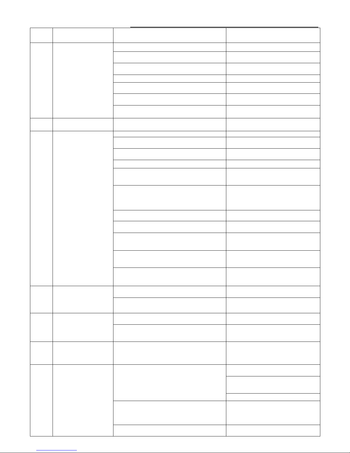
9 POSSIBLE FAILURES AND METHODS OF THEIR ELIMINATION
Table 6. Possible failures of the appliance «BaltGaz NEVALUX-6011»
Error
Failure
Probable reason
Methods of elimination
Insufficient water consumption (less than 2,5 l/min)
Increase water consumption.
No spark discharge
between the plug and
ignition burner before the
beginning of water flow
through the appliance
, the temperature indicator
is not glowing
There is no power element or it is discharged.
Incorrect power element installation.
Install an operative power element
correctly
The contacts or the connection circuit are
disrupted.
Check the connections and if necessary
clean up the contacts.*
Water flow sensor is out of order.
Replace the water flow sensor.*
Water unit is out of order (the membrane is
Repair or replace the water unit.*
The electronic control block is out of order.
Replace the electronic control block.*
Appearance of soot deposit on the plug’s electrode.
Effectuate cleaning of the plug’s electrode
from soot deposit.*
Е0
The appliance switches
off.
Gas supply stop.
Address to the responsible gas facilities
service.
Presence of air in the gas pipelines.
See p. 3.1.
The stop valve on the gas line by the inlet into the
appliance is closed or insufficiently opened.
Open the stop valve on the gas pipeline
Absence or low pressure of gas in the duct.
Address to the responsible gas facilities
service.
The LPG reserve in the cylinder has expired
Replace the LPG cylinder .
The connection of the electronic control block to
the flame sensor, the electromagnetic valve of the
Check the connections, if necessary, clean
up the contacts or replace the cables.*
Е1
In 60 s after the spark
discharges begin the
electronic control block
does not detect the signal
from the flame sensor
The flame sensor is out of the zone of the ignition
burner’s flame or its electrode touches the details
of the ignition or main burner.
Adjust the flame sensor’s position (its
electrode must be in the zone of the
ignition and main burners’ flame and must
not touch the burners’ details).*
Contamination of the nozzle or air inlet duct of the
Clean the ignition burner.*
The electromagnetic valve of the ignition burner is
out of order.
Replace the valve (or the valve block).*
The gap between the ignition plug and the nozzle
of the ignition burner is disrupted.
Install a gap of 4…5 mm between the
plug’s electrode and the ignition burner’s
nozzle.*
The high-voltage cable is put onto the ignition plug
not up to the stop (the spark goes to the burner’s
Put the high-voltage cable onto the
ignition plug up to the stop.*
Appearance of soot deposit on the plug’s electrode
or on the flame sensor’s electrode
Effectuate the cleaning of the plug’s or the
flame sensor’s electrode from soot
deposit.*
Actuation of
electromagnetic valves
occurs before the
appearance of signal from
The electromagnetic valves are out of order.
Replace the electromagnetic valve (or
valve block) that is out of order).*
Е3
The electronic control block is out of order .
Replace the electronic control block.*
The flame sensor transmits
a signal about flame
presence before the
appearance of signal from
An attempt to ignite the appliance from an
extraneous flame source.
Effectuate the appliance’s ignition in
accordance with section 3.
Е4
The electronic control block is out of order.
Replace the electronic control block.*
Е5
The electronic control
block does not receive a
signal from the hot water
The connection between the electronic control
block and the water temperature sensor is
disrupted.
Check the connection, replace the water
temperature sensor if necessary .*
Failed seven-times attempt
to ignition (the ignition
burner ignites, than the
main burner ignites and
then in some seconds the
main burner’s flame goes
out and the ignition
process repeats)
Open the gas stop valve by the inlet into
the appliance completely.
Low gas pressure
Address to the responsible gas facilities
service.( or replace the LPG cylinder ).
Е7
Clean the gas filters.*
The flame sensor is not in the zone of the main
burner’s flame.
Adjust the flame sensor’s position (its
electrode must be in the zone of the
ignition and main burner flames).*
The electromagnetic valves are out of order
Clean or replace the electromagnetic
valves.*
Page 30

User’s and technical staff manual
22
Error
code
Failure
Probable reason
Methods of elimination
Jamming of the water or gas unit stem (water flow
sensor is constantly closed).
Repair or replace the unit that is out of
order.*
Appearance of soot deposit on the flame sensor’s
electrode.
Effectuate the flame sensor’s electrode’s
cleaning from soot deposit.*
Е8
Switching the appliance
off by the draught sensor
The error code appears on
display in 2-5 minutes
after the appliance was
switched off if the water
tap is not closed.
No draught in the flue pipe.
Clean the flue pipe.*
Draught sensor failure or disruption of its
connection.
Check the joints and clean up the
contacts or replace the details that are out
of order if necessary.*
99
The number 99 is
flickering for some time,
then the code LO is
shown on display and the
appliance switches off.
After this repeats seven
times the error code Е7
Short circuit in the circuit of the water
temperature sensor or inside of the connector’s
terminal strip.
Remove the short circuit or replace the
sensor together with the connection
cables.*
LO
Insufficient gas
consumption for the main
burner’s normal
operation.
Small water consumption (less than3,5 l/min).
Increase water flow through the appliance.
Clean the heat exchanger’s pipes and the
hot water pipe* from scale deposit or
address to the community facilities in
order to eliminate the cause of low water
Set hot water temperature is not much higher than
the cold water temperature by the inlet into the
Set a higher hot water temperature.
Н1
The appliance doesn’t
heat water to the set
temperature
High hot water temperature is set at big water
consumption.
Set a lower temperature of hot water or
reduce water flow through the appliance
(see p.3.2).
Low gas pressure.
Open the gas stop valve by the inlet into
the appliance completely.
Address to the responsible gas facilities
service ((or replace the LPG cylinder ).
Clean the gas filters.*
Dust deposit in the main burner’s channels (the
main burner’s flame is weak, stretched out, with с
yellow smoky tongues).
Clean the main burner.*
Soot deposit on the heat exchanger’s fins or scale
deposit in the heat exchanger’s pipes.
Clean the heat exchanger from soot and
its pipes and the hot water pipe from
scale deposit.*
Water and gas unit or the electronic control block
is out of order
Repair or replace the water and gas unit
or the electronic control block
-
The main burner ignites
with a “clap” and the
flame casts out of the
casing’s viewing window.
The ignition burner’s flame is small or bends
aside and does not reach the main burner (the
nozzle is contaminated or the air inlet duct to the
ignition burner is contaminated with dust, low gas
pressure).
Clean and install the ignition burner
correctly.*
-
Small water consumption
by the appliance’s outlet
at normal water flow in
the pipeline.
Scale deposit in the heat exchanger’s pipes or in
the hot water outlet pipe.
Clean the heat exchanger’s pipes and the
hot water pipe from scale deposit.*
Water filters are contaminated.
Effectuate water filters cleaning.*
-
Unstable operation of the
appliance: sustainable hot
water temperature
fluctuations are detectedн
Small water consumption is set.
Increase water consumption.
Water pressure in the water supply network is less
than 30 kPa (water consumption is less than 3,5
Address to the community facilities in
order to eliminate the cause of low water
The appliance’s connection to the water supply
network was effectuated violating the
Effectuate the appliance’s connection to
the water supply network in accordance
-
The main burner’s flame
doesn’t go out when the
hot water tap is closed.
Water or gas unit stem jamming.
Close the gas stop valve by the inlet into
the appliance and call a specialized
service organization.
Page 31

User’s and technical staff manual
23
* - The works are effectuated by a specialized service organization..
10. GENERAL INSTRUCTIONS
10.1. Mounting of gas appliances for domestic use must be effectuated in accordance with the project for
appliance’s installation and the set of rules SP 62.13330.2011.
10.2. The appliance must be installed on fire-resistant walls (brick, concrete, with ceramic plating).
10.3. The appliance’s installation and technical service must be done only by a specialized service
organization. The appliance must be connected only to the gas category that is indicated in the user’s
manual and the table on the appliance
10.4. The installed appliance must be obligatory registered in the gas facilities service.
11. Handing the appliance over to the Customer
11.1. After installing the appliance, the installer must check its operation in the rated conditions. If it’s
necessary the appropriate adjustments should be performed for achieving the values indicated in the “User’s
manual”
11.2. After termination of mounting and adjustment works the consumer should be instructed about the
order of using the appliance:
rules of water quantity regulation;
rules of gas quantity regulation;
order of switching the appliance on and off;
Appliance treatment works, effectuated by the customer.
11.3 The mark about the instruction must be made in the Certificate of the Installation and technical
service. There should also be a mark about the appliance’s installation.
.
12. Technical service
The appliance’s technical service is effectuated not less than once a year by a specialized service
organization.
Works connected with technical service are not the manufacturer company’s warranty liabilities and are
effectuated at the customer’s cost.
The appliance’s examination and treatment are effectuated by its owner.
During the technical service the following works are effectuated:
-cleaning of the main and ignition burners (including cleaning of the plug and the flame sensor);
-cleaning the heat exchanger from soot and cleaning (washing) the heat exchanger’s pipes from scale
deposit (if necessary)
-cleaning and connecting the contacts;
-replacing the sealings in the gas and water systems;
Page 32

24
-checking the gas and water systems’ air-tightness;
-checking the thermo relay’s (draught sensor’s) operation;
-checking the water temperature sensor’ operation;
-lubrication of moving connections (if necessary);
-unscheduled cleaning of the appliance (including cleaning from dust on the appliance’s inner units and
details).
ATTENTION! The works for the appliance’s technical service, connected with disassembling of its
gas or water pipelines must be effectuated only after it is completely switched off (the taps on water
and gas lines by the inlet into the appliance must be closed, the power element must be removed fr4om
the battery section).
.
12.1. Cleaning the main and ignition burner
In order to clean the main burner it is necessary to effectuate the following operations:
a) switch the appliance off;
b) close the gas stop valve, remove the casing (see p. 7.2.1,page 11), remove the main burner and disconnect
the manifold from it;
c) remove the dust from the burner’s outer surfaces and from the manifold with a brush;
d) wipe the manifold and the nozzles with a moist rag;
e) remove dust from the inner channels of the burner’s blades by a brush cleaner;
f) wash the burner with a soap solution, especially its blades’ inner cavities with the help of a brush cleaner.
Wash it thoroughly in running water, dry it and put it back.
In order to clean the ignition burner it is necessary to effectuate the following operations:
а) switch the appliance off;;
b) close the gas stop valve, remove the casing (see p. 7.2.1,page 11), remove the ignition burner;
c) clean the electrodes of the plug and flame sensor from soot deposit and clean up their contacts;
d) screw out the nozzle from the ignition burner;
e) wash the ignition burner’s inner cavity with a soap solution. Wash it thoroughly in running water, dry it
and put it back.
Keeping the burner clean will keep the heat exchanger from soot contamination and prolong its
working lifespan.
12.2 Heat exchanger cleaning
If the heat exchanger is contaminated, it is necessary to clean its surfaces where soot has appeared and
clean the heat exchanger’s pipes where scale deposit has appeared.
In order to remove soot it is necessary to:
a) Remove the heat exchanger and put it into hot soap solution or a solution of any other synthetic
detergent;
Page 33

25
b) Keep it in soap solution for 10-15 minutes and clean its surfaces by means of a soft brush, then wash
it under a strong stream of water;
c) Repeat all the process if necessary.
In order to remove scale deposit it is necessary to:
a) Remove the heat exchanger and put it into a tank;
b) Prepare a 10% solution of citric acid(100 g of powder citric acid for 1 l of warm water);
c) Fill in the heat exchanger’s pipeline with the prepared solution. Leave the solution there for 10-15
minutes, then drain the solution and wash the pipeline thoroughly with water;
d) Repeat all the process if necessary.
12.3. Cleaning and connection of the contacts
During the technical service clean up the contacts of the thermo relay (draught sensor), the battery section,
the micro switch and electromagnetic valves if necessary. All contacts must not have oxidations and be
securely connected.
12.4 Sealings replacement
During technical service when disassembling of gas or water pipelines was effectuated, it is necessary to
obligatory install new sealings.
12.5 Checking the appliance's gas and water systems on air-tightness
After a regular technical service when disassembling of water and gas pipes was performed it is
necessary to check the appliance on air-tightness (see pp. 7.3.7 and 7.4.6 page 12).
12.6 Checking the thermo relay’s (draught sensor’s) working capacity
In order to check the thermo relay (draught sensor) it is necessary to remove the flue pipe from the
appliance, switch the appliance on and close the appliance’s gas removal device’s pipe with a metal sheet at
rated operating mode (with completely opened gas valve and rated water consumption). The appliance
should switch off within 10...60 seconds.
After testing, connect the flue pipe to the appliance, ensuring the joint’s air-tightness.
12.7 Checking of the water temperature sensor's working capacity
In order to check the water temperature sensor it is necessary to measure hot water temperature with a
thermometer and compare it with the temperature indicated on the appliance’s digital display.
12.8 Unscheduled cleaning of the appliance
Cleaning of the appliance might be required more often than once a year because of the intensive
appliance’s operation in a premise with much dust in the air. You can notice it visually by the burner’s
changed flame color. If the flame becomes yellow or smoky, it means that the burner is contaminated with
dust particles from the air and it is necessary to perform cleaning and technical service of the appliance. At
the burner’s normal operation the flame must have blue color.
It is necessary to perform an unscheduled cleaning of the appliance also in case if in the premise where
appliance is installed, some constructional or repairing works were made and lots of dust and construction
waste got into the appliance.
ATTENTION! In case of dust accumulation in the inner units and details of the
appliance there is a risk of its inflammation
WORKS ORDER AT THE APPLIANCE’S REPAIR AND COMPONENTS REPLACEMENT
ATTENTION! The appliance’s repair operations, connected with disassembling of its gas or water
pipelines, must necessarily be effectuated only after the appliance is completely switched off (the taps on the
Page 34

26
water and gas pipelines by the inlet into the appliance must be closed). When disassembling and assembling
of the water and gas pipelines is effectuated, it is recommended to install new sealings. After replacing the
blocks and details it is necessary to effect the assembling in the reverse order.
Scheme of the appliance in disassembled condition is represented in the Annex I (page 34) on the
schemes 15, 16, 17.
13.1 Casing removal
13.1.1. Screw out two self-threading screws, bonding the casing 1 with the carrier on the body frame, at the
bottom part of the appliance.
13.1.1 Disconnect the cable 24, connecting the display PCB with the electronic control block
13.1.2 Pull the bottom part of the casing towards yourself, move it upwards and remove from the appliance.
13.2 Ignition burner replacement
3.2.1. Remove the casing, see p. 13.1.
13.2.2. Remove the cables from the plug and the flame sensor of the ignition burner 11.
13.2.3. Screw off the captive nut of the pipe of the flame igniter 13 from the ignition burner 11.
13.2.4. Screw out two fixation screws of the ignition burner connection to the main burner 9.
13.2.5. Remove the ignition burner.
13.2.6. Install a new ignition burner.
13.2.7. Check for air-tightness the joints, subject to disassembling, on the operating appliance by
means of soap solution bubble test (see p. 7.4.6).
13.2.8. Check the new ignition burner’s operation on the operating appliance.
13.3 Main burner replacement
13.3.1 Remove the casing, see p. 13.1.
13.3.2 Remove the cables from the plug and the flame sensor of the ignition burner 11.
13.3.3 Screw off the nut of the pipe of the flame igniter 13 from the ignition burner 11.
13.3.4 Screw of two screws and remove the ignition burner 11.
13.3.5 Unscrew the captive nut of the manifold of the burner 32 from the adaptor of the water and
gas unit 3.
13.3.6 Unscrew the burner’s fixation screws and remove the burner.
13.3.7 Install a new burner.
13.3.8 Check for air-tightness the joints, subject to disassembling, on the operating appliance by
means of soap solution bubble test (see p. 7.4.6).
13.3.9 Check the new burner’s operation on the operating appliance
Page 35

13.4. Heat exchanger replacement
13.4.1. Effectuate the works listed in pp. 13.3.1-13.3.6
13.4.2. Screw out two self-threading screws fixing the plank 35 (Scheme 15) and remove it.
13.4.3. Screw out two captive nuts S24 from the heat exchanger’s fittings 2 (schemes 15,16, 17).
13.4.4 Remove the heat exchanger
13.3.4. Install the new heat exchanger.
13.3.5. Check the joints subject to disassembling for air-tightness on the operating appliance by means of soap solution bubble test for gas , see p.
7.4.6 and visual examination for water ,see p. 7.3.7
13.5 Battery section replacement
13.5.1 Remove the casing, see p. 13.1 (if necessary).
13.5.2 Disconnect the conductors from the battery section 21.
13.5.3 Unscrew two self-threading screws fixing the battery section 21.
13.5.4 Remove the battery section and install a new one.
13.6 Water and gas unit replacement
13.6.1 Remove the casing, see p. 13.1
13.6.2 Screw off the nut of the pipe of the flame igniter 13 from the valve block 14 of the water and gas unit.
13.6.3 Disconnect the cables from the micro switch 16 and the valve block 14.
13.6.4 Disconnect gas and water supply to the appliance.
13.6.5 Unscrew the nut connecting the burner 9 with the gas unit 15.
13.6.6 Unscrew the screw fixing the electronic control block 4 and remove the block, pushing up the lock on the left side of the block under the
carrier 36 .
13.6.7 Unscrew two screws fixing the carrier 36 (Scheme 15, Scheme 16) to the water and gas unit 3 and remove the carrier 36.
13.6.8 Unscrew four self-threading screws fixing the carrier of the water and gas 3 to the rear wall and remove the water and gas unit.
13.6.9 Install a new water and gas unit.
Page 36

13.6.10 After installing and connecting the water and gas unit check gas and water connections for air-tightness, see p. 7.4.6 and p. 7.3.7. Gas and
water leakages are unacceptable.
13.6.11 Check the appliance’s operation with a new water and gas unit.
13.7 Replacement of the water and gas unit’s valve block
13.7.1 Remove the casing, see p.13.1.
13.7.2 Disconnect the cables from the valve block 14 of the water and gas unit 3.
13.7.3 Screw off the nut of the pipe of the flame igniter 13 from the valve block 14.
13.7.4 Unscrew two screws fixing the valve block 14 to the body frame of the gas unit 15 and remove the block.
13.7.5 Install a new valve block and check the joints subject to disassembling on air-tightness, see p. 7.4.6.
13.7.6 Check the appliance’s working capacity with the new valve block.
13.8 Replacement of the water and gas unit’s water unit
13.8.1 Remove the casing, see p. 13.1.
13.8.2 Unscrew two captive nuts from the water inlet and outlet fittings of the water unit 17.
13.8.3 Unscrew two screws fixing the water unit 17 to the body frame of the gas unit15 and remove it.
13.8.4 Install a new water unit.
13.8.5 Check the joints subject to disassembling on air-tightness, see p. 7.3.7. Water leakage is unacceptable.
13.8.6 Check the appliance’s operation with the new water unit.
13.9 Replacement of the water unit membrane (membrane assembled with the plate)
13.9.1 Effectuate the works listed in pp. 13.8.1-13.8.3.
13.9.2 Unscrew six screws fixing the cover of the water unit 17 with the body frame, replace the membrane that is out of order (the membrane with a
plate) for a new one.
13.9.3 Assemble the water unit.
13.9.4 Effectuate the works listed in pp 13.8.4-13.8.6.
13.10 Replacement of the water temperature sensor
13.10.1 Remove the casing, see p. 13.1.
13.10.2 Disconnect the connector of the water temperature sensor 19 from the electronic control block 4.
Page 37

13.10.3 Screw the fitting 20 out of the hot water outlet pipe 6 and remove the water temperature sensor 19.
13.10.4 Install a new water temperature sensor, check on air-tightness, see p. 7.3.7.
13.10.5 Check the appliance’s working capacity.
13.11 Replacement of the pipe of cold water supply to the heat exchanger
13.11.1 Remove the casing, see p. 13.1.
13.11.2 Unscrew a captive nut from the fitting of the water unit 17.
13.11.3 Unscrew a captive nut from the fitting of the pipe of the heat exchanger 2 and remove the pipe 5 together with the gaskets.
13.11.4 Install a new pipe with new gaskets.
13.11.5 Check the appliance’s operation. Water leakage is unacceptable.
13.12 Replacement of the pipe of hot water outlet from the heat exchanger
13.12.1 Remove the casing, see p. 13.1.
13.12.2 Disconnect the hot water outlet from the heater.
13.12.3 Screw out the fitting 20 from the pipe’s hose and remove the water temperature sensor 19, having previously disconnected the sensor’s
connector from the electronic control block 4
13.12.4 Unscrew the captive nut of the pipe 6 from the fitting of the pipe of the heat exchanger 2 and remove the pipe 6 together with the gaskets.
13.12.5Install a new pipe with new gaskets.
13.12.6 Install the fitting 20 with the water temperature sensor 19, joint the sensor’s connector with the electronic control block 4.
13.12.7 Check the appliance’s operation. Water leakage is unacceptable.
13.13 Replacement of thermo relay (draught sensor)
13.13.1Remove the casing, see p. 13.1.
13.13.2 Disconnect the cables from the thermo relay 18.
13.13.3 Remove the carrier 38 with the thermo relay18 with the gas removal device, pushing up the lock on the carrier.
13.13.4 Unscrew two screws fixing the thermo relay 18 to the carrier 38 and remove the thermo relay.
13.13.5 Install a new thermo relay.
13.13.6 Check the appliance’s working capacity with the new thermo relay, see p.12.6.
Page 38

13.14 Replacement of the electronic control block
13.14.1 Remove the casing, see p. 13.1
13.14.2 Disconnect all external connection cables and connectors of the electronic control block 4.
13.14.3Screw off the screw connecting the electronic control block 4 to the carrier 36 and remove the block, pushing up the lock on the left side of the
block under the carrier.
13.14.4 Install a new electronic control block.
13.14.5 Check the appliance’s operation with the new electronic control block .
13.15 Replacement of the plug or flame sensor
13.15.1 Remove the casing, see p 13.1.
13.15.2 Remove the cables from the plug and from the flame sensor of the ignition burner 11.
13.15.3 Remove the flame sensor and (or) the plug from the ignition burner 11, unscrewing its fixation screws.
13.15.4 Install a new flame sensor and/or plug
13.15.5 Check the appliance’s working capacity.
13.16 Replacement of micro switch (water flow sensor)
13.16.1 Remove the casing, see p 13.1.
13.16.2 Remove the cables from the micro switch 16.
13.16.3 Unscrew two screws fixing the micro switch 16 to the carrier and remove it.
13.16.4 Install a new micro switch.
13.16.5 Check the appliance’s operation with the new micro switch.
Page 39
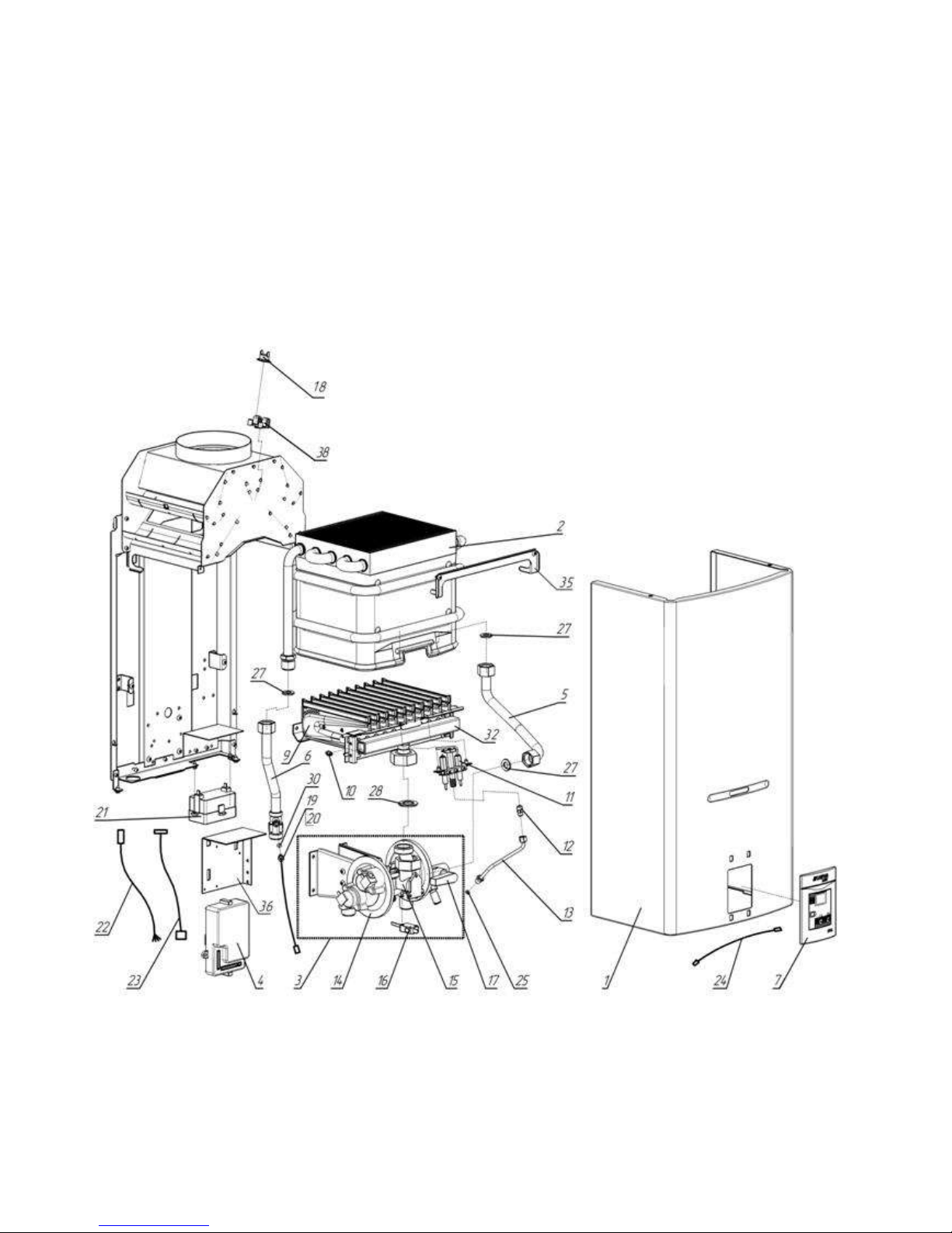
Technical staff manual
31
Annex I Scheme of the appliance with separated components
@
Scheme 15. Appearance of the appliance “BaltGaz NEVALUX -6011” with separated parts
Page 40
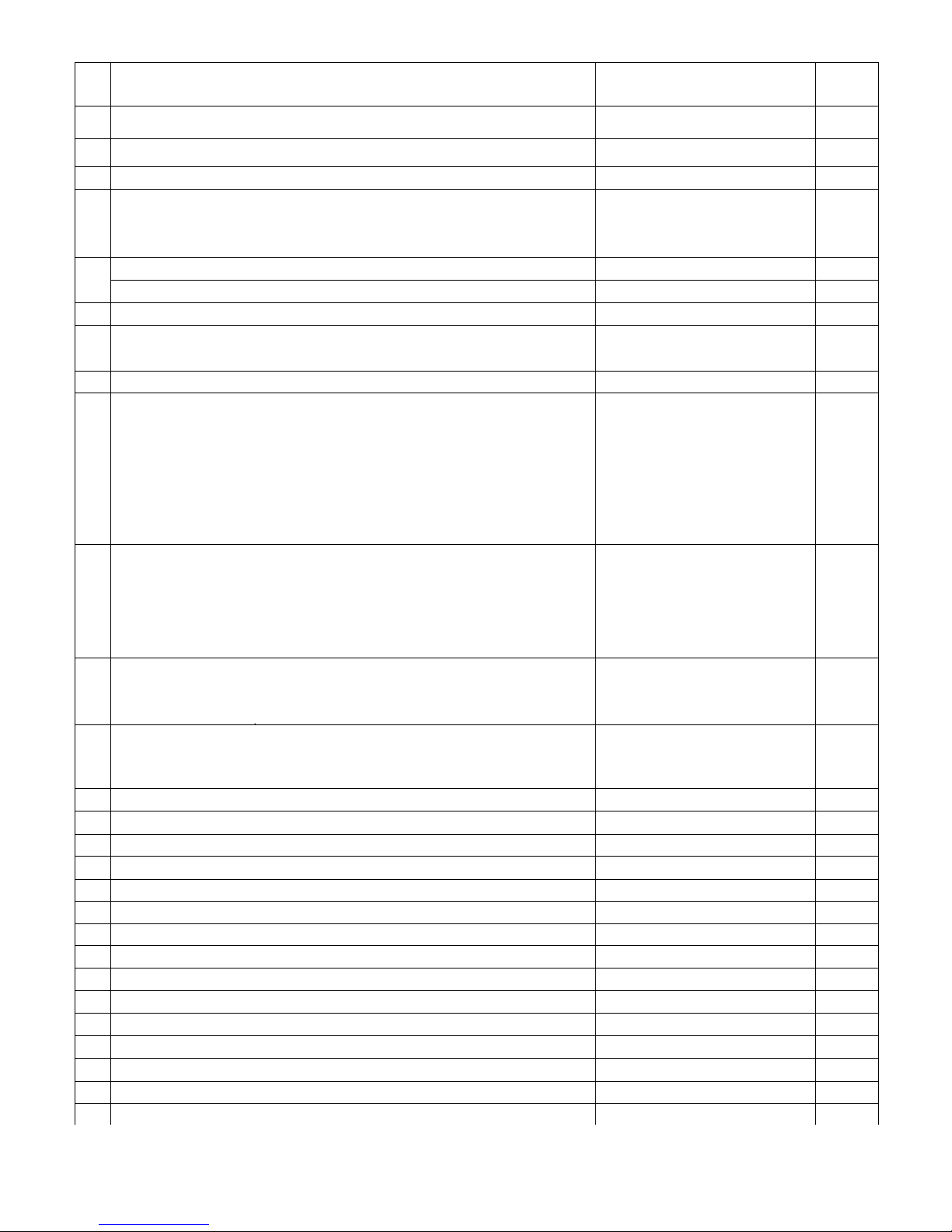
Technical staff manual
Pos.
Name
Designation
Quantity.
1
Casing’
3270-03.000-01
1
2
Heat exchanger*
3272-07.000
1
3
Water and gas unit*
3273-02.250
1
4
Electronic control block'
Natural gas
3226-07.000
3226-07.000-01
1
5
Pipe* (from the water unit to the heat exchanger, copper)
3270-04.000-01
1
Pipe* ( from the water unit to the heat exchanger , steel)
3273-08.000
1
в
Pipe’ (hot water outlet, copper)
3273-05.000-01
1
7
Plate with the display PCB*
Light grey
3273-20.00
1
8
Membrane with a plate* (water unit repair set)
3224-22.00
1
9
Burner* (10 blades)
Natural gas (G20. 2nd family, group Н). 1.3 kPa (130 mm w.g.)(D 1.28)
Natural gas (G20.2nd family, group Н). 2.0 kPa (200 mm w.g) (D 1.14)
Liquefied gas (G30.3rd family, group В/Р). 2.9 kPa (300 mm w.g.) (D 0.79)
3272-02.100
3272-02.100-02
3272-02.100-01
1
10
Nozzle* (of the main burner)
Natural gas (G20. 2nd family, group Н). 1.3 kPa (130 mm w.g .) (D 1.28)
Natural gas (G20. 2
nd
family, group Н). 2.0 kPa (200 mm w.g ) (D 1.14)
Liquefied gas (G30.3
rd
family, group В/Р). 2.9 kPa (300 mm w.g) (D 0.79)
3295.07.20.005-13
3295-07.20.005-10
3295-07.20.005-20
10
11
Ignition burner*
Natural gas (G20. 2nd family , group Н)
3224-11.00
3224-11.00-01
1
12
Ignition burner’s nozzle*
Natural gas (G20. 2nd family , group Н) (D 0,55)
3224-11.02
3224-11.02-01
1
13
Flame igniter’s pipe*
3270-07.000
1
14
Valve block*
3226-02.300
1
15
Gas unit*
3226-02.400
1
16
Micro switch*
3224-21.00
1
17
Water unit*
3224-27.00 (STG-W4P)
1
18
Thermo relay 90'С*
3264-26.00
1
19
Water temperature sensor*
3226-10.000
1
20
Fitting*
3226-10.001
1
21
Battery section*
3224-26.00
1
22
Cable*
3226-00.040
1
23
Cable*
3226-00.060
1
24
Cable*
3226-00.080
1
25
Gasket * C6,5xd3x1
3224-04.02
1
26
Gasket * D17xd8x3 (gas valve)
3226-02.405
1
27
Gasket * D19xd10x2
3103-00.014
3
Page 41
Technical staff manual
28
Gasket * D28*d17x3.0or D28xd22x1.5
3219-00.07 or 3224-00.07
1
29
Gasket * D28xd22x2 (connection of the gas inlet pipe with the gas unit
3224-04.03
1
30
Ring* d3x1.7
3226-10.002
1
32
Manifold in the assembly*
Natural gas (G20, 2nd family, group Н). 1.3 kPa (130 mm w.g.)(D 1.28)
Natural gas (G20, 2nd family, group Н). 2.0 kPa (200 mm w.g.) (D 1.14)
Liquefied gas (G30, 3rd family, group В/Р). 2.9 kPa (300 mm w.g.) (D 0.79)
3272-02.120
3272-02.120-02
3272-02.120-01
1
33
Ring * d18x2.5 (Connecting the valve block to the gas unit)
3224-18.01 or 018-022-25-2-4
GOST 9833-90
1
34
Gasket* d31xd20x2 (connecting the adaptor to the gas unit)
3224-00.06
1
35
Plank
3272-00.004
1
36
Carrier
3273-02.001
1
38
Carrier
3295.07.00.001
1|
* Supplied as spare parts.
Table 8. Spare parts catalogue of the appliance «BaltGazNEVALUX-6011»
«Armavirsky Plant of Gas Equipment"»Ltd.
352902, Russia, Krasnodar Krai, Armavir,
Turgeneva street, 319
tel. (86137) 4-03-83
 Loading...