

Page 1

2016
BALTECH VP-3450
device for bearing diagnostics
using shock pulse method
OPERATION MANUAL
Page 2

Device for bearing diagnostics using shock pulse method
Operation manual
Before you start using the device for bearing diagnostics using shock
pulse method read this operation manual carefully. Baltech doesn’t
bear responsibility for any damages occurred due to nonobservance
of the instructions given in this operation manual.
The information contained in this operation manual is subject to change
without notice.
It is strictly forbidden to use, copy or translate this operation manual without
prior written consent of Baltech.
The publisher doesn’t bear responsibility for any damages, direct or indirect,
that might be originated from use of the information contained in this
operation manual.
Copyright BALTECH, 2013.
BALTECH registered trademark
Page 3

Device for bearing diagnostics using shock pulse method
Operation manual
Content
3
Content
Content............................................................................................................. 3
Table of figures ............................................................................................... 4
1. Introduction ................................................................................................. 5
1.1. Conventions .......................................................................................................................... 5
2. Safety requirements .................................................................................... 6
3. Technical description ................................................................................. 7
3.1. Application ............................................................................................................................ 7
3.2. Technical characteristics ...................................................................................................... 8
3.3. Delivery set ........................................................................................................................... 8
3.4. Design and operation ............................................................................................................ 9
3.4.1. Operation principles ........................................................................................................... 9
3.5. Marking, preservation and packing ..................................................................................... 13
4. Operation ................................................................................................... 14
4.1. Operation conditions: .......................................................................................................... 14
4.2. Preparation to operation ..................................................................................................... 14
4.2.1. Unpacking and installation ............................................................................................... 14
4.2.2. Operation modes ............................................................................................................. 15
4.3. Use of the tester BALTECH VP-3450 ................................................................................. 20
4.3.1. Establishment of equipment monitoring system .............................................................. 20
4.3.2. Measurement procedure .................................................................................................. 21
4.3.3. Information analysis ......................................................................................................... 24
5. Maintenance .............................................................................................. 31
5.1. Tester cleaning ................................................................................................................... 31
5.2. Battery replacement ............................................................................................................ 31
6. Storage and transportation ...................................................................... 32
7. Warranty ..................................................................................................... 33
Page 4

Device for bearing diagnostics using shock pulse method
Operation manual
4
Table of figures
Table of figures
Figure 3-1. Appearance………………………………………………………………………….............7
Figure 3-2. Bearing wear development………………………………………………………………..9
Figure 3-3. Shock pulse dB values……………………………………………………………………..10
Figure 3-4. Control elements…………………………………………………………………………….11
Figure 4-1. Direct change of the initial dBi value…………………………………………………16
Figure 4-2. Setting rpm and diameter. Step 1…………………………………………………….16
Figure 4-3. Setting rpm and diameter. Step 2…………………………………………………….17
Figure 4-4. Shock pulse measurement……………………………………………………………….17
Figure 4-5. Measurement range set…………………………………………………………………..19
Figure 4-6. Headphone mode……………………………………………………………………………20
Figure 4-7. Measurement point selection……………………………………………………………22
Figure 4-8. Follow-up form……………………………………………………………………………….23
Figure 4-9. Bearing good condition......................................................................25
Figure 4-10. Bearing damage at an early stage of development…………………………..26
Figure 4-11. Bearing with severe damage………………………………………………………….26
Figure 4-12. Periodic shock pulses…………………………………………………………………….27
Figure 4-13. Cyclic shock pulses………………………………………………………………………..27
Figure 4-14. Improper lubrication mode…………………………………………………………….28
Figure 4-15. Cavitation or similar problems………………………………………………………..28
Figure 4-16. Irregular measurement results……………………………………………………….29
Figure 4-17. Inconsistent shock pulse values of damaged bearings………………………30
Page 5

Device for bearing diagnostics using shock pulse method
Operation manual
Section 1 Introduction
5
1. Introduction
This operation manual is intended to familiarize users with application, design,
operation principle, operation instructions, measurement performance, safety
requirements and requirements to transportation and storage of the device for bearing
diagnostics using shock pulse method BALTECH VP-3450.
Note
Baltech wants our customers to be satisfied with the device for bearing
diagnostics using shock pulse method BALTECH VP-3450. Therefore if you
have any questions do not hesitate to address to us at any time.
1.1. Conventions
Below are the conventions used in this operation manual and intended to
emphasize the text.
Note
Note paragraphs contain special comments and instructions.
Attention!
Attention paragraphs warn you about actions that can injure you or the
device.
Caution!
Caution paragraphs warn you about actions that can result in serious injury or
the device damage.
Page 6

Device for bearing diagnostics using shock pulse method
Operation manual
6
Section 2 Safety requirements
2. Safety requirements
When working with the tester strictly observe the safety requirements.
Caution!
Nonobservance of the safety requirements may result in serious injury or
failure of the device. Strictly observe the following requirements:
Do not use the device if it has any damages;
Use the device only for its intended purposes.
Page 7

Device for bearing diagnostics using shock pulse method
Operation manual
Section 3 Technical description
7
3. Technical description
3.1. Application
The device for bearing diagnostics using shock pulse method BALTECH VP3450 (Figure 3-1) is intended to perform monitoring of rolling bearings of
rotatory machinery, check of equipment mechanical condition for mechanical
damages.
Figure 3-1. Appearance.
Page 8

Device for bearing diagnostics using shock pulse method
Operation manual
8
Section 3 Technical description
3.2. Technical characteristics
Table 3-1
Characteristics
Value
Measurement range, dBsv
-9 ~ 99
Resolution, dBsv
1
Maximum absolute error, ≤dBsv
±2
Supply voltage , V
9
Dimensions, mm
255х105х60
Weight, kg
0,8
3.3. Delivery set
Table 3-2
No.
Name
Q-ty
Appearance
1
Measurement unit
1
2
Sensor with cable
1
3
Headphones
1
4
Screw driver
1
5
Battery, АА
6
6
Checklist
1
7
Operation manual
1
8
Transportation case
1
9
Package
1
Page 9
Device for bearing diagnostics using shock pulse method
Operation manual
Section 3 Technical description
9
3.4. Design and operation
3.4.1. Operation principles
Shock pulse method
Installation, operation, repair and maintenance are main factors that influence
bearing life. Periodic bearing monitoring during its operation is the best way
to prevent damage and costly repair. There are several bearing monitoring
methods: temperature measurement, vibration measurement, sound
measurement and shock pulse method. The shock pulse method allows
measuring bearing condition during normal bearing operation without
influence of vibration generated by a machine or bearing. The shock pulse
method allows timely detecting bearing defects resulted from improper
manufacture, improper assembly, improper lubrication and scratches on
rotation surfaces.
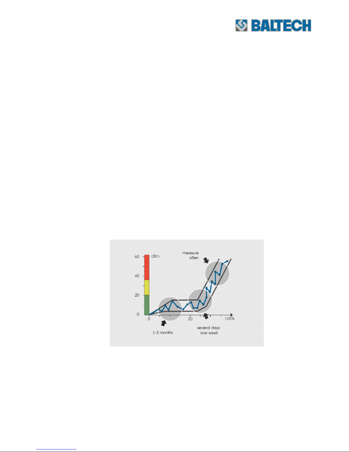
Bearing condition is determined by the shock pulse method as follows: initially
a new bearing has a low shock pulse value and if this value increases up to
1,000 times of the initial shock pulse value, it means that the bearing life has
expired.
Figure 3-2. Bearing wear development.
Shock pulse strength depends on a shock velocity V, if A represents a peak
shock value, then there is a relation of A = f (V), while the shock velocity V
also depends on a bearing size, rotation speed and defect size.
Page 10

Device for bearing diagnostics using shock pulse method
Operation manual
10
Section 3 Technical description
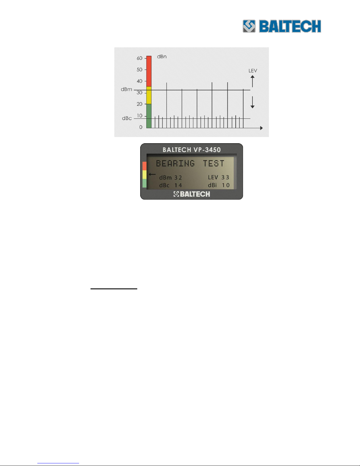
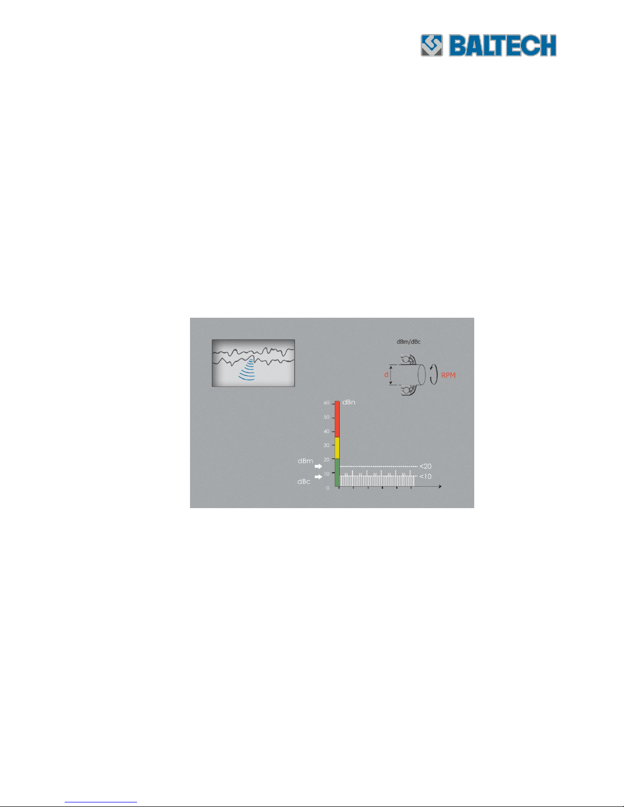
The shock pulse method uses several decibel values (Figure 3-3):
Figure 3-3. Shock pulse dB values.
dBsv (dB-shock value) –the absolute shock pulse dB value.
dBi (dB-initial)- the initial dB value. This is an average value obtained from
a variety of tests and measurements conducted on new bearings, and
correction of different bearing operation and their rotation speed according to
the dBn standard.
dBn (dB-normalized)- the standard dB value. It is a standardized
measurement and scale unit used as a standard to estimate bearing condition.
dBm (dB-maximum value)- the maximum dB value obtained from a
bearing shock pulse measurement and used to measure the bearing damage
severity.
dBc (dB-carpet value)- the carpet dB value used to measure bearing
surface roughness, installation and lubrication condition.
Page 11

Device for bearing diagnostics using shock pulse method
Operation manual
Section 3 Technical description
11
Tester description
The BALTECH VP-3450 tester consists of the electronic unit and sensor. The
sensor mounted in the handle is connected to the device via the cable. The
tester has a housing made of ABS plastic and consists of a single-chip
microcontroller, LCD and film keyboard on the front panel. The batteries are
in the battery cabinet. The battery cabinet cover is fixed with screws. The
outputs for the sensor and headphones are on the bottom panel.
During measurement the sensor is connected to the tester via the cable and is
pressed to the bearing cover with the probe.
Appearance and control elements
The appearance of BALTECH VP-3450 and its control elements are shown on
the Figures 3-1 and 3-4.
Figure 3-4. Control elements.
1. Display
2. Condition scale
3. Pulse indicator
Page 12

Device for bearing diagnostics using shock pulse method
Operation manual
12
Section 3 Technical description
4. Measuring key (M)
5. Navigation key (Right)
6. Set key (SET)
7. Navigation key (UP)
8. Navigation key (Down)
9. Output for shock pulse sensor (SPM)
10. Output for headphones (EAR)
1. Display
The display shows menu, input information and measurement results.
2. Condition scale
Current condition is determined by the shock pulse method according to the
scale color: green, yellow and red:
Green – Good condition;
Yellow – Warning;
Red – Damage.
3. Pulse indicator
The pulse indicator flashes when peak values exceed the defined shock pulse
range. The measurement range should be set prior to the shock pulse
measurement. The indicator will stop flashing.
4. Measuring key
The M key is used for a single measurement. For continuous measurement
press and hold this key.
5. Navigation key (Right)
Press this key to move right.
Page 13

Device for bearing diagnostics using shock pulse method
Operation manual
Section 3 Technical description
13
6. Set key
The SET key is used for data input and headphone volume adjustment.
7/8. Navigation key (Up) and navigation key (Down)
These keys are used for adjustment of volume and measurement range.
3.5. Marking, preservation and packing
The tester is marked with a serial number, which is specified in the technical
specifications of the device along with the assembly and packing date.
The tester is packed in the transportation case, which is a part of the delivery
set.
Page 14

Device for bearing diagnostics using shock pulse method
Operation manual
14
Section 4 Operation
4. Operation
4.1. Operation conditions:
Ambient conditions:
Ambient temperature: 0…+50 ºС
Relative humidity at 25 °С: ≤80%
The tester is powered from the alkali batteries 1.5 V, type LR6 (AA). Nickelmetal-hydride or nickel-cadmium batteries can be also used. The continuous
operation time without the battery replacement reduces considerably.
4.2. Preparation to operation
4.2.1. Unpacking and installation
To unpack the tester open the transportation case and take out the required
components.
Before you start using the tester:
Check all the tester components for any damages and contamination. If
necessary, perform actions mentioned in the section 5 “Maintenance”.
Attention!
Do not use the tester if it has any damages.
Check the tester components according to the paragraph 3.3. “Delivery
set”.
Page 15

Device for bearing diagnostics using shock pulse method
Operation manual
Section 4 Operation
15
4.2.2. Operation modes
GENERAL FUNCTIONS
Tester on/off:
Press any function key to switch on the BALTECH VP-3450 tester. The tester
shuts down automatically in 30 seconds after the last pressing of any key.
Sensor and headphone connection
A screw BNC connector (9) is used to connect the shock pulse sensor, the
output (10) is used to connect the headphones; once headphones are
connected the headphone mode is activated; disconnect the headphones from
the tester if you want to exit the headphone mode.
Memory
When the tester is shut down the following information is saved: the last
shock pulse reading (dBm, dBc, dBi), arrow position on the condition scale;
press the SET key to change settings, the last reading or arrow position on
the condition scale will not be changed; press the M key to perform a new
measurement.
SHOCK PULSE MEASUREMENT
The standard shock pulse reading (dBN) displays a bearing condition. The
initial bearing dBi value should be input before measurement; VP-3450
received the dBi value within the range 9~40dBi; the absolute dBsv value
measurement is used to adjust ranges.
When dBi is lower than -9 the display shows “--”(two hyphens).
Initial dBi value setting
There are two methods to set the initial dBi value:
1) Direct change of the initial dBi value
Press the SET key to open the menu. The cursor will flash on the current
dBi value (Figure 4-1).
Page 16

Device for bearing diagnostics using shock pulse method
Operation manual
16
Section 4 Operation
Figure 4-1. Direct change of the initial dBi value.
Press the UP key to increase the dBi value and the DOWN key to decrease
the dBi value;
Press the M key to exit the setting mode.
2) Setting rpm and diameter
Press the SET key to open the menu.
Press the SET key again to move the cursor to the rpm input field. Input
the rpm value. Use the RIGHT key to move from one digit to another. The
maximum rotation speed is 19,999 rpm (Figure 4-2).
Figure 4-2. Setting rpm and diameter. Step 1.
Press the SET key to move the cursor to the diameter input field;
Input a diameter value. Use the RIGHT key to move from one digit to
another. The maximum diameter value is 1999 mm;
Press the SET key to display the dBi value (Figure 4-3).
Page 17

Device for bearing diagnostics using shock pulse method
Operation manual
Section 4 Operation
17
Figure 4-3. Setting rpm and diameter. Step 2.
Press the M key to exit the setting mode.
Note
When dBi is lower than -9 or higher than 40, the display shows “--” (two
hyphens).
Shock pulse measurement:
Switch on the tester BALTECH VP-3450, the last reading and dBi value will be
displayed.
If necessary, change the dBi value
Move the sensor to a measurement point;
Press the M button.
Figure 4-4. Shock pulse measurement.
Page 18

Device for bearing diagnostics using shock pulse method
Operation manual
18
Section 4 Operation
Within a few seconds a new maximum value dBm and carpet value dBc will be
displayed on the screen; these values will be displayed on the screen until the
M key is pressed to perform another measurement.
If the dBi value is set, the tester measures the standard values and the result
is indicated on the screen by the arrow.
Green – Good condition (0~20 dBN)
Yellow – Warning (21~34 dBN)
Red – Damage
When dBi is not set, the tester will measure the absolute decibel value and
the arrow is not displayed.
Press and hold the M key, the measurement results shown on the screen will
be updated once in a few seconds until the M key is released.
MEASUREMENT RANGE SET
In the operation mode the tester continuously compares the measured shock
pulse values with the last displayed dBm value. When the shock pulse value is
higher than the displayed dBm, the pulse indicator flashes. If the dBm value is
high (in yellow or red areas) and the pulse indicator flashes frequently, it is
recommended to re-measure or to change the measurement range.
Press the UP key to increase the measurement range. Measurement step is
one decibel. The initial level corresponds to the last measured dBm value. If
the pulse indicator stops flashing, it means that the shock pulse values are
within the current measurement range.
Page 19
Device for bearing diagnostics using shock pulse method
Operation manual
Section 4 Operation
19
Figure 4-5. Measurement range set.
Press the DOWN key to reduce the measurement range, the more pulses
exceed the defined measurement range, the more frequently the pulse
indicator flashes. If the measurement range is close to the dBс value, the red
pulse indicator is red.
HEADPHONES
To determine a shock pulse source the headphones can be used. The
operation principle of the headphones is as follows- if the shock pulse value is
higher than the measurement range, the pulse is audible; If the measuring
range is higher than the largest shock pulse value, the pulse is inaudible. The
more pulses exceed the measurement range, the more frequent the pulse
occurs. When the range is close to dBc, the sound in the headphones
becomes continuous.
If you want to exit the headphone mode disconnect the cable from the tester
BALTECH VP-3450.
The measurement range is in dBsv.
Page 20

Device for bearing diagnostics using shock pulse method
Operation manual
20
Section 4 Operation
Volume adjustment:
To adjust volume press the SET key when the headphones are is
connected, the volume level can be changed with the UP/DOWN keys
from 1 to 10 (Figure 4-6).
Press the M key to return to the headphone mode.
Figure 4-6. Headphone mode.
4.3. Use of the tester BALTECH VP-3450
4.3.1. Establishment of equipment monitoring system
In order to obtain accurate and reliable readings using the tester BALTECH
VP-3450 two main requirements should be met:
• Choose a measurement point according to SPM rules;
• Calculate a correct initial dBi value according to a bearing diameter and
rpm.
There are conditions under which the shock pulse measurement doesn’t
provide reliable results:
Low rotation frequency or irregular loads;
Interference from other pulse sources;
Quick damage process;
Page 21

Device for bearing diagnostics using shock pulse method
Operation manual
Section 4 Operation
21
To ensure efficient bearing monitoring the following conditions should be met:
Careful preparation for obtaining effective initial values of good bearing
and equipment condition;
Planned and perfect procedure of periodic data collection;
All-around evaluation of any result deviating from the good condition
4.3.2. Measurement procedure
Application
The measurement range of BALTECH VP-3450 allows measuring bearings with
the maximum rotation frequency up to 19,999 rpm and maximum dBi 40.
The minimum dBi value is -9dBi; the real limit is 0 dBi, as in case of low
values for low-speed bearings it is almost not possible to obtain useful
information on the bearing condition.
Measurement range
Normally, a bearing damage develops very slowly, and a measurement
interval is determined according to the following rules:
• Bearings should be inspected at least once a month;
• Critical equipment and heavily loaded bearings shall be measured more
frequently than standard bearings;
• Bearings should be monitored more frequently if their measuring values
are not stable;
• Damaged bearings should be monitored as frequently as possible.
Note
After bearing lubrication at least one hour should go by before start operating
it.
Page 22
Device for bearing diagnostics using shock pulse method
Operation manual
22
Section 4 Operation
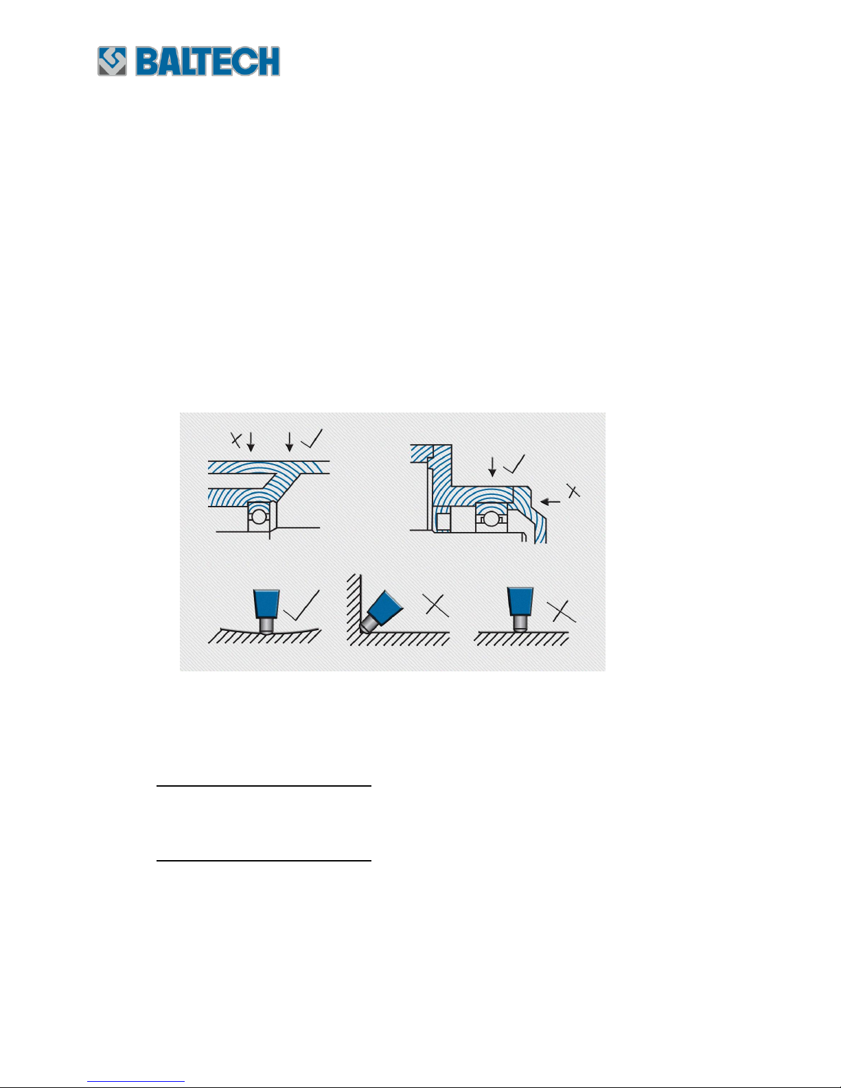
Measurement point selection
To obtain a correct measurement signal, a measurement point should be
selected according to the following rules (Figure 4-7):
Distance from the bearing to the measurement point should be direct
and as low as possible;
Not more than one mechanical component should be between the
bearing and the measurement point;
The measurement point should be in the bearing loaded area (in most
cases upper part of the bearing).
Figure 4-7. Measurement point selection.
If the measurement point doesn’t correspond to the above requirements, the
condition scale will not correspond to true values.
Determine the strongest signal: use the probe to determine a point with the
strongest signal, if there are several points with the same signal level, select
the easiest point to obtain readings.
Mark the measurement point: the measurement point should be clearly
marked so that obtained readings are comparable.
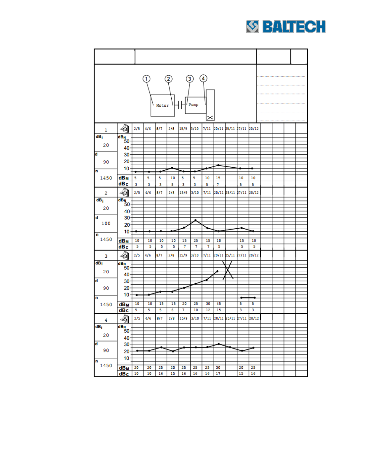
Follow-up form (Figure 4-8)
This follow-up form allows detecting a bearing condition. As opposed to a
single measurement, periodic measurements of the damaged bearing over a
period of time is more reliable base for planning of repair and maintenance.
Page 23
Device for bearing diagnostics using shock pulse method
Operation manual
Section 4 Operation
23
Figure 4-8. Follow-up form.
Page 24

Device for bearing diagnostics using shock pulse method
Operation manual
24
Section 4 Operation
The follow-up form contains the following information:
1. Equipment description, name, number, position;
2. Display of measurement points, their position and number;
3. Notes;
4. Measurement point number;
5. Initial dBi value;
6. Bearing diameter;
7. Rotation frequency;
8. Measurement date;
9. Measurement result trend (dBm, dBc);
10. Measurement results (dBm, dBc).
4.3.3. Information analysis
Data process and analysis
For correct data process and analysis the information you provide to
maintenance personnel should be detailed and reliable.
During measurements you should consider that some machines contain shock
pulse sources. Besides, bad bearing condition may be resulted from lots of
reasons other than damage; therefore during the data process and analysis
you should use pulse indicator, probe, headphones and your own knowledge
in order to avoid misinterpretation.
The data process and analysis are necessary in the following conditions:
During the first check of a new bearing it is necessary to make sure
that the received initial values are reliable.
In case of considerable change of shock pulse values it is necessary to
determine the reason of such changes - improper installation, improper
lubrication, overload or damage so that to determine what
maintenance work should be done.
Page 25
Device for bearing diagnostics using shock pulse method
Operation manual
Section 4 Operation
25
To make sure that the measured information is correct:
Check the defined rpm and diameter, dBi settings.
If the pulse indicator flashes, continue to measure dBm and dBc values to
obtain the correct data.
Standard bearing operation modes
а) Bearing good condition (Figure 4-9).
The dBm value of the good bearing is lower than 20 dB, the dBc value –
within the range 5 ~ 10 dB. If these values are very low, it can indicate
incorrect measurements, for example, in case of improper measurement point
or bearing no-load running.
Figure 4-9. Bearing good condition.
b) Bearing damage at an early stage of development (Figure 4-10).
If the dBm value is within 20~35 dB (yellow area) a medium growth of the
dBc value indicates minor bearing surface damages.
At this stage the measurements should be performed more frequently so that
to determine if the bearing is in good working condition or deteriorating.
Page 26

Device for bearing diagnostics using shock pulse method
Operation manual
26
Section 4 Operation
Figure 4-10. Bearing damage at an early stage of development.
с) Bearing with severe damage (Figure 4-11).
If the dBm value is higher than 35dB (red area), dBc and dBm values differ
considerably, the dBm value indicates the bearing damage severity level:
•35~40 dBn: slight damage;
•40~45 dBn: severe damage;
•>45 dBn: breakdown risk.
Figure 4-11. Bearing with severe damage.
Page 27

Device for bearing diagnostics using shock pulse method
Operation manual
Section 4 Operation
27
Another reason can be strong lubrication contamination. Check the oil
condition with the mini – laboratory BALTECH OA-5000. If after the lubrication
change the dBm value decreases a little, it means that the bearing is
damaged.
d) Periodic shock pulses (Figure 4-12).
A periodic shock pulse is typically equal or multiple of the bearing rotation
frequency.
Figure 4-12. Periodic shock pulses.
e) Cyclic shock pulses (Figure 4-13).
A periodic single shock pulse can indicate overload, pressure shock, gear
damage or other impacts.
Figure 4-13. Cyclic shock pulses.
Page 28

Device for bearing diagnostics using shock pulse method
Operation manual
28
Section 4 Operation
f) Improper lubrication (Figure 4-14).
High dBc value indicates bearing operation without lubrication, dBm and dBc
values differ slightly, possible reasons are:
Insufficient lubrication (lubrication of poor quality, use of waste, resin
or condensated oil);
Nonsymmetrical installation or bending;
Emergency shutdown
Change oil or increase oil supply.
Figure 4-14. Improper lubrication mode.
g) Cavitation or similar problems (Figure 4-15).
Shock pulses in case of pump cavitation are the same as in case of improper
lubrication. In this case the highest shock pulse values will be on the pump
housing and on all the bearings.
Page 29

Device for bearing diagnostics using shock pulse method
Operation manual
Section 4 Operation
29
Figure 4-15. Cavitation or similar problems.
h) Irregular measurement results (Figure 4-16).
If low values appear suddenly or if the values disappear, the reasons are:
Improper bearing operation, the sensor is attached to a measurement
object not tightly or damaged.
If the tester and the rolling element bearing are in good condition, and the
bearing have been recently lubricated, such low values can be a result of
slippage between the rotating axis and bearing or between the bearing and
bearing housing.
Figure 4-16. Irregular measurement results.
Page 30

Device for bearing diagnostics using shock pulse method
Operation manual
30
Section 4 Operation
i) Inconsistent shock pulse values of damaged bearings (Figure. 4-17).
Damaged heavy duty needle roller bearings generate a dramatic increase of
shock pulses. With time the damaged surface can be smoothed which will
result in reduction of the shock pulse values. However such bearings are
defect.
Figure 4-17. Inconsistent shock pulse values of damaged bearings.
Page 31

Device for bearing diagnostics using shock pulse method
Operation manual
Section 5 Maintenance
31
5. Maintenance
5.1. Tester cleaning
The tester should be cleaned with a cotton cloth moistened with a mild soap
solution and wiped dry.
5.2. Battery replacement
The tester is powered from alkaline battery 1.5 V (LR6) or from rechargeable
batteries. If the display shows “LOW BATTERY” it means that the battery
should be replaced. Unscrew the screws on the battery cabinet cover, remove
the cover and replace the batteries, observing the polarity.
Page 32

Device for bearing diagnostics using shock pulse method
Operation manual
32
Section 6 Storage and transportation
6. Storage and transportation
During transportation and storage the tester should be packed in the
transportation case. It is recommended to remove the batteries before longterm storage.
Before long-term storage the batteries should be removed.
Page 33

Device for bearing diagnostics using shock pulse method
Operation manual
Section 7 Warranty
33
7. Warranty
The manufacturer guarantees the tester BALTECH VP-3450 to the technical
characteristics in case of the observance of the operation, maintenance, storage and
transportation conditions, specified in the operation manual.
The warranty period is 12 months from the shipment date.
Warranty storage life is 6 months from the production date.
The warranty liabilities cease to be in force:
- if there are visible mechanical damages;
- in case of using improper batteries.
 Loading...