

Page 1
BalTec Maschinenbau AG
Obermattstrasse 65
CH - 8330 Pfäffikon ZH
Phone: +41 (0)44 953 13 33
Fax: +41 (0)44 953 13 44
[email protected]
http:\\www.baltec.com
803699.017/ENG
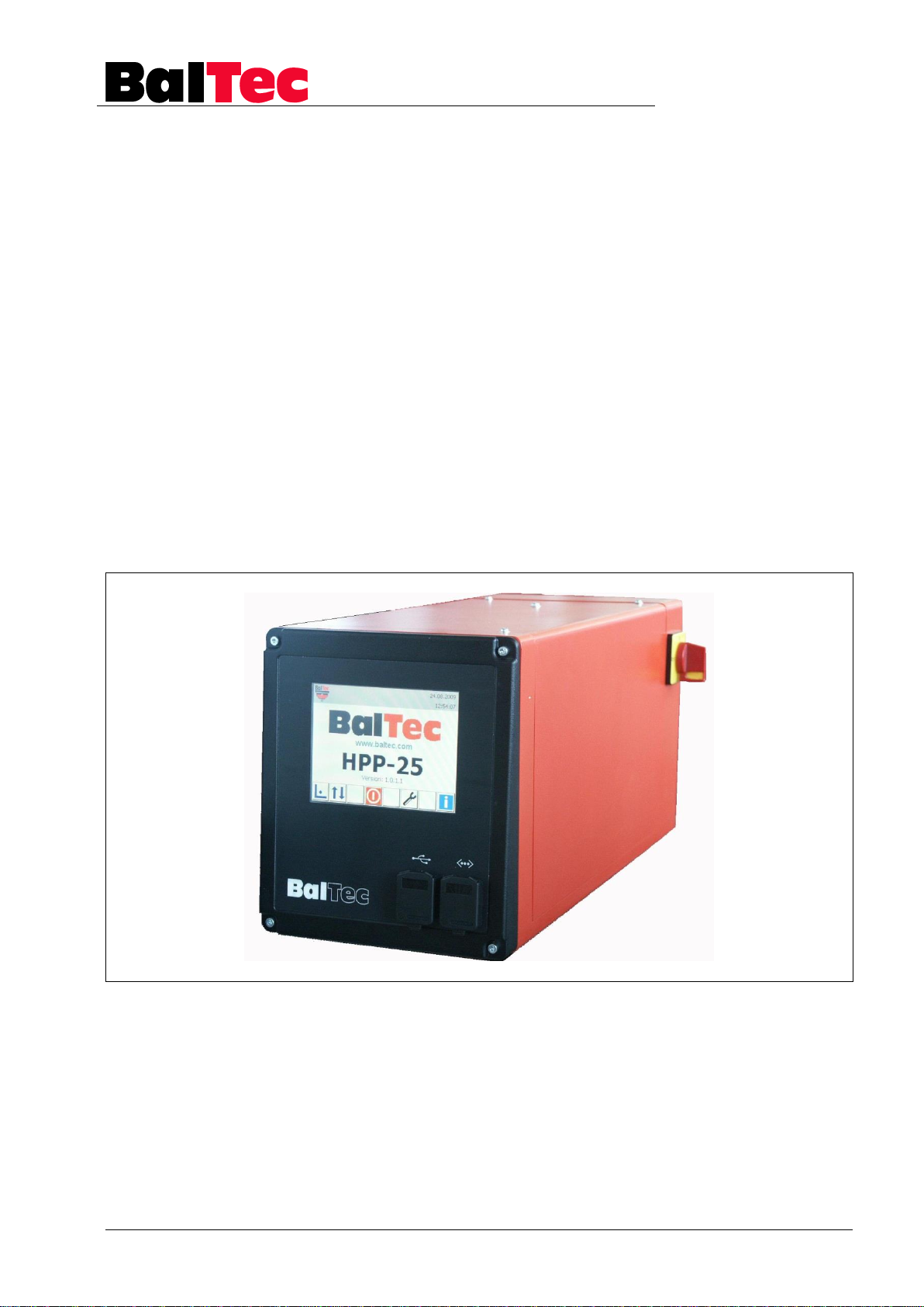
OPERATING INSTRUCTIONS
Process-Controller
HPP - 25
from SW-Version 2.0.1.5
803699.017/ENG
Page 2

Introduction Process-Controller HPP - 25
2
803699.017/ENG
Page 3

Process-Controller HPP - 25 Introduction
803699.017/ENG
3
Contents
1 Introduction ............................................................................................................... 6
2 Safety regulations ..................................................................................................... 7
2.1 Introduction.......................................................................................................................................... 7
2.2 Information and symbols ..................................................................................................................... 7
2.2.1 Warning and safety notices ............................................................................................................ 7
2.3 Safety measures ................................................................................................................................. 8
3 Product description .................................................................................................. 9
3.1 Introduction.......................................................................................................................................... 9
3.2 Technical specifications HPP-25 ...................................................................................................... 10
3.3 Performance Level specifications ..................................................................................................... 10
3.4 Details Process-Controller ................................................................................................................ 11
3.5 Dimensions drawing .......................................................................................................................... 11
3.6 Functional survey .............................................................................................................................. 12
3.7 Touch-Screen survey ........................................................................................................................ 13
3.1 Key survey......................................................................................................................................... 14
3.2 Interface survey ................................................................................................................................. 15
4 Commissioning ....................................................................................................... 16
4.1 Electric supply ................................................................................................................................... 16
4.2 Connecting the control unit ............................................................................................................... 16
5 Operation ................................................................................................................. 17
5.1 Switching-on the Process-Controller ................................................................................................. 17
5.2 Switching-off the Process-Controller ................................................................................................. 17
5.3 Operating modes ............................................................................................................................... 18
5.4 Riveting modes survey ...................................................................................................................... 19
5.4.1 Riveting mode S ........................................................................................................................... 20
5.4.2 Riveting mode T ........................................................................................................................... 21
5.4.3 Riveting mode F ........................................................................................................................... 24
5.4.4 Riveting mode E ........................................................................................................................... 25
5.4.5 Riveting mode N ........................................................................................................................... 26
5.4.6 Riveting mode H ........................................................................................................................... 27
5.5 Creation of a riveting program (Standard) ........................................................................................ 29
5.5.1 Setup operating mode .................................................................................................................. 29
5.5.2 Correction operating mode .......................................................................................................... 30
5.5.3 Save riveting program .................................................................................................................. 31
5.6 Creation of riveting program with projection measurement (riveting modes S2, T5, H8) ................. 32
5.6.1 Adjust touch probe offset ............................................................................................................. 33
5.7 Creation of riveting program (riveting mode H) ................................................................................. 34
5.7.1 Reference height correction in H-mode ....................................................................................... 35
5.8 Creation of riveting program with external NA detection .................................................................. 36
5.9 Working with existing riveting program ............................................................................................. 36
5.9.1 Cycle operating mode .................................................................................................................. 36
5.9.2 Modify/copy riveting program ....................................................................................................... 37
5.10 Riveting programs special functions ................................................................................................. 39
5.10.1 Asymmetric tolerances ................................................................................................................. 39
5.10.2 Manual trigger TR ........................................................................................................................ 39
5.10.3 Analog value AN for pressure or speed selection ........................................................................ 40
5.10.4 Form factor FF ............................................................................................................................. 41
5.10.5 Control variable offset value (OS) ................................................................................................ 42
5.10.6 Rapid speed/working speed valve output switching point (SP) relative to control variable ......... 43
Page 4

Introduction Process-Controller HPP - 25
4
803699.017/ENG
5.10.7 Rapid speed/working speed valve output switching point (SP) relative to spindle path E .......... 44
5.10.8 Riveting timeout (TX)................................................................................................................... 45
5.10.9 Rivet detection NX ....................................................................................................................... 46
5.10.10 Rivet and component detection ................................................................................................... 47
5.10.11 Tolerance abort ........................................................................................................................... 48
5.11 Tools ................................................................................................................................................. 49
5.11.1 HPP-25 Setup ............................................................................................................................. 50
5.11.1.1 Password levels PWL .............................................................................................................50
5.11.2 HPP-25 configuration .................................................................................................................. 51
5.11.3 Alarm-History ............................................................................................................................... 53
5.11.4 Execute function .......................................................................................................................... 54
5.11.5 Save programs/setup .................................................................................................................. 55
5.11.6 Load parameters ......................................................................................................................... 55
5.11.7 Load programs ............................................................................................................................ 56
5.11.8 Choose language ........................................................................................................................ 56
5.11.8.1 Date and time adjustement .....................................................................................................57
5.11.9 Screen contrast adjustment ........................................................................................................ 57
5.12 Information........................................................................................................................................ 58
5.12.1 Logger data ................................................................................................................................. 59
5.12.1.1 Logger data in Excel ...............................................................................................................60
5.12.2 Riveting curve display ................................................................................................................. 62
5.12.3 Diagnosis inputs and outputs sensor system .............................................................................. 63
5.12.4 Information: riveting, hours, SW, HW .......................................................................................... 64
5.12.5 Enter password ........................................................................................................................... 64
6 Options .................................................................................................................... 65
6.1 PLC Interface ................................................................................................................................... 65
6.2 PLC Interface with function for pneumatic sliding table ................................................................... 66
6.3 PVM module ..................................................................................................................................... 67
6.4 Automatic compensation .................................................................................................................. 67
6.5 UDP protocol secured ...................................................................................................................... 67
6.6 Change over from operation with two-hand operating unit to operation with foot switch ................ 68
6.6.1 Key switch ................................................................................................................................... 68
7 Error rectification .................................................................................................... 69
7.1 Introduction ....................................................................................................................................... 69
7.1.1 List of error messages HPP-25 ................................................................................................... 70
7.2 Operating errors ............................................................................................................................... 73
8 Maintenance and repair work ................................................................................ 74
8.1 Introduction ....................................................................................................................................... 74
8.2 Control unit maintenance ................................................................................................................. 74
8.3 Opening the Controller ..................................................................................................................... 75
9 Appendix ................................................................................................................. 76
9.1 Schemata ......................................................................................................................................... 76
9.1.1 Riveting spindle release chain principle diagram ........................................................................ 77
9.1.2 Connection diagram plug X1 ....................................................................................................... 78
9.1.3 Connection diagram plug X2, Foot switch................................................................................... 78
9.1.4 Connection diagram plug X2, Two-hand operating unit relay ..................................................... 79
9.1.5 Connection diagram plug X2 HST (Manual sliding table) ........................................................... 80
9.1.6 Connection diagram plug X3 ....................................................................................................... 81
9.1.7 Connection diagram plug X4 ....................................................................................................... 81
9.1.8 Connection diagram plug X5, pressure control valve ................................................................. 82
9.1.9 Connection diagram plug X5, Volume flow regulating valve, Rapid speed/working speed valve,
Initiator BDC ................................................................................................................................ 83
9.1.10 Connection diagram plug X6 ....................................................................................................... 83
9.1.11 Connection diagram plug X7, finger guard device ...................................................................... 84
Page 5

Process-Controller HPP - 25 Introduction
803699.017/ENG
5
9.1.12 Connection diagram plug X7 HST/RNR....................................................................................... 85
9.1.13 Connection diagram plug X8, key switch two-hand operating unit/foot switch ............................ 86
9.1.14 Connection diagram plug X9 ........................................................................................................ 87
9.1.15 PLC-Interface Step sequence diagram ........................................................................................ 88
9.1.16 Connection diagram X11, X12, X13, X14 .................................................................................... 89
9.1.16.1 Lower pressure X11 ................................................................................................................ 89
9.1.16.2 Upper pressure X12 ................................................................................................................ 89
9.1.16.3 Path measurement X13 .......................................................................................................... 89
9.1.16.4 Switch NHE X14 ..................................................................................................................... 90
9.1.17 Connection diagram plug X20, X21, X22 ..................................................................................... 91
9.1.18 Wiring diagram Supply, Motors HPP-25 pneumatic .................................................................... 92
9.1.19 Wiring diagram Supply, Motors monophase HPP-25 pneumatic ................................................ 93
9.1.20 Wiring diagram Supply, Motors with thermal overload HPP-25 pneumatic ................................. 94
9.1.21 Wiring diagram Supply, Motors HPP-25 hydraulic ....................................................................... 95
9.1.22 Wiring diagram Supply, Motors with thermal overload HPP-25 hydraulic ................................... 96
9.2 Spare parts lists ................................................................................................................................ 97
9.2.1 Process-Controller HPP-25, 826337-d ........................................................................................ 97
9.3 Setup-Table SW Version from 2.0.1.5 ............................................................................................ 102
10 Index....................................................................................................................... 111
Page 6

Introduction Process-Controller HPP - 25
6
803699.017/ENG
1 Introduction
We are certain that you have made the right choice with our product and thank you
for your trust.
For your personal safety
Before carrying out any activities on or with the Process-Controller, please carefully
read these operating instructions first, in particular the chapter on "Safety
regulations".
Application area of these operating instructions
These operating instructions describe the Process-Controller and provide all
information required for safe operation and maintenance of functionality. Please
keep these operation instructions available at all times for all persons involved with
the riveting machine.
Questions or unclear points
Please contact your supplier immediately if you have any questions or unclear
points. Please provide them with the document number and the page number
located in the footer.
Property rights (Copyright)
Reproduction of these operating instructions - including excerpts - is prohibited.
Without the express written authorization from the manufacturer, nothing may be
reproduced in any form or edited, copied, distributed or translated using any form
of electronic media, in particular photocopiers, photographic, magnetic or other
recording methods.
All rights reserved, in particular the right to reproduction, distribution, translation
and patent or registration rights.
Original language of operating instructions
These operating instructions were originally written in German language.
Page 7
Process-Controller HPP - 25 Safety regulations
803699.017/ENG
7
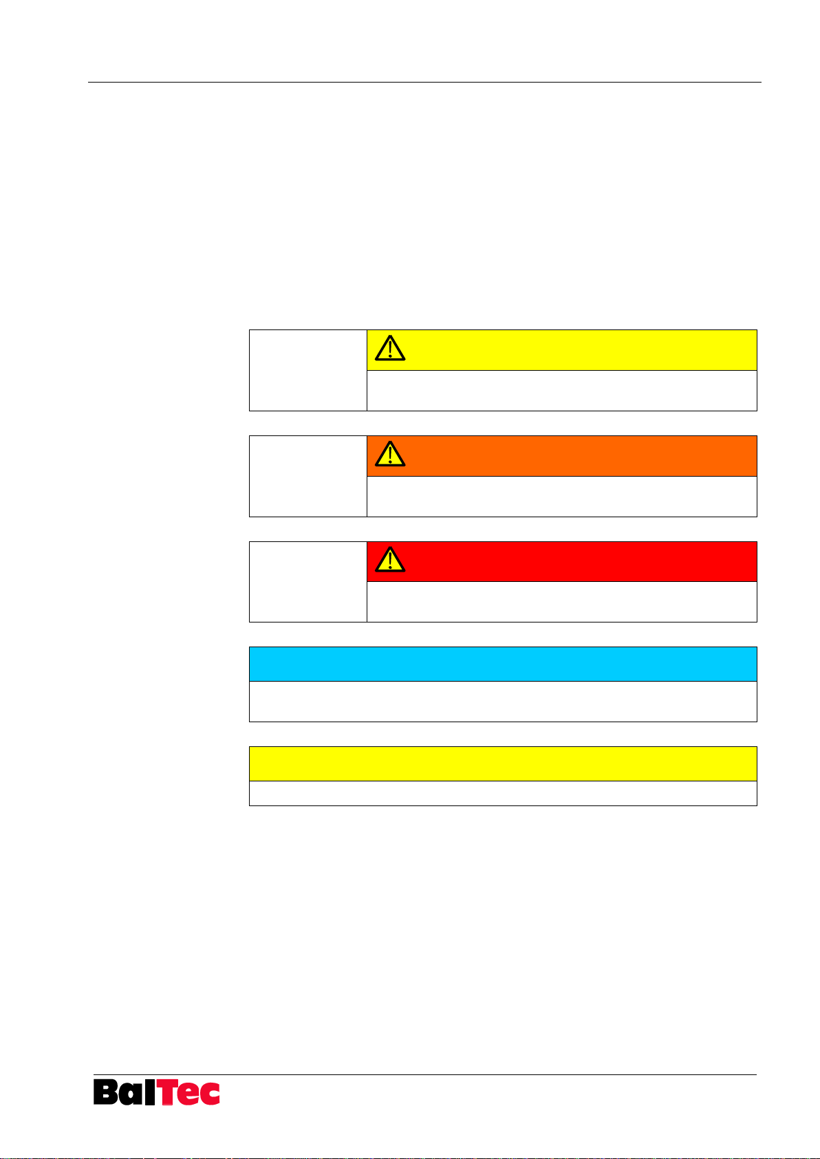
CAUTION
Indicates a hazard with low risk which, if not avoided, could
result in minor or moderate injury.
WARNING
Indicates a possible hazard with medium risk which, if not
avoided, could result in death or serious injury.
DANGER
Indicates an immediate hazard with high risk which, if not
avoided, will result in death or serious injury.
NOTICE
Indicates practical information and tips that permit the best use of machinery,
system or equipment.
CAUTION
To warn of material damage only.
2 Safety regulations
2.1 Introduction
The control unit may only be operated by qualified and appropriately trained
2.2 Information and symbols
2.2.1 Warning and safety notices
personnel for safety reasons.
The warning and safety notices used in these operating instructions have the
following significance:
Page 8
Safety regulations Process-Controller HPP - 25
8
803699.017/ENG
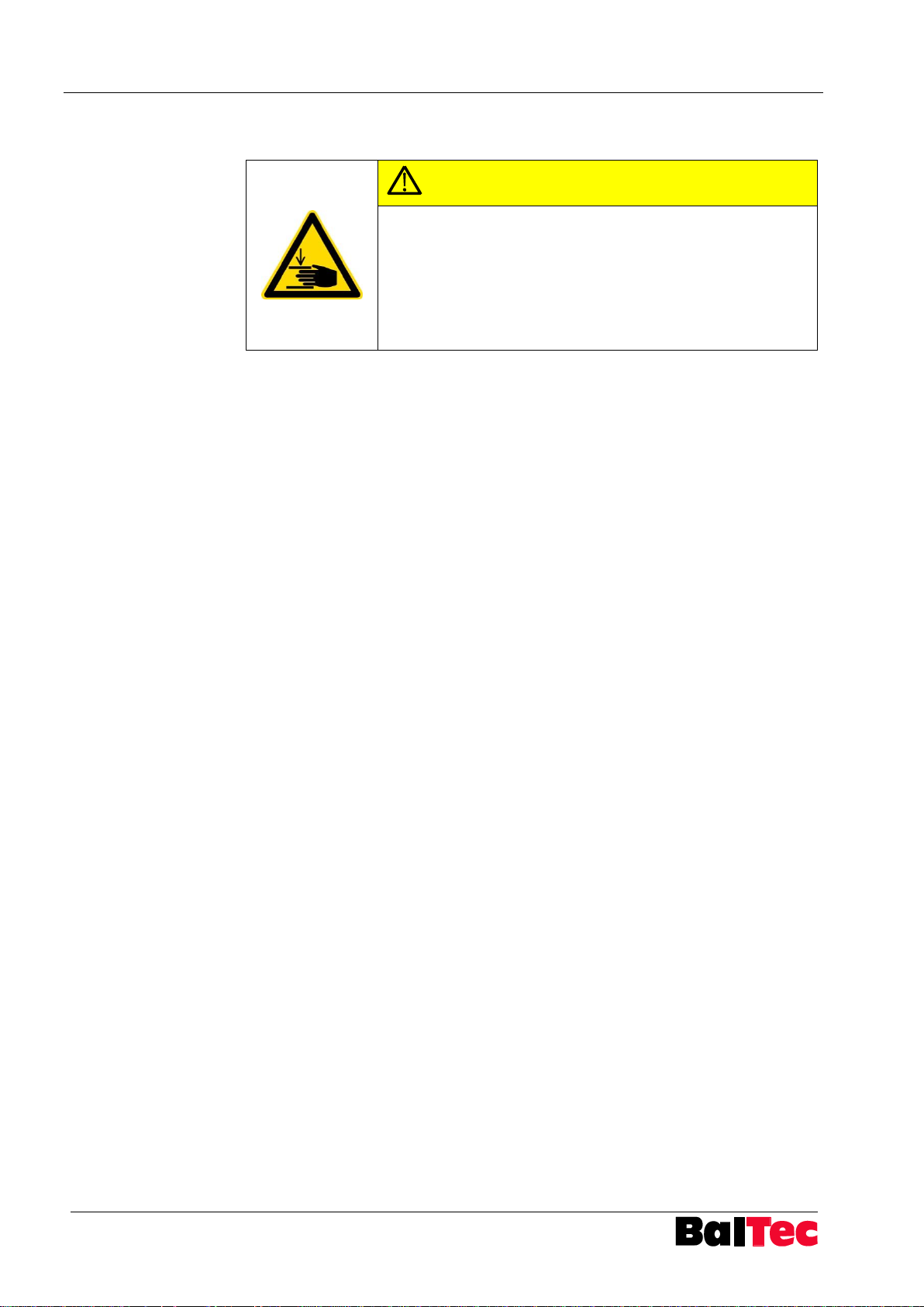
CAUTION
Activation of riveting process with foot
switch or pulse signal!
Danger of hand injuries!
The operator has to take safety measures against the
intervention in danger area (e.g. separative protection
device)!
2.3 Safety measures
Page 9

Process-Controller HPP - 25 Product description
803699.017/ENG
9
3 Product description
3.1 Introduction
The Process-Controller HPP-25 (riveting machine control unit combined with
process control) has been specially designed for the operation of BalTec riveting
machines.
In addition to simple riveting time control the HPP-25 can also control the riveting
modes with values monitoring.
Parameters ensure that various force and path measuring sensors can be used for
monitoring.
The HPP-25 is modular and can be extended with special modules or adapted with
a supplementary installed PLC to specific customer needs.
Thereby control and measurement procedures of the riveting process would be
accepted by HPP-25.
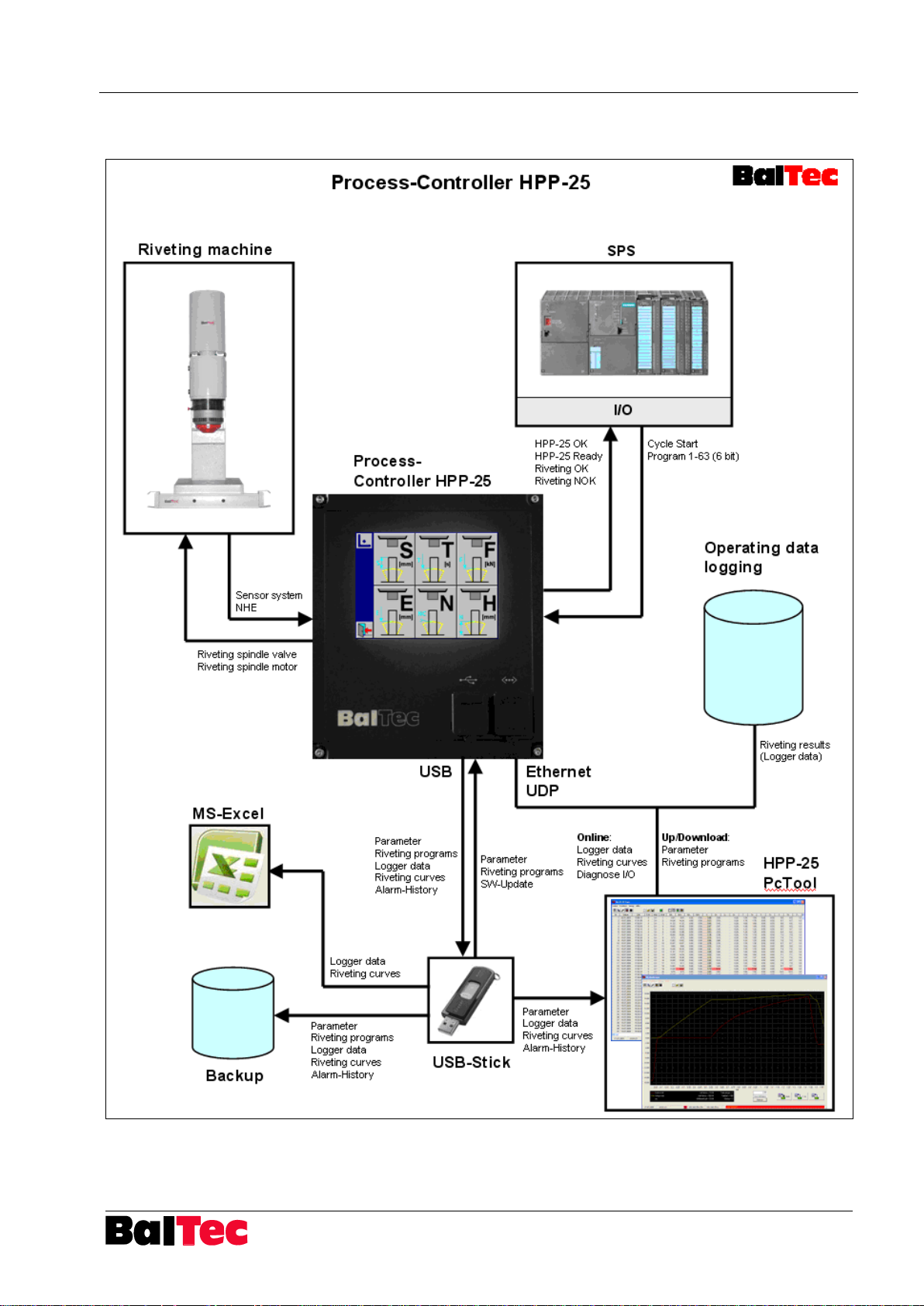
With the software "HPP25-PcTools", which is available as option, a large tool for
diagnosis, data logger, riveting curve display and data backup is available.
Description of software „HPP25-PcTool“ see separate operating instructions.
Page 10
Product description Process-Controller HPP - 25
10
803699.017/ENG
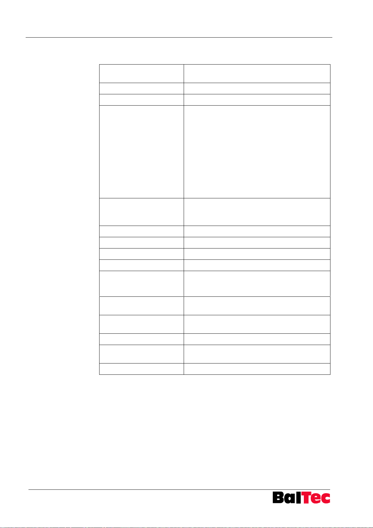
Construction
Sheet metal construction with cast front and rear
panel
Degree of protection
IP53
Cable entry
All connections with plugs
Power supply
Three-phase 50/60Hz
Plugs L1, L2, L3, PE
Connectable wire cross-section max. 2.5mm2
Can be disconnected across all poles with
lockable main switch
Connection voltages:
1x100-120V 1x160-190V
3x160-190V 1x200-240V
3x200-240V 3x320-380V
3x380-500V 3x500-600V
Executed connection voltage see label
Internal feeding voltage
24 VDC +/-2% (at nominal voltage)
For valves and additional consumer load (PLC,
auxiliary relays, lamps, etc.) 4A are available
Fuses
not any, current limiting max. 5A
Control and valves outputs
24 VDC, pnp (+switching), max. per 0.3A
Initiators control inputs
24 VDC, pnp (+switching), 6 mA
General control inputs
24 VDC, pnp (+switching), 10 mA
Potential-free inputs
(instant stop, release,
safety circuit)
24 VDC, min. 10 mA, max. 1A
Processor, operating
system
ARM 9, Windows CE
Display
5.7“ Touch-Screen,
LED backlit
Keyboard
not any, touch operation
Environmental conditions
Operating temperature 0° C - + 50° C
Storage temperature - 10° C - + 70° C
Weight (basic construction)
12 kg
3.2 Technical specifications HPP-25
3.3 Performance Level specifications
In connection with the pneumatic riveting machine the Process-Controller HPP-25
reaches following values:
PL: c
PFHd: 1.33E-6
MTTFd: 85.8 years
Category: 1
Page 11
Process-Controller HPP - 25 Product description
803699.017/ENG
11
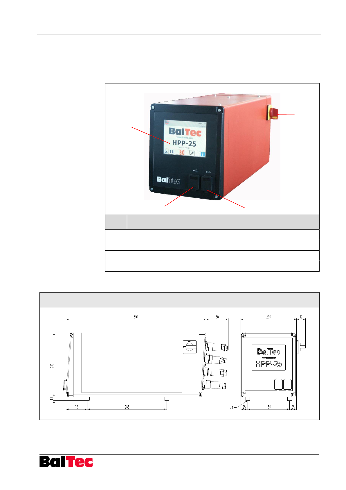
Pos.
Description
1
Main switch
2
Display (Touch-Screen)
3
Ethernet interface
4
USB interface (data backup etc.)
Drawing no. 826337
2 4 1
3
3.4 Details Process-Controller
The Process-Controller HPP-25 is equipped with a touch screen.
All operations, settings and information required for the operation of the riveting
machine are accessible via this touch screen.
3.5 Dimensions drawing
Page 12
Product description Process-Controller HPP - 25
12
803699.017/ENG
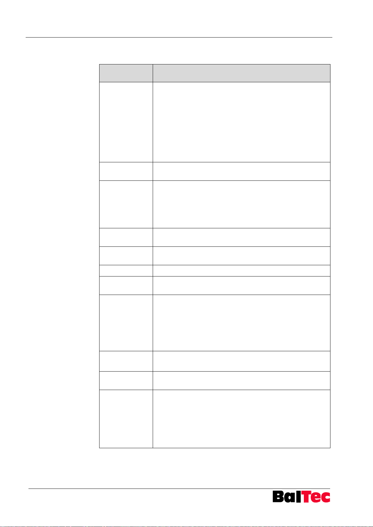
Function
Description
Main riveting
modes
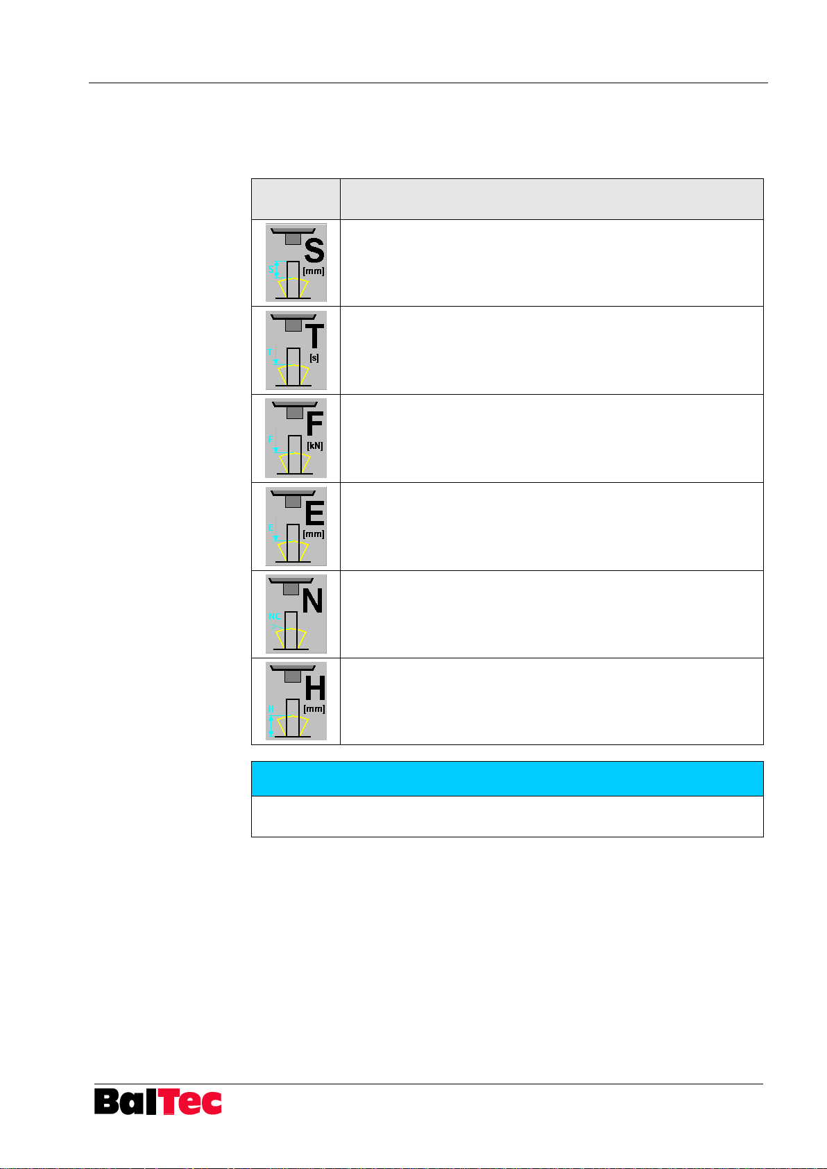
S: Control variable forming path [mm]
T: Control variable forming time [s]
F: Control variable forming force [kN]
E: Control variable spindle path [mm]
N: Control variable external contact
H: Control variable closing head height
Among the above-mentioned main riveting modes more
riveting modes with different control variables are available
(Total 39 riveting modes)
Riveting
programs
63 storable riveting programs (1-63) with additional text (e.g.
article no./description)
Counter
functions
Riveting OK/NOK (resettable)
Preselection counter A/B (resettable)
Riveting total
Operating hours (resettable)
Operating hours total
Integrated
logger function
Integrated data logger for riveting results, readable by USB
interface
Riveting curve
display
Display of riveting curves (path and force curves)
Error history
Memory of error messages with date/timestamp
Diagnosis
Status display of inputs and outputs, as well as path and
force sensors
USB Interface
Export: Data logger
Riveting curves
Parameter
Riveting programs
Alarm-History
Import: Parameter
Riveting programs
Ethernet
Interface
Direct connection at HPP25-PcTool
Riveting results export to PDA (production data acquisition)
PLC Interface
(option)
Interface module for communication with PLC
Analog module
(option)
Analog output for
- proportional pressure control valve (4-20 mA)
- proportional volume flow rate regulating valve (0-700 mA)
Output for
- Rapid speed/working speed valve
Input for
- Initiator BDC
3.6 Functional survey
Page 13
Process-Controller HPP - 25 Product description
803699.017/ENG
13
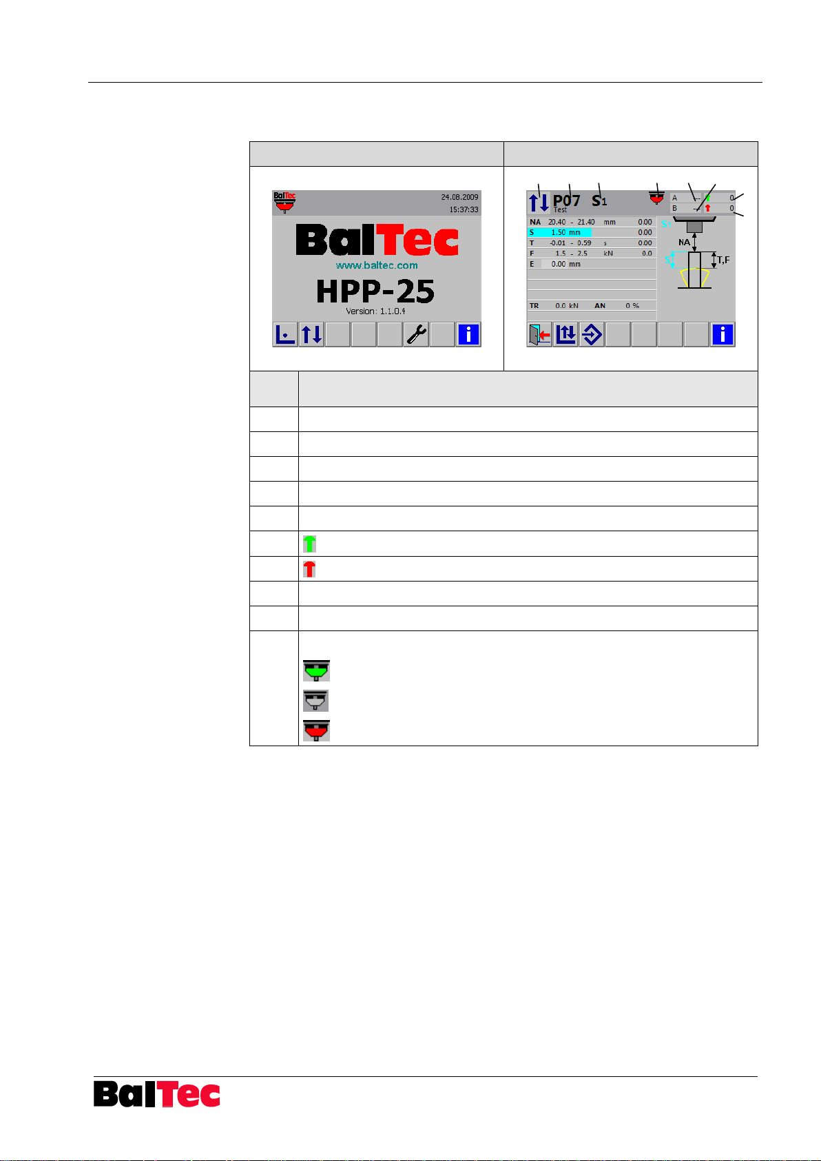
Main menu
Display operating mode Cycle
Pos.
Description
1
Status line (red highlighted if error)
2
Function keys
3
Display of current operating mode
4
Riveting program no. and description
5
Display of current riveting mode
6 Display counter “Riveting OK”
7 Display counter “Riveting NOK”
8
Display counter A
9
Display counter B
10
Display at riveting start
ready for riveting start
no program selected
not ready for riveting start or riveting process active
2 {
1 {
6
7
3 4 5 10 8 9
3.7 Touch-Screen survey
Page 14
Product description Process-Controller HPP - 25
14
803699.017/ENG
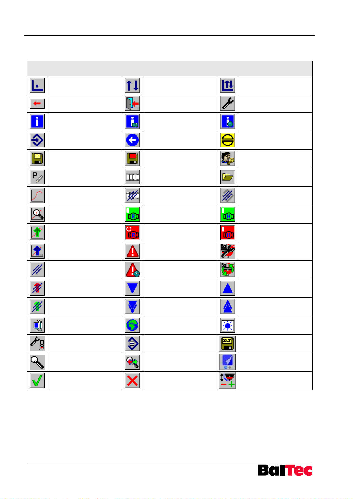
Touch screen keys
Setup operating mode
Cycle operating mode
Correction operating
mode
Delete input
Previous page – to main
menu
Tools
Information
Information counter
Information: riveting,
hours, SW, HW
Select program
Previous page (Setup)
Acknowledge error
Save data (on USB)
Save modified data in the
same riveting program
Enter password
Enter program
identification
Logger data
Load data (from USB)
Riveting curve display
Delete logger data
Delete program
Riveting curve detail view
Riveting motor ON
Motor 2 ON
Select last riveting curve
Riveting motor OFF
Motor 2 OFF
Select second to last
riveting curves
Alarm list (if alarm active)
HPP-25 configuration
Hour counter reset
Alarm History
Execute function (Setup)
NOK counter reset
Line down or next cell
Line up or previous cell
OK counter reset
Scroll page down
Scroll page up
Edit cell
Choose language
Adjust screen contrast
Setup parameter list
Mark several lines
simultaneously
Save logger data as Excel
(on USB)
Diagnosis in- and outputs
sensor system
Change diagnosis window
Change page (2nd page)
Confirm, OK
Cancel, Exit
Correction touch probe
offset / H reference
3.1 Key survey
Page 15
Process-Controller HPP - 25 Product description
803699.017/ENG
15
3.2 Interface survey
Page 16
Commissioning Process-Controller HPP - 25
16
803699.017/ENG
Data for electrical connection
Input voltage
Max. fuse rating
of supply lead
Connection cable
specifications
Standard length
connection cable
see label
16A
3-phase with
ground conductor
5m
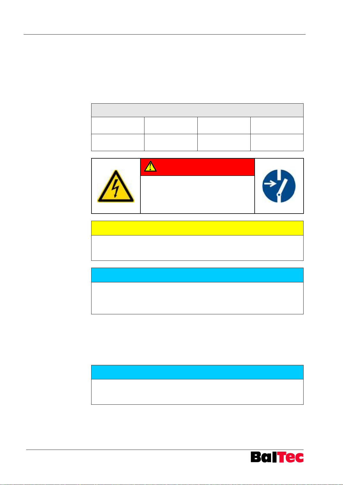
DANGER
Electrical hazard!
Electric shock!
Operations on the control unit are only
permitted with main switch set to “OFF“.
CAUTION
Incorrect input voltage can destroy the electrical and electronic components!
Input voltage must comply with the specification on the label or the front page of
the riveting machine operating instructions.
NOTICE
To avoid interference effects on measuring signal and data lines, the lines from
control unit to riveting machine must be installed separately from high voltage
current and electromagnetic valve cables.
Install no external devices in the control unit if they send out interference signals.
NOTICE
The cable-free plugs on X2, X4 and X6 are dummy plugs with internal bridge.
If these are not plugged in, an error message appears during operation with the
control unit.
4 Commissioning
4.1 Electric supply
The HPP-25 is connected to the mains supply via the connector X20 – see
connecting diagram X20 in the appendix.
Plug and feed cable are included in delivery.
4.2 Connecting the control unit
Connect control unit to riveting unit and their electrical components.
All supplied plugs – with and without cable – must be plugged in the corresponding
plug socket on the control unit.
Page 17
Process-Controller HPP - 25 Operation
803699.017/ENG
17
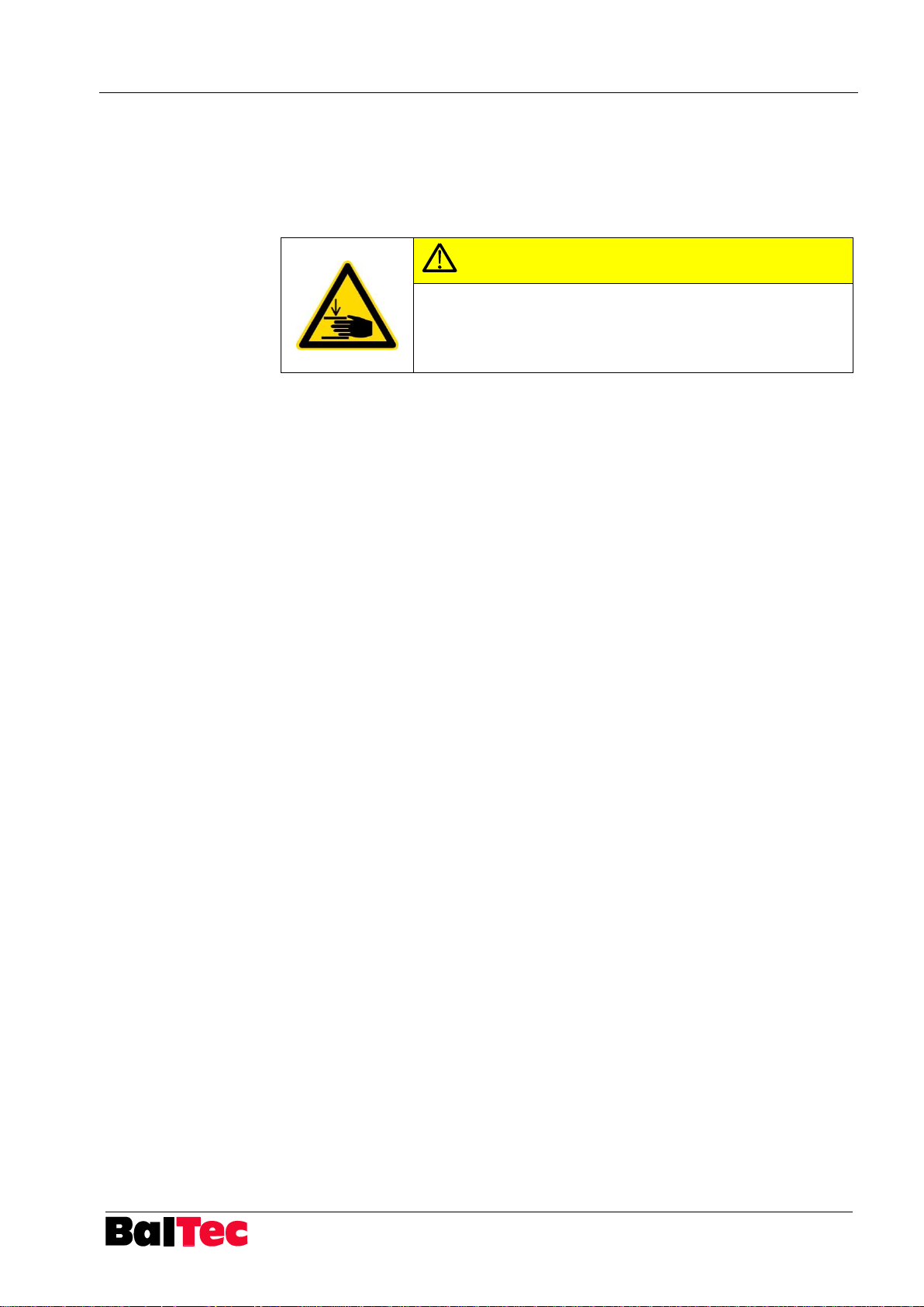
CAUTION
Danger of hand injuries!
After a long standstill period, the riveting spindle can sink. By
switching-on the Process-Controller the riveting spindle runs
automatically in the upper starting position!
5 Operation
5.1 Switching-on the Process-Controller
The Process-Controller is switched on using the main switch (right side, rear).
Start-up
The processor runs through the initialization process and tests the safety
conditions. If the processor is working correctly and all safety conditions are met,
then the machine is ready for operation.
The startup process lasts approx. 5 seconds. During the start-up the screen
remains dark.
Machine ready for operation
The main menu appears on the display. It is possible to work, make settings and
obtain information in the appropriate operating mode.
Machine not ready for operation
If the machine is not ready for operation, the status line is red highlighted an error
message is displayed.
5.2 Switching-off the Process-Controller
The Process-Controller is switched off using the main switch (right side, rear).
The internal power supply ensures that all counter readings are saved and the
operating system is shut down correctly.
Page 18
Operation Process-Controller HPP - 25
18
803699.017/ENG
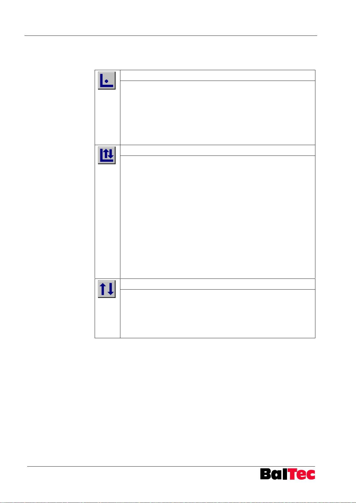
Setup operating mode
This operating mode serves for setup a new program in a new riveting
mode (S, T, F, E, N, H).
The riveting process lasts as long as the start signal is active – i.e. as
long as two-hand operating unit or foot switch are activated.
The process data during this period will be automatically registered and
displayed after the setup riveting.
The Process-Controller then changes automatically in Correction
operating mode.
Correction operating mode
The access to Correction operating mode happens automatically after
a setup riveting or if in the Cycle operation mode the key Correction
operating mode is selected.
The requirement for the control variable can be changed just like the
limits for the other process variables.
The riveting process is controlled according the control variable and
the evaluated variables are recalculated.
Activation of riveting process according parameter 85 adjustment
(continuous signal, pulse signal or bridging)
Note:
After following modification a correction riveting may be necessary:
- Modification of any control variable or other process variables
- Modification of operating pressure or riveting position
- Change of form tool
A correction riveting must always be executed with a new rivet.
Cycle operating mode
In Cycle operating mode the riveting process is stopped when reaching
the nominal value of the reference input variable.
The nominal and the actual values are displayed and are evaluated
according to riveting program.
If the control variable or one of the process variables is out of tolerance
the riveting is evaluated as NOK.
5.3 Operating modes
The following 3 operating modes are distinguished in the HPP-25:
Page 19
Process-Controller HPP - 25 Operation
803699.017/ENG
19
Riveting
mode
Description
Control with reference input variable riveting path (forming path).
There are several riveting modes S with various monitored process
variables available.
Control with reference input variable riveting time (forming time).
There are several riveting modes T with various monitored process
variables available.
Control with reference input variable riveting force.
There are several riveting modes F with various monitored process
variables available.
Control with reference input variable spindle path.
There are several riveting modes E with various monitored process
variables available.
Control with reference input variable external contact.
There are several riveting modes N with various monitored process
variables available.
Control with reference input variable closing head height.
There are several riveting modes h with various monitored process
variables available.
NOTICE
With the aid of the filter (setup parameter 81) the number of displayed riveting
modes can be limited.
5.4 Riveting modes survey
Depending on the hardware defined in the setup and connected, the required
riveting mode for a setup riveting can be selected.
Page 20
Operation Process-Controller HPP - 25
20
803699.017/ENG
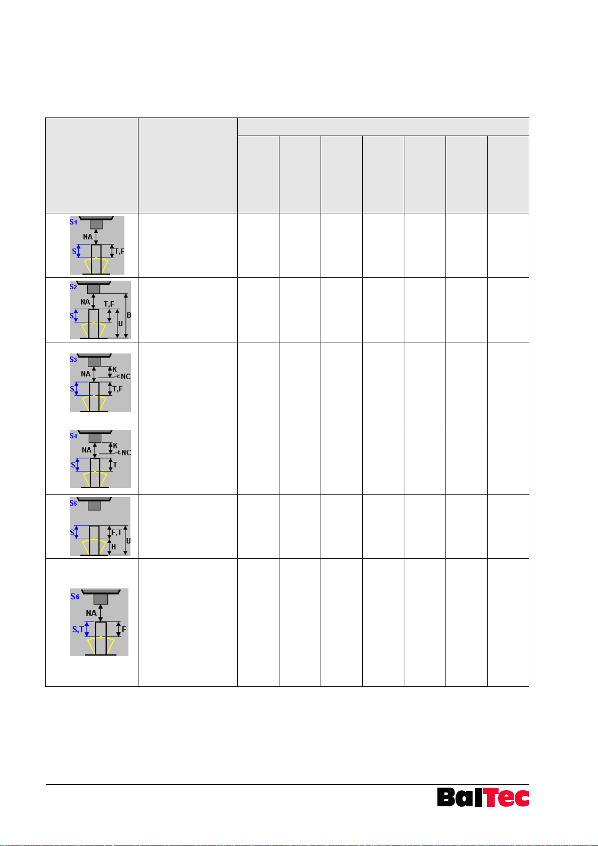
Riveting mode
Description
necessary hardware
Path sensor at
riveting
spindle (X13)
Path sensor at
NHE (X13)
Pressure
sensors
(X11,12)
Projection
measurement
NHE (X14)
NHE riveting
end (X14)
Switch BDC
(X5)
External NA
(X14)
S1
S controlled after
detection of NA
NA, T and F
monitored
X X
S2
S controlled after
detection of NA
NA, B, U, T and F
monitored
X X X
S3
S controlled after
detection of NA
NA detection by
external signal
NA, T and F
monitored
X X X
S4
S controlled after
detection of NA
NA detection by
external signal
NA and T monitored
X X
S5
S controlled after
detection of NA
U, F, T and H
monitored
X X
S6
S or T controlled
after detection of NA
F (S or T) monitored
The first control
value that is
reached, will finish
the cycle, the
second control value
will be used for
evaluation
X X
5.4.1 Riveting mode S
The following riveting modes with control variable S (riveting path) are available:
Page 21
Process-Controller HPP - 25 Operation
803699.017/ENG
21
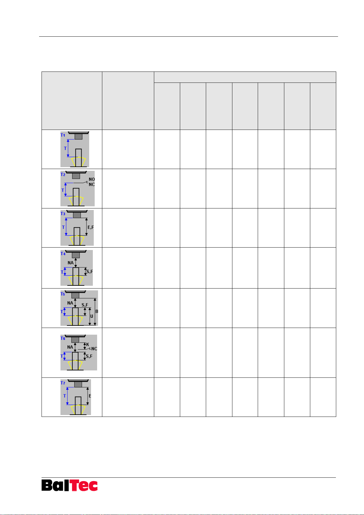
Riveting mode
Description
necessary hardware
Path sensor at
riveting
spindle (X13)
Path sensor at
NHE (X13)
Pressure
sensors
(X11,12)
Projection
measurement
NHE (X14)
NHE riveting
end (X14)
Switch BDC
(X5)
External NA
(X14)
T1
T controlled from
TDC
No additional
values monitored
T2
T controlled from
BDC
No additional
values monitored
X
T3
T controlled from
TDC
E and F
monitored
X X
T4
T controlled after
detection of NA
(forming time)
NA, S and F
monitored
X X
T5
T controlled after
detection of NA
NA, U, S, F and
B monitored
X X X
T6
T controlled after
detection of NA
NA detection by
external signal
NA, K, S and F
monitored
X X X
T7
T controlled from
TDC
E monitored
X
5.4.2 Riveting mode T
The following riveting modes with control variable T (riveting time) are available:
Page 22
Operation Process-Controller HPP - 25
22
803699.017/ENG
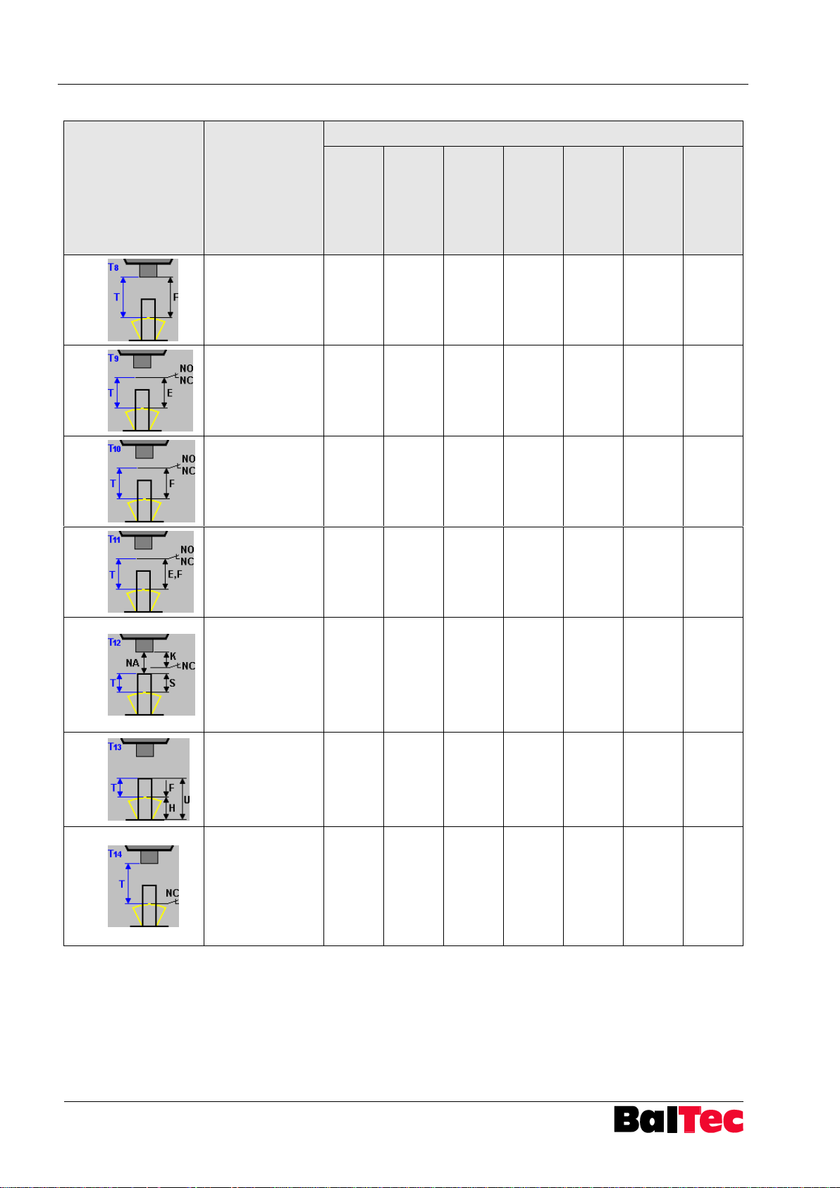
Riveting mode
Description
necessary hardware
Path sensor at
riveting
spindle (X13)
Path sensor at
NHE (X13)
Pressure
sensors
(X11,12)
Projection
measurement
NHE (X14)
NHE riveting
end (X14)
Switch BDC
(X5)
External NA
(X14)
T8
T controlled from
TDC
F monitored
X
T9
T controlled from
BDC
E monitored
X X
T10
T controlled from
BDC
F monitored
X X
T11
T controlled from
BDC
E and F
monitored
X X X
T12
T controlled after
detection of NA
NA detection by
external signal
NA and S
monitored
X X
T13
T controlled after
detection of NA
with NHE
U, H and F
monitored
X X
T14
T controlled from
TDC
or
until contact NHE
No additional
values monitored
X
Page 23
Process-Controller HPP - 25 Operation
803699.017/ENG
23
Riveting mode
Description
necessary hardware
Path sensor at
riveting
spindle (X13)
Path sensor at
NHE (X13)
Pressure
sensors
(X11,12)
Projection
measurement
NHE (X14)
NHE riveting
end (X14)
Switch BDC
(X5)
External NA
(X14)
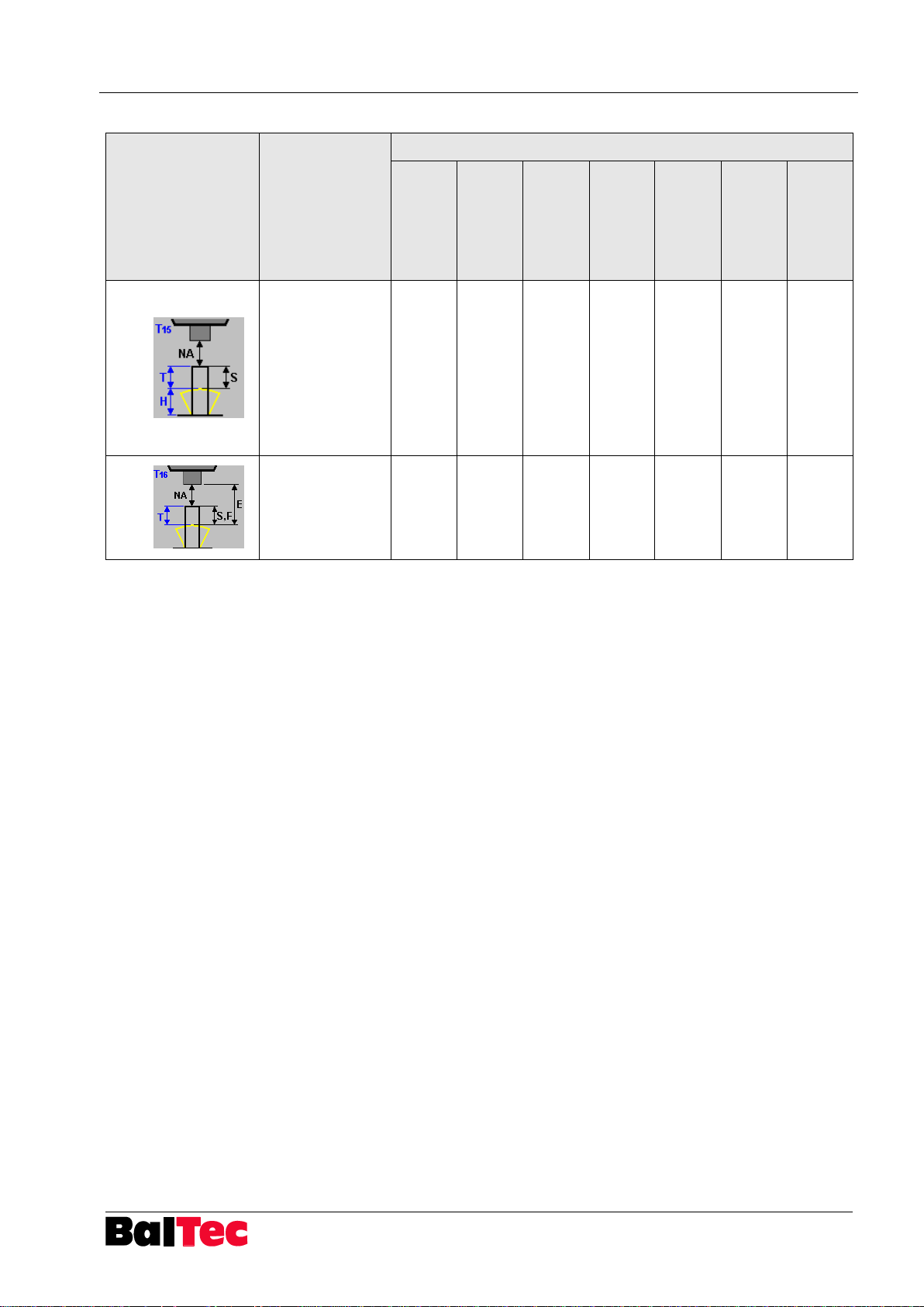
T15
T or H controlled
The first control
value that is
reached, will
finish the cycle,
the second
control value will
be used for
evaluation
X X
T16
T controlled after
detection of NA
(forming time)
NA, S, F and E
monitored
X X
Page 24
Operation Process-Controller HPP - 25
24
803699.017/ENG
Riveting mode
Description
necessary hardware
Path sensor at
riveting
spindle (X13)
Path sensor at
NHE (X13)
Pressure
sensors
(X11,12)
Projection
measurement
NHE (X14)
NHE riveting
end (X14)
Switch BDC
(X5)
External NA
(X14)
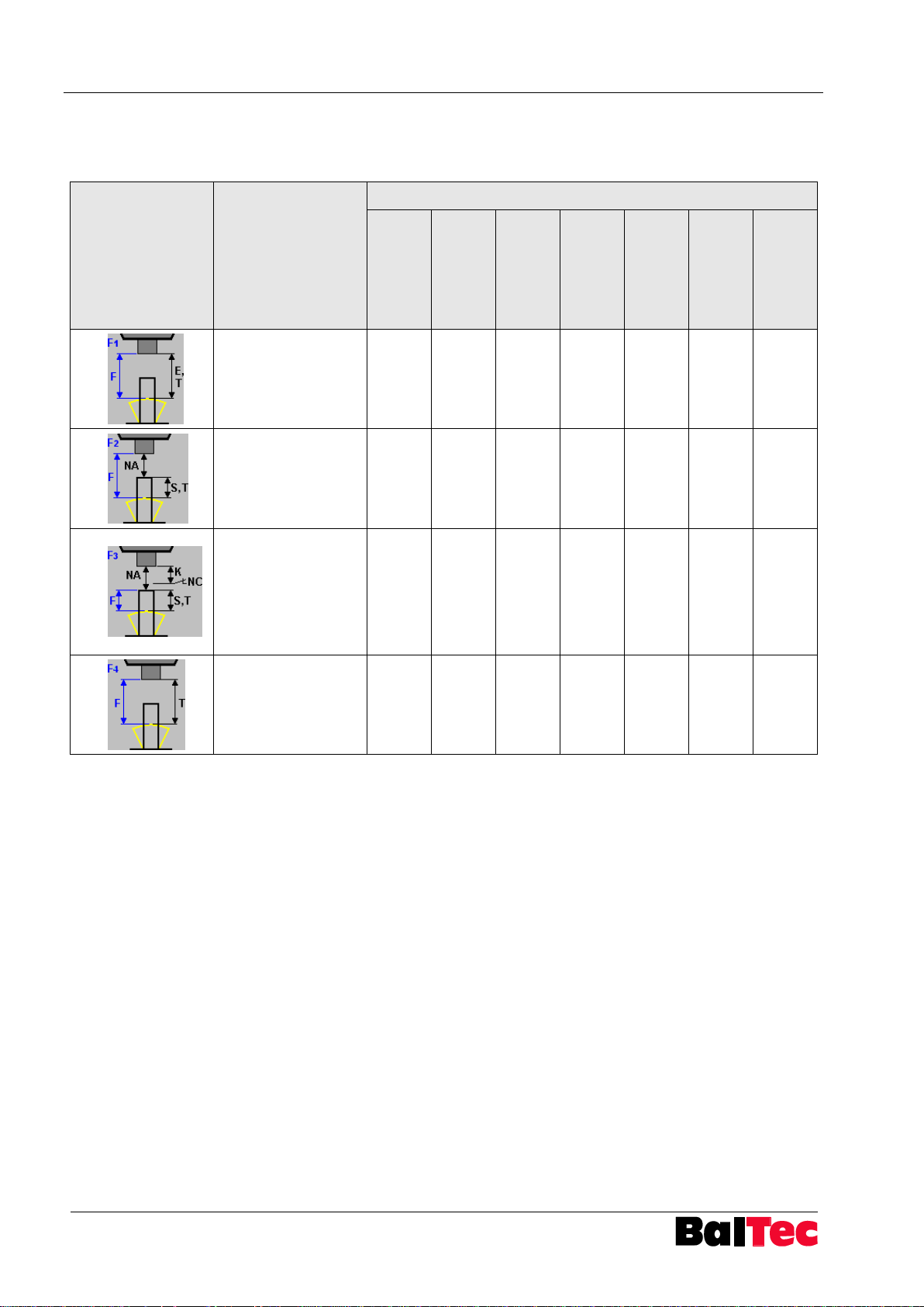
F1
F controlled from
TDC
E and T monitored
X X
F2
F controlled after
detection of NA
NA, S and T
monitored
X X
F3
F controlled after
detection of NA
NA detection by
external signal
NA, S and T
monitored
X X X
F4
F controlled from
TDC
T monitored
X
5.4.3 Riveting mode F
The following riveting modes with control variable F (riveting force) are available:
Page 25
Process-Controller HPP - 25 Operation
803699.017/ENG
25
Riveting mode
Description
necessary hardware
Path sensor at
riveting
spindle (X13)
Path sensor at
NHE (X13)
Pressure
sensors
(X11,12)
Projection
measurement
NHE (X14)
NHE riveting
end (X14)
Switch BDC
(X5)
External NA
(X14)
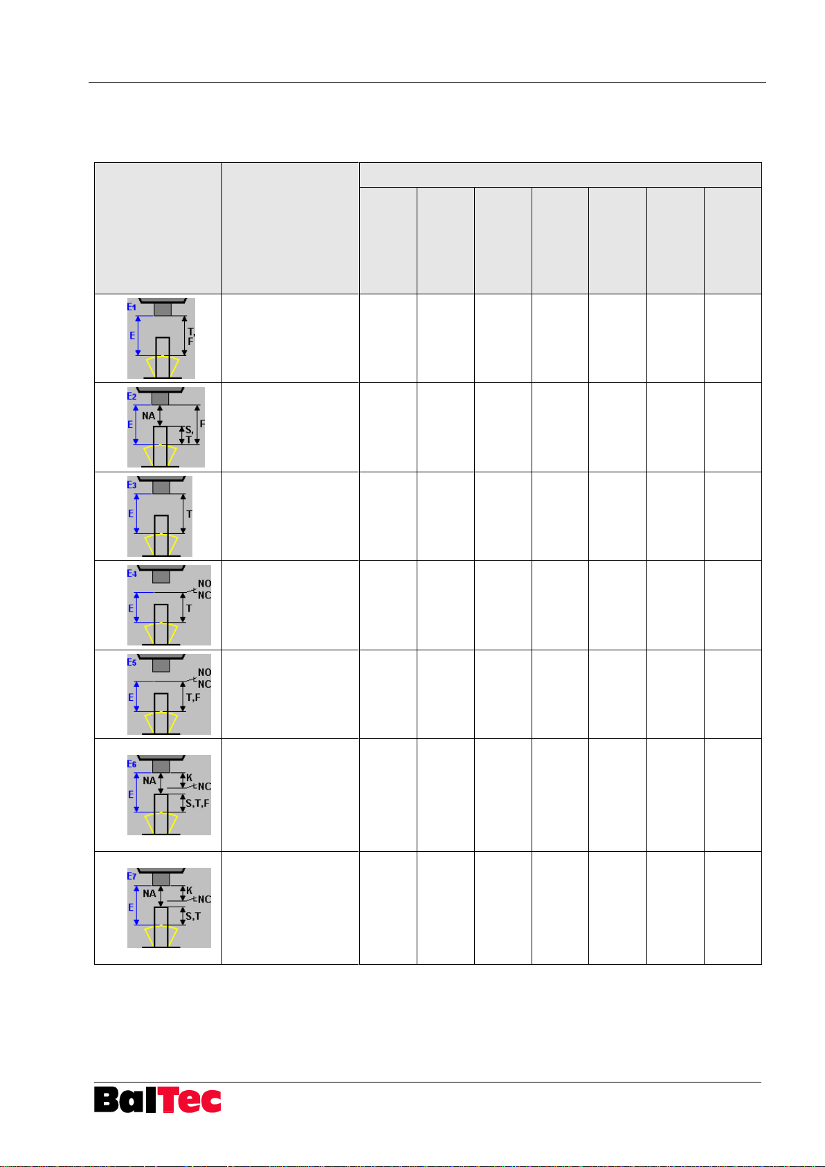
E1
E controlled from
TDC
T and F monitored
X X
E2
E controlled from
TDC
NA, S, T and F
monitored
X X
E3
E controlled from
TDC
T monitored
X
E4
E controlled from
BDC
T monitored
X X
E5
E controlled from
BDC
T and F monitored
X X X
E6
E controlled from
TDC
NA detection by
external signal
NA, S, T and F
monitored
X X X
E7
E controlled from
TDC
NA detection by
external signal
NA, S and T
monitored
X X
5.4.4 Riveting mode E
The following riveting modes with control variable E (spindle path) are available:
Page 26
Operation Process-Controller HPP - 25
26
803699.017/ENG
Riveting mode
Description
necessary hardware
Path sensor at
riveting
spindle (X13)
Path sensor at
NHE (X13)
Pressure
sensors
(X11,12)
Projection
measurement
NHE (X14)
NHE riveting
end (X14)
Switch BDC
(X5)
External NA
(X14)
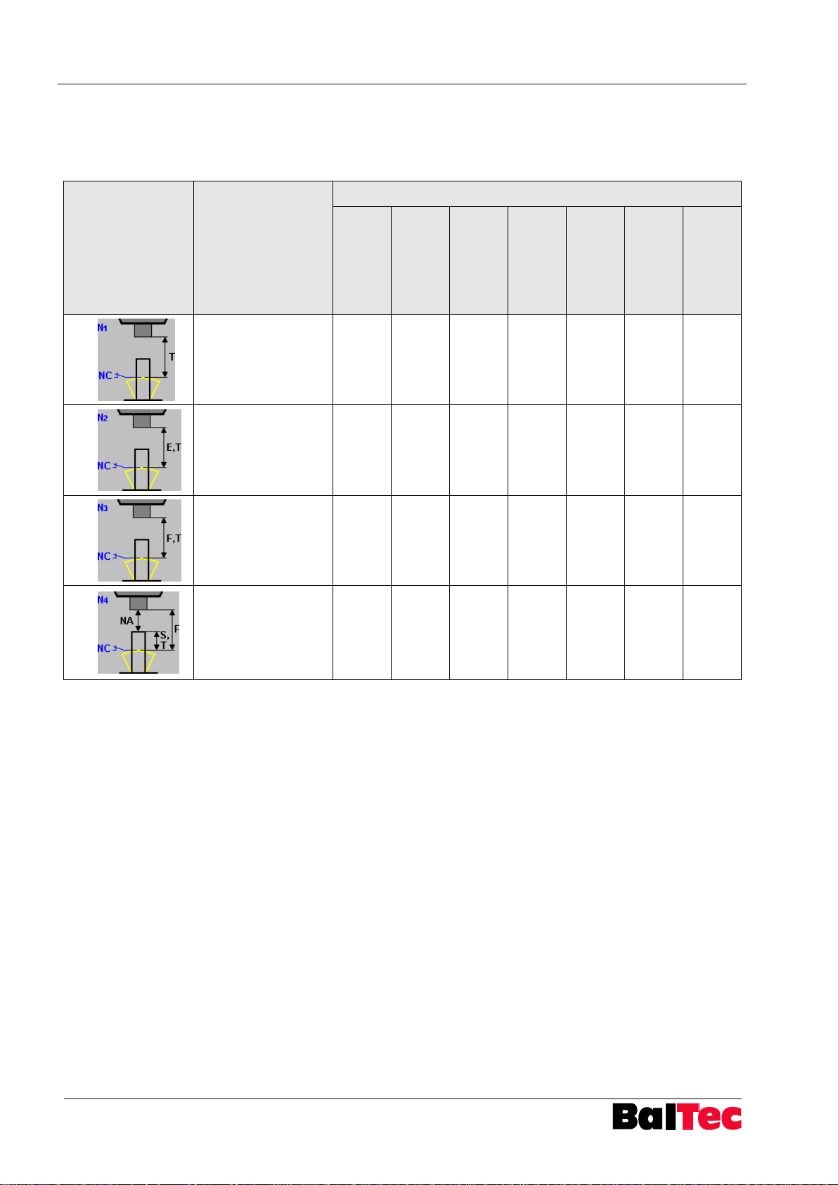
N1
Riveting process
controlled until
external signal
T monitored
X
N2
Riveting process
controlled until
external signal
T and E monitored
X X
N3
Riveting process
controlled until
external signal
T and F monitored
X X
N4
Riveting process
controlled until
external signal
NA, S, T and F
monitored
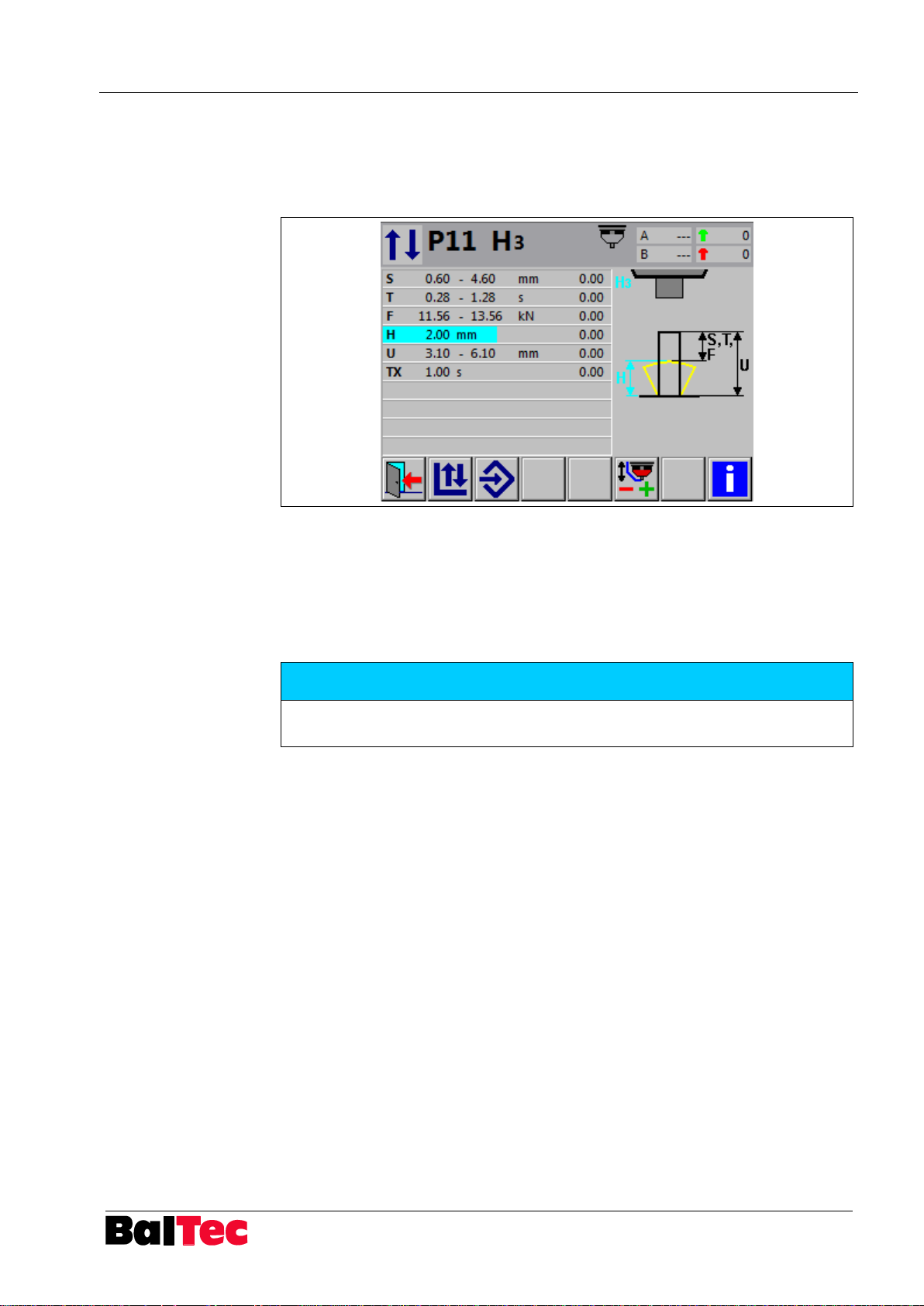
X X X
5.4.5 Riveting mode N
The following riveting modes with control variable N (external contact) are
available:
Page 27
Process-Controller HPP - 25 Operation
803699.017/ENG
27
Riveting mode
Description
necessary hardware
Path sensor at
riveting
spindle (X13)
Path sensor at
NHE (X13)
Pressure
sensors
(X11,12)
Projection
measurement
NHE (X14)
NHE riveting
end (X14)
Switch BDC
(X5)
External NA
(X14)
H1
H controlled
T and F monitored
X X
H2
H controlled
T and F monitored
X X
H3
H controlled
U, S, T and F
monitored
X X
H4
H controlled
T monitored
X
H5
H controlled
T monitored
X
H6
H controlled
NA, S, T, F
monitored
like mode H1, but
additionally with NA
and S evaluation
X X
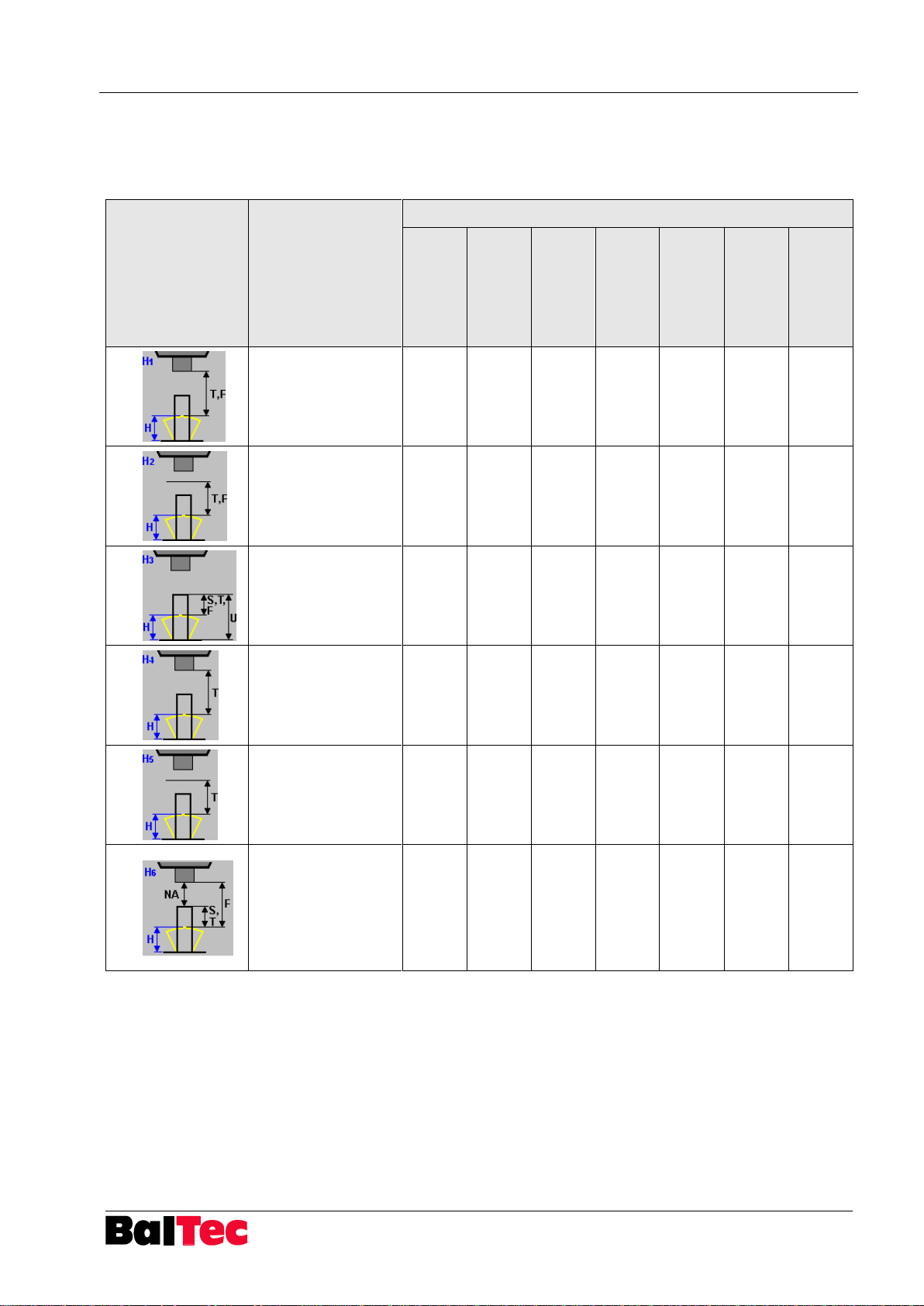
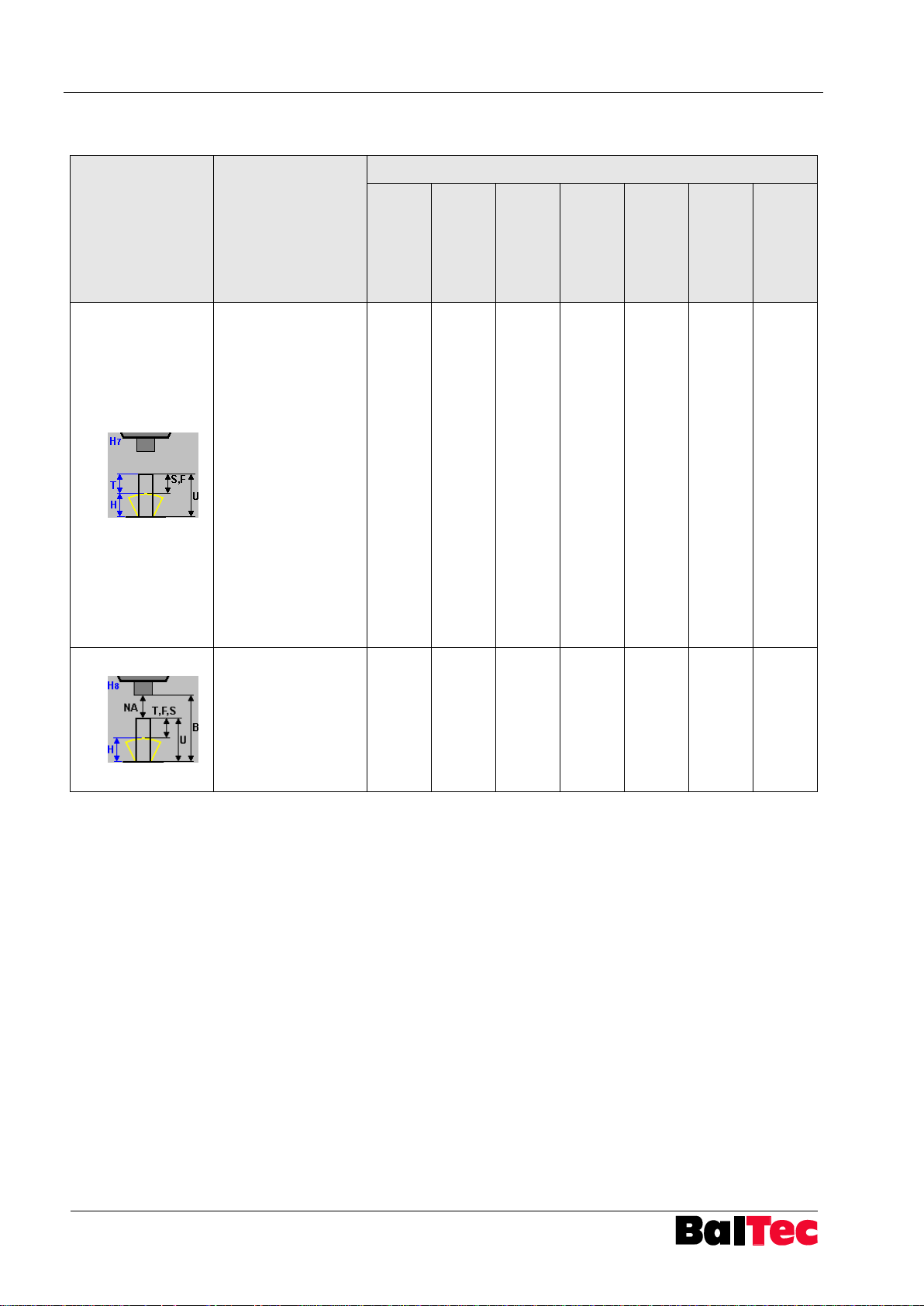
5.4.6 Riveting mode H
The following riveting modes with control variable H (closing head height) are
available:
Page 28
Operation Process-Controller HPP - 25
28
803699.017/ENG
Riveting mode
Description
necessary hardware
Path sensor at
riveting
spindle (X13)
Path sensor at
NHE (X13)
Pressure
sensors
(X11,12)
Projection
measurement
NHE (X14)
NHE riveting
end (X14)
Switch BDC
(X5)
External NA
(X14)
H7
Riveting mode with 2
control variables H
and T
AND-operation of
the two control
variables – both
variables must be
fulfilled
The first variable that
is reached will be
evaluated with the
tolerance in the
program
The second variable,
which terminates the
riveting cycle, is
evaluated by
parameter
X X
H8
H controlled after
detection of NA
NA, B, U, T, F and S
monitored
NHE-U for projection
measurement
required
X X X
Page 29
Process-Controller HPP - 25 Operation
803699.017/ENG
29
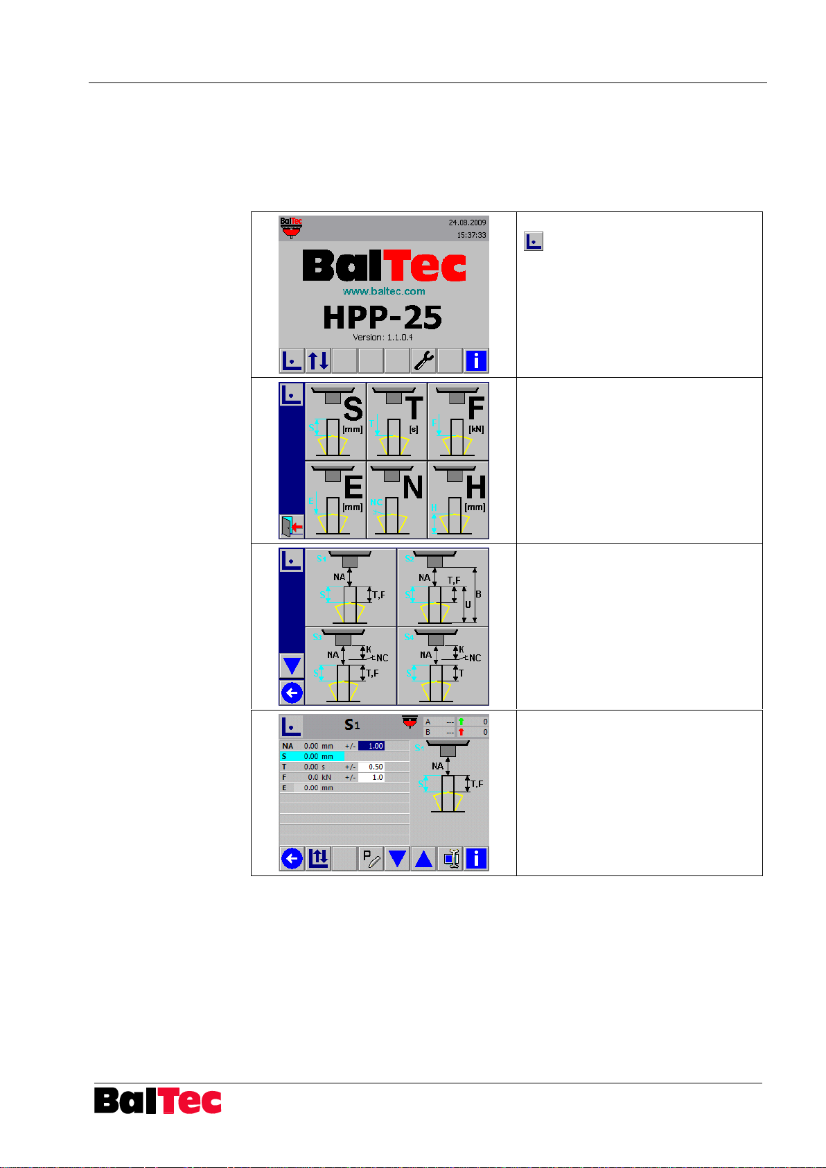
Select key “Setup operating mode“
in main menu
Select riveting mode S
Select riveting mode S1
Displayed riveting modes depends
from the defined HW in setup table
and the filter selection
Actuate a setup riveting (Two-hand
operating unit, foot switch)
The riveting procedure is active as
long as the command device is
pressed
Then, the reached values are
displayed
5.5 Creation of a riveting program (Standard)
The following description corresponds to the creation of a riveting program in the
riveting mode S1.
5.5.1 Setup operating mode
Page 30
Operation Process-Controller HPP - 25
30
803699.017/ENG
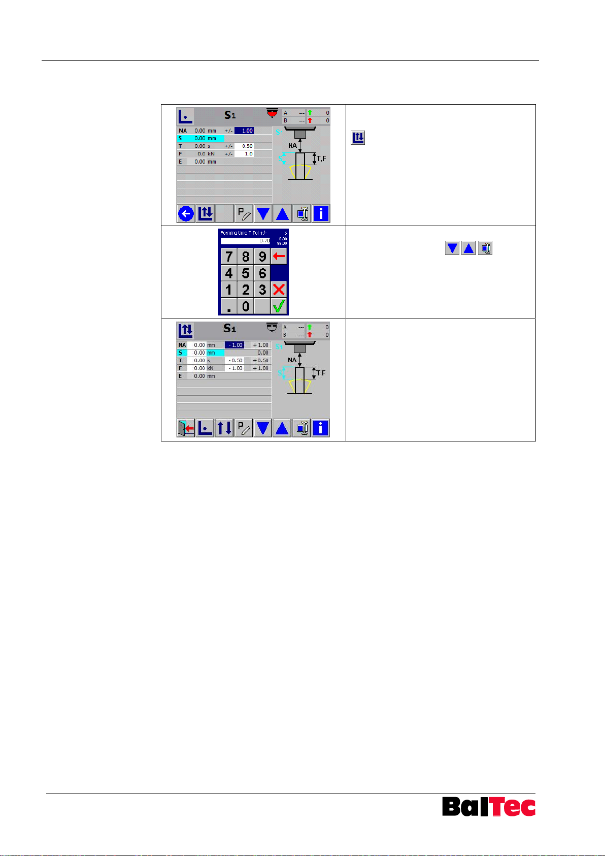
After the execution of setup riveting
select key “Correction operating mode“
If necessary adjust control variable and
tolerances with keys and
confirm with OK
Actuate a new riveting process
Riveting process is stopped when
reaching the control variable and all
values are read anew
5.5.2 Correction operating mode
Page 31
Process-Controller HPP - 25 Operation
803699.017/ENG
31
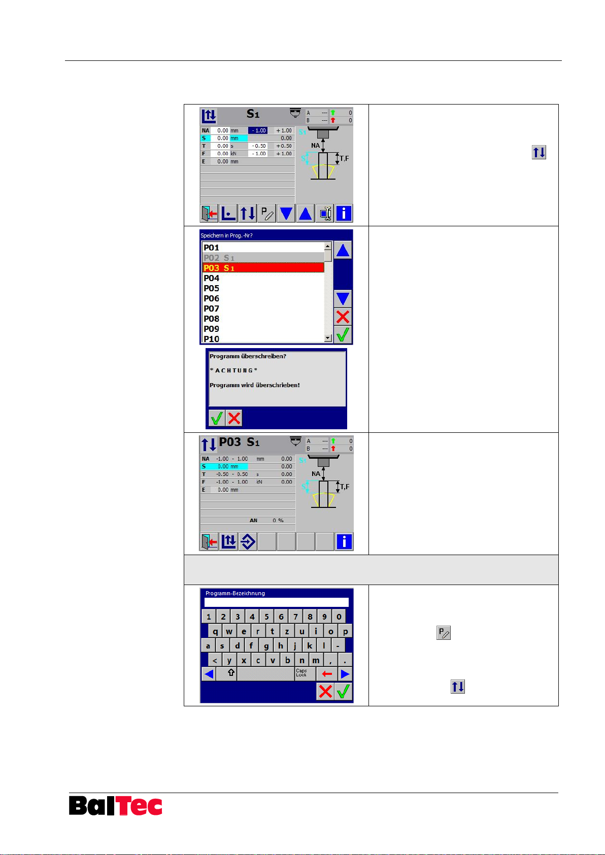
If the riveting result corresponds to the
desired requirements, the riveting
program can be saved.
Select key “Cycle operating mode“
Program list appears.
a) select free program number and
confirm with OK
b) select overwriting program and
confirm with OK
Program returns in Cycle operating
mode
Enter program description (possible only in Correction and Setup
operating mode)
In addition to program number a
program name can be assigned
Select key “Enter program
identification” , enter name (max. 30
signs) and confirm with OK
The riveting program is therefore
created and can be called in the “Cycle
operating mode”
5.5.3 Save riveting program
Page 32
Operation Process-Controller HPP - 25
32
803699.017/ENG
NOTICE
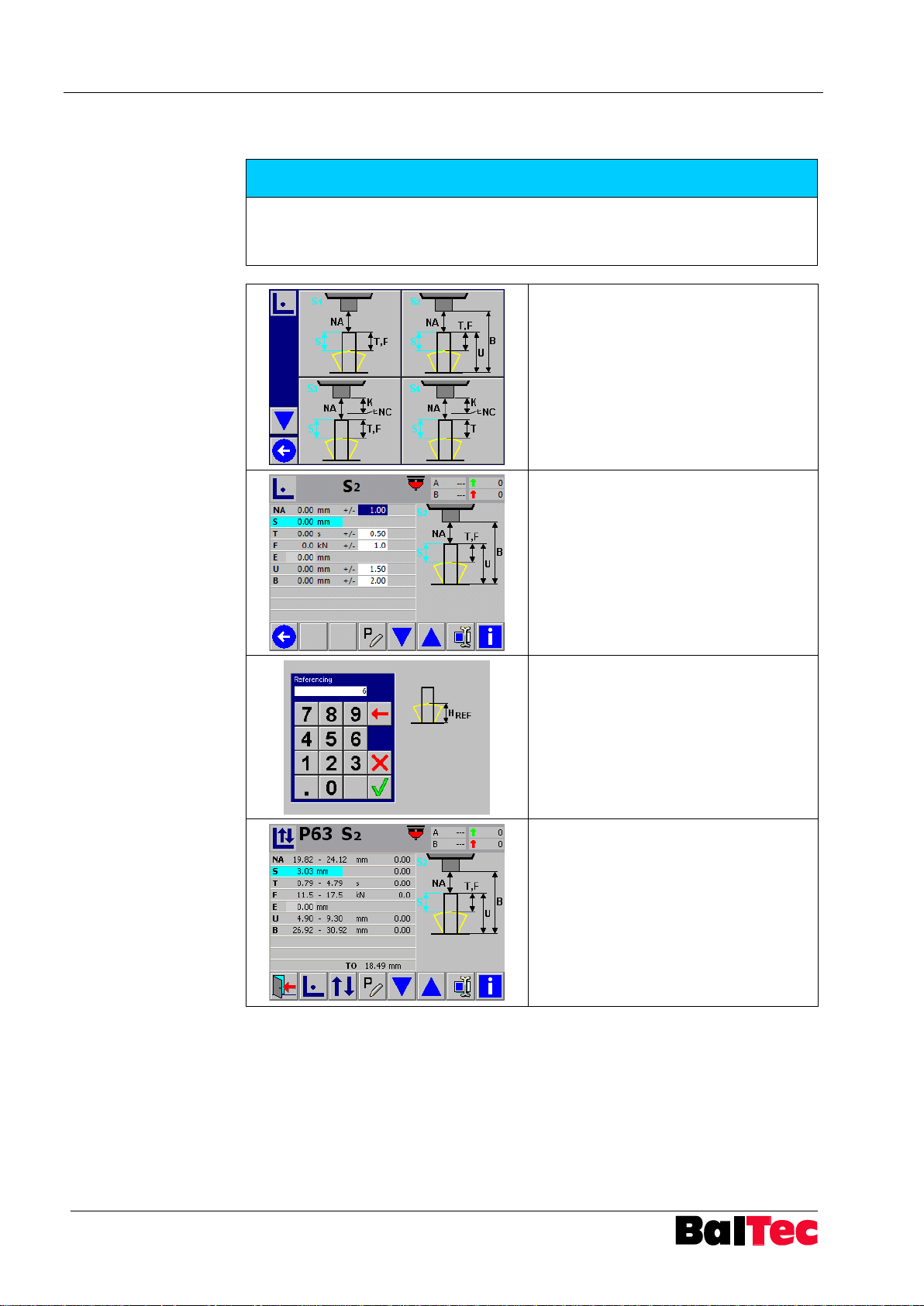
For riveting modes with projection measurement the projection measuring device
NHE is required.
Activation function NHE – Parameter 75 = 2
Select riveting mode S2
Actuate a setup riveting (Two-hand
operating unit, foot switch)
The riveting procedure is active as long
as the command device is pressed
Enter reference dimension
The closing head height serves as
reference at just riveted piece
After confirmation of the reference
dimension, the Process-Controller
jumps directly to Correction operating
mode
Indicative the value TO is displayed
This is the touch probe offset value =
Dimension between workpiece base
and touch probe (touch probe switching
point)
5.6 Creation of riveting program with projection measurement (riveting modes S2, T5, H8)
Page 33
Process-Controller HPP - 25 Operation
803699.017/ENG
33
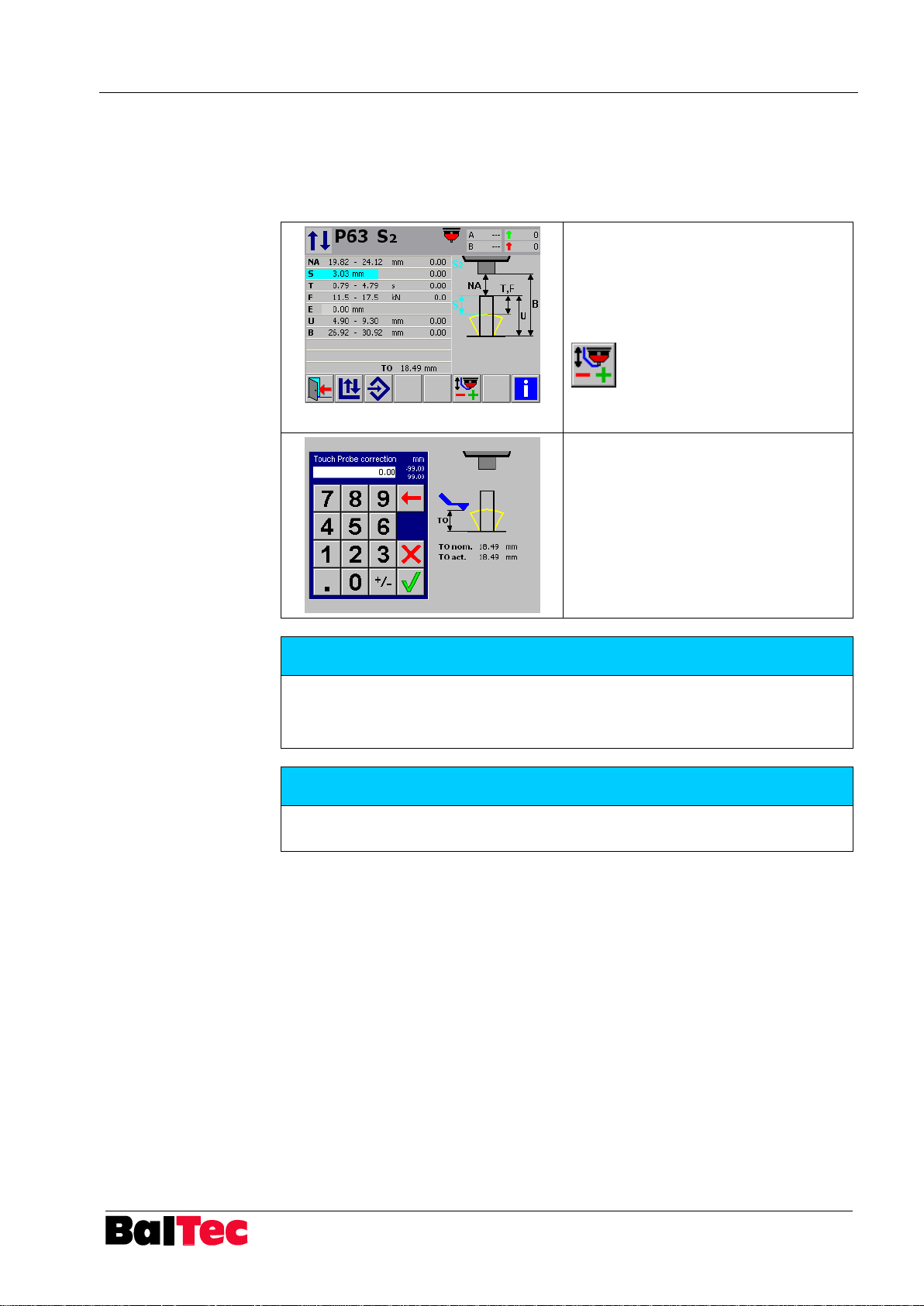
Actuate a riveting with new touch probe
configuration in Cycle operating mode –
depending on the tolerances the
riveting can be NOK.
If parameter 82 is active following key
appears:
Select key to execute correction
function.
The Process-Controller measures the
new TO (TO actual value in adjacent
figure).
If there is a difference between new TO
value and saved TO value the HPP-25
calculates the necessary correction.
The correction can be accepted by
pressing confirm key.
NOTICE
Activate parameter 82 (Touch probe offset correction mode):
1 = correction only for current riveting program
2 = correction for all riveting programs
NOTICE
Use only parameter 82 = 1, if you have programs with projection measurement
(S2, T5) and H-modes.
5.6.1 Adjust touch probe offset
If the touch probe or the My-Com switch in NHE is changed, the touch probe offset
is no longer correct (value TO).
To correct these values without a new setup riveting following function is available:
Page 34
Operation Process-Controller HPP - 25
34
803699.017/ENG
NOTICE
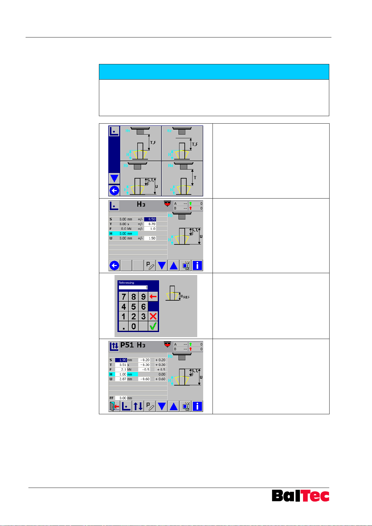
For riveting modes H2, H3 and H5 a projection measuring device with integrated
path measurement is required.
Set parameter 33 = 1
Negative values for H are possible from SW version 1.3.0.1!
Select riveting mode H
Actuate a setup riveting (Two-hand
operating unit, foot switch)
The riveting procedure is active as long
as the command device is pressed
Enter reference dimension
The closing head height serves as
reference at just riveted piece
After confirmation of the reference
dimension, the Process-Controller
jumps directly to Correction operating
mode
5.7 Creation of riveting program (riveting mode H)
Page 35
Process-Controller HPP - 25 Operation
803699.017/ENG
35
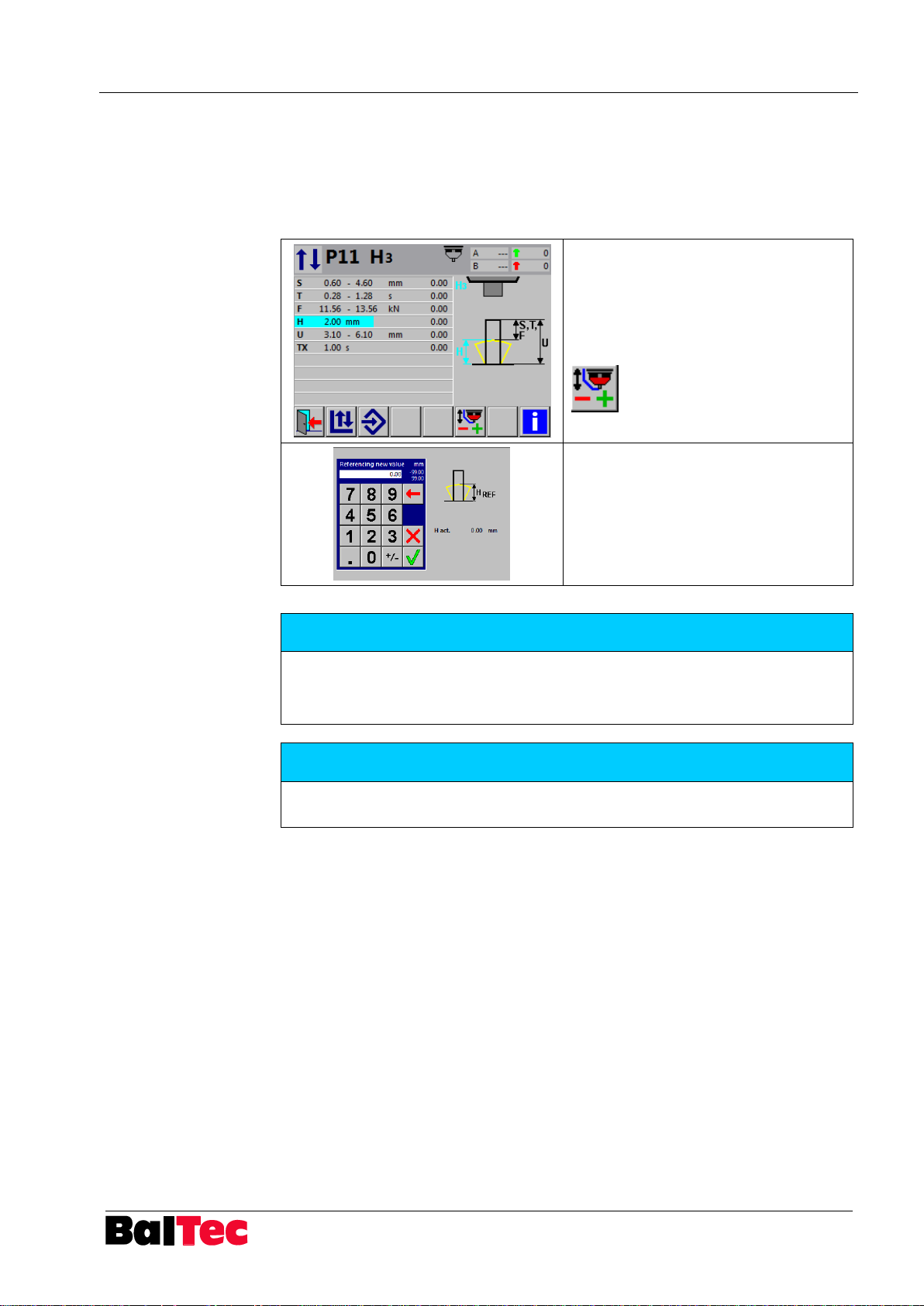
Make a riveting in cycle operation
mode.
Measure the closing head height and
compare with H value on display.
If there is a difference, press following
key:
Window “Referencing new value”
appears
Enter measured actual H value
Confirm with OK
NOTICE
Activate parameter 82 (Touch probe offset correction mode):
1 = correction only for current riveting program
2 = correction for all riveting programs
NOTICE
Use only parameter 82=1, if you have programs with projection measurement
(S2, T5) and H-mode.
5.7.1 Reference height correction in H-mode
This function allows the adjustment of the displayed actual H value to the
measured value of the closing head height on workpiece. The input option for the
reference height correction is indicated in the cycle operation mode.
Procedure:
Page 36
Operation Process-Controller HPP - 25
36
803699.017/ENG
NOTICE
Set parameter 75 = 3
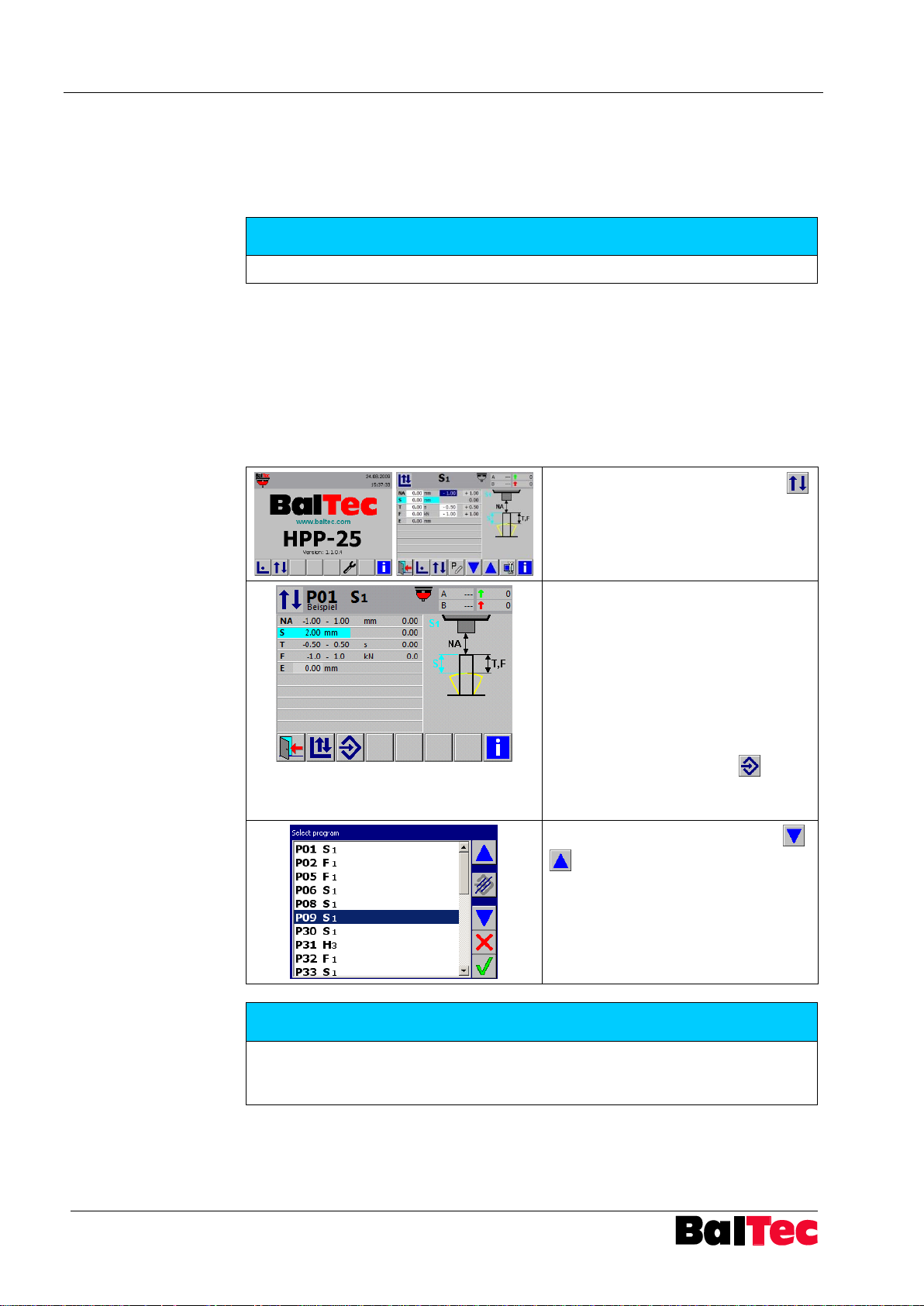
Select key “Cycle operating mode“
in main menu or in Correction
operating mode
When switching over from main
menu to Cycle operating mode, the
last program, in which has been
worked, is displayed
When switching over from Correction
operating mode to Cycle operating
mode, the current created or
changed riveting program is
displayed
With key „“Select program“
another existing program can be
selected
Select desired program with keys
and confirm with key OK
NOTICE
Riveting programs with red text indicate that the programs have been created
with another HW configuration and are not functional with the currently existing
HW.
5.8 Creation of riveting program with external NA detection
In the riveting modes S3, S4, T6, T12, F3, E6 and E7 the rivet front end (NA) is
detected by an external signal on X14 (e.g. laser sensor).
The sensor compared to form tool has thereby leading (advance). This leading is
entered as offset value in parameter 32.
5.9 Working with existing riveting program
5.9.1 Cycle operating mode
In Cycle operating mode existing riveting programs can be selected.
Procedure:
Riveting in Cycle operating mode are evaluated as follows:
OK values are green highlighted
NOK values are red highlighted
Page 37
Process-Controller HPP - 25 Operation
803699.017/ENG
37
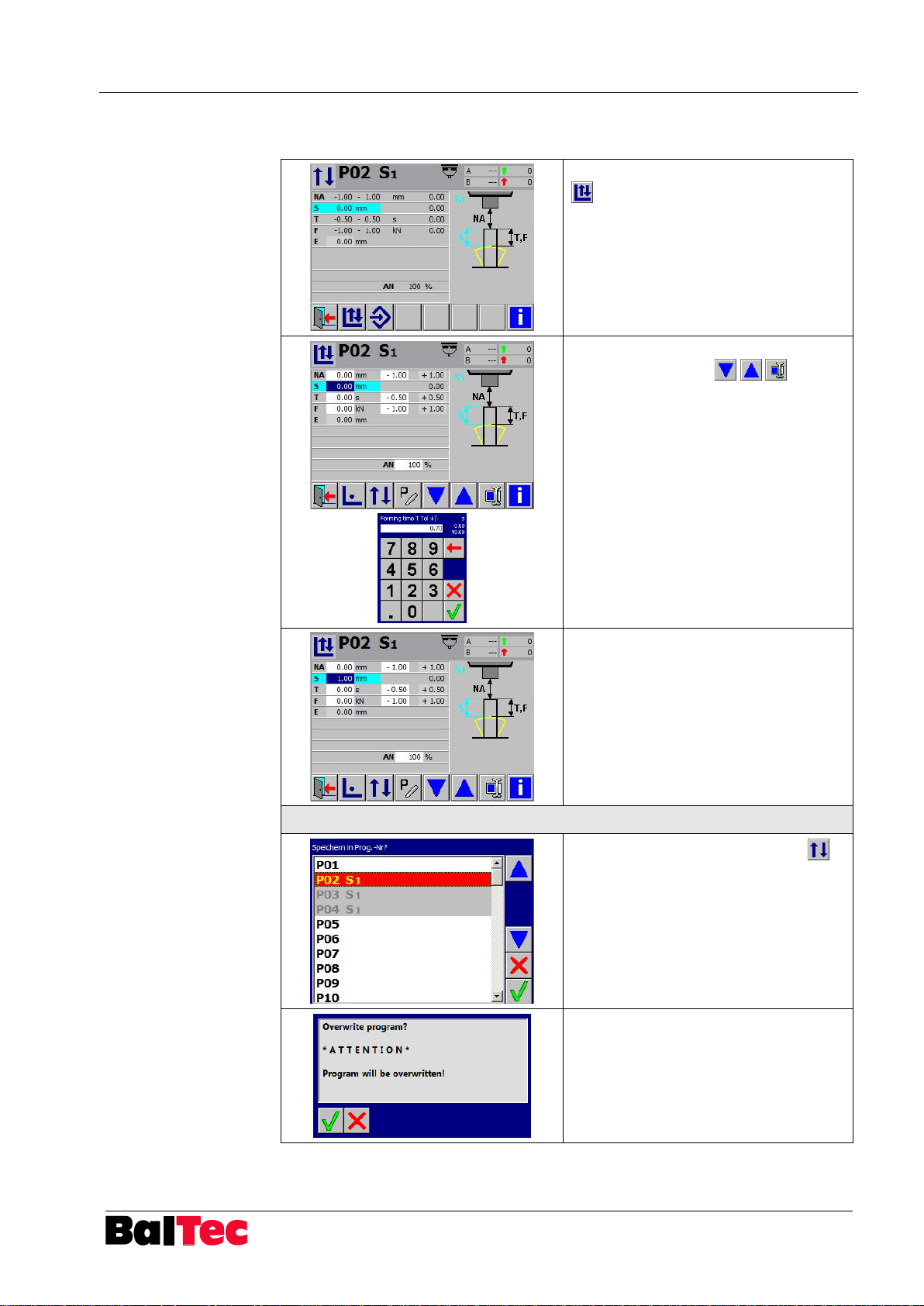
Select key “Correction operating mode“
Adjust reference input variable or
tolerances with keys and
confirm with OK
Actuate a correction riveting
a) saving modified program under the same name:
Select key “Cycle operation mode“
Program-list appears (actual program-
no. is highlighted red)
Confirm with OK key
Window “Overwrite program?” appears
Confirm with OK key
5.9.2 Modify/copy riveting program
Page 38
Operation Process-Controller HPP - 25
38
803699.017/ENG
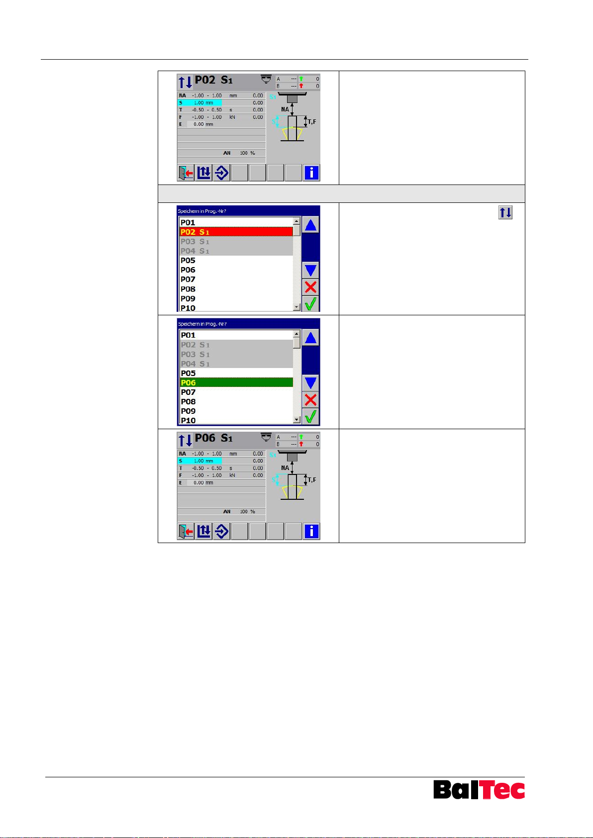
Program is saved under same number.
Program returns to “Cycle operating
mode”
b) saving modified program under a new name:
Select key “Cycle operating mode“
Program list appears (actual program
number is highlighted red)
Select free program number (free new
program number is highlighted green)
and confirm with OK key.
Program with new number saved
Program returns in “Cycle operating
mode”
Page 39
Process-Controller HPP - 25 Operation
803699.017/ENG
39
In “Correction operating mode”
asymmetric tolerances can be entered
by selecting the plus tolerance and
entering the desired tolerance.
If the entered plus tolerance has the
same value as the minus tolerance, the
screen switches on +/- tolerance (plus
tolerance field has again the grey
background)
NOTICE
The input option and display of a manual trigger is adjusted by activation of
parameter 43 = 1.
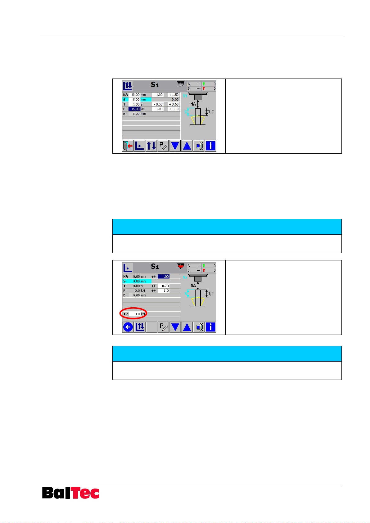
Example: Setup operating mode
riveting mode S1 with active trigger
NOTICE
If TR is adjusted on 0.0kN, NA is automatically detected as if TR were not
activated.
5.10 Riveting programs special functions
5.10.1 Asymmetric tolerances
5.10.2 Manual trigger TR
In all riveting modes with NA detection – except riveting modes with external NA
detection – the rivet front end can be defined by predefinition of a fix force
threshold.
This can be necessary e.g. when using a pressure pad.
Page 40
Operation Process-Controller HPP - 25
40
803699.017/ENG
NOTICE
The input option and display of an analog value is adjusted by activation of
parameter 13 = 1 (analog module active).
A default analog value for new programs can be adjusted in parameter 14.
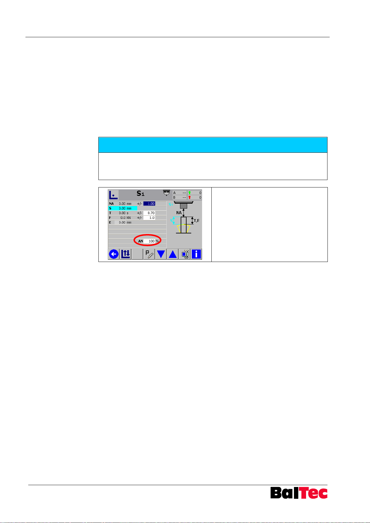
Example: Setup operating mode
riveting mode S1 with analog value
activation.
5.10.3 Analog value AN for pressure or speed selection
If a PVM module (see options) is installed in HPP-25, 2 analog values as outputs
are available:
1. 4 – 20mA, or
2. 0 – 700mA
Analog value AN input
The desired analog value can be entered in the field “AN” in the riveting program.
This analog value is only valid in the actual riveting program shown on the display.
This means, for each riveting program a different value can be adjusted.
Analog value AN for pressure selection
The analog value AN for pressure selection is a current between 4 – 20mA which
is visualised with 0 – 100% (0% = 4mA, 100% = 20mA). The proportional pressure
control valve will then set the air pressure “proportional” to the level of current resp.
percentage.
Example:
Machine is connected to air pressure which must have a minimum of 6 bar. The
proportional pressure regulating valve will set the maximum (according to the
information of the valve) to 6 bar (100%). This means, an analog input of 50%
corresponds approximately 3 bar.
Depending on the machine size, the minimum possible operation pressure is about
30% (2bar).
Analog value AN for speed selection
The flow rate for the approach speed of the riveting spindle is set by a volume flow
rate regulating valve (ex. RNE 481). The analog value AN for speed selection is a
current between 0 – 700mA which is visualised with 0 – 100% (0% = 0mA, 100% =
700mA). The volume flow rate regulating valve will then set the feed rate
“proportional” to the level of current resp. percentage.
Page 41
Process-Controller HPP - 25 Operation
803699.017/ENG
41
NOTICE
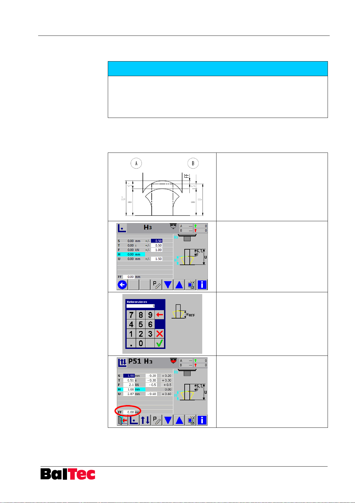
The input option and display of a form factor is adjusted by activation of
parameter 44 = 1 (form factor active).
During setup riveting the form factor has to be 0!
If a form factor should be entered on the basis of the form tool profile, the head
must be formed completely during setup riveting!
1. Measure rivet height (U‘) before
riveting
A = after setup
B = after correction riveting with form
factor
2. Select setup riveting mode H3 –
form factor FF has to be 0
3. Execute setup riveting – riveting
head must be formed completely
4. Window reference height appears
5. Measure H at completed rivet and
enter measure as reference
6. Main window correction appears
Reported U differs from the measured
U’ by the form factor
7. Form factor FF = U‘ – U
8. Execute again a riveting in the
correction operating mode – U and
S are displayed now due to the
corrected form factor
5.10.4 Form factor FF
In riveting modes H measuring errors at closing head height, due to the form tool
profile and riveting stroke, can be adjusted.
Example (riveting mode H3):
Page 42
Operation Process-Controller HPP - 25
42
803699.017/ENG
NOTICE
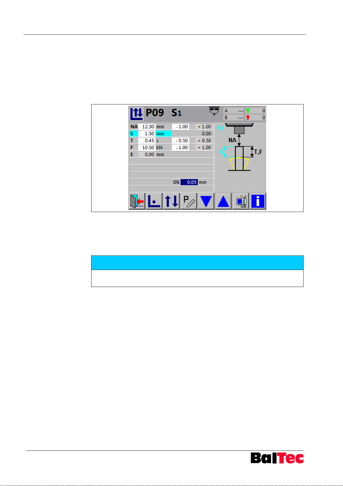
The input option and display of the offset value is adjusted by activation of
parameter 86 = 1.
5.10.5 Control variable offset value (OS)
The switch-off point of riveting cycle can be brought forward by entering an offset
value, so that the physically induced overshoot is compensated.
In this way the reached control value correspond as possible the given and the
displayed control variable.
The necessary offset value is determinated with a correction riveting (OS has to be
equal to zero) and then entered. The value must be positive.
Example (see picture):
S = 1.5mm, OS = 0.05mm
Riveting cycle will be stopped at S = S – OS = 1.50 – 0.05 = 1.45mm
Page 43
Process-Controller HPP - 25 Operation
803699.017/ENG
43
NOTICE
The input option and display of the switching point is adjusted by activation of
parameter 73 = 3.
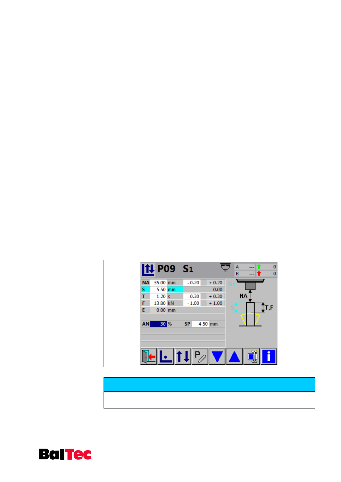
5.10.6 Rapid speed/working speed valve output switching point (SP) relative to control variable
The valve output for Rapid speed/working speed (PVM module required – X5) can
also be activated via a switching point.
The switching point (SP) is defined as value of control variable (mode S: starting
from a value S).
In addition to this well-known function Rapid speed/working speed (RNE 481 and
long-stroke machines) in connection with a proportional pressure control valve can
be switched on a lower pressure during the riveting process ( -> effect: How
"riveting out" on the stroke limiting stop).
Example
Mode S1
S
SP = 4.5mm (SP must be smaller than S
nominal
= 5.5mm
nominal
)
AN = 30%
The valve output switching point (SP) shall be set 4.5mm before reaching S
nominal
The riveting cycle will start with the max. pressure (the one shown on the input
manometer). When reaching the switching point SP, the pressure will drop to 30%
(set AN value) of the max. operating pressure and the rest of the riveting cycle (SP
= 4.5mm) will be executed with the lower pressure.
Input of switching point (SP) can be entered only in correction operation mode.
Result
The riveting cycle starts quickly forming the rivet with a max. pressure. When
reaching the switching point (SP), the pressure drops and ends the riveting cycle at
a low pressure, this means, the end of forming will need more time but it will
smoothen out the surface of the rivet.
The smooth finishing is used, when the rivet has not the same resistance over the
complete cycle, like for example hollow rivet which tend to buckle, when the
diameter gets bigger.
.
Page 44
Operation Process-Controller HPP - 25
44
803699.017/ENG
NOTICE
The input option and display of the switching point is adjusted by activation of
parameter 73 = 4.
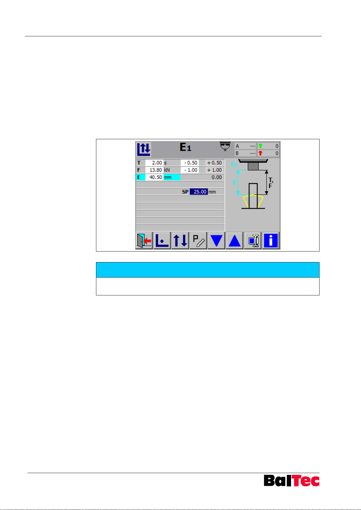
5.10.7 Rapid speed/working speed valve output switching point (SP) relative to spindle path E
The valve output for Rapid speed/working speed (PVM module required – X5) can
also be activated via a switching point.
The valve is switched without an additional initiator at output A 4.7.
The switching point (SP) is activated when the value E (spindle path) is reached.
Example
Mode E1
E = 40.5mm
SP = 25mm (SP must be less than E)
The valve output switching point shall be set at E = 15.5mm.
Page 45
Process-Controller HPP - 25 Operation
803699.017/ENG
45
NOTICE
The input option and display of riveting timeout TX is adjusted by activating
parameter 87 = 1.
5.10.8 Riveting timeout (TX)
The function riveting timeout (TX) is monitoring the impact of the touch probe onto
the base within an adjusted time. If the base is not detected within this time TX, the
riveting cycle is aborted.
Application
When using NHE-H: TX = time, until path “min. path time H” (parameter 34)
For all riveting modes, that select an external switch signal (X14) to detect
must be measured
the rivet front end NA (example: S3, T2, F3, E4…)
Page 46
Operation Process-Controller HPP - 25
46
803699.017/ENG
NOTICE
The input option and display of rivet detection NX value is adjusted by activating
parameter 88 = 1.
If parameter is activated, the value NX is shown (only in riveting modes with NA
detection).
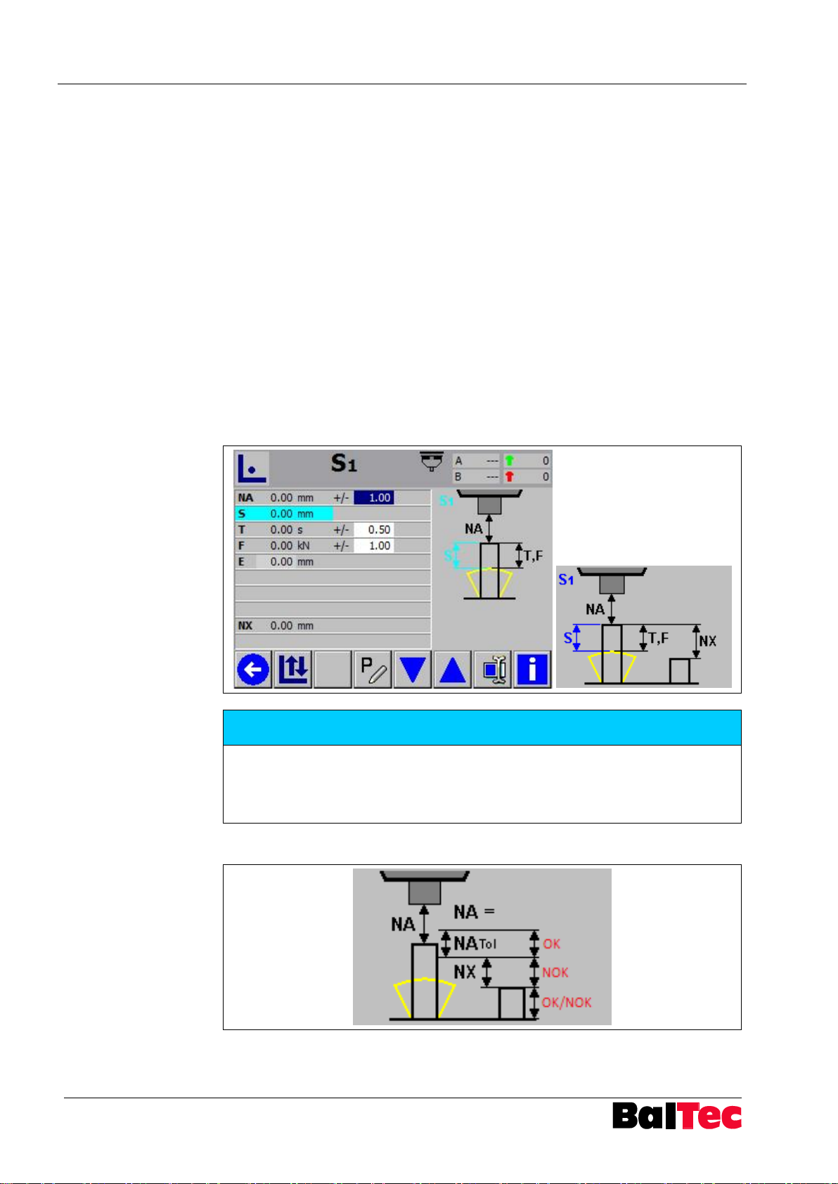
5.10.9 Rivet detection NX
If the function “Rivet detection NX“ is activated, the control can verify, if a rivet is
out of tolerance or not present.
Example 1
NA
Rivet front end is within the NA tolerance. No abort of riveting cycle because of NA
violation. Riveting result is OK.
Example 2
NA
Rivet front end is within the adjusted value NX, measured from rivet front end plus
tolerance. Abort of riveting cycle because of NA violation. Rivet is too short.
Riveting result is NOK.
Example 3
NA
No rivet front end is detected within NX. This means, no rivet is present. The part
must not be evaluated as NOK. Abort will be after reaching adjusted value NX.
Riveting result NOK and OK are set together (NA value on touch screen is orange).
act
act
act
≙ NA
< NA
> NA
until NA
Tol-
+ NX → NOK
Tol+
+ NX → NOK/OK
Tol+
Tol+
Explanation OK / NOK signal:
Page 47
Process-Controller HPP - 25 Operation
803699.017/ENG
47
Check
Output signal OK/NOK
Component
present
Rivet
present
yes
yes
OK or NOK according to
riveting result
Finish riveting cycle
no
no
OK/NOK
Stop riveting cycle after
check
yes
no
NOK
Stop riveting cycle after
check
no
yes
NOK
Stop riveting cycle after
check
NOTICE
The input option and display of rivet and component detection is adjusted by
activating parameter 88 = 2.
If parameter is activated, the value NX is shown (only in riveting modes with NA
detection).
5.10.10 Rivet and component detection
With the function “Rivet and component detection“ the controller can check if a
component (by monitoring B) and a rivet (by NA and NX) is present.
Can only be done in riveting mode S2, T5 and H8 and by using the riveting stroke
limit switch unit NHE-U.
Following conditions can be analysed and evaluated by the controller:
Procedure example (riveting mode H8)
1. Set following parameters:
- 33 = 0 (path measurement E → path-measuring system at riveting
spindle)
- 75 = 2 (NHE for projection measurement)
- 88 = 2 (rivet and component detection active)
2. Use value B with tolerance to check the presence of component (base)
a) if value B is within the tolerance – carry on
b) if value B is outside the tolerance – carry on and check NX
3. Check rivet front end with function NX (see chapter “Rivet detection NX“)
Page 48
Operation Process-Controller HPP - 25
48
803699.017/ENG
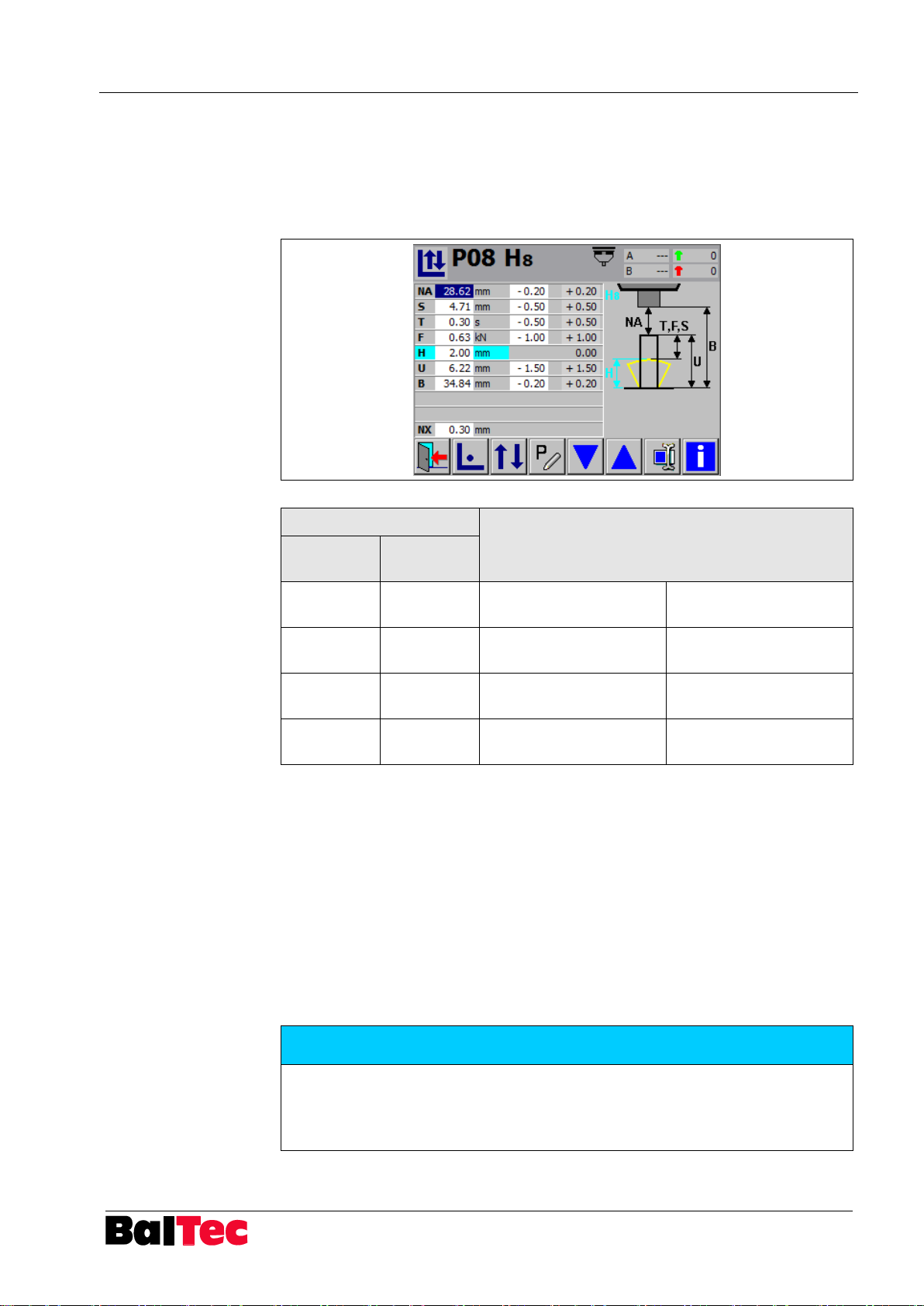
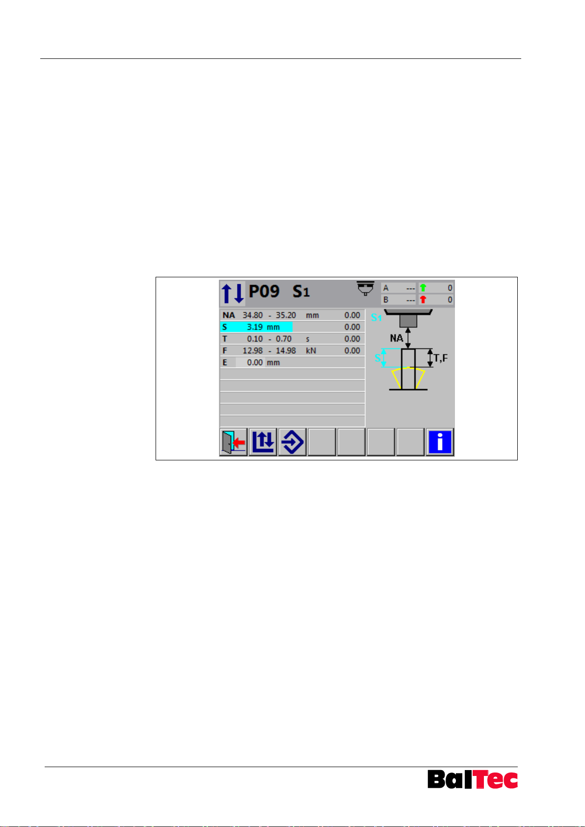
5.10.11 Tolerance abort
Any violation of tolerances will stop immediately the riveting cycle when parameter
58 “tolerance abort” is activated in the control. Following settings are possible:
Parameter 58 = 0
Riveting cycle is stopped immediately only when NA, U or B tolerance is violated
Parameter 58 = 1
Riveting cycle is stopped immediately when any tolerance is violated.
Example for riveting mode S1
Parameter 58 = 0:
If NA is detected within the tolerance, the cycle continues until S = 3.19mm is
reached, even if riveting time T exceeds 0.7 seconds – until max. riveting time.
Parameter 58 = 1:
If riveting time T exceeds 0.7 seconds, the riveting cycle would be stopped
immediately and T is highlighted as error.
Page 49
Process-Controller HPP - 25 Operation
803699.017/ENG
49
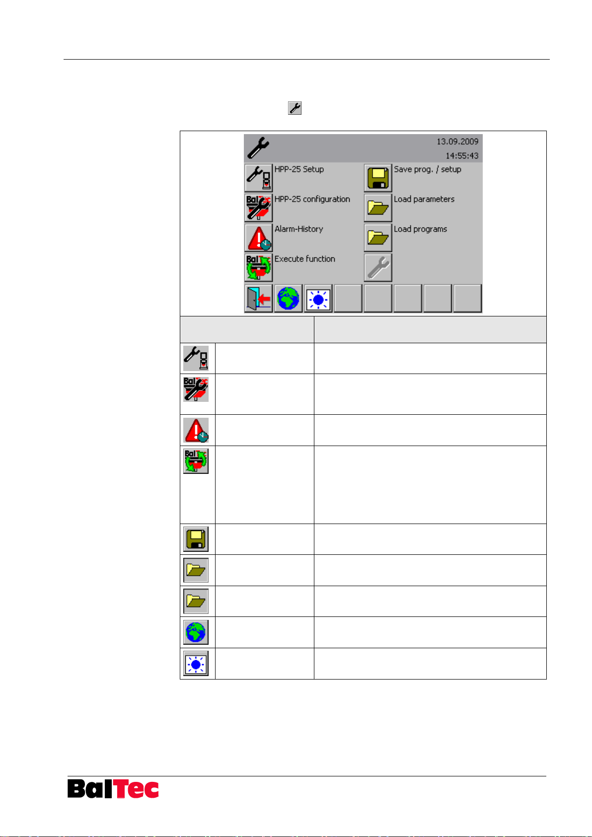
Symbol
Description function
HPP-25 Setup
Access to setup table (parameter list)
HPP-25
configuration
- Password modification
- Machine no. input
- Ethernet address
Alarm-History
Display of last error messages
Execute function
Following functions can be executed:
- Reset factory settings
- Touch screen calibration
- Load update
- Activate auto compensation
- Delete riveting programs
Save prog. / setup
Save programs, setup parameters and AlarmHistory on USB
Load parameters
Load parameters from USB
Load programs
Load programs from USB
Choose language
Language modification
Screen contrast
Screen contrast adjustment
5.11 Tools
By selecting key “Tools“ in main menu, below shown window opens. Further
functions can be selected by the respective key.
Page 50
Operation Process-Controller HPP - 25
50
803699.017/ENG
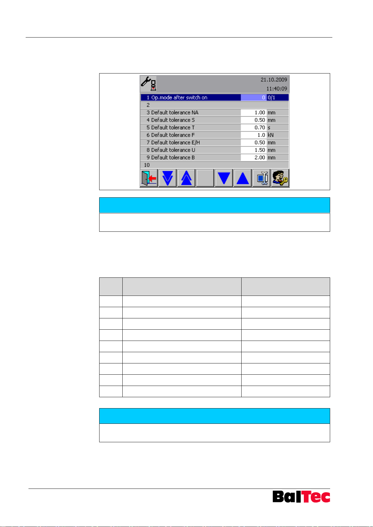
NOTICE
The factory settings are set according to the customer order. The values listed in
the setup table are default values and may deviate from the factory settings!
PWL
Determination / Function
Password
0
Operator
- 1 Foreman
101 2 Setter / Programmer
202 3 unimplemented
4 Process-Controller settings
404 5 Touch screen settings
505 6 Definition HW
606 7 Administrator customer
on request customer
8
BalTec
BalTec employee
NOTICE
The entered password remains so long active as the set holding time in
parameter 66. Subsequently PWL 0 is automatically active again.
5.11.1 HPP-25 Setup
In this menu, the parameters of the process controller can be configured.
5.11.1.1 Password levels PWL
Access to certain functions or parameter settings are protected with passwords.
The passwords are factory-assigned and can be changed by the customer if
required.
Page 51
Process-Controller HPP - 25 Operation
803699.017/ENG
51
Page 1
Page 2
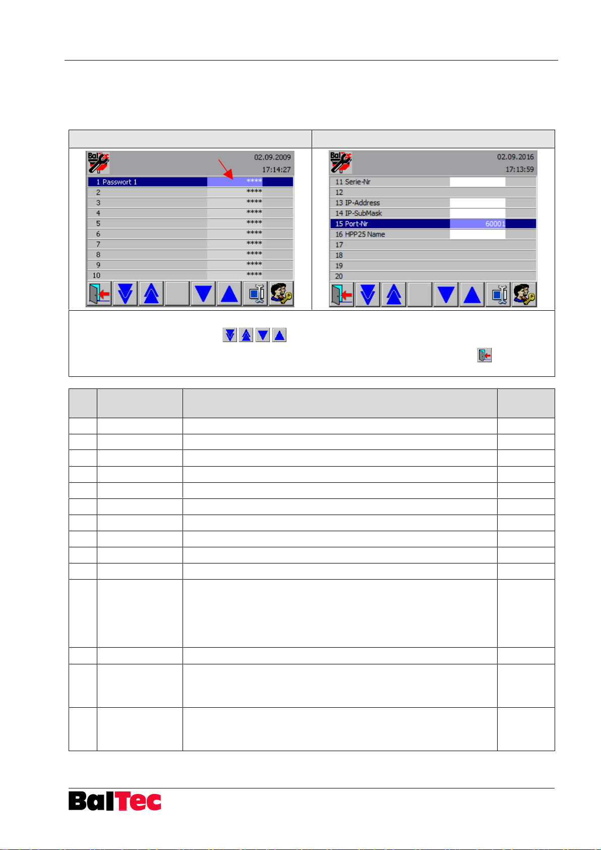
Procedure:
1. Select desired line with keys
2. Select light blue (****) column
3. Number keyboard appears
4. Enter new password, number or address and
confirm with OK
5. Exit menu with “previous page“
No.
Configuration
Description
PW-Level
1
Password 1
Enter new password for PWL 1
2 2 Password 2
Enter new password for PWL 2
3
3
Password 3
Enter new password for PWL 3
4
4
Password 4
Enter new password for PWL 4
5 5 Password 5
Enter new password for PWL 5
6
6
Password 6
Enter new password for PWL 6
7
7
Password 7
Modification by BalTec only
8 8 Password 8
No access
9
9
Password 9
No access
10
10
Password 10
No access
11
11
Serial no.
Serial no. of riveting machine
Format: XXX.XXXX
By saving parameters and riveting programs a folder with this
number is created on the USB stick
Only data from folder with this number can be loaded
6
12
13
IP-Address
IP address of Process-Controllers HPP-25
Input format: XXX.XXX.XXX.XXX
Required when using Ethernet interface
6
14
IP-Submask
IP submask of Process-Controllers HPP-25
Input format: XXX.XXX.XXX.XXX
Required when using Ethernet interface
6
5.11.2 HPP-25 configuration
In the HPP-25 configuration passwords can be changed, machine number and
Ethernet addresses can be entered.
Page 52

Operation Process-Controller HPP - 25
52
803699.017/ENG
No.
Configuration
Description
PW-Level
15
Port no.
Port no. of Process-Controller HPP-25
Standard setting: 60001
Can be modified
6
16
HPP25 name
Input of additional name (will be shown in PCTool when searching
for HPP in the network)
Page 53
Process-Controller HPP - 25 Operation
803699.017/ENG
53
NOTICE
By saving parameters on the USB stick also the Alarm-History will be saved.
The saved Alarm-History can be read with the software “HPP25-PcTool“.
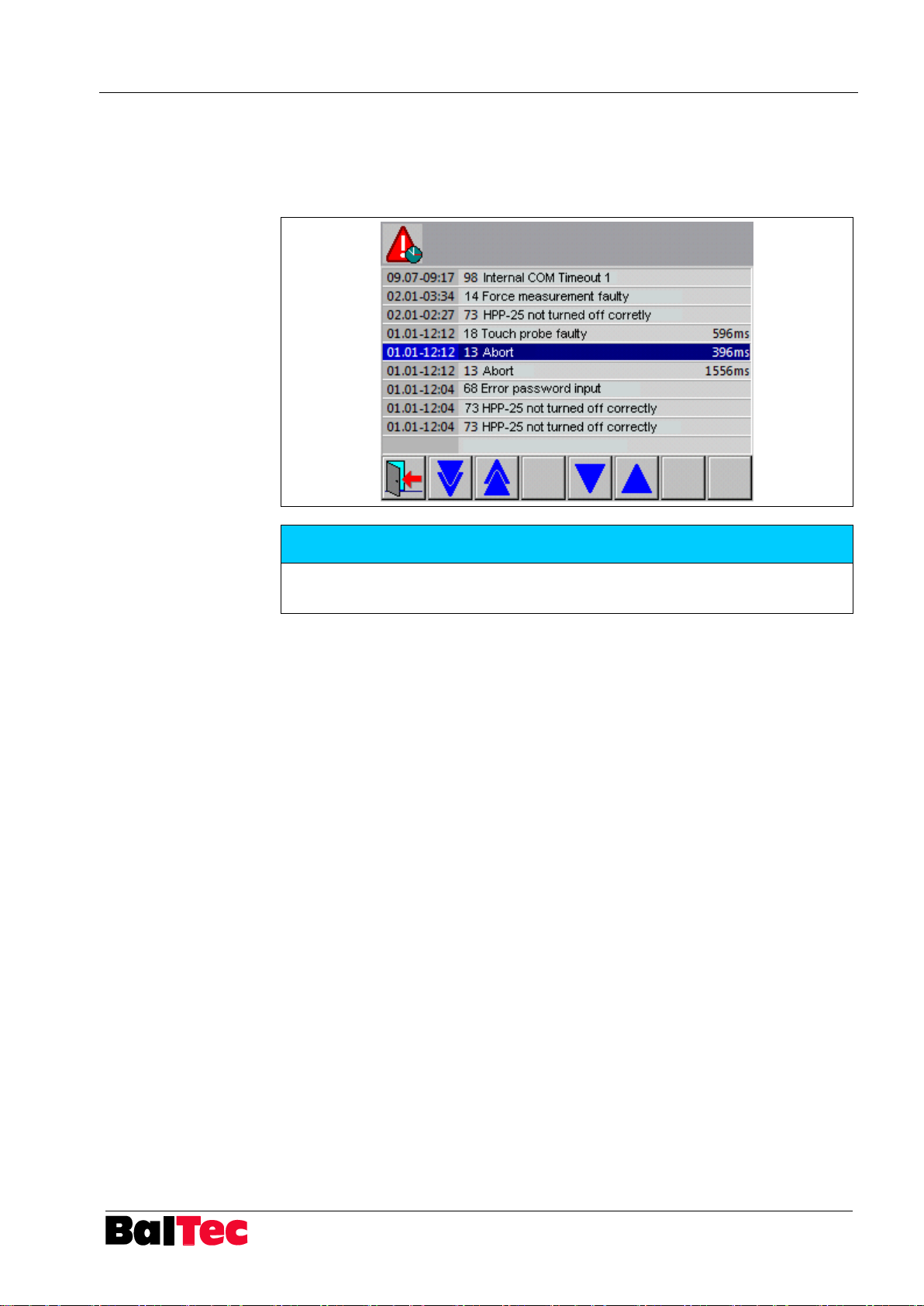
5.11.3 Alarm-History
In alarm history, the last error messages can be viewed. All entries are timestamped. The number before the description is the error number (see also chapter
"List of error messages”).
Page 54

Operation Process-Controller HPP - 25
54
803699.017/ENG
PWL
Function
5
Factory-Reset
The internal saved factory settings of parameter are reloaded.
5
Touch calibration
If the touch screen would not respond correctly, with this function it can
be recalibrated.
Follow the instruction on the touch screen
5
Load HPP-25 Update (from USB stick)
Load new HPP-25 software or new language file.
Procedure:
Create folder with denomination “HPP25 update“ on USB stick
(Attention: space between HPP25 and update must be present!)
save new operating software or new language file in this folder
Plug USB stick into USB interface of Process controller
Execute function “Load HPP-25 Update“
Subsequently the controller shuts down automatically and starts again.
Newly loaded files are displayed briefly.
6
Activate auto compensation
Enter activation code for auto compensation – costly option
7
Delete all riveting programs
5.11.4 Execute function
Page 55
Process-Controller HPP - 25 Operation
803699.017/ENG
55
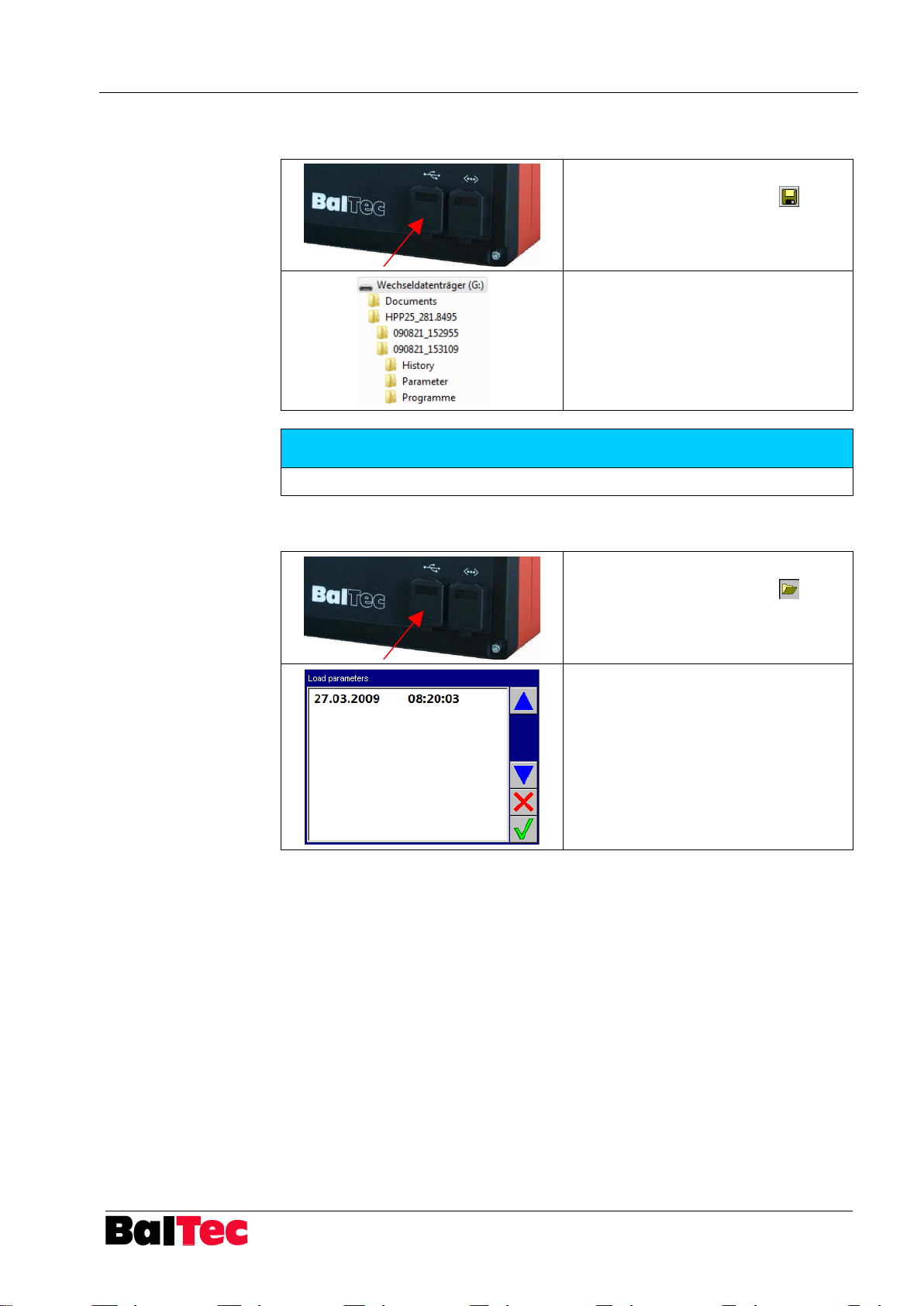
Plug USB stick into USB interface
Select key “Save prog./setup“
As shown left, data are saved
automatically in the corresponding
folder on the USB stick
Unplug USB stick
NOTICE
Alarm-History and parameters can be read with the software “HPP25-PcTool“.
Plug USB stick into USB interface
Select key “Load parameters“
Select desired folder with date (only
folder with identical machine no. are
displayed)
Confirm with key OK
Only complete parameter lists can be
loaded
5.11.5 Save programs/setup
5.11.6 Load parameters
Page 56
Operation Process-Controller HPP - 25
56
803699.017/ENG
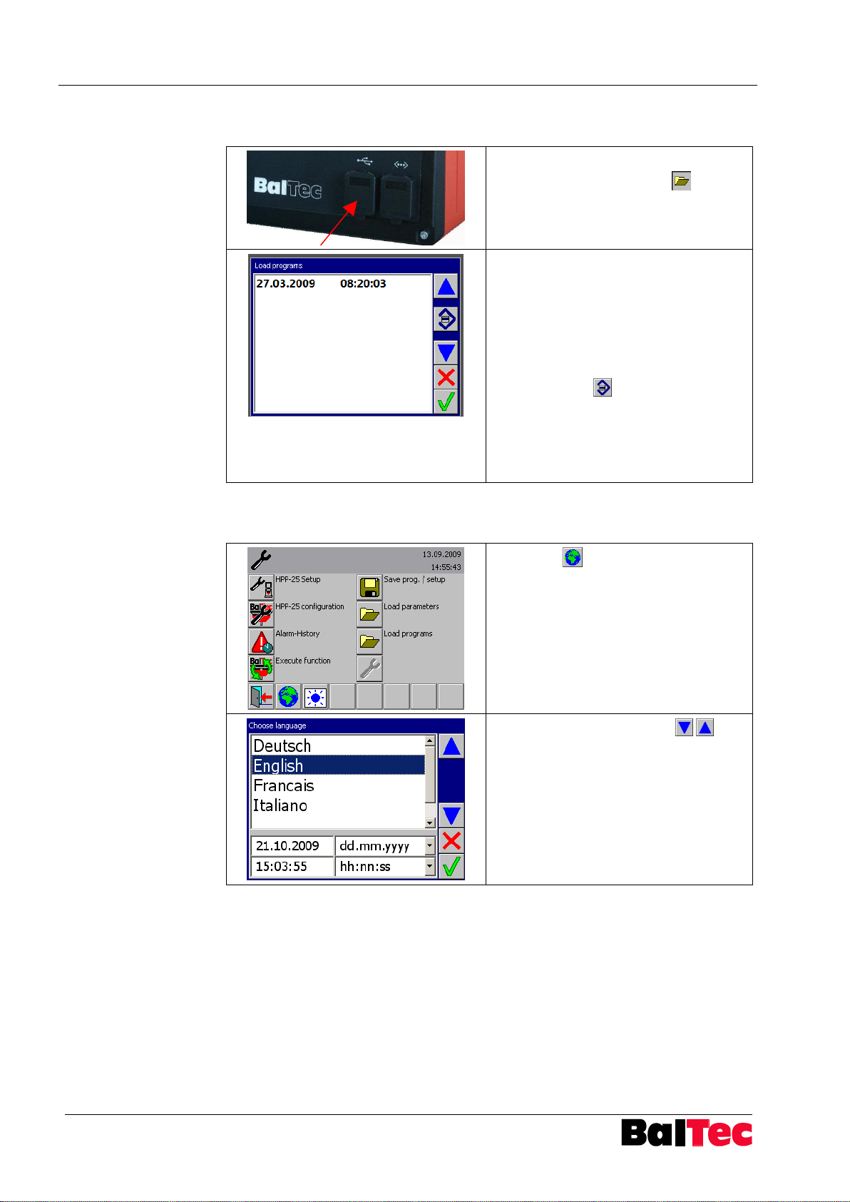
Plug USB stick into USB interface
Select key “Load programs“
Select desired folder with date
a) Select all loaded programs:
1. Select desired folder with date
2. Press key OK
b) Select only certain programs
1. Select desired folder with date
2. Select key
3. Programs of selected folder with
date are displayed
4. Select desired programs
5. Press key OK
Select key
Select language with arrows and
confirm with OK
5.11.7 Load programs
5.11.8 Choose language
Page 57
Process-Controller HPP - 25 Operation
803699.017/ENG
57
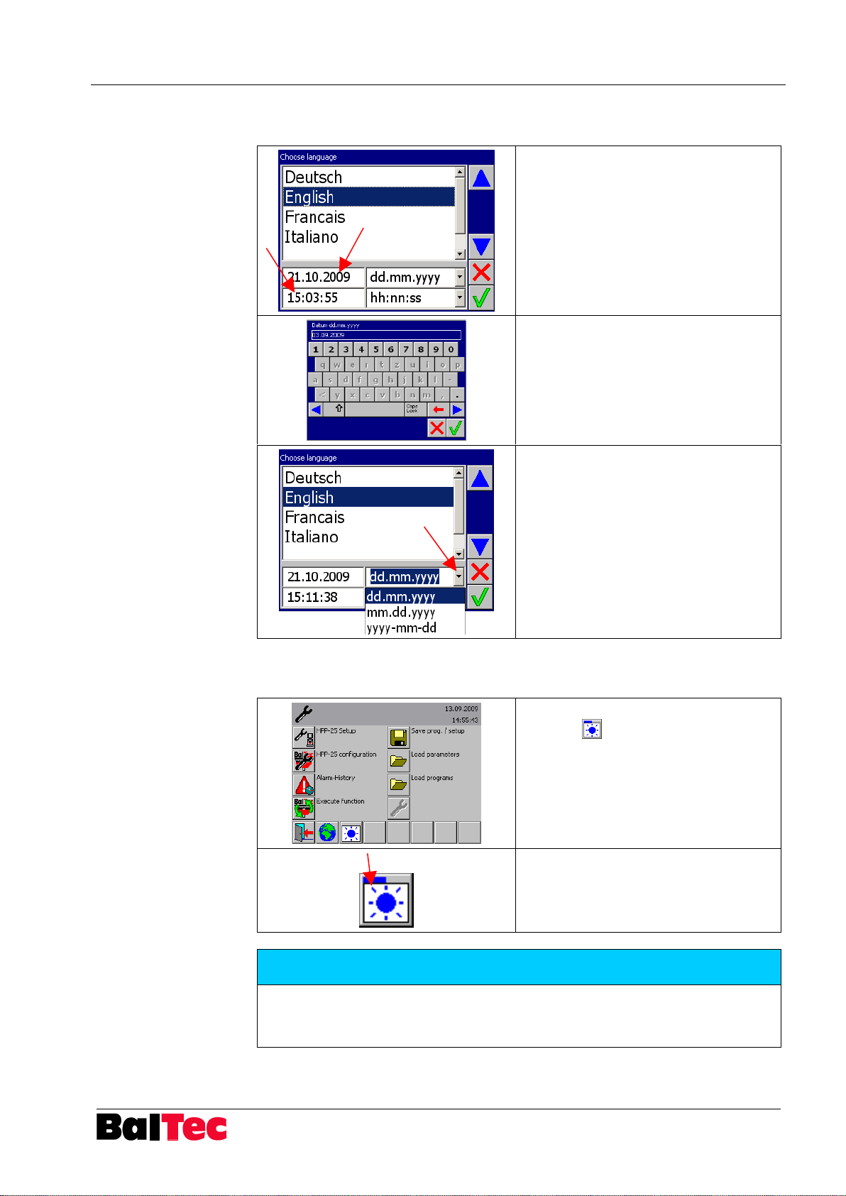
Select date respectively time
Enter date respectively time and
confirm with key OK
Adjust date format:
Select arrow and adjust date format
Confirm with key OK
By pressing repeatedly key “screen
contrast” the screen becomes
brighter
A blue progress indicator above the
symbol indicates the brightness value
NOTICE
The brightness can be adjusted only in one direction (+)!
When reaching the maximum adjustment by pressing again the symbol it returns
to the minimum adjustment!
5.11.8.1 Date and time adjustement
5.11.9 Screen contrast adjustment
Page 58
Operation Process-Controller HPP - 25
58
803699.017/ENG
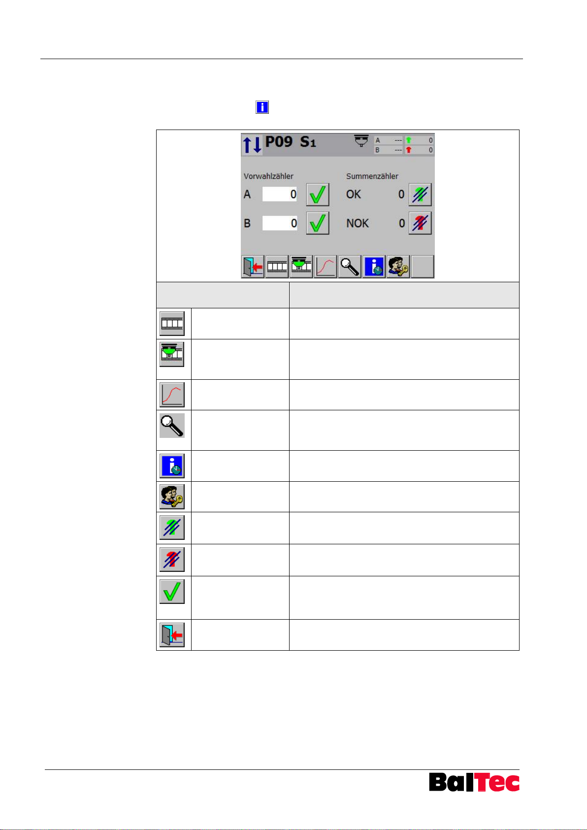
Symbol
Function description
Logger data
Display of automatically recorded data of riveting
process
Online logger data
in cycle operating
mode
Display online logger data in cycle operating mode.
The latest 10 cycles can be shown. Display is
erased when controller is switching-off.
Riveting curve
display
Graphical display of process data
Diagnosis inputs
and outputs sensor
system
Assignments display of the internal inputs and
outputs
Information: riveting,
hours, SW, HW
Display of hour counter, executed riveting,
software and hardware version
Enter password
Access to certain functions or parameter settings
(see chapter “Password levels“)
OK counter reset
OK riveting total counter reset
(PWL 1 necessary)
NOK counter reset
NOK riveting total counter reset
(PWL 1 necessary)
OK
Batch counter A or B: Confirm and reset to default
value
(PWL 1 necessary)
Previous page
Back to main menu
5.12 Information
By selecting key “Info“ in main menu, below shown window opens. Further
functions can be selected by the respective key.
Page 59
Process-Controller HPP - 25 Operation
803699.017/ENG
59
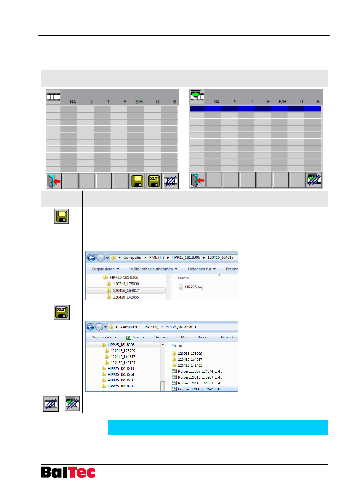
Logger data display
Online logger data display in cycle operating
mode
Symbol
Function description
Logger data can be saved on the USB stick. Short storage time.
The logger data can be opened in PCTool (from PCTool version 1.0.2.3) and then saved as
Excel.
Memory location .log File:
HPP25_Machine no.\File date_time\
Save logger data as Excel file on the USB stick. Storage time is longer (example: 10‘000
logger lines: ca. 3min.; 30‘000 logger lines need ca.11min.)!
All logger data are deleted
NOTICE
Logger data can be read with the software “HPP25-PcTool“ or Excel.
5.12.1 Logger data
In this menu, the logger data are displayed.
Page 60
Operation Process-Controller HPP - 25
60
803699.017/ENG
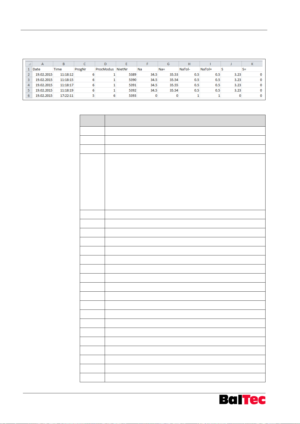
Column
Description
Date
Logger date
Time
Logger time
ProgNo.
Riveting program no.
Proc
Mode
Number for description riveting mode
1=S1
2=S2
3=S3
4=S4
5=S5
6=T1
7=T2
8=T3
9=T4
10=T5
11=T6
12=T7
13=T8
14=T9
15=T10
16=T11
17=T12
18=T13
19=T14
20= F1
21=F2
22=F3
23=F4
24=E1
25=E2
26=E3
27=E4
28=E5
29=E6
30=E7
31=N1
32=N2
33=N3
34=N4
35=H1
36=H2
37=H3
38=H4
39=H5
40=S6
41=T15
42=H6
43=T16
44=H7
45=H8
NietNr.
Consecutively numbering
Na
Rivet front end nominal value
Na=
Rivet front end actual value
NaTol-
Rivet front end minus tolerance
NaTol+
Rivet front end plus tolerance
S
Forming path nominal value
S=
Forming path actual value
STol-
Forming path minus tolerance
STol+
Forming path plus tolerance
T
Riveting- / Forming time nominal value
T=
Riveting- / Forming time actual value
TTol-
Riveting- / Forming time minus tolerance
TTol+
Riveting- / Forming time plus tolerance
F
Riveting force nominal value
F=
Riveting force actual value
FTol-
Riveting force minus tolerance
FTol+
Riveting force plus tolerance
E/H
Path E / Closing head height H nominal value
E/H=
Path E / Closing head height H actual value
5.12.1.1 Logger data in Excel
Saved logger data can be read and evaluated in MS Excel.
Description of columns in Excel table:
Page 61
Process-Controller HPP - 25 Operation
803699.017/ENG
61
Column
Description
E/H-
Path E / Closing head height H minus tolerance
E/H+
Path E / Closing head height H plus tolerance
U
Rivet projection nominal value
U=
Rivet projection actual value
UTol-
Rivet projection minus tolerance
UTol+
Rivet projection plus tolerance
B
Base nominal value
B=
Base actual value
BTol-
Base minus tolerance
BTol+
Base plus tolerance
SNB
Riveting base nominal value: After input of H
Ref
this value is
calculated.
SNB = Value E (setup riveting) + H
Ref
STO
Touch probe offset nominal value (TO value from reference value)
TO
Touch probe offset value
FF
Form factor
KO
Compensation
PR
Progression
TR
Trigger level
AN
Analogue value
OS
Control variable offset value
SP
Rapid speed/working speed valve output switching point
TX
Riveting timeout, nominal value TX in riveting program
NX
Rivet detection, nominal value NX in riveting program
TT
IstPM
Riveting mode used for evaluation (S6 or T15)
S6: S1 or T4 used for evaluation (IstPM = 1 or 9)
T15: T4 or H6 used for evaluation (IstPM = 9 or 42)
TX=
Riveting timeout, actual value
IB
InfoBit, 1 = no rivet present (function NX active)
NB
Riveting result evaluation: Sum of all bit error
1=Error NA
2=Error S
4= Error T
8=Error F
16=Error E/H
32=Error U
64=Error B
128=Error TX
If sum 255: Abort during riveting process
AB
Internal code
Page 62
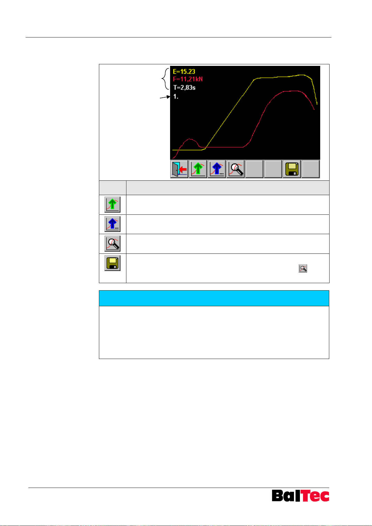
Operation Process-Controller HPP - 25
62
803699.017/ENG
max. values
curve counter
Symbol
Function description
Last riveting curve is selected
Previous riveting curves are selected
Detail view of riveting curve is displayed
Riveting curves can be saved on the USB stick
If the detail view of riveting curve should be saved, select key before
saving
NOTICE
Riveting curves can be read with the software “HPP25-PcTool“ or Excel.
All buffered riveting curves are lost when switching off the controller.
Number of saved curves is dependent on the duration of riveting process and
recorded curve resolution (see also parameter 60: curve interval).
Maximum 10 seconds can be recorded, if the max. resolution is set to 1ms
(parameter 60).
5.12.2 Riveting curve display
Page 63
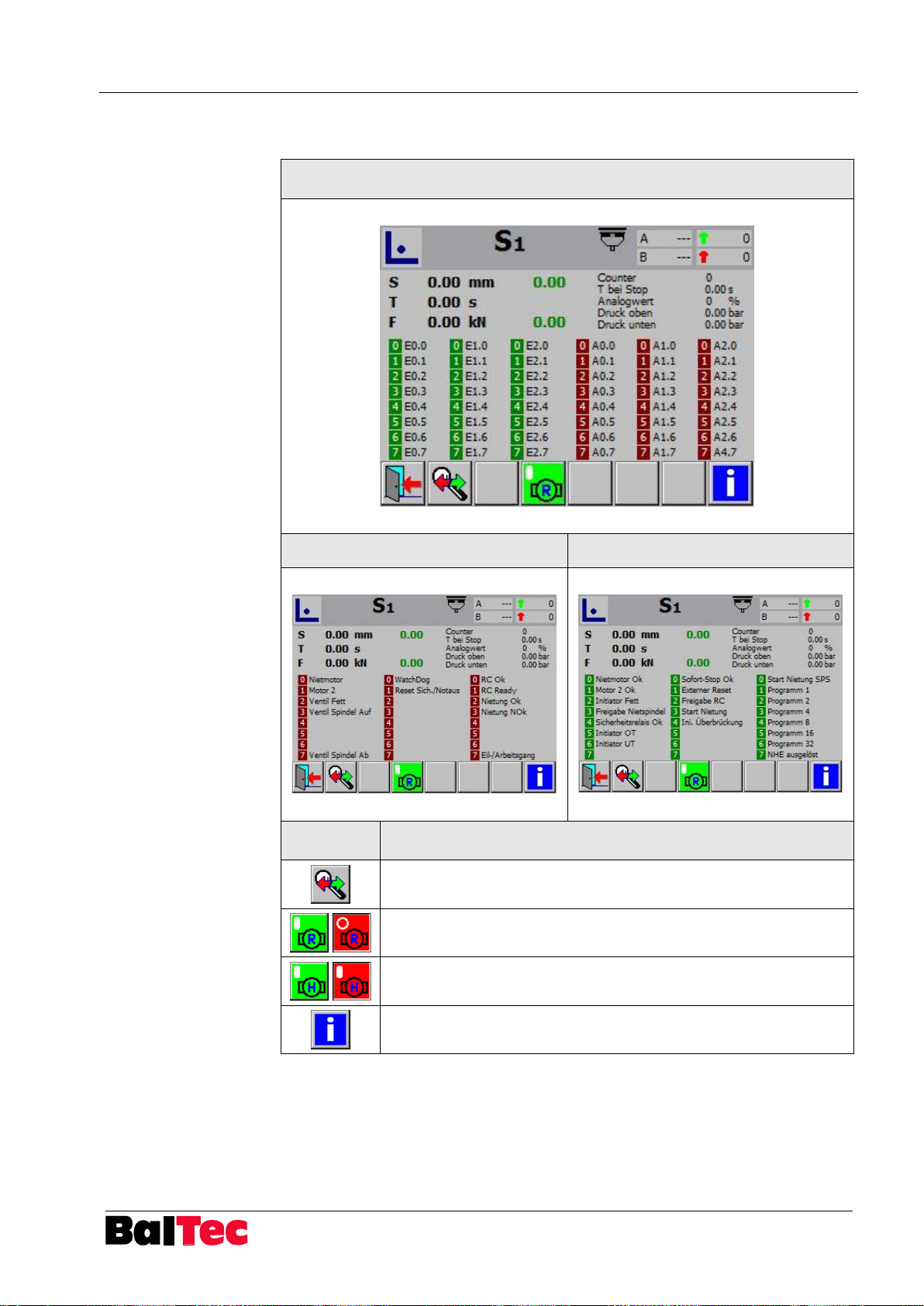
Process-Controller HPP - 25 Operation
803699.017/ENG
63
Internal inputs and outputs diagnosis window
Output diagnosis window
Input diagnosis window
Symbol
Function description
Change diagnosis window
Switching the riveting motor ON and OFF
Switching the motor 2 ON and OFF
Back to information window
5.12.3 Diagnosis inputs and outputs sensor system
Page 64
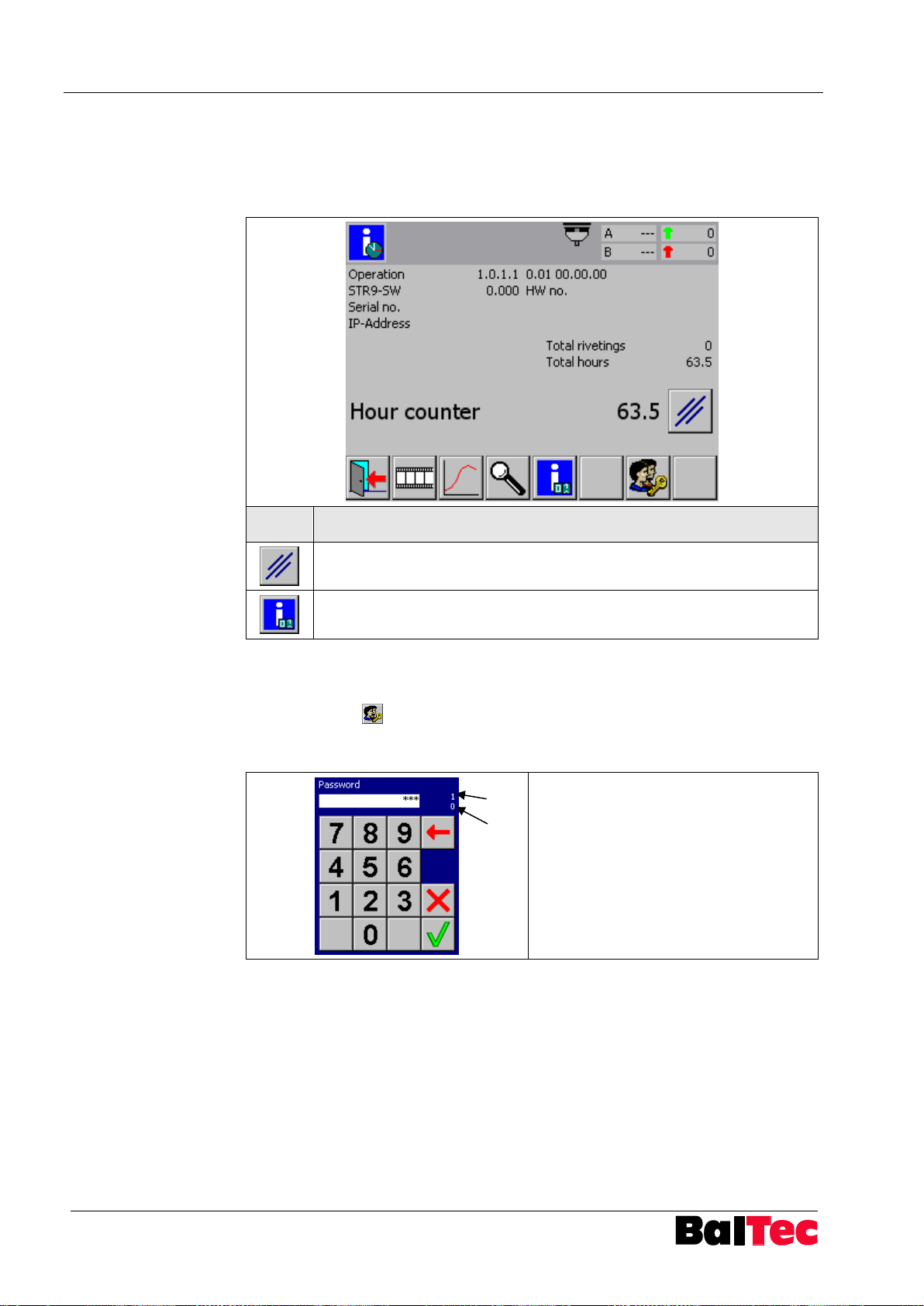
Operation Process-Controller HPP - 25
64
803699.017/ENG
Symbol
Function description
Hour counter reset (PWL 1 necessary)
Back to window batch and total counter
Top right in window 2 numeric
character are displayed
Cipher A: necessary PWL for desired
function
Cipher B: current active PWL
(PWL = Password level)
A
B
5.12.4 Information: riveting, hours, SW, HW
In this window following information are displayed: SW version, HW version, serial
no. (machine no.), IP address, total executed riveting, operating hours (hour
counter) and total operating hours.
5.12.5 Enter password
By selecting key or a password protected function below shown window opens.
Entering a password you receive access to certain functions or parameter settings
(see chapter “Password levels PWL “).
Page 65
Process-Controller HPP - 25 Options
803699.017/ENG
65
NOTICE
Functions of the PLC interface are only active when parameter 80 is set to 1.
Inputs
E 2.0
Riveting start (for Cycle operating mode only)
Recommended: Permanent signal until riveting result is
acknowledged (OK / NOK message)
E 2.1-E 2.6
Select program number inputs
Always selected is the program which is present at riveting start
at inputs E2.1 to E2.6
If no program number is selected (program 0) the program that
is active on the HPP-25 will be executed.
Outputs
A 2.0
HPP-25 OK
no error in HPP-25 active
A 2.1
HPP-25 READY – ready for a start signal on E 2.0
The following conditions must be fulfilled:
no error in HPP-25 active (A2.0 high)
HPP-25 is in Cycle operating mode
Initiator TDC (E0.5) high
PLC Interface activated (Par. 80 = 1)
A 2.2
Riveting OK – set to 0 in case of start
A 2.3
Riveting NOK – set to 0 in case of start
NOTICE
Riveting start in operating mode Setup and Correction only possible via E1.3.
If no program number is given by PLC (all inputs E2.1-E2.6 are 0) a riveting
program which should be started with PLC start signal can be selected at touch
screen.
6 Options
6.1 PLC Interface
The PLC interface provides additional inputs and outputs for communication with a
PLC.
Page 66

Options Process-Controller HPP - 25
66
803699.017/ENG
NOTICE
Activation: Parameter 80 = 3
“Time eject table” adjustment: Parameter 83 (in 0.1s)
Operating
mode
Operation sequence
Setup
Insert sliding table – Sliding table is locked – Riveting process
release – Sliding table is pulled out
Correction
Insert sliding table – Sliding table is locked – Riveting process
release – Sliding table is pulled out
Cycle
Insert sliding table – Sliding table is locked – Riveting process
release:
- if riveting OK sliding table is ejected automatically
- if riveting NOK sliding table remains locked, unlocking
and ejection by key “Eject sliding table”
6.2 PLC Interface with function for pneumatic sliding table
For further information (if riveting machine is equipped with pneumatic sliding table)
refer to the operating instructions of the riveting machine.
Page 67

Process-Controller HPP - 25 Options
803699.017/ENG
67
NOTICE
Functions of the PVM module are only active if parameter 13 is set to 1 (display
and input option of AN value in riveting program).
6.3 PVM module
The PVM module (Proportional Valve Module) provides analog signals as well as
the output for the activation of rapid speed/working speed valve.
2 analog signals are available:
4-20 mA for a pressure control valve
0-700 mA (pulse width modulated) for a volume flow rate regulating valve
(RNE 481)
Connection versions see Appendix “Connection diagram plug X5“.
6.4 Automatic compensation
With function “Automatic compensation“ larger deviations in component pairing can
be compensated for automatically.
The function will be released by activation code.
For a detailed description, see separate operating instructions.
6.5 UDP protocol secured
By Ethernet interface the riveting data can be readout and processed in a
superordinate PLC or PC.
Communication takes place by UDP protocol secured.
Description of UDP protocol secured see system description 803965 “UDP protocol
HPP-25“.
Page 68
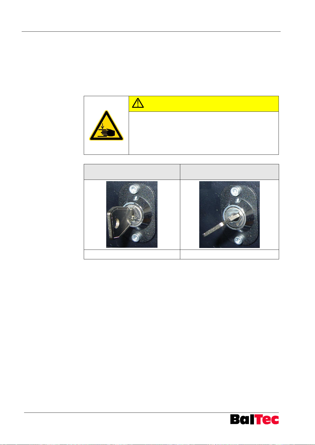
Options Process-Controller HPP - 25
68
803699.017/ENG
CAUTION
Activation of riveting process with foot
switch!
Danger of hand injuries!
Commissioning and operation may only be made by trained
specialist personnel!
Operation with two-hand operating
unit
Operation with foot switch
Key can be extracted
Key can not be extracted
6.6 Change over from operation with two-hand operating unit to operation with foot switch
6.6.1 Key switch
Optionally, the control unit can be equipped with a key switch.
The machine can be switched from operation with two-hand operating unit to
operation with foot switch.
Page 69
Process-Controller HPP - 25 Error rectification
803699.017/ENG
69
NOTICE
With new installations, you must specifically check whether the setup is correct
for your application.
NOTICE
In menu “Diagnosis inputs and outputs sensor system“ or with software
“HPP25-PcTool” the current condition of in- and outputs can be read.
Also the input values of the pressure and path sensors can be controlled.
7 Error rectification
7.1 Introduction
The controller is equipped with monitoring. An incorrect operating condition is
displayed with an error message (number and description).
The error is recorded in menu “Alarm-History” (see chapter “Alarm-History”).
An error is acknowledged with key .
Page 70
Error rectification Process-Controller HPP - 25
70
803699.017/ENG
Error message
Description
Possible cause/Rectification
1
Emergency stop
Emergency stop has been
actuated
Bridge at 34 – 35 missed,
see also parameter 78
2
Instant stop
Instant stop has been actuated
Bridge at 34 – 35 missed,
see also parameter 78
3
Safety circuit
External safety circuit interrupted
or bridge at 15 – 16 missed
Reset external safety circuit
If X6 available: Check external safety
circuit
If X6 not available: Check internal
bridge 15 – 16
4
Riveting motor
Overcurrent riveting motor
Check overload relay (F21)
Check riveting motor
5
Release is missing
Release signal missed
Plug X2: external release signal or
bridge in plug X2 pin 1-2 missing
6
Motor 2
Overcurrent hydraulic motor or
rotary indexing table motor
(RNR)
Check overload relay (F22)
Check overload of motor 2
7
Start X14 false
no NHE connected
8
Timeout NHE
NHE switch not reached
9
Grease empty
Grease container empty
Fill up with grease
Grease monitoring initiator defective
Logic grease monitoring initiator
faulty – Check parameter 22
10
Prog not running
Program has been chosen which
is not admitted
Check setup concerning connected
HW
(path measurement, pressure
measurement, NHE)
11
Timeout TDC
TDC initiator was not switched at
adjusted time
Check parameter 25
12
Timeout BDC
BDC initiator was not switched at
adjusted time
Check parameter 27
13
Abort
Riveting process aborted by
operator
Riveting start (permanent signal)
dropped out before end of riveting
14
Force measurement faulty
Force direction at riveting start
faulty
Change force measurement sensors
plug above/below
Check existing pressure
(Pneumatic/Hydraulic connected)
15
Path tolerance
Path measurement is no longer
returned to start position
Check if path-measuring system
became misadjusted
Tolerance for monitoring can be
adjusted in parameter 36
16
Max riveting time
Max. riveting time has been
reached
if necessary extend max. riveting
time (parameter 18)
7.1.1 List of error messages HPP-25
Page 71
Process-Controller HPP - 25 Error rectification
803699.017/ENG
71
Error message
Description
Possible cause/Rectification
17
Bridging
only machines with bridging
initiator
Initiators bridging and TDC active at
same time
adjust stroke (longer)
change position TDC (adjust higher)
18
Touch probe faulty
NHE touch probe switched after
NA
Check NHE touch probe adjustment
Check NHE switching point
no NHE connected
20
Display mode choice
21
Data not OK
22
Checksum not OK
23
Write Flash not Ok
24
Wrong code
Code for setup entered
incorrectly
Enter valid code
71
Program data not OK
Riveting program data faulty
Check program data (path range,
force range)
72
Initialisation not OK
Error when starting HPP-25
Contact BalTec
73
HPP-25 not switched-off
correctly
At last switching off of main
switch not all counter readings
could be saved
Internal power supply defective –
contact BalTec if error appears again
75
UDP not OK
Communication error / Interruption of
Ethernet connection to HPP25PcTool.
If using communication via LAN
apply intelligent switch before HPP25
76
UDP not OK Write
77
UDP not OK Read
78
UDP Timeout 1
79
UDP Timeout 2
80
UDP not OK CRC
87
Problems at startup
Power down Hardware not
recognized
Contact BalTec
88
Error password input
Password is entered incorrectly
three consecutive times
Enter correct password for desired
function – note required PWL
89
Error logger path/file
Logger path was not found
Check logger drive in parameter 68
Error appears if parameter 68 = 1
(USB) and no USB stick is available
90
Error program path/file
Error appears at program
selection
Internal path for program storage
was shifted – will be created again at
next switching-on
Riveting programs are no longer
available!
Contact BalTec if error appears
again
91
Error parameter path/file
Internal path for parameter storage
was shifted / deleted – will be
created again at next switching-on
with factory settings
Contact BalTec
Page 72
Error rectification Process-Controller HPP - 25
72
803699.017/ENG
Error message
Description
Possible cause/Rectification
92
Error history path/file
Internal path for Alarm-History was
shifted / deleted – will be created
again at next switching-on
Contact BalTec
93
No curve available
Riveting curve display was
selected – but no riveting cycle
was executed
Execute a riveting cycle
94
Intern COM Returncode
95
Intern COM not OK
Communication error between the
two internal CPU
Contact BalTec!
96
Intern COM not OK Write
97
Intern COM not OK Read
98
Intern COM Timeout 1
99
Intern COM Timeout 2
100
Intern COM not OK CRC
Page 73
Process-Controller HPP - 25 Error rectification
803699.017/ENG
73
Error description
Cause / Rectification
After a riveting start error
”Abort“ appears
In operating mode “Correction” and “Cycle”
riveting start has to be present until riveting
process has been completed.
Operator has disengaged start command (twohand operating unit or foot switch) too early
Riveting process cannot be
started in operating mode
“Cycle“
Batch counter active and at 0 (counter red
highlighted?)
Reset or switch off batch counter
Symbol remains red in status line
Spindle is not in topmost position (monitoring
TDC) – Input E0.5 is not active.
If no initiator TDC is used, a bridge between
+24VDC and terminal 11 must be available
Attention: In this case no monitoring TDC is
possible!
Symbol remains grey in status line
UDP protocol secured is selected, but Master
has still not sent any command – see system
description “UDP protocoll HPP-25“
PLC activated – PLC do not send starting
command
Desired riveting mode cannot
be selected in operating
mode “Setup”
Check filter setting (Par. 81)
Filter 0 indicates only riveting modes which all
connected HW also requires – possibly, set filter
on 1
Check hardware settings in parameter list
Path measurement (Par. 30 > 0) switched on?
Pressure measurement (Par 40 > 0) switched
on?
Upper/lower piston area (Par. 41/42) adjusted?
Function NHE (Par. 75) defined?
7.2 Operating errors
Below are described frequent operating errors:
Page 74
Maintenance and repair work Process-Controller HPP - 25
74
803699.017/ENG
DANGER
Electrical hazard!
Electric shock!
Operations on the control unit are only
permitted with main switch set to “OFF“.
8 Maintenance and repair work
8.1 Introduction
For safety reasons, maintenance and repair work may only be carried out by
trained specialist personnel.
8.2 Control unit maintenance
The maintenance for the riveting machine control unit is limited to regular cleaning
of the housing and the display, as well as checking the
Tightness of the housing
Tightness of the cable glands
State of the plugs
Mechanical damage, especially to cables and their fastenings
Contact protection of live parts
Page 75
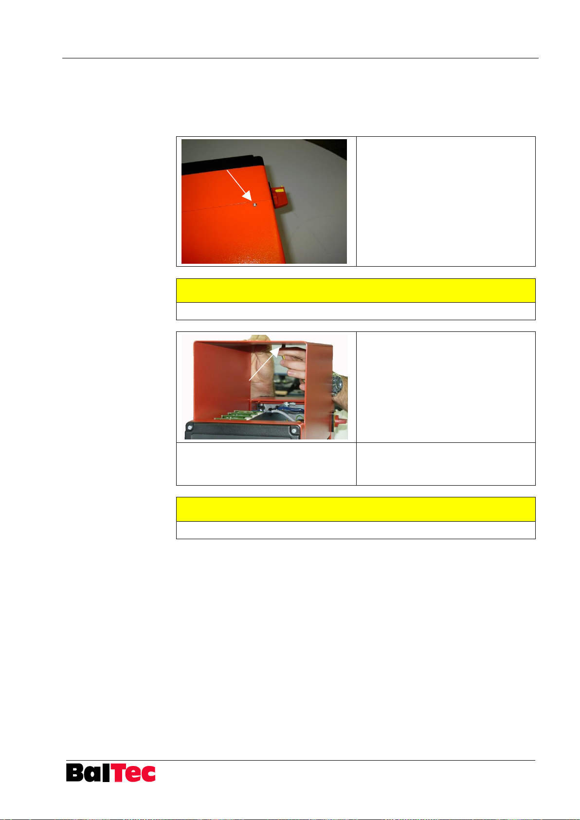
Process-Controller HPP - 25 Maintenance and repair work
803699.017/ENG
75
Unscrew the 4 TORX screw (T10) of
the cover above
CAUTION
Earth cable is plugged on the cover!
Pull out cover with care and extract
earth cable
Remove cover
Install desired option or replace
module
Assembly takes place in reverse order
CAUTION
Check when assembling, that earth cable is reconnected again!
8.3 Opening the Controller
In normal case the user never needs to open the Controller HPP-25. However, it is
possible that an option is to install or a module is to replace. In this case, the
Controller HPP-25 must be opened as follows:
Page 76

Appendix Process-Controller HPP - 25
76
803699.017/ENG
NOTICE
Texts and abbreviations of following diagrams are listed again, described and
translated into the corresponding language in the table on the same page.
9 Appendix
9.1 Schemata
Page 77
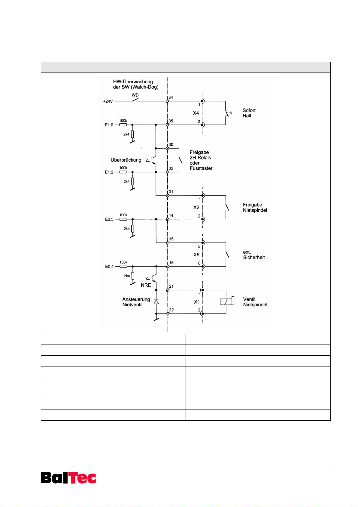
Process-Controller HPP - 25 Appendix
803699.017/ENG
77
WM Nr. 109037080
HW-Überwachung der SW (Watch-Dog)
Hardware monitoring of software (watchdog)
Sofort-Halt
Instant stop
Überbrückung
Bridging
Freigabe 2H-Relais oder Fusstaster
Release two-hand relay or foot switch
Freigabe Nietspindel
Release riveting spindle
ext. Sicherheit
External safety circuit
Ansteuerung Nietventil
Riveting valve activation
Ventil Nietspindel
Riveting spindle valve
9.1.1 Riveting spindle release chain principle diagram
Page 78
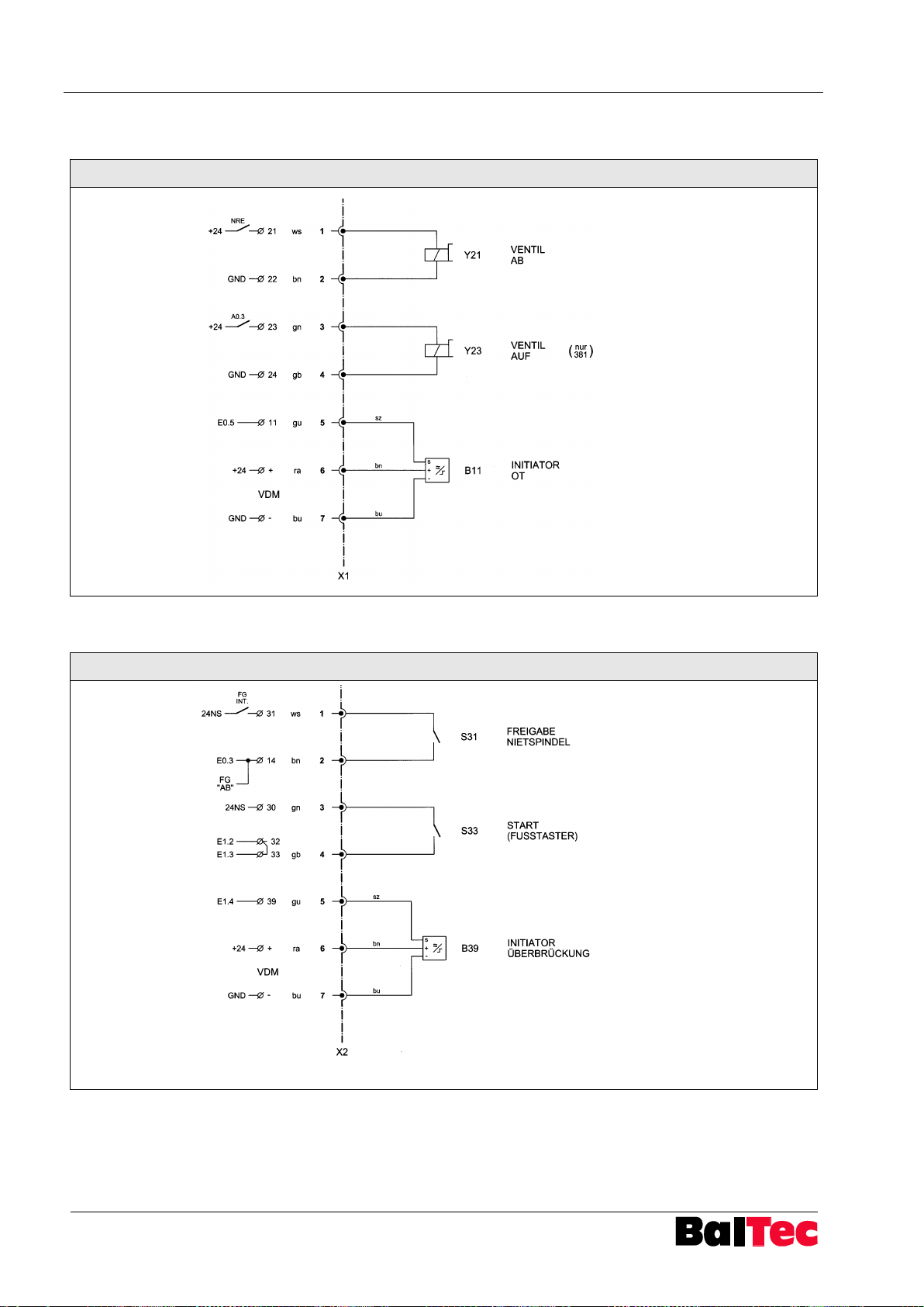
Appendix Process-Controller HPP - 25
78
803699.017/ENG
WM Nr. 109037101
ws = white
Valve DOWN
bn = brown
gn = green
Valve UP (381 only)
gb = yellow
gu = grey
Initiator TDC
ra = pink
bu = blue
VDM = Voltage
Distribution
Module
WM Nr. 109037201a
ws = white
Release riveting spindle
bn = brown
gn = green
Start (Foot switch)
gb = yellow
gu = grey
Bridging initiator
ra = pink
bu = blue
VDM = Voltage
Distribution
Module
9.1.2 Connection diagram plug X1
9.1.3 Connection diagram plug X2, Foot switch
Page 79
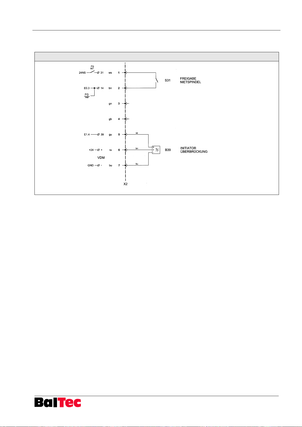
Process-Controller HPP - 25 Appendix
803699.017/ENG
79
WM Nr. 109037202
ws = white
Release riveting spindle
bn = brown
gn = green
gb = yellow
gu = grey
Bridging initiator
ra = pink
bu = blue
VDM = Voltage
Distribution
Module
9.1.4 Connection diagram plug X2, Two-hand operating unit relay
Page 80
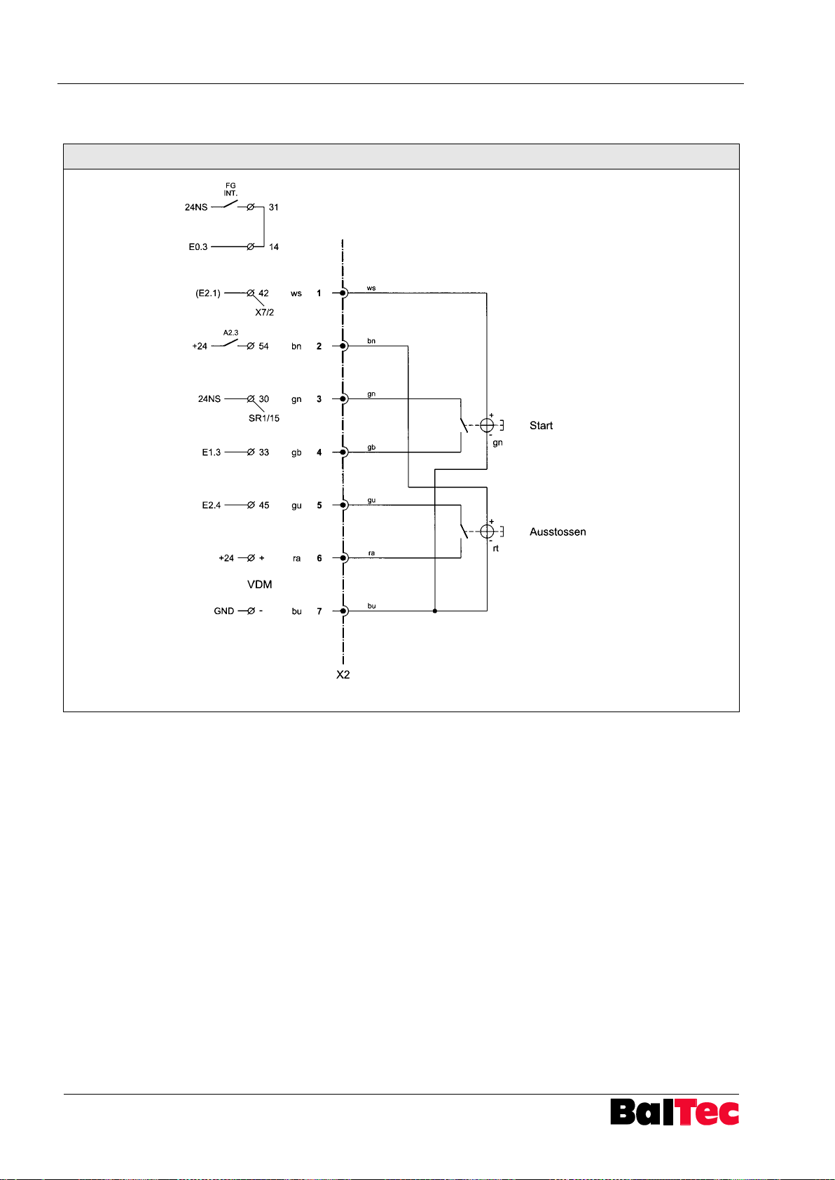
Appendix Process-Controller HPP - 25
80
803699.017/ENG
WM Nr. 109037211
ws = white
bn = brown
gn = green
gb = yellow
gu = grey
ra = pink
Start
bu = blue
VDM = Voltage
Distribution
Module
Ejection
9.1.5 Connection diagram plug X2 HST (Manual sliding table)
Page 81
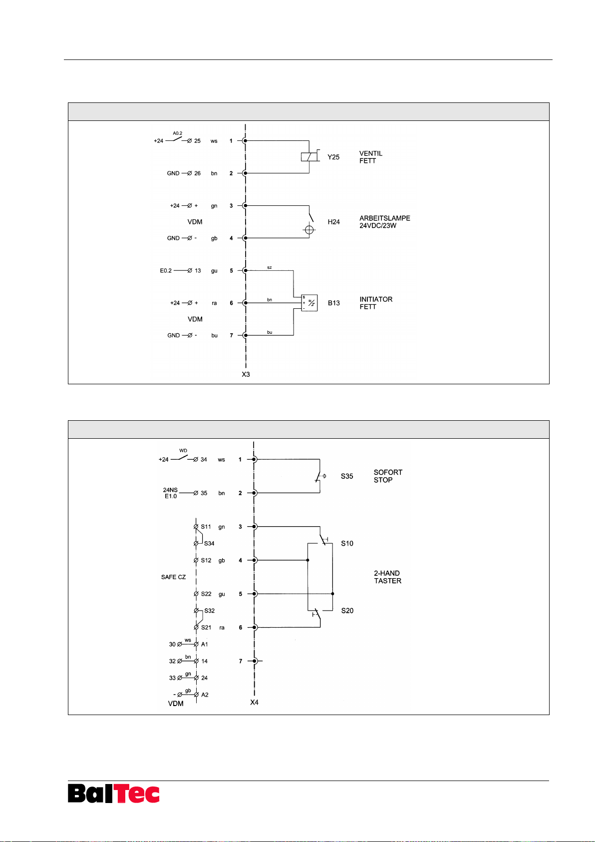
Process-Controller HPP - 25 Appendix
803699.017/ENG
81
WM Nr. 109037301
ws = white
Grease valve
bn = brown
gn = green
Working lamp
gb = yellow
gu = grey
Grease initiator
ra = pink
bu = blue
VDM = Voltage
Distribution
Module
WM Nr. 109037401
ws = white
Instant stop
bn = brown
gn = green
gb = yellow
gu = grey
Two-hand operating unit
ra = pink
VDM = Voltage
Distribution
Module
9.1.6 Connection diagram plug X3
9.1.7 Connection diagram plug X4
Page 82
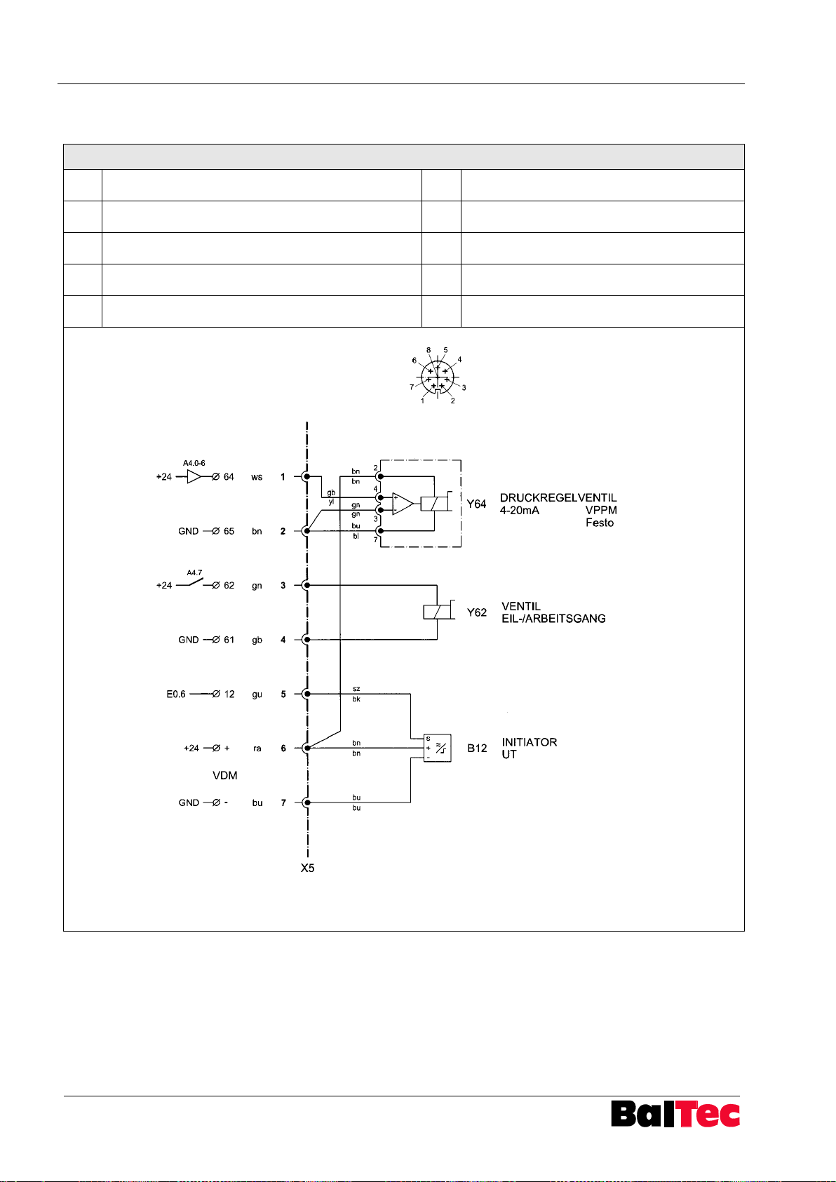
Appendix Process-Controller HPP - 25
82
803699.017/ENG
WM Nr. 109037504
Pin
Signal
Pin
Signal
1
Digital input D1
5
Digital input D2
2
DC +24V supply voltage
6
Analog output X
3
Analog input W-
7
DC 0V or GND
4
Analog input W+
8
Digital output D3
ws = white
Pressure control
valve VPPM
bn = brown
gn = green
Rapid
speed/working
speed valve
gb =
yellow
gu = grey
Initiator BDC
ra = pink
bu = blue
VDM =
Voltage
Distribution
Module
9.1.8 Connection diagram plug X5, pressure control valve
Page 83
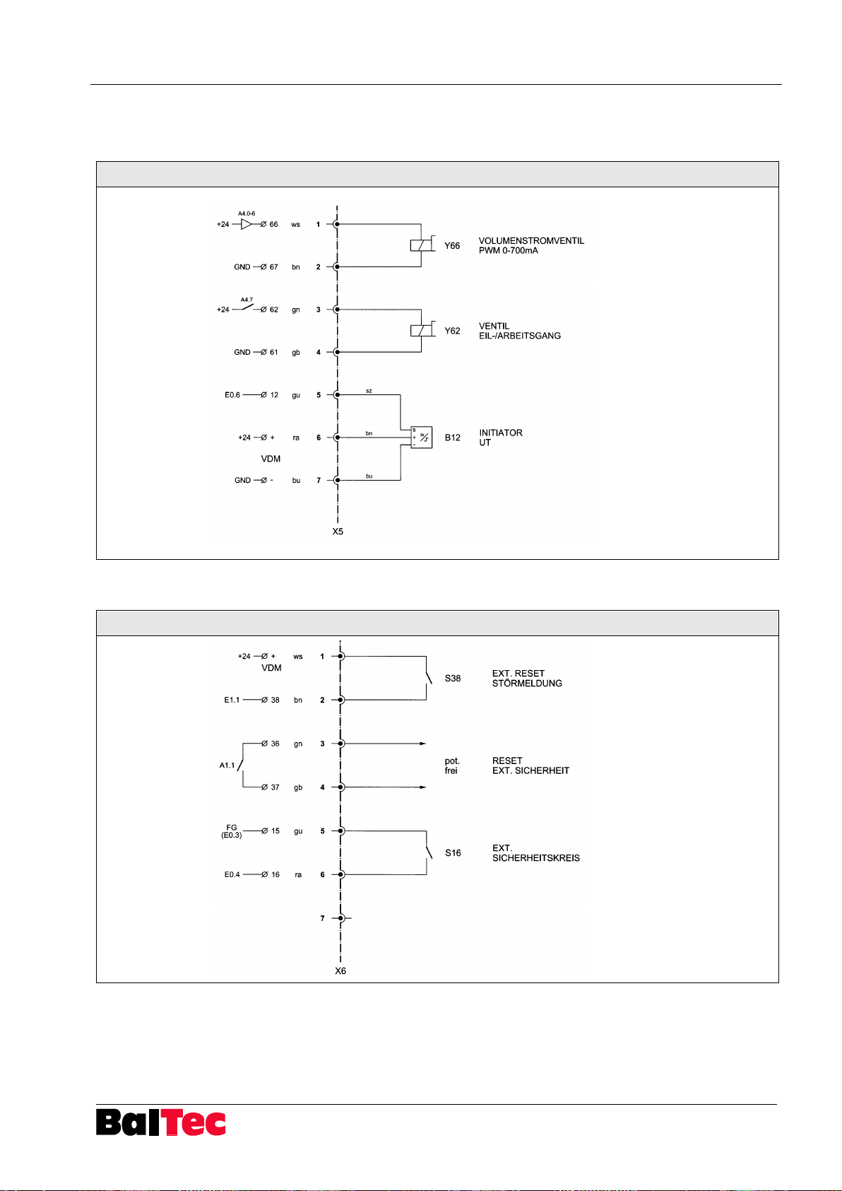
Process-Controller HPP - 25 Appendix
803699.017/ENG
83
WM Nr. 109037501
ws = white
Volume flow regulating
valve
bn = brown
gn = green
Rapid speed/working
speed valve
gb = yellow
gu = grey
Initiator BDC
ra = pink
bu = blue
VDM = Voltage
Distribution
Module
WM Nr. 109037601
ws = white
External alert reset
bn = brown
gn = green
External safety reset
potential-free
gb = yellow
gu = grey
External safety circuit
ra = pink
VDM = Voltage
Distribution
Module
9.1.9 Connection diagram plug X5, Volume flow regulating valve, Rapid speed/working speed
valve, Initiator BDC
9.1.10 Connection diagram plug X6
Page 84
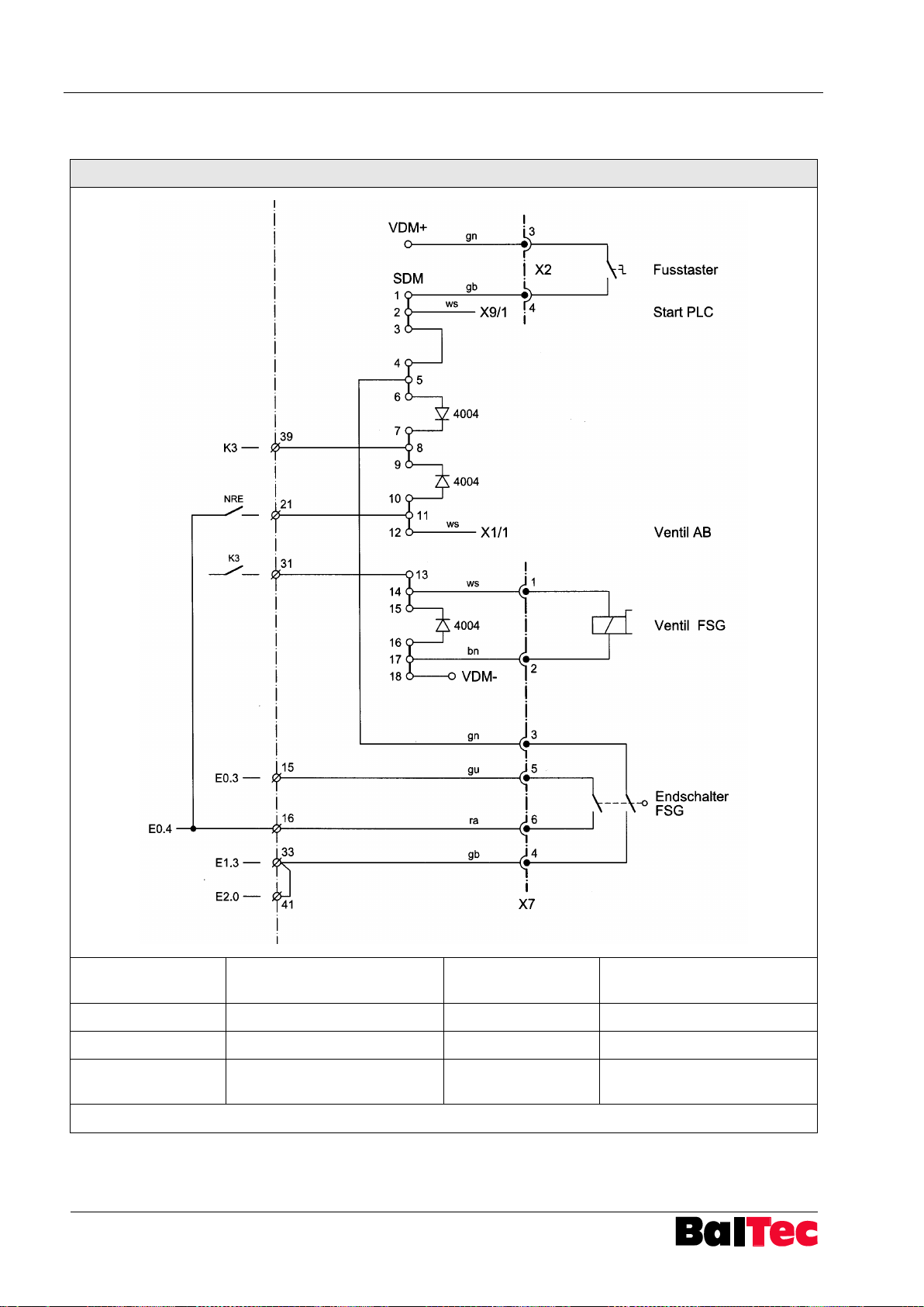
Appendix Process-Controller HPP - 25
84
803699.017/ENG
WM Nr. 109037702
Fusstaster
Foot switch
Endschalter FSG
Limit switch finger guard
device
Start PLC
Start PLC (option)
VDM
Voltage distribution module
Ventil AB
Valve down
SDM
Signal distribution module
Ventil FSG
Valve finger guard device
NRE
Not riveting enable (release
riveting spindle valve)
gn = green; gb = yellow; ws = white; bn = brown; gu = grey; ra = pink
9.1.11 Connection diagram plug X7, finger guard device
Page 85
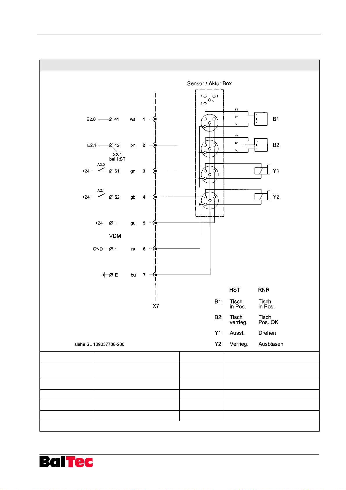
Process-Controller HPP - 25 Appendix
803699.017/ENG
85
WM Nr. 109037708
Sensor/Aktor Box
Sensor/Actor Box
VDM
Voltage Distribution Module
HST
Manual sliding table
RNR
Radial riveting machine with
pneumatic rotary indexing table
Tisch in Pos.
Table in position
Tisch verrieg.
Lock table
Ausst.
Ejection
Tisch Pos. OK
Table position OK
Drehen
Rotating
Verrieg.
Locking
Ausblasen
Blowing out
gn = green; gb = yellow; ws = white; bn = brown; gu = grey; ra = pink; bu = blue; sz = black
9.1.12 Connection diagram plug X7 HST/RNR
Page 86
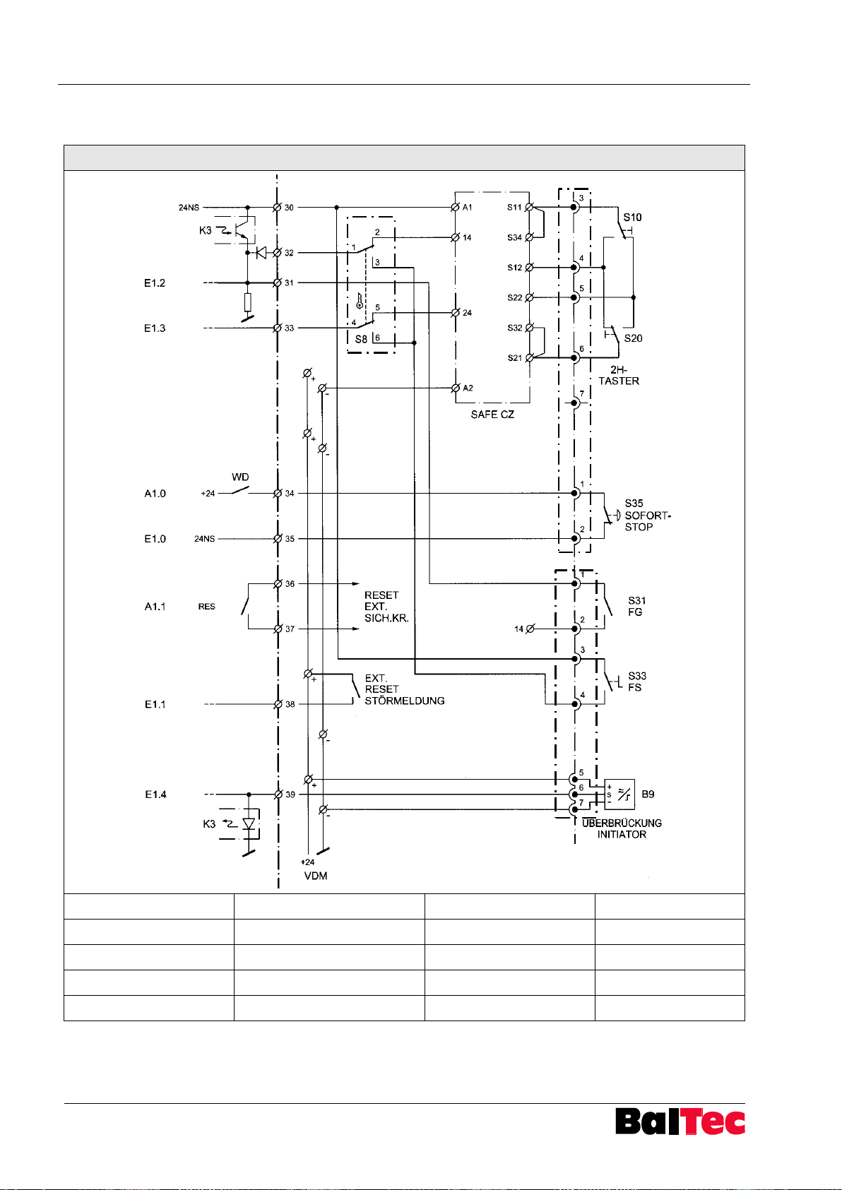
Appendix Process-Controller HPP - 25
86
803699.017/ENG
WM Nr. 107053735
Schlüssel-Schalter
Key switch
Sofort-Stop
Instant stop
Reset ext. Sich.Kr.
Reset external safety circuit
FG
Release
Ext. Reset Störmeldung
External alert reset
FS
Foot switch
VDM
Voltage distribution module
Überbrückung Initiator
Bridging initiator
2H-Taster
Two-hand operating unit
X4
X2
SchlüsselSchalter X8
9.1.13 Connection diagram plug X8, key switch two-hand operating unit/foot switch
Page 87
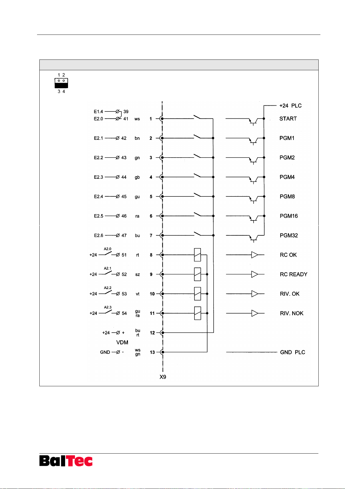
Process-Controller HPP - 25 Appendix
803699.017/ENG
87
WM Nr. 109037901a
X3
ws = white
bn = brown
gn = green
gb = yellow
gu = grey
ra = pink
bu = blue
rt = red
sz = black
vt = violet
gu/ra =
grey/pink
bu/rt = blue/red
ws/gn =
white/green
VDM = Voltage
Distribution
Module
9.1.14 Connection diagram plug X9
Page 88
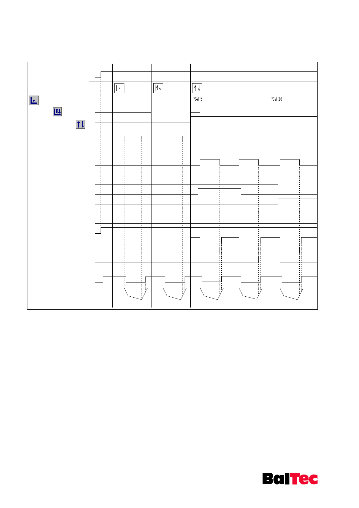
Appendix Process-Controller HPP - 25
88
803699.017/ENG
Control
ON
OFF
Selection operation mode
on touch screen
Start foot switch
(Kl.33)
(E1.3)
PLC Interface
Start PLC (E2.0)
PGM 1 (E2.1)
PGM 1 (E2.2)
PGM 1 (E2.3)
PGM 1 (E2.4)
PGM 1 (E2.5)
PGM 1 (E2.6)
RC OK (A2.0)
RC Ready (A2.1)
RIV OK (A2.2)
RIV NOK (A2.3)
Sensor TDC (E0.5)
Movement riveting
spindle
9.1.15 PLC-Interface Step sequence diagram
Precondition for operation with PLC interface (connector X9): Parameter 80 = 1
Start PLC only in operation mode Cycle.
If operation mode Setup or Correction have to start also by PLC, a bridge must be
set between E2.0-E1.3 (terminal 41 – 33).
If no program is selected in operation mode Cycle (PGM 0), the riveting program
can be selected on the touch screen.
Page 89
Process-Controller HPP - 25 Appendix
803699.017/ENG
89
pin X11
Signal
1
V+ (12V)
2
OUT
3
0V / GND
pin X12
Signal
1
V+ (12V)
2
OUT
3
0V / GND
pin X13
Signal
1
A+ 2 A - 3 B+ 4 B - 5 0V / GND
6
5V
9.1.16 Connection diagram X11, X12, X13, X14
9.1.16.1 Lower pressure X11
9.1.16.2 Upper pressure X12
9.1.16.3 Path measurement X13
Page 90
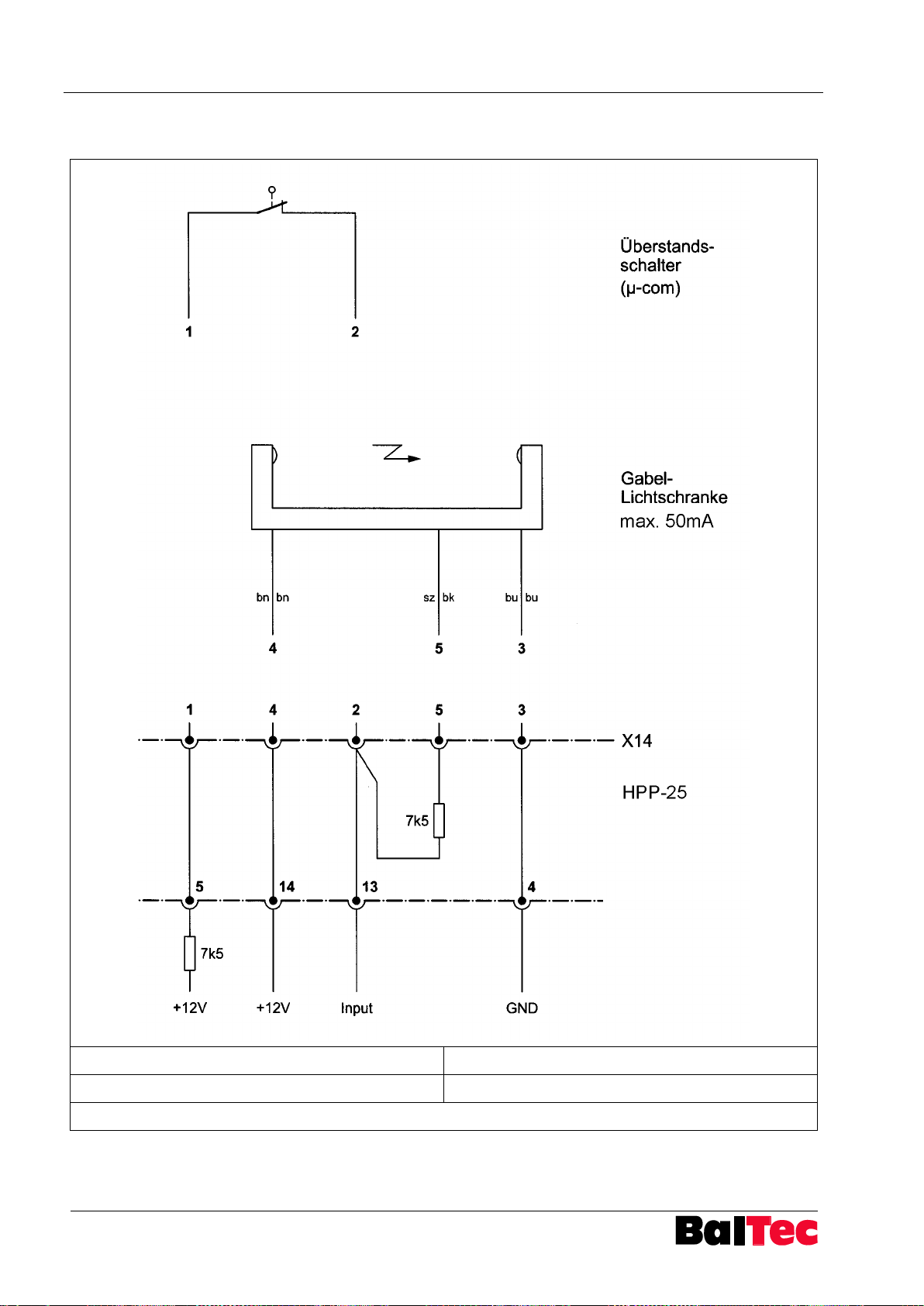
Appendix Process-Controller HPP - 25
90
803699.017/ENG
Überstandsschalter (µ-com)
Rivet projection switch (µ-com)
Gabel-Lichtschranke
Forked light barrier
bn = brown; sz = black; bu = blue
9.1.16.4 Switch NHE X14
Page 91
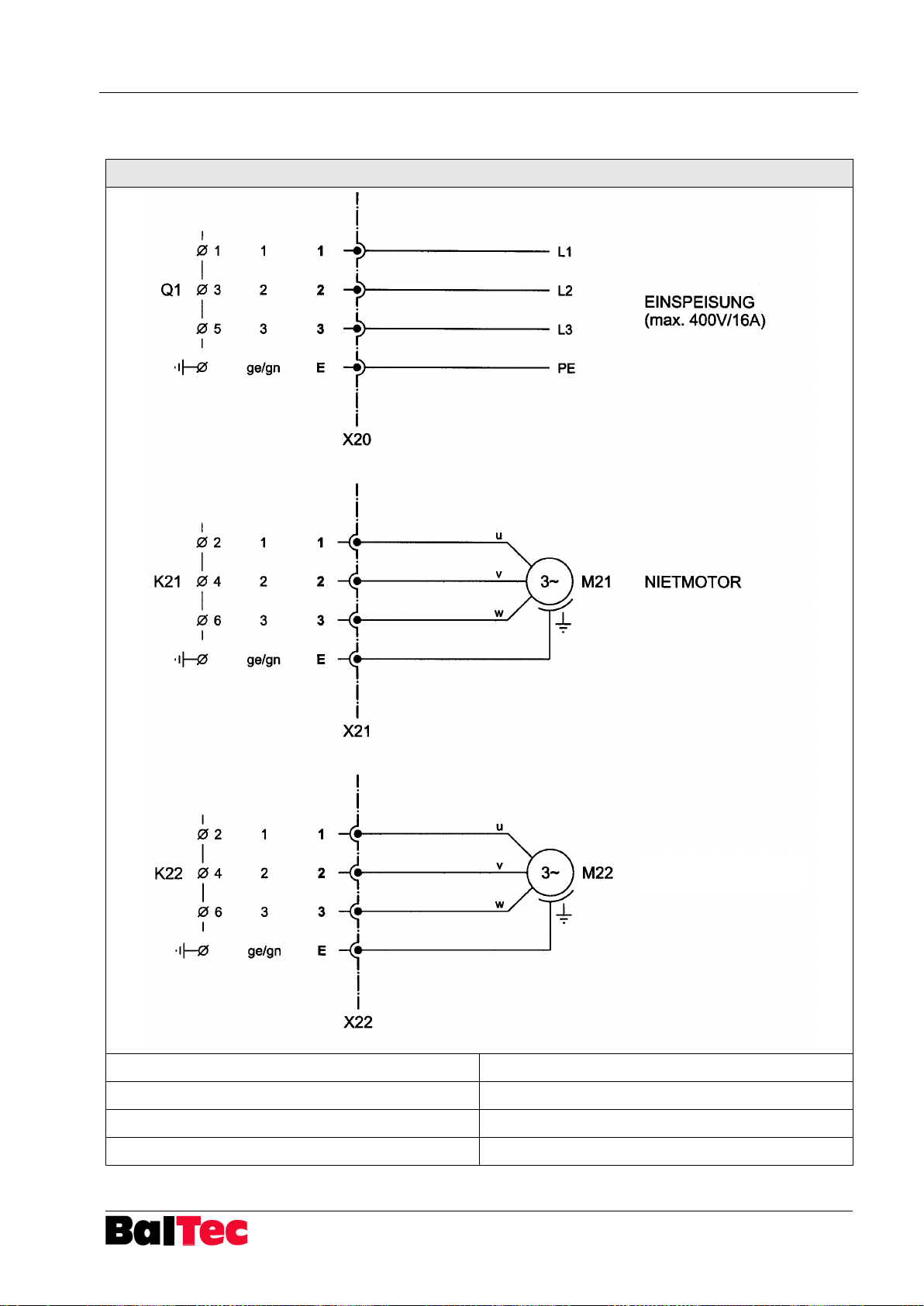
Process-Controller HPP - 25 Appendix
803699.017/ENG
91
WM Nr. 109037020
Einspeisung
Power supply
Nietmotor
Riveting motor
Motor 2
Motor 2
ge/gn
yellow/green
MOTOR 2
9.1.17 Connection diagram plug X20, X21, X22
Page 92
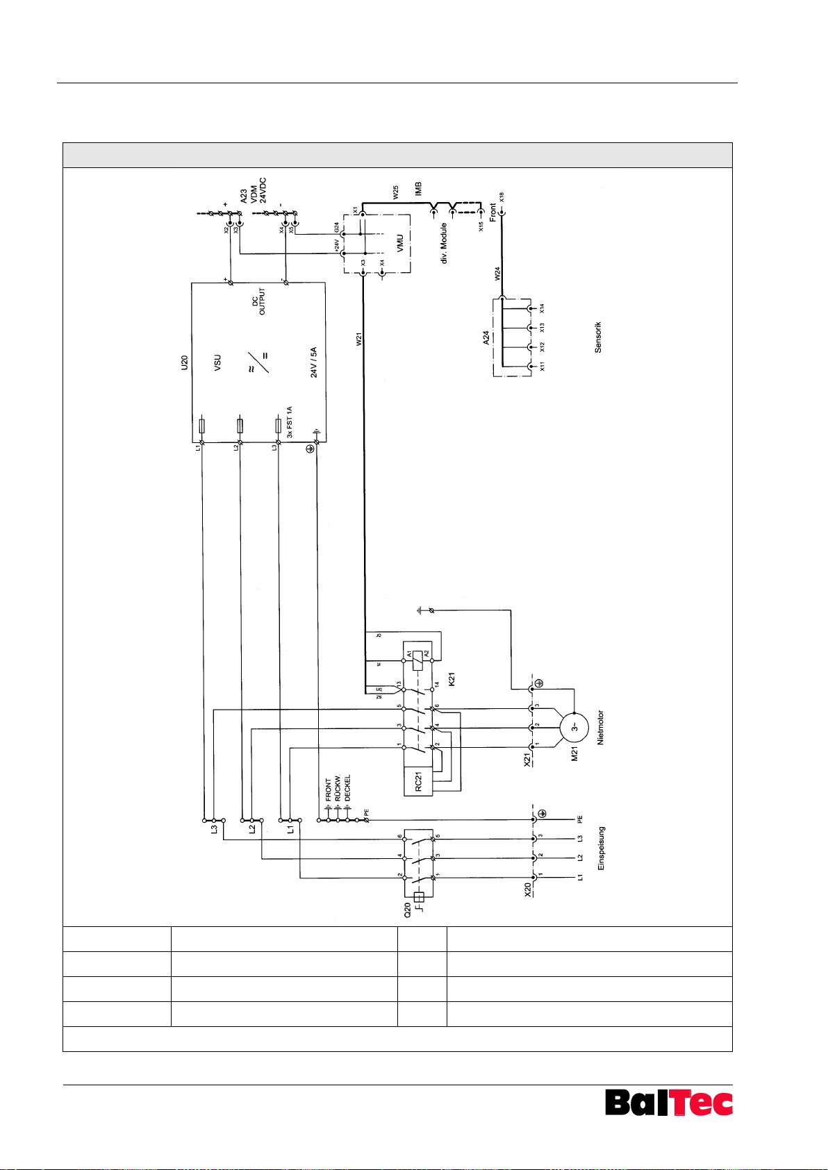
Appendix Process-Controller HPP - 25
92
803699.017/ENG
WM Nr. 109067430
Einspeisung
Supply
IMB
Ribbon cable
Nietmotor
Riveting motor
VMU
Valve and motor unit
Sensorik
Sensor system
VSU
Voltage supply unit
div. Module
Diverse modules
VDM
Voltage distribution module
or = orange; rt = red; bn = brown; sz = black
9.1.18 Wiring diagram Supply, Motors HPP-25 pneumatic
Page 93
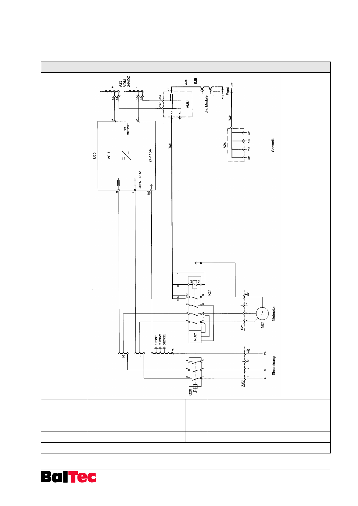
Process-Controller HPP - 25 Appendix
803699.017/ENG
93
WM Nr. 109067410
Einspeisung
Supply
IMB
Ribbon cable
Nietmotor
Riveting motor
VMU
Valve and motor unit
Sensorik
Sensor system
VSU
Voltage supply unit
div. Module
Diverse modules
VDM
Voltage distribution module
or = orange; rt = red; bn = brown; sz = black
9.1.19 Wiring diagram Supply, Motors monophase HPP-25 pneumatic
Page 94
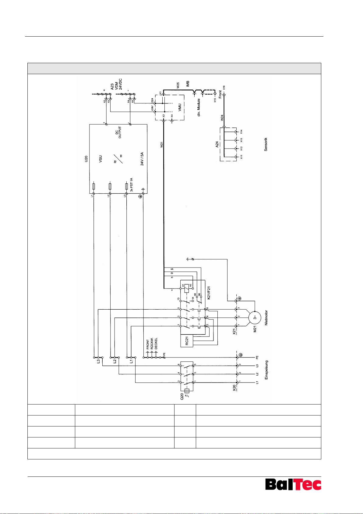
Appendix Process-Controller HPP - 25
94
803699.017/ENG
WM Nr. 109067431
Einspeisung
Supply
IMB
Ribbon cable
Nietmotor
Riveting motor
VMU
Valve and motor unit
Sensorik
Sensor system
VSU
Voltage supply unit
div. Module
Diverse modules
VDM
Voltage distribution module
or = orange; rt = red; bn = brown; sz = black
9.1.20 Wiring diagram Supply, Motors with thermal overload HPP-25 pneumatic
Page 95
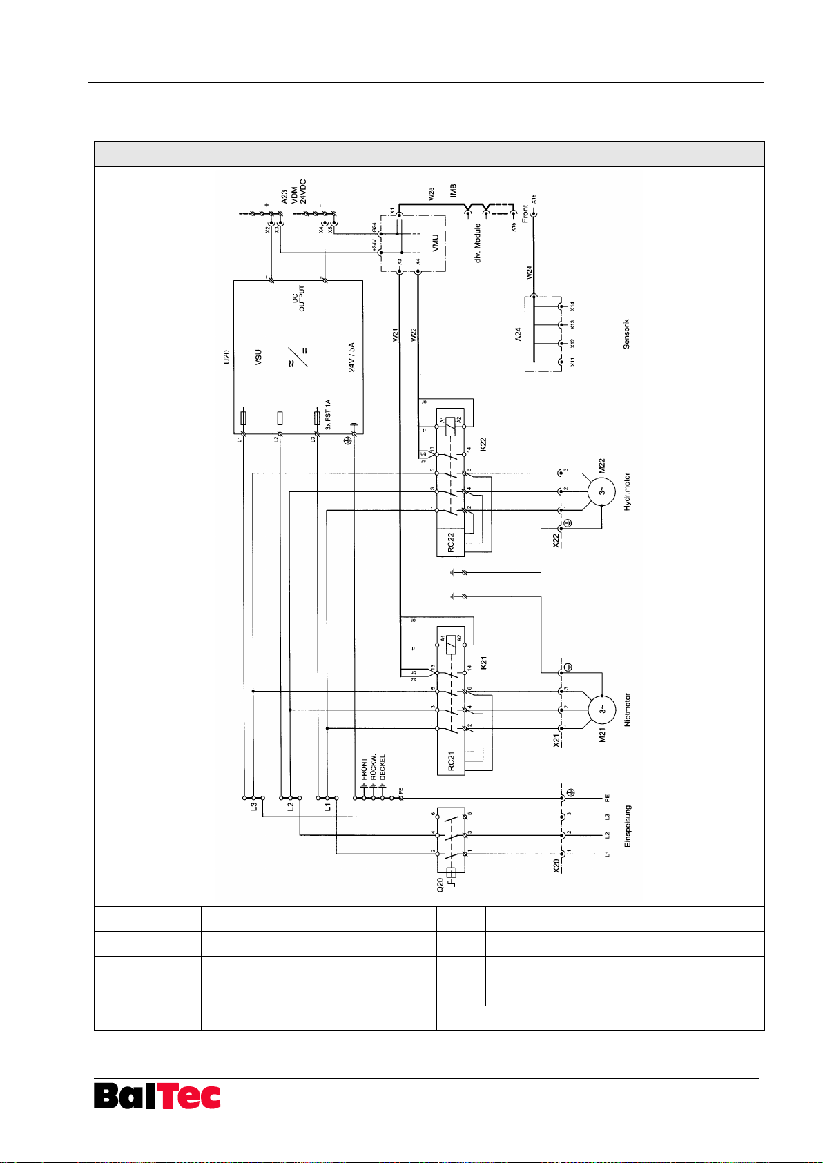
Process-Controller HPP - 25 Appendix
803699.017/ENG
95
WM Nr. 109067530
Einspeisung
Supply
IMB
Ribbon cable
Nietmotor
Riveting motor
VMU
Valve and motor unit
Hydr. motor
Hydraulic motor
VSU
Voltage supply unit
Sensorik
Sensor system
VDM
Voltage distribution module
div. Module
Diverse modules
or = orange; rt = red; bn = brown; sz = black
9.1.21 Wiring diagram Supply, Motors HPP-25 hydraulic
Page 96
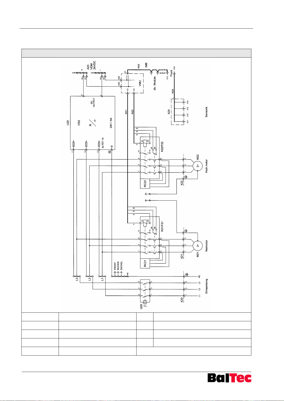
Appendix Process-Controller HPP - 25
96
803699.017/ENG
WM Nr. 109067531
Einspeisung
Supply
IMB
Ribbon cable
Nietmotor
Riveting motor
VMU
Valve and motor unit
Hydr. motor
Hydraulic motor
VSU
Voltage supply unit
Sensorik
Sensor system
VDM
Voltage distribution module
div. Module
Diverse modules
or = orange; rt = red; bn = brown; sz = black
9.1.22 Wiring diagram Supply, Motors with thermal overload HPP-25 hydraulic
Page 97
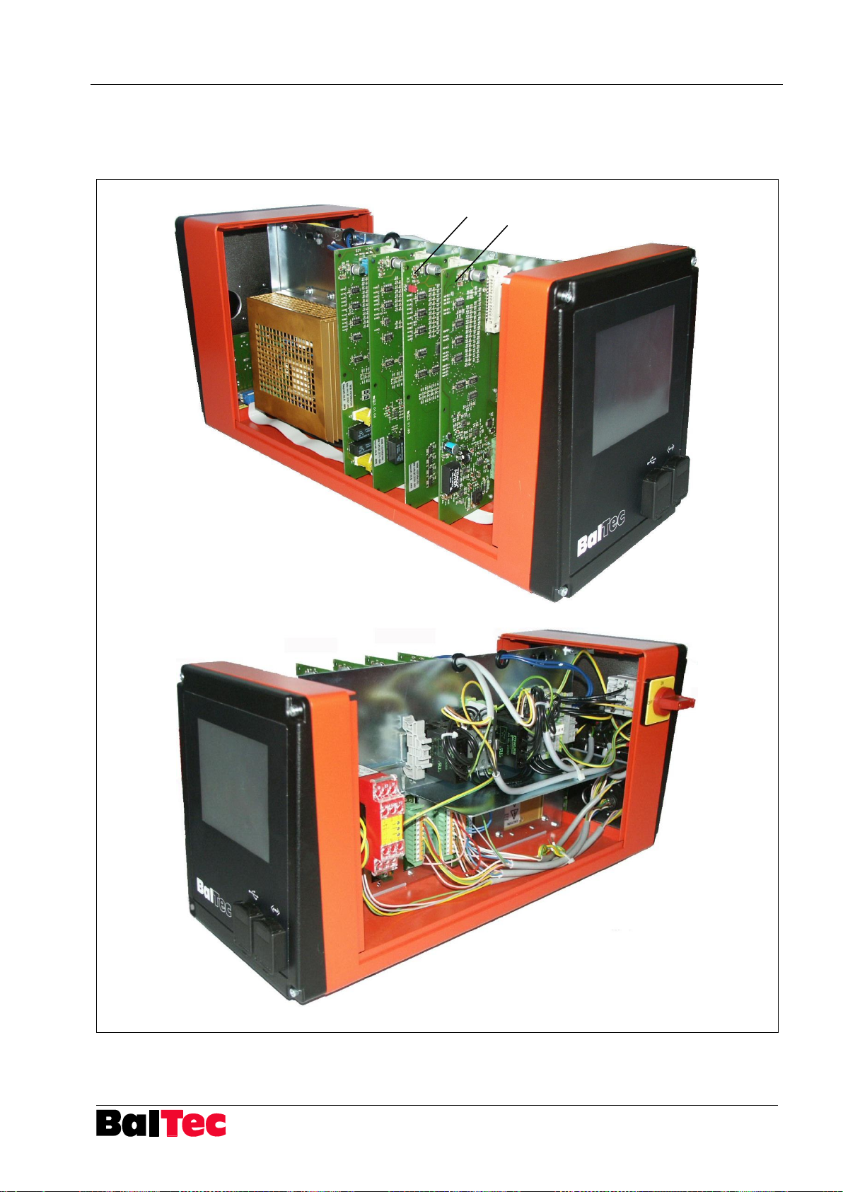
Process-Controller HPP - 25 Appendix
803699.017/ENG
97
19
16
9.2 Spare parts lists
9.2.1 Process-Controller HPP-25, 826337-d
Page 98
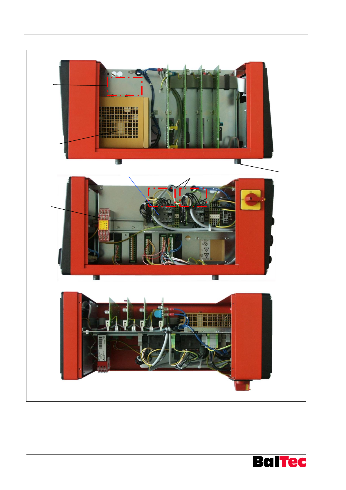
Appendix Process-Controller HPP - 25
98
803699.017/ENG
1, 2
13
9
23-30
10,11
35, 36, 37
Page 99

Process-Controller HPP - 25 Appendix
803699.017/ENG
99
20, 21
7
Reserve
8 5 6
17
18
14,15
3,4
12
Page 100
Appendix Process-Controller HPP - 25
100
803699.017/ENG
Pos.
No.
Part name
Part no.
Remarks
1 4 Rubber pad
391202
2 4
Screw
341010
In-6kt M4x10 DIN 912-12.9
3 1 Process-Controller HPP-25
530925
pneumatic machines, 380-500V
X9
3 1 Process-Controller HPP-25
530926
pneumatic machines, 380-500V
X4, X6, X9
3 1 Process-Controller HPP-25 complete
530929
According to definition sheet
4 1 Base Process-Controller HPP-25
530930
5 2
Cable plug X1, X3
520252
7-pole, male
6 1 Cable socket X2
520276
7-pole, female
7 1 Cable socket X20
520619
4-pole (3+PE), female
8 1 Cable plug X21, X22
520618
4-pole (3+PE), male
9
1
Accessory hydraulic riveting
machine
530931
(contactor, bushing X22)
10 1 Ring core transformer
530985
1x180V, 3x180V, 3x345V, 150VA
11 1 Ring core transformer
530986
3x575V, 150VA
12 1 Rear panel
530933
equipped with key switch
13 1 Two-hand relay
524708
RIESE SAFE CZ 24 V DC
13 1 Mounting angle for two-hand relay
530934
HS35
14 1 Connection X4 (bushing)
530935
Two-hand operating unit with/without
Emergency stop
15 1 Connection X4 (bushing)
530936
Emergency stop
16 1 PVM module
530963
17 1 Connection X5 (bushing)
530937
Analogue output for pressure control
valve, initiator BDC
18 1 Connection X6 (bushing)
530939
External safety, Alert reset
18 1 Connection X7
530943
FSG (finger guard device)
18 1 Connection X7
530942.xx
for customer-specific functions
19 1 PLC-Interface
530962
20 1 Connection PLC-Interface
530940
incl. bushing X9 and cable set
21 1 Cable plug 13-pole X9
530941
incl. 5m cable, wired on plug
 Loading...