

Page 1
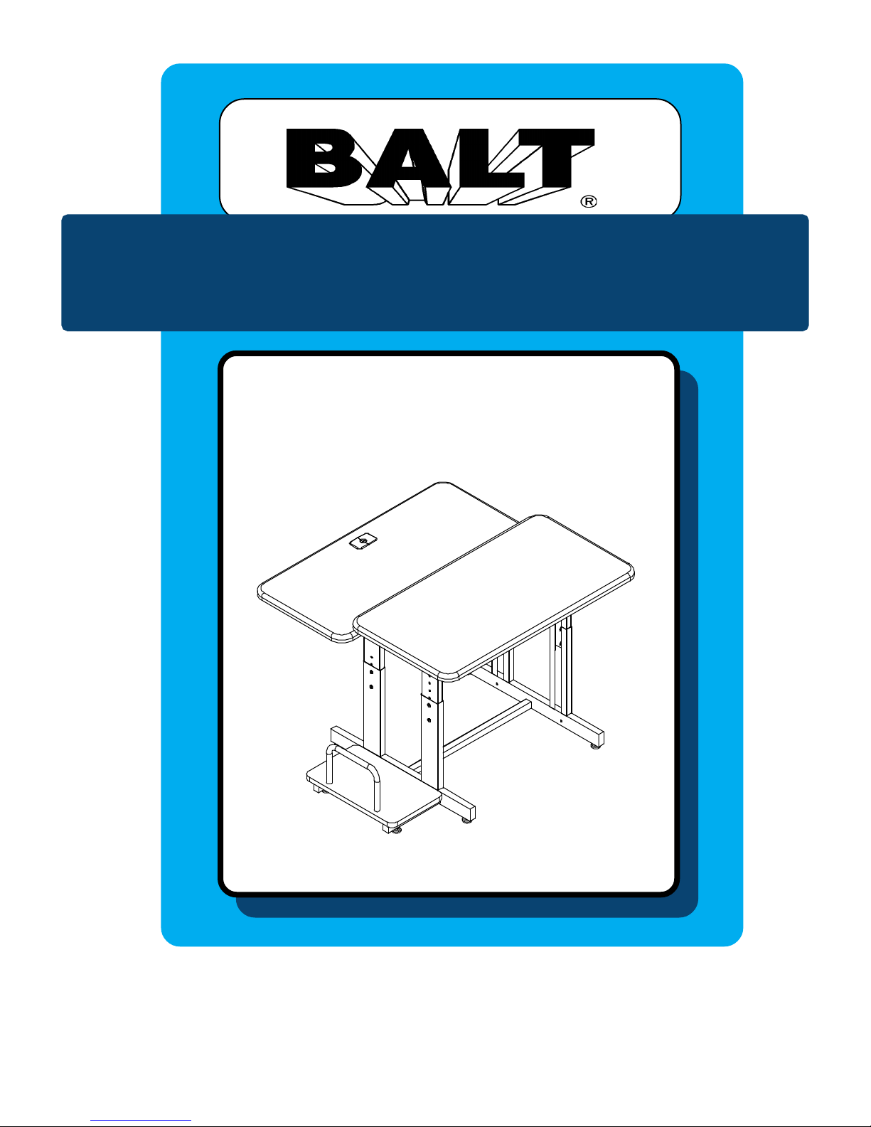
Split-Level-36
T ask T able
Assembly Instructions
1
Page 2
WOW
Split-Level-36
Task T able
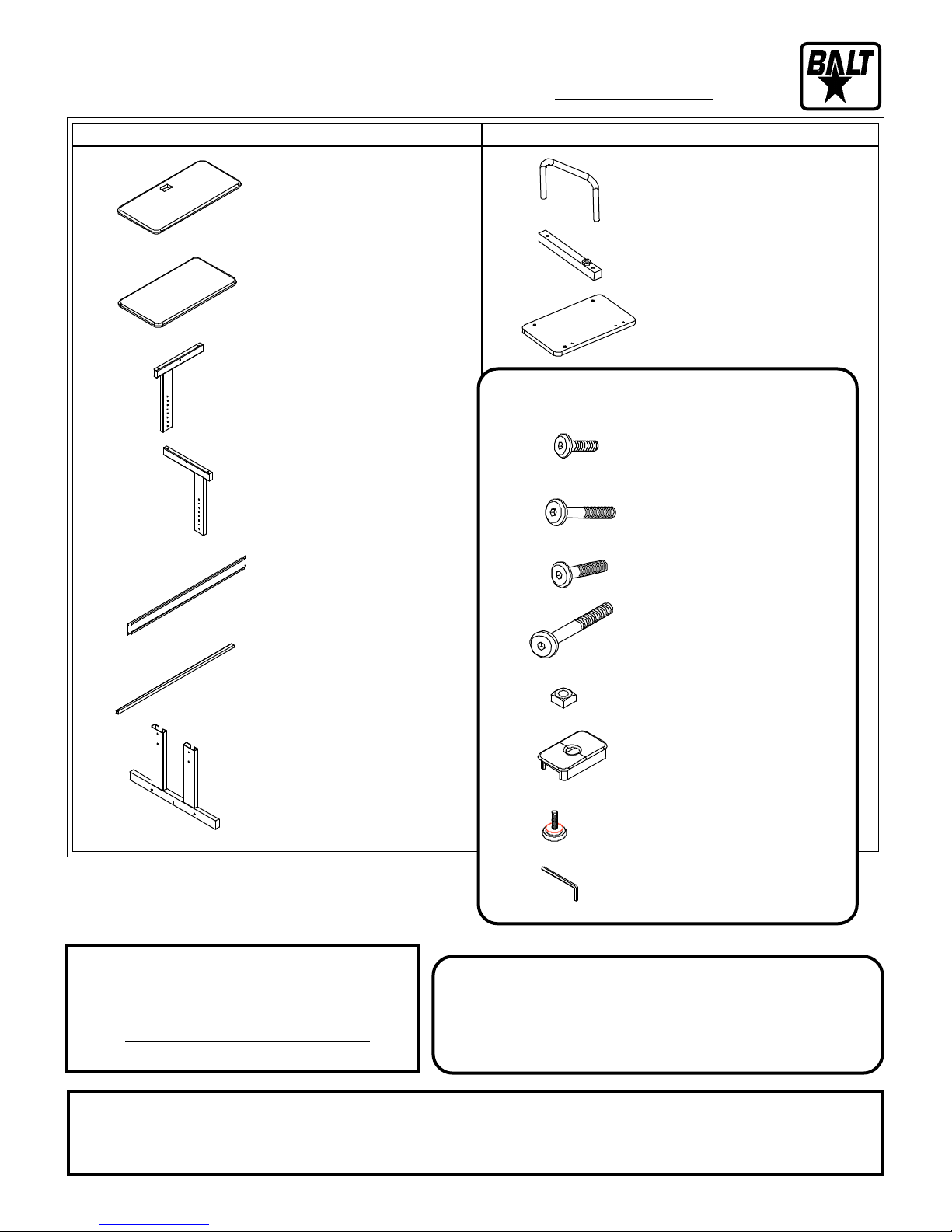
Part Drawing Description Qty Part Drawing Description Qty
P1 Monitor Platform 1 EA
P2 Keyboard Platform 1 EA
P3 Upper Insert 2 EA
Left Front & Right Back
P4 Upper Insert 2 EA
Right Front & Left Back
P8 CPU Rail 1 EA
P9 CPU Foot 2 EA
P10 CPU Platform 1 EA
Hardware List
A 9/16”Socket Screw 16 EA
A1 1-7/8” Socket Screw 10 EA
P5 Stability Panel 2 EA
P6 Crossbrace 3 EA
P7 Leg Receiver 2 EA
We recommend that you assemble this
unit on a table.
T ools required: Adjustable Crescent Wrench
Missing Parts or UPS Damaged Parts
For Y our Convenience you can
EMAIL us at
24HOURS 7 DAYS A WEEK
A2 1-1/2” Socket Screw 4 EA
B 2-3/8” Socket Screw 8 EA
C Square Nut 8 EA
E Plastic Grommet 1 EA
F Glide 6 EA
G Allen Wrench 1 EA
Should you require assistance during assembly,
please call our Customer Service Department
Monday - Friday 8 a.m. - 5 p.m.
Central Standard Time
1-800-749-2258
Do not use unless all screws are tight. At least every six months, check all screws to be sure
they are tight. If parts are missing, broken, damaged, or worn, stop use of the product
until repairs are made by your dealer using factory authorized parts.
2
Page 3
Split-Level-36
Assembly Diagram
R
EAD THROUGH INSTRUCTIONS FROM BEGINNING
END
TO
1.)
BEFORE
Identify and Separate all the Parts
and Hardware.
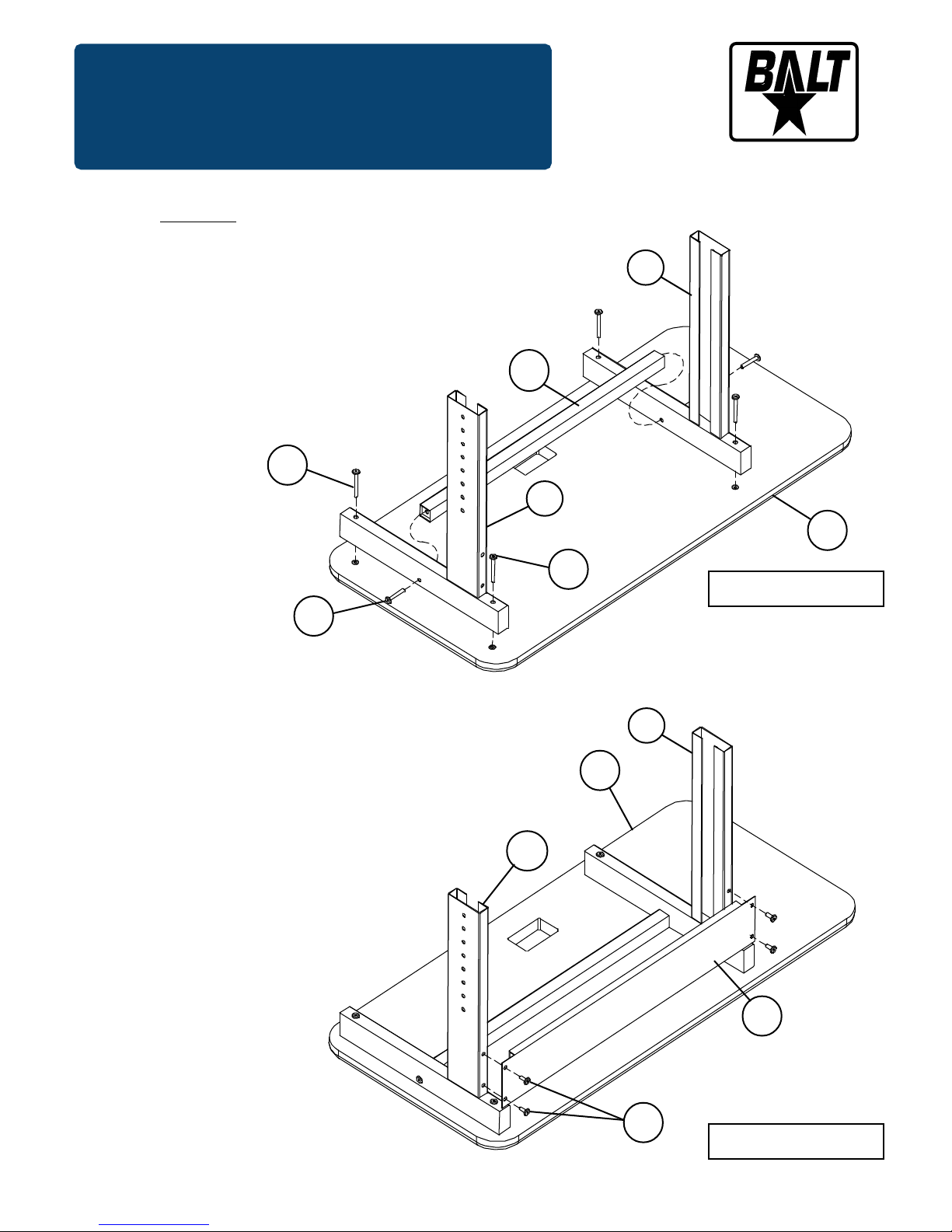
Place the Monitor Platform (P1) with the
2.)
insert nuts facing up. Attach 1 each
Upper Insert (P3) and 1 each Upper Insert
(P4) using 4 each (B) screws.
(Finger tighten only)
ST ARTING TO ASSEMBLE UNIT
B
.
P4
P6
P3
P-1
A1
3.)
Attach Crossbrace (P6)
between the Upper Inserts
(P3 & P4) using 2 Screws (A1)
as shown in illustration #1.
Attach Stability Panel (P5) to the
4.)
Upper Inserts (P3 & P4) using 4
Screws ( A) as shown in
illustration #2.
B
Illustration # 1
P4
P1
P3
P5
3
A
Illustration # 2
Page 4
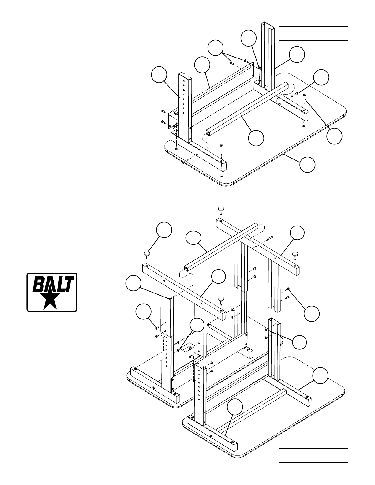
Place the Keyboard Platform (P2) with
5.)
the insert nuts facing up. Attach 1 each
Upper Insert (P3) and 1 each Upper Insert
(P4) using 4 each (B) screws.
(Finger tighten only)
Attach Crossbrace (P6) to the
6.)
Upper Inserts (P3 & P4) using 2
Screws (A1) as shown in
illustration #3.
Attach Stability Panel (P5) to
7.)
the Upper Inserts (P3 & P4)
using 4 Screws ( A) as shown
in illustration #3.
8.)
Slide 2 Leg Receivers (P7) over 2
Upper Inserts (P3) and 2 Upper
Inserts (P4) as shown in illustration
#4. Secure at desired height using 8
each (A) Screws and 8 each (C)
Square nuts (flat side of the nut
should be next to the metal).
P4
Illustration # 3
P3
A1
B
P2
P5
B
A
P6
9.)
Attach 4 each (F) Leveling
Glides to the 2 each Leg
receivers (P7) .
F
P6
P7
10.)
Attach Crossbrace (P6)
between Leg Receivers
(P7) using 2 Screws (A1)
as shown in illustration #4.
(Tighten all the screws at this
time using Allen Wrench (G)).
4
A1
P7
A
C
P4
Illustration # 4
A
C
P3
Page 5
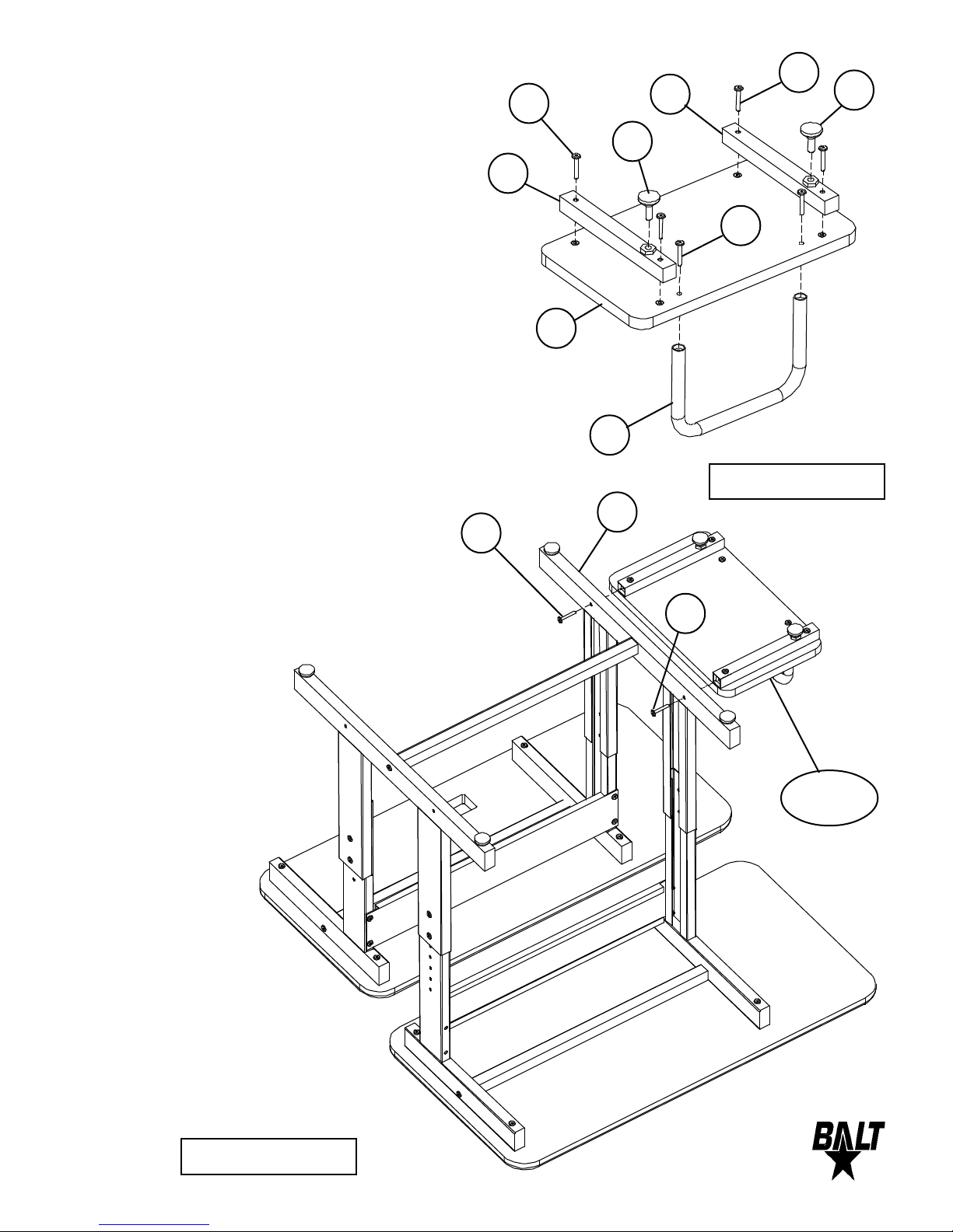
Place the CPU Platform (P10) with the
1 1.)
insert nuts facing up. Attach 2 each CPU
Feet (P9) using 4 each (A2) screws.
(Finger tighten only)
A2
A2
P9
F
F
Attach 1 each CPU Rail (P8) to the CPU
12.)
Platform (P10) using 2 each (A1) screws.
(Finger tighten only)
Attach 2 each Glides (F) to the 2 Feet (P9)
13.)
as shown in illustration #5.
14.)
Attach 1 each CPU Assembly to the outside of Leg Receiver (P7) using 2 Screws
(A1) as shown in illustration #6.
(Tighten all the screws at this time
using Allen Wrench (G)).
P9
A1
P10
P8
Illustration # 5
P7
A1
A1
5
Illustration # 6
CPU
Assembly
Page 6
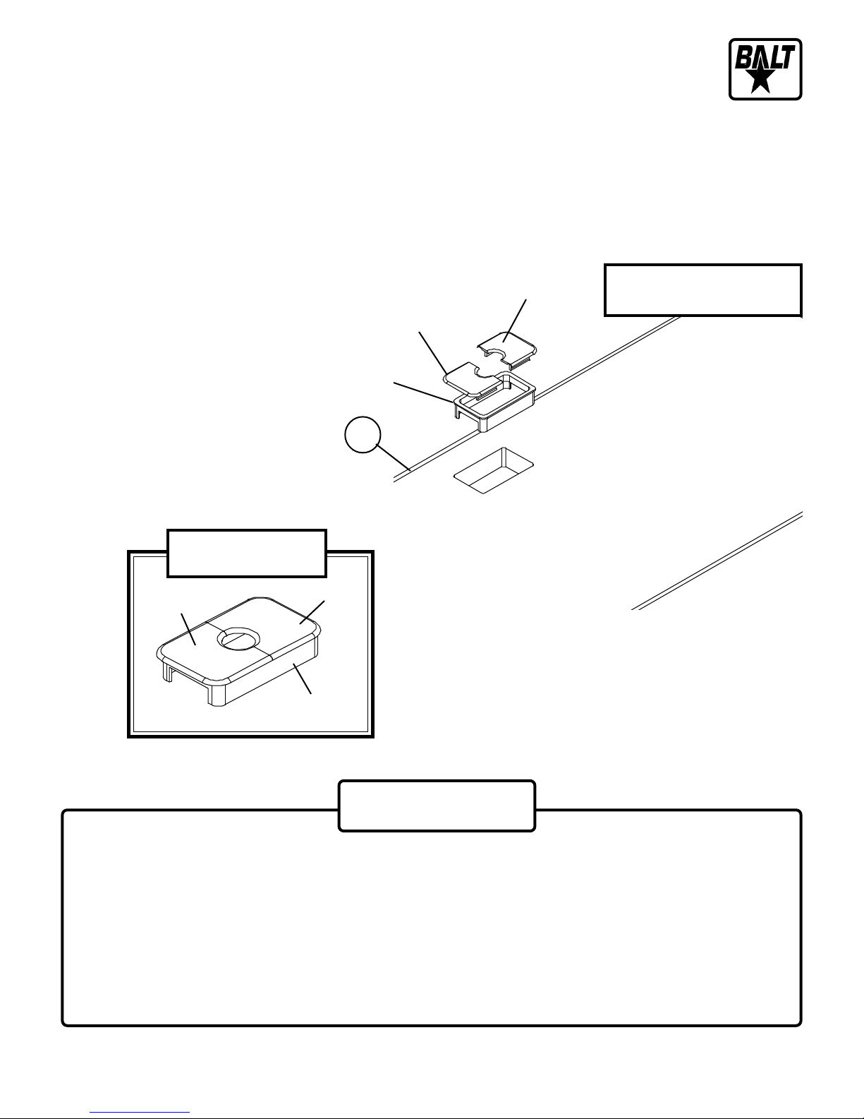
T o install Grommet (E), separate parts
15.)
and press Grommet Sleeve in rectangu-
lar opening in Monitor Platform (P1) as
shown in illustration #6.
Snap 2 plastic Caps over top of Sleeve
as shown in illustration #6.
Cap
Grommet (E)
Sleeve
Cap
P1
Cap
Cap
Grommet(E) installation
Illustration # 6
The Balt product you have purchased is guaranteed against material and workmanship defects. This
guarantee extends 1 year from date of purchase. Should this product fail to function satisfactorily under normal
use due to defect or imperfection, the defective part or product will be replaced. Damage caused by common
carriers during shipment is not included in this guarantee.
This guarantee sets forth all applicable guarantees and remedies. No other warranty, expr essed or
implied shall apply. Failur e to follow instructions found in Important Information Section of Owner
Sheet shall void the guarantee. Consequential or incidental damages and or costs are not refundable.
6
Sleeve
Important
SplitLevel36- 12/30/02
Page 7
Split-Level-36
17
T ask Table
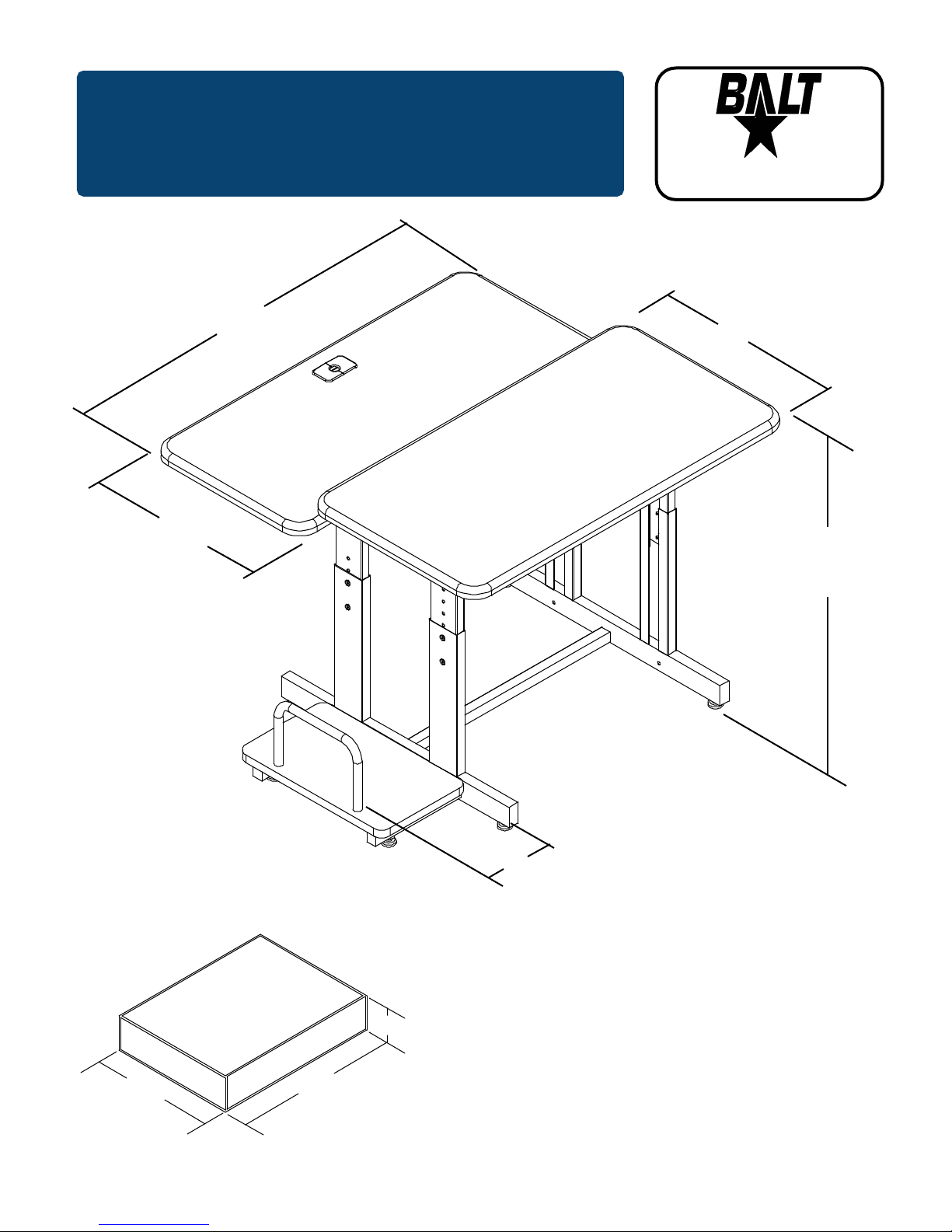
36
For more information
1-800-749-2258
19
Adjustable
Height
25 ½ - 31 ½
Shipping Information
2.8 Cubic Feet
35 lbs.
Carton 1
24”
7
8¾
5½”
36”
splitlevel - 12/07/01
 Loading...