

Page 1
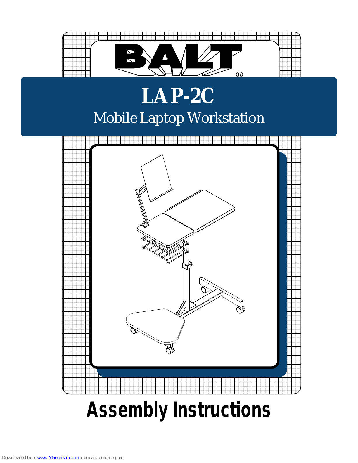
LAP-2C
Mobile Laptop Workstation
Assembly Instructions
Page 2
WOW
LAP-2C
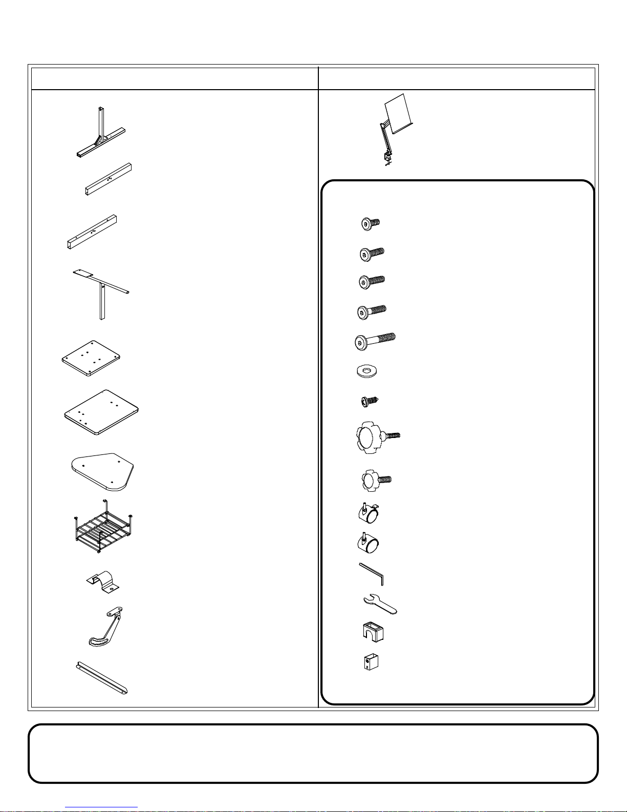
Part Drawing Description Qty
P-1 Lower Receiver 1 EA
P-2 Right Foot 1 EA
P-3 Left Foot 1 EA
P-4 Upper Insert 1 EA
P-5 Accessory Shelf 1 EA
Mobile Laptop W orkstation
Part Drawing Description Qty
P-12 Copyholder 1 E A
Hardware List
A 9/16” Flat Head Screw 11 EA
A1 3/4” Flat Head Screw 4 EA
B 1-5/8” Flat Head Screw 1 EA
C 1-7/8” Flat Head Screw 6 EA
D 2-3/8” Flat Head Screw 2 EA
E Flat Washer 4 EA
P-6 Top Platform 1 EA
P-7 Lower Shelf 1 EA
P-8 Storage Rack 1 EA
P-9 C-Clamp 2 EA
P-10 Tilting Bracket 1 EA
P-11 Security Stop 2 EA
F 1/2” PH Wood Screw 4 EA
G1 Large Knob 1 EA
G2 Small Knob 1 EA
H 2” Locking Caster(for front) 2 EA
J 2” Caster(for Back) 2 EA
K Allen Wrench 1 EA
L Caster Wrench 1 EA
M Plastic Cap 1 EA
N Plastic Sleeve 1 EA
T ools required: Phillips Head Screw Driver
Do not use unless all screws are tight. At least every six months, check all screws to be sure
they are tight. If parts are missing, broken, damaged, or worn, stop use of the product
until repairs are made by your dealer using factory authorized parts.
Page 3
LAP-2C
Assembly Diagram
R
EAD THROUGH INSTRUCTIONS FROM BEGINNING TO
BEFORE
END
1. Identify and Separate all the Parts and Hardware.
ST ARTING TO ASSEMBLE UNIT
.
P-3
C
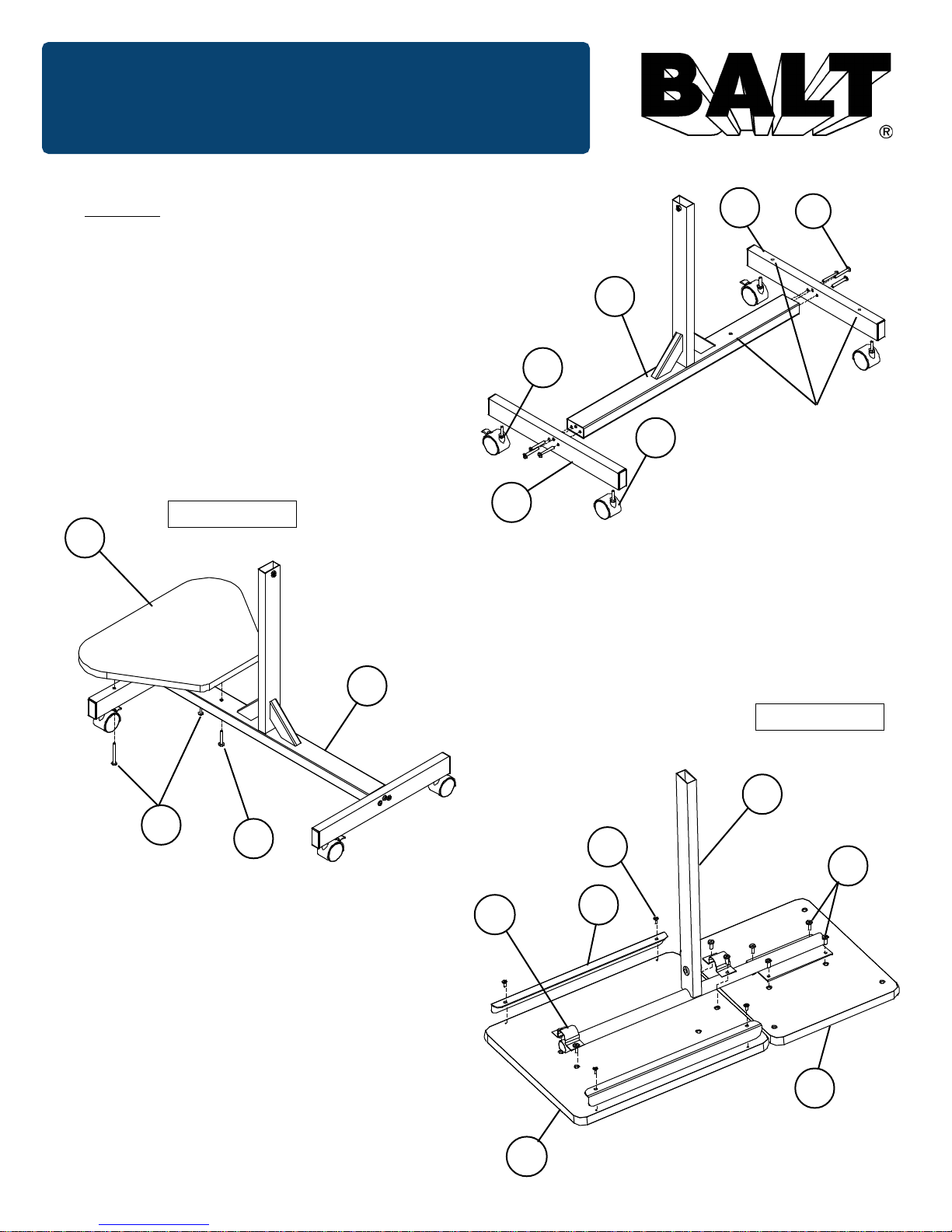
2. Attach Left Foot (P-3) on the end of Lower Reciever
(P-1) with drill hole using 3 Flat Head screws (C).
Attach Right Foot (P-2) on opposite end of Lower
Receiver (P-1) using 3 Flat Head screws (C).
(Do not tighten screws all the way .)
3. Insert 2 Locking Casters (H) and 2 Casters (J)
into Right Foot (P-2) and Left Foot (P-3) as
shown in illustration # 1.
Illustration # 2
P-7
P-1
P-1
H
Drill Hole
J
Attach Left Foot (P-3) on
the end of Lowe Reciever
P-2
(P-1) with drill hole.
4. Attach Lower Printer Shelf (P-7) to the
Lower Receiver (P-1), using 2 Flat Head
screws (D) and 1 Flat Head screw (B) as
shown in illustration # 2.
(Tighten all screws securely)
Illustration # 3
D
B
5. Align T op Platform (P-6) and Accessory Shelf
(P-5) side by side as shown in illustration # 3.
6. Attach Upper Insert (P-4) to the Accessory
Shelf (P-5) using 4 Flat Head Screws (A) as
shown in illustration # 3.
7. Attach T op Platform (P-6) to Upper Insert (P-4)
using 2 C-Clamps (P-9) and 4 Flat Head
screws (A) as shown in illustration # 3.
8. Attach 2 Security Stops (P-1 1) using 4 Wood
screws (F).
P-9
P-4
F
A
P-11
P-5
P-6
Page 4
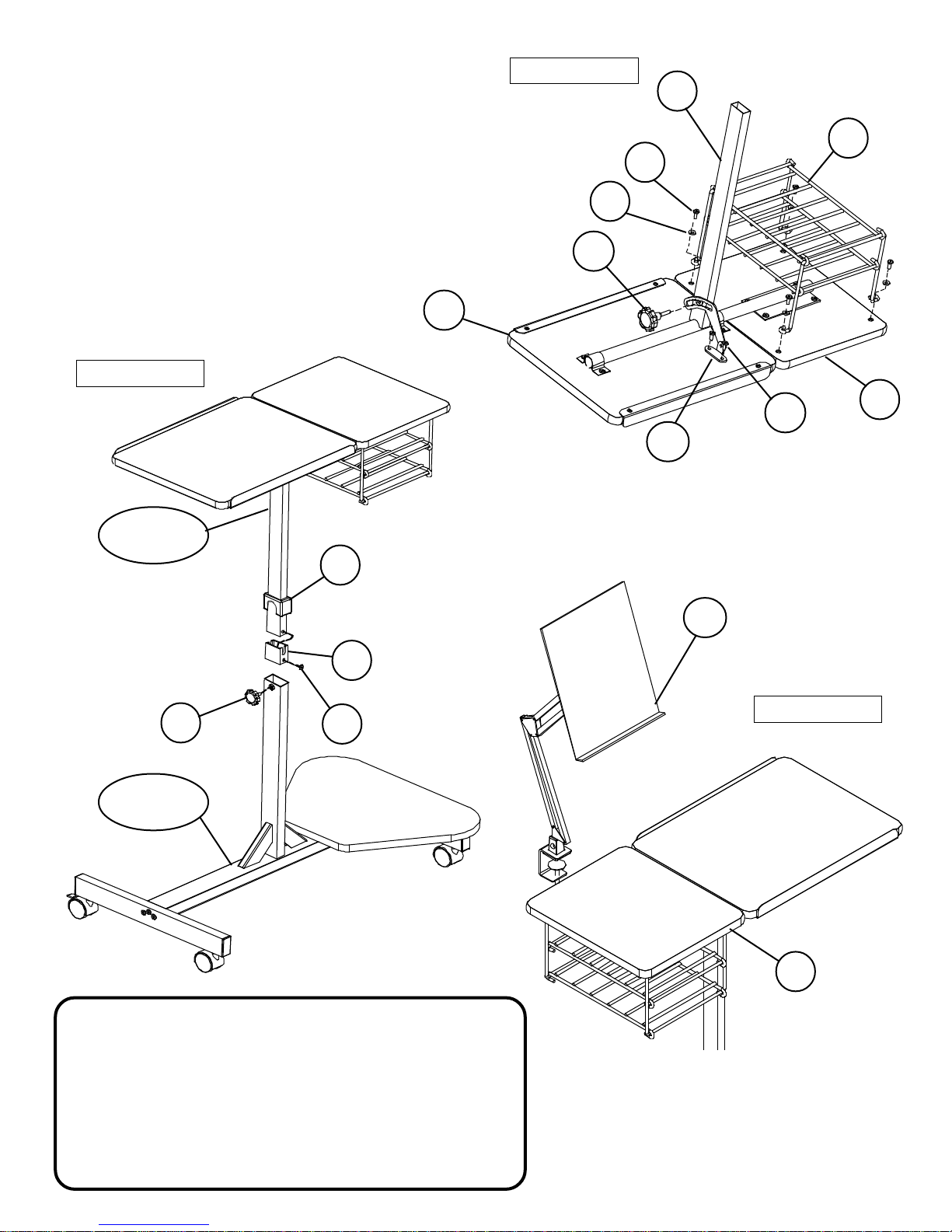
9. Attach Storage Rack (P-8) to the Accessory
Shelf (P-5) using 4 Flat Head screws (A1) and
4 Flat Washers (E) as shown in illustration # 4.
Illustration # 4
P-4
10. Attach Tilting Bracket (P-10) to the T op
Platform (P-6) using 2 Flat Head screws (A).
Secure Tilting Bracket to Upper Insert (P-4)
using the Large Knob (G1).
1 1. Please refer to the details on next page for
assembling Plastic Cap (M), and
the Plastic Sleeve (N).
Illustration # 5
Upper Insert
Assembly
M
P-6
P-8
A1
E
G1
P-5
A
P-10
12. Insert Upper Insert Assembly into
Lower Receiver Assembly , adjust to desired
height and secure with the Small Knob (G2)
as shown in illustration # 5.
N
G2
Lower Receiver
Assembly
A
Should you require assistance during assembly,
please call our Customer Service Department
Monday - Friday 8 a.m. - 5 p.m.
Central Standard Time
Toll-Free Customer Service
1-800-749-2258
P-12
Illustration # 6
P-5
13. Attach Copyholder (P-12) to
Accessory Shelf (P-5) at desired
location and secure with bottom clamp
as shown in illustration # 6.
Lap2c_newasm - 03/11/02
Page 5
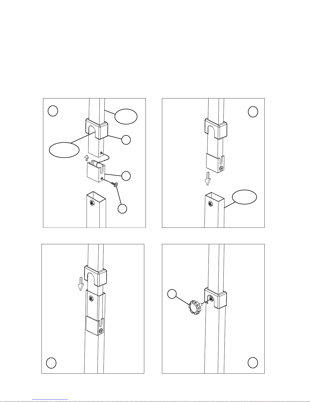
DET AILS OF ASSEMBLING PLASTIC CAP ‘M’ & SLEEVE ‘N’
1. Slide Plastic Cap (M) [with Cutout on the same side as the tilting bracket on the Upper insert],
then attach the Plastic sleeve (N) over the end of insert. Make sure that the hole on the Part N
and the hole on the Upper insert tube line up, then attach it with a Flat Head screw (A).
2. Insert Upper insert into the Lower Receiver tube, and slide Part M down, so that it should be
resting on top of the Lower Receiver Tube. Adjust to the desired height and secure with the
Small Knob (G2) as shown in Illustration below .
1
Cut out on
Part M
Upper
Insert
M
N
A
2
Lower
Receiver
3
3
G2
4
 Loading...