


27614
Beta Cart
Assembly Instructions
1
27614 Beta Cart
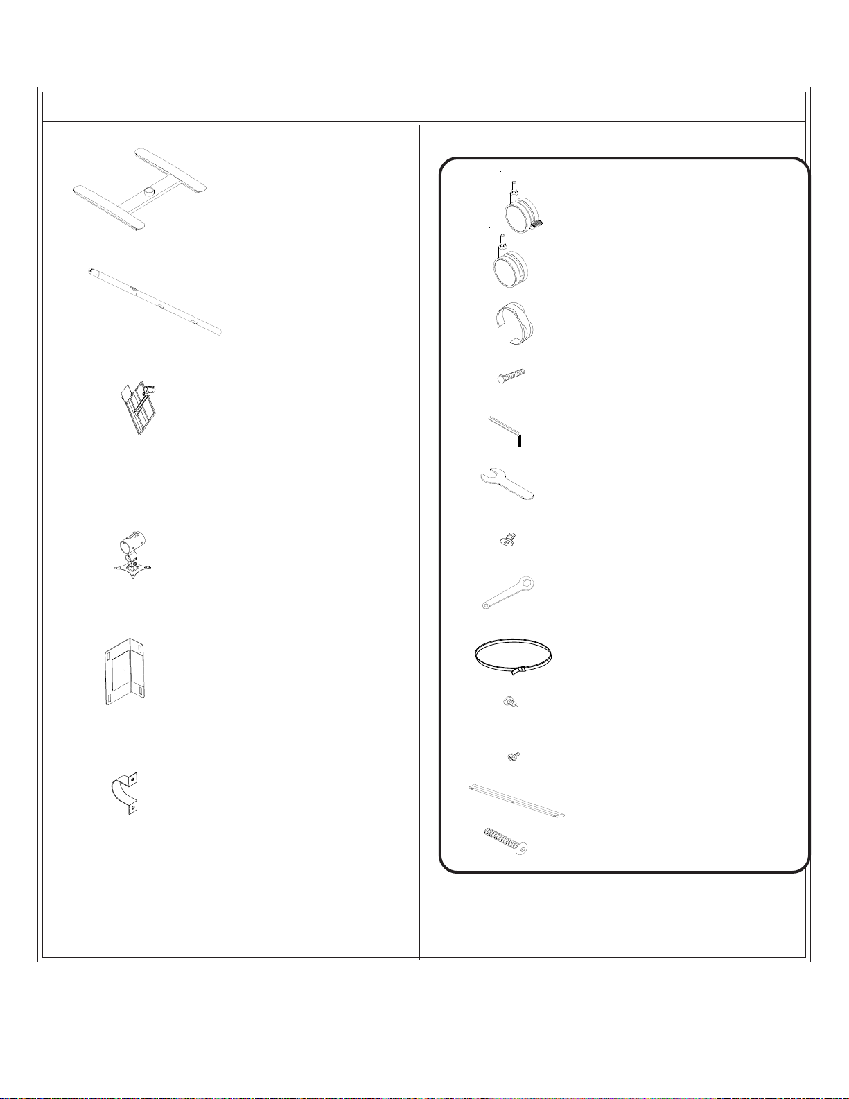
Part Drawing Description Qty
P-1 Base 1 EA
P-2 Pole 1 EA
P-3 Main Platform 1 EA
Part Drawing Description Qty
Hardware List
A 3” Locking Caster 2 EA
B 3” Non-locking Caster 2 EA
C Electrical Clip 3 EA
D
E Allen Wrench 1 EA
F Caster Wrench 1 EA
Long Bolt 1 EA
P-4
P-5
P-6
Monitor Mount 1 EA
CPU Mount 2 EA
CPU Mount Clamp 2 EA
G
H
I
J Screw M6*12mm 4 EA
K Book Stop Phillips Screw 3 EA
L Book Stop 1 EA
M Electrial Strip Screws 2 EA
(Optional)
Wrench 2 EA
Screw M6*15mm 4 EA
CPU Strap 2 EA
2
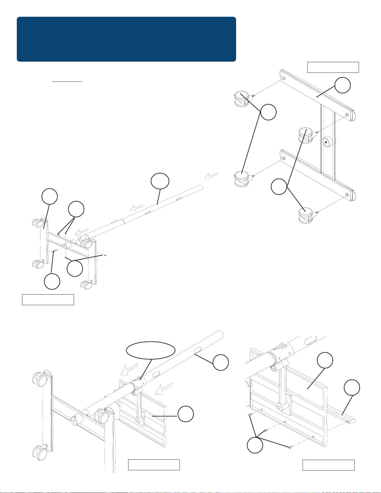
Assembly Diagram
R
EAD THROUGH INSTRUCTIONS FROM BEGINNING
TO END
1.)
2.)
Screw in two Locking Casters (A) into the bottom front of
BEFORE
STARTING TO ASSEMBLE UNIT
.
Identify and Separate all the Parts and Hardware.
the Base (P1) and two Non-Locking Casters (B) as shown
in Illustration # 1. Tighten casters with Caster W rench (F).
3.)
Insert the Pole (P2) into the Base (P1) and secure to the Base
using one long Bolt (D) and four small Screws (G) as
shown in illustration #2.
P2
P1
G
Illustration # 1
P1
A
B
D
Illustration # 2
G
4.)
Clamp Lever
Open the clamp up on the Main Platform (P3) and slide
the assembly down the Pole (P2). Make sure the
friction button inside the clamp is retracted. When the
Main Platform is in position, lock the clamp lever down
to secure it in place as shown in illustration #3.
Attach the Book S top (L) to the Main Platform (P3) using
three Book Stop Screws (K) as shown in illustration #3a.
P2
P3
K
P3
L
Illustration # 3
Illustration # 3a
3
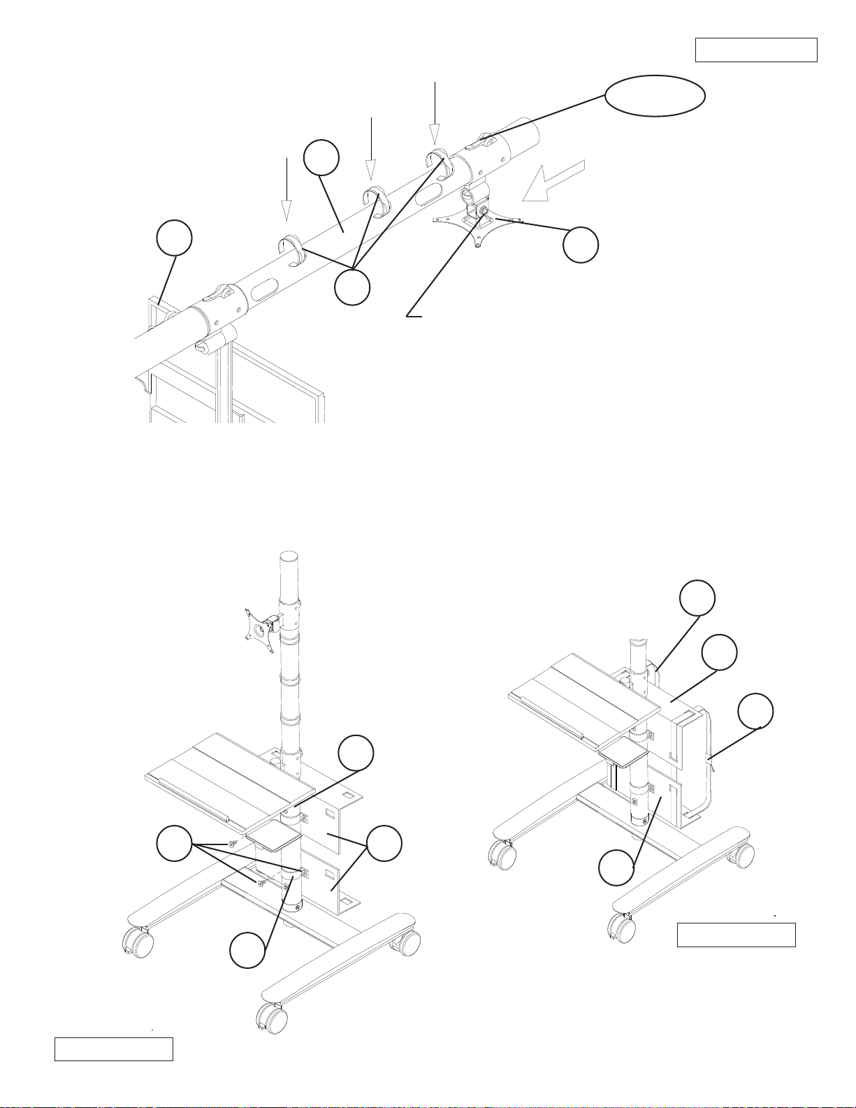
5.)
Slide the Monitor Mount (P4) down the
Pole (P2) above the Main Platform (P3)and
tighten the clamp lever down to lock in place.
See illustration #4.
P2
Illustration # 4
Clamp Lever
P3
C
P4
5A.) T o adjust the tension of the Monitor Mount (P4),
remove caps and use the Wrenches (H) to
tighten or loosen nuts.
Snap-On three Cable T ies (C) onto the Pole (P2) .
6.)
See illustration #4.
7.)
Attach the two CPU Mounts (P5) to the Pole (P2) using four Screws (J) through two CPU Mount
Clamps (P6) as shown in illustration #5. T ighten Screws (J) with Allen W rench (E).
I
Illustration # 5
P5
I
P2
J
P6
P5
P5
Illustration # 5a
7a.) Use two CPU Strap s (I) through
the slots in the CPU Mounts (P5) to
secure your CPU in place. See
illustration #5a.
27614_07-08-14
4
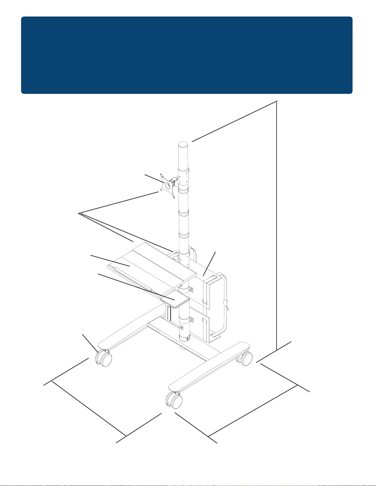
All Parts Have
Adjustable
Height
27614
Beta Cart
VESA 3 and
VESA 4 Mount
66 1/2”
20” W X 12” D
Keyboard Shelf w/
6 5/8” X 6” Mouse
3” Casters
25”
Adjustable CPU
Holder
23”
27614_1-24-14
5
 Loading...