


Safety is our
greatest concern.
We work at it.
BALL VALVES
Raising the Threshold of Quality
Lowering the Cost of Ownership
Contents
1
®
Balon Mission 2
Manufacturing 3
The Company 4
The Valve 5
Sealing Principle 6
Valve Construction and Design 7
Stem Design 8
Fire Safety 10
Balon Installations 11
Series F, Screwed End 12
Series F, Flanged End, Lever Operated 18
Balon Installations 23
Series F, Flanged End, Gear Operated 24
Series F, Ductile Iron, Flanged End, Lever Operated 26
Series US, Weld X Weld 28
Series US, Weld X Flange 30
Series S, Screwed End 32
Series LM, Screwed End 36
Series LS, Screwed End 38
Balon Installations 40
Technical and Engineering Data 41
Product Identification Key 46
Terms and Conditions 47
Balon Installations 48
Click on title to jump to that page.

The Balon Mission
2
®
■ Produce valves with the safety of those who use
them as our uppermost and defining goal.
■ Provide our customers with valves
which perform as promised, at a price
which reflects their true value to the user.
■ Meet the service needs of our customers by
maintaining a trained full-time staff of field
technicians located in all geographical areas.
■ Respond promptly and courteously to all customer
and distributor inquiries, questions, and problems.
■ Make certain that all Balon employees
understand and implement our commitment
to customer attention and customer satisfaction.
■ Treat our vendors, customers, distributors, and
employees with equanimity and honesty.
To assure growth for
the Company and
opportunity for all
employees, it shall be
our dedicated aim to:
Manufacturing
®
3
Balon: The Company
®
4
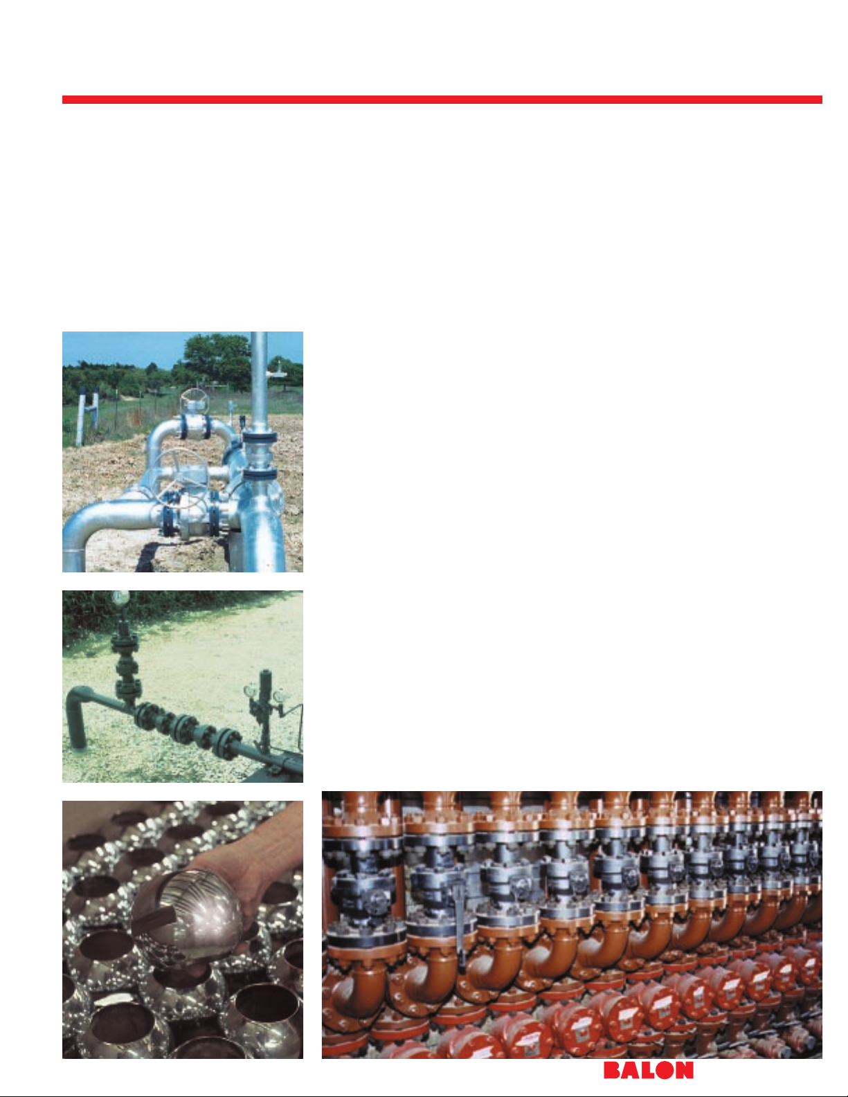
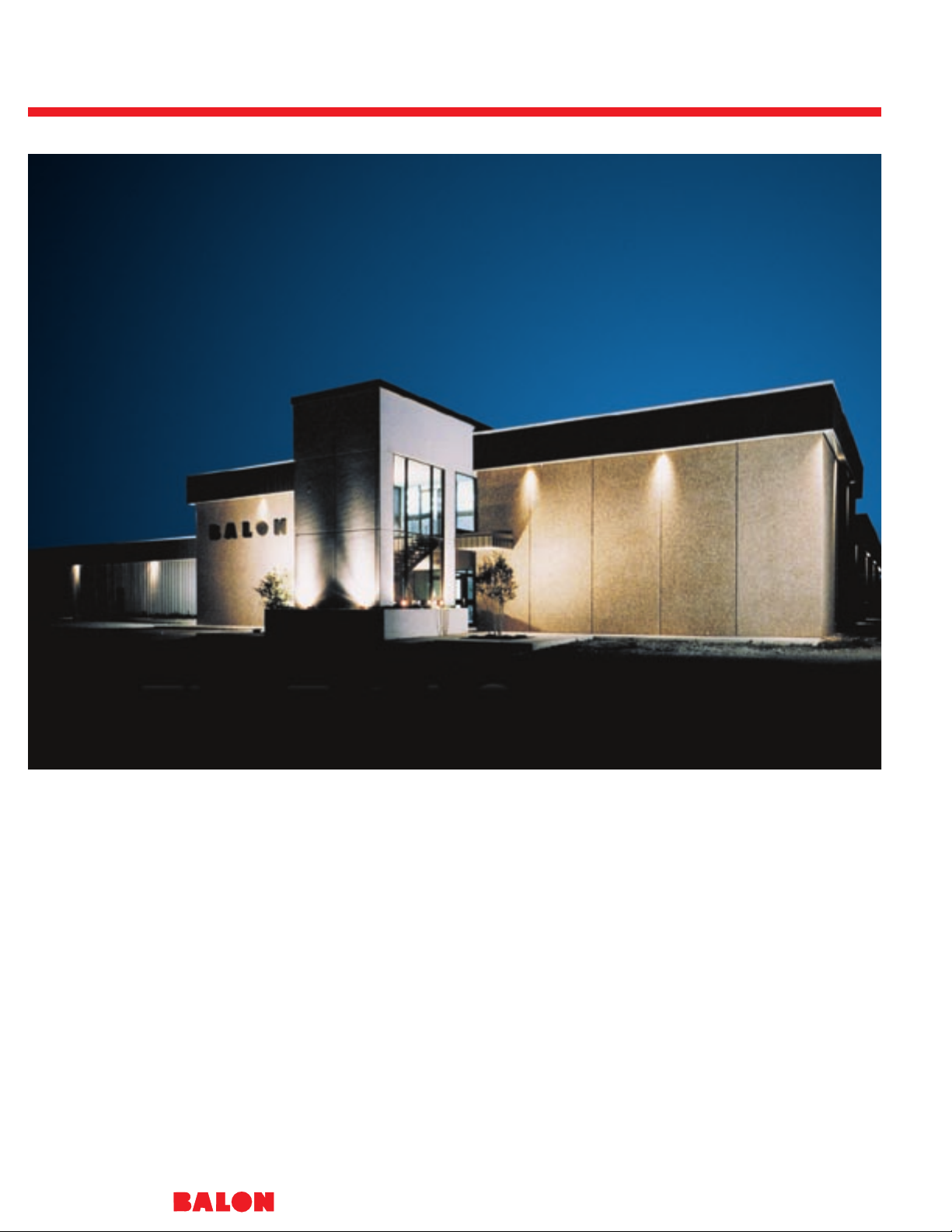
Situated on ten acres in Oklahoma City,
this facility typifies the Balon concept
and approach to producing a superior
valve.
Because growth has been rapid, it has
been a policy to gear ahead of the
actual demand so that good deliveries
can be sustained and so that surges in
demand do not restrict our capability to
pursue an ongoing program of product
improvement and expansion.
Moreover, it has been our policy over
the years to control the manufacture of
our valves in every possible way, and
this has meant basic manufacture of all
components, including molding of
seats, and close-tolerance machining of
balls.
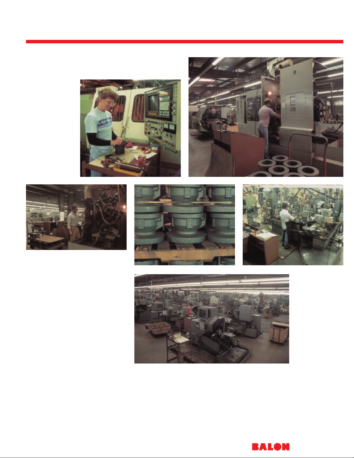
The people who manufacture the Balon
ball valve take pride in their work. And
it is this pride of craftsmanship that sets
Balon apart from its competition.
By utilizing the most modern
equipment and facility available today,
Balon is able to do many things more
quickly than those manufacturers
whose equipment and facilities have
become outdated and costly. We will
continue to recognize that the Balon
name must be synonymous with raising
the threshold of quality and lowering the
cost of ownership.
©
2001 Balon Corporation
Balon: The Ball V alve
®
5
Unblemished Safety Record:
After almost four decades of producing
valves and having no injuries nor property damage result from the failure of a
Balon valve, we are proud to claim that
we make the safest ball valves available
on the market today.
This safety record did not come from
shying away from the tough high
pressure applications in the field. It did
not arise from cutting corners to lower
the cost of making valves to the
ultimate peril of those who operate
them. It was not borne of cosmetic
contrivance nor gimmickry and
gadgetry.
It has been the calculated result of a
rational, intentional and concerted effort
to address every possible hazard and
to design and manufacture valves with
an inherent margin of safety far
surpassing that of others on the market.
Total Commitment: More than
innovative design goes into producing a
superior valve. More than controlled
and precision manufacturing methods.
More than overall engineering expertise.
More than effective marketing and
distribution. To produce a valve noted
for its superiority in performance, safety,
dependability and for its consistent
quality implies a total commitment in all
of these phases.
Combined Effort: Balon Corporation,
since its beginning in 1965, has
coupled improved design features,
advanced manufacturing methods and
practical common sense engineering
approaches with a well planned, highly
supportive and field channeled
marketing and distribution program.
The natural result of this effort has been
that the Balon ball valve has attained a
reputation for excellence unequaled by
any other ball valve on the market.
Individual Pride: Many manufacturers
have adopted the philosophy that
valves are best made by turning them
out on sophisticated machines
incapable of exercising judgment as to
the quality of the final product. At
Balon, we believe that people — not
machines — produce valves. Our valves
are produced by perfection-minded
craftsmen who use specialized
machines as tools to help them make a
better valve.
Continued Support: It is with this
philosophy in mind that we will continue
to provide a better valve, an advanced
valve. And we will support this product
with a concerted program of design,
manufacturing, engineering and
marketing.
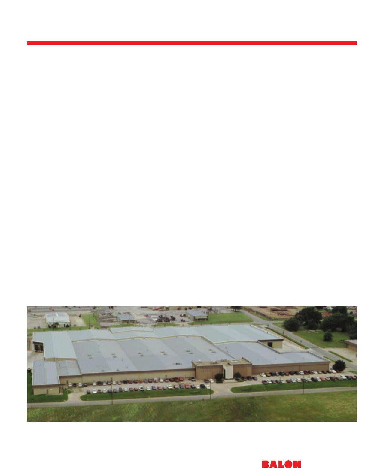
Balon Corporation’s 260,000 square feet of modern office and manufacturing capability is shown in this aerial view.
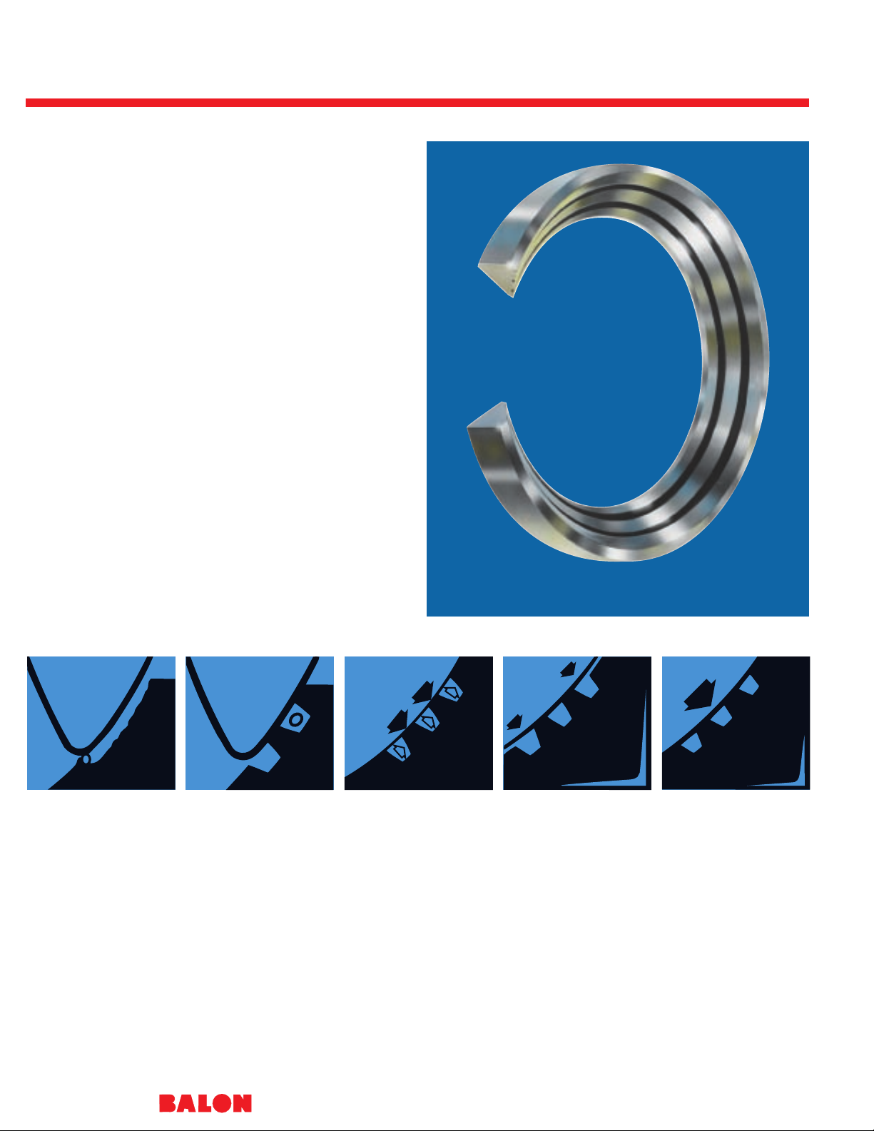
Multi-Seal: The Heart of the V alve
®
6
Notice the grooves. These grooves loosely receive any grit
that might be present when the valve is closed. When the
valve is opened, the foreign matter washes harmlessly away,
where an ordinary valve seal could have been scored across
its entire surface. Balon’s seal is good as new.
Notice the seal rings. Not just one ring… a series. That’s
where Multi-Seal gets another big sealing edge over plain
seals. The rings assure a concentrated seal, providing a bubble tight seal at high and low pressures, the tighter the seal…
the better the shut-off.
Notice the tapered outer walls. These tapered walls on the
Multi-Seal provide automatic seal-to-ball tensioning and selfadjustment to wear. Much longer life and complete troublefree performance is what you get. That’s why you don’t need
a repair kit.
How long will the Balon Multi-Seal last? Our sales records
of replacement seats indicate that most Balon valves sold
have provided many years of trouble-free performance.
It has been tested on water pumped at 1,000 psi operating
pressure with shock loading on shutoff up to 1,800 psi. After
a million shutoffs, it still sealed bubble tight.
Patented
ORDINARY SEALS
are damaged during
shutoff. As flow is
squeezed through fineline opening, foreign
particles are trapped.
Complete shutoff
grinds them into seal.
Results: premature
damage, leakage,
valve failure.
MULTI-SEAL
receives particles
loosely in grooves, to
be washed harmlessly
away during next
opening. Valve seals
bubble tight again,
through repeated
shutoffs.
MULTI-SEAL’S
series groove design
features blunt-edge
seal members for
superior sealing
efficiency. And the
grooves form supertight “fluid seal rings.”
Each seal member,
working with the next
one, creates exclusive
“staged differential
pressure sealing,” for
tightest shutoff
possible at all
pressures.
MULTI-SEAL
adjusts itself to wear!
Outer walls are tapered
to permit selfcompensation to valve
load and seal
engagement demand.
The design permits
thrust loading to
realign seat toward
optimum sealing
engagement.
THE MULTI-SEAL
DESIGN permits
selection of seal
material best suited to
abrasive, high and low
pressure applications
in toughest services.
And the relief pockets
formed by the tapered
walls, with the series
grooving, provide selfcompensation for swell
to permit easy-turning,
long-life operation. it
takes a better seal to
make a better valve…
and the best ball valve
is a Balon.
The Balon V alve: T otally Advanced
®
7
Unique Sealing Approach
The Balon ball valve is the culmination
of many years of arduous design and
development effort which has been
focused on providing a clearly better
choice in ball valves. It is a refinement
of features proven superior during
usage of Balon ball valves in thousands
of installations since 1965.
As described on the facing page,
the multi-seal seat design has given
impetus to the development of an
overall valve which embodies several
design improvements.
Backseated Stem
Stems are backseated and therefore
blowout proof. And they provide metalto-metal backup sealing in the event of
a fire. This secondary metal-to-metal
sealing is also provided internally behind
the seat area.
Simplified Top Works
Bolts and glands and complicated stem
assemblies are totally absent in the
Balon valve to assure a simpler, more
trouble-free valve. Hazards associated
with bolted stem retainers and packing
adjustment screws or bolts have been
eliminated. Even the stops are internal
and give dual precise topping support
during opening or closing. The stem
area is grease-packed and protected
by dual plastic weather guards to shield
this vital area from external elements.
Precise Manufacturing Control
Balon uses only the highest quality
materials to assure the strength and
uniformity necessary for applications
where they are used. To further
enhance the overall operational
superiority of the valve, all balls are
machined in-house by Balon’s spherical
machining process which assures a
consistently accurate spherical contour.
They are superbly finished and polished.
This high integrity finish, along with
multi-seal’s advanced sealing capability,
provides highest sealing efficiency and
substantially reduced operating torque.
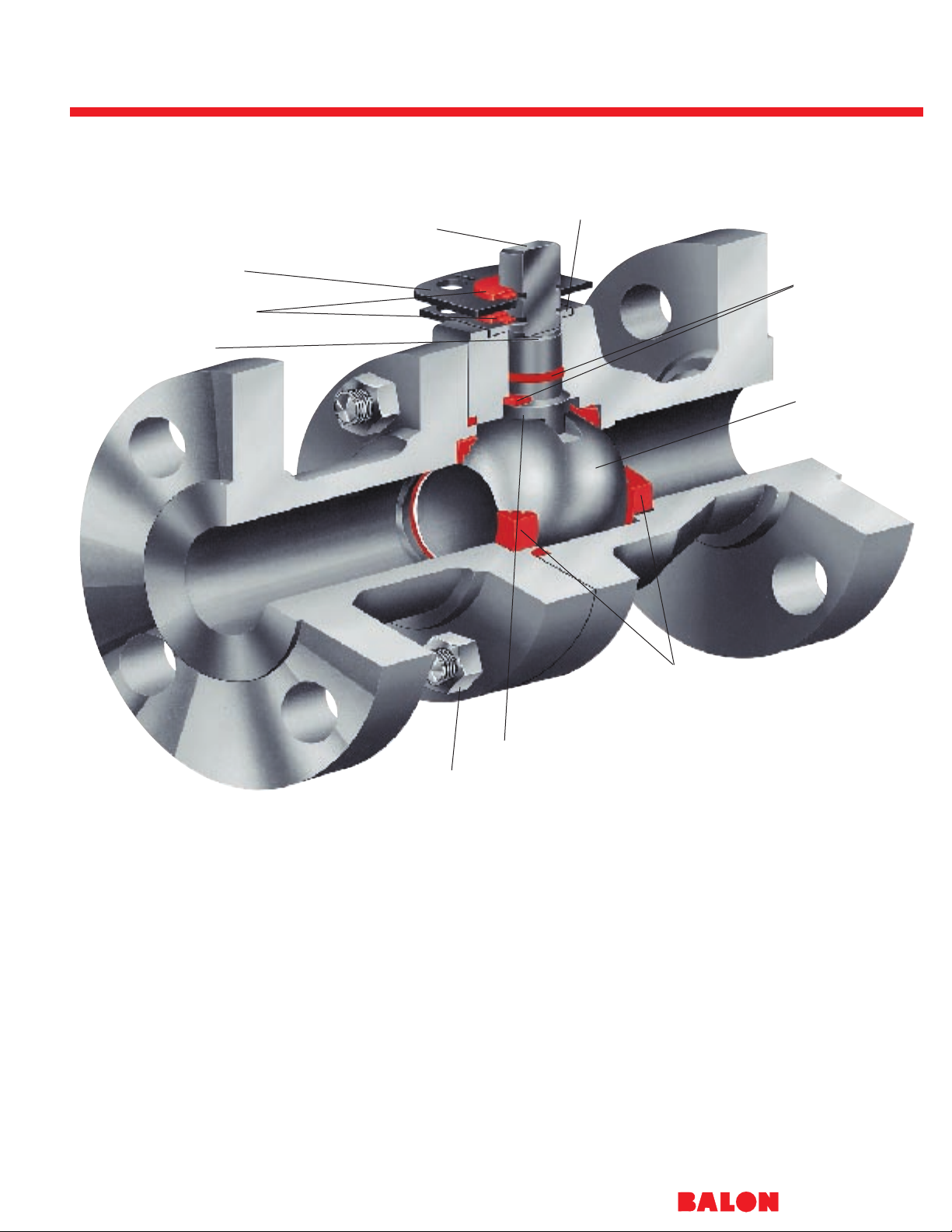
Valve safety is no accident. We do it by design.
SAFETY SHEAR GROOVE
PROTECTIVE WEATHER GUARDS
LOCKING PLATE
RECTANGULAR STEM WRENCH AREA
PATENTED
INTERNAL TWIN STOPS
SELECTIVE DUAL
STEM SEALING
ULTRA SMOOTH
HIGH SPHERICITY
BALL
PATENTED
MULTI-SEAL SUPER
EFFICIENCY SEALING
BACKSEATED BLOWOUT-PROOF STEM
STRONG BOLTED CONSTRUCTION
Balon has eliminated the need for grease fittings, lube channels, and regular lubrication, versus other designs.
•
•
•
•
•
•
•
•
•
•
•
•
•
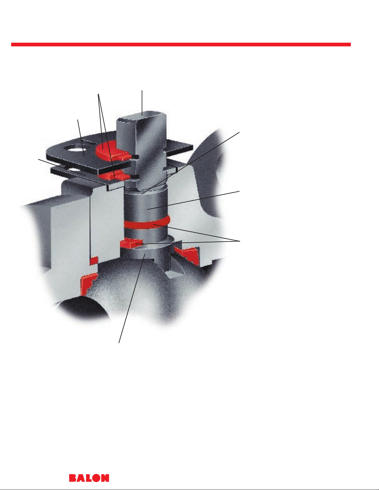
A T otally New Concept in Stem Design
®
8
Simple Design
In keeping with Balon’s philosophy of
design which envisions simplification
and improvement instead of improvement by complication, the Balon stem
design solves many problems associated with the common stem design. The
overall utility of the ball valve is related in
no small way to the basic stem design.
Certain standard designs originated
early and were followed through by ball
valve manufacturers in the years following the advent of the ball valve itself
during World War II.
The Balon Stem: New
Solutions For Old Problems
The Balon design represents the result
of a total attack on specific problems
associated with the outdated design. In
the past, it has been a frequent practice
to retain stems by use of external
retainers secured by use of external
bolts or screws. Often these bolted
arrangements also provided stem packing adjustment. The problem of leaking
stems was amplified because of the
complexity of the assembly itself.
The absence of backseating in early
designs opened the way for stem
blowout in the event of failure of the
retaining assembly or as a result of
forcible operation of the valve.
In many former designs, double O-rings
were incorporated on the theory that
should one O-ring fail to seal, then the
second O-ring would perform the sealing job. However, higher pressures
trapped between the O-rings often
caused high operating torque and other
operating problems.
A Combination of Improvements
As shown here, the Balon design is
simple, yet solves these problems. The
clean, functional design of the stem
assembly represents dramatic improvement in many ways over conventional
designs. As is true of the overall Balon
approach, the Balon stem does not
present just one special modification or
design innovation. Rather, it represents
the bringing together of interrelated
improvements, resulting in total
improvement and total superiority.
PROTECTIVE WEATHER GUARD
KEEPS MOISTURE FROM STEM AREA
LOCKING PLATE STANDARD
BODY KEYED
STOP PLATE
CONTAINS
PATENTED
INTERNAL
TWIN STOPS
RECTANGULAR WRENCH STEM AREA
FACILITATES USE OF STANDARD WRENCH
SAFETY SHEAR GROOVE - PREVENTS
STEM BLOWOUT RESULTING FROM
EXCESSIVE TORQUE
EXTRA LARGE STEM FOR
STRENGTH AND SAFETY
SELECTIVE DUAL SEALING WITH THRUST
WASHER FOR HIGHER PRESSURE AND O-RING
FOR LOWER PRESSURE
METAL-TO-METAL BACKSEATING FOR FIRE
SAFETY AND BLOWOUT PREVENTION
•
•
•
•
•
•
•
•
•
•
Balon has eliminated the need for grease fittings, lube channels, and regular lubrication, versus other designs.
Safer ...Simpler ...Better Sealing
®
9
NO SPECIAL HANDLE NEEDED
While handles can be provided for
operation of the Series F and Series S,
the heavy-duty rectangular stem design
allows for usage of standard wrenches
where it is necessary to conserve
space, and to prevent accidental operation of the valve, or simply where standard wrenches are more convenient.
To further enhance the service life and
ease of operation, the stem area is fully
grease-packed and then sheltered by
dual nylon weather guards. External
elements such as dirt, sand, and salt air
atmosphere are kept out.
NO BOLTS, SCREWS, PACKING
GLANDS
The Balon design eliminates
troublesome bolting, adjustment
screws, and packing glands. Problems
of adjustment, blowout resulting from
failure of retaining assembly, and
external attack by corrosion and foreign
abrasives are all solved. By simplifying
the stem assembly, fewer parts are
involved and therefore the possibilities
for trouble are significantly reduced.
Because there are no grease channels
or lubricating ports there are no leak
paths which can result in stem leakage.
PATENTED INTERNAL DUAL STOPS
Instead of external stops and exposed
bolting, the stem is supported laterally
by a stop plate keyed into the body
head. This plate has integral broached
stops contralaterally positioned so that
the stem is stopped simultaneously on
both sides whether being opened or
closed. This dual stopping action eliminates deflection and stress on the
stem. Perfect alignment is assured in
SELECTIVE DOUBLE SEALING
Balon utilizes a TFE thrust washer for
primary sealing at higher pressures.
For lower pressures and vacuum, the
O-ring provides the sealing. The stem
region between the two seals cannot
remain pressurized - as can happen in
conventional double O-ring arrangements - since at lower line pressures,
the TFE seal will permit bleed back into
body region. Two seals, but only one
acting at any given time.
Safety is our greatest concern. We work at it.
the stem bore, and therefore more trouble free and longer life stem and stem
seal service. Dual stops keep ball in
precise position against the seat, and in
the open position this prevents exposure of the seat to damage and wear
from the flow. Sealing effectiveness is
sustained and extended.
BLOWOUT PROOF
Notice that the stem is backseated
against an inner shoulder, and not
retained by external bolts or screws or
retaining plates. Blowout is inherently
denied by this positive method of stem
retention. Balon has machined a safety
shear groove on each side of the stem
at the base of the wrench flats, but
safety above the stem seals, and above
the inner shoulder. Should excessive
torque be applied to the stem, it would
shear above the shoulder and above
the sealing area. No blowout. No
release of hazardous material.
A More Complete Solution to Fire Safety
®
10
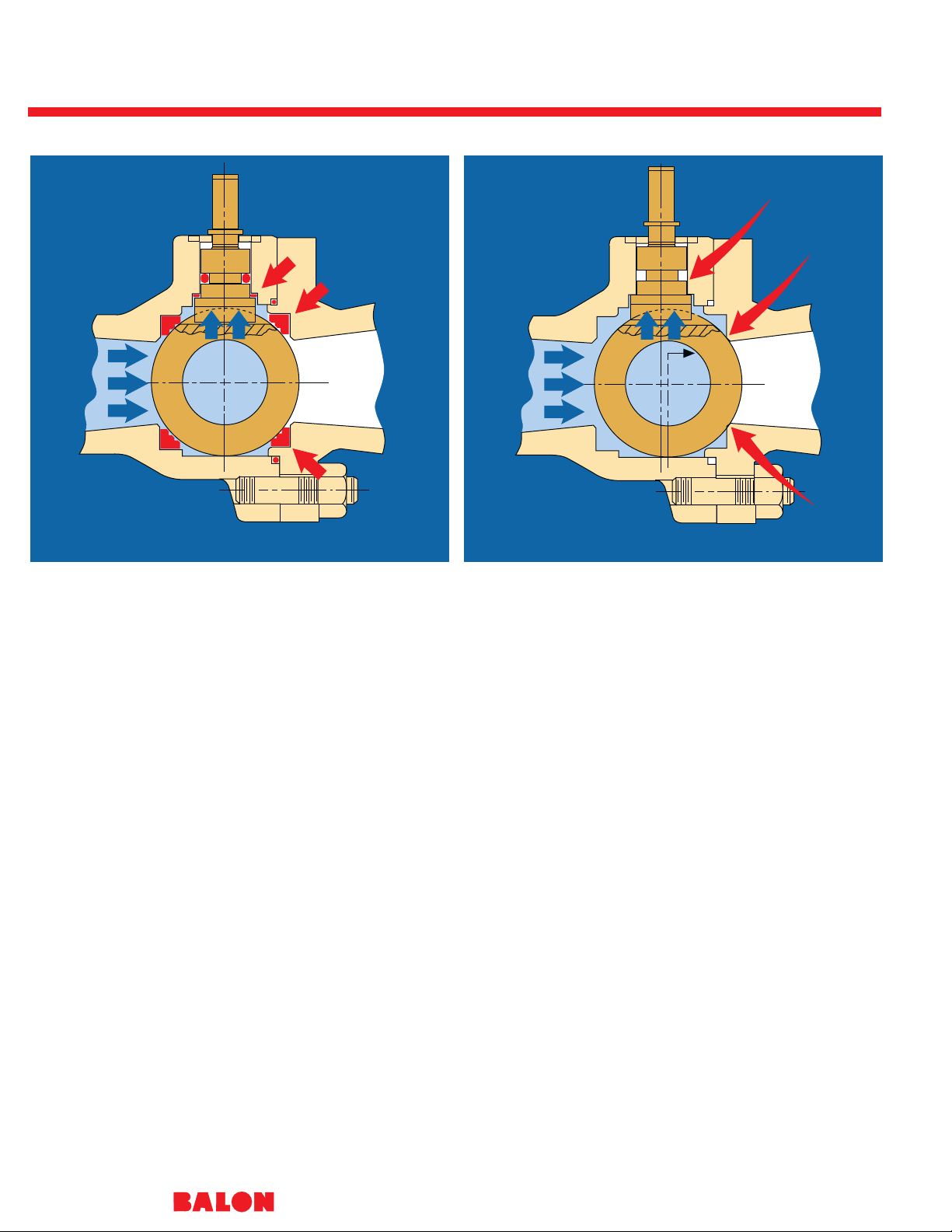
Figure A: Valve closed and seals intact. Figure B: Valve is closed, seals completely dissipated.
In 1965, after many years of
development and testing, Balon
patented and introduced a ball valve
which represented a dramatic turning
point in valve safety. It was the first ball
valve with a backseated stem to prevent
stem blowout; first with packless stem
gland housing, eliminating stem
adjustment mechanisms; first with a
stem shear groove to assure controlled
stem breakage above the backseat in
the event of twist-off; first with full
spectrum fire safety for metal-to-metal
secondary sealing at all potential leak
points. Balon then encased these
safety improvements in a rugged bolted
body assembly capable of better
withstanding violent thrust loading and
line stresses so common in highpressure line applications.
Fire safety in ball valves has become a
major consideration as more and more
ball valves have been used in hazardous
environments.
The Balon ball valve has been designed
to provide maximum backup sealing in
the event resilient seals are destroyed
by heat or fire.
Controlled Spacing
The valve internals, with seals intact,
can be seen in Figure “A.” In the closed
position the ball is held off of secondary
metal seat provision.
The seat and seat pocket are made
oversize in radial dimension, allowing
close spacing of the ball and metal seat
provision. In operation, with prime seals
in place, this controlled spacing prevents
damage to the surface finish of the ball.
It can also be seen that the stem is
backseated, and with seals in place the
primary stem seal holds the stem off
of metal shoulder machined in the
valve body.
Secondary Stem Seal
In Figure “B,” the seals have been fully
dissipated, ball has moved downstream
onto the secondary metal seat, and the
stem has been checked, metal-tometal, against the inner shoulder.
As can be seen, the stem is free to
move upward when subjected to a
slight amount of pressure, onto the
machined metal inner shoulder, thus
substantially restricting any flow past
the stem into the atmosphere.
Straight Ahead Ball Movement
The stem tongue is keyed into a linear
milled slot, straight and perpendicular
to the bore of the valve. In the closed
position, the ball is free to move downstream onto the secondary metal seating, functioning at that moment as a
simple ball check valve.
The ball itself is confined in the body
with just enough vertical and horizontal
clearance to assure free and easy
operation. This keeps the ball in uniform
alignment so that ball movement onto
backseating - should it become
necessary - is consistently on a straight
course, without deflection up, down,
or sideways.
The valve may be positioned in either
vertical or horizontal installations, and
retain its secondary metal-to-metal
sealing capability.
These very simple provisions are
intended to provide full operational
safety, but of course positive assurance
of total fire safety cannot be given due
to the many variable conditions which
can arise. Every attempt has been
made in the design of the Balon valve to
provide as safe a valve as is practicable
within the scope of economic feasibility
for the user.
Balon ball valves have been
successfully tested by an independent
laboratory in accordance with API
Standard 6FA “Fire Test For Soft
Seated Ball Valves.” Results of this
testing are available on request from
Balon’s headquarters office.

Balon Installations
®
11
Designed...
to give superior performance where
superior performance is critical — in the
field. Simple, yet effective. Safe, yet
practical. Versatile, yet economical.
Built...
for the rugged and demanding oil and
gas applications. Stronger. Tougher.
Crafted for hard use and extra
staying power.
Proven...
with millions of valves in the field —
exceptionally dependable, more troublefree, and capable of indefinite maintenance-free service life.
Series F Screwed End
®
12
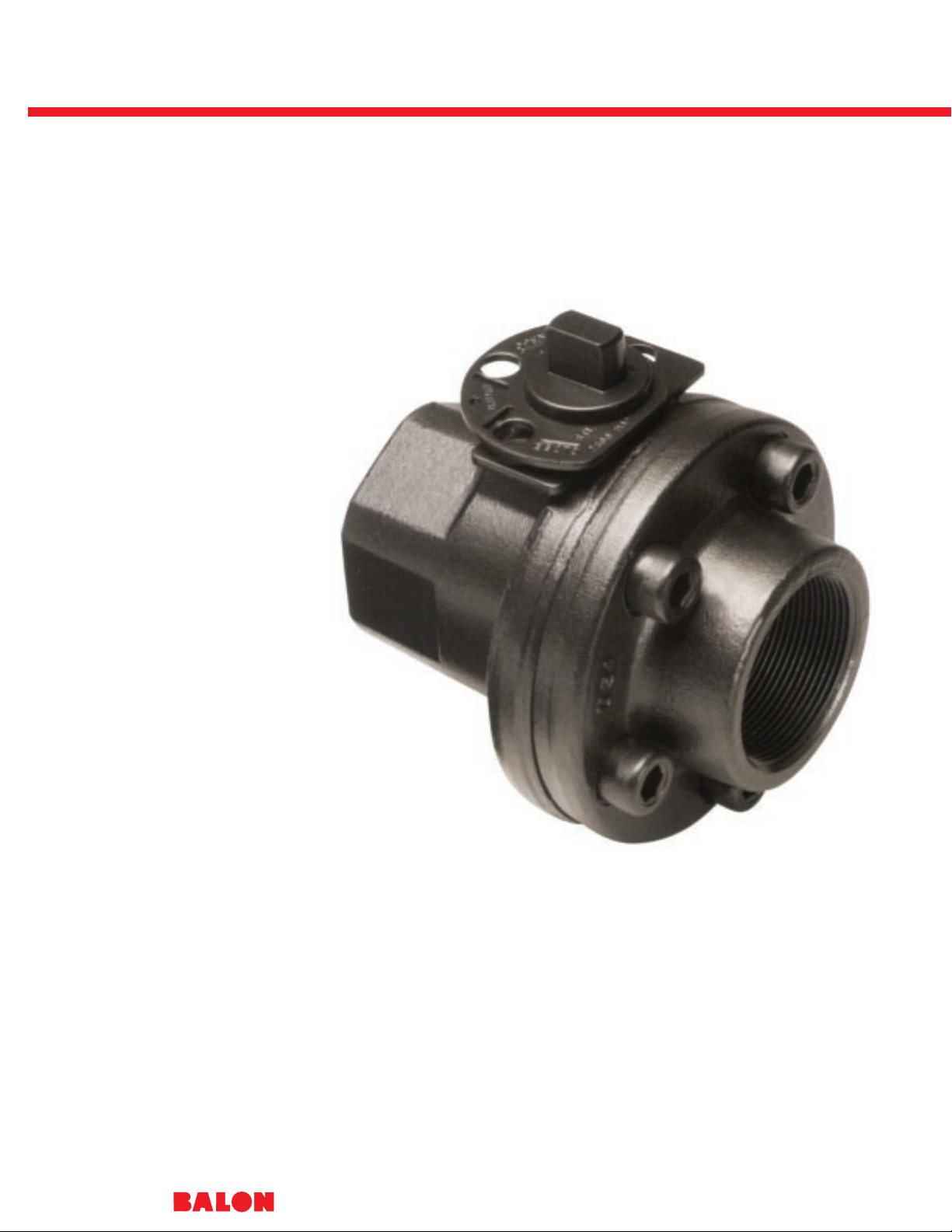
The Balon Series F carbon
steel screwed end ball valve is
of bolted two-piece construction
to assure positive protection
against end adapter blow-out
which can occur in most
screwed construction valves.
The Series F is available to
meet a wide range of pressure
and applications, and when
ordered with 316 stainless
steel ball and stem it meets
NACE requirements.
Firesafe design and built-in
locking device are standard on
the Series F.
Carbon Steel
®
13
BALON SERIES “F” - CARBON STEEL - SCREWED END - DIM. DATA
CAT. NO.
STANDARD TRIM NACE TRIM
SIZE
CARBON STEEL 316 STAINLESS
PORT WP A B C D E F G H J L M N
BALL & STEM STEEL BALL & STEM
1 x 1 x 1 1F-F93-SE 1F-F93N-SE 1 2500 37⁄8115⁄16115⁄1633⁄823⁄
8
1
⁄2.340 .685 11⁄817⁄843⁄82
1 x 1 x 1 1F-F03-SE 1F-F03N-SE 1 3000 37⁄8115⁄16115⁄1633⁄823⁄
8
1
⁄2.340 .685 11⁄817⁄843⁄82
11⁄2x 11⁄2x 11⁄211⁄2F-F93-SE 11⁄2F-F93N-SE 11⁄22500 51⁄425⁄825⁄851⁄835⁄
8
3
⁄4.434 .873 15⁄821⁄271⁄45
2 x 11⁄
2
x 2 2R-F93-SE 2R-F93N-SE 11⁄22500 5
1⁄
2
23⁄423⁄451⁄835⁄
8
3
⁄4.434 .873 15⁄837
1
⁄45
2 x 11⁄2 x 2 2R-F03-SE 2R-F03N-SE 11/23000 51⁄223⁄423⁄451⁄835⁄
8
3
⁄4.434 .873 15⁄837
1
⁄45
2 x 2 x 2 2F-F93-SE 2F-F93N-SE 2 2000 53⁄427⁄827⁄861⁄843⁄
8
7
⁄8.497 .998 2 31⁄8101⁄453⁄
8
3 x 2 x 3 3R-F93-SE 3R-F93N-SE 2 2000 75⁄8313⁄16313⁄1667⁄843⁄
8
7
⁄8.497 .998 21⁄1641⁄4101⁄453⁄
8
3 x 3 x 3 3F-F63-SE 3F-F63N-SE 3 1500 83⁄843⁄1643⁄1685
3
⁄411⁄16.747 1.373 21⁄241⁄420 63⁄
4
4 x 3 x 4 4R-F63-SE 4R-F63N-SE 3 1500 87⁄847⁄1647⁄1685
3
⁄411⁄16.747 1.375 27⁄1651⁄420 63⁄
4
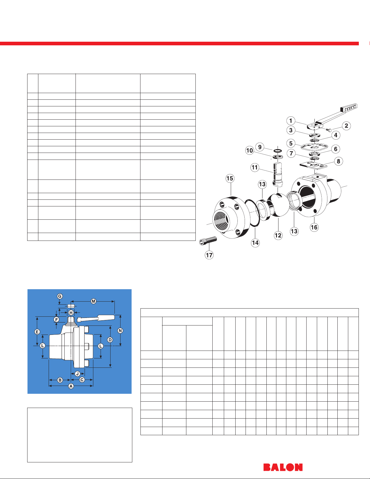
Dimensions
NACE CAPABILITY
Most Series F Carbon Steel and Ductile
Iron Valves can be provided to meet
NACE Standard MR-01-75, current revision, for Sulfide Stress Resistant Metallic
Material for Oil Field Equipment.
WP is for valve equipped with standard nylon seats.
See Chart on Page 43 for TFE ratings.
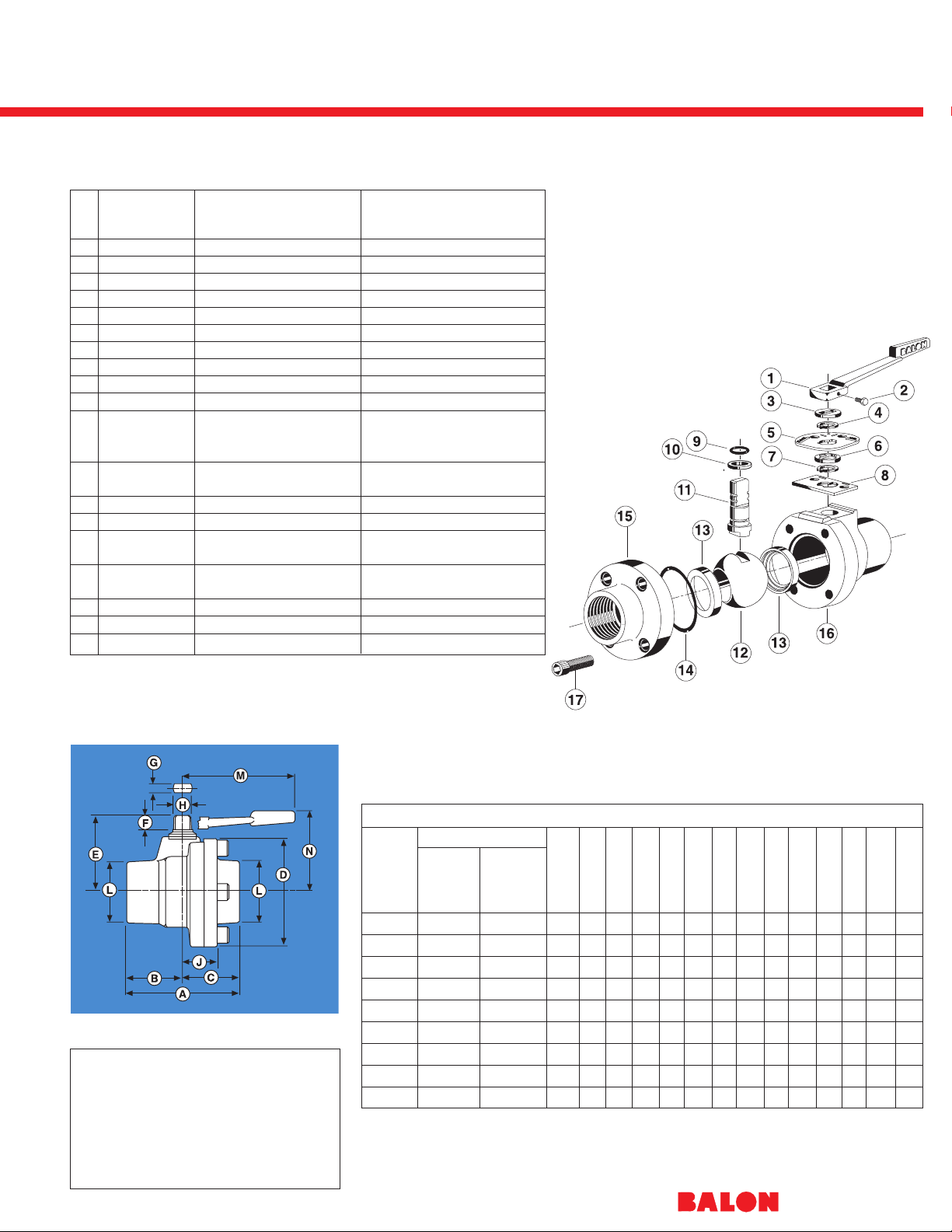
ITEM PART NAME
MATERIAL MATERIAL
(STANDARD) STAINLESS STEEL (NACE)
1 Handle* Ductile iron Ductile iron
2 Handle bolt Standard hex bolt Standard hex bolt
3 Weather guard Polyethylene Polyethylene
4 Lock plate retainer Carbon spring steel Carbon spring steel
5 Lock plate Carbon steel - zinc plated Carbon steel - zinc plated
6 Dust cover Polyethylene Polyethylene
7 Stop plate retainer Carbon spring steel Carbon spring steel
8 Stop plate Carbon steel zinc plated Carbon steel zinc plated
9 Stem O-ring Buna Fluorocarbon
10 Stem seal TFE TFE
11 Stem Carbon steel zinc plated AISI A-316
ASTM A311-79 Class B stainless steel annealed
ASTM A-276-316
12 Ball AISI 1018 nickel chrome plated ASTM A-743-CF8M/316
annealed stainless steel
13 Ball seat Nylon (TFE optional) Nylon (TFE optional)
14 Body O-ring Buna Fluorocarbon
15 End adapter ASTM 216 grade WCB annealed ASTM 216 grade WCB annealed
carbon steel carbon steel
16 Body ASTM 216 grade WCB annealed ASTM 216 WCB annealed
carbon steel carbon steel
17 Body bolts ANSI B18.3 ANSI/ASTM A574 ASTM A-193/B7M
18 Body stud nuts ASTM A-194 ASME SA 194 2H ASTM A-194 2HM
19 Body stud bolts ASTM A-193 ASME SA-193 B-7 ASTM A-193 B-7M
Material Description Lever Operated
Bolted Construction
1" thru 4"
to 3000 PSI WP
* Balon valves are designed to be operated
with a standard open-end wrench.
Handle and Handle Bolt are optional.
Series F Screwed End
®
14
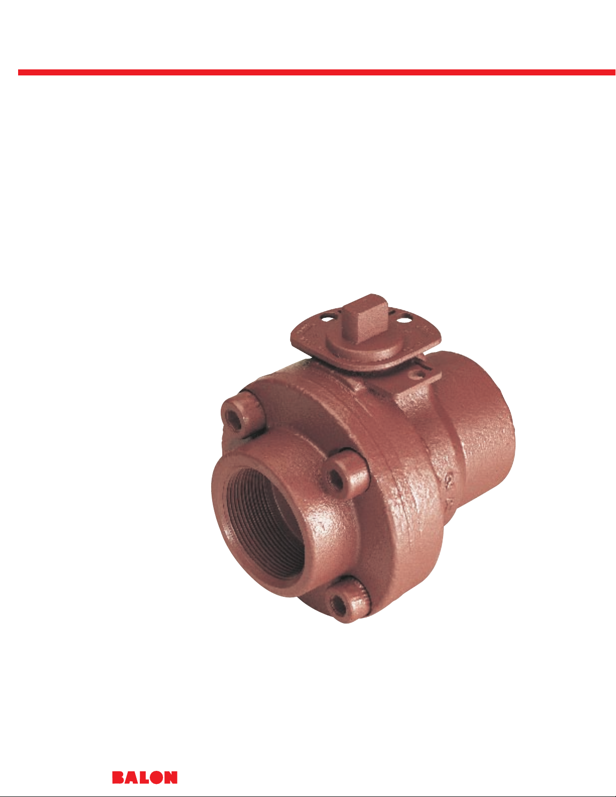
The Balon Series F ductile
iron is an excellent lower cost
alternative to carbon steel
screwed end valves with no
sacrifice in safety or
performance life.
The ductile iron used to make
the Series F is a higher grade
of ductile whose physical
properties are enhanced by
special heat treating that
provides a yield strength
greater than that of carbon
steel, and better overall
corrosion resistance.
Built-in locking devices are
standard, and all Balon ductile
iron valves can be provided
with 316 stainless steel balls
and stems for corrosive media
and to meet NACE
requirements.
Ductile Iron
®
15
ITEM PART NAME
MATERIAL MATERIAL
(STANDARD) STAINLESS STEEL (NACE)
1 Handle* Ductile iron Ductile iron
2 Handle bolt Standard hex bolt Standard hex bolt
3 Weather guard Polyethylene Polyethylene
4 Lock plate retainer Carbon spring steel Carbon spring steel
5 Lock plate Carbon steel - zinc plated Carbon steel - zinc plated
6 Dust cover Polyethylene Polyethylene
7 Stop plate retainer Carbon spring steel Carbon spring steel
8 Stop plate Carbon steel zinc plated Carbon steel zinc plated
9 Stem O-ring Buna Fluorocarbon
10 Stem seal TFE TFE
11 Stem Carbon steel zinc plated AISI A-316
ASTM A311-79 Class B stainless steel annealed
ASTM A-276-316
12 Ball AISI 1018 nickel chrome plated ASTM A-743-CF8M/316
annealed stainless steel
13 Ball seat Nylon (TFE optional) Nylon (TFE optional)
14 Body O-ring Buna Fluorocarbon
15 End adapter ASTM-A395 class ASTM-A395 class
60-40-18 fully annealed 60-40-18 fully annealed
16 Body ASTM-A395 class ASTM-A395 class
60-40-18 fully annealed 60-40-18 fully annealed
17 Body bolts ANSI B18.3 ANSI/ASTM A574 ASTM A-193/B7M
Material Description
BALON SERIES “F” - DUCTILE IRON - SCREWED END - DIM. DATA
CAT. NO.
STANDARD TRIM NACE TRIM
SIZE
CARBON STEEL 316 STAINLESS
PORT WP A B C D E F G H J L M N
BALL & STEM STEEL BALL & STEM
1 x 1 x 1 1F-F92-SE 1F-F92N-SE 1 2000 37⁄8115⁄16115⁄1633⁄823⁄
8
1
⁄2.340 .685 11⁄817⁄843⁄82
2 x 11⁄
2
x 2 2R-F92-SE 2R-F92N-SE 11⁄22000 51⁄223⁄423⁄447⁄835⁄
8
3
⁄4.434 .873 15⁄83 71⁄45
2 x 2 x 2 2F-F62-SE 2F-F62N-SE 2 1500 53⁄427⁄827⁄861⁄843⁄
8
7
⁄8.497 .998 2 31⁄8101⁄453⁄
8
2 x 2 x 2 2F-F92-SE 2F-F92N-SE 2 2000 53⁄427⁄827⁄861⁄843⁄
8
7
⁄8.497 .998 2 31⁄8101⁄453⁄
8
21⁄2x 21⁄2 x 21⁄221⁄2F-F62-SE 21⁄2F-F62N-SE 21/21500 7 31⁄231⁄267⁄851⁄411⁄16.622 1.248 21⁄435⁄816 53⁄
4
3 x 2 x 3 3R-F62-SE 3R-F62N-SE 2 1500 71⁄435⁄835⁄863⁄443⁄
8
7
⁄8.497 .998 21⁄841⁄4101⁄453⁄
8
3 x 2 x 3 3R-F92-SE 3R-F92N-SE 2 2000 71⁄435⁄835⁄863⁄443⁄
8
7
⁄8.497 .998 21⁄841⁄4101⁄453⁄
8
3 x 3 x 3 3F-F42-SE 3F-F42N-SE 3 1000 81⁄841⁄1641⁄1673⁄453⁄411⁄16.747 1.373 21⁄241⁄420 63⁄
4
4 x 3 x 4 4R-F42-SE 4R-F42N-SE 3 1000 85⁄845⁄1645⁄1673⁄453⁄411⁄16.747 1.375 21⁄251⁄420 63⁄
4
4 x 4 x 4 4F-F32-SE 4F-F32N-SE 4 750 93⁄8411⁄16411⁄1691⁄463⁄811⁄16.747 1.375 31⁄855⁄820 73⁄
8
Dimensions
NACE CAPABILITY
Most Series F Carbon Steel and Ductile
Iron Valves can be provided to meet
NACE Standard MR-01-75, current revision, for Sulfide Stress Resistant Metallic
Material for Oil Field Equipment.
WP is for valve equipped with standard nylon seats. See Chart on Page 43 for TFE ratings.
Lever Operated
Bolted Construction
1" thru 4" to 2000 PSI WP
* Balon valves are designed to be operated
with a standard open-end wrench.
Handle and Handle Bolt are optional.

Series F Screwed End / Grooved End
®
16
The Balon Aluminum Bronze
Series F ball valve provides a
good alternative to higher
priced stainless steel valves,
particularly in CO2secondary
recovery applications.
Balon utilizes a 9D aluminum
bronze which has a higher
nickel content than other
aluminum bronze alloys such
as 9A, 9B, and 9C, thus pro-
viding much better corrosion
resistance.
A firesafe design, the Balon
aluminum bronze includes a
built-in locking device, bolted
construction, and 316 stainless
steel ball and stem, all as
standard features, and meets
NACE requirements.

Aluminum Bronze
®
17
ITEM PART NAME MATERIAL NACE (STANDARD)
1 Handle* Ductile iron
2 Handle bolt Standard hex bolt
3 Weather guard Polyethylene
4 Lock plate retainer Carbon spring steel
5 Lock plate Carbon steel - zinc plated
6 Dust cover Polyethylene
7 Stop plate retainer Carbon spring steel
8 Stop plate Carbon steel zinc plated
9 Stem O-ring Fluorocarbon
10 Stem seal TFE
11 Stem AISI A-316 stainless steel annealed ASTM A-276-316
12 Ball ASTM A-743 CF8M annealed stainless steel
13 Ball seat Nylon (TFE optional)
14 Body O-ring Fluorocarbon
15 End adapter ASTM B148-9D
16 Body ASTM B148-9D
17 Body bolts ASTM A-193/B7M
Material Description
BALON SERIES “F” - ALUMINUM BRONZE - SCREWED END - DIM. DATA
CATALOG
SIZE
NO.
PORT WP A B C D E F G H J L M N
NACE TRIM
316 SS STEEL
BALL & STEM
1 x 1 x 1 1F-F04N-SE 1 3000 37⁄8115⁄16115⁄1633⁄823⁄
8
1
⁄2.340 .685 11⁄817⁄843⁄82
2 x 11⁄
2
x 2 2R-F04N-SE 11⁄23000 51⁄223⁄423⁄447⁄835⁄
8
3
⁄4.434 .873 15⁄83 71⁄45
2 x 2 x 2 2F-F94N-SE 2 2000 53⁄427⁄827⁄861⁄843⁄
8
7
⁄8.497 .998 2 31⁄8101⁄453⁄
8
Dimensions
BALON SERIES “F” - ALUMINUM BRONZE - GROOVED END - DIM. DATA
CATALOG
SIZE
NO.
PORT WP A B C D E F G H J L M N
NACE TRIM
316 SS STEEL
BALL & STEM
2 x 11⁄2x 2 2R-F94N-GE 11⁄22000 51⁄223⁄423⁄447⁄835⁄
8
3
⁄4.497 .873 15⁄823⁄871⁄45
WP is for valve standard equipped with nylon seats. See Chart, page 43. TFE ratings.
Lever Operated
Bolted Construction
1" thru 2"
to 3000 PSI WP
* Balon valves are designed to be operated
with a standard open-end wrench.
Handle and Handle Bolt are optional.

Series F Flanged End
®
18
Balon Series F carbon steel
flanged end ball valves are
manufactured to meet the
most rigid industry standards
such as ANSI, API, MSS, etc.
All Balon flanged end
valves are two-piece bolted
construction, requiring no
lubrication, and are easily
field repairable. All have
built-in locking devices as
standard.
The Series F has been
successfully fire tested by an
independent laboratory to
meet API-6FA and BS-5655
firesafe standards.

Carbon Steel
®
BALON SERIES “F” - CARBON STEEL - FLANGED END - DIM. DATA
CAT. NO.
STANDARD TRIM NACE TRIM
SIZE
CARBON STEEL 316 STAINLESS
PORT A B C D E F G H J M N
BALL & STEM STEEL BALL & STEM
1 x 1 x 1 1F-F13 1F-F13N 1 5 2 3 33⁄823⁄
8
1
⁄20.340 0.685 11⁄1643⁄83
11⁄2x 11⁄2x 11⁄211⁄2F-F13 11⁄2F-F13N 11⁄261⁄223⁄433⁄45 35⁄
8
3
⁄40.434 0.873 11⁄271⁄45
2 x 11⁄2x 2 2R-F13 2R-F13N 11⁄27 23⁄441⁄45 35⁄
8
3
⁄40.434 0.873 11⁄271⁄45
2 x 2 x 2 2F-F13 2F-F13N 2 7 23⁄441⁄46 43⁄
8
7
⁄80.497 0.998 113⁄16101⁄453⁄
8
21⁄2x 21⁄2 x 21⁄221⁄2F-F13 21⁄2F-F13N 21/271⁄23 41⁄263⁄451⁄411⁄160.622 1.248 2 16 53⁄
4
3 x 2 x 3 3R-F13 3R-F13N 2 8 3 5 6 43⁄
8
7
⁄80.497 0.998 2 101⁄453⁄
8
3 x 3 x 3* 3F-F13 3F-F13N 3 8 25⁄853⁄871⁄253⁄411⁄160.747 1.373 23⁄820 63⁄
4
4 x 3 x 4 4R-F13 4R-F13N 3 9 31⁄251⁄277⁄853⁄411⁄160.747 1.373 27⁄1620 63⁄
4
4 x 4 x 4** 4F-F13 4F-F13N 4 9 31⁄453⁄49 63⁄811⁄160.747 1.373 27⁄820 73⁄
8
6 x 4 x 6 6R-F13 6R-F13N 4 101⁄243⁄453⁄493⁄863⁄811⁄160.747 1.373 3 20 73⁄
8
(For larger sizes, see page 25.)
19
ITEM PART NAME
MATERIAL MATERIAL STAINLESS
(STANDARD) STEEL (NACE)
1 Handle* Ductile iron Ductile iron
2 Handle bolt Standard hex bolt Standard hex bolt
3 Weather guard Polyethylene Polyethylene
4 Lock plate retainer Carbon spring steel Carbon spring steel
5 Lock plate Carbon steel - zinc plated Carbon steel - zinc plated
6 Dust cover Polyethylene Polyethylene
7 Stop plate retainer Carbon spring steel Carbon spring steel
8 Stop plate Carbon steel zinc plated Carbon steel zinc plated
9 Stem O-ring Buna Fluorocarbon
10 Stem seal TFE TFE
11 Stem Carbon steel zinc plated ASTM A-316
ASTM A311-79 Class B stainless steel annealed
ASTM A-276-316
12 Ball AISI 1018 nickel chrome plated ASTM A-743-CF8M/316
annealed stainless steel
13 Ball seat Nylon (TFE optional) Nylon (TFE optional)
14 Body O-ring Buna Fluorocarbon
15 End adapter ASTM 216 grade WCB annealed ASTM 216 grade WCB annealed
carbon steel carbon steel
16 Body ASTM 216 grade WCB annealed ASTM 216 grade WCB annealed
carbon steel carbon steel
17 Body stud nuts ASTM A-194 ASME SA 194 2H ASTM A-194 2HM
18 Body stud bolts ASTM A-193 ASME SA-193 B-7 ASTM A-193 B-7M
19 Body bolts ANSI B18.3 ANSI/ASTM A574 ASTM A-193/B7M
Material Description
WP is for valve equipped with standard nylon seats. See Chart on page 43 for TFE ratings.
* Balon valves are designed to be operated
with a standard open-end wrench.
Handle and Handle Bolt are optional.
Dimensions
Lever Operated
ANSI Class 150
285 PSI W.P.
* Flange tapped one end for four -
5
⁄8 - 11 x 2 cap screws or four -
5
⁄8 - 11 x 2 3⁄4 studs.
** Flange tapped one end for eight -
5
⁄8 - 11 x 2 cap screws or eight -
5
⁄8 - 11 x 2 3⁄4 studs.
Most Series F Flanged end valves are available for low temperature service. Consult
factory for price and availability.
All Series F available with 316 SS and NACE.

Series F Flanged End Carbon Steel
®
BALON SERIES “F” - CARBON STEEL - FLANGED END - DIM. DATA
CAT. NO.
STANDARD TRIM NACE TRIM
SIZE
CARBON STEEL 316 STAINLESS
PORT A B C D E F G H J M N
BALL & STEM STEEL BALL & STEM
2 x 11⁄2x 2 2R-F33 2R-F33N 11⁄281⁄233⁄443⁄45 35⁄
8
3
⁄4.434 .873 15⁄871⁄45
2 x 2 x 2 2F-F33 2F-F33N 2 81⁄233⁄443⁄461⁄243⁄
8
7
⁄8.497 .998 17⁄8101⁄453⁄
8
3 x 2 x 3 3R-F33 3R-F33N 2 111⁄843⁄463⁄861⁄243⁄
8
7
⁄8.497 .998 21⁄8101⁄453⁄
8
3 x 3 x 3 3F-F33 3F-F33N 3 111⁄845⁄861⁄28 53⁄411⁄16.747 1.373 21⁄220 63⁄
4
4 x 3 x 4 4R-F33 4R-F33N 3 12 5 7 8 53⁄411⁄16.747 1.373 25⁄820 63⁄
4
4 x 4 x 4 4F-F33 4F-F33N 4 12 51⁄867⁄893⁄863⁄811⁄16.747 1.373 31⁄820 73⁄
8
6 x 4 x 6 6R-F33 6R-F33N 4 157⁄86 97⁄810 63⁄811⁄16.747 1.373 33⁄820 73⁄
8
(For larger sizes, see page 25.)
20
WP is for valve equipped with standard nylon seats. See Chart on page 43 for TFE ratings.
Dimensions
Lever Operated
ANSI Class 300
740 PSI W.P.
Most Series F Flanged end valves are available for low temperature service. Consult
factory for price and availability.
All Series F available with 316 SS and NACE.
* Balon valves are designed to be operated
with a standard open-end wrench.
Handle and Handle Bolt are optional.
ITEM PART NAME MATERIAL (STANDARD) MATERIAL (NACE)
1 Handle* Ductile iron Ductile iron
2 Handle bolt Standard hex bolt Standard hex bolt
3 Weather guard Polyethylene Polyethylene
4 Lock plate retainer Carbon spring steel Carbon spring steel
5 Lock plate Carbon steel - zinc plated Carbon steel - zinc plated
6 Dust cover Polyethylene Polyethylene
7 Stop plate retainer Carbon spring steel Carbon spring steel
8 Stop plate Carbon steel zinc plated Carbon steel zinc plated
9 Stem O-ring Buna Fluorocarbon
10 Stem seal TFE TFE
11 Stem Carbon steel zinc plated AISI A-316
ASTM A311-79 Class B stainless steel annealed
ASTM A-276-316
12 Ball AISI 1018 nickel chrome plated ASTM A-743-CF8M/316
annealed stainless steel
13 Ball seat Nylon (TFE optional) Nylon (TFE optional)
14 Body O-ring Buna Fluorocarbon
15 End adapter ASTM 216 grade WCB annealed ASTM 216 grade WCB annealed
carbon steel carbon steel
16 Body ASTM 216 grade WCB annealed ASTM 216 WCB annealed
carbon steel carbon steel
17 Body stud nuts ASTM A-194 ASME SA 194 2H ASTM A-194 2HM
18 Body stud bolts ASTM A-193 ASME SA-193 B-7 ASTM A-193 B-7M
19 Body bolts ANSI B18.3 ANSI/ASTM A574 ASTM A-193/B7M
Material Description

Series F Flanged End Carbon Steel
®
21
ITEM PART NAME MATERIAL (STANDARD) MATERIAL (NACE)
1 Handle* Ductile iron Ductile iron
2 Handle bolt Standard hex bolt Standard hex bolt
3 Weather guard Polyethylene Polyethylene
4 Lock plate retainer Carbon spring steel Carbon spring steel
5 Lock plate Carbon steel - zinc plated Carbon steel - zinc plated
6 Dust cover Polyethylene Polyethylene
7 Stop plate retainer Carbon spring steel Carbon spring steel
8 Stop plate Carbon steel zinc plated Carbon steel zinc plated
9 Stem O-ring Buna Fluorocarbon
10 Stem seal TFE TFE
11 Stem Carbon steel zinc plated AISI A-316
ASTM A311-79 Class B stainless steel annealed
ASTM A-276-316
12 Ball AISI 1018 nickel chrome plated ASTM A-743-CF8M/316
annealed stainless steel
13 Ball seat Nylon (TFE optional) Nylon (TFE optional)
14 Body O-ring Buna Fluorocarbon
15 End adapter ASTM 216 grade WCB annealed ASTM 216 grade WCB annealed
carbon steel carbon steel
16 Body ASTM 216 grade WCB annealed ASTM 216 WCB annealed
carbon steel carbon steel
17 Body stud nuts ASTM A-194 ASME SA 194 2H ASTM A-194 2HM
18 Body stud bolts ASTM A-193 ASME SA-193 B-7 ASTM A-193 B-7M
19 Body bolts ANSI B18.3 ANSI/ASTM A574 ASTM A-193/B7M
Material Description
BALON SERIES “F” - CARBON STEEL - FLANGED END - DIM. DATA
CAT. NO.
STANDARD NACE TRIM
SIZE TRIM 316 STAINLESS PORT A B C D E F G H J M N
CARBON STEEL STEEL
RF RTJ RF RTJ RF RTJ
BALL & STEM BALL & STEM
1x1x1 1F-F63 1F-F63N 1 81⁄281⁄2311⁄16311⁄1647⁄847⁄833⁄823⁄
8
1
⁄20.340 0.685 11⁄1643⁄83
11⁄2x11⁄2x11⁄211⁄2F-F63 11⁄2F-F63N 11⁄291⁄291⁄241⁄1641⁄1657⁄1657⁄1653⁄835⁄
8
3
⁄40.434 0.873 13⁄471⁄45
2x11⁄2x2 2R-F63 2R-F63N 11⁄2111⁄2115⁄851⁄1651⁄867⁄1661⁄253⁄835⁄
8
3
⁄40.434 0.873 13⁄471⁄45
2x2x2 2F-F63 2F-F63N 2 111⁄2115⁄843⁄4413⁄1663⁄4613⁄1661⁄243⁄
8
7
⁄80.497 0.998 21⁄8101⁄453⁄
8
21⁄2x21⁄2x21⁄221⁄2F-F63 21⁄2F-F63N 21⁄213 131⁄8513⁄1657⁄873⁄1671⁄471⁄251⁄411⁄160.622 1.248 23⁄816 53⁄
4
3x2x3 3R-F63 3R-F63N 2 14 141⁄853⁄4513⁄1681⁄485⁄1665⁄843⁄
8
7
⁄80.497 0.998 21⁄4101⁄463⁄
4
3x3x3 3F-F63 3F-F63N 3 14 141⁄851⁄259⁄1681⁄289⁄168 53⁄411⁄160.747 1.373 23⁄420 63⁄
4
4x3x4 4R-F63 4R-F63N 3 17 171⁄867⁄8615⁄16101⁄8103⁄1685⁄853⁄411⁄160.747 1.373 27⁄820 63⁄
4
*(For larger sizes, see page 25.)
Dimensions
WP is for valve equipped with standard nylon seats. See Chart on page 43 TFE ratings.
Lever Operated
ANSI Class 600
1480 PSI W.P.
Note: Specify RF for raised face; RTJ for ring type joint when ordering. All ANSI 600 class valves available for low temp
service. Consult factory for price and availability.
Most Series F Flanged end valves are available for low temperature service. Consult
factory for price and availability.
All Series F available with 316 SS and NACE.
* Balon valves are designed to be operated
with a standard open-end wrench.
Handle and Handle Bolt are optional.

Series F Flanged End Carbon Steel
®
22
* Balon valves are designed to be operated with a standard
open-end wrench.
Handle and Handle Bolt are optional.
** Nylon Seats standard 900 Class, Acetal Seats
standard 1500 Class.
ITEM PART NAME MATERIAL (STANDARD) MATERIAL (NACE)
1 Handle* Ductile iron Ductile iron
2 Handle bolt Standard hex bolt Standard hex bolt
3 Weather guard Polyethylene Polyethylene
4 Lock plate retainer Carbon spring steel Carbon spring steel
5 Lock plate Carbon steel - zinc plated Carbon steel - zinc plated
6 Dust cover Polyethylene Polyethylene
7 Stop plate retainer Carbon spring steel Carbon spring steel
8 Stop plate Carbon steel zinc plated Carbon steel zinc plated
9 Stem O-ring Buna Fluorocarbon
10 Stem seal TFE TFE
11 Stem Carbon steel zinc plated AISI A-316
ASTM A311-79 Class B stainless steel annealed
ASTM A-276-316
12 Ball AISI 1018 nickel chrome plated ASTM A-743-CF8M/316
annealed stainless steel
13 Ball seat ** Acetal — Nylon Acetal — Nylon
14 Body O-ring Buna Fluorocarbon
15 End adapter ASTM 216 grade WCB annealed ASTM 216 grade WCB annealed
carbon steel carbon steel
16 Body ASTM 216 grade WCB annealed ASTM 216 WCB annealed
carbon steel carbon steel
17 Body stud nuts ASTM A-194 ASME SA 194 2H ASTM A-194 2HM
18 Body stud bolts ASTM A-193 ASME SA-193 B-7 ASTM A-193 B-7M
19 Body bolts ANSI B18.3 ANSI/ASTM A574 ASTM A-193/B7M
Material Description
1500 ANSI - SERIES “F” BALON BALL VALVE - DIM. DATA ANSI 3705 W.P.
CAT. NO.
STANDARD NACE TRIM
SIZE TRIM 316 STAINLESS PORT A B C D E F G H J M N
CARBON STEEL STEEL
RF RTJ RF RTJ RF RTJ
1x1x1 1F-F03 1F-F03N 1 10 10 43⁄843⁄855⁄855⁄841⁄423⁄
8
1
⁄20.340 0.685 11⁄443⁄83
2x11⁄2x2 2R-F03 2R-F03N 11⁄2141⁄2145⁄865⁄1663⁄883⁄1681⁄461⁄435⁄
8
3
⁄40.434 0.873 115⁄1671⁄45
900 ANSI - SERIES “F” BALON BALL VALVE - DIM. DATA ANSI 2220 W.P.
CAT. NO.
STANDARD NACE TRIM
SIZE TRIM 316 STAINLESS PORT A B C D E F G H J M N
CARBON STEEL STEEL
RF RTJ RF RTJ RF RTJ
1x1x1 1F-F93 1F-F93N 1 10 10 43⁄843⁄855⁄855⁄841⁄423⁄
8
1
⁄20.340 0.685 11⁄443⁄83
2x11⁄2x2 2R-F93 2R-F93N 11⁄2141⁄2145⁄865⁄1663⁄883⁄1681⁄461⁄435⁄
8
3
⁄40.434 0.873 115⁄1671⁄45
2x2x2 2F-F93 2F-F93N 2 141⁄2145⁄86 61⁄1681⁄289⁄167 43⁄
8
7
⁄80.497 0.998 21⁄4101⁄453⁄
8
3x2x3 3R-F93 3R-F93N 2 15 151⁄861⁄465⁄1683⁄4813⁄167 43⁄
8
7
⁄80.497 0.998 21⁄4101⁄463⁄
4
Dimensions
Lever Operated
ANSI Class 900
2220 PSI W.P.
ANSI Class 1500
3705 PSI W.P.
Note: Specify RF for raised face; RTJ for ring type joint when ordering.
Most Series F Flanged end valves are available for low temperature service. Consult
factory for price and availability.
All Series F available with 316 SS and NACE.

Balon Installations
®
23

Series F Flanged End
®
24
The Balon design and advanced
manufacturing methods have
allowed us to provide an easy
operating, low maintenance,
and lower cost alternative to
the more expensive and
trouble-prone trunnion type
ball valves.
In keeping with our emphasis
on personnel safety, our 4” full
bore and larger ANSI 600 class
and our 6” full bore and larger
ANSI 150 and 300 class
valves are equipped with
gear operators as standard.
This eliminates the need for
extremely long operating
handles which can be a
significant hazard to operating
personnel both offshore
and onshore.
These gear operated valves are
firesafe, require no lubrication,
and are standard with 316
stainless steel ball and stem.
All meet NACE requirements.

Dimensions
Carbon Steel
®
25
ITEM PART NAME MATERIAL (NACE)
1 Gear Operator
2 Hand Wheel
3 Drive Pin
4 Gear Box Adapt. Plate ASTM A536-72 ductile iron A395-74 class 60-40-18
5 Stem Key Steel key stock
6 Stem Retainer Ring Carbon spring steel
7 Mounting Plate ASTM A536-72 ductile iron A395-74 class 60-40-18
8 Gear Box Mtg. Screws ANSI B18.3 82 button head cap screw
9 Mtg. Plate Screws ANSI B18.3 82 SHCS modified
10 Lock Washers ANSI B27.1 zinc plated internal tooth
11 Mounting Screws ANSI B18.3 SHCS
12 Stem O-ring Fluorocarbon
13 Stem seal TFE
14 Stem AISI A-316 stainless steel annealed ASTM A276-316
15 End Adapter ASTM 216 grade WCB annealed carbon steel
16 Body ASTM 216 grade WCB annealed carbon steel
17 Body O-ring Fluorocarbon
18 Ball Seats * Nylon (Acetal optional)
19 Ball ASTM A-743-CF8M/316 annealed stainless steel
20 Body Stud Bolts ASTM A193 B-7M
21 Body Stud Nuts ASTM A194 2HM
Material Description
Above valves sold standard with 316 SS trim (NACE) and gear operated with hand wheel.
* Ball Seats Acetal standard 6" full 600 (6F-F63N).
BALON SERIES “F” GEAR OPERATED BALL VALVE DIM. DATA
ANSI CAT. NO. A B
CLASS SIZE PORT NACE TRIM WP RF RJ RF RJ C D E F G
316 SS STEEL
BALL & STEM
150 6x6x6 6 6F-F13N* 285 101⁄2NA 41⁄
2
NA 33⁄
8
93⁄414 91⁄21111⁄
16
150 8x6x8 6 8R-F13N 285 111⁄2NA 51⁄
8
NA 33⁄
8
93⁄414 91⁄21111⁄
16
150 8x8x8 8 8F-F13N 285 18 NA 8 NA 5 12 18 13 14
150 10x8x10 8 10R-F13N 285 21 NA 9 NA 5 12 18 13 14
300 6x6x6 6 6F-F33N 740 15
7
⁄8NA 65⁄
8
NA 43⁄
8
97⁄814 91⁄
4
12
300 8x6x8 6 8R-F33N 740 161⁄2NA 71⁄
2
NA 43⁄
8
97⁄814 91⁄
4
12
600 4x4x4 4 4F-F63N** 1480 17 171⁄873⁄
8
77⁄
16
3 81⁄1612 101⁄4101⁄
8
600 6x4x6 4 6R-F63N** 1480 22 221⁄893⁄
16
91⁄
4
3 81⁄1612 101⁄4101⁄
8
600 6x6x6 6 6F-F63N** 1480 22 221⁄885⁄8811⁄1641⁄
2
10 18 11 12
600 8x6x8 6 8R-F63N** 1480 26 261⁄8105⁄81011⁄1641⁄
2
10 18 11 12
Gear Operated
Bolted Construction
ANSI Class 150
285 PSI W.P.
ANSI Class 300
740 PSI W.P.
ANSI Class 600
1480 PSI W.P.
Note: Gear operator available with locking flange.
Consult factory.
*Flange tapped one end for eight 3⁄4”- 10 x 21⁄2cap
screws or eight 3⁄4”- 10 x 3 studs.
**Specify RF for raised face; RTJ for ring type joint when
ordering.
Most Series F Flanged end valves are available for low temperature service. Consult
factory for price and availability.
Note: Above valves sold standard with 316 SS trim (NACE) and gear operated.

Series F Flanged End
®
26
Designed to eliminate the high
maintenance lubricated plug
and ball valves. Made of high
grade ductile iron, the Series
“F” needs no lubrication and is
maintenance free.
While priced competitively to
the lubricated valves, the
Series “F” comes standard
with Multi-Seal seats, non
adjustable stem sealing,
internal twin stops, safety
shear groove, built-in lock-
ing device and more.
The Series “F” Ductile Iron
Flanged end valves are avail-
able to meet NACE MR-0175,
current revision, and can be
provided with either flat-faced
or raised-face configurations.

Ductile Iron
®
27
Material Description
ITEM PART NAME MATERIAL DESCRIPTION MATERIAL DESCRIPTION (NACE)
1 Handle* Ductile iron Ductile iron
2 Handle bolt Standard hex bolt Standard hex bolt
3 Weather Guard Polyethylene Polyethylene
4 Lock plate retainer Carbon spring steel Carbon spring steel
5 Lock plate Carbon steel - zinc plated Carbon steel - zinc plated
6 Dust cover Polyethylene Polyethylene
7 Stop plate retainer Carbon spring steel Carbon spring steel
8 Stop plate Carbon steel zinc plated Carbon steel zinc plated
9 Stem O-ring Buna Fluorocarbon
10 Stem seal TFE TFE
11 Stem Carbon steel zinc plated AISI A-316 stainless steel
ASTM A311-79 Class B annealed ASTM A-276-316
12 Ball AISI 1018 nickel ASTM A-743-CF8M/316 annealed
chrome plated stainless steel
13 Ball seat Nylon (TFE optional) Nylon (TFE optional)
14 Body O-ring Buna Fluorocarbon
15 End adapter ASTM A395 class ASTM A395 class 60-40-18
60-40-18 fully annealed fully annealed
16 Body ASTM A395 class ASTM A395 class
60-40-18 fully annealed 60-40-18 fully annealed
* Balon valves are designed to be operated
with a standard open-end wrench.
Handle and Handle Bolt are optional.
Lever Operated
2" - 6"
ANSI Class 125
Flat Face 200 PSI W.P.
ANSI Class 150
Raised Face 250 PSI W.P.
ANSI Class 300
Raised Face 640 PSI W.P.
Dimensions
BALON SERIES “F” LEVER OPERATED BALL VALVE DIM. DATA
STANDARD NACE TRIM
WP
SIZE
TRIM 316 STAINLESS
PORT CLASS 125 FLAT FACE (FF) A B C E F G H M NCV
CARBON STEEL STEEL
CLASS 150 RAISED FACE (RF)
BALL & STEM BALL & STEM
2x11⁄2x2 2R-F12 2R-F12N 11⁄
2
FF 200 7 23⁄441⁄435⁄
8
3
⁄4.434 .873 7 1/4 5 159
RF 250
3x2x3 3R-F12 3R-F12N 2 FF 200 8 3 5 4
3
⁄
8
3
⁄4.497 .998 101⁄453⁄8263
RF 250
4x3x4 4R-F12 4R-F12N 3 FF 200 9 3
3
⁄855⁄853⁄
4
7
⁄8.747 1.373 20 63⁄4744
RF 250
6x4x6 6R-F12 6R-F12N 4 FF 200 10
1
⁄2313⁄16611⁄1663⁄
8
7
⁄8.747 1.373 20 73⁄8868
RF 250
WP
CLASS 300 RAISED FACE (RF)
2x11⁄2x2 2R-F32 2R-F32N 11⁄
2
RF 640 81⁄223⁄453⁄435⁄
8
3
⁄4.434 .873 7 1/4 5 171
3x2x3 3R-F32 3R-F32N 2 RF 640 11
1
⁄
8
3 8
1
⁄843⁄
8
3
⁄4.497 .998 101⁄453⁄8290
4X3X4 4R-F32 4R-F32N 3 RF 640 12
3
3
⁄
8
8
5
⁄853⁄
4
7
⁄8.747 1.373 20 63⁄4814
All Series F available with 316 SS and NACE.
WP is for valve equipped with standard nylon seats. See Chart on page 43 for TFE ratings.

Series US Weld X Weld
®
28
The Series US weld end ball
valve provides a stronger,
more durable, easier operating
and a better sealing valve that
is dramatically superior to oth-
ers on the market.
General Features
■ Heat dissipating fins
provide an extra margin of
protection for the resilient
seats and seals by
dissipating the heat
imposed during the final
welding process.
■ MULTI-SEAL grooved and
tapered seats provide
tighter sealing and easier
operation at high and low
operating pressures.
■ Heavy duty stainless steel
3/8" diameter stops.
■ Heavy Duty forged steel
components.
■ Solid balls which have a
straight through flow path
instead of being concave
or hollow, thus reducing
turbulence and pressure
drop.

Carbon Steel
®
29
ITEM PART NAME MATERIAL DESCRIPTION
1 Body ASTM A105
2 Adapter ASTM A105
3 Ball Carbon steel – nickel chrome plated
4 Seats Nylon
5 Stem 316 stainless steel
6 Body O-ring Buna-N
7 Stem O-ring Buna-N
8 Stem seal TFE
9 Lock plate Stainless steel
10 Weather seal Rubber
11 Roll pin Stainless steel
12 Stop pin Stainless steel
13 Drive nut, 2" square Ductile iron
Material Description
E
F
A
PORT
E
D
C
B
* Equal to equivalent length of pipe.
1
2
3
4
2
6
6
4
5
8
7
13
11
10
9
12
Patented
BALON SERIES “US” WELD X WELD END BALON BALL VALVE - DIM. DATA CLASS 150 - WP 285 PSI
SIZE A B C D E F Cv CAT. NO.
PORT
2 x 11⁄2x 2 11⁄
2
11.8 5 35⁄
8
2 41⁄
2
148 2R-US13-BW
2 x 2 x 2 2 11.8 51⁄
2
41⁄
2
2 41⁄
2
* 2F-US13-BW
3 x 21⁄2x 3 21⁄
2
11.8 61⁄
8
51⁄
4
2 41⁄
2
550 3R-US13-BW
3 x 3 x 3 3 11.8 63⁄
4
61⁄
4
2 41⁄
2
* 3F-US13-BW
4 X 3 X 4 3 12.8 63⁄
4
61⁄
4
2 41⁄
2
662 4R-US13-BW
4 X 4 X 4 4 12.8 71⁄
2
67⁄
8
2 41⁄
2
* 4F-US13-BW
6 X 4 X 6 4 13.8 71⁄
2
67⁄
8
2 41⁄
2
800 6R-US13-BW
BALON SERIES “US” WELD X WELD END BALON BALL VALVE - DIM. DATA CLASS 300 - WP 740 PSI
SIZE A B C D E F Cv CAT. NO.
PORT
2 x 11⁄2x 2 11⁄
2
11.8 5 35⁄
8
2 41⁄
2
148 2R-US33-BW
2 x 2 x 2 2 11.8 51⁄
2
41⁄
2
2 41⁄
2
* 2F-US33-BW
3 x 21⁄2x 3 21⁄
2
11.8 61⁄
8
51⁄
4
2 41⁄
2
550 3R-US33-BW
3 x 3 x 3 3 11.8 63⁄
4
61⁄
4
2 41⁄
2
* 3F-US33-BW
4 X 3 X 4 3 12.8 63⁄
4
61⁄
4
2 41⁄
2
662 4R-US33-BW
4 X 4 X 4 4 12.8 71⁄
2
67⁄
8
2 41⁄
2
* 4F-US33-BW
6 X 4 X 6 4 13.8 71⁄
2
67⁄
8
2 41⁄
2
800 6R-US33-BW
NOTE: Valve is seal welded and is not repairable.

Series US Weld X Flange
®
30
To broaden the user benefits
of the Series US, Balon has
added the weld-by-flange
configuration to the weld-by-
weld line of the series. The
weld-by-flange valve adds sig-
nificant versatility to the Series
US, and mirrors the same
worthwhile and meaningful
features of the weld-by-weld
line such as:
■ Heat dissipating fins
on the weld end side of the
valve for convenient and
safe field welding.
■ Balon's thirty-six year
performance record with its
special grooved and
tapered MULTI-SEAL seat
design.
■ Rugged stainless steel
3/8" diameter stops.
■ Balls which, because they
are solid instead of hollow,
provide a straight-through
flow path, thus assuring
reduced turbulence and
pressure drop across the
valve.

Carbon Steel
®
31
ITEM PART NAME MATERIAL DESCRIPTION
1 Body ASTM A105
2 Adapter ASTM A105
3 Ball Carbon Steel – nickel chrome plated
4 Seats Nylon
5 Stem 316 Stainless steel
6 Body O-ring Buna-N
7 Stem O-ring Buna-N
8 Stem seal TFE
9 Lock plate Stainless steel
10 Weather seal Rubber
11 Roll pin Stainless steel
12 Stop pin Stainless steel
13 Drive nut, 2" square Ductile iron
Material Description
A
PORT
F
C
B
E
D
F
G
* Equal to equivalent length of pipe.
1
2
3
4
2
6
6
4
5
8
7
13
11
10
9
12
Patented
BALON SERIES “US” WELD X FLANGE END BALON BALL VALVE - DIM. DATA CLASS 150 - WP 285 PSI
SIZE A B C D E F G Cv CAT. NO.
PORT
2 x 11⁄2x 2 11⁄
2
9.4 5.9 5 6 2 41⁄
2
148 2R-US13-WF
2 x 2 x 2 2 10.0 5.9 51⁄
2
624
1
⁄
2
* 2F-US13-WF
3 x 21⁄2x 3 21⁄
2
9.9 5.9 61⁄
8
71⁄
2
24
1
⁄
2
550 3R-US13-WF
3 x 3 x 3 3 11.3 5.9 63⁄
4
71⁄
2
24
1
⁄
2
* 3F-US13-WF
4 X 3 X 4 3 10.9 6.4 63⁄
4
924
1
⁄
2
662 4R-US13-WF
4 X 4 X 4 4 12.1 6.4 71⁄
2
924
1
⁄
2
* 4F-US13-WF
BALON SERIES “US” WELD X FLANGE END BALON BALL VALVE - DIM. DATA CLASS 300 - WP 740 PSI
SIZE A B C D E F G Cv CAT. NO.
PORT
2 x 11⁄2x 2 11⁄
2
10.15 5.9 5 61⁄
2
24
1
⁄
2
148 2R-US33-WF
2 x 2 x 2 2 10.2 5.9 51⁄
2
61⁄
2
24
1
⁄
2
* 2F-US33-WF
3 x 21⁄2x 3 21⁄
2
11.46 5.9 61⁄
8
81⁄
4
24
1
⁄
2
550 3R-US33-WF
3 x 3 x 3 3 11.5 5.9 63⁄
4
81⁄
4
24
1
⁄
2
* 3F-US33-WF
4 X 3 X 4 3 12.4 6.4 63⁄
4
10 2 41⁄
2
662 4R-US33-WF
4 X 4 X 4 4 12.4 6.4 71⁄
2
10 2 41⁄
2
* 4F-US33-WF
NOTE: Valve is seal welded and is not repairable.

Series S Screwed End / Grooved End / UNI-directional Screwed End
®
32
Designed originally to
accommodate the intermediate
pressures in the oil and gas
industry, the popularity of the
Series S has resulted in a
continued extension of sizes,
pressures, and materials.
The Series S is available in
Balon ductile iron in pressures
from 500 psi to 2000 psi, and
in carbon steel and stainless
steel in pressures to 3000 psi.
All have built-in locking
devices and, unlike others on
the market, require no lubrica-
tion for the life of the valve.
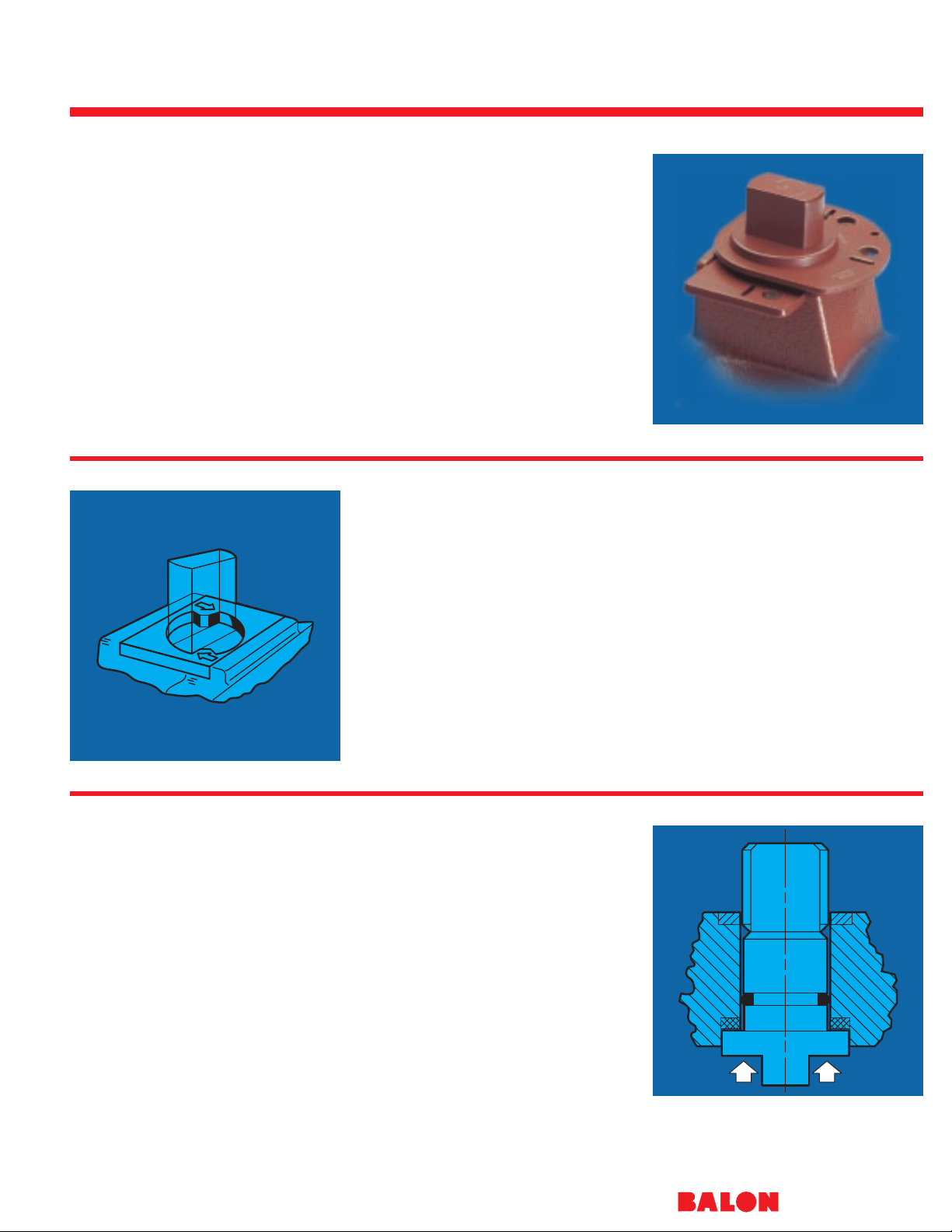
UNI-directional modification
for tank draw-down service.
While no design can prevent a
valve from freezing, Balon has
introduced a new UNI-directional
modification which reduces
the likelihood that a temporary
freeze will result in permanent
damage to the valve. This
design modification incorpo-
rates a relief hole in the
upstream side of the closed
ball. When water trapped
inside the ball cavity freezes
and expands, the relief hole
allows dissipation of the
increased internal pressure.
As shown in the diagram
on the following
page, the addition of the relief
hole renders the valve
unidirectional with the body
side of the valve positioned
upstream for proper sealing
and operation. Balon’s new
UNI-directional modification is
available as an option
within the Series S
valve line.

Ductile Iron
®
33
ITEM PART NAME MATERIAL MATERIAL STAINLESS STEEL
(STANDARD) (NACE)
1 *Handle Ductile iron Ductile iron
2 Handle bolt Standard hex bolt Standard hex bolt
3 Weather guard Polyethylene Polyethylene
4 Lock plate retainer Carbon spring steel Carbon spring steel
5 Lock plate Carbon steel - zinc plated Carbon steel - zinc plated
6 Dust cover Polyethylene Polyethylene
7 Stop plate retainer Carbon spring steel Carbon spring steel
8 Stop plate Carbon steel zinc plated Carbon steel zinc plated
9 Stem O-ring Buna Fluorocarbon
10 Stem seal TFE TFE
11 Stem Carbon steel zinc plated AISI A-316 stainless steel
ASTM A311-79 Class B annealed ASTM A-276-316
12 Ball AISI 1018 nickel chrome plated ASTM A-743-CF8M/316
annealed stainless steel
13 Ball seat Nylon (TFE optional) Nylon (TFE optional)
14 Body O-ring Buna Fluorocarbon
15 End adapter ASTM A395 class 60-40-18 ASTM A395 class 60-40-18
fully annealed fully annealed
16 Body ASTM A395 class 60-40-18 ASTM A395 class 60-40-18
fully annealed fully annealed
Material Description
RELIEF HOLE, UPSTREAM
WHEN VALVE IS CLOSED
FLOW INDICATOR FOR
UNI-DIRECTIONAL VALVES ONLY
UNI-DIRECTIONAL VALVE
Lever Operated
Threaded Construction
1" thru 4"
To 2000 PSI WP
All Series S available with 316 SS and NACE.
* This reduced port valve has a 21⁄2" bore for increased flow.
BALON SERIES “S” SCREWED END - DIM. DATA
CAT. NO.
STANDARD TRIM NACE TRIM
SIZE CARBON STEEL 316 STAINLESS PORT WP A B C D E F G H L LL M N
BALL & STEM STEEL BALL & STEM
1x1x1 1F-S62-SE 1F-S62N-SE 1 1500 3
7
⁄
8
1
15
⁄
16
1
15
⁄
16
2
1
⁄
4
2
3
⁄
8
1
⁄
2
0.340 0.685 1
7
⁄
8
2 4
3
⁄
8
2
1x1x1 1F-S92-SE 1F-S92N-SE 1 2000 4 2 2 2
1
⁄
2
2
3
⁄
8
1
⁄
2
.0.340 0.685 2
1
⁄
16
2 4
3
⁄
8
2
1x1x1 1F-S42-SE 1F-S42N-SE 1 1000 3
7
⁄
8
1
15
⁄
16
1
15
⁄
16
2
1
⁄
4
2
3
⁄
8
1
⁄
2
0.340 0.685 1
7
⁄
8
2 4
3
⁄
8
2
2x1
1
⁄
2
x2 2R-S62-SE 2R-S62N-SE 1
1
⁄
2
1500 5
1
⁄
4
2
5
⁄
8
2
5
⁄
8
3
3
⁄
8
3
5
⁄
8
3
⁄
4
0.434 0.873 3 3 7
1
⁄
4
5
2x1
1
⁄
2
x2 2R-S92-SE 2R-S92N-SE 1
1
⁄
2
2000 5
1
⁄
2
2
3
⁄
4
2
3
⁄
4
3
3
⁄
4
3
5
⁄
8
3
⁄
4
0.434 0.873 3
1
⁄
4
3
1
⁄
4
7
1
⁄
4
5
2x1
1
⁄
2
x2 2R-S42-SE 2R-S42N-SE 1
1
⁄
2
1000 5
1
⁄
4
2
5
⁄
8
2
5
⁄
8
3
3
⁄
8
3
5
⁄
8
3
⁄
4
0.434 0.873 3 3 7
1
⁄
4
5
2x1
1
⁄
2
x2 2R-S32-SE 2R-S32N-SE 1
1
⁄
2
750 5
1
⁄
4
2
5
⁄
8
2
5
⁄
8
3
3
⁄
8
3
5
⁄
8
5
⁄
8
0.434 0.873 3
1
⁄
8
3
1
⁄
8
7
1
⁄
4
5
2x2x2 2F-S32-SE 2F-S32N-SE 2 750 5
3
⁄
4
2
7
⁄
8
2
7
⁄
8
4
1
⁄
4
4
3
⁄
8
3
⁄
4
0.497 0.998 3 3 10
1
⁄
4
5
3
⁄
8
2x2x2 2F-S62-SE 2F-S62N-SE 2 1500 6 3 3 4
3
⁄
4
4
3
⁄
8
3
⁄
4
0.497 0.998 3
3
⁄
4
3
3
⁄
4
10
1
⁄
4
5
3
⁄
8
2x2x2 2F-S42-SE 2F-S42N-SE 2 1000 5
3
⁄
4
2
7
⁄
8
2
7
⁄
8
4
1
⁄
4
4
3
⁄
8
3
⁄
4
0.497 0.998 3 3 10
1
⁄
4
5
3
⁄
8
2x2x2 2F-S92-SE 2F-S92N-SE 2 2000 6 3 3 4
3
⁄
4
4
3
⁄
8
3
⁄
4
0.497 0.998 3
1
⁄
4
3
1
⁄
4
10
1
⁄
4
5
3
⁄
8
*3x2
1
⁄
2
x3 3R-S42-SE 3R-S42N-SE 2
1
⁄
2
1000 7
5
⁄
8
3
13
⁄
16
3
13
⁄
16
5
1
⁄
4
5
1
⁄
4
1
1
⁄
16
0.622 1.248 4
1
⁄
8
4 16 5
3
⁄
4
3x2x3 3R-S62-SE 3R-S62N-SE 2 1500 7
1
⁄
4
3
5
⁄
8
3
5
⁄
8
5 4
3
⁄
8
3
⁄
4
0.497 0.998 4
1
⁄
2
4
1
⁄
2
10
1
⁄
4
5
3
⁄
8
3x3x3 3F-S32-SE 3F-S32N-SE 3 750 8 4 4 6 5
3
⁄
4
7
⁄
8
0.747 1.373 4
1
⁄
8
4 20 6
3
⁄
4
3x2x3 3R-S32-SE 3R-S32N-SE 2 750 7
1
⁄
4
3
1
⁄
2
3
3
⁄
4
4
1
⁄
2
4
3
⁄
8
3
⁄
4
0.497 0.998 4
1
⁄
8
4 10
1
⁄
4
5
3
⁄
8
3x3x3 3F-S42-SE 3F-S42N-SE 3 1000 8
3
⁄
4
4
3
⁄
8
4
3
⁄
8
6 5
3
⁄
4
7
⁄
8
0.747 1.373 4
1
⁄
2
4
1
⁄
2
20 6
3
⁄
4
4x3x4 4R-S32-SE 4R-S32N-SE 3 750 8
3
⁄
4
4
3
⁄
8
4
3
⁄
8
6 5
3
⁄
4
7
⁄
8
0.747 1.373 5
9
⁄
16
5
1
⁄
4
20 6
3
⁄
4
4x3x4 4R-S42-SE 4R-S42N-SE 3 1000 8
3
⁄
4
4
3
⁄
8
4
3
⁄
8
6 5
3
⁄
4
7
⁄
8
0.747 1.373 5
9
⁄
16
5
1
⁄
4
20 6
3
⁄
4
4x4x4 4F-S22-SE 4F-S22N-SE 4 500 9
3
⁄
8
4
11
⁄
16
4
11
⁄
16
7
1
⁄
2
6
3
⁄
8
1
1
⁄
16
0.747 1.373 5
9
⁄
16
5
1
⁄
4
20 7
3
⁄
8
Dimensions
BALON SERIES “S” GROOVED END - DIM. DATA
CAT. NO.
STANDARD TRIM NACE TRIM
SIZE
CARBON STEEL 316 STAINLESS
PORT WP A B C D E F G H L LL M N
BALL & STEM STEEL BALL & STEM
2x11⁄2x2 2R-S32-GE 2R-S32N-GE 11⁄2750 51⁄8211⁄1627⁄1633⁄835⁄
8
5
⁄80.434 0.873 23⁄823⁄871⁄45
3x2x3 3R-S32-GE 3R-S32N-GE 2 750 7
1
⁄431⁄233⁄441⁄243⁄
8
3
⁄40.497 0.998 31⁄231⁄2101⁄453⁄
8
4x3x4 4R-S32-GE 4R-S32N-GE 3 750 87⁄841⁄243⁄86 53⁄
4
7
⁄80.747 1.373 41⁄241⁄220 63⁄
4
* Balon valves are designed to be operated
with a standard open-end wrench.
Handle and Handle Bolt are optional.
WP is for valve equipped with standard nylon
seats. See Chart on page 43 TFE ratings.

Series S Screwed End Carbon Steel
®
34
ITEM PART NAME MATERIAL MATERIAL STAINLESS STEEL
(STANDARD) (NACE)
1 Handle* Ductile iron Ductile iron
2 Handle bolt Standard hex bolt Standard hex bolt
3 Weather guard Polyethylene Polyethylene
4 Lock plate retainer Carbon spring steel Carbon spring steel
5 Lock plate Carbon steel - zinc plated Carbon steel - zinc plated
6 Dust cover Polyethylene Polyethylene
7 Stop plate retainer Carbon spring steel Carbon spring steel
8 Stop plate Carbon steel zinc plated Carbon steel zinc plated
9 Stem O-ring Buna Fluorocarbon
10 Stem seal TFE TFE
11 Stem Stress proof zinc plated AISI A-316 stainless steel
ASTM A311-79 Class B annealed ASTM A-276-316
12 Ball AISI 1018 nickel chrome plated ASTM A-743-CF8M
annealed stainless steel
13 Ball seat Nylon-Acetal Nylon-Acetal
14 Body O-ring Buna Fluorocarbon
15 End adapter ASTM 216 grade WCB annealed ASTM 216 grade WCB annealed
carbon steel carbon steel
16 Body ASTM 216 grade WCB annealed ASTM 216 grade WCB annealed
carbon steel carbon steel
Material Description Lever Operated
Threaded Construction
To 3000 PSI WP
BALON SERIES “S” SCREWED END - DIM. DATA
CAT. NO.
STANDARD TRIM NACE TRIM
SIZE CARBON STEEL 316 STAINLESS PORT WP A B C D E F G H L LL M N
BALL & STEM STEEL BALL & STEM
1x1x1 1F-S93-SE 1F-S93N-SE 1 2500 4 2 2 23⁄423⁄
8
1
⁄20.340 .685 21⁄162 43⁄82
1x1x1 1F-S03-SE 1F-S03N-SE 1 3000 4 2 2 23⁄423⁄
8
1
⁄20.340 .685 21⁄162 43⁄82
2x11⁄2x2 2R-S93-SE 2R-S93N-SE 11⁄22500 51⁄223⁄423⁄441⁄435⁄
8
3
⁄40.434 .873 31⁄231⁄271⁄45
2x11⁄2x2 2R-S03-SE 2R-S03N-SE 11⁄23000 51⁄223⁄423⁄441⁄435⁄
8
3
⁄40.434 .873 31⁄231⁄271⁄45
2x2x2 2F-S03-SE 2F-S03N-SE 2 3000 6 31⁄827⁄847⁄843⁄
8
3
⁄40.497 .998 31⁄231⁄2101⁄453⁄
8
2x2x2 2F-S93-SE 2F-S93N-SE 2 2500 6 31⁄827⁄847⁄843⁄
8
3
⁄40.497 .998 31⁄231⁄2101⁄453⁄
8
Dimensions
All Series S available with 316 SS and NACE.
* Balon valves are designed to be operated
with a standard open-end wrench.
Handle and Handle Bolt are optional.

Series S Screwed End Stainless Steel
®
35
ITEM PART NAME MATERIAL STAINLESS STEEL
(STANDARD NACE)
1 Handle* Ductile iron
2 Handle bolt Standard hex bolt
3 Weather guard Polyethylene
4 Lock plate retainer Stainless steel
5 Lock plate Stainless steel
6 Dust cover Polyethylene
7 Stop plate retainer Stainless steel
8 Stop plate Stainless steel
9 Stem O-ring Fluorocarbon
10 Stem seal TFE
11 Stem AISI A-316 stainless steel annealed ASTM A-276-316
12 Ball ASTM A-743-CF8M/316 annealed stainless steel
13 Ball seat Acetal-nylon
14 Body O-ring Fluorocarbon
15 End adapter ASTM A351-CF8M annealed stainless steel
16 Body ASTM A351-CF8M annealed stainless steel
Material Description Lever Operated
Threaded Construction
To 3000 PSI WP
BALON SERIES “S” SCREWED END - DIM. DATA
CAT. NO.
NACE TRIM
SIZE 316 STAINLESS PORT WP A B C D E F G H L LL M N
STEEL BALL & STEM
1x1x1 1F-S95N-SE 1 2000 4 2 2 23⁄423⁄
8
1
⁄20.340 .685 21⁄162 43⁄82
1x1x1 1F-S05N-SE 1 3000 4 2 2 23⁄423⁄
8
1
⁄20.340 .685 21⁄162 43⁄82
2x11⁄2x2 2R-S95N-SE 11⁄22000 51⁄223⁄423⁄443⁄435⁄
8
3
⁄40.434 .873 31⁄231⁄271⁄45
2x11⁄2x2 2R-S05N-SE 11⁄23000 51⁄223⁄423⁄441⁄435⁄
8
3
⁄40.434 .873 31⁄231⁄271⁄45
2x2x2 2F-S95N-SE 2 2000 6 31⁄827⁄847⁄843⁄
8
3
⁄40.497 .998 31⁄231⁄2101⁄453⁄
8
2x2x2 2F-S05N-SE 2 3000 6 31⁄827⁄847⁄843⁄
8
3
⁄40.497 .998 31⁄231⁄2101⁄453⁄
8
Dimensions
* Balon valves are designed to be operated
with a standard open-end wrench.
Handle and Handle Bolt are optional.

Series LM Screwed End
®
36
A Simple Superior Valve
The Series LM valve is a low
cost route to quality. Since
introduced, it has become a
favorite valve for drip service,
meter hookups, blow down,
emergency shutdown, and
anywhere a dependable
quarter turn block valve is
needed.
Machined from barstock, this
valve is priced low enough for
low pressure service, but the
rugged bolted construction
assures strength and rigidity
for high pressure service in the
plant and in the field.
The wide ranging capability of
this valve is enhanced by the
316 stainless steel ball and
stem which are standard in all
Series LM valves.
General Features
■ Locking device and handle
■ Socket head bolting for
strength.
■ Multi-seal seats standard.
■ Smooth uninterrupted
external surfaces - no
corrosion traps.
■ Symmetry of design allows
versatile in-line position
or placement.
■ Low torque operation at
full rated pressure.
■ Nylon seats standard with
TFE optional (see chart
page 42).
■ NACE available.

Carbon Steel
®
14
15
BALON 3000 PSI WP - SERIES “LM” BALON BALL VALVE - DIM. DATA
CAT. NO.
STANDARD TRIM NACE TRIM
SIZE
316 STAINLESS 316 STAINLESS
PORT WP A B C D E F G
STEEL BALL & STEM STEEL BALL & STEM
1
⁄4x 3⁄8x 1⁄4LM-02362 LM-02362-N
3
⁄83000 11⁄411⁄831⁄215⁄
8
5
⁄
8
21⁄
4
1
⁄
4
1
⁄2x 3⁄8x 1⁄2LM-05361 LM-05361-N
3
⁄4x 3⁄4x 3⁄4LM-07362 LM-07362-N
3
⁄43000 2 113⁄1647⁄821⁄
4
1 35⁄
8
3
⁄
8
1 x 3⁄4x 1 LM-10361 LM-10361-N
All Series LM available with NACE trim.
All Series LM available with NACE trim.
Dimensions
ITEM PART NAME MATERIAL DESCRIPTION MATERIAL DESCRIPTION
(STANDARD) (NACE)
1 Weather guard Polyethylene Polyethylene
2 Stem nut ANSI B18.8.2-179 zinc plated ANSI B18.8.2-179 zinc plated
3 Lock plate AISI: 1008 HR steel zinc plated AISI: 1008 HR steel zinc plated
4 Handle AISI: 1008 HR steel zinc plated AISI: 1008 HR steel zinc plated
5 Stem washer Acetal Acetal
6 Stop Pin ANSI B18.8.2-179 zinc plated ANSI B18.8.2-179 zinc plated
7 Stem O-ring Buna Fluorocarbon
8 Stem seal TFE TFE
9 Stem AISI: Type 316 stainless steel AISI: Type 316 stainless steel
10 Body AISI: 1215 zinc plated AISI: 1018 zinc plated
11 Ball seat Nylon (TFE optional) Nylon (TFE optional)
12 Ball AISI: 316 stainless steel AISI: 316 stainless steel
13 Body seal Buna Fluorocarbon
14 End adapter AISI: 1215 zinc plated AISI: 1018 zinc plated
15 Body bolts ANSI B18.3-1982 ANSI ASTM
ASTM A/574-1980 A-193-B7M
Material Description
Lever Operated
Bolted Body Construction
3000 PSI W.P.
37
* Handle and locking device standard on all Series LM ball valves.
WP is for valve equipped with standard nylon seats. See Chart on page 43 for TFE ratings.

Series LS Screwed End
®
38
The Series LS solid stainless
steel ball valve has been
designed to stand up consis-
tently against the very tough-
est of applications. It is intend-
ed for services such as CO2,
H2S, saltwater, and other
severely corrosive
media.
Made of stainless steel
throughout (including balls,
stems, and handles) the LS is
available in both 2000 psi and
3000 psi working pressures.
They are maintenance-free
and require no field lubrication
for the life of the valve.
The LS features an exclusive
patented design to inhibit the
loosening of the end adapter.
The adapter end of the body is
machine-crimped at each
wrench flat of the end adapter
itself, thus securing the
adapter to the body.
General Features
■ All metal components of
stainless steel.
■ Locking device and handle.
■ Multi-seal seats standard.
■ Low torque operation at full
rated pressure.
■ Machine-crimped tailpiece
■ NACE standard

Stainless Steel
®
39
Lever Operated
Threaded Construction
2000-3000 PSI W.P.
BALON SERIES “LS” SCREWED END BALON BALL VALVE - DIM. DATA
SIZE CAT. NO. PORT W.P. A B C D E
1
⁄4x 3⁄8x 1⁄
4
LS-02592
3
⁄
8
3000 1.375 1.125 31⁄
2
15⁄
8
25⁄
8
1
⁄2x 3⁄8x 1⁄
2
LS-05591
3
⁄
8
3000 1.375 1.438 31⁄
2
15⁄
8
3
1
⁄2x 3⁄8x 1⁄
2
LS-05561
3
⁄
8
2000 1.375 1.125 31⁄
2
15⁄
8
21⁄
2
3
⁄4x 3⁄4x 3⁄
4
LS-07592
3
⁄
4
3000 2.125 1.750 47⁄
8
21⁄
4
33⁄
4
1 x 3⁄4x 1 LS-10591
3
⁄
4
3000 2.125 2.000 47⁄
8
21⁄
4
41⁄
8
1 x 3⁄4x 1 LS-10561
3
⁄
4
2000 2.125 1.875 47⁄
8
21⁄
4
33⁄
4
ITEM PART NAME MATERIAL DESCRIPTION (NACE STANDARD)
1 Weather guard Polyethylene
2 Stem nut Stainless steel
3 Lock plate Stainless steel
4 Handle Stainless steel
5 Stem washer Acetal
6 Stop pin Stainless steel
7 Stem O-ring Buna
8 Stem seal TFE
9 Stem AISI: 316 stainless steel
10 Body AISI: 316 stainless steel
11 Ball seat Nylon (TFE optional)
12 Ball AISI: 316 stainless steel
13 Body seal Fluorocarbon
14 Adapter AISI: 316 stainless steel
Material Description
* Handle and locking device standard
on all Series LS ball valves.
WP is for valve equipped with standard nylon seats. See Chart on page 43 for TFE ratings.
13
14

Balon Installations
®
40

Technical and
Engineering Data
WITH MULTI-SEAL
Patented

Media and Application Guide
42
®
This BALON “Media and Application
Guide” provides assistance to the
engineer in selecting the best material
for a particular service. The final
selection of materials however, requires
the judgment of the user because it may
be necessary to sacrifice certain physical properties of a material to take better advantage of others.
Information contained in the following
chart is believed to be reliable and is
intended to be used by trained
personnel at their own discretion and
risk. Due to many factors which affect
the rate of corrosion, we suggest that
final acceptability be established by test
under actual operating conditions.
Ratings are based on media at ambient
temperatures except as noted.
VALVE SEAT and SEAL
MATERIAL MATERIAL
MEDIA*
Carbon Ductile 316 SS Buna-N Viton Nylon TFE
Steel Iron
VALVE SEAT and SEAL
MATERIAL MATERIAL
MEDIA*
Carbon Ductile 316 SS Buna-N Viton Nylon TFE
Steel Iron
Air EEEEEEE
Alcohols G G E E E F E
Amines (Conc.) E E E U U E E
Ammonia, Anhydrous E G E F U E E
– Aqueous E E E F U G E
– Solutions G G E F U G E
Benzene or Benzol G G E U E E E
Brines F F G E E E E
Bunker Oils (Fuels) G G E E E E E
Butane E E E E E E E
Carbolic Acid (Phenol) U U G U G U E
Carbon Dioxide, Dry E F E G G G E
Carbonic Acid U U G G E E E
Carbon Tetrachloride, Dry F F E U E E E
– Wet U U G U E E E
Carbonated Water G G E E E G E
Crude Oil, Sweet E E E E E E E
– Sour G G E F G G E
Diethylamine (DEA) E E E U U E E
Diesel Fuels E E E E E E E
Dowtherm A and E G G E U E E E
Drilling Mud G G E E E E E
Ethane E E E E E E E
Ethylene E E E U E E E
Ethylene Glycol G G G E E G E
Fuel Oil G G E E E E E
Gas, Manufactured G G G E E E E
– Natural G G E E E E E
– Odorizers G G E U E G E
– Sour G G E F E E E
Gasoline, Leaded E G E G E E E
– Unleaded E G E F E E E
– Aviation E G E G E E E
– Motor E G E F E E E
Glycols G G G E E G E
Heptane E E E E E E E
Hexane E E E E E E E
Hydraulic Oil
– Petroleum Base E E E E E E E
– Phosphate Base E E E U E E E
Hydrochloric Acid,
Air Free U U U F E U E
Hydrofluoric Acid U U U U U U F
Hydrogen Gas G G E E E E E
Hydrogen Sulfide,Dry(Conc.) G G E F F E E
– Wet (Conc.) F U G U F E E
Illuminating Gas E E E E E E
Iso-Octane E G E E E E E
Isopropyl Alcohol G G G G E G E
– Ether E G E G U E E
JP-4 Fuel E E E E E E E
JP-5 Fuel E E E E E E E
JP-6 Fuel E E E E E E E
Kerosene G G E E E E E
Liquefied Pet. Gas (LPG) G G G E E E E
Lubricating Oil E E E E E E E
Mercaptan (Conc.) G G E F E G E
Methane E E E E E E E
Muriatic Acid U U U G E U E
Naphtha G G E G E E E
Naphthalene E G E U E E E
Natural Gas E E E E E E E
Nitrogen E E E E E E E
Oil, Animal E E E E E E
– Cottonseed F F G E E E E
– Fish G G E E E E E
– Fuel G G E E E E E
– Lube E E E E E E E
– Mineral G G E E E E E
– Petroleum, Refined E G E E E E E
Oil-Water Mixtures E E E E E E E
Paraffin G G E G E E E
Pentane G G E U E E E
Producer Gas G G G E E E E
Propane E E E E E E E
Propyl Alcohol E E E E E E E
Propylene Glycol E E E E E F E
Sea Water U U E E E E E
Sodium Acetate G G G G U G E
– Hydroxide, Cold, 20% E E E G G E E
– Hydroxide, Hot, 20% F F G G G G E
– Hydroxide, Cold, 50% G G G F F F F
– Hydroxide, Hot, 50% G G G U F U F
– Hydroxide, Cold, 70% F F G U F F
– Hydroxide, Hot, 70% G F G U F U
Steam (212°F) E E E U U U E
Stoddard Solvent G G G E E G E
Sulfur Dioxide (Dry) G G E U U F E
Sulfuric Acid, 0-7% F F G F E G E
– 20% U U F U E U E
– 50% U U U U E U E
– 100% U U U U E U E
Toluene or Toluol E E E U E E E
Water, Distilled, Aerated U U E E G E E
– Fresh F F E E E E E
– Sea U U E E E E E
Wax Emulsions E G E E E E E
Waxes E E E E E E E
Xylene, Dry E E E U E E E
E – Excellent G – Good F – Fair U – Unsatisfactory BLANK – Insufficient Data
* Consult Oklahoma City for compatibility of Aluminum Bronze material.

Seat Pressure - T emperature Ratings
43
®
4000
3000
2000
1800
1600
1400
1200
1000
800
600
400
200
0
100° 200° 300° 400° 500°
PRESSURE DIFFERENTIAL
PSI — VALVE CLOSED
ACETAL
NYLON
TEMP. F°
2000
1800
1600
1400
1200
1000
800
600
400
200
0
100° 200° 300° 400° 500°
PRESSURE DIFFERENTIAL
PSI — VALVE CLOSED
TEFLON*
TEMP. F°
NYLON / ACETAL
* Reg. DuPont
PEEK
2200
220° 350°
250°
1⁄4" Full — 2" Reg.
2" Full — 3" Reg.
3" Full — 4" Reg.
4" Full — 6" Reg.
6" Full — 8" Reg.

Balon Flow Data Carbon Steel Flanged V alves
44
®
Cv Ratings of Regular Port Valve
Balon valves are designed with the ball
center offset from the valve center.
This permits optimum castability of the
body and the adapter, and results in
better castings. The longer taper in the
adapter also improves flow characteristics. The direction in which the valve is
installed in the line has an effect on flow
capacity.
The calculated figures listed below
illustrate this effect. It should be noted
that actual performance cannot be
expected to duplicate tabulated figures
due to the effects of adjacent fittings,
flange alignment, pipe size and
roughness, etc.
FLANGED VALVE Cv
CLASS CLASS CLASS CLASS CLASS CLASS
SIZE 150 300 400 600 900 1500
2 x 11⁄
2
139 128 SEE 116 117 117
21⁄2x 2 256 240 CLASS 202 - -
3 x 2 235 215 600 200 274 4 x 3 518 537 512 482 - 6 x 4 821 987 - 1170 - 8 x 6 2469 3162 - 3396 - -
FLANGED VALVE Cv
CLASS CLASS CLASS CLASS CLASS CLASS
SIZE 150 300 400 600 900 1500
2 x 11⁄
2
118 119 SEE 107 114 114
21⁄2x 2 212 208 CLASS 191 - -
3 x 2 178 190 600 180 255 4 x 3 451 462 509 430 - 6 x 4 741 802 - 964 - 8 x 6 2360 2732 - 2933 - -
Cv Ratings of Full Bore Valve
Depending upon pipe schedule with
which they are used, Balon full bore
valves have bore sizes exceeding or
nearly equaling the pipe inside diameter. The best method of computing
system pressure losses is to consider
the valve an equivalent length of pipe as
shown below.
Using the Cv method of rating full bore
valves does not provide good accuracy.
The reason for this is that Cv tests do
not provide valid data until the measured pressure drop equals at least 2
psi. In the relatively short length
involved in a valve, extremely high
velocities are required to generate that
pressure drop. At these high velocities
(which are well beyond those used in
industry) other effects, such as vibration
and pulsation are then created by
“super turbulent” flow. The net results
are Cv ratings which are lower than
would be derived if pressure losses
could be consistently measured at
velocities in the usable range.
EQUIVALENT. LENGTH OF PIPE - FEET
SIZE CLASS 150 CLASS 300 CLASS 600 CLASS 900 CLASS 1500
1 .42 - .71 .83 .83
11⁄
2
.53 .62 .79 - -
2 .58 .71 .96 1.21 1.21
21⁄
2
.62 .79 1.09 - 3 .66 .93 1.17 - 4 .75 1.00 1.42 - 6 .88 1.32 1.83 - -

Actuator Sizing
45
®
Because the actuator sizing is so critical
to the proper operation and life of a ball
valve, we have chosen not to publish
torque values. Misinterpretation of
manual torque data can lead to
undersizing, while misinterpretation of
factored torque values can mislead as
to ease of manual operation.
Furthermore, type of service conditions
can significantly alter standard torque
requirements. Balon valves have been
recognized for years as a very easy to
operate valve. We will be glad to
provide sizing information upon request
through one of our field representatives
or from our Oklahoma City
headquarters.
API........................... (AMERICAN PETROLEUM INSTITUTE)
API 6FA................... FIRE TEST FOR SOFT-SEATED
VALVES
API 5B..................... INSPECTION OF THREADS
API 6D..................... PIPELINE VALVES, END CLOSURES,
CONNECTORS AND SWIVELS
API-Q1.................... QUALITY PROGRAMS
API-594....................WAFER CHECK VALVES
ANSI........................ (AMERICAN NATIONAL STANDARD
INSTITUTE)
ANSI-B.................... 16.5 - PIPE FLANGES AND FLANGED
FITTINGS
ANSI-B.................... 16.10 - FACE-TO-FACE END-TO-END
DIMENSIONS
ANSI-B.................... 16.42 DUCTILE IRON PIPE FLANGES
AND FLANGED FITTINGS
ANSI-B.................... 16.34 - VALVES - FLANGED END,
THREADED AND BUTT WELD
ANSI-B.................... (B1.20.1) - PIPE THREADS GENERAL
PURPOSE (INCH)
MSS.........................(MANUFACTURERS
STANDARDIZATION SOCIETY)
MSS-SP6.................STANDARD FINISHES FOR CONTACT
FACES OF PIPE FLANGES AND
CONNECTION END FLANGES OF
Standards and Specifications
Balon utilizes the following standards in
the manufacture of ball valves. It should
be noted that not all styles, configura-
tions and materials used in Balon
Valves meet all of these standards in
their entirety.
User should, therefore, specify a given
standard if there is a need to assure
total compliance with a given standard.
Balon valves are manufactured to the following standards and specifications, among others.
VALVES AND FITTINGS
MSS-SP25...............STANDARD MARKING SYSTEM
FOR VALVES, FITTINGS, FLANGES
AND FITTINGS
MSS-SP72...............BALL VALVES WITH FLANGED OR
BUTT WELDING ENDS FOR GENERAL
SERVICE
MSS-SP82...............VALVE PRESSURE TEST METHODS
MSS-SP84...............STEEL VALVES-SOCKET WELDING
AND THREADED ENDS
NACE MR-01-75..... SULFIDE STRESS CRACKING,
RESISTANT METALLIC MATERIAL
FOR OILFIELD EQUIPMENT (NACE
MATERIALS ARE OPTIONAL AND
MUST BE SPECIFIED ON PURCHASE
ORDERS)
U.S. COAST GUARD
ACCEPTED AS AN APPROVED
AFFIDAVITED MANUFACTURER
OF VALVES FOR USE ON COAST
GUARD INSPECTED AND CERTIFIED
EQUIPMENT (46 CFR 56.07-5)
ASSOCIATION OF AMERICAN RAILROADS
TANK CARS

Identification Key
Nominal Pipe Size
2 R-F 9 2 N-S E
Balon
Screwed End/Grooved End
Series F, S, UNI
Balon
Flanged End, Weld End
Series F, US
Nominal Pipe Size
2 R-F 1 3 N-R F
NOTE: For Unidirectional valve
substitute UNI for SE or GE.
Port Size
R Regular or Reduced Port
F Full Port
Valve Series
S Screwed Body
F Bolted Body
Valve Material
2 Ductile Iron
3 Carbon Steel
4 Aluminum Bronze
5 Stainless Steel
Trim (Ball & Stem Material)
Not used if Carbon Steel standard
N NACE (Stainless Steel ball & stem)
End Connections
SEScrewed End
GEGrooved End
Valve Working Pressure
2 500 PSI WP
3 750 PSI WP
4 1000 PSI WP
6 1500 PSI WP
9
2000 PSI WP or
2500 PSI WP 2" Reg. Carbon Steel
0 3000 PSI WP
Port Size
R Regular or Reduced Port
F Full Port
Valve Series
F Flanged End
US Weld End,
Weld X Flange
Valve Working Pressure
1 ANSI 150 285 WP Carbon Steel
Ductile Iron RF 250 WP
FF 200 WP
3 ANSI 300 740 WP Carbon Steel
Ductile Iron RF 640 WP
6 ANSI 600 1480 WP
9 ANSI 900 2220 WP
0 ANSI 1500 3705 WP
Valve Material
2 Ductile Iron
3 Carbon Steel
Trim (Ball & Stem Material)
Not used if Carbon Steel standard
N NACE (Stainless Steel ball & stem)
End Connection
RFRaised Face
RJRing Type Joint
BWButt Weld
WFWeld X Flange
FFFlat Face
(Ductile Only)
Balon
Screwed End
Series L
“L” Series
L M-02 3 6 2-N
Not used if Carbon Steel
N Carbon Steel NACE Trim
Valve Series
M Carbon Steel Series
S Stainless Steel Series
Valve Material
3 Carbon Steel
5 Stainless Steel
NOTE: For any valves not listed please consult factory.
Port Size
1 Regular Port
2 Full Port
Nominal Pipe Size
02 1/4 NPT
05 1/2 NPT
07 3/4 NPT
10 1 NPT
Valve Working Pressure
6 3000 PSI WP Carbon Steel
2000 PSI WP Stainless Steel
9 3000 PSI WP Stainless Steel
46
®

T erms and Conditions
47
®
PRICES AND DISCOUNTS
All published prices and discounts are subject to change
without notice.
LITERATURE
Published information such as catalogs, brochures, or other
literature is subject to change without notice.
FREIGHT ALLOWANCE
All shipments are F.O.B. at Balon’s plant in Oklahoma City,
with full freight allowed on shipments of 1000 pounds or more
to one (1) destination within the continental United States or
Canada (excluding Alaska). Freight allowances are via
cheapest way. For customers designating a more costly
transportation, a charge will be made for the difference
between it and the cheapest way.
DELIVERY
Estimated shipping dates are based as accurately as possible
on current conditions in effect at time of estimate. Shipping
Dates appearing on acknowledgements, or offered in any
other manner, are approximate, and order will be shipped as
soon as completed and ready for shipment, unless otherwise
agreed to in writing. Balon assumes no liability for failure or
delay in delivery due to acts of God, difference with workmen,
local labor shortages, fire, flood or other casualty, government
regulations, or edicts, shortages or failure of raw material,
supplies, fuel, power or transportation, breakdown of equipment or any other causes beyond Balon’s reasonable control.
CANCELLATION
Firm orders which have been accepted and entered shall not
be subject to cancellation except by permission of and on the
terms prescribed by Balon Corporation.
RETURN POLICY
Unused products may be returned only upon written consent
of Balon’s Oklahoma City office. Credit will be issued only on
products which are received by Balon within one year after
the date of original purchase and returned by prepaid freight
at Buyer’s expense together with a copy of Balon’s Return
Authorization Form and documents which verify the original
purchase order number and original invoice number. A
deduction will be made for any cost incurred by Balon in
restoring products to saleable condition. Credit may be used
only for the purchase of merchandise and is not subject to
cash reimbursements or cash payments.
LIMITED WARRANTY
Balon warrants its products against defects in material and
workmanship for one year from the original date of shipment.
In the event a Balon product is defective in a manner covered
by this Limited Warranty, Balon, at its option, will either
replace or repair the product. Alternatively, if any stipulated
remedy shall fail in its essential purpose, Balon shall refund
the purchase price of such product as the sole and exclusive
remedy for any and all claims whether in contract, strict
liability, tort or otherwise. THIS LIMITED WARRANTY IS IN
LIEU OF ANY OTHER WARRANTIES AND REMEDIES,
EXPRESS OR IMPLIED. BALON MAKES NO OTHER
WARRANTIES, EXPRESS OR IMPLIED, INCLUDING ANY
WARRANTY OF FITNESS FOR A PARTICULAR PURPOSE,
MERCHANTABILITY OR NON-INFRINGEMENT. IN NO
EVENT SHALL BALON BE LIABLE FOR ANY DAMAGES OF
ANY KIND OR NATURE, INCLUDING BUT NOT LIMITED TO
ANY CONSEQUENTIAL, EXEMPLARY, INDIRECT, INCIDENTAL, PUNITIVE OR SPECIAL DAMAGES AND IN NO EVENT
SHALL BALON’S LIABILITY EXCEED THE PURCHASE
PRICE OF THE PRODUCT(S). Products which have been
subjected to abuse, alteration, misuse, neglect or unauthorized repair or installation, as determined solely by Balon, are
not covered by this Limited Warranty. All alterations,
additions, improvements or attachments to the product(s),
not authorized in writing and signed by an authorized officer
of Balon shall be deemed to be a waiver of this Limited
Warranty and shall render this Limited Warranty null and void.
This Limited Warranty may only be altered, amended,
expanded, modified, rescinded or terminated in writing signed
by an authorized officer of Balon.

Balon Installations
48
®

Balon Installations
49
®

© 2002 Balon Corp.
5M/0502
3245 S. HATTIE • OKLAHOMA CITY, OKLAHOMA 73129 • (405) 677-3321
E-mail: BALON@BALON.COM • www.balon.com
 Loading...