


INSTALLATION AND OPERATOR’S MANUAL
Balmar’s Smartgauge™ battery monitoring system
provides accurate dependable information about
battery condition, without the need for shunts and
complicated programming. Simply select the battery
program that most closely matches your battery
technology.
The Smartgauge™ features Voltage and State of
Charge (SoC%) displays, and can be used to
provide alarms for low battery voltage and capacity.
As with all electrical components, take time to read
and follow the instructions provided in this manual.
Failure to do so could result in damage to the
Smartgauge™ and/or your electrical system.
VOLTS
Set
Emergency
Connect
Smartgauge™
BATTERY MONITOR
Smartgauge
SmartBank
SmartBank
PGM/Battery 2
Alarm
STATUS
Select
BATT 2
Exit
Advanced Battery
Monitor System
™
SECTION TOPIC PAGE
CONTENTS
1.0 Introduction ....................................................................................................... ....... Page 2
2.0 Quick Start Guide ............................................................................................. ........ Page 3
2.1 Smartgauge Installation Basics ...................................................................... ........ Page 5
2.2 Important Installation Notes......................................................................... ............ Page 5
3.0 Initial Smartgauge Start Up ................................................................................ ..... Page 6
3.1 Determining Battery Charge Status......................................................................... Page 6
3.2 Calibrating Battery Charge Status................................................................... ........ Page 7
3.3 Power Up After Power Loss ......................................................................... ........... Page 7
4.0 Basic Monitor Use .............................................................................................. ...... Page 8
4.1 Set Up Menu............................................................................................................... Page 9
4.2 Set Up Mode – Battery Type ................................................................ .................... Page 9
4.3 Set Up Mode – Charge Status ............................................................ .................. Page 10
4.4 Alarm Functions .......................................................................... ........................... Page 10
4.5 Defeating Error Codes ................................................................. ......................... Page 13
4.6 Set Up Display Behavior......................................................... ................................ Page 14
4.7 Set Up Display Brightness ............................................................... ..................... Page 14
4.8 Set Up Menu Lock ........................................................................... ....................... Page 15
5.0 Error Codes.............................................................................................................. Page 15
6.0 Reset to Factory Defaults ............................................................. ......................... Page 16
7.0 Alarm Outputs .............................................................................. .......................... Page 17
8.0 Alarm Notes ........................................................................ .................................... Page 17
9.0 Addendum................................................................................................................ Page 17
10.0 Specications .................................................................................... ..................... Page 18
11.0 Warranty ........................................................................................ .......................... Page 19
12.0 Smartgauge Display Flowcharts................................................ ............................ Page 19
BALMAR LLC. MARYSVILLE, WA 98271 USA – WWW.BALMAR.NET – +1-360-435-6100
©2016 Balmar LLC. Reproduction is forbidden without permission
QF-137 Rev B

SECTION 1.0 – INTRODUCTION PAGE 2
The Smartgauge™ battery monitor employs advanced battery monitoring techniques to provide
battery voltage and State of Charge (SoC%) information in a manner that’s both highly accurate
and self correcting. Smartgauge™ is unconventional – please read this manual fully to understand
how and why it works.
Further technical support can be obtained from Balmar Customer Service at +1-360-435-6100.
Features:
• House (Primary) Battery Voltage
• House (Primary) Battery State of Charge
• Engine (Secondary) Battery Voltage
• High/Low Battery Voltage alarms for each battery
• High/Low State of Charge alarm for House (Primary) battery
• Bright LED daylight readable display
• Volt free alarm contact for ring external alarms, relays etc
How the Smartgauge™ Works
Conventional battery monitors count amp hours in/out of the battery to determine the battery’s State
of Charge (SoC). This method is inherently inaccurate due to the State of Charge of the battery not
necessarily being linked to the amount of energy a battery can deliver (due to temperature, how quickly
the battery was charged/discharged, battery age, and other outside factors). Unless the battery monitor
is regularly reset (either automatically by fully charging the battery or manually reset by the user), the
reading error will compound (known as synchronization error).
In most battery monitors, a shunt is used to monitor amperage in or out of the battery. Unfortunately, in
many cases shunts can be incorrectly installed, and inaccurate amperage readings occur.
Smartgauge™ uses just two wires to monitor the battery. Through these wires, we use proprietary
test methods to generate data. This data is then compared to detailed computerized battery models.
Smartgauge™ compares real world data with those models to generate information on the battery’s
State of Charge. In independent testing Smartgauge™ was found to be within 5% accuracy at all times.
Highly accurate SoC information not only allows you to condently make decisions about how you use
your electrical system, it also allows you to automate certain functions – like load shedding or generator
start/stop.
Smartgauge™ uses a self correcting algorithm to determine battery State of Charge, so over time
it actually becomes more and more accurate. This self correction also means that Smartgauge™
automatically adjusts for battery degradation as the batteries are repeatedly cycled. Smartgauge™
needs to see 2-3 charge/discharge cycles to synchronize with the batteries.
CAUTIONS AND WARNINGS
CAUTION: Statements Identied with the word CAUTION relate to practices that may
damage Smartgauge
WARNING: Statements identied with the word WARNING relate to practices that may
cause injury or death.

PAGE 3
SECTION 1.0 – INTRODUCTION
CAUTION & WARNING: This manual is written with the intention for use by a qualied electrical
technician. It does not identify normal practices or procedures that would be expected of a qualied
electrician. Please review and comply with any installation and/or safety standards, such as those
provided by ABYC or other agencies regulating electrical system safety. Please review the instruction
manuals for any equipment or tools that you may be using to complete this installation.
CAUTION: Please fully review this manual before commencing installation.
Certicate of Conformity:
Declaration of Conformity
Smartgauge™ is in compliance with the requirements of EU Electromagnetic Compatibility (EMC)
Directive 89/336/EEC. Smartgauge™ complies with RoHS (Reduction of Hazardous Substances)
Directive 2002/95/EC. Smartgauge™ contains no Lead. At the end of life, Smartgauge™ should be
disposed of as normal electrical waste.
SECTION 2.0 – QUICK START GUIDE
CAUTION & WARNING:
Batteries are hazardous
items. Please follow battery manufacturer’s recommendations for health
and safety. Use only the
appropriate tools in conjunction with manufacturer’s instructions. Isolate
both battery and AC power
supplies before attempting
installation.
CAUTION & WARNING:
The Quick Start Guide
does not refer to each and
every Caution & Warning
Statement in this manual. Be sure to observe
safe working practices
at all times. Refer to the
full manual if you are unsure of any practices that
may damage the Smartgauge™ unit, your system
wiring or health.
The Quick Start section of this guide assumes Smartgauge™ is being installed
for the rst time. If this is not the case, please refer to the main section of this
manual as the power up sequence will be different.
The Smartgauge™ display panel is typically mounted at the dash or navigation
area, or in other locations where it can be easily accessed for viewing. The rectangular display panel requires a rough opening measuring 3.75” wide by 2.55” tall,
as illustrated in Diagram 1. The overall dimensions are 4.40” wide by 3.00” tall. The
panel depth is 1”. Access to the rear of the monitor is necessary for the installation
of ground and positive sense wires from the monitor directly to the battery banks. In
addition, there are terminals for wiring connections to install separate wires for an
audible or visual low-voltage/low-battery capacity alarm. Four cutout dimples can be
found on the back of the mounting ange of the monitor’s display if mounting screws
are desired.
Diagram 1
Once a location has been determined for the monitor panel, sensing and ground
wires can be run to the batteries, as described in Diagram 2 on the following page.

SECTION 2.0 – QUICK START GUIDE
The Smartgauge™ does not require a separate
shunt for installation. Battery voltage and State
of Charge are both determined via sense wires
connected directly to the positive terminals of
one or both battery banks. To install:
1. Run a 16 gauge (AWG) ground wire
from the GND terminal on back of the
Smartgauge™ to the battery negative post
of the house battery bank.
2. Run a 16 gauge (AWG) positive sense wire
from the B1 terminal on Smartgauge™ to
the battery positive post of the house battery bank. This wire must be fused at 3
amps with the fuse holder installed as
close to the battery as possible – note that
the fuse should be outside any battery
compartment where battery gases may
accumulate. It should not be run to bus-bars,
isolation switches, fuse panels etc.
3. If a second battery is to be monitored
for voltage, run an additional 16 gauge
(AWG) wire, fused at 3 amps, from the B2
terminal on Smartgauge™ to the positive
battery post of the second battery bank.
Again, this fuse should be located as close
to the battery as possible (but not inside the
battery compartment if combustible gases
can build up).
HOUSE
BATTERY BANK
TO SYSTEM GROUND
Rear of Smartgauge
PAGE 4
ENGINE
BATTERY BANK
Diagram 2
Once the ground and positive sense wires are connected, the monitor display will indicate the software and
battery model revisions. The Smartgauge™ will then show “bt 1” in the display and the PGM/Batt 2 LED will be
ashing. Use the STATUS button to scroll through the program choices, as listed below:
Number Battery type
1 Deep-cycle ooded lead acid
(Examples: Trojan, US Battery, Rolls, Interstate, Exide, Deka/East Penn, Dyno, Crown, Superior)
2 Gel Cell
(Examples: Deka/East Penn GEL, Sonnenschein Prevalier GEL)
3 AGM – Absorbed Glass Mat
(Examples: Lifeline AGM, Firey AGM, Deka/East Penn AGM, US Battery AGM, Rolls AGM, Optima AGM)
4 Dual-purpose lead acid
5 Carbon ber lead acid
6 Sealed, maintainance-free lead acid
**NOTE: There are two distinct types of AGM battery. The rst are similar to standard lead/acid with the addition
of a glass matt separator. The second have this glass mat separator but also additional chemicals added. The rst
type have similar charging voltages to Deep Cycle Lead/Acid (14.6V/29.2V max) – in this instance Smartgauge™
should be set to Battery Type 1. Examples include AGM TPPL batteries such as Odyssey TPPL and Northstar
TPPL batteries. The second type have lower charging voltages (similar to Gel) at around (14.0-14.2V/28.0-
28.4V) max – in this instance Smartgauge™ should be set to Battery Type 3.
When the desired battery type number is shown, press VOLTS (set) or BATT 2 (exit). The display will show house
battery voltage. Pressing BATT 2 will display the voltage on the engine battery and the PGM/Batt 2 LED will be lit.
PAGE 5
Pressing the STATUS button will display the charge status as a percentage.
Initially, battery charge status will be shown at 75%. During the rst run cycle,
the Smartgauge™ will begin to synchronize itself. It will typically take two or
three discharge and recharge cycles for the Smartgauge™ to “learn” to accurately read your house battery’s State of Charge. Synchronization is not an
instant effect. The Smartgauge™ will continue to track battery condition with
increasing accuracy over time.
This completes installation and initial setup of Smartgauge™. For operation
and details of further functions such as alarms, error codes, etc., refer to the
main section of the owner’s manual.
SECTION 2.0 – QUICK START GUIDE
SECTION 2.1 – Smartgauge INSTALLATION BASICS
The purpose of this manual is to enable the installer to install Smartgauge™ in a manner that permits it to
operate as designed. This manual’s purpose is not to educate the installer on the legal requirements of any
particular type of installation. The manufacturer, supplier, dealer and/or their agents cannot know what the nal
installation will be and therefore cannot know what the legal requirements of such installation may be.
Installation of Smartgauge™ is simple and should be completed in a short time. Only two wires are required to
operate Smartgauge™ for normal single-bank system, with only three wires required for a dual-bank installation.
SECTION 2.2 – IMPORTANT INSTALLATION NOTES
1. The sense wire connected to the B1 terminal on the back of the Smartgauge™ must be connected to the
house (primary) battery bank. The B2 terminal should be connected to the engine starting battery via the
secondary sense wire.
2. Both battery banks must be either 12 volts or 24 volts. The Smartgauge™ cannot be used in a mixed installation with 12-volt and 24-volt battery banks.
3. Battery banks connected to the Smartgauge™ MUST share a common ground. It is not possible to install the
Smartgauge on 2 isolated battery systems or on 2 battery systems with a common positive.
4. Keep wire runs the between the Smartgauge™ and the batteries as short as possible. Use at least 16-gauge
(AWG) wire for B1 sense, B2 sense and Negative (Ground) connections.
5. B1 and B2 sense wires must be fused as near to the batteries as possible. A 3-amp ATC fuse is recommended for each sense wire installed.
6. Positive voltage sense and negative (ground) wires must be connected directly to the battery posts of the
batteries being monitored. Connecting them to busses or other non-battery terminal connections could result
in poor or inaccurate monitor performance.
7. Do not use positive sense wires or ground wires as power sources for other loads (like warning lights or audible alarms. Doing so will affect Smartgauge™ accuracy.
8. If Smartgauge™ is replacing a shunt-based monitor or ammeter, do not connect the sense wires to the exist-
ing shunt. The sense wires MUST be connected directly to the batteries being monitored.

SECTION 3.0 – INITIAL START-UP
OFF = No SmartBank Connected
Fast Flash = SmartBank Standby
Slow Flash = SmartBank High Voltage Disconnect
VOLTS
Set
Emergency
Connect
Smartgauge™
SmartBank
SmartBank
PGM/Battery 2
Alarm
STATUS
Select
BATT 2
Exit
Advanced Battery
Monitor System
PAGE 6
ON = Battery 2 Voltage Displayed
Flashing = Programming Mode
ON = Alarm Triggered
Display Battery 2 Volts
(Engine Battery)
Display Battery 1
(House Battery Bank)
Volts
Display Battery 1
(House Battery Bank)
Status (State of Charge)
On powering up Smartgauge™ for the rst time, the display will show the software revision information. The following are just examples. They are required for troubleshooting.
r1.03 = Software revision 1.03
b1.05 = Battery model revision 1.05
Smartgauge™ will then display “SC” indicating that it’s determining system battery voltage. Depending on the
system voltage detected during the system check, the Smartgauge™ will display “SC12” or “SC24”. Refer to the
chart at the end of this manual headed “12.1 – First time power up or following factory reset” for specics.
The next display will indicate “bt 1”. This is your opportunity to select the battery type. Refer to Section 4.2,
headed “Battery types”, for further details. Pressing the STATUS button will scroll through the available battery
types. Pressing the VOLTS button will store the battery program you select based on your battery type. The
display will ash four times to signify the data has been written to computer memory. The display will then show
the current battery voltage.
That completes the installation and initial set-up.
SECTION 3.1 – DETERMINING BATTERY CHARGE STATUS
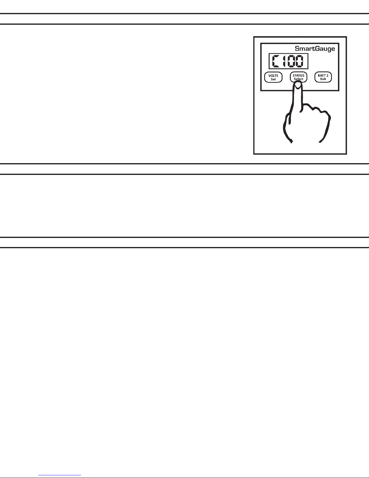
Once the Smartgauge™ has completed its initial start-up routine, you can determine the
charge status of the primary (house) battery bank by pressing the STATUS button. The
charge status will be displayed as a percentage. During the rst operation, the monitor
will display “C 75”, indicating 75 percent charge. As the Smartgauge™ goes through
its rst charge cycle, it will begin to “learn” the actual condition of the batteries, and it
will more accurate during subsequent periods of operation. If you know the actual level
of charge, you also have the option to manually set the charge status. See page 7 for
multiple methods for calibrating the monitor to ensure accuracy.
To revert to the Battery Voltage, press the VOLTS button. Pressing the BATT 2 button
will show the voltage on Battery 2 if the Smartgauge has been wired to both house and
starting batteries. The PGM/Batt 2 LED will be lit whenever voltage at the starting battery is being displayed.
To revert to the voltage or charge status of the house battery bank, press the VOLTS button or the STATUS
button.

PAGE 7
SECTION 3.2 – CALIBRATING BATTERY CHARGE STATUS
Initially Smartgauge™ defaults to an SoC of 75%. There are 4 very simple ways
this can be corrected:
1. If you know what the State of Charge is (for instance you may know the batteries
to be fully charged) you can enter the set-up menu and manually set the charge
status to what you know it to be. SoC can be manually set to any value between
0 and 100%. Enter the set-up menu as usual, then press the SET key until “Cxxx”
is displayed. Press and hold the SELECT button. The display will scroll from zero
to 100. When the desired value is displayed, press the VOLTS button. The display
will ash to show the value has been stored. The display will then move onto the
next menu item.
2. Charge or discharge the batteries to approach 75%. When the actual State of
Charge of the batteries and the displayed charge status meet, Smartgauge™ will
be in perfect synchronization with the batteries and will track the charge status
from that time onward.
3. Leave Smartgauge™ working for 48 hours. Use the battery system as usual,
Smartgauge will automatically catch up over the next 2-3 charge and discharge
cycles of the battery bank. Unlike all other battery state of charge meters currently
available, Smartgauge™ becomes more accurate the longer it is used. All other
battery state of charge meters become less accurate the longer they are used
and require multiple recalibrations.
4. The last method is to switch on a charging device and wait until you know the bat-
teries are fully charged (by the charger switching into oat charge mode). Then
manually set the SoC to 100%.
Important Note
On initial power-up, the Smartgauge™ performs a system check to determine
whether the system voltage is 12 volt or 24 volt. Smartgauge™ does this by taking eight voltage readings and averaging them. The Smartgauge™ decides whether this measured battery voltage indicates a 12- or 24-volt system. If,
at the time of this check, the battery voltage is outside the normal range, the Smartgauge™ may detect the wrong
system voltage. This is possible when Smartgauge™ is installed on a 24-volt system with extremely low battery voltage. The low voltage could result in the Smartgauge™ determining that the system is a 12-volt system. Alternately,
the Smartgauge™ could be connected to a 12-volt system with a faulty charger that’s applying high voltage to the
batteries. This would cause Smartgauge™ to incorrectly detect a 24-volt system.
If either of these happen, then Smartgauge™ simply will not operate. Once normal battery voltage is restored, the
Smartgauge™ will show a permanent HI or LO reading and an “E04” error. If this happens the solution is to reset the
monitor to factory default value, ensure the battery voltage is correct, and re-apply power.
SECTION 3.3 – POWER UP FOLLOWING POWER LOSS
The Smartgauge™ must always be connected to the batteries being monitored in order to operate. It cannot operate
and accurately track the State of Charge of the batteries if the sense wire is disconnected from the house battery bank.
Should sensing voltage be disrupted, it may be necessary to revert to one of the four methods described in Section
3.2.
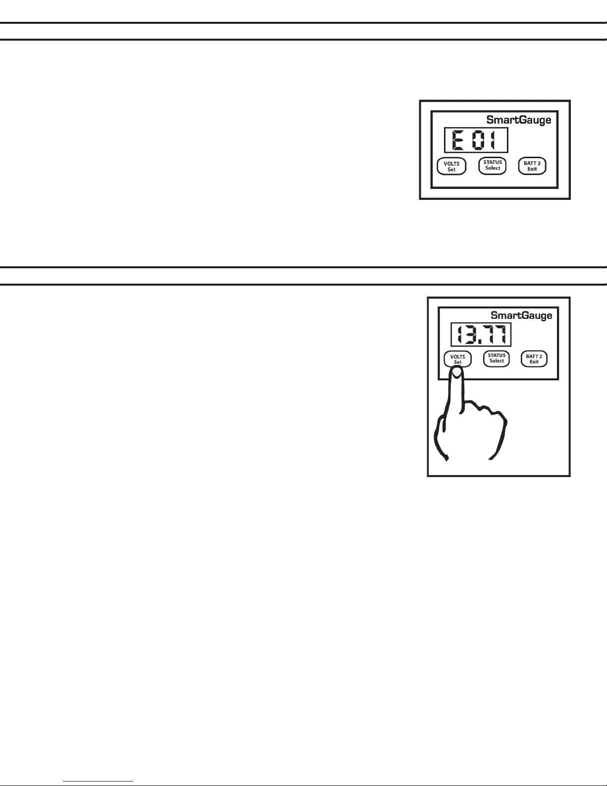
When a power failure occurs, the display will alternate between volts and “E01” (error 01 – lost power) until a key
is pressed. This is to alert the user to the fact that power has been lost. “E01” will continue to ash until a button is
pressed, if another error occurs the new error will not take over, “E01” will remain as the priority error. If the display
goes into sleep mode the error will always continue to ash. Again this is to alert the user to a problem.
The “E01” error alerts the user to the fact that power has been lost and therefore the charge status may no longer be
accurate. This is the sole reason for this error code. Once a button is pressed the display will move on to show a gure
– for example, 2.36 or 17.49 – This is the approximate time in hours and minutes since power was reapplied. It will
count up to a maximum of 99 hours and 59 minutes and will then remain at that display. This may help A) identify the
problem and B) make a better decision on whether the charge status will need to be reset or whether Smartgauge™
will have already re-synchronized itself.
SECTION 3.3 – POWER UP FOLLOWING POWER LOSS
PAGE 8
There is no need to reset any other functions. Smartgauge™ will remember all settings (with the exception that
status alarms will have been disabled). Refer to the ow chart headed “Re power up following power failure” for
details of the expected display at the back of the manual.
Note that re powering up Smartgauge™ results in a completely different
display from when it is rst powered up following rst installation (or following a
reset to factory defaults). In particular it does not carry out the System Check
(“SC”) and does not ask for the battery type. Both these parameters are stored
in non-volatile memory and will be retained from the previous use. Also note
that following re-application of power Smartgauge™ will continue to operate
as previously so, given time, it will successfully re-calibrate the charge status
of the batteries.
Note that previously set Status alarm will now be switched off. If for some reason it is required to revert the unit
to “as new” status, prior to rst installation (perhaps the unit is being moved to a new installation) then refer to
Section 6.0.
SECTION 4.0 – BASIC MONITOR USE
Pressing the VOLTS button will display house battery voltage. Pressing the
STATUS button will display charge status of the house battery bank. Pressing the
BATT 2 button will show the voltage on the engine starting battery and the PGM/
Batt 2 LED will light up to indicate that engine battery voltage is currently being
displayed. To return to house battery bank display, press VOLTS or STATUS.
If no buttons are activated for two minutes, the display will go into sleep mode.
This is a power saving feature. Smartgauge™ will continue to operate, calculating
the charge status and monitoring for error conditions, alarms etc. Pressing
any button will bring Smartgauge™ out of sleep mode and the display will
operate for an additional two minutes. Sleep mode may be defeated if required
(refer to “Display Modes” at the back of the manual).
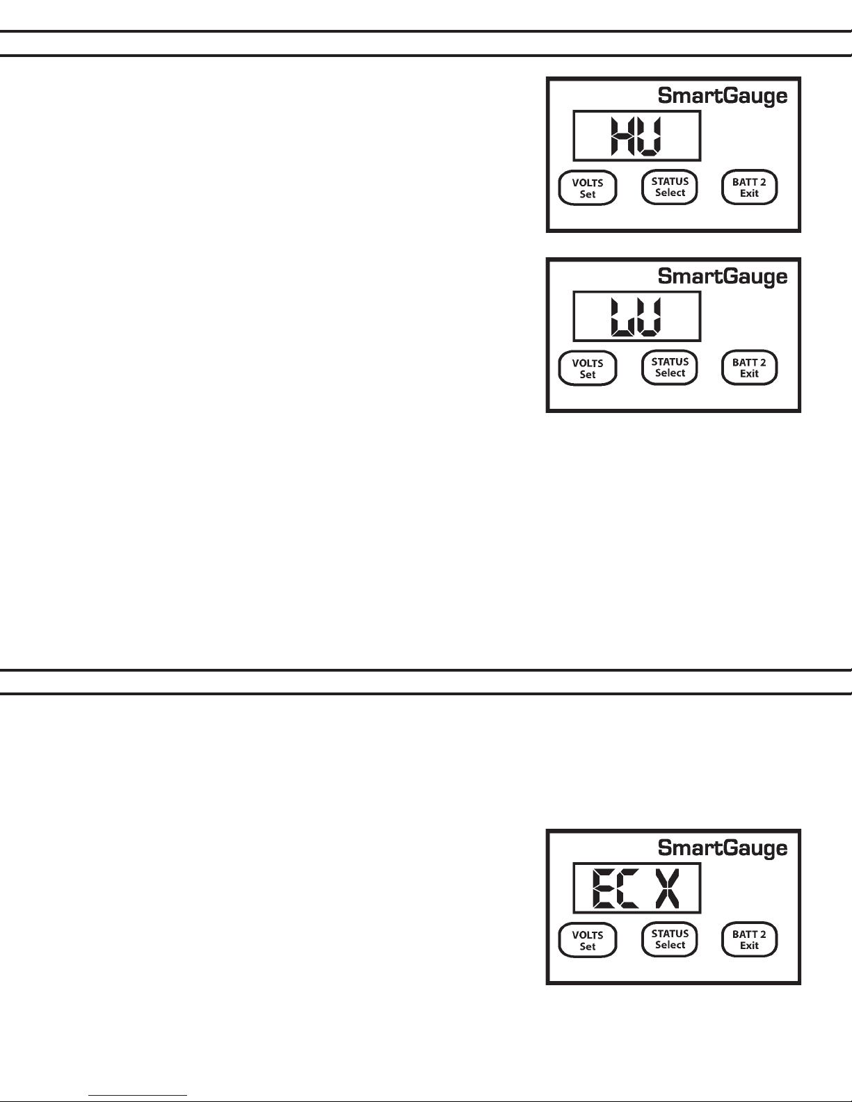
If the battery voltage goes outside the measurement range (>17 volts or <9 volts
for 12-volt systems) or (>34 volts or <18 for 24-volt systems), the volts display
will show “HI” or “LO” while the voltage remains outside of range. An “E04” error
will also be displayed and will remain displayed to alert the user to a problem – until a button is pressed. If the
battery voltage remains below the low-voltage warning for the set battery type an “E02” error will be displayed.
If the battery voltage remains above the high-voltage warning for the set battery type, an “E03” error will be
displayed.
The high and low voltage warnings described above are outside the preset limits which vary for each battery
type. “HI” or “LO” voltage displays should be responded to promptly, as battery damage or other dangerous
con- ditions may be responsible for the alerts. If power is lost an “E01” error will be displayed.
“HI” and “LO” error displays are only shown if the display is currently set to “Volts”. They are not displayed
if the display is set to “Status”. They are also not shown if the display has gone into sleep mode. But the
resulting error message will remain displayed. All error codes are displayed regardless of monitor mode.
They are shown even if the display has gone into sleep mode.

PAGE 9
The Smartgauge™ set-up menu allows the user to set and adjust a variety of the
monitor’s features:
To enter the set-up menu press both the VOLTS and STATUS buttons simultaneously and
keep them pressed. After 2 seconds the display will change to “bt x” (battery type x).
When in the set-up menu, the PGM/Batt 2 LED will ash.
During set-up mode, all internal calculations stop. For this reason there is a time limit on
the set-up menu. Each item to be set will allow approximately two minutes for the user to
set the function. After two minutes elapse, the currently displayed selection will be written to
Smartgauge™ memory and the set-up menu will be exited. Smartgauge™ will then revert
to normal operation. When in the set-up menu, the main legends on the buttons are no longer active. Instead
the secondary legends are the appropriate functions. The secondary legends are in blue
smaller letters underneath the main legends.
Pressing the SELECT button will scroll the current displayed value or option to the
next available one. At the last value, Smartgauge™ will cycle to the rst value and
continue. Pressing the SELECT button will simply scroll round and round all available values
indenitely. Pressing the SET button will set the displayed value. When the value has been
selected, the display will ash 4 times to indicate the value has been written to memory. The
display will then move on to the next menu item.
Pressing the EXIT button does the same as pressing the SET button except that after
writing the value to memory, it exits the set-up menu instead of moving on to the next item.
SECTION 4.1 – SET UP MODE
At any time, when moving onto a new menu item, the existing value (be it alarm voltage set points, battery types,
display modes etc) will be displayed rst. Pressing the SET button will show each selected item without ever
changing any of them. This allows you to look through the menu to check all the settings without changing any
of them or having to remember what they should be set to.
SECTION 4.2 – SET UP MODE –
When entering the set-up menu, the programming mode is the battery type, shown as “bt x” where “bt” signies battery type and “x” shows the current selected type. If this is a rst power up, “x” will be 1. Otherwise it will
show whatever setting is the currently selected battery type. If you are unable to identify your battery technology,
please contact your battery supplier for advice.
The battery types are numbered 1 to 7 and are as follows:
• Type 1 Standard wet cell deep cycle Lead Acid - Use this setting for:-
1. Standard vented Lead Acid deep cycle
2. Lead acid recombinant (have a catalyzer in the cap to recombine the oxygen and hydrogen back into
water that is normally lost during charging in a standard Lead Acid battery). Do not confuse with VRLA
(AGM or Gel).
• Type 2 Gel Cell – Use this setting only for Gel Cells
• Type 3 AGM - Absorbed Glass Matt (VRLA)
1. Use only for genuine AGM batteries. NOTE: There are two very distinct types of AGM batteries with very
different operational characteristics. In one type the only real difference is that the electrolyte is held in a
glass matt. This type usually have charge voltages very similar to ooded wet cell batteries. The off load
terminal voltages will also be very similar to ooded wet cell batteries. If your AGM batteries are of this
type then Smartgauge™ should be set to battery type 1.
BATTERY TYPE
2. The other type of AGM have additional chemicals in the battery and require lower charge voltages and
the off load terminal voltages will be similar to gel cells. This type require Smartgauge to be set to battery
type 3.
SECTION 4.2 – SET UP MODE –
BATTERY TYPE
PAGE 10
• Type 4 – HYBRID (Also known as Antimony/Calcium or Hi-Calcium.)
1. Usually identied by being sealed but the acid inside the battery is still liquid. Many are tted with a ‘magic
eye’ to give an approximate indication of battery condition. Usually marked maintenance free and its normally not possible to open the top of the battery.
• Type 5 – Carbon Fiber
1. Lead/Acid batteries with Carbon Fiber additives to the plates.
• Type 6 – Maintenance free, Calcium/Calcium.
1. Marketed as a semi-traction battery.
• Type 7 – Custom Program
2. Do not select type 7 unless your Smartgauge™ has been supplied with a specic battery program. Type
7 only appears on the set-up menu after the initial power up sequence.
SECTION 4.3 – SET UP MODE –
CHARGE STATUS
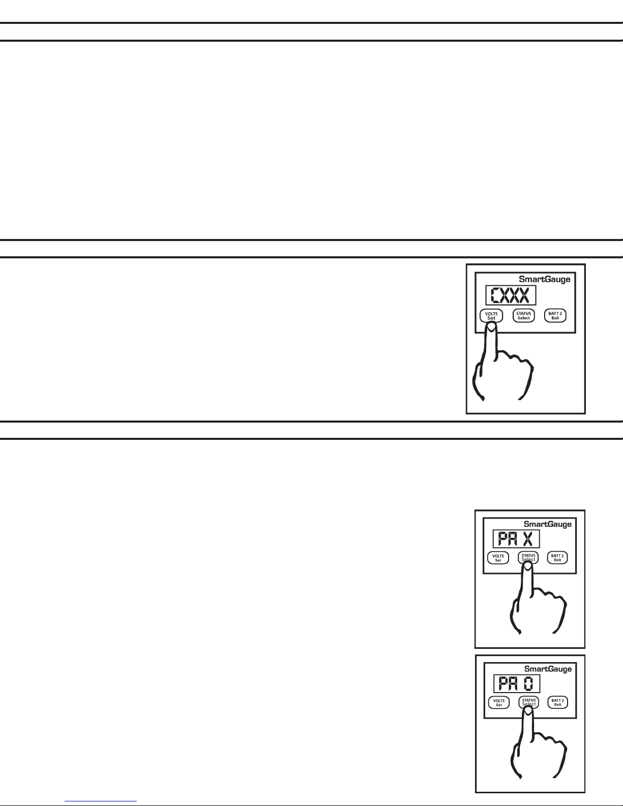
Charge status can be manually set to any value between 0 and 100%. Enter the set-up
menu as usual, then press the SET key until “Cxxx” is displayed. “C” signies charge
status. The xxx displayed will be the current calculated charge status. Pressing the
SELECT button will scroll up to and including 100 then cycle to zero and start again.
When the desired value is displayed, press the VOLTS key. The display will ash to
show the value has been stored. The display will then move onto the next menu item.
Alternatively, pressing the EXIT button will write the value to memory then exit the
set-up menu.
SECTION 4.4 – SET UP MODE –
There are two levels of alarm settings in Smartgauge™. The rst is the Primary Alarm which can be set OFF or can
be used to access low/high voltage or low SoC function. See Section 7.0 for information regarding alarm outputs.
Primary Alarm:
On entering this section of the set-up menu the display will show “PA x”. PA signifying Primary Alarm. “x” displaying
either “O” “ U” “ S”. or “t”. “O” means alarms are switched Off.
“U” means Uoltage (Voltage) alarm is enabled, “S” means low Status alarm is enabled. “t”
means a timed low status alarm is enabled. “S” and “t” type alarms are more fully described
under their respective headings. The SELECT button will scroll round them. The SET button
will set the desired alarm. The display will ash showing the value was written to memory.
Changing the alarm type will cancel any currently active alarms and reset the timed alarm
timers to the user’s programmed default value.
ALARM FUNCTIONS
On selecting “PA O” the display will ash and then move onto the next item in the set-up
menu, Secondary Alarm.
Individual Alarm Selection:
Set-up mode – Voltage Alarm:
1. On selecting “PA U” the display will ash to show the value was written to memory. The dis-
play will then show either “Hi” or “Lo”. The SELECT button will alternate between these two
options. “Hi” sets a high-voltage alarm. “Lo” sets a low-voltage alarm. Pressing SET will store
the value.
2. The display will then show “xx.xx” which is the lower voltage trip point. Once this is set (using
the SELECT and SET buttons) the display will again show “xx.xx” which is the upper voltage
trip point.

PAGE 11
If a low voltage alarm was set, the lower voltage trip point is the
voltage below which the actual battery voltage will have to fall in
order to trigger (activate) the alarm output. This is the activation
voltage. The factory default for this value is 11.80 volts. Pressing the SELECT button will scroll this value up to and including
16.50 volts. It will then cycle to 10.50 volts then continue to scroll
upwards. When the desired value is displayed, press the SET
button to write the value to memory, the display will ash. The
upper voltage trip point is the voltage which the actual battery
voltage will have to rise to in order to deactivate the alarm. This
is the deactivation voltage. The factory default for this is 13.20
volts. Pressing the Select button will scroll this value up to 16.50
volts, it will then wrap round to whatever value was previously entered for the alarm activation voltage. This
means that no matter what you do, Smartgauge™ will not allow this value to be set lower than the activation
voltage.
Pressing the SET button will write the value to memory. If a high voltage alarm
was set then the procedure remains identical except the upper voltage trip
point is the voltage which the battery voltage will have to rise to in order to acti-
vate the alarm. Once the alarm is triggered, the battery voltage will have to fall
back down below the lower voltage trip point in order to deactivate the alarm.
SECTION 4.4 – SET UP MODE –
ALARM FUNCTIONS
The display will then move on to the next item in the set-up menu, secondary
alarms. Remember, at any time in the set-up menu, pressing the EXIT button
will write the current value to memory then exit the set-up menu.
Clarication – For a low voltage alarm:
1. The battery voltage has to fall below the activation voltage to trigger the
alarm.
2. The battery voltage has to rise to the deactivation voltage to kill the alarm.
So if the activation voltage is set to 12.00 volts then the battery voltage will
have to fall to 11.99 volts to trigger the alarm. If the deactivation voltage is set
to 12.80 volts then the battery voltage will have to rise to 12.80 to cancel the alarm. Although the battery voltage
is displayed to a resolution of 0.05 volts (0.1 volts in 24 volt systems), internally it is measured and dealt with to
a ner resolution.
While 16.50 volts may seem very high for a maximum low voltage setting,
this does allow the low voltage alarm to be used for two extra functions. One
is as a “charger failure” alarm, the other is to enable the feature to be used to
auto-start a generator set feeding a constant current type battery charger and
shutting the generator down at the correct time.
For a high voltage alarm:-
1. The battery voltage has to rise to the deactivation voltage to trigger the
alarm.
2. The battery voltage has to fall below the activation voltage to kill the alarm.
Status Alarm
There are two types of Low-Status alarms. The rst is exactly the same as
the low-voltage alarm but operates on charge status instead of on battery
voltage. So the alarm will activate once the charge status falls below the chosen
activation status, and will deactivate after the charge status rises back up to the chosen deactivation status. This
type is designated in the display as “PA S”
The “PA S” type alarm is set in exactly the same way as the “PA U” alarm except “PA S” is selected instead of “PA
U”. i.e. the activation status will be set, followed by the deactivation status.
SECTION 4.4 – SET UP MODE –
Clarication:
1. The SoC% has to fall below the activation status to trigger the alarm.
2. The SoC% has to rise to the deactivation status to kill the alarm. The range limits are:
1. Activation status = 1 to 75%
2. Deactivation status = activation status to 100%
Factory defaults are activation status = 50%, deactivation status = 95%. These would be typical gures used for
an auto start gen-set (See Note 2 in addendum for additional information).
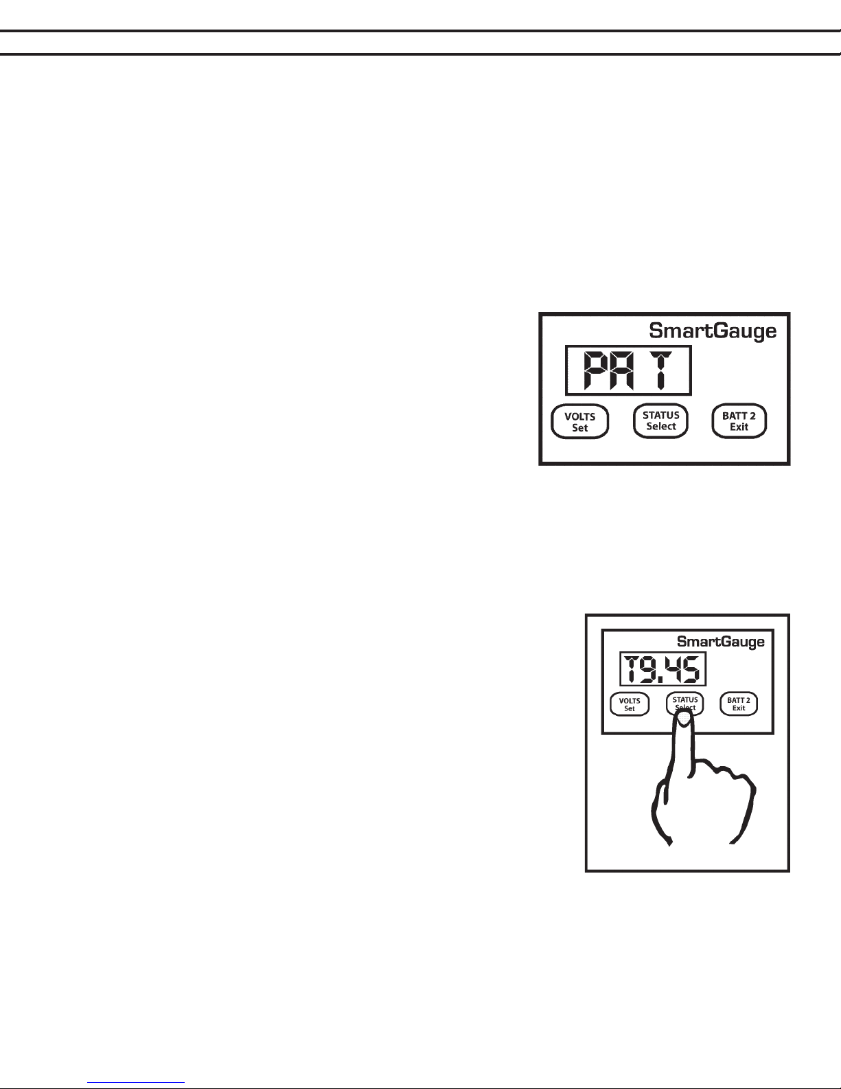
The “PA t” alarm is slightly different. If this alarm is set, the alarm will trigger (be activated) once the charge status falls below the activation status. The alarm will remain triggered until the status rises back up to the same
activation level but then, once this happens, a timer is started which counts down from the set time period, and
when it reaches zero, the alarm is deactivated. The main reason for this
type of alarm is to enable an auto start generator set to be started once
the charge status falls to a certain level and then run for a certain xed
period (see Note 2 in addendum).
On selecting “PA t” the display will ash to show the value was written
to memory. The display will then show “xx” which is the charge status
below which the actual battery charge status will have to fall in order to
trigger (activate) the alarm output. This is the activation status. The factory default for this value is 50%. Pressing the SELECT button will scroll
this value up to and including 75%. It will then cycle to 1 and continue to
scroll upwards. When the desired value is displayed, press the SET button to write the value to memory, the display will ash as usual. The activation status is now set. Note that this activation status shares the same memory
as that used for the normal low status alarm. So changing one, will change the other.
ALARM FUNCTIONS
PAGE 12
The display will now show “tx.xx”, indicating the time, in hours and minutes, that the alarm will remain activated.
The default is 4 hours. However, if an alarm of this type is actually active when you enter the set-up menu (i.e.
the alarm LED is on), then this gure will be the current time remaining, on the current countdown timer, rounded
to the nearest 15 minutes. This enables the user to increase or decrease the
remaining time for an existing alarm timer run.
Pressing the SELECT button will increase this time in steps of 15 minutes up
to a maximum of 9 hours and 45 minutes and cycle back to 15 minutes. Once
the desired time is reached, pressing the SET button will, as usual, cause the
display to ash, the value will be written to memory and the display will move
on to the next item in the set-up menu.
If an alarm is not active at the time you enter the set-up menu then this time
period will become the default time period for all future status timed alarms.
Remember, changing alarm type will cancel any currently active alarms. If this
menu item is entered while a timed alarm run is active and it shows the time remaining on the current run (as opposed to your default run time), only the time
remaining on the current run will be affected.
The normal full time for a timed alarm run will not be changed and will remain
as you last set it (or at the factory default if no changes have been made). It
is not possible to change the default run time whilst a timed alarm run is active. Note that this timed period is
approximate. The timed period and the display will be accurate to within about 10% Also note that internally
Smartgauge™ counts in seconds whereas the display only shows the minutes. It is rounded to the nearest minute so when the display counts down and reaches zero, there could in fact be 30 seconds remaining.
Set-up mode - Alarms – General
Once an alarm is triggered, the alarm output will activate. The Alarm LED on the front panel will illuminate and
the display will alternate between its current display (for 3 seconds) and the alarm display (for 1 second). The
PAGE 13
alarm display will either show “A LU” for Alarm Low Voltage, “A HU” for
Alarm High Voltage or “A LS” for Alarm Low Status. If “PA t” has been
set, then when the alarm triggers, the display will alternate in 2 ways. It
will show the current display (3 seconds), then it will show “A Lt” (Alarm
Low status timed),(1 second), it will then revert to the normal display (3
seconds), it will then show the time in hours and minutes until the alarm
is due to deactivate (for 1 second). For 9 hours 45 minutes, the display
would show “t9.45”. Note that when the display reaches 0.00 there could
actually be up to 30 seconds remaining. This is because the timer does
not display the seconds.
Changing the alarm type will cancel any currently active alarms. Alarm
set points and timers can be changed, and the existing alarm will remain
active. But actually changing the alarm type (such as from low voltage
to low status) will cancel the currently active alarm. This is a simple way
of cancelling an active alarm. If the display is in sleep mode then the
alarm output will still activate but the alarm status display will not show,
however the Alarm LED on the front panel will still light up. Pressing
either button will show what type of alarm has activated in case you
forget which type you set. And in the case of “PA t” will show the time
remaining before deactivation.
SECTION 4.4 – SET UP MODE –
ALARM FUNCTIONS
Indicates Alarm – High Voltage
Indicates Alarm – Low Voltage
Set-up mode - Secondary Alarm
The secondary alarm activates the alarm output, which can drive an external audible warning device or warning
light in an error code event. The display will show “SA x”, “SA” signifying Secondary Alarm, “x” showing the current setting. The default is “O”, Off. “x” can be set to any of the following:- O Off Default. Error codes will never
activate the alarm output.
U Voltage Error codes E 02 and E 03 (low- or high-voltage warnings for selected battery type) will activate the
alarm output. Note that if error codes are disabled (the next function in the set-up menu) this secondary alarm will
not operate. Range Error code “E04” (measurement range error) will activate the alarm output. Power lost Error
code “E01” (Power lost) will activate the alarm output. Note that if any error codes are disabled (the next function
in the set-up menu) then the disabled error codes will not activate this alarm.
SECTION 4.5 – SET UP MODE –
In some circumstances, it may be necessary to defeat the error code functions in Smartgauge™. Most
installations, particularly those where loads are used at the same time as charging, use what are known as 2 or
3 stage chargers. These chargers use a combination of an initial (the rst stage) “constant current” charge cycle
(usually referred to as the bulk stage) then switch to a second stage of constant voltage (usually referred to as
the acceptance or absorption cycle). Three stage chargers then switch to a third cycle known as “oat”. These
types of chargers usually keep to within very well accepted voltage limits during the charge cycle.
Certain constant voltage chargers may provide a very high charge
voltage of around 16 volts or more for a short period of time which can
trigger repetitive or continual E 03 error codes in Smartgauge™. For this
reason the next setting on the set-up menu allows error codes E 02 and
E 03 to be defeated. The display will show “EC x” signifying Error Codes
and “x” being either “1” for error codes enabled (the default) or “O” for
error codes disabled. Note that this setting only affects error codes E 02
and E 03. The other error codes will continue to operate. Note that error
code E 02 is a low voltage warning code. The reason this code is also
disabled is that users of the types of chargers that may trigger the E 03 error code are usually experienced users
who are aware of how far they can push batteries in order to get the maximum usage from them.
DEFEATING ERROR CODES

SECTION 4.5 – SET UP MODE –
If the “Secondary Alarm” function has been set to activate the alarm on E 02 or E 03, or set to activate the alarm
on all error codes, and E 02 and E 03 have been disabled then they will no longer trigger the alarm. The remaining error codes will still activate the alarm as programmed.
DEFEATING ERROR CODES
PAGE 14
SECTION 4.6 – SET UP MODE –
There are three display modes available in the Smartgauge™. The modes
apply whether the display is showing volts or charge status.
The default factory setting displays for 2 minutes before going into sleep
mode. This mode is signied in the set-up menu as “dt t” meaning display
type = timed. This display will remain active for 2 minutes following a button
press. It will then go back to sleep. Pressing a button will switch the display
back on for another 2 minutes.
The second display mode is “dt A” meaning “display type = Always” where the
display will always be on and will never go into sleep mode.
The third display mode is “dt U” meaning “display type = Voltage” where the
display will go into sleep mode, after 2 minutes, as usual, below a certain voltage but will always remain on above a certain voltage. This voltage is actually
the upper voltage trip point for the high/low voltage alarm. The factory default
setting for this is 13.20 volts (26.40 volts on 24 volt systems). So if this display mode (“dt U”) is selected and the alarm factory defaults have not been
adjusted, the display will blank as normal after 2 minutes if the battery voltage
is below this level but will always be on above this voltage. This makes sense
in so far as if the battery voltage is above this level then clearly the batteries
are either being charged or they are well charged and in either case the extra
few milliamps of power consumed is not an issue. It also allows a keen eye to
keep watch on the battery charge voltage without having to continually press
buttons. But when the charger is switched off Smartgauge™ will revert to the
minimum required current draw by blanking the display 2 minutes later.
DISPLAY BEHAVIOR
Note that whilst this setting uses the upper deactivation voltage level of the
low voltage alarm, the low voltage alarm does not have to be enabled or
ac- tive for this function to operate. The two functions merely share the same
value.
To select the display mode, enter the set-up menu as usual, then press the VOLTS button until “dt x” is displayed.
“dt” signifying display type, the x showing either t, A or U. Now press the STATUS button to scroll through the
three or four values. Press VOLTS to conrm the choice. The display will ash to show the value has been written
to memory. The display will then move onto the next menu item.
SECTION 4.7 – SET UP MODE –
The display brightness is fully adjustable to enable the Smartgauge™ to be used in any light conditions. One
of the advantages of this type of display (LED – Light Emitting Diode) as opposed to the other common display
(LCD – Liquid Crystal Display) is that they can be read in zero light conditions as well as daylight. To adjust the
display brightness enter the set-up menu, then press the VOLTS key until
“db x” is displayed. “db” signies display brightness, x indicates the current
brightness which will be from 1 to 8. The factory default value is 4.
Pressing the STATUS button will scroll through the values, cycling to 1 when
8 is reached. You will see the brightness change as you scroll through the
values. When you nd the brightness level that best suits your environment,
press the VOLTS button. The display will ash to show the value has been
stored then Smartgauge™ will move on to the nal item in the set-up menu.
DISPLAY BRIGHTNESS
PAGE 15
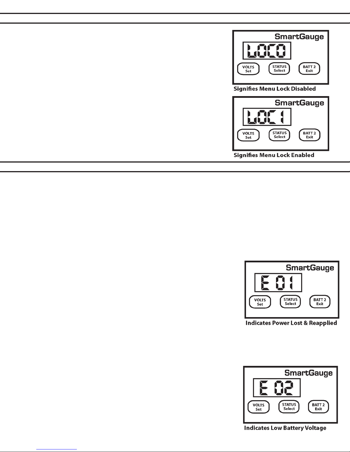
SECTION 4.8 – SET UP MODE –
MENU LOCK
The last item in the set-up menu will display Loc0. This allows access to
the set-up menu to be denied.
Pressing STATUS will alternate between Loc0 (meaning lock is disabled)
and Loc1 (meaning lock is enabled). Setting Loc0 will allow Smartgauge to
continue to operate exactly as before. Setting Loc1 will prevent future access to the set-up menu. All other functions of Smartgauge remain iden- tical. If Loc1 is set, then any future attempts to enter the set-up menu will be
completely ignored. In order to unlock Smartgauge™ it will be necessary
to attempt to perform a “reset to factory defaults”.
If the lock is disabled (Loc0), then “reset to factory defaults” will operate as
usual. If the lock is enabled (Loc1) then attempting to perform a “reset to
factory defaults” will not do so. It will simply unlock the unit to, once again,
allow access to the set-up menu.
SECTION 5.0 – ERROR CODES
Error codes do not indicate a problem with Smartgauge™. They indicate a problem with the installation or other
equipment such as chargers. For instance, a continual “E03” error signies a charger fault, not a Smartgauge™ fault.
With all “Exx” type error codes, the code is displayed alternately with the current display. If the display has gone into
sleep mode, the error code will still be displayed. This is to ensure that an error does not go unnoticed
The error code will continue to be displayed after the fault condition that caused the error has cleared. This means
that if, for instance, the charger is intermittently faulty, and occasionally charging at a much higher voltage than it
should be, this would force an error “E03” which would remain in the display even after the charger had gone back to
functioning correctly. In order to clear the error code simply press any button.
If another error occurs while an earlier error is displayed, the new error code will take precedence. The exception to
this is the unique case of an “E01” (lost power) error. This error takes precedence over all other errors.
“E01” – Power was lost and reapplied.
If power to the Smartgauge is lost, the Smartgauge™ has no way to to
determine the duration of power loss. Therefore, the “E01” may indicate that the
charge status may be incorrect and that any primary status alarms will have been
disabled. Alarm set points will still be as they were last set but the actual alarm will
be switched off and will remain so until re enabled by the user. Any low voltage
alarms or secondary alarms will remain set as they were prior to the power loss.
Pressing any button will clear the “E01” error code. The display will then show
the time in hours and minutes since power was reapplied (up to a maximum of
99 hours, 59 minutes). Pressing any button will clear this display. If no button is
pressed, the display will time out after 2 minutes then revert to normal
operation. While showing the time since re-power, the PGM LED will ash.
As with all errors, using the Secondary Alarm function described in the section regarding the set-up menu it is
possible to set the “E01” error to trigger the alarm output, perhaps to sound an audible alarm or light up a warning
light.
“E02” – Battery voltage has been below acceptable level for battery type.
Each battery type has certain voltage and time limits, which, if exceeded, may
damage the batteries.
For instance if a deep-cycle lead acid battery experiences a terminal voltage
lower than 10.2 volts for any appreciable length of time it may cause serious,
immediate, permanent damage to the battery. Smartgauge™ has different voltage
and time limits for each battery type. If this limit is exceeded then Smartgauge™
will generate an “E02” error. This error will alert the user to the problem. Be

SECTION 5.0 – ERROR CODES
aware that if this error code occurs it is an indication of a sever problem in the installation that, if allowed to persist,
will eventually destroy the batteries. Note that this error means the voltage and time limits have been outside of
range since a button was last pressed. It does not mean they are currently being exceeded. The error is stored
after the fault has cleared until the error is cleared by pressing a button.
PAGE 16
“E03” – Battery voltage has been above acceptable level for battery type.
This is similar to “E02” but for high voltage. The voltage level and time limits vary
dependent upon battery type. For example a wet cell antimony/antimony battery is far
more tolerant of high voltage levels than Gel cells and AGM types. Wet cell
calcium batteries are even more tolerant than antimony/antimony. Wet cell batteries
can tolerate 15 volts or more for long periods of time (always assuming the production
of explosive gasses is dealt with) whereas even 14.6 volts could severely damage Gel
cell or AGM batteries in a very short time.
This error means the voltage and time limits have been exceeded since the last error
was cleared. It does not mean they are currently being exceeded. The error is stored
after the fault has cleared until the error is cleared by pressing a button. Error codes
E 02 and E 03 can be disabled by the user. Refer to Section 4.5 for instructions.
“E04” – Battery voltage has been above acceptable level for battery type.
SmartGauge™ can accurately measure voltages between 9.00 and 17.00 volts in 12 volt mode and between 18.00
and 34.00 volts in 24 volt mode. If these limits are exceeded SmartGauge™ has no way of measuring the actual
voltage. Also, if these limits are exceeded there is something seriously wrong with the
installation. Such extreme voltages simply should not arise and indicates a serious
problem with the charging system.
HI Battery voltage is above upper measurement limit of 17.00 volts (34.00 volts in 24
volt installations).
LO Battery voltage is below lower measurement limit of 9.00 volts (18.00 volts in 24
volt installations). Note that Hi and LO errors will clear as soon as the voltage returns
to within the measurement range. They will, however, leave an “E04” error code on
the display. Repeated displays of the “E04” error code may indicate a system ground
error or a potential battery cell fault. The “E04” error indicates a condition which should
be addressed by a qualied electrician.
SECTION 6.0 – RESET TO FACTORY DEFAULT
Circumstances such as change of battery technology, or the need to override a
menu lock, require that you return the Smartgauge™ to its Factory Default state.
To return the monitor to its default settings:
1. Disconnect the power feed to Smartgauge™ (pull the fuses in each feed wire out).
2. Press both the VOLTS and STATUS buttons and keep them pressed.
3. Reapply power, still keeping the buttons pressed.
4. Smartgauge™ will display the software revision as usual. Keep the buttons pressed.
5. Smartgauge™ will display the battery model revision as usual. Keep the buttons
pressed.
6. The display will go blank.
7. Remove your ngers from the buttons.
8. Smartgauge™ will ash “Fr” (Factory reset).
9. Smartgauge™ will completely reset its internals to the factory defaults.
Smartgauge™ will now operate exactly like a new unit on rst power up
beginning by displaying the software revision. NOTE – If the set-up menu
lock had been set prior to this, then attempting to perform a “reset to factory
defaults” will not do so on the rst attempt. It will simply disable the menu
lock. A second attempt will perform the reset to factory defaults.

PAGE 17
1. The alarm output consists of 3 terminals labelled COM
(Common), NC (Normally Closed) and NO (Normally Open).
COM is connected internally via a relay to the NC terminal and
disconnected from the NO terminal. When an alarm is
activated the COM terminal is internally connected to the NO
terminal and disconnected from the NC terminal. At no time
are NC and NO terminals connected together (break before
make).
These three terminals are totally isolated from the rest of
Smartgauge ™ which means you can use them for more or less
anything within the following constraints:
1. The maximum voltage between any of the three terminals and/or the DC system to which Smartgauge™ is
connected is 48 volts. Exceeding this voltage may damage Smartgauge™, and will invalidate warranty.
2. The maximum permissible current to be carried by the alarm terminals is 500mA (0.5 amps). Exceeding this
current may damage Smartgauge and invalidates the warranty.
If either of these need to be exceeded then use the alarm output to operate an external relay with the required
specications.
SECTION 7.0 – ALARM OUTPUTS
SECTION 8.0 – ALARM NOTES
Assuming the low voltage alarm has been enabled it operates as follows:
1. Assume the low voltage activation setting is set to 12.00 volts and the deactivation setting is set to 13.20
volts. The battery voltage is at 12.6 volts. The alarm output is not active. COM is connected to NC. NO is not
connected to anything. The alarm LED is unlit.
2. As the battery voltage falls eventually it will reach 12.00 volts. The alarm output remains as above. When the
battery voltage falls to 11.99 volts (i.e. below the activation level) the alarm output will activate. COM is now
connected to NO. NC is not connected to anything. The alarm LED will light up. An audible alert connected
to the batteries via COM and NO will now beep.
3. As the voltage rises to say 12.80 volts the alarm output remains in this state. The battery voltage rises to
13.20 volts, the alarm output deactivates, COM is once again connected to NC and NO is connected to
nothing. The alarm LED will go off again. The sounder will go silent. Operation of the standard low status
alarm is identical to that of the low voltage alarm except, of course, that it operates on the charge status as
opposed to the battery voltage. Timed low status operates slightly differently. (See Section 9.0 Addendum.)
SECTION 9.0 – ADDENDUM
Charge Status during charging and discharging
During discharge, the Smartgauge™ accurately tracks the State of Charge of the batteries. When the opportunity
arises, the Smartgauge™ polls the battery voltage and uses the results of this measurement to compare with
its calculated gures for charge status. Smartgauge™ uses this information to adjust its battery model and the
Smartgauge™ algorithm so that future discharge cycles become more and more accurate. This is one of the
ways in which Smartgauge™ automatically adjusts itself to compensate for battery aging and the consequent
reduced battery capacity as they get older. This is also one of the ways in which Smartgauge™ is superior to a
meter based on the amp hours counting principle. This is a continual process that continues throughout the life
of the batteries so that Smartgauge™ always shows the percentage power remaining as a fraction of the actual
currently available battery capacity, as opposed to a percentage of what used to be available when the batteries
were new.
Discharging is the important phase, as this is when one really needs to know the State of Charge. During charging this is not possible due to the presence of the charger preventing Smartgauge™ ever getting an opportunity
to actually measure the charge status. In effect, if it tried, it would be attempting to measure the charge status
of the charger. During charging, Smartgauge™ only shows the calculated charge status as does an amp hours
counter. However Smartgauge™, because it operates on a different principle, calculates a charge status that is

PAGE 18
much more accurate. For this reason, it is possible that, during the charge cycle, the charge status displayed may
not be totally accurate. It will be within 10% of the actual battery charge status.
(Note that once discharging commences, Smartgauge™ will automatically re-synchronize itself within the rst
few minutes of discharge or within the rst 10 minutes of resting if no load is present. Smartgauge™ uses this
information to modify its battery models and algorithm to increase the accuracy of future calculations)
Smartgauge™ will provide a dependable indication (certainly better than an amp hours counter – and certainly
better than a volt meter but it could be that Smartgauge™ shows the charge status to have reached (as a worst
case example) 100% when in actual fact the batteries have only reached 90%.
Not charging to 100% charge state is one of the most common reasons for premature battery failure. Not charging to 100% (or occasionally well in excess of 100%) causes sulfation of the plates which is the main cause of
early battery failure. Therefore, as when using any form of charge status meter, and if using an intelligent charger, do not shut the charger down when Smartgauge™ indicates 100% SoC. Instead, rely upon the charger,
which can reach a much more accurate measurement of when the batteries are actually fully charged.
Also consider the possible results of using the Primary Alarm set to operate on charge status. If this is being
used to operate an auto start generator and charger, and the generator is regularly shut down before reaching
100% charge status this, again, will cause the plates to sulfate.
This is the reason for the option to set the low status alarm to operate for a xed period of time instead of
until reaching a certain charge status. In some installations it may be better to use this option to ensure that the
generator is run for a sufcient period of time. Either way, once discharging commences, Smartgauge™ will resynchronize itself (whatever the nal true charge status that was reached – i.e. it will not simply assume 100%
charge status, as many amp-hours counters do) and then give a true indication of the charge status throughout
the discharge cycle.
SECTION 9.0 – ADDENDUM
Conversely, it may be the case that the Smartgauge only reaches 90% charge status during the charge cycle
when in actual fact the batteries have reached 100% charge status and the intelligent charger has gone into
oat charge. If this happens, again Smartgauge™ will re-synchronize itself during the rst stage of the discharge
cycle.
Whatever happens, whenever Smartgauge™ “gets it wrong”, Smartgauge™ realizes, corrects itself, and uses
the information to modify its battery models and algorithm. An amp-hours counter simply “gets it wrong”, and
does nothing about it, and runs further and further adrift from the true State of Charge.
Smartgauge™ will NOT run out of synchronization with the batteries.
SECTION 10.0 - SPECIFICATIONS
PAGE 19
SECTION 11.0 – WARRANTY
Smartgauge™ is warranted to be free of workmanship defects for a period of 2 years. In the event of a warranty claim,
please contact Balmar Customer Service at +1-360-435-6100 for a return authorization.
Exclusions to this warranty include:
1. Opening the case.
2. Any form of external damage to the case such as drilled holes (excluding the 4 pre-drilled mounting holes) etc.
3. Use of the equipment in any manner not described in this owner’s manual.
4. Attempted modications.
5. Excess voltage or current as a result of incorrect installation.
6. Exceeding the rating of the alarm outputs.
7. Attempting to plug any non-approved equipment into the Smart interface state of chargeket or using the incorrect
type of communications lead.
8. Incorrect installation.
Visit www.balmar.net for more information regarding Balmar warranty policies and procedures.
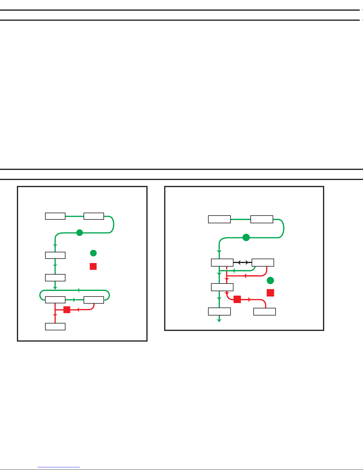
SECTION 12.0 – SMARTGAUGE FLOW CHARTS
12.1 – Display Mode
First Time Power Up/Following Factory Reset
Software
Revision
Checking
System
Voltage
System
Voltage
Selected
r 1.03
b 1.05
SC
SC 12
bt 1 bt 6
12.65
Normal
Display
Selections
STATUS BUTTO N
VOLTS BUTTO N
Battery Model
Revision
Battery
Type
Selections
Software
Revision
Alternatin g
Error/Voltage
Time Since
Re-Power
Hours/Minutes
Normal Display
Voltage
12.2 – Display Mode
Power Up Following Power Failure
r 1.03
12.65
XX.XX
12.65 C 75
b 1.05
E 01
STATUS BUTTO N
VOLTS BUTTO N
Battery Model
Revision
Normal Display
Charge Status
© Copyright 2016 Balmar LLC, Marysville, WA 98271 USA - Reproduction of this manual or any of its parts is
strictly forbidden without express written permission. For more information about this and other Balmar DC charging products,
bisit, www.balmar.net

SECTION 12.0 – SMARTGAUGE FLOW CHARTS
12.3 – Set Up Menu
PAGE 20
12.65
bt x
C X X
PA 0
LO
C 76
PA U
11.8
13.3
HI
PA S
C 50
C 95
NORMAL
OPERATIO N
VOLTS BUTTO N
STATUS BUTTO N
BATT 2 BUTTO N
PA T
C 50
T1.45
SA 0
EC 0 EC 1
dt t dt A dt U
db x
Loc 0
SA U SA r SA P SA A
Loc 1
12.65
NORMAL
OPERATIO N
 Loading...