

Page 1
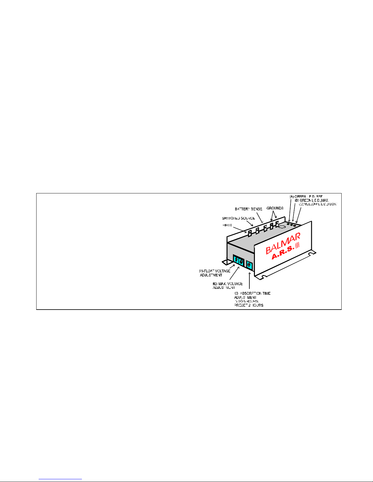
ARS III
This multi-stage, (3 step) regulator, is advantageous to users of larger banks of deep cycle lead acid or gel batteries which have been discharged to 50% and are being recharged to 85% capacity. This regulator also responds well when large D.C. loads are applied.
1. When the key switch is turned on, or after engine is started with oil pressure activated switches, the regulator
waits for about 1 min. before activating. This gives the engine a chance to develop oil pressure and warm up a
bit before the load of the alternator is applied. You will hear the ‘whine’ of the alternator and the engine ‘load up
a bit’” when the alternator comes on line. The A (green) L.E.D. will light when initial (float reference) voltage is
reached. This is factory set at 13.8 volts.
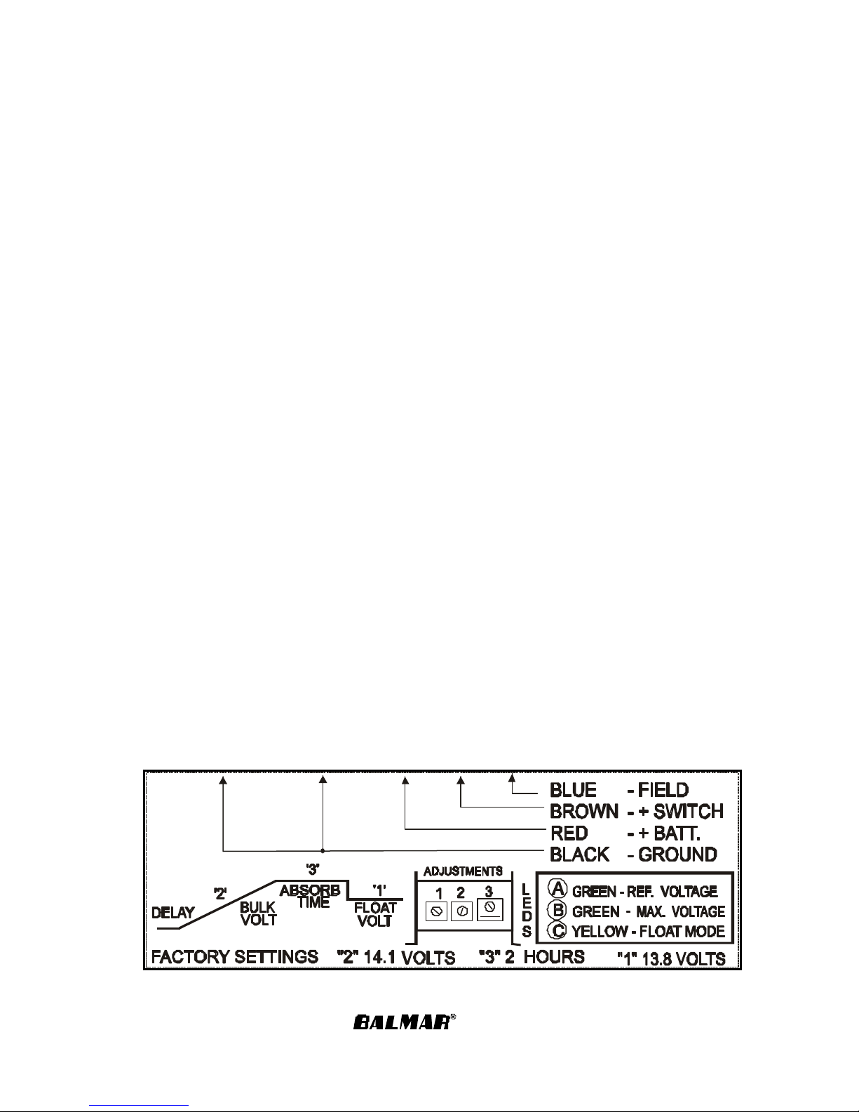
2. When the upper target voltage of 14.1 (factory setting for Gels) is sensed by the red wire, the B (green) L.E.
D. will light. Flickering is normal, the voltage will be held constant, and the batteries which may not have
reached max voltage will receive most of the current.
3. The absorption timer will start at this point, and if no large DC loads are
placed on the system that bring the sensing voltage below the upper target voltage, about two hours lat er the C
(yellow ) L.E.D. will come on, indicating the regulator has latched onto the ‘float’ voltage of 13.8V. This timer can
be adjusted from .5 to 5 hrs. The batteries must remain at the upper target voltage for the set timed period for
this to occur. Once in float mode, the voltage will be limited to 13.8V ‘float’ (or where you set it) until power to
the brown key switch is removed. Factory pre set is 2 hours.
4. ARS IlI ADJUSTMENTS: The regulator is factory
calibrated for Gel batteries . A lower float voltage may be recommended for flooded (non Gel) batteries. Consult your battery supplier for your correct maximum and float voltage setting. If you feel you should adjust the
output voltage, follow the procedure below.
Identify the correct pot. Float voltage is (#1) left pot, max (bulk) voltage is (#2) center pot, and absorption time
( .5 to 5 hrs.) is the (#3) right pot.
There is a dab of protective coating over the screwdriver slot. Remove this (it’s easy to scrape off with a small
knife) and using a small screwdriver, turn slowly clockwise to increase or counterclockwise to decrease voltage
or time. A small dab of TV Corna Dope or clear silicone can be applied when finished to provide protection
against moisture at the pot. Do not turn past stops.
a) Start engine, turning off all unnecessary electrical equipment.
b) Apply a digital voltmeter to the battery terminals.
c) Be sure the YELLOW light (C) on the ARS III is off.
d) Turn the center pot #2 clockwise to increase upper target voltage. Wait several minutes for the voltage to
rise and for the center GRE EN (B) light to turn on. This adjusts the absorption voltage and should be done with
batteries near a full charge.
When lit, the following circuits are operational:
Green - Lights when float setting is first
reached during ascent to upper
target (Bulk) voltage.
2nd Green - Indicates Bulk Voltage Achieved
Yellow - Indicates end of Absorption Time.
Indicates that regulator has settled
to 3rd stage Float Mode.
Dimensions: 4”L x 3.25”W x 1.5”H
Diagnostic LEDs
Page 2
e) Allow the engine to run until the YELLOW light (C) comes on. The batteries are now at the voltage level now
shown on the meter. To adjust the voltage down, you must apply enough load to bring the voltage of the battery
down to the pre set 13.8 V., then adjust.
f) Adjust the left #1 (float voltage) pot as necessary, using the meter. Your upper and lower voltages are now set .
Note: The float (lower) voltage can only be adjusted down if the batteries are in a slightly discharged state.
g) The right #3 timer increases time before entering float by clockwise rotation. Counter clockwise rotation decreases time.
Do not force the adjustment pots past their stops. This will void all warrantees on the regulator.
1. USING TH E L.E.D. FOR DIAGNOSTICS:
a. On the ARS III, if the YELLOW light (C) comes on first, you have a bad ground or the voltage to the
brown wire is receiving interference from a solenoid or similar device. The problem may be solved by adding a 12 volt relay to power up the brown wire from a “clean” 12 volt source, and have the ignition wire activate this relay.
NOTE the green LED’s are “voltage activated“ and will light when a shore side battery charger is providing
voltage at or above voltage set points.
2. TEST EQUIPMENT:
a. A good test quality volt meter (preferably digital)
b. In an emergency, a light bulb can verify power available or a working ground
c. A battery hydrometer with thermometer
d. An amp meter (not required but helpful)
3. GENERAL CHECK OUT PROCEDURE:
a. Remove and clean all charging system electrical connections (this Includes the ground side).
Also check the harness for resistance. The wires or terminals may become corroded and need to be
cleaned or replaced.
b. Charge all batteries to their proper full charge
state and determine if they are serviceable.
c. Check and tighten fan belts.
MOST CHARGING SYSTEM PROBLEMS will be corrected by performing the above checkout.
COMMON SYSTEM PROBLE MS:
* BAD GROUND SOMEWHERE IN SYSTEM
* Poor or dirty battery cable connections
* Improper wire size
* Loose fan belts
* Sulfated or worn out batteries
* Failed regulator or harness connections.
ARS III Side Label
27010 12 th Ave. NW, Stanwood WA. 98292
(360) 629-6100 FAX (360) 629-3210
2/98
 Loading...