


COBALT UHF-SERIES
Cobalt UHF Series Operator’s Manual
For Models: UHF-CNTL-232/485/IND –02 EU
UHF-CNTL-232/485/IND –02 US
Datalogic Automation reserves the right to make modifications and improvements to
its products and/or documentation without prior notification. Datalogic Automation
shall not be liable for technical or editorial errors or omissions contained herein, nor
for incidental or consequential damages resulting from the use of this material.
The text and graphic content of this publication may be used, printed and distributed
only when all of the following conditions are met:
Permission is first obtained from Datalogic Automation.
The content is used for non-commercial purposes only.
Copyright information is clearly displayed (Copyright © 2009, Datalogic Automation
S.r.l., All Rights Reserved).
The content is not modified.
The following are trademarks and/or registered trademarks of Datalogic Automation:
Escort Memory Systems®, and the Escort Memory Systems logo, Cobalt UHF™,
RFID AT WORK™, C-Macro™, C-MacroBuilder™, ABx™ and Cobalt Dashboard™.
COPYRIGHT © 2009 DATALOGIC AUTOMATION S.R.L., ALL RIGHTS RESERVED
28/05/2009
PAGE 2 OF 140

COBALT UHF-SERIES
COBALT UHF-SERIES
RFID CONTROLLERS
Ultra High Frequency, Multi Protocol, Passive Radio Frequency Identification Controllers
For Cobalt UHF-Series
RFID Controller Models:
UHF-CNTL-232-02
UHF-CNTL-485-02
UHF-CNTL-IND-02
OPERATOR’S MANUAL
How to Install, Configure and
Operate the Cobalt UHF-Series
RFID Controllers
PAGE 3 OF 140

COBALT UHF-SERIES REGULATORY COMPLIANCE
REGULATORY COMPLIANCE
FCC Compliance
Modifications or changes to this equipment without the expressed written approval of
Datalogic could void the authority to use the equipment.
This device complies with PART 15 of the FCC Rules. Operation is subject to the
following two conditions: (1) This device may not cause harmful interference, and (2)
this device must accept any interference received, including interference which may
cause undesired operation.
FCC ID: E36-UHF-CNTL-02
Radio Compliance
ENGLISH
Contact the competent authority responsible for the management of radio frequency
devices of your country to verify any possible restrictions or licenses required. Refer
to the web site:
http://europa.eu.int/comm/enterprise/rtte/spectr.htm
ITALIANO
Prendi contatto con l'autorità competente per la gestione degli apparati a radio
frequenza del tuo paese, per verificare eve nt uali rest ri zioni o licenze. Ulteriori
informazioni sono disponibili sul sito:
http://europa.eu.int/comm/enterprise/rtte/spectr.htm
FRANÇAIS
Contactez l'autorité compétente en la gestion des appareils à radio fréquence de
votre pays pour vérifier d'éventuelles restrictions ou licences. Pour tout
renseignement vous pouvez vous adresser au site web:
http://europa.eu.int/comm/enterprise/rtte/spectr.htm
DEUTSCH
Wenden Sie sich an die für Radiofrequenzgeräte zuständige Behörde Ihres Landes,
um zu prüfen ob es Einschränkungen gibt, oder eine Lizenz erforderlich ist. Weitere
Informationen finden Sie auf der Web Seite:
for further information.
.
.
http://europa.eu.int/comm/enterprise/rtte/spectr.htm
PAGE 4 OF 140
.
COBALT UHF-SERIES REGULATORY COMPLIANCE
ESPAÑOL
Contacta la autoridad com petente para la gestión de los dispositivos de radio
frecuencia de tu país, para verificar cualesquiera restricciones o licencias posibles
requerida. Además se puede encontrar mas información en el sitio Web:
http://europa.eu.int/comm/enterprise/rtte/spectr.htm
.
Power Supply
This product is intended to be installed by Qualified Personnel only.
This device is intended to be supplied by a UL Listed or CSA Certified Power Unit
with «Class 2» or LPS power source.
PAGE 5 OF 140

COBALT UHF-SERIES CONTENTS
CONTENTS
LIST OF TABLES ..................... ............... .............. ............... ................. .............. 10
LIST OF FIGURES... ................. ............... .............. ............... ............... ............... .11
CHAPTER 1: GETTING STARTED ............................................... 12
1.1 INTRODUCTI ON ........................... .............. ............... ............... ........... 12
1.1.1 About this Manual...........................................................................................12
1.2 COBALT CONTROLLER OVERVIEW ........................ ............... ............... .13
1.2.1 Cobalt Controller Features ..............................................................................13
1.2.2 UHF Operating Frequencies Options ...............................................................13
1.2.3 Connection and Communication Interface Options ...........................................14
1.2.4 Cobalt Controllers - Interface Connectors........................................................14
1.2.5 Package Contents ..........................................................................................14
1.3 COBALT CONTROLLER DIM ENSIONS .................................... ............... .15
1.3.1 UHF-CNTL-232/485/IND-02 Controller Dimensions ..........................................15
1.4 COBALT UHF RFID ANTENNAS ........... ............... ............... .............. ....1 7
1.4.1 Cobalt UHF RFID Antennas - Features ............................................................17
1.4.2 Cobalt UHF RFID Antennas - Models and Sizes...............................................17
1.4.3 UHF-ANT-2626-01-86 Antenna Dimensions ..................................................... 18
1.4.4 UHF-ANT-3030-01-91 Antenna Dimensions ..................................................... 19
1.4.5 Connecting the Antenna to the Controller ........................................................20
1.4.6 Optional Mounting Kit for Antenna Installation..................................................22
1.5 SUBNET16™ MULTI DROP PROTOCOL ................. ............... .............. ....2 3
CHAPTER 2: INSTALLING THE COBALT UHF ............................. 24
2.1 PREPARING FOR INST ALLATION ................ ............... ............... ............. 24
2.1.1 Power Requirements ......................................................................................24
2.1.2 Installation Guidelines ....................................................................................24
2.2 INSTALLING THE UHF -CNT L-23 2-0 2 ..... ............... ............... ............... .25
2.2.1 Steps to Install the UHF-CNTL-232-02.............................................................26
2.2.2 UHF-CNTL-232-02 Cabling Information ...........................................................27
2.3 INSTALLING THE UHF -CNT L-48 5-0 2 ..... ............... ............... ............... .29
2.3.1 Steps to Install the UHF-CNTL-485-02.............................................................30
2.3.2 UHF-CNTL-485-02 Cabling Information ...........................................................31
2.4 INSTALLING THE UHF -CNT L-IN D-0 2 ............ ............... ............... ........ 32
2.4.1 Steps to Install the UHF-CNTL-IND-02 ............................................................33
2.4.2 UHF-CNTL-IND-02 Cabling Information ...........................................................34
CHAPTER 3: CONFIGURING THE COBALT UHF .......................... 36
3.1 CONFIGURING THE COBALT VIA DASHBOARD UTILITY ...........................3 6
3.2 NOTE ABOUT THE READER POWER........... ............... ................. ........... 38
PAGE 6 OF 140

COBALT UHF-SERIES CONTENTS
3.3 CONFIGURING THE COB ALT VI A “CONFIGURATION TAG”....................... 38
3.3.1 Restoring Factory Defaults..............................................................................38
3.3.2 Manually Assigning Node ID (Cobalt -485 Model Only) ..................................... 39
3.3.3 Automatic Node ID Assignment via Gateway (Cobalt -485 Model Only) ............40
3.3.4 Automatic Node ID Assignment via Hub (Cobalt -485 Model Only) .................... 41
CHAPTER 4: LED STATUS .........................................................42
4.1 LED FUNCTIONS OVERVIEW ..................................... ............... ........... 42
4.1.1 LED Behavior for Cobalt UHF-CNTL-232-02 ....................................................42
4.1.2 LED Behavior for Cobalt UHF-CNTL-485-02 ....................................................43
4.1.3 LED Behavior for Cobalt UHF-CNTL-IND-02 ....................................................44
CHAPTER 5: COMMAND PROTOCOLS........................................45
5.1 COMMAND PROTOCOLS OVERVIEW. ............... ............... ................. ...... 45
5.2 RFID COMMAND TABLE .. ............... ................. ............... ............... ...... 46
5.2.1 RFID Commands - Note About the UHF-G2-525xx Tag M emory Structure .........48
5.3 ABX COMMAND PROTOCOL OVERVIEW................. ............... ............... .49
5.3.1 ABx Command Packet Structure......................................................................49
5.3.2 ABx Protocols - Headers and Terminators .......................................................49
5.3.3 ABx Response Packet Structure ......................................................................50
5.4 ABX FAST COMMAND PROTOCOL . .............. ............... ............... ........... 51
5.4.1 ABx Fast - Command / Response Procedure....................................................51
5.4.2 ABx Fast - Command Packet Structure............................................................52
5.4.3 ABx Fast – Command Packet Elements...........................................................53
5.4.4 ABx Fast - Multi-Tag Command Packet Structure .............................................56
5.4.5 ABx Fast - Multi-Tag Command Packet Elements.............................................57
5.4.6 ABx Fast - Response Packet Structure ............................................................ 58
5.4.7 ABx Fast Protocol: Error Response Packet Structure ......................................59
Single-Tag RFID Command 0xC2: R ea d EP C Co de ....................................................60
Single-Tag RFID Command 0xC3: W rite EP C Co de ....................................................61
Multi-Tag RFID Command 0xC4: R e ad E PC Co de ......................................................62
Controller Specific Command 0xC0: Set UHF Configuration.............................................64
Controller Specific Command 0xC1: Get UHF Configuration ............................................66
5.5 CBX COMMAND PROTOCOL ........................................... ............... ...... 67
5.5.1 CBx - Command Procedure.............................................................................67
5.5.2 CBx - Command Packet Structure ...................................................................68
5.5.3 CBx Response Packet Structure...................................................................... 69
5.5.4 CBx Multi-Tag Command Packet Structure ......................................................71
5.5.5 CBx Multi-Tag Command Packet Elements ......................................................72
5.5.6 CBx Multi-Tag Response Packet Structures .....................................................73
5.5.7 CBx Multi-Tag Respons e Final Terminati on Packet Structure ............................74
5.5.8 CBx Protocol: Error Response Packet Structure ...............................................75
CBx Single-Tag RFID Command 0xC2: R ead E PC Cod e .............................................76
CBx Single-Tag RFID Command 0xC3: W rit e EP C Co de .............................................78
Multi-Tag RFID Command 0xC4: R e ad E PC Co de ......................................................80
Controller Specific Command 0xC0: Set UHF Configuration.............................................82
Controller Specific Command 0xC1: Get UHF Configuration ............................................85
5.6 ERROR CODE TAB L E ...... ................. ............... ............... ............... ...... 87
PAGE 7 OF 140

COBALT UHF-SERIES CONTENTS
CHAPTER 6: ETHERNET/IP INTERFACE .....................................89
6.1 ETHERNET/IP CONFIGURATION OVERVIEW ....... ............... ................. ....8 9
6.2 HTML SERVER & ONDEMAND PLC SUPPORT ................................ ...... 90
6.3 HTML SERVER AND ONDEMAND UTILIT IES .......................................... 90
6.4 IP CONFIGURATION VIA HTML SERVER .................................... ........... 91
6.5 ONDEMAND CONFIGURATION FOR ETHERNET/IP ............ ............... ........ 93
6.6 CONFIGURING PLC CONTROLLER TAGS ... ............... ............... ............. 96
6.7 CHECKING ONDEMAND STATUS ..... ............... ................. ............... ...... 97
6.8 VERIFYING DAT A EXCHANGE WITH RSLOGIX 5000 ........................ ......9 8
6.8.1 Ethernet/IP Handshaking ................................................................................98
6.8.2 Ethernet/IP Handshaking Example ..................................................................99
6.9 ETHERNET/IP: OBJECT MODEL ....................... .................. .............. .. 10 0
6.9.1 Ethernet/IP Required Objects ........................................................................ 101
6.9.2 EtherNet/IP: Vendor Specific Objects ............................................................107
6.9.3 Application Object (0x67
CHAPTER 7: MODBUS TCP INTERFACE................................... 112
7.1 MODBUS TCP OVERVIEW ............................. ............... ............... ...... 1 12
7.2 MODBUS TCP CONFIGURATION VIA HTML SERVER ......... ................. .. 11 2
7.2.1 Setting the IP Address of the Cobalt .............................................................. 112
7.2.2 Modbus TCP - Command Packet Structure ....................................................115
7.2.3 Modbus TCP - Response Packet Structure .................................................... 116
7.2.4 Modbus TCP - Mapping for Node 33.............................................................. 116
7.3 MODBUS TCP - HANDSHAKING .................................................. ....... 1 18
7.3.1 Modbus TCP - Host/Cobalt Handshaking ....................................................... 119
7.3.2 Modbus TCP - Handshaking Example ............................................................119
10 Instances)........................................................ 110
–
CHAPTER 8: STANDARD TCP/IP INTERFACE ........................... 121
8.1 ST ANDARD TCP/IP OVERVIEW.. ............... ............... .............. ............121
8.2 ST ANDARD TCP/IP - IP CONFIGURATION VIA HTML SERVER ..............12 1
8.2.1 Setting the IP Address of the Cobalt .............................................................. 122
8.3 ST ANDARD TCP/IP - COMMAND & RESPONSE EXAMPLES ........ ...........124
8.3.1 Standard TCP/IP - Command Structure & Example ........................................ 125
8.3.2 Standard TCP/IP - Response Structure & Example.........................................126
CHAPTER 9: RFID OVERVIEW ................................................. 127
9.1 RFID OVERVIEW .......... .............. ............... ............... ............... .........127
9.2 OVERVIEW ON ULTR A HIGH FREQUENCY RFID APPLICATIONS ........... .. 12 8
9.2.1 UHF Standards and Regulations ................................................................... 128
9.2.2 UHF Signal Propagation ............................................................................... 130
9.2.3 Limiting Interference and UHF Signal Attenuation ..........................................132
APPENDIX A: TECHNICAL SPECIFICATIONS ............................. 133
COBALT UHF CONTROLLERS - TECHNI CAL SPECIFICATIONS ....... ............... .........133
PAGE 8 OF 140

COBALT UHF-SERIES CONTENTS
COBALT UHF ANTENNAS - TECHNICAL SPECIFICATIONS............................... ...... 1 35
APPENDIX B: MODELS & ACCESSORIES.................................. 136
COBALT UHF SERIES ACCESSORIES.... ............... ............... ............... .............. .. 136
COBALT UHF-SERIES RFID CONTROLLE RS........... ............... .................. ...........13 6
COBALT UHF-SERIES ANTENNAS .................. ............... ............... ............... ...... 1 37
SUBNET16 GATEW AY S............ ............... .............. ............... .................. ...........13 7
SUBNET16 HUBS........ .............. ............... ............... ............... ................. .........137
POWER SUPPLIES.. .............. .................. .............. ............... ............... ..............13 7
SOFTWARE APPLICATIONS ........ ............... ............... ............... ............... ...........138
COBALT CABLES & ACCESSORIES............... .............. ............... ............... .........138
WARRANTY .............................................................................. 140
PAGE 9 OF 140

COBALT UHF-SERIES LIST OF TABLES
LIST OF TABLES
Table 1-1: Connection and Communication Interface Options __________________________ 14
Table 1-2: Cobalt Controllers - Interface Connectors _________________________________ 14
Table 1-3: Package Contents ___________________________________________________ 14
Table 1-4: Cobalt UHF RFID Antennas - Models and Sizes ____________________________ 17
Table 1-5: Controller-Antenna Cabling Information___________________________________ 21
TTable 2-1: COM Port Parameter Defaults (UHF-CNTL-232-02) ________________________ 26
Table 2-2: RS232 Connector - Pinout _____________________________________________ 27
Table 2-3: RS485 Connector – Pinout ____________________________________________ 31
Table 2-4: Ethernet Connector - Pinout____________________________________________ 34
Table 2-5: Power Connector - Pinout _____________________________________________ 35
Table 3-1:Reader Radiated Power Limits __________________________________________ 38
Table 3-2: Configuration Tag – Restored Factory Defaults_____________________________ 39
Table 4-1: UHF-CNTL-232-02 - LEDs Description ___________________________________ 42
Table 4-2: UHF-CNTL-485-02 - LEDs Description ___________________________________ 43
Table 4-3: UHF-CNTL-IND-02 - LEDs Description ___________________________________ 44
Table 5-1: Command Protocol Matrix _____________________________________________ 45
Table 5-2: RFID Command Table ________________________________________________ 47
Table 5-3: UHF-G2-525xxx Tag Memory Structure___________________________________ 48
Table 5-4: ABx Protocols - Headers and Terminators_________________________________ 49
Table 5-5: ABx Fast - Command Packet Structure ___________________________________ 51
Table 5-6: ABx Fast - Command Packet Structure ___________________________________ 52
Table 5-7: ABx Fast - Command Size Parameter____________________________________ 53
Table 5-8: ABx Fast - Checksum Example _________________________________________ 55
Table 5-9: ABx Fast - Anti-Collision Command Packet Structure ________________________ 56
Table 5-10: ABx Fast - Response Packet Structure __________________________________ 58
Table 5-11: ABx Fast - Error Response Structure____________________________________ 59
Table 5-12: CBx Command Packet Structure _______________________________________ 68
Table 5-13: CBx Command Packet Structure _______________________________________ 69
Table 5-14: CBx Response Packet Structure _______________________________________ 70
Table 5-15: CBx Multi-Tag Command Packet Structure _______________________________ 72
Table 5-16: CBx Multi-Tag Response Packet Structure _______________________________ 73
Table 5-17: CBx Multi-Tag Response Final Termination Packet Structure _________________ 74
Table 5-18: CBx - Error Response Packet Structure__________________________________ 75
Table 5-19: Error Code Table___________________________________________________ 88
Table 6-1: Data Type Definitions________________________________________________ 101
Table 7-1: Modbus TCP - Command Packet Structure_______________________________ 115
Table 7-2: Modbus TCP - Response Packet Structure _______________________________ 116
Table 7-3: Modbus TCP - Mapping for Node 33 ____________________________________ 117
Table 8-1: Standard TCP/IP - Command Structure & Example ________________________ 125
Table 8-2: Standard TCP/IP - Response Structure & Example_________________________ 126
Table 9-1:Reader Radiated Power Limits Expressed in Watt or dBm ___________________ 129
Table Appendix B-1:Cobalt UHF Series Accessories ________________________________ 136
Table Appendix B-2: Cobalt Cables and Accessories________________________________ 139
PAGE 10 OF 140

COBALT UHF-SERIES LIST OF FIGURES
LIST OF FIGURES
Figure 1-1: Cobalt UHF Controller Dimensions – Top View ____________________________ 15
Figure 1-2: Cobalt UHF Controller Dimensions – Front View ___________________________ 16
Figure 1-3: Cobalt UHF Controller Dimensions – Right View ___________________________ 16
Figure 1-4: UHF-ANT-2626-01-86 Antenna Dimensions_______________________________ 18
Figure 1-5: UHF-ANT-3030-01-91 Antenna Dimensions_______________________________ 19
Figure 1-6: Connecting the Antenna to the Controller_________________________________ 20
Figure 1-7: TNC-Reverse Female Connector for Antenna Feeding ______________________ 21
Figure 1-8: UHF-CBL-0X - Controller-Antenna Coaxial Cable __________________________ 21
Figure 1-9:Optional Mounting Kit for Antennas ______________________________________ 22
Figure 1-10: Subnet16™ Industrial Gateway and Industrial Hub ________________________ 23
Figure 2-1: UHF-CNTL-232-02 Communication Interfaces_____________________________ 25
Figure 2-2: UHF-CNTL-232-02 Controller - RS232 Connector __________________________ 27
Figure 2-3: RS232 Serial Interface Cable – Schematic________________________________ 28
Figure 2-4: CBL-1493 Mountable Connector________________________________________ 28
Figure 2-5: UHF-CNTL-485-02 Communication Interfaces_____________________________ 29
Figure 2-6: UHF-CNTL-485-02 Controller - RS485 Connector __________________________ 31
Figure 2-7: UHF-CNTL-IND-02 Communication Interfaces_____________________________ 32
Figure 2-8: UHF-CNTL-IND-02 Controller - Ethernet & Power Connectors ________________ 34
Figure 6-1: The HTML Server - Main Page_________________________________________ 91
Figure 6-2: The IP Configuration Page ____________________________________________ 92
Figure 6-3: The OnDemand Configuration Page_____________________________________ 94
Figure 6-4: The OnDemand Status Page __________________________________________ 97
Figure 6-5: RSLogix 5000 ______________________________________________________ 98
Figure 7-1: The HTML Server - Main Page________________________________________ 113
Figure 7-2: The IP Configuration Page ___________________________________________ 114
Figure 8-1: The HTML Server - Main Page________________________________________ 122
Figure 8-2: The IP Configuration Page ___________________________________________ 123
Figure 8-3: Standard TCP/IP Protocol Command Packet Structure _____________________ 124
Figure 9-1: Radiowaves Spectrum Diagram _______________________________________ 128
Figure 9-2: Radiofrequency Bands Allocation______________________________________ 129
Figure 9-3: Circular Polarized Antenna’s Field Pattern _______________________________ 130
Figure 9-4: Circular Polarized Antenna’s Reading Range_____________________________ 131
PAGE 11 OF 140

COBALT UHF-SERIES CHAPTER 1: GETTING STARTED
CHAPTER 1:
GETTING STARTED
1.1 INTRODUCTION
Welcome to the Cobalt UHF-Series RFID Controllers - Operator’s Manual. This
manual will assist you in the
installation, configuration and
operation of the Cobalt UHF RFID
controllers.
The Cobalt UHF-Series is a complete
line of feature-rich, passive, ultra high
frequency, read/write Ra dioFrequency Identification devices that
provide RFID data collection and
control solutions to shop floor, itemlevel tracking and material handling
applications. Cobalt UHF controllers
are designed to be compact, rugged
and reliable, in order to meet and
exceed the requirements of the
industrial automation industry.
The Cobalt UHF is ideal for industrial
applications where single or multiple
tags must be read at long distance
and at high speed.
1.1.1 About this Manual
This manual provides guidelines and instructions for installing and oper ating the
Cobalt UHF-Series RFID Controllers. Included are descriptions of the RFID
command set and examples demo n strating how to issue commands to t he Co ba lt
RFID Controller.
Numbers expressed in Hexadecimal notation, are prefaced with “0x”. For example,
the number
user should refer to a chart containing Hex values and their corresponding decimal
integers.
in decimal is expressed as
ten
in hexadecimal. In case of need, the
0x0A
PAGE 12 OF 140
COBALT UHF-SERIES CHAPTER 1: GETTING STARTED
1.2 COBALT CONTROLLER OVERVIEW
1.2.1 Cobalt Controller Features
High performance, industrial RFID controller
Features long range, and high speed read/write rates
Supports RS232, RS485 or Ethernet interface connection
TM
RFID Air Protocol: EPCglobal
Compatible with UHF-G2-525 and UHF-G2-525HT RFID tags from Escort Memory
systems; compatible with all Class 1, Gen 2 RFID tags
Supports Escort Memory Systems’ ABx Fast™ and CBx™ RFID command protocols
Operates at the internationally recognized ISM frequencies of 865-870 MHz (ETSI
approved for European use) and of 902-928 MHz (FCC approved for North America
use)
Housed in rugged IP65 rated enclosure
LED status indicators display power status, COM ac t ivity and RF activ ity,
Software programmable, contains flash memory for firmware upgrades and internal
configuration storage
Long range antennas capable of reading EPCglobal Class 1 Gen2.
Class 1 Generation 2
1.2.2 UHF Operating Frequencies Options
The Cobalt UHF-Series Controllers are available in two different operating frequency
ranges:
865-870 MHz
902-928 MHz
Please refer to Appendix B - Models & Accessories for the corresponding Cobalt
UHF Controller models.
(ETSI approved for European use)
(FCC approved for North America use)
PAGE 13 OF 140
COBALT UHF-SERIES CHAPTER 1: GETTING STARTED
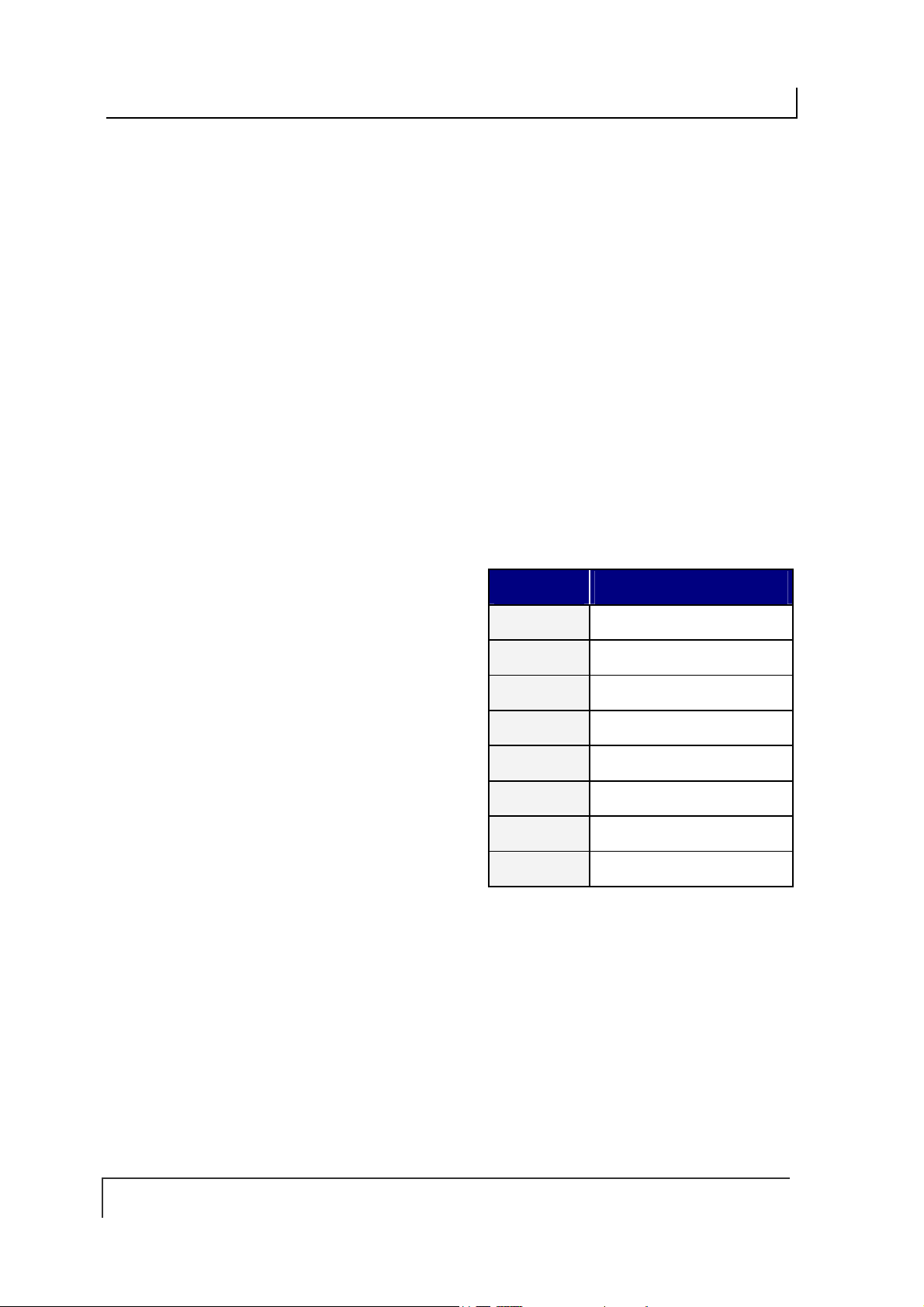
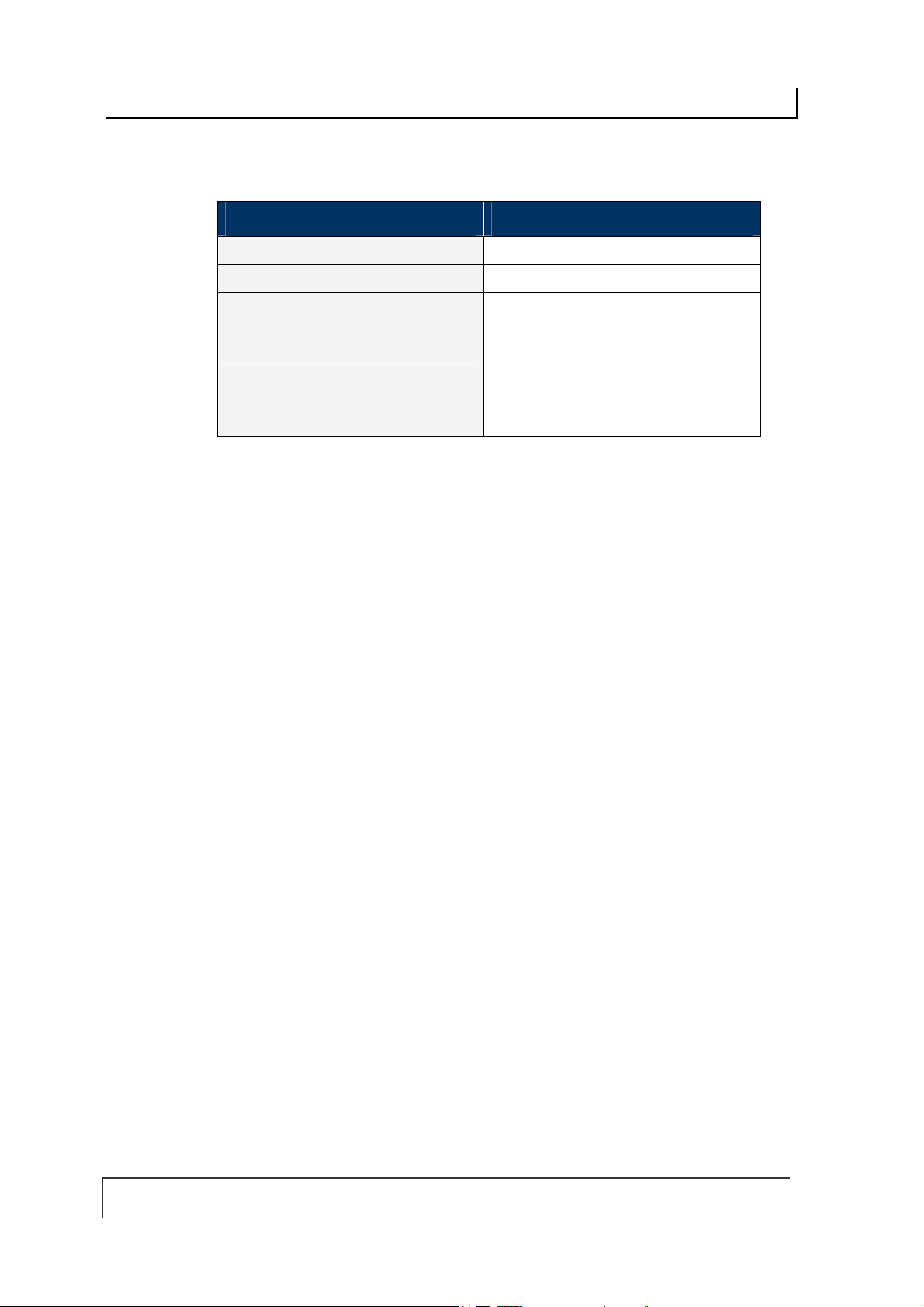
1.2.3 Connection and Communication Interface Options
There are three different models of the Cobalt HF-Series RFID Controllers. Each
model is designed to support a specific communication protocol and interface
connection option. The table below lists the three controller models, their respective
connection types and supported communication interfaces.
CONTROLLER
MODEL
UHF-CNTL-232-02
UHF-CNTL-485-02
UHF-CNTL-IND-02
INTERFACE
CONNECTION
RS232
RS485
Ethernet
Table 1-1: Connection and Communication Interface Options
COMMUNICATION
INTERFACE
Serial, Point-to-Point,
Host/Controller
Multidrop (Subnet16)
Bus Architecture
TCP/IP, Ethernet/IP,
Modbus TCP
MAX
CABLE
LENGTH
15m 115 KB
300m 115 KB
100m
1.2.4 Cobalt Controllers - Interface Connectors
CONTROLLER MODEL INTERFACE CONNECTOR(S)
UHF-CNTL-232-02
UHF-CNTL-485-02
UHF-CNTL-IND-02
(2 connectors)
8-pin, Male M12 Connector for Power and Data
5-pin, male M12 Connector for Power and Data
4-pin, Female M12, D-Code
Connector for Ethernet
5-pin, Male M12
Connector for Power
MAX
SPEED
100
Mb/s
Table 1-2: Cobalt Controllers - Interface Connectors
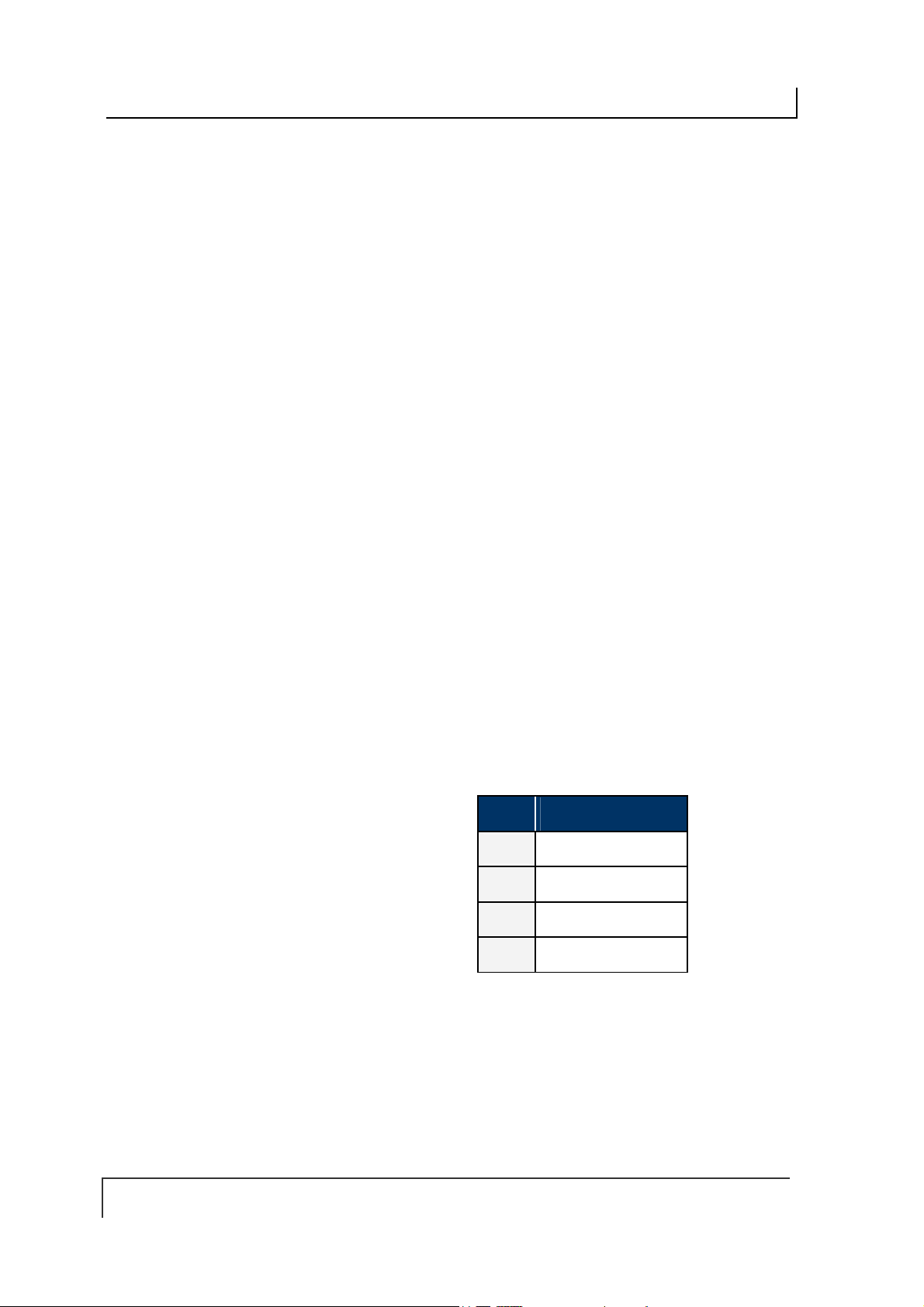
1.2.5 Package Contents
Unpack your Cobalt Controller hardware and accessories. Inspect each piece
carefully, if an item appears to be damaged, notify your EMS’ product distributor.
The Cobalt UHF Series RFID Controller product package contains the following
components:
DESCRIPTION QTY
Cobalt UHF-CNTL-xxx-02 RFID Controller 1
UHF-CNTL-xxx-02 Installation Guide 1
Cobalt UHF-Series Configuration Tag 1
Table 1-3: Package Contents
PAGE 14 OF 140

COBALT UHF-SERIES CHAPTER 1: GETTING STARTED
1.3 COBALT CONTROLLER DIMENSIONS
1.3.1 UHF-CNTL-232/485/IND-02 Controller Dimensions
Figure 1-1: Cobalt UHF Controller Dimensions – Top View
PAGE 15 OF 140

COBALT UHF-SERIES CHAPTER 1: GETTING STARTED
Figure 1-2: Cobalt UHF Controller Dimensions – Front View
Figure 1-3: Cobalt UHF Controller Dimensions – Right View
PAGE 16 OF 140
COBALT UHF-SERIES CHAPTER 1: GETTING STARTED
1.4 COBALT UHF RFID ANTENNAS
1.4.1 Cobalt UHF RFID Antennas - Features
Long read range (up to 3 meters with the UHF-G2-525HT tag and depending on
installation conditions)
Right-hand circular polarization ensures capturing tag data when tag is at random
orientations
3dB Beamwidth, 63° or 65°, providing a large reading zone
Housed in rugged IP67 rated enclosure
Mounting kit for easy installation available
1.4.2 Cobalt UHF RFID Antennas - Models and Sizes
The Cobalt UHF product family includes two RFID antenna models:
UHF-ANT-2626-01-86 for operating frequencies in the 865-870 MHz UHF ranges
UHF-ANT-3030-01-91 for operating frequencies in the 902-928 MHz UHF ranges
Please refer to the table below for antennas’ dimensions and part numbers:
ANTENNA MODEL
UHF-ANT-2626-01-86
UHF-ANT-3030-01-91
Table 1-4: Cobalt UHF RFID Antennas - Models and Sizes
ANTEN NA
P/N
970669001 868MHz 260 x 260mm (10.2 x 10.2 inch)
970665003 915MHz 305 x 305mm (12 x 12 inch)
UHF
FREQ
ANTEN NA SIZE
The two Cobalt UHF RFID Antennas are compatible with all Cobalt UHF-Series RFID
Controller models (see Appendix B - Models & Accessories
PAGE 17 OF 140
).
COBALT UHF-SERIES CHAPTER 1: GETTING STARTED
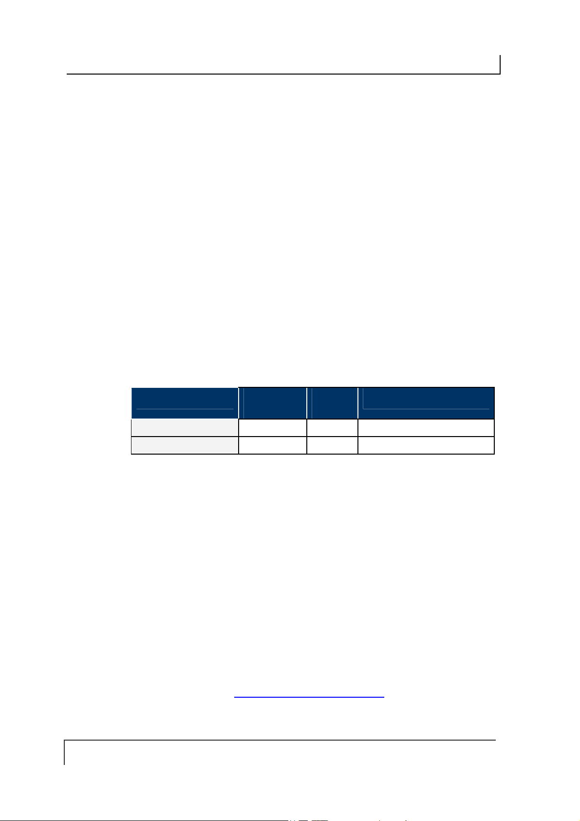
1.4.3 UHF-ANT-2626-01-86 Antenna Dimensions
Figure 1-4: UHF-ANT-2626-01-86 Antenna Dimensions
PAGE 18 OF 140
COBALT UHF-SERIES CHAPTER 1: GETTING STARTED
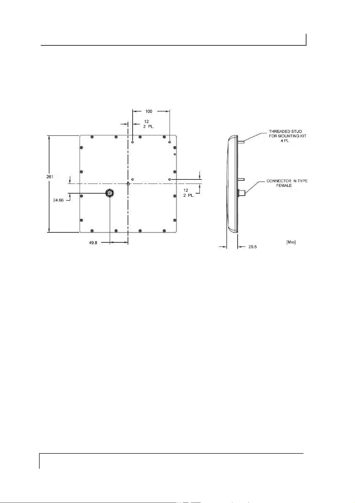
1.4.4 UHF-ANT-3030-01-91 Antenna Dimensions
Figure 1-5: UHF-ANT-3030-01-91 Antenna Dimensions
PAGE 19 OF 140

COBALT UHF-SERIES CHAPTER 1: GETTING STARTED
1.4.5 Connecting the Antenna to the Controller
The Cobalt UHF Antennas are connected to the top of the Cobalt UHF-Series RFID
Controller’s housing through a single coaxial cable.
Figure 1-6: Connecting the Antenna to the Controller
The Cobalt UHF antenna has one female, N-type connector located on its rear side.
The Cobalt UHF Controller has one TNC-Reverse female connector located on the
top of the Controller’s hous ing.
PAGE 20 OF 140
COBALT UHF-SERIES CHAPTER 1: GETTING STARTED
The RF port on the Cobalt UHF controller conn ec ts direc t ly t o the RF port on the
Cobalt UHF antenna via a compatible antenna feeder cable (see Table 1-6 below for
cabling information).
Figure 1-7: TNC-Reverse Female Connector for Antenna Feeding
For cabling part numbers and descriptions, please refer to the table below:
CABLE
MODEL
UHF-CBL-01 970106002
UHF-CBL-03 970106003
CABLING
P/N
Table 1-5: Controller-Antenna Cabling Information
DESCRIPTION
Coaxial Cable Controller-Antenna, TNC-Reverse Male to NType Male, 1 meter
Coaxial Cable Controller-Antenna, TNC-Reverse Male to NType Male, 3 meters
Figure 1-8: UHF-CBL-0X - Controller-Antenna Coaxial Cable
PAGE 21 OF 140

COBALT UHF-SERIES CHAPTER 1: GETTING STARTED
To connect the Cobalt UHF controller to the antenna, follow the steps below:
Attach the TNC-Reverse male plug of the controller-antenna coaxial cable to
the TNC- Reverse female connector located on the top of the controller’s
housing.
Attach the N-type male plug of the coaxial cable to the N-type female
connector located in the rear of the antenna’s body.
1.4.6 Optional Mounting Kit for Antenna Installation
Industrial environments where UHF RFID applications are used often entail specific
installation requirements.
The Cobalt UHF Antenna can take advantage of an optional mounting set, providing
an easy and solid installation (P/N: 970103035, Mounting Kit for large size UHF
Antennas).
Figure 1-9:Optional Mounting Kit for Antennas
PAGE 22 OF 140
COBALT UHF-SERIES CHAPTER 1: GETTING STARTED
1.5 SUBNET16™ MULTIDROP PROTOCOL
The UHF-CNTL-485-02 model includes support for Escort Memory Systems’
Subnet16™ Multidrop RFID networking protocol. Under the Subnet16 protocol, up to
16 UHF-CNTL-485-02 c ontrollers can be connected via a trunk and tap network to a
Subnet16 Industrial Gateway (GWY-01-IND-1), a Subnet16 TCP/IP Gateway (GWY-
01-TCP-01) or a Subnet16 Serial Gateway (GWY-01-232-1).
UHF-CNTL-485-02 models can also be connected direct ly to a Subnet16 Industrial
Hub (HUB-04-IND-01) or Subnet16 TCP/IP Hub (HUB-04-TCP-01). Subnet16 Hubs
possess four independent controller ports, four digital inputs and four digital outputs.
Figure 1-10: Subnet16™ Industrial Gateway and Industrial Hub
PAGE 23 OF 140
COBALT UHF-SERIES CHAPTER 2: INSTALLING THE COBALT UHF
CHAPTER 2:
INSTALLING THE COBALT UHF
2.1 PREPARING FOR INSTALLATION
The Cobalt UHF-Series RFID Controllers support point-to-point serial connections
(RS232 and RS485), multi-drop network connections (via Subnet16™ Gateway or
Hub) and Ethernet connections (TCP/IP, Ethernet/IP, Modbus TCP).
NOTE: Up to 16 UHF-CNTL-485-02 units can be networked via Subnet16 Gateway
interface module and Escort Memory Systems’ Subnet16 Multidrop Bus Architecture.
2.1.1 Power Requirements
The Cobalt UHF Controller requires an electrical supply voltage of 10~30VDC (see
Appendix A: Technical Specifications
Use a dedicated and regulated power supply connected to a suitable AC power
source that is capable of delivering these requirements. Do not apply power until the
entire system is wired and checked.
See Appendix B: Models & Accessories – Power Supplies
supplies.
).
for a list of available power
2.1.2 Installation Guidelines
Conduct a test phase where you will construct a small scale, independent
network that includes only the essential devices required to test your RFID
application. To avoid possible interference with other devices, do not initially
connect your RFID testing environment to an existing local area network.
RF performance and read/write range can be negatively impacted by the
proximity of metallic objects and liquids (for further information, refer to Section
9.2.2 “UHF Signal Propagation”). Avoid mounting the Cobalt antenna within
15cm (6 inches) of any metallic object or wet surface.
If electrical interference is encountered (as indicated by a reduction in read/write
performance), relocate the controller/antenna to an area free from potential
sources of interference.
Route cables away from other unshielded cables and away from wiring carrying
high voltage or high current. Avoid routing cables near motors and solenoids.
Always use adequate electro-static discharge (ESD) prevention measures to
dissipate potentially high voltages.
Refrain from mounting the controller/antenna near sources of EMI (electro-
magnetic interference) or near devices that gene ra te high ESD leve ls.
PAGE 24 OF 140
COBALT UHF-SERIES CHAPTER 2: INSTALLING THE COBALT UHF
2.2 INSTALLING THE UHF-CNTL-232-02
The UHF-CNTL-232-02 RFID Controller is designed for point-to-point RFID
applications, where the distance from host to controller is less than 15 meters (50
feet). The controller connects directly to a serial communications port on a host
computer via an RS232-compatible serial interface cable.
TO ANTENNA
TO RS232 HOST
CONNECTOR
Figure 2-1: UHF-CNTL-232-02 Communication Interfaces
PAGE 25 OF 140
COBALT UHF-SERIES CHAPTER 2: INSTALLING THE COBALT UHF
2.2.1 Steps to Install the UHF-CNTL-232-02
Select a suitable location for the Cobalt UHF Controller/Antenna.
1.
Attach the Cobalt UHF Antenna to the Cobalt UHF Controller, as described in
2.
Section 1.4.5 “Connecting the Antenna to the Controller”.
Fasten the combined controller and antenna to your mounting fixture using two
3.
M5 (#10)
washers and nuts. Tighten s crews to
Connect the 8-pin, female M12 connector from an RS232-compatible serial
4.
interface cable (
diameter screws (not included ) and secure them with appropriate
1.7 Nm or 15 lbs per inch ± 10%
EMS P/N: CBL-1478
) to the 8-pin, male M12 interface connector
on the Cobalt UHF-CNTL-232-02.
Connect the 9-pin, female D-sub connector on the serial interface cable to a
5.
COM port on a host computer. Tighten the cable’s two locking thumbscrews.
Connect the 2.5mm DC power plug on the power supply transformer to the DC
6.
power jack receptacle on the serial interface cable. Tighten the locking ring to
prevent power from becoming disconnected during use.
Plug the power supply transformer into a suitable AC power source. Apply power
7.
to the controller after all cable connections have been made. The green PWR
(power) LED will remain ON while the Cobalt is powered.
On the host computer, set COM port parameters to the following values:
8.
.
COM PORT PARAMETER DEFAULT VALUE
Baud Rate
Parity None
Data Bits 8
Stop Bits 1
Handshaking None
T
Table 2-1: COM Port Parameter Defaults (UHF-CNTL-232-02)
9600
*
*Supported baud rates include 9600, 19.2k, 38.4k, 57.6k, and 115.2k.
To verify operations, download the
9.
Memory Systems’ website (www.ems-rfid.com
Cobalt Dashboard Utility
). The Cobalt Dashboard Utility
allows users to configure their Cobalt UHF Controllers and send RFID
commands for testing purposes. Please refer to Section 3.1 “Configuring the
Cobalt via Dashboard Utility” for some generic Cobalt UHF configuration
examples.
from Escort
PAGE 26 OF 140
COBALT UHF-SERIES CHAPTER 2: INSTALLING THE COBALT UHF
2.2.2 UHF-CNTL-232-02 Cabling Information
The UHF-CNTL-232-02 has one 8-pin, male M12 RS232 connector located on the
bottom of the Controller’s housing.
Figure 2-2: UHF-CNTL-232-02 Controller - RS232 Connector
PIN # DESCRIPTION
1
2
3
4
10~30VDC POWER
0VDC (POWER GROUND)
NOT CONNECTED
NOT CONNECTED
5
NOT CONNECTED
6
7
8
RX
TX
SGND (SIGNAL GROUND)
Table 2-2: RS232 Connector - Pinout
UHF-CNTL-232-02
CBL-1478: Cable Assembly (8-pin, female M12 to RS232; with 2.5mm DC power
jack, 2m)
CBL-1488-XX: Cable (8-pin, female M12 to bare wire leads)
CABLING PART NUMBERS
CBL-1492-XX: Cable (8-pin, right-angle female M12 to bare wire leads)
CBL-1493: Connector (8-pos, straight female M12, field mountable)
(XX = Cable Length in Meters)
PAGE 27 OF 140

COBALT UHF-SERIES CHAPTER 2: INSTALLING THE COBALT UHF
RS232 SERIAL INTERFACE CABLE SCHEMATIC
If you intend to assemble your own RS232 serial interface cable, follow the schematic
below. Note that signals and electrical loads applied to Pin 6 (RX) and Pin 7 (TX)
should conform to RS232 specifications. For bulk RS232 cable, see Belden cable
P/N: 9941 (www.belden.com).
Figure 2-3: RS232 Serial Interface Cable – Schematic
CBL-1493: FIELD MOUNTABLE CONNECTOR
Figure 2-4: CBL-1493 Mountable Connector
The CBL-1493 field mountable connector is available for attaching the UHF-CNTL232-02 model to a host computer via bulk cable. See Appendix B: Cobalt Cables and
Accessories for more information regarding cables and connectors for the entire line
of Cobalt UHF RFID Controllers.
PAGE 28 OF 140
COBALT UHF-SERIES CHAPTER 2: INSTALLING THE COBALT UHF
2.3 INSTALLING THE UHF-CNTL-485-02
The UHF-CNTL-485-02 RFID Controller supports RS485 communications and Escort
Memory Systems’
Subnet16™
protocol.
Through the Subnet16 protocol, up to 16 UHF-CNTL-485-02 units can be connected
to one Subnet16 Gateway and four UHF-CNTL-485-02 units can be connected to
one Hub interface module. Subnet16 Gateways and Hubs assign each attached
controller a unique Node ID number through which communication with a host
computer and/or Programmable Logic Controller (PLC) is achieved.
For applications that require multiple UHF-CNTL-485-02 controllers, install and
configure each device one at a time.
multi-drop bus architecture and RFID network
TO ANTENNA
Figure 2-5: UHF-CNTL-485-02 Communication Interfaces
PAGE 29 OF 140
TO SUBNET16
NETWORK
COBALT UHF-SERIES CHAPTER 2: INSTALLING THE COBALT UHF
2.3.1 Steps to Install the UHF-CNTL-485-02
Select a suitable location for the Cobalt UHF Controller/Antenna.
1.
Attach the Cobalt UHF Antenna to the Cobalt UHF Controller, as described in
2.
Section 1.4.5 “Connecting the Antenna to the Controller”.
Fasten the combined controller and antenna to your mounting fixture using two
3.
M5 (#10) diameter screws (not included) and secure them with appropriate
washers and nuts. Tighten screw s to 1.7 Nm or 15 lbs per inc h ± 10%.
Connect the 5-pin, female end of an EMS approved Subnet16-compatible cable
4.
to the 5-pin, male M12 interface connector on the UHF-CNTL-485-02. Connect
the opposite end of this cable to a Subnet16 Gateway or Subnet16 Hub network
interface module. Connect the Gateway or Hub to your host computer via CAT5E
Ethernet cabling.*.
The UHF-CNTL-485-02 will require 10~30VDC (see Appendix A: Technical
5.
Specifications) from the network or interface module to which it is
connected.Utilize a regulated power supply for the controller that is capable of
delivering these requirements.
Turn the power supply ON. The green PWR (power) LED on the unit will
6.
illuminate when power is applied to the unit and remain ON while the Cobalt is
powered.
After installation is complete (see also Sections 3.3.2
7.
ID LEDs will display the currently assigned Subnet16 Node ID (in binary). Note:
the Cobalt’s default Node ID is Node 00; in which case none of the yellow Node
ID LEDs will be lit.
To verify operations, download the Cobalt Dashboard Utility from Escort Memory
8.
Systems’ website (www.ems-rfid.com). The Cobalt Dashboard Utility allows
users to configure their Cobalt UHF Controllers and send RFID commands for
testing purposes. Please refer to Section 3.1 “Configuring the Cobalt via
Dashboard Utility” for some generic Cobalt UHF configuration examples.
* For more information regarding the installation of a Subnet16 Gateway or
Subnet16 Hub, refer to the operator’s manual for each product, available online
at www.ems-rfid.com
.
and 3.3.3), the yellow Node
PAGE 30 OF 140

COBALT UHF-SERIES CHAPTER 2: INSTALLING THE COBALT UHF
2.3.2 UHF-CNTL-485-02 Cabling Information
The UHF-CNTL-485-02 has one
5-pin, male M12 RS485 connector
bottom of the Controller’s housing.
Figure 2-6: UHF-CNTL-485-02 Controller - RS485 Connector
PIN # DESCRIPTION
1
2
SIGNAL GND
10~30VDC PWR
located on the
Table 2-3: RS485 Connector – Pinout
3
4
5
0V (POWER GND)
Tx/Rx+
Tx/Rx-
UHF-CNTL-485-02 CABLING PART NUMBERS
CBL-1480-XX: Cable (5-pin, male M12 to 5-pin, female M12, ThinNet)
CBL-1481-XX: Cable (5-pin, male M12 to 5-pin, male M12, ThinNet)
(XX = Cable Length in Meters)
PAGE 31 OF 140
COBALT UHF-SERIES CHAPTER 2: INSTALLING THE COBALT UHF
2.4 INSTALLING THE UHF-CNTL-IND-02
The UHF-CNTL-IND-02 RFID Controller supports TCP/IP and Industrial Ethernet
communications. The UHF- C NT L -I N D- 02 can be co nn ec te d to a LA N or
Programmable Logic Controller (PLC) via CAT5E Ethernet cabling or it can be
connected directly to a host computer by means of a standard Ethernet crossover
cable.
TO ANTENNA
TO ETHERNET
NETWORK
Figure 2-7: UHF-CNTL-IND-02 Communication Interfaces
PAGE 32 OF 140
TO MAINS
COBALT UHF-SERIES CHAPTER 2: INSTALLING THE COBALT UHF
2.4.1 Steps to Install the UHF-CNTL-IND-02
Select a suitable location for the Cobalt UHF Controller/Antenna.
1.
Attach the Cobalt UHF Antenna to the Cobalt UHF Controller, as described in
2.
Section 1.4.5 “Connecting the Antenna to the Controller”.
Fasten the combined controller and antenna to your mounting fixture using two
3.
M5 (#10) diameter screws (not included) and secure them with appropriate
washers and nuts. Tighten screw s to 1.7 Nm or 15 lbs per inc h ± 10%.
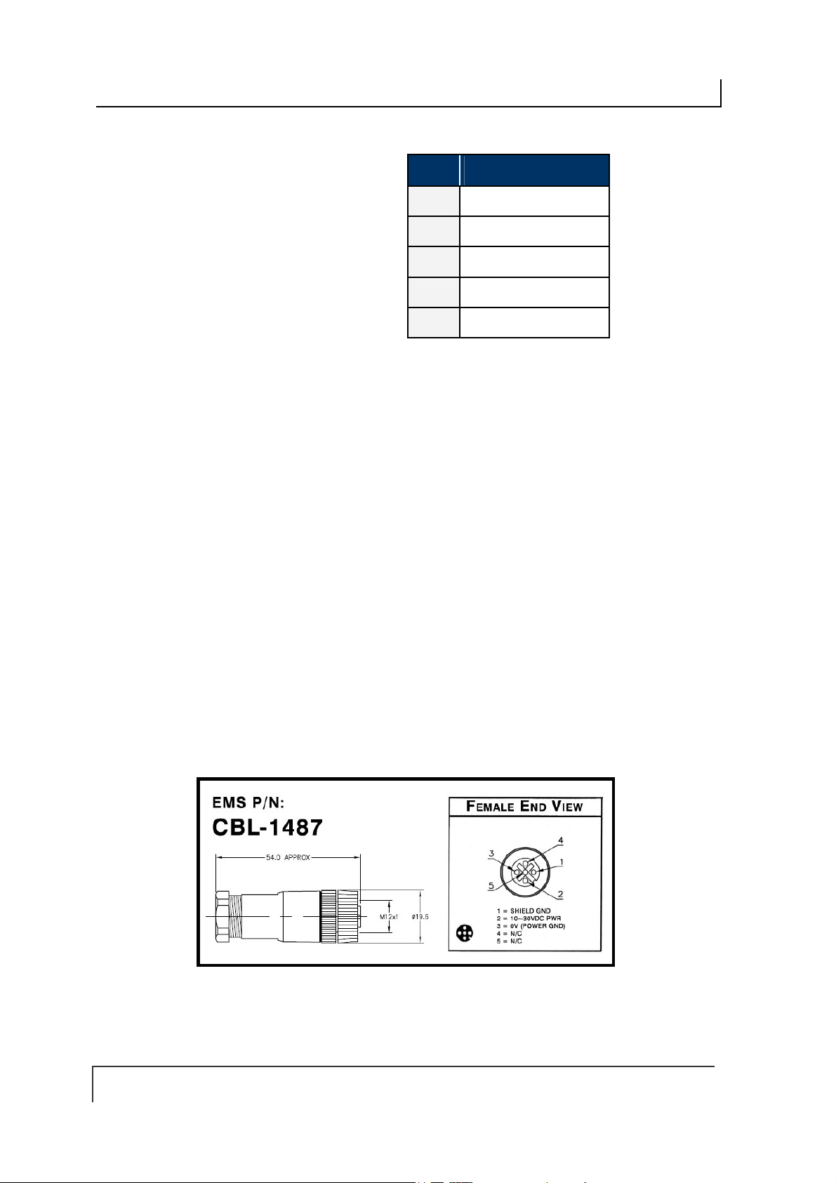
Connect the three wires from your power supply to pins 1-3 on the 5-pin, female,
4.
M12 connector (P/N: CBL-1487).
Attach the CBL-1487 connector to the 5-pin, male, M12 connector on the Cobalt
5.
Controller.
Attach the 4-pin, male, M12, D-Code connector from a CAT 5E (or better)
6.
industrial Ethernet cable (P/N: CBL-1515-05) to the 4-pin, female, M12, D-Code
connector on the Cobalt Controller.
Connect the other RJ45S end of the CBL-1515-05 cable to your application
7.
network or LAN. A crossover cable may be requi red if yo u are conn ect ing the
Cobalt directly to a host computer (rather than to a switch, hub or router).
Turn the power supply ON. The green Power LED on the unit will illuminate.
8.
After installation is complete, the amber Default IP LED will be lit when the
9.
controller is operating using its default IP address. The amber Actual IP LED will
be lit when the controller is operating with a user assigned IP address.
UHF-CNTL-IND-02 Default IP Address:
192.168.253.110
To verify operations, download the Cobalt Dashboard Utility from Escort Memory
10.
Systems’ website (www.ems-rfid.com). The Cobalt Dashboard Utility allows
users to configure their Cobalt UHF Controllers and send RFID commands for
testing purposes. Please refer to Section 3.1 “Configuring the Cobalt via
Dashboard Utility” for some generic Cobalt UHF configuration examples.
PAGE 33 OF 140
COBALT UHF-SERIES CHAPTER 2: INSTALLING THE COBALT UHF
2.4.2 UHF-CNTL-IND-02 Cabling Information
The UHF-CNTL-IND-02 includes:
a 4-pin, female M12, D-code connector for Ethernet communication
a 5-pin, male M12 connector for power.
These connectors are located on the bot to m of the Controller’s housing.
Figure 2-8: UHF-CNTL-IND-02 Controller - Ethernet & Power Connectors
Table 2-4: Ethernet Connector - Pinout
PIN # DESCRIPTION
1
2
3
4
TX+
RX+
TX-
RX-
PAGE 34 OF 140
COBALT UHF-SERIES CHAPTER 2: INSTALLING THE COBALT UHF
PIN # DESCRIPTION
1
2
3
NOT CONNECTED
10~30VDC POWER
0VDC (POWER GROUND)
4
5
NOT CONNECTED
NOT CONNECTED
Table 2-5: Power Connector - Pinout
UHF-CNTL-IND-02 CABLING PART NUMBERS
CBL-1515-05: Cable Assembly (CAT5E, RJ45S to 4-pin, male M12, D- Code, 5m)
CBL-1487: Field Mountable Connector (5-pos, female M12)
PAGE 35 OF 140

COBALT UHF-SERIES CHAPTER 3: CONFIGURING THE COBALT
CHAPTER 3:
CONFIGURING THE COBALT UHF
Stored in the Cobalt’s flash memory is a group of settings, attributes and parameters
known as the “Controller Configuration.” These parameters are related to the
communication protocol and operating mode.
The controller configuration can be modified by using Escort Memory Systems’
Cobalt Dashboard Utility (which can be downloaded from www.ems-rfid.com
through the use of a Cobalt UHF Configuration Tag (included with each Cobalt
Controller).
3.1 CONFIGURING THE COBALT VIA DASHBOARD UTILITY
The Cobalt Dashboard Utility is a software application that allows users to view,
modify, save and update the configuration settings of their Cobalt controllers.
) or
Download the Cobalt Dashboard from www.ems-rfid.com
included with the software to install and operate the utility and to set the controller’s
configuration.
The Cobalt Dashboard configuration utility is a general purpose software that can be
used with all the Cobalt family devices, including HF controllers and Gateways. To
use it with the UHF Series Controller you need to properly select the model at
startup. For example, in this case the Cobalt UHF Serial controller is selected:
and follow the instructions
Once the connection is established, you will see the normal startup screen of the
Dashboard utility. For more information on the Dashboard please see the manual that
you can find on the web site.
PAGE 36 OF 140

COBALT UHF-SERIES CHAPTER 3: CONFIGURING THE COBALT
OBALT UHF CONFIGURATION EXAMPLE: UHF CONFIGURATION TAB
C
One of the five different tabs shown in the Dashboard’s main display is the UHF
Configuration Tab.
This tab contains two different sections: EPC Read/Write and UHF Configuration
Section. These sections provide configuration details and contains parameter options
related to the UHF controller’s specific features.
In the EPC Read/Write section, for instance, users can read and write the EPC
portion of the UHF tags and also do an inventory of the ECP codes of all the tags in
the field of the reader. Setting the Repeat option will make the Dashboard
continuously sending the same command.
The UHF Configuration section allows users to set configuration parameters which
are specific to the UHF controller, namely:
UHF Power, representing the RF power in mW emitted during the
communication with tags
RF Channel, a 2-bytes value in the range 0-9 representing the RF channel to
use (this has a meaning only on the EU frequency reader)
PAGE 37 OF 140
COBALT UHF-SERIES CHAPTER 3: CONFIGURING THE COBALT
Choose Nearest, Instruct the reader to return only the information of the tag
with the stronger signal, which can be assumed is the “nearest” in space,
even if in real world condition this might be not always true.
Furthermore, users may retrieve or set the desired UHF configuration settings by
clicking on the buttons “Get UHF Config” and “Set UHF Config”.
3.2 NOTE ABOUT THE READER POWER
The performance of a UHF reader depends on the
reader output power that can be set with the above parameter. The radiated power
depends on the reader output power, the cable attenuation and the antenna gain.
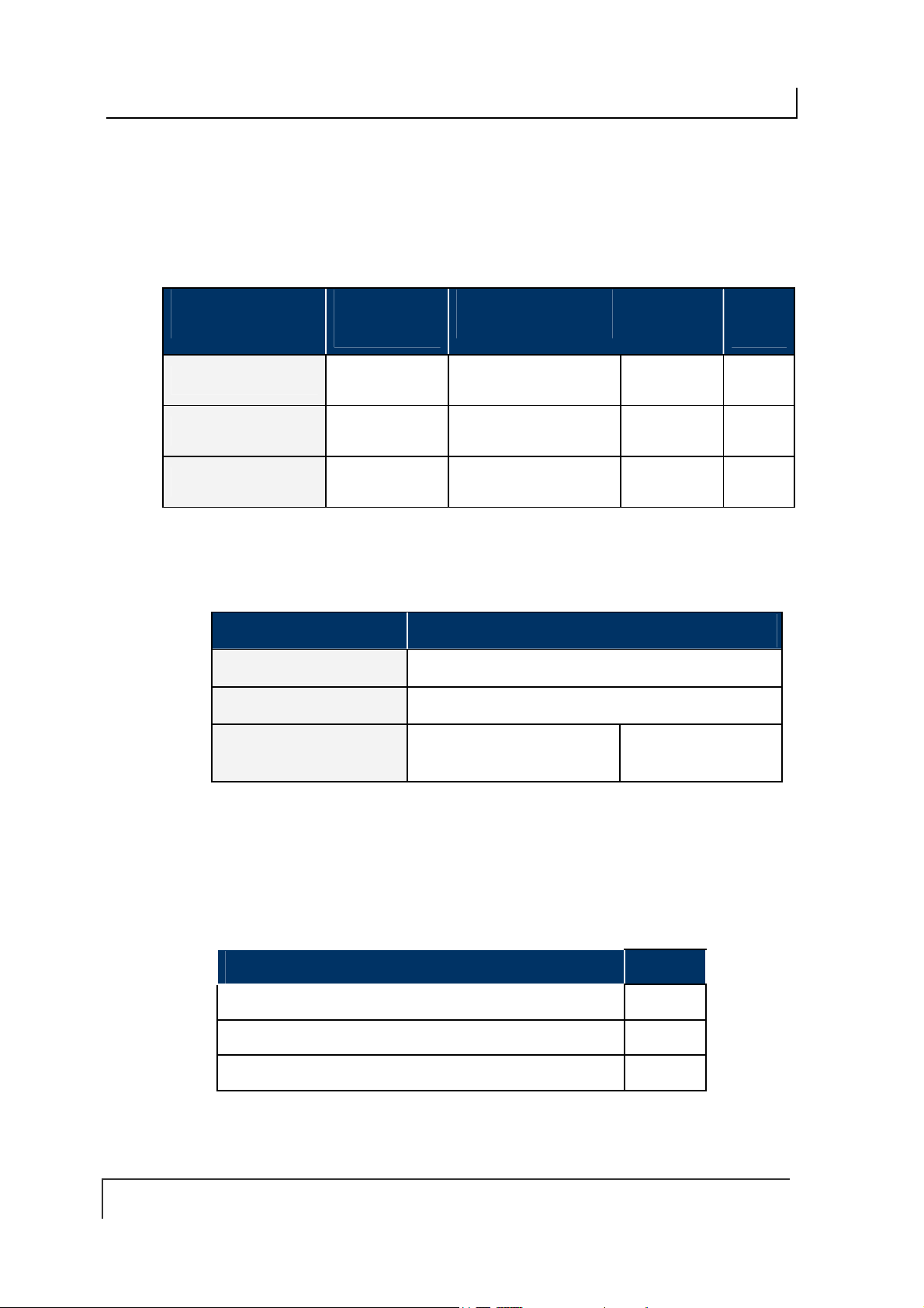
The radiated power limits are set by the different governments (see table below for
details).
REGION REGULATIONS RADIATED POWER
USA FCC Part 15
Europe EN 302 208
Table 3-1:Reader Radiated Power Limits
The UHF-CNTL-XXX-02 controllers produce up to 500 mW output power.
4 W EIRP (36 dBm)
2 W ERP (35 dBm)
radiated
power, not simply on the
EXAMPLE OF A CALCULATION:
Radiated Power = Reader Power + Antenna Gain – Cable Losses
500 mW (27dBm) + 6.85 dBi - 1.5dBm = 32.35 dBm (~1.7 W ERP)
3.3 CONFIGURING THE COBALT VIA “CONFIGURATION
TAG”
As noted, the Cobalt UHF controllers are software configurable via the Cobalt
Dashboard Utility. However, they can also be configured through the use of the
Cobalt UHF Configuration Tag supplied with each unit.
The Configuration Tag can be used to restore the factory default values for all
versions of the Cobalt UHF RFID Controller.
3.3.1 Restoring Factory Defaults
Place the Configuration Tag in the antenna’s RF field.
1.
Cycle power to the controller or issue the “Reset Controller” command
2.
(Command 0x35).
As power returns to the unit, the LEDs will blink.
After the LEDs blink, remove the Configuration Tag from the antenna’s RF field.
3.
Factory default values have been restored.
PAGE 38 OF 140
COBALT UHF-SERIES CHAPTER 3: CONFIGURING THE COBALT
The following factory default values will be restored on the controller:
CONFIGURATION PARAMETER FACTORY DEFAULT VALUE
Continuous Read Mode
Macros and Triggers
UHF Power
RF channel
Choose Nearest
RS232 - Serial Communications
RS485 - Node ID
IND – TCP/IP Address
Table 3-2: Configuration Tag – Restored Factory Defaults
Disabled
Erased
500 mW
0
Disabled
9600, N, 8, 1, N
0
192.168.253.110
3.3.2 Manually Assigning Node ID (Cobalt -485 Model
Only)
On the UHF-CNTL-485-02, the five amber Node LEDs display (in binary notation) the
numerical Node ID value of the controller. For example, if Node LEDs 1, 2 and 8 are
ON, the controller has been assigned Node ID 11.
Follow the steps below to assign a Node ID value manually to an UHF-CNTL-485-02.
Place the Configuration Tag in the antenna’s RF field.
1.
Cycle power to the controller or issue the “Reset Controller” command
2.
(Command 0x35 for ABx Fast, Command 0x54 for CBx).
As power returns to the unit, the LEDs will blink.
Remove the Configuration Tag from the antenna’s RF field and then immediately
3.
place it back within antenna range. Verify that all five amber Node LEDs are OFF
(indicating that the controller’s Node ID was reset to zero).
With all amber Node LEDs OFF, remove the Configuration Tag from the
4.
antenna’s RF field and then immediately place it back in the antenna’s RF field to
increment the Node ID value by one (from Node ID 00 to 01, in this case). The
lone amber Node 1 LED will illuminate to indicate that Node 01 is selected.
You may repeat Step 4 until the desired Node ID number is reached. The value
5.
is incremented by one each time a Configuration Tag is withdrawn from and reintroduced to the Cobalt HF Antenna’s RF field. This procedure can be used to
cycle through all 16 possible Node ID values. Note that after reaching Node ID
16, incrementing the value once more returns the selected Node ID number to
zero.
After setting the desired Node ID, remove the Configuration Tag from the RF field
6.
and allow approximately 10 seconds for the unit to reset and resume operation
under its new Node ID value.
PAGE 39 OF 140
COBALT UHF-SERIES CHAPTER 3: CONFIGURING THE COBALT
3.3.3 Automatic Node ID Assignment via Gateway
(Cobalt -485 Model Only)
For multi-drop network configurations (where up to 16 Cobalt UHF-CNTL-485-02
controllers are connected via one Subnet16 Gateway interface module), a Gateway
module can be instructed, through the use of a Configuration Tag, to automatically
assign each controller a separate Node ID number (between 1 and 16).
However, before the Gateway can be gin alloc atin g No de IDs autom at ic ally , each
UHF-CNTL-485-02 controller must first be restored to factory default values. In doing
so, the Cobalt’s Node ID number will be reset to zero.
Note that, by default, the Cobalt UHF-CNTL-485-02 controller ships pre-configured to
Node ID 00. Therefore, if your Cobalt is brand new, it should already be set to Node
ID 00. If it has previously been assigned another Node ID number, you will likely
need to reset its Node ID value to zero (see Section 3.2.1 – Restoring Factory
Defaults for instructions on resetting the controller’s Node ID to 00).
When automatically assigning a Node ID to a new Cobalt Controller, the Gateway will
normally issue the next available Node ID value.
The Gateway can also assign a new controller the same Node ID and configuration
settings of a previous Cobalt controller that has since disappeared from the network
or has been determined to be offline. Therefore, if a controller becomes damaged
and must be quickly replaced, a new Cobalt controller can be installed easily in its
place, allowing the Gateway to assign the new controller the same Node ID and
controller configuration settings as the recently replaced controller.
ATTENTION: Connect and configure only one RFID controller at a time. Conflicts can
occur when multiple controllers set to the same Node ID are simultaneously attached to
a multi-drop network. You may, however, leave connected any controller once it has
been has successfully assigned a Node ID by the Gateway.
Baud rates for all controllers must be set to 9600
Follow the steps below to assign the Cobalt -485 controller a Node ID automatically
via a Subnet16 Gateway.
Place a Configuration Tag within the Cobalt Antenna’s RF field.
1.
Cycle power to the controller or issue the “Reset Controller” command
2.
(Command 0x35 for ABx Fast, Command 0x54 for CBx).
As power returns to the unit, the LEDs will blink.
After the LEDs blink, remove the Configuration Tag from the antenna’s RF field
3.
and then immediately place it back within range. Confirm that all five amber Node
LEDs are OFF (indicating that the controller’s Node ID is set to zero) then
remove the tag from RF range.
Cycle power once again to the Cobalt (or issue the Reset Controller command).
4.
While the Cobalt is restarting, place the Configuration Tag back within the
antenna’s RF field. Allow 10 seconds for the Gateway to recognize and assign
the controller an available Node ID number, then remove the Configuration Tag
from RF range. Check the five amber Node LEDs to determine the assigned
Node ID.
PAGE 40 OF 140

COBALT UHF-SERIES CHAPTER 3: CONFIGURING THE COBALT
3.3.4 Automatic Node ID Assignment via Hub (Cobalt -485
Model Only)
Subnet16 Hub interface modules, which have four independent RFID controller ports,
can automatically assign an attache d UHF-CNTL-485-02 controller the corresponding
Node ID number of the port to which it is connected.
For example, if a controller is attached to port 1 on the Hub, it will be assigned Node
ID 01. If a controller that was previously assigned Node ID 03 is connected to port 2,
the Hub will override the controller’s internal configuration and automatically change it
from Node ID 03 to 02.
Follow the steps below to as sign the Node ID automatically to an RFID controller via
Subnet16 Hub:
Connect an UHF-CNTL-485-02 to controller port 1 on a Subnet16 Hub.
1.
Place the Configuration Tag within the antenna’s RF field and cycle power to
2.
the UHF-CNTL-485-02 controller.
When power returns to the unit, the LEDs on the controller will blink. Remove
3.
the Configuration Tag from RF range and then immediately place it back
within antenna range. Verify that all five amber Node LEDs are OFF
(indicating that the controller’s Node ID has been reset to zero). Then
remove the Configuration Tag from RF range and cycle power to the Hub
module.
While the Hub is restarting, place the Configuration Tag back into the
4.
antenna’s RF field. Allow several seconds for the Hub to recognize the
controller and assign it the corresponding Node ID number of the controller
port to which it is attached. The amber Node LEDs on the Cobalt will display
its assigned Node ID (between one and four) in binary format. Remove the
Configuration Tag from RF range.
For more information regarding the Subnet16 Gateway or Hub, please refer to the
Operator’s Manuals for each product - available online at www.ems-rfid.com
PAGE 41 OF 140

COBALT UHF-SERIES CHAPTER 4: LED STATUS
CHAPTER 4:
LED STATUS
4.1 LED FUNCTIONS OVERVIEW
4.1.1 LED Behavior for Cobalt UHF-CNTL-232-02
Cobalt UHF-232 RFID Controller has three LED indicators conveniently located on
the front of the device, that convey visual information to the operator.
LED FUNCTION
LED COLOR
LEDs Description
LED COLOR NAME LED DESCRIPTION
PWR
Power On
Green Red Green
RF
Activity
COM
Activity
RED RF
GREEN COM The COM (communicat ions) LED flash es ON and OFF when
GREEN PWR
Table 4-1: UHF-CNTL-232-02 - LEDs Description
The RF LED illuminates when RF power is being transmitted by
the antenna.
data is being transmitted between the antenna and a tag.
When in Continuous Read mode, the COM LED will remain ON
and will turn OFF briefly only while data is being read from or
written to a tag.
The PWR (power) LED is ON whenever power is applied to the
Cobalt.
PAGE 42 OF 140

COBALT UHF-SERIES CHAPTER 4: LED STATUS
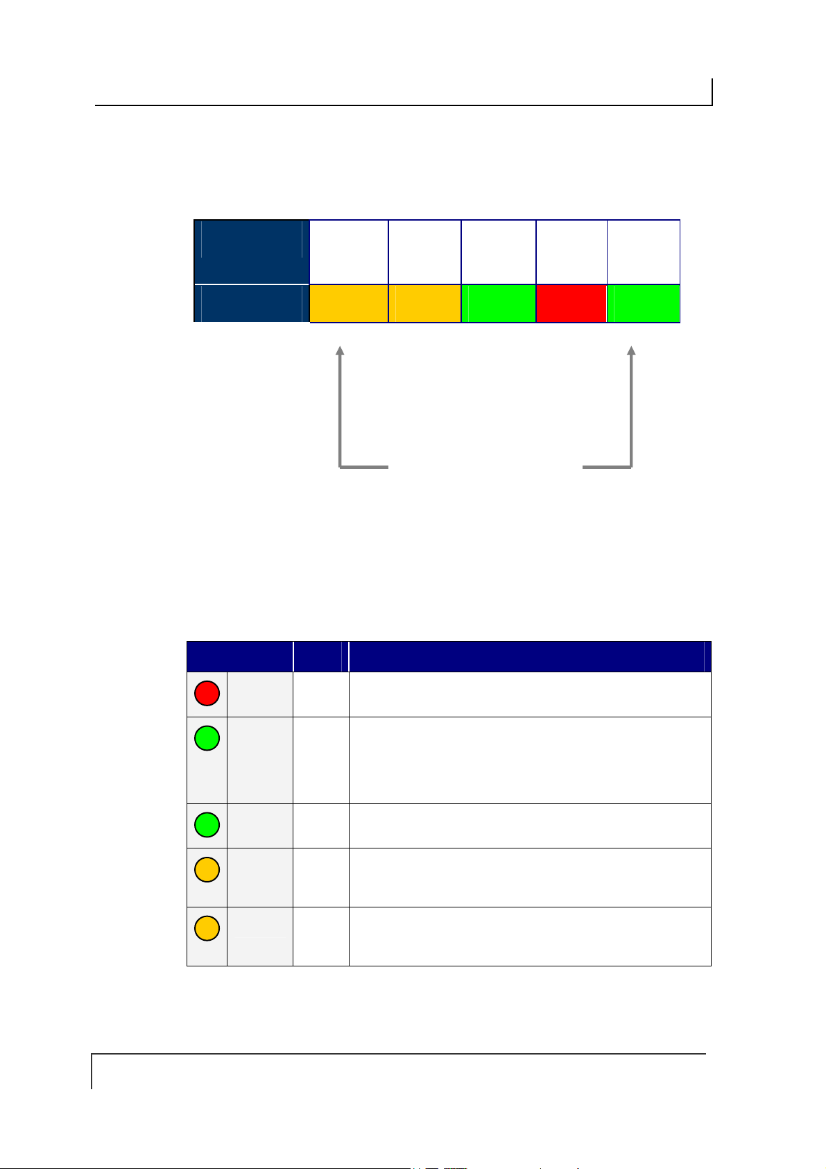
4.1.2 LED Behavior for Cobalt UHF-CNTL-485-02
The Cobalt UHF-485 RFID Controller has eight LED indicators conveniently located
on the front of the device, that convey visual information to the operator.
LED
FUNCTION
LED COLOR
16
Node
4)
(2
8
Node
(23)
4
Node
(22 )
2
Node
(21)
1
Node
(20)
PWR
Power
On
RF
Activity
COM
Activity
Amber Amber Amber Amber Amber Green Red Green
LEDs Description
LED COLOR NAME L ED DESCRIPTIO N
RED RF
GREEN COM
GREEN PWR
AMBER 16,8,4,2,1
(Node
LEDs)
Table 4-2: UHF-CNTL-485-02 - LEDs Description
The RF LED illuminates when RF power is being transmitted
by the antenna.
The COM (communications) LED flashes ON and OFF
when data is being transmitted between the antenna and a
tag.
When in Continuous Read mode, the COM LED will remain
ON and will turn OFF briefly only while data is being read
from or written to a tag.
The PWR (power) LED is ON whenever power is applied to
the Cobalt.
The five amber Node LEDs on the right side indicate the
current Subnet 16 address of the unit. In binary from bottom
to top, they indicate the current Node ID value assigned to
the controller.
For example, Node 9 will have: Led 16 OFF, Led 8 ON, Led
2 OFF, Led 1 ON
PAGE 43 OF 140
COBALT UHF-SERIES CHAPTER 4: LED STATUS
4.1.3 LED Behavior for Cobalt UHF-CNTL-IND-02
The Cobalt UHF-IND RFID Controller has fi ve LED indicators conveniently located
on the front of the device, th at convey visual information to the operator.
LED FUNCTION DEF IP
LED COLOR
Amber Amber Green Red Green
ACT IP
PWR
Power On
RF
Activity
COM
Activity
LEDs Description
LED COLOR NAME LED DESCRI PTION
RED RF
GREEN COM
GREEN PWR
AMBER DEF IP
AMBER ACT IP
Table 4-3: UHF-CNTL-IND-02 - LEDs Description
The RF LED illuminates when RF power is being transmitted by
the antenna.
The COM (communications) LED flashes ON and OFF when
data is being transmitted between the antenna and a tag.
When in Continuous Read mode, the COM LED will remain ON
and will turn OFF briefly only while data is being read from or
written to a tag.
The PWR (power) LED is ON whenever power is applied to the
Cobalt.
The DEF IP LED indicate the status of the IP address in the
unit. It illuminates when the IP address of the unit is the default
one: 192.168.253.110
The ACT IP LED indicate the status of the IP address in the
unit. It illuminates when the IP address of the unit is not the
default one, but one chosen by the user.
PAGE 44 OF 140

COBALT UHF-SERIES CHAPTER 5: COMMAND PROTOCOLS
CHAPTER 5:
COMMAND PROTOCOLS
5.1 COMMAND PROTOCOLS OVERVIEW
In order to execute RFID commands properly, the Cobalt UHF and host computer
must be able to communicate using the same language. The language that is used to
communicate is referred to as the Command Protocol.
When an RFID command is issued, the host computer instructs the RFID controller to
perform a given task. After performing that task, the RFID controller will normally
reply back with a Command Response message indicating the status or results of the
attempted command. This response notifies the host as to whether the command
was successfully completed or if the RFID controller failed to complete the command.
The Cobalt RFID product line by Datalogic supports three basic command protocols:
CBx, ABx Fast and ABx Standard. To determine which command protocol to utilize
for the different versions of Cobalt UHF Series, please refer to the table below:
PRODUCT CBX ABX FAST ABX STANDARD
UHF-CNTL-232-02 X X
UHF-CNTL-IND-02 X
UHF-CNTL-485-02 X
Table 5-1: Command Protocol Matrix
NOTE: RS485-based RFID controllers are used in conjunction with Subnet16 Gateway
and Subnet16 Hub interface modules, which use the CBx Command Protocol.
PAGE 45 OF 140

COBALT UHF-SERIES CHAPTER 5: COMMAND PROTOCOLS
5.2 RFID COMMAND TABLE
This is a list of all the commands supported by the Cobalt UHF Series controllers:
COMMAND ID COMMAND NAME DESCRIPTION
Single-Tag RFID Commands
0x04 Fill Tag
0x05 Read Data
0x06 Write Data
0x07 Read Tag ID
0x08 Tag Search
0x0D
0x0E
0x0F
0xC2
Start Continuous
Read
Read Tag ID and
Data
Start Continuous
Read Tag ID and
Data
Read EPC Code
Fills a specified tag address range with a
one-byte value
Reads a specified length of data from a
contiguous (sequential) area of tag
memory
Writes a specified number of bytes to a
contiguous area of tag memory
Retrieves a tag’s unique identification (Tag
ID) number
Instructs the controller to search for a tag
in its RF field
Instructs the controller to start or stop
Continuous Read mode.
Reads a tag’s ID number as well as a
specified number of bytes of tag memory
Instructs the controller to start or stop
Continuous Read Tag ID and Data mode.
Retrieves the tag’s Electronic Product
Code Identity
0xC3
Write EPC Code
RFID Controller Commands
0x35 Reset Controller
0x36
0x37
0x38
0x51
Set Controller
Configuration
Get Controller
Configuration
Get Controller
Info
Set Controller
Time
PAGE 46 OF 140
Used to modify the tag’s factory default
Electronic Product Code Identity
Resets power to the controller
Used to set (configure or modify) the
controller’s configuration parameters and
settings
Retrieves the controller’s configuration
settings
Retrieves hardware, firmware and serial
number information from the contr o ller
Used to set the time for the controller

COBALT UHF-SERIES CHAPTER 5: COMMAND PROTOCOLS
COMMAND ID COMMAND NAME DESCRIPTION
0x56
0x57
0x70
0x71
0x72
0xC0
0xC1
Set Controller
Trigger
Get Controller
Trigger
Set Controller
Macro
Get Controller
Macro
Execute
Controller Macro
Set UHF
Configuration
Get UHF
Configuration
Used to set the parameters for one of the
controller’s eight triggers
Used to retrieve the parameters of one of
the controller’s eight triggers
Used to set the parameters for one of the
controller’s ei g ht macros
Used to retrieve the parameters of one of
the controller’s eight macros
Instructs the controller to execute one of its
eight macros
Used to set (configure or modify) the
controller’s UHF configuration parameters
and settings
Retrieves the controller’s UHF
configuration parameters
Multi-Tag RFID Commands
0x82 Multi-Tag Read
ID and Data All
0x85 Multi-Tag Block
Read All
Retrieves a contiguous segment of data and
the tag ID from all RFID tags in range
Retrieves a contiguous segment of data
from all RFID tags in range
0x87 Multi-Tag Get
Inventory
0xC4
Read EPC Code
Table 5-2: RFID Command Table
Retrieves the tag ID from all RFID tags in
range
Retrieves the Electronic Product Code
Identities for all tags in range (multi-tag
inventory)
PAGE 47 OF 140

COBALT UHF-SERIES CHAPTER 5: COMMAND PROTOCOLS
5.2.1 RFID Commands - Note About the UHF-G2-525xx Tag
Memory Structure
The memory in Datalogic’s EPC Class 1 Gen 2 tag UHF-G2-525xx is organized in three
areas:
NAME DESCRIPTION SIZE
EPC
TID
USER
EPC memory according to
the EPCglobal standard
Read Only Unique identifier 64 bits ( 8 bytes )
User memory 512 bit ( 64 bytes )
Table 5-3: UHF-G2-525xxx Tag Memory Structure
96 bit ( 12 bytes )
EPC
EPC is a numbering scheme that allows assignment of a unique identifier to any
physical object. It can be regarded as the next generation of Universal Product Code
(UPC), which is used on most products today.
EPC enables the means to assign a unique identifier to each item, thus allowing
every item to be uniquely identified.
To have more details on the structure of the EPC memory area please consult:
EPC Radio-Frequency Identity Protocols Class-1 Generation-2 UHF RFID Protocol
for Communications at 860 Mhz – 960 Mhz, Version 1.1.0 (December 17, 2005)
In our UHF-G2-525xx tag this memory area is preprogrammed with the TID unique
identifier and padded with zeroes. The user can change that but it’s important to note
that only tags with different EPC codes will be discriminated in a multitag reading
environment.
TID
This is a read-only area that holds a unique tag identifier number. This area can be
accessed using the common ABx/CBx Read ID commands.
USER
This is the normal data area that can be accessed using the common ABx/CBx
Read and Write commands.
NOTE: The fastest access memory is the EPC area. For applications where speed is
important the use of this memory is recommended.
PAGE 48 OF 140

COBALT UHF-SERIES CHAPTER 5: COMMAND PROTOCOLS
5.3 ABX COMMAND PROTOCOL OVERVIEW
There are two versions of the ABx Command Protocol that are supported by the
Cobalt UHF Serial Controller, they are:
ABx Fast (default)
ABx Standard
The ABx Fast Command Protocol has a single-byte based packet structure that
permits the execution of RFID commands while requiring the transfer of fewer total
bytes than ABx Standard. ABx Fast is the default command protocol used by Cobalt
UHF Serial RFID Controller. It can be used with or without a checks um byt e.
The ABx Standard Command Protocol
shares a common syntax with most exis ting RF ID s ystem s produced by Escort
Memory Systems. This protocol offers legacy support, w hich may be required by
existing PLC applications that only support a 2-byte word packet format. If your
application requires compatibility with existing or legacy RFID devices from
Datalogic’s EMS product line, use ABx Standard. ABx Standard does not support the
use of a checksum byte.
NOTE:
By default, the UHF-CNTL-232-02 is configured to use the ABx Fast Command
Protocol. ABx Fast (as the name suggests) is the faster and more efficient of the two
ABx protocols, offering increased communication speed and error immunity.
uses a double-byte, word based format that
5.3.1 ABx Command Packet Structure
All ABx-based RFID commands contain certain fundamental packet elements,
including a
Parameters (when applicable) and a Command Terminator.
Command Packet Structure = [Command Header + Command ID + Command
Parameters + Command Terminator]
Command Header, a Command ID, one or more Command
5.3.2 ABx Protocols - Headers and Terminators
In ABx Standard, commands begin with the one-byte command header "0xAA," and
end with the two-byte command terminator "0xFF, 0xFF".
In ABx Fast, commands begin with the two-byte command header “0x02, 0x02” and
end with the one-byte command terminator “0x03.”
See the table below for further clarification.
ABx Protocols - Headers and Terminators
ABX PROTOCOL HEADER TERMINATOR
ABx Fast
ABx Standard
Table 5-4: ABx Protocols - Headers and Terminators
PAGE 49 OF 140
0x02, 0x02 0x03
0xAA 0xFF, 0xFF
COBALT UHF-SERIES CHAPTER 5: COMMAND PROTOCOLS
When a command is issued by the host, the RFID controller stores the incoming data
packet in a buffer while it scans the data for a start character (0x02, 0x02 or 0xAA).
When a start character is found, it checks for the proper terminator (0x03 or 0xFF,
0xFF). Having identified a potentially valid command string, the controller will verify
the format of the data and either perform the requested function or generate an error
message.
5.3.3 ABx Response Packet Structure
After completing an ABx command, the RFID controller generates a host-bound,
response packet that indicates the status and/or results of the attempted command.
The response packet structure for all ABx protocols consists of a Response Header,
a Command Echo, one or more Response Values (when applicable), and a
Response Terminator.
Response Packet Structure = [Response Header + Command Echo + Response
Values + Response Terminator]
Note that, for each ABx protocol, response header and response terminator
parameters are the same as their command header and command terminator
counterparts.
ATTENTION: This Cobalt UHF Series Manual does NOT contain descriptions or
examples of each supported RFID command common to all the devices in the Cobalt
family. For complete details regarding the use of common RFID commands please visit
www.ems-rfid.com and download the ABx Standard Command Protocol – Reference
Manual or the ABx Fast Command Protocol – Reference Manual. Here you will find
only the commands that are specific to the UHF controller.
PAGE 50 OF 140

COBALT UHF-SERIES CHAPTER 5: COMMAND PROTOCOLS
5.4 ABX FAST COMMAND PROTOCOL
The default command protocol used by UHF-CNTL-232-02 RFID Controllers for
Point-to-Point data transmission is known as the ABx Fast Command Protocol.
ABx Fast has a single-byte oriented packet structure that permits the rapid execution
of RFID commands while requiring the transfer of a minimal number of bytes.
ABx Fast supports the inclusion of an optional checksum byte. When increased data
integrity is required, the checksum should be utilized. See Section 5.4.3 “Command
Packet Elements” for more on using the checksum parameter.
5.4.1 ABx Fast - Command / Response Procedure
After an RFID command is issued by the host, a packet of data, called the
“Command Packet” is sent to the controller. The command packet contains
information that instructs the controller to perform a certain task.
The controller automatically parses the incoming data packet, searching for a specific
pair of start characters, known as the “Command Header.” In ABx Fast, the
Command Header / Start Characters are 0x02, 0x02. When a valid Command
Header is recognized, the controller then checks for proper formatting and for the
presence of a Command Terminator byte. In ABx Fast, the Command Terminator
byte is 0x03.
Having identified a valid command, the controller will attempt to execute the given
instructions. After which the controller will generate a host-bound response message
containing EITHER the results of the attempted command or an error code if the
operation failed.
Note that all commands generate a response from the controller. Before sending a
second or additional command to a controller, allow the host to first process (remove
from memory) any pending response data.
Table 5-5: ABx Fast - Command Packet Structure
PAGE 51 OF 140
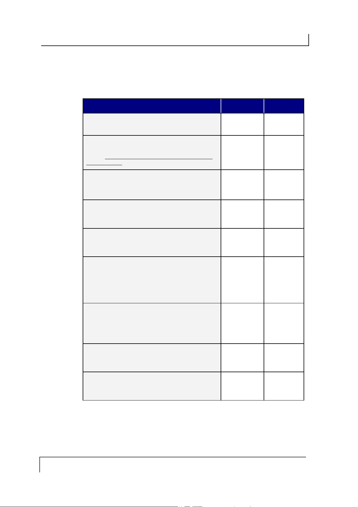
COBALT UHF-SERIES CHAPTER 5: COMMAND PROTOCOLS
5.4.2 ABx Fast - Command Packet Structure
The packet structure of all ABx Fast RFID commands contains certain basic
elements, including Command Header, Command Size, Command ID and
Command Terminator. Packet element and parameter availability depends on the
command being performed.
COMMAND PACKET ELEMENT CONTENT SIZE
COMMAND HEADER
The first two bytes of an ABx Fast command.
COMMAND SIZE
This two-byte integer defines the number of bytes in the
packet (excluding Header, Command Size, Checksum
and Terminator).
COMMAND ID:
This single-byte value indicates the RFID command to
execute.
START ADDRESS
This two-byte integer indicates the location of tag
memory where a read or write operation shall begin.
BLOCK SIZE
This two-byte integer represents the number of bytes
that are to be read from or written to the RFID tag.
TIMEOUT VALUE
This two-byte integer indicates the maximum length of
time for which the controller will attempt to complete the
command. Measured in milliseconds, this value can
have a range of 0x0001 to 0xFFFE or between 1 and
65,534 msecs.
:
:
:
:
:
0x02, 0x02 2 bytes
0x0007 +
(number of
bytes of
additional data)
0x06
(Write Data)
0x0000 2-byte integer
0x0001 2-byte integer
0x07D0
(0x07D0 =
2000 x .001 =
2 seconds)
2-byte integer
1 byte
2-byte integer
ADDITIONAL DATA
This parameter uses one byte to hold a single character
for fill operations and supports the use of multiple bytes
when several characters are needed for write
commands (when applicable).
CHECKSUM
This optional parameter holds a single-byte checksum
(only applicable when using ABx Fast with Checksum).
COMMAND TERMINATOR
The single-byte command packet terminator is always
0x03 for ABx Fast.
:
:
:
Table 5-6: ABx Fast - Command Packet Structure
PAGE 52 OF 140
0x00 1 or more
bytes
Optional 1 byte (when
applicable)
0x03 1 byte

COBALT UHF-SERIES CHAPTER 5: COMMAND PROTOCOLS
5.4.3 ABx Fast – Command Packet Elements
Command Size
The ABx Fast protocol requires that the byte count, known as the Command Size,
be specified as a two-byte integer within each command packet. To calculate the
Command Size, add the total number of bytes within the command packet while
excluding the two byte Command Header, the two byte Command Size, the one byte
Checksum (if present) and the one byte Command Terminator (see example below).
Command
Size =
number of
bytes in these
fields
COMMAND PACKET
ELEMENT
Command Header 2 No
Command Size 2 No
Command ID 1 Yes
Start Address 2 Yes
Read/Block Size 2 Yes
Timeout Value 2 Yes
Additional Data Bytes 1 Yes
Checksum 1 No
Command Terminator 1 No
Table 5-7: ABx Fast - Command Size Parameter
# OF BYTES INCL UDED IN COMMAND
SIZE?
(if present)
In the above sample comma nd packet, there are eight bytes of data (located
between the Comman d S i z e parameter and the Checksum parameter) that are
included in the Command Size. Therefore, the Command Size for this example is
0x0008.
Command ID
The one-byte Command ID parameter identifies the Hex value of the RFID
command to perform. (See the Section 5.2 - ABx Fast RFID Command Table
.)
Start Address
The Start Address parameter holds a tw o-b yte intege r re pres e n tin g the tag memory
address location where a read or write operation is to begin.
Block Size (Read/Write Length)
The two-byte Block Size parameter (which is also sometimes called the Read /
Write Length parameter) indicates the number of bytes that are to be read from or
written to the RFID tag.
PAGE 53 OF 140

COBALT UHF-SERIES CHAPTER 5: COMMAND PROTOCOLS
Timeout Value
Most ABx Fast commands include a two-byte Timeout Value, which is used to limit
the length of time that the Cobalt UHF will attempt to complete the specified
operation.
The Timeout Value is measured in 1-millisecond increments and has a maximum
supported value of 0xFFFE or 65,534 milliseconds (which is slightly longer than one
minute).
Setting a long Timeout Value does not necessarily mean that a command will take
any longer to execute. This value only represents the period of time for which the
Cobalt UHF will attempt execution of the command.
IMPORTANT:
During write commands, the tag must remain within the antenna’s RF field until the
write operation completes successfully, or until the Timeout Value has expired.
If a write operation is not completed before the tag leaves the controller’s RF field, data
may be incompletely written.
Checksum
The ABx Fast Command Protocol supports the inclusion of an optional Checksum
byte that is used to verify the integrity of data being transmitted between host and
controller.
The Checksum is calculated by adding together (sum m ing ) th e byte values in the
command packet (less the Command Header, Checksum and Command Terminator
parameters), and then subtracting the total byte sum from 0xFF.
Therefore, when the byte values of each parameter (from Command Size to
Checksum) are added together, the byte value sum will equal 0xFF.
PAGE 54 OF 140

COBALT UHF-SERIES CHAPTER 5: COMMAND PROTOCOLS
CHECKSUM E XAMPLE
The following example depicts Command 0x05 (Read Data) when using a
Checksum.
Checksum
= [0xFF –
(sum of
these fields)]
COMMAND
ELEMENT
Header 0x02, 0x02 n/a
CONTENTS USED IN CHECKSUM
Command Size 0x0007 0x00, 0x07
Command ID 0x05 0x05
Start Address 0x0001 0x00, 0x01
Block Size 0x0004 0x00, 0x04
Timeout Value 0x07D0 0x07, 0xD0
Checksum
Terminator 0x03 n/a
0x17
Table 5-8: ABx Fast - Checksum Example
n/a
Add the byte values from the Command Size, Command ID, Start Address, Block
Size and Timeout Value parameters together and subtract from 0xFF. The resulting
value will be the Checksum.
[0x07
+ 0x05 + 0x01 + 0x04 + 0x07 + 0xD0] = 0xE8
The checksum equation is: [0xFF
– 0xE8] = 0x17
PAGE 55 OF 140

COBALT UHF-SERIES CHAPTER 5: COMMAND PROTOCOLS
5.4.4 ABx Fast - Multi-Tag Command Packet Structure
Multi-tag (anti-collision) commands are used to communicate with one or more RFID
tags, when numerous tags are simultaneously within RF range. ABx Fast Multi-tag
commands are formatted as follows:
COMMAND PACKET ELEMENT CONTENT SIZE
COMMAND HEADER
The first two bytes of an ABx Fast command.
COMMAND SIZE
This two-byte integer defines the number of bytes in the
packet (excluding Header, Command Size and
Terminator).
COMMAND ID:
This single-byte value indicates the RFID command to
execute.
Reserved for future use
Reserved for future use
TAG LIMIT:
This single byte specifies the maximum # of tags
expected in RF range, up to 100; 0x64 = 100 tags
expected max (when applicable)
START ADDRESS
This two-byte integer indicates the location of tag
memory where a read or write operation shall begin.
BLOCK SIZE (READ/WRITE LENGTH
This two-byte integer represents the number of bytes that
are to be read from or written to the RFID tag.
TIMEOUT VALUE
This two-byte integer indicates the maximum length of
time for which the controller will attempt to complete the
command. Measured in milliseconds, this value can have
a range of 0x0001 to 0xFFFE or between 1 and 65,534
msecs.
ADDITIONAL DATA
This parameter uses one byte to hold a single character
for fill operations and supports the use of mult iple bytes
when several characters are needed for write commands
(when applicable).
COMMAND TERMINATOR
The single-byte command packet terminator is always
0x03 for ABx Fast.
:
:
:
):
:
:
:
Table 5-9: ABx Fast - Anti-Collision Command Packet Structure
0x02, 0x02 2 bytes
0x0007 +
(number of bytes
of additional
data)
0x06
(Write Data)
0x00 1 byte
0x00 1 byte
0x64 1 byte
0x0000 2-byte
0x0001 2-byte
0x07D0
(0x07D0 = 2000
x .001 = 2
seconds)
0x00 1 or
0x03 1 byte
2-byte
integer
1 byte
integer
integer
2-byte
integer
more
bytes
PAGE 56 OF 140

COBALT UHF-SERIES CHAPTER 5: COMMAND PROTOCOLS
5.4.5 ABx Fast - Multi-Tag Command Packet Elements
Tag Limit
The Tag Limit parameter holds a one-byte value that indicates the maximum number
of tags expected simultaneously in RF range for the given command operation.
This parameter allows users to limit the number of attempted read/write operations
the controller will make per execution. Users do not have to wait for the timeout to
expire.
The Tag Limit value should be set in relation to the maximum number of tags that
could possibly be present in the reading field at any one time. Setting the value
higher increases the number of tags expected to be read in the antenna’s RF field.
Lowering the value, however, can speed up tag read operations for a small group of
tags. Setting the proper val ue is therefore a tradeoff between the number of
expected tags in the reading field, and the time required to read/write to them. The
permitted values range from zero to 100 (0x00 – 0x64). The Tag Limit parameter
resides directly after the “Anti-collision Mode” parameter in the command string
(when applicable).
Timeout Value
Multi-tag commands also contain a two-byte Timeout Value parameter that is used to
limit the length of time for which the Cobalt will attempt to complete a given operation.
It is important to set a realistic Timeout Value that permits enough time for the Cobalt
to read/write to all tags specified in the command. Processing multiple-tag operations
requires a longer time period than does the exe cu tio n of si ngle -tag c omm and s.
The value is expressed in one-millisecond increments, with a maximum value of
0xFFFE (65,534 milliseconds) or approximately 60 seconds. For most single tag
read/write commands, a Timeout Value of at least 1000ms is recommended.
However, it is recommended that you allow an additional 100ms per tag for multi-tag
read operations and 150ms per tag for multi-tag writes.
Timeout Value Example
When writing to 16 different tags in RF range, for example, set the two-byte Timeout
Value to at least 0x0D48 (16 x 150ms + 1000ms = 3400ms or 3.4 seconds). A
Timeout Value of zero (0x0000) will cause the Cobalt to return a syntax error
message.
Using a Timeout Value that is too short may result in diminished read/write range.
Setting a long Timeout Value does not necessarily mean that the command will take
any longer to complete. The value only represents the period of time in which the
Cobalt will attempt to complete the particular operation. If all required tags are in RF
range when the command is sent, the time necessary to complete the command will
be approximately the same whether the Timeout Value is 1000ms or 10,000ms.
For time critical applications, the optimal Timeout Value should be obtained through
rigorous performance testing.
PAGE 57 OF 140

COBALT UHF-SERIES CHAPTER 5: COMMAND PROTOCOLS
5.4.6 ABx Fast - Response Packet Structure
After performing a command, the Cobalt UHF will generate a host-bound response
packet. ABx Fast responses contain a Response Header, Response Size,
Command Echo, one or more Response Values / Retrieved Data (when
applicable), and a Response Terminator.
RESPONSE PACKET ELEMENT CONTENT SIZE
RESPONSE HEADER:
The first two bytes of an ABx Fast response packet
RESPONSE SIZE:
This two-byte integer indicates the total number of
bytes in the response packet (excluding Response
Header, Response Size, Checksum and Terminator).
COMMAND ECHO:
This single-byte parameter reiterates the Hex value of
the command for which the response packet was
generated.
RESPONSE VALUES / RETRIEVED DATA:
This parameter is used to hold one or more bytes of
the data that was requested by the command (when
applicable).
CHECKSUM:
This optional parameter holds a single-byte checksum
(only applicable when using ABx Fast with
Checksum).
RESPONSE TERMINATOR:
Single-byte response packet terminator (always 0x03)
0x02, 0x02 2 bytes
0x0001 +
(number of bytes
of retrieved data)
0x06 1 byte
Data 1 or more bytes
Optional 1 byte
0x03 1 byte
2-byte integer
(when
applicable)
(when
applicable)
Table 5-10: ABx Fast - Response Packet Structure
PAGE 58 OF 140

COBALT UHF-SERIES CHAPTER 5: COMMAND PROTOCOLS
5.4.7 ABx Fast Protocol:
Error Response Packet Structure
ABx Fast error responses contain a two-byte Response Header, a two-byte
Response Size parameter followed by a single-byte Error Flag (0xFF), a single-byte
Error Code, which identifies the error that occurred, and a single-byte Response
Terminator.
ERROR RESPONSE ELEMENT CONTENT
Response Header
Response Size
Error Flag
Error Code
Checksum
Response Terminator
Table 5-11: ABx Fast - Error Response Structure
0x02, 0x02
0x0002
0xFF
<1-byte error code>
Optional
0x03
ABX FAST - ERROR RESPONSE EXAMPLE
Below is an example of an ABx Fast error response for a failed Write Data operation
(Error Code 0x06).
ERROR RESPONSE ELEMENT CONTENT
Response Header
Response Size
0x02, 0x02
0x0002
Error Flag
Error Code
Checksum
Response Terminator
0xFF
0x06
Optional
0x03
PAGE 59 OF 140

COBALT UHF-SERIES CHAPTER 5: COMMAND PROTOCOLS
SINGLE-TAG RFID COMMAND 0XC2:
READ EPC CODE
COMMAND 0X C2 – D ESCRIPTION
The Read EPC Command instructs the controller to retrieve the EPC memory area
of a single tag UHF Class1 Gen2.
C
OMMAND 0XC2 - ABX F AST E XAMPLE
This example instructs the controller to read the EPC memory from a tag. A Timeout
Value of 2 seconds (0x07D0 = 2000 x one-millisecond increments) is set for the
completion of the command.
Command from Host
PARAMETER FIELD CONTENT
Header
Command Size
Command ID
Timeout Value
Terminator
0x02, 0x02
0x0003
0xC2
0x07D0
0x03
Response from Controller
PARAMETER FIELD CONTENT
Header
Response Size
Command Echo
EPC byte 1
EPC byte 2
EPC bytes 3… to 11
0x02, 0x02
0x000D
0xC2
0x05
0xAA
……..
EPC byte 12
Terminator
0x07
0x03
PAGE 60 OF 140

COBALT UHF-SERIES CHAPTER 5: COMMAND PROTOCOLS
SINGLE-TAG RFID COMMAND 0XC3:
WRITE EPC CODE
COMMAND 0X C3 – D ESCRIPTION
The Write EPC Command instructs the controller to write the EPC memory area of a
single tag UHF Class1 Gen2.
C
OMMAND 0XC3 - ABX F AST E XAMPLE
This example instructs the controller to write the specified bytes in the EPC memory
of a tag. A Timeout Value of 2 seconds (0x07D0 = 2000 x one-millisecond
increments) is set for the completion of the command.
Command from Host
PARAMETER FIELD CONTENT
Header
Command Size
Command ID
EPC Data Byte Value 1
EPC Data Byte Value 2
EPC Data Byte Value 3… to 11
EPC Data Byte Value 12
Timeout Value
Terminator
0x02, 0x02
0x000F
0xC3
0x48
0x45
…….
0x4C
0x07D0
0x03
Response from Controller
PARAMETER FIELD CONTENT
Header
Response Siz e
0x02, 0x02
0x0001
Command Echo
Terminator
0xC3
0x03
PAGE 61 OF 140

COBALT UHF-SERIES CHAPTER 5: COMMAND PROTOCOLS
MULTI-TAG RFID COMMAND 0XC4:
READ EPC CODE
COMMAND 0X C4 – D ESCRIPTION
The Multi-Tag Read EPC Code is used to retrieve the EPC data from all tags within
RF range. A final termination packet is sent when the Timeout Value expires.
C
OMMAND 0X C4 - ABX FAST EXAMPLE
This example instructs the controller to read the EPC data from each tag in range. A
Timeout Value of 3 seconds (0x0BB8 = 3000 x 1msec increments) is set for the
completion of the command.
Command from Host
PARAMETER FIELD CONTENT
Command Header
Command Size
Command ID
Timeout Value
Command Terminator
0x02, 0x02
0x0003
0xC4
0x0B, 0xB8
0x03
Response for Each Tag Read
PARAMETER FIELD CONTENT
Response Header
Response Siz e
Command Echo
EPC Read Data Byte 1
EPC Read Data Byte 2
0x02, 0x02
0x000D
0xC4
<D01>
<D02>
. . .
EPC Read Data Byte 12
Response Terminator
. . .
<D12>
0x03
PAGE 62 OF 140

COBALT UHF-SERIES CHAPTER 5: COMMAND PROTOCOLS
Final Termination Packet
PARAMETER FIELD CONTENT
Response Header
Response Siz e
Final Termination Packet Identifier
Number of Tags Read
Status
Response Terminator
0x02, 0x02
0x0004
0xFF
<N-tags>
0x0000
0x03
PAGE 63 OF 140
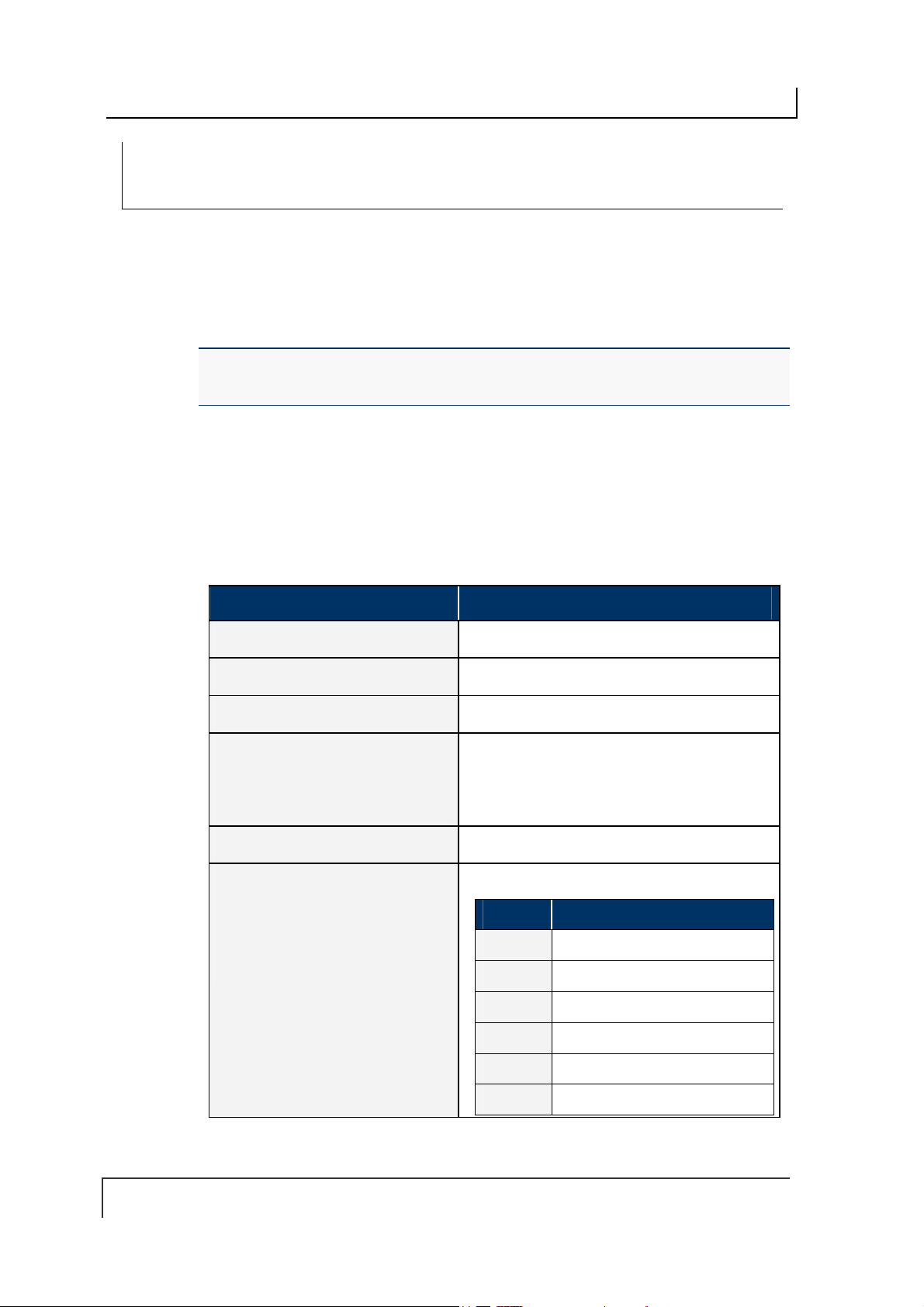
COBALT UHF-SERIES CHAPTER 5: COMMAND PROTOCOLS
CONTROLLER SPECIFIC COMMAND 0X C0:
SET UHF CONFIGURATION
COMMAND 0X C0 – D ESCRIPTION
The Set UHF Configuration command is used to set (configure or modify) the
controller’s UHF configuration parameters and settings to the controller’s flash
memory.
IMPORTANT: it is recommended that users first run Command 0xC1: Get UHF
Configuration and make note of their current controller configuration values prior to
executing this command.
OMMAND 0XC0 - ABX F AST E XAMPLE
C
This example permits the user to modify or write the indicated configuration settings
to the controller’s flash memory. The total number of bytes available for this purpose
is nine.
Command from Host
PARAMETER FIELD CONTENT
Command Header
Command Size
Command ID 0xC0
UHF Configuration Bytes 1 & 2
This two-byte integer represents the
Reader Outp ut Power
to 500 mW).
UHF Configuration Byte 3…to 7
UHF Configuration Byte 8
This byte permits the user to select
the specific
which commands are transmitted. The
user can write a value between o and
9 in bits from 4 to 7.
UHF channel
( value from 0
through
0x02, 0x02
0x000A
<2-bytes integer>
<Reserved> *
<Partially Reserved>
BIT Description
0
1
2
Reserved*
Reserved*
Reserved*
3
4 <Channel ID value>
5 <Channel ID value>
PAGE 64 OF 140
Reserved*
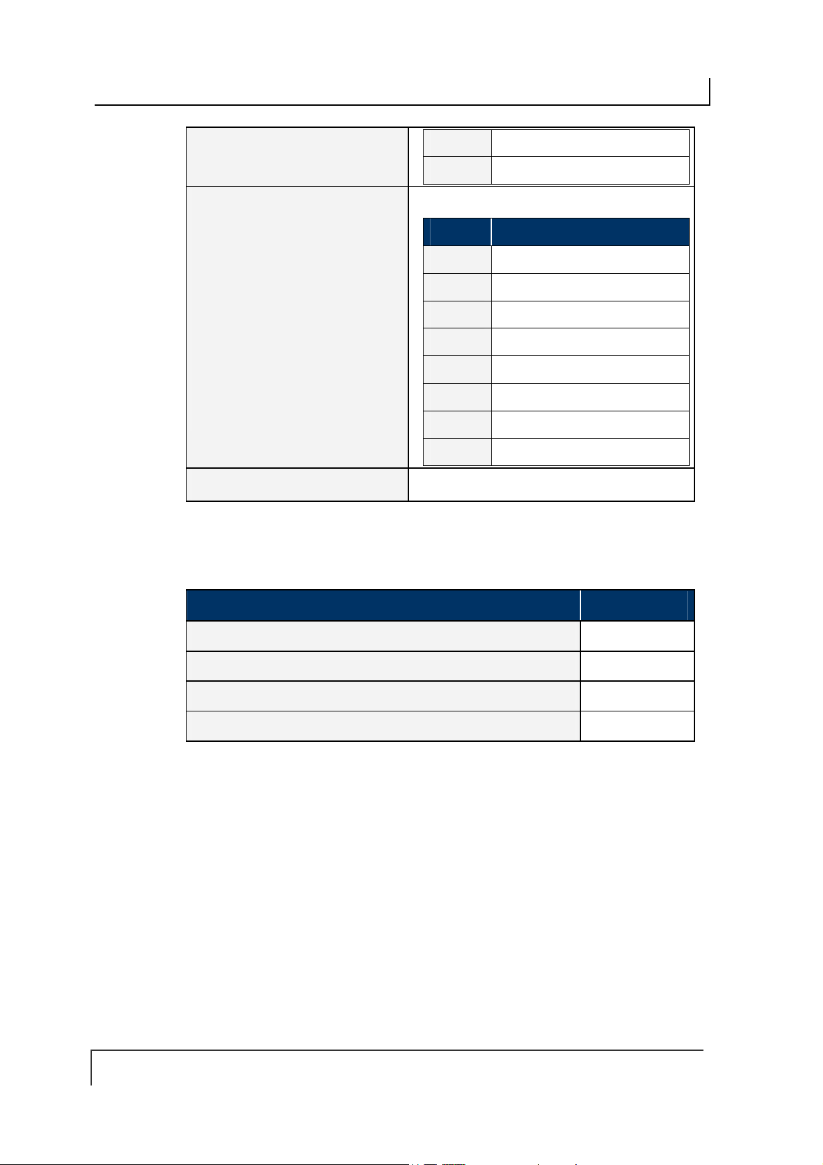
COBALT UHF-SERIES CHAPTER 5: COMMAND PROTOCOLS
6 <Channel ID value>
7 <Channel ID value>
UHF Configuration Byte 9
This byte permits the user to
enable/disable the
property.
One
If the Choose Nearest One property is
disabled
generated whenever a single-tag
read/write command is executed in a
multi-tag environment.
If the Choose Nearest One property is
enabled
executed on the tag with the stronger
signal.
, an error response is
, the read/write command is
Choose Nearest
<Partially Reserved>
BIT Description
0
1 <Choose Nearest One option>
2
3
4
5
6
Reserved*
Reserved*
Reserved*
Reserved*
Reserved*
Reserved*
Reserved*
Command Terminator
7
0x03
*Leave the default value retrieved through Command 0xC1: Get UHF Configuration
Response from Controller
PARAMETER FIELD CONTENT
Header
Response Siz e
Command Echo
Terminator
0x02, 0x02
0x0001
0xC0
0x03
PAGE 65 OF 140
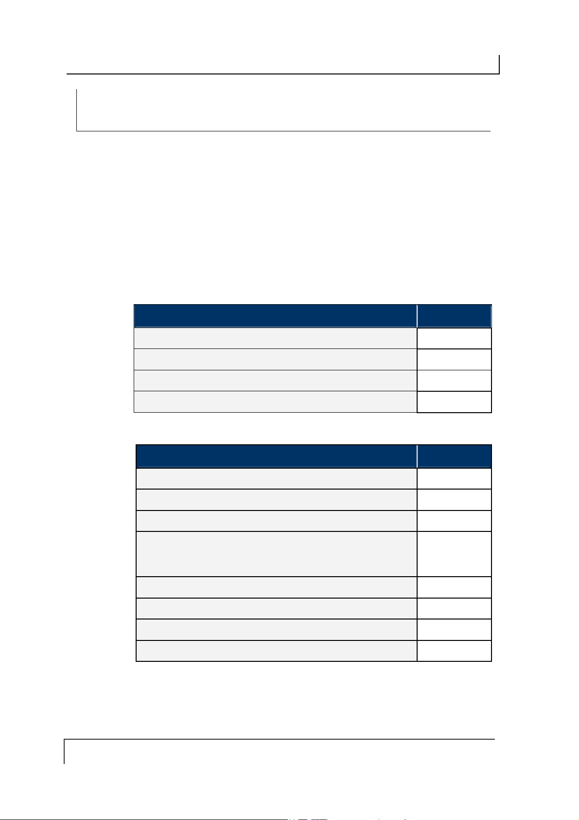
COBALT UHF-SERIES CHAPTER 5: COMMAND PROTOCOLS
CONTROLLER SPECIFIC COMMAND 0X C1:
GET UHF CONFIGURATION
COMMAND 0X C1 – D ESCRIPTION
The Get UHF Configuration Command instructs the controller to retrieve the
controller’s UHF configuration parameters and settings stored in the unit’s flash
memory. These are the same values that are set with Command 0xC0: Set UHF
Configuration.
C
OMMAND 0XC1 - ABX F AST E XAMPLE
Through this command, the user queries a Cobalt UHF RFID controller and reads the
controller’s UHF configuration data from its flash memory.
Command from Host
PARAMETER FIELD CONTENT
Header
Command Size
Command ID
Terminator
0x02, 0x02
0x0001
0xC1
0x03
Response from Controller
PARAMETER FIELD CONTENT
Header
Response Size
Command Echo
UHF Bytes 1 & 2
This two-byte integer represents the
mW).
UHF Byte 3
EPC bytes 4… to 8
Reader Output Power
(0÷500
0x02, 0x02
0x000B
0xC1
<2-bytes value>
<1-byte value>
……..
EPC byte 9
Terminator
<1-byte value>
0x03
PAGE 66 OF 140
COBALT UHF-SERIES CHAPTER 5: COMMAND PROTOCOLS
5.5 CBX COMMAND PROTOCOL
The CBx Command Protocol is based on a double-byte oriented packet s truc ture
where commands always contain a minimum of six data “words,” even when one or
more parameters are not applicable to the command. CBx does not support the
inclusion of a checksum byte.
The CBx Command Protocol, utilized by Cobalt UHF-CNTL-IND-02 and (when
connected to a Gateway or Hub interface mo dule) UHF-CNTL-485-02 models,
includes Multidrop Subnet16™ networking support for use with Industrial Ethernet
applications.
Moreover, the packet structures described herein are protocol independent and can
be implemented the same for all Ethernet protocols (Ethernet/IP, Modbus TCP and
Standard TCP/IP protocol).
5.5.1 CBx - Command Procedure
Cobalt UHF-CNTL-485-02 Command Procedure
For the Cobalt UHF-CNTL-485-02, controller-bound commands are initiated by a hos t
computer or Programmable Logic Controller (PLC) and are delivered to the controller
by a Subnet16 Gateway or Subnet16 Hub Interface Module that is connected to the
host or PLC by standard Ethernet cabling.
Each Cobalt UHF-CNTL-485-02 connected to a Multi-drop Subnet16 network is
assigned an individual Node ID number between 1 and 16.
When a controller-bound command is issued, the instructions are retrieved by the
interface module (Gateway or Hub) and distributed to the correct RFID controller by
specifying the “Node ID” number of the particular controller.
Cobalt UHF-CNTL-IND-02 Command Procedure
For the Cobalt UHF-CNTL-IND-02, commands are initiated by a host computer or
Programmable Logic Controller (PLC) and are retrieved by the controller via Ethernet
connection.
Commands are directed to the Cobalt by specifying, in the command packet, the
“Node ID” number of the Cobalt Controller. For the Cobalt UHF-CNTL-IND-02, the
Node ID will always be 01 (0x01).
ATTENTION: This Cobalt UHF Series Manual does NOT contain descriptions or
examples of each supported RFID command common to all the devices in the Cobalt
family. For complete details regarding the use of common RFID commands please visit
www.ems-rfid.com and download the CBx Command Protocol – Reference Manual.
Here you will find only the commands that are specific to the UHF controller.
PAGE 67 OF 140

COBALT UHF-SERIES CHAPTER 5: COMMAND PROTOCOLS
5.5.2 CBx - Command Packet Structure
As noted, CBx commands contain a minimum of six words. Below is the structure of
a standard CBx command packet.
Table 5-12: CBx Command Packet Structure
CBx Command Packet Structure
(MSB = Most Significant Byte, LSB = Least Significant Byte)
WORD # COMMAND PACKET ELEMENT MSB LSB
01
02
03
Overall Length:
the number of 16-bit “
command packet.
Note: this value will always be at least 6,
as each command has a minimum of 12bytes (or 6 words). Overall Length will
increase when additional data words are
used in the command (for fills, writes, etc.).
in MSB
0xAA
Command ID
indicates command to perform
in MSB
0x00
Node ID:
number of the device to which the
command is intended.
Note: this value must be 0x20 (Node ID
32) when the command is directed to a
Gateway or Hub, and must be 0x01 (Node
ID 01) when the command is directed to a
Cobalt IND controller.
2-byte integer indicating
” in the
words
: single-byte value in LSB
LSB value indicates the Node ID
0x00 0x06 +
(number of
additional data
words, if any)
0xAA <Command
ID>
0x00 <Node ID>
PAGE 68 OF 140

COBALT UHF-SERIES CHAPTER 5: COMMAND PROTOCOLS
04
05
06
07
08
Timeout Value:
representing the length of time allowed for
the completion of the command (when
applicable). Measured in one-millisecond
increments, the Timeout Value can have a
value of 0x0001 to 0xFFFE (1 - 65,534
milliseconds).
Start Address:
the location of tag memory where a read or
write operation will begin (when applicable)
Block Size:
number of bytes that are to be read from or
written to a tag during the operation (when
applicable)
Additional Data:
hold 2-bytes of data used for writes and
fills (when applicable)
Additional Data:
hold an additional 2-bytes of data for writes
(when applicable)
Table 5-13: CBx Command Packet Structure
2-byte integer
2-byte integer indicating
2-byte integer indicating the
(bytes 1 & 2) used to
(bytes 3 & 4) used to
<Timeout
MSB>
<Start MSB> <Start LSB>
<Size MSB> <Size LSB>
<D1> <D2>
<D3> <D4>
<Timeout
LSB>
5.5.3 CBx Response Packet Structure
After executing a comma nd, the controller will generate a host-bound response
message. The response message will contain EITHER the results of the attempted
command or an error code indicating the reason the operation could not be
completed successfully. Below is the struc ture of a standard CBx response packet.
CBx Response Packet Structure
WORD # RESPONSE PACKET ELEMENT MSB LSB
01
02
Overall Length:
the number of “
packet. This value will always be at least
6 words
0xAA
Command Echo:
identifies the command that was
performed.
.
in MSB
2-byte integer indicating
” in the response
words
single-byte LSB value
0x00 0x06 +
(number of
additional data
words
retrieved, if
any)
0xAA <Command
Echo>
PAGE 69 OF 140
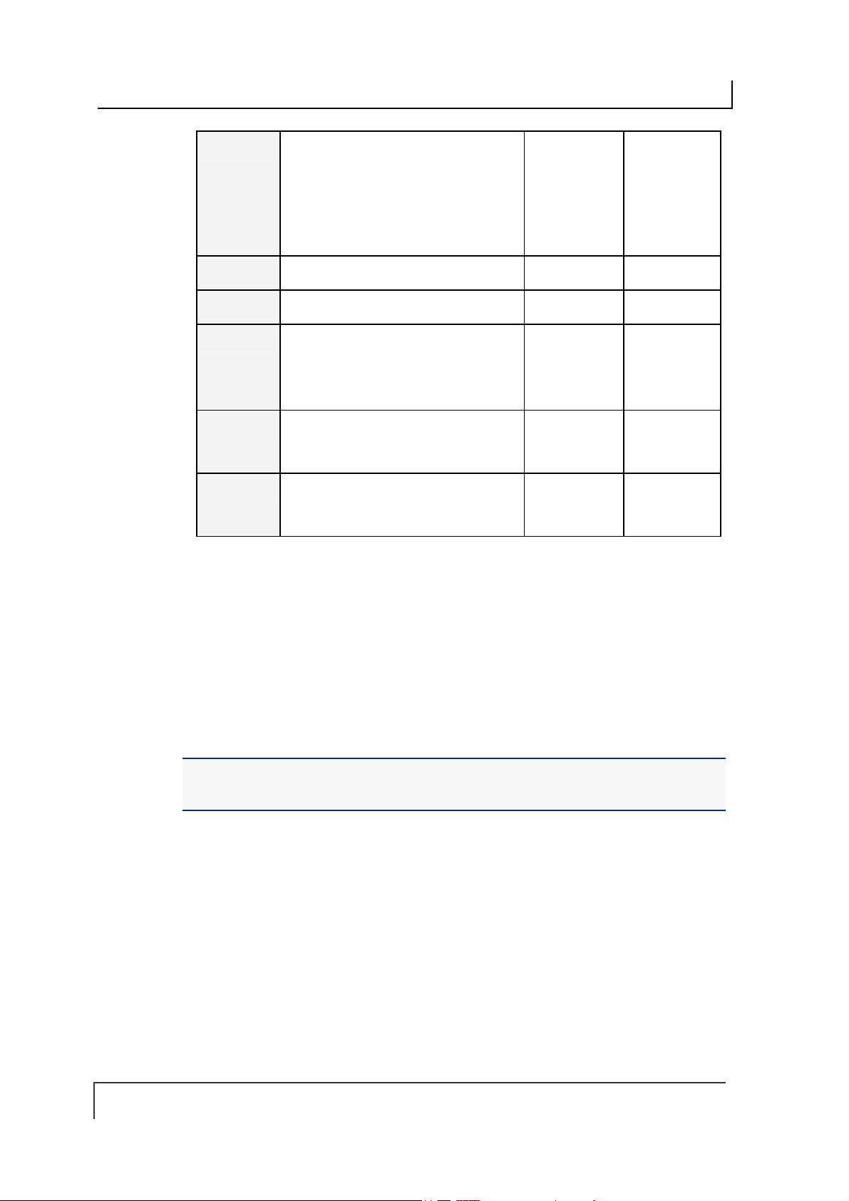
COBALT UHF-SERIES CHAPTER 5: COMMAND PROTOCOLS
03 Instance Counter:
(see description on following page)
Node ID Echo:
the Node ID of the device that performed
the command and/or generated the
response (will always be 0x20 for
Gateway/Hub, and 0x01 for Cobalt IND)
04
05
06
07
08
Month and Day Timestamp
Hour and Minute Timestamp
Second Timestamp
Additional Data Length:
indicates the number of additional bytes
retrieved (when applicable)
Retrieved Data:
hold 2-bytes of re trieved data (when
applicable)
Retrieved Data:
hold an additional 2-bytes of retrieved
data (when applicab le)
Table 5-14: CBx Response Packet Structure
in MSB
Value in LSB identifies
in MSB
Value in LSB
(bytes 1 & 2) used to
(bytes 3 & 4) used to
<Instance
Counter>
<Month> <Day>
<Hour> <Minute>
<Second> <Additional
<B1> <B2>
<B3> <B4>
<Node ID
Echo>
Data Length>
INSTANCE COUNTER
The Instance Counter is a one-byte value used to track the number of responses
generated by each Node ID. Instance Counter values are stored in the internal RAM
of the Gateway/Hub and are incremented by one following each response. If, for
example, the controller at Node 01 has generated 10 responses, the Instance
Counter value for Node 01 in the Gateway/Hub will read 10 (0x0A). When power is
cycled to the Gateway/Hub, the Instance Counter values for all nodes (and for the
Gateway/Hub itself) will be reset to zero (0x00).
NOTE: UHF-CNTL-IND-02 Controllers are capable of storing their own Instance
Counter values. Likewise, when power is cycled to either device, their Instance Counter
values will be reset to zero.
PAGE 70 OF 140

COBALT UHF-SERIES CHAPTER 5: COMMAND PROTOCOLS
5.5.4 CBx Multi-Tag Command Packet Structure
CBx Multi-tag Commands instruct a specified controller to read from or write to
several tags at once when multiple tags are simultaneously within RF range. It is also
possible to single-out and read from or write to one tag (identified by its unique tag ID
number) when multiple tag s are present in the RF field simultaneously.
Below is the structure of a basic CBx multi-tag command packet.
CBx Multi-tag Command Packet Structure
WORD # COMMAND PACKET ELEMENT MSB LSB
01 Overall Length
indicating the number of “
command packet.
02
03
04 Timeout Value
05 Start Address
in MSB
0xAA
Command ID
command to perform
in MSB
0x00
Node ID
number of the controller to which the
command is intended (must be 0x01 for –
Cobalt IND models)
the maximum length of time allowed for
the completion of the command,
measured in one-millisecond increments,
where 0x0BB8 = 3000 x .001 = 3
seconds. The Timeout Value can have a
value of 0x0001 to 0xFFFE (1 - 65,534
milliseconds).
the location of tag memory where a read
or write operation will begin (when
applicable).
: LSB value indicates the Node ID
: 2-byte integer value
” in the
words
: LSB value indicates
: 2-byte integer represents
: 2-byte integer indicating
0x00 0x08 + (number
of any additional
data words)
0xAA <Command ID>
0x00 0x01
0x0B 0xB8
<Start MSB> <Start LSB>
06 Block Size
number of bytes that are to be read from
or written to an RFID tag during the
operation (when applicable).
07 Reserved for future use
08 Tag Limit:
maximum # of tags expected in RF range,
up to 100 (see description in Section
1.3.4).
0x00
: 2-byte integer indicating the
Single-byte MSB value for the
in LSB
PAGE 71 OF 140
<Size MSB> <Size LSB>
0x00 0x00
0x64
(100 tags
max Tag
Limit)
0x00

COBALT UHF-SERIES CHAPTER 5: COMMAND PROTOCOLS
09 Additional Data Byte Values 1 & 2
holds 2 bytes of data used for fills, writes,
etc. (when applicable)
10 Additional Data Byte Values 3 & 4
holds an extra 2-bytes for write operations
if needed (when applicable)
Table 5-15: CBx Multi-Tag Command Packet Structure
:
:
<D1> <D2>
<D3> <D4>
5.5.5 CBx Multi-Tag Command Packet Elements
Tag Limit
The Tag Limit parameter holds a one-byte value that indicates the maximum number
of tags expected simultaneously in RF range for the given command operation. This
parameter allows users to limit the number of attempted read/write operations the
controller will make per execution (users do not have to wait for the Timeout to
expire).
The Tag Limit value should be set in relation to the maximum number of tags that
could possibly be present in the reading field at any one time. Setting a high value
increases the number of tags that are expected in the antenna’s RF field. Setting a
low value can speed up multi-tag operations when only a small number of tags could
be present at any given moment.
Setting the proper value is therefore a tradeoff between the number of expected tags
in the reading field, and the time required to read/write to them. The permitted values
range from zero to 100 (0x00 – 0x64).
The Tag Limit parameter resides directly after the “Anti-collision Mode” parameter in
the command string (when applicable).
Timeout Value
Multi-tag commands also contain a two-byte Timeout Value parameter that is used
to limit the length of time for which the controller will attempt to complete a given
operation.
It is important to set a realistic Timeout Value that permits enough time for the
controller to read/write to all tags specified in the command. Processing multiple-tag
operations requires a longer time period than does the execution of single-tag
commands.
The value is expressed in one-millisecond increments, with a maximum value of
0xFFFE (65,534 milliseconds) or approximately 60 seconds. It is recommended that
users allow at least 100ms per tag for multi-tag read operations and 150ms per tag
for multi-tag writes.
Using a Timeout Value that is too short may cause the controller to inadvertently
“time out” before the data has been successfully read from or written to all tags in RF
range. For time critical applications, the optimal Timeout Value should be obtained
through rigorous perfo rmance testing.
PAGE 72 OF 140

COBALT UHF-SERIES CHAPTER 5: COMMAND PROTOCOLS
5.5.6 CBx Multi-Tag Response Packet Structures
When executing multi-tag commands designed to retrieve information from several
tags at once (for example CBx Command 0x92: Multi-Tag Read ID and Data All), the
RFID controller will generate separate host-bound response packets for each tag that
has been read. Below is the structure of a basic CBx multi-tag response packet
generated by the controller at Node 01.
CBx Multi-tag Response Packet Structure (One Packet for Each Tag Read)
WORD # RESPONSE PACKET ELEMENT MSB LSB
01
02
03 Instance Counter: 1-byte MSB value indicates
04
05
06
Overall Length
number of “
in MSB
0xAA
Command Echo
the command that was performed in LSB
number of responses generated by the Node ID
identified in the LSB.
Node ID Echo: 1-byte value indicates the Node
ID of the RFID controller that performed the
command.
Month and Day Timestamp
Hour and Minute Timestamp
Second Timestamp
Additional Data Length:
value indicates the number of additional bytes
retrieved, includes both Tag ID and Read Data
bytes (when applicable)
: 2-byte integer indicates the
” in the response packet.
words
: single-byte value identifies
in MSB
single-byte LSB
0x00 0x06 +
(number of
additional
words
retrieved)
0xAA <Command
Echo>
<IC> 0x01
<Month> <Day>
<Hour> <Minute>
<Second> <N-bytes>
07
08
09
10
11
…
18
Tag ID bytes 1 and 2
of the Tag ID number
Tag ID bytes 3 and 4
Tag ID bytes 5 and 6
Tag ID bytes 7 and 8
Read Data bytes 1 and 2:
retrieved data from tag read operations
…
Read Data bytes 15 and 16
Table 5-16: CBx Multi-Tag Response Packet Structure
: holds the first two bytes
holds 2 bytes of
PAGE 73 OF 140
<ID byte 1> <ID byte 2>
<ID byte 3> <ID byte 4>
<ID byte 5> <ID byte 6>
<ID byte 7> <ID byte 8>
<D01> <D02>
… …
<D15> <D16>

COBALT UHF-SERIES CHAPTER 5: COMMAND PROTOCOLS
5.5.7 CBx Multi-Tag Response Final Termination Packet
Structure
After the RFID controller has issued response packets for each tag identified and/or
read, a final termination packet is generated. Below is the structure of a standard
CBx multi-tag response final termination packet generated by the controller at Node
01.
CBx Multi-tag Response Final Termination Packet Structure
WORD # PACKET ELEMENT MSB LSB
01 Overall Length
the number of “
02 0xAA
03 Instance Counter: 1-byte value indicates
04 Month and Day Timestamp
05 Hour and Minute Timestamp
06 Second Timestamp
07 Number of Tags Read/Written
in MSB,
the number of responses generated by the
Node ID identified in the LSB (this value is
not to be confused with the number of tags
read during a single operation)
Node ID Echo: 1-byte value indicates the
Node ID of the controller that performed
the command.
Additional Data Length:
value indicates the number of additional
bytes retrieved (value will usually = 2, for
Number of Tags Read/Written and
Status)
identifies the number of tags read from or
written to during the operation
in LSB (0x00 = operation
Status
completed successfully, 0x07 = Read Tag
ID failed / Tag Not Found)
: 2-byte integer indicates
” in the packet.
words
in LSB
0xFF
in MSB
Single-byte LSB
in MSB,
0x00 0x07
0xAA 0xFF
<IC> 0x01
<Month> <Day>
<Hour> <Minute>
<Second> 0x02
<N-tags> 0x00
Table 5-17: CBx Multi-Tag Response Final Termination Packet Structure
PAGE 74 OF 140

COBALT UHF-SERIES CHAPTER 5: COMMAND PROTOCOLS
5.5.8 CBx Protocol: Error Response Packet Structure
A one-byte Error Code will be returned in the MSB of the seventh data word of an
error response packet (followed by 0x00 in the LSB).
ERROR RESPONSE ELEMENT MSB LSB
Overall Len gth
number of “words” in the Response Packet.
This value will always be at least 7 words (6 +
1 for the error code).
Error Flag
error occurred.
Error Information Byte
indicates that a controller-based error
occurred. Any value other than 0xFF indicates
that a Gateway or Hub-based error occurred
(and indicates the command that was
attempted when the error occurred).
Instance Counter
the number of responses from a given Node
ID.
Node ID Echo
the Node ID of the controller that experienced
or generated the error. (Cobalt -IND = 01)
Month and Day Timestamp
Hour and Minute Timestamp
Seconds Timestamp
Additional Data Length
“Error Code”)
: 2-byte value indicating the
: 0xFF in the MSB indicates that an
: 0xFF in the LSB
: This 1-byte value tallies
: 1-byte value in LSB indicates
in MSB
in LSB (1 byte for
0x00 0x07
0xFF 0xFF
<IC> 0x01
<Month> <Day>
<Hour> <Minute>
<Seconds> 0x01
Error Code
0x00
: 1-byte Error Code in MSB
in LSB
Table 5-18: CBx - Error Response Packet Structure
<Error Code> 0x00
PAGE 75 OF 140
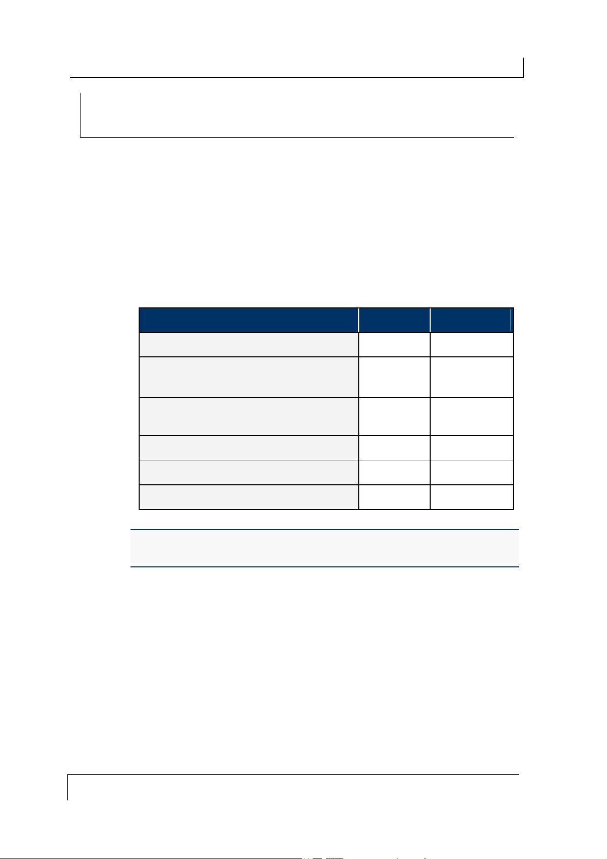
COBALT UHF-SERIES CHAPTER 5: COMMAND PROTOCOLS
CBX SINGLE-TAG RFID COMMAND 0X C2:
READ EPC CODE
COMMAND 0X C2 - D ESCRIPTION
The Read EPC Command instructs the controller to retrieve the EPC memory area
of a single tag UHF Class1 Gen2.
C
OMMAND 0XC2 - CBX E XAMPLE
This example instructs the controller to read the EPC memory from a tag. A Timeout
Value of 2 seconds (0x07D0 = 2000 x one-millisecond increments) is set for the
completion of the command.
Command from Host
PARAMETER FIELD MSB LSB
(in words)
0x00 0x06
0xAA 0xC2
0x00 0x01
0x07 0xD0
0x00 0x00
0x00 0x00
Overall Length of Command
in MSB
0xAA
Command ID
in MSB
0x00
Node ID
Timeout Value
Not Used
Not Used
in LSB (0xC2)
in LSB
(0x00, 0x00)*
(0x00, 0x00)*
*NOTE: even when one or more command parameters are not used in a particular
command, the parameter’s two bytes must still be accounted for in the Overall Length.
Include all “zeroes” for these bytes (0x00, 0x00).
PAGE 76 OF 140

COBALT UHF-SERIES CHAPTER 5: COMMAND PROTOCOLS
Response from Controller (Tag Found)
PARAMETER FIELD MSB LSB
Overall Len gth of Response
in MSB,
0xAA
Instance Counter
Month and Day Timest amp
Hour and Minute Timestamp
Seconds Timestamp
Additional Data Length
(bytes 1 & 2)
EPC
(bytes 3 & 4)
EPC
(bytes 5 & 6)
EPC
(bytes 7 & 8)
EPC
(bytes 9 & 10)
EPC
(bytes 11 & 12)
EPC
Command Echo
in MSB,
in MSB: (:36 seconds)
(in words)
in LSB
Node ID Echo
: (March 19
: (10:11: AM)
in LSB: (0x0C)
in LSB
th
)
0x00 0x0C
0xAA 0xC2
<IC> 0x01
0x03 0x13
0x0A 0x0B
0x24 0x0C
0xE0 0x04
0x01 0x00
0x00 0x2E
0xEB 0x34
0x11 0x35
0x16 0xAD
Response from Controller (Tag Not Found)
PARAMETER FIELD MSB LSB
Overall Len gth of Response
Error Flag
Error Information Byte
0xFF in the LSB indicates that a controller-based
error occurred. Any value other than 0xFF indicates
that a Gateway or Hub-based error occurred (and
identifies the command that was attempted when the
error occurred).
Instance Counter
Month and Day Timest amp
Hour and Minute Timestamp
Seconds Timestamp
Additional Data Length
Error Code
0x00
in MSB = 0xFF
in MSB,
in MSB: (:36 seconds)
in MSB (0x07 = “Tag Not Found”)
in LSB
(in words)
in LSB
Node ID Echo
: (March 19
: (10:11: AM)
in LSB: (0x01)
in LSB
th
)
0x00 0x07
0xFF 0xFF
<IC> 0x01
0x03 0x13
0x0A 0x0B
0x24 0x01
0x07 0x00
PAGE 77 OF 140

COBALT UHF-SERIES CHAPTER 5: COMMAND PROTOCOLS
CBX SINGLE-TAG RFID COMMAND 0X C3:
WRITE EPC CODE
COMMAND 0X C3 - D ESCRIPTION
The Write EPC Command instructs the controller to write the EPC memory area of a
single tag UHF Class1 Gen2.
C
OMMAND 0XC3 - CBX EXAMPLE
This example instructs the controlle r to write the specified bytes in the EPC memory
of a tag. A Timeout Value of 2 seconds (0x07D0 = 2000 x one-millisecond
increments) is set for the completion of the command.
Command from Host
PARAMETER FIELD MSB LSB
Overall Length of Command
in MSB
0xAA
Command ID
in MSB
0x00
Node ID
Timeout Value
EPC Write Data
EPC Write Data
EPC Write Data
EPC Write Data
EPC Write Data
EPC Write Data
in LSB (0x06)
in LSB
(measured in ms)
(bytes 1 and 2)
(bytes 3 and 4)
(bytes 5 and 6)
(bytes 7 and 8)
(bytes 9 and 10)
(byte 11 and 12)
(in words)
0x00 0x0A
0xAA 0xC3
0x00 0x01
0x07 0xD0
0x48 0x45
0x4C 0x4C
0x58 0x45
0xAB 0x6F
0x4E 0x45
0x4F 0x00
PAGE 78 OF 140

COBALT UHF-SERIES CHAPTER 5: COMMAND PROTOCOLS
Response from Controller
PARAMETER FIELD MSB LSB
Overall Len gth of Response
in MSB
0xAA
in LSB
Day
Minute
in LSB
in MSB
Timestamp:
Timestamp:
in MSB
Command Echo
Instance Counter
Node ID Echo
and
Month
(March 19th)
and
Hour
(10:11: AM)
Seconds Timestamp
(:36 seconds)
in LSB
0x00
(in words)
0x00 0x06
0xAA 0xC3
<IC> 0x01
0x03 0x13
0x0A 0x0B
0x24 0x00
PAGE 79 OF 140

COBALT UHF-SERIES CHAPTER 5: COMMAND PROTOCOLS
MULTI-TAG RFID COMMAND 0XC4:
READ EPC CODE
COMMAND 0X C4 - D ESCRIPTION
The Multi-Tag Read EPC Code is used to retrieve the EPC data from all tags within
RF range. A final termination packet is sent when the Timeout Value expires.
C
OMMAND 0XC4 - CBX E XAMPLE
This example instructs the controller to read the EPC data from each tag in range. A
Timeout Value of 3 seconds (0x0BB8 = 3000 x 1msec increments) is set for the
completion of the command.
Command from Host
PARAMETER FIELD MSB LSB
Overall Length of Command
in MSB,
0xAA
in MSB
0x00
Node ID
Timeout Value
Tag Limit
Not Used
in LSB
in MSB,
(0x00, 0x00)*
Response for Each Tag Found
Command ID
0x00
in LSB
in LSB
(in words)
0x00 0x06
0xAA 0xC4
0x00 0x01
0x0B 0xB8
0x64 0x00
0x00 0x00
PARAMETER FIELD MSB LSB
Overall Len gth of Response
in MSB,
0xAA
Instance Counter
Node ID Echo
and
Month
(March 19th)
and
Hour
(10:11: AM)
Command Echo
in MSB
in LSB
Timestamp:
Day
Timestamp:
Minute
(in words)
in LSB
PAGE 80 OF 140
0X00 0X0C
0XAA 0XC4
<IC> 0X01
0x03 0x13
0x0A 0x0B

COBALT UHF-SERIES CHAPTER 5: COMMAND PROTOCOLS
Seconds Timestamp
in MSB
0X24 0X0C
(:36 seconds)
Additional Data Length
additional bytes returned)
EPC ID
EPC ID
EPC ID
EPC ID
EPC ID
EPC ID
(bytes 1 and 2)
(bytes 3 and 4)
(bytes 5 and 6)
(bytes 7 and 8)
(bytes 9 and 10)
(bytes 11 and 12)
in LSB (number of
<ID1> <ID2>
<ID3> <ID4>
<ID5> <ID6>
<ID7> <ID8>
<ID9> <ID10>
<ID11> <ID12>
Final Response Packet
PARAMETER FIELD MSB LSB
Overall Len gth of Response
0xAA
in MSB,
0xFF
in LSB
(in words)
0X00 0X07
0XAA 0XFF
Instance Counter
Node ID Echo
and
Month
in MSB
in LSB
Timestamp:
Day
<IC> 0X01
0x03 0x13
(March 19th)
Hour
and
Minute
Timestamp:
0x0A 0x0B
(10:11: AM)
Seconds Timestamp
in MSB
0X24 0X02
(:36 seconds)
Additional Data Length
“Number of Tags” and “Status”)
Number of Tags Found
in LSB
Status
in LSB (2 bytes:
in MSB
<NUMBER OF
TAGS FOUND>
<0X00 = OPERATION
COMPLETED
SUCCESSFULLY, 0X07
= READ TAG ID FAILED
/ TAG NOT FOUND>
PAGE 81 OF 140

COBALT UHF-SERIES CHAPTER 5: COMMAND PROTOCOLS
CONTROLLER SPECIFIC COMMAND 0X C0:
SET UHF CONFIGURATION
COMMAND 0X C0 – D ESCRIPTION
The Set UHF Configuration command is used to set (configure or modify) the
controller’s UHF configuration parameters and settings to the controller’s flash
memory.
IMPORTANT: it is recommended that users first run Command 0xC1: Get UHF
Configuration and make note of their current controller configuration values prior to
executing this command.
OMMAND 0XC0 - CBX E XAMPLE
C
This example permits the user to modify or write the indicated configuration settings
to the controller’s flash memory. The total number of bytes available for this purpose
is nine.
Command from Host
PARAMETER FIELD MSB LSB
in LSB
in MSB
in LSB
in LSB
in LSB
(in words)
Reader Output Power
in MSB
in MSB
0x00 0x08
0xAA 0xC0
0x00 0x01
<Byte 1> <Byte 2>
<Reserved> * <Reserved> *
<Reserved> * <Reserved> *
Overall Length of Command
in MSB
0xAA
Command ID
in MSB,
0x00
UHF Configuration Byte 1
UHF Configuration Byte 2
These two-bytes represent the
(value from 0 to 500 mW).
UHF Configuration Byte 3
UHF Configuration Byte 4
UHF Configuration Byte 5
UHF Configuration Byte 6
in LSB: (0x43)
Node ID
PAGE 82 OF 140
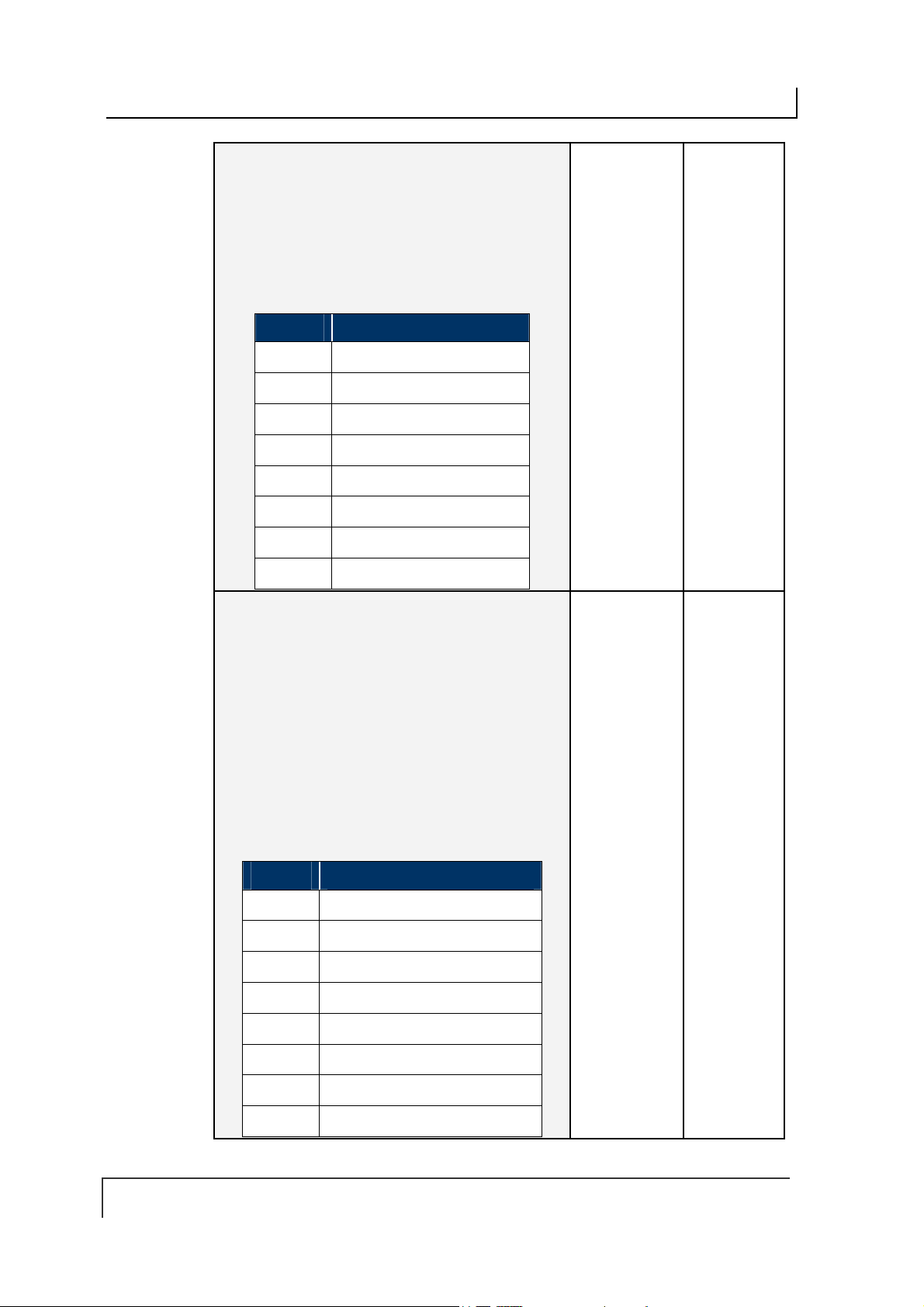
COBALT UHF-SERIES CHAPTER 5: COMMAND PROTOCOLS
in MSB
in LSB
in MSB
disabled
enabled
UHF channel
Choose
, an error
, the
UHF Configuration Byte 7
UHF Configuration Byte 8
Byte 8 in LSB is partially reserved (see table below). This
byte permits the user to select the specific
through which commands are transmitted. The user can
write a value between o and 9 in bits from 4 to 7
UHF Config. Byte 8 - Table
BIT Description
0
1
2
3
4
5
6
7
UHF Configuration Byte 9
in LSB (not used)
0x00
Byte 9 in MSB is partially reserved (see table below).This
byte permits the user to enable/disable the
Nearest One
If the Choose Nearest One property is
response is generated whenever a single-tag read/write
command is executed in a multi-tag environment.
If the Choose Nearest One property is
read/write command is executed on the tag with the
strongest signal.
Reserved*
Reserved*
Reserved*
Reserved*
<Channel ID value>
<Channel ID value>
<Channel ID value>
<Channel ID value>
property.
UHF Config. Byte 9 - Table
<Reserved> *
<Partially
Reserved>
<Partially
Reserved>
0x00
BIT Description
0
1
2
3
4
5
6
7
Reserved*
<Choose Nearest One option>
Reserved*
Reserved*
Reserved*
Reserved*
Reserved*
Reserved*
PAGE 83 OF 140

COBALT UHF-SERIES CHAPTER 5: COMMAND PROTOCOLS
*Leave the default value retrieved through Command 0xC1: Get UHF Configuration
Response from Controller
PARAMETER FIELD MSB LSB
Overall Len gth of Response
in MSB
0xAA
in LSB
Day
Minute
in LSB
in MSB
Timestamp:
Timestamp:
in MSB
Command Echo
Instance Counter
Node ID Echo
and
Month
(March 19th)
and
Hour
(10:11: AM)
Seconds Timestamp
(:36 seconds)
in LSB
0x00
(in words)
0x00 0x06
0xAA 0xC0
<IC> 0x01
0x03 0x13
0x0A 0x0B
0x24 0x00
PAGE 84 OF 140
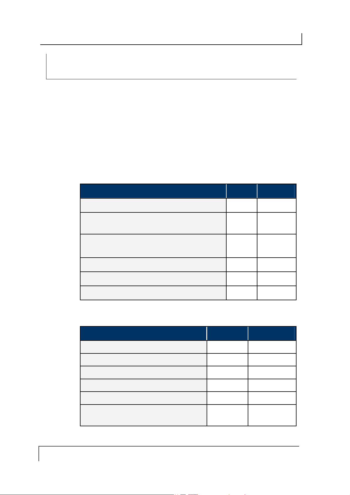
COBALT UHF-SERIES CHAPTER 5: COMMAND PROTOCOLS
CONTROLLER SPECIFIC COMMAND 0X C1:
GET UHF CONFIGURATION
COMMAND 0X C1 – D ESCRIPTION
The Get UHF Configuration Command instructs the controller to retrieve the
controller’s UHF configuration parameters and settings stored in the unit’s flash
memory. These are the same values that are set with Command 0xC0: Set UHF
Configuration.
C
OMMAND 0XC1 - CBX E XAMPLE
Through this command, the user queries a Cobalt UHF RFID controller and reads the
controller’s UHF configuration data from its flash memory.
Command from Host
PARAMETER FIELD MSB LSB
Overall Length of Command
in MSB
0xAA
Command ID
in MSB
0x00
Node ID
Not Used
Not Used
Not Used
in LSB
in LSB
(default: 0x00, 0x00)
(default: 0x00, 0x00)
(default: 0x00, 0x00)
(in words)
0x00 0x06
0xAA 0xC1
0x00 0x01
0x00 0x00
0x00 0x00
0x00 0x00
Response from Controller
PARAMETER FIELD MSB LSB
Overall Len gth of Response
in MSB,
0xAA
Instance Counter
Command Echo
in MSB,
(in words)
in LSB
Node ID Echo
in LSB
0x00 0x0B
0xAA 0xC1
<IC> 0x01
Month and Day Timest amp
Hour and Minute Timestamp
Seconds Timestamp
Additional Data Length
in MSB: (:36 seconds)
in LSB: (0x0A)
: (March 19
: (10:11: AM)
PAGE 85 OF 140
th
)
0x03 0x13
0x0A 0x0B
0x24 0x0A
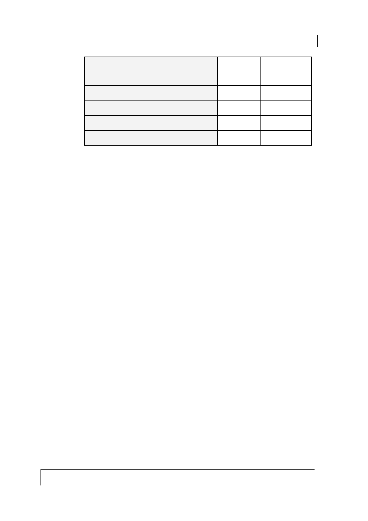
COBALT UHF-SERIES CHAPTER 5: COMMAND PROTOCOLS
UHF Configuration Bytes 1 & 2
These two bytes represent the
(0÷500 mW).
Power
UHF Configuration Bytes 3 & 4
UHF Configuration Bytes 5 & 6
UHF Configuration Bytes 7 & 8
UHF Configuration Bytes 9 & 10
Reader Output
<Byte 1> <Byte 2>
<Byte 3> <Byte 4>
<Byte 5> <Byte 6>
<Byte 7> <Byte 8>
<Byte 9> 0x00
PAGE 86 OF 140

COBALT UHF-SERIES CHAPTER 5: COMMAND PROTOCOLS
5.6 ERROR CODE TABLE
ERROR
CODE
0x04
0x05
0x06
0x07
0x21
0x30
0x31
0x32
0x35
0x36
ERROR DESCRIPTION
FILL TAG FAILED Fill Tag operation failed
READ DATA FAILED Read Data operation failed
WRITE DATA FAILED Write Data operation failed
TAG NOT FOUND, TAG SEARCH
FAILED
INVALID SYNTAX Command Co ntained a synta x error
INTERNAL CONTROLLER
ERROR
INVALID CONTROLLER TYPE Invalid controller type (when setting
INVALID PROGRAMMING
ADDRESS
INVALID RESET Invalid hardware reset
SET CONFIGURATION ERROR
Read Tag ID operation failed, Tag
Search operation failed
Generic internal controller error
configuration)
Invalid tag programming address
specified
Configuration not written
0x37
0x83
0x84
0x85
0x86
0x87
0x88
GET CONFIGURATION ERROR
COMMAND INVALID OPCODE Invalid Command ID specified in the
COMMAND INVALID
PARAMETER
COMMAND INVALID
CONTROLLER ID
COMMAND INACTIVE
CONTROLLER ID
SUBNET DEVICE SELECT
FAILED
SUBNET DEVICE FAILED TO
ACKNOWLEDGE
Configuration not read
command.
A parameter specified in the command
was invalid.
An invalid Node ID was specified in the
command, or no controller was
detected/present at the specified Node.
The Node ID specified in the command
is currently inactive.
Internal Subnet Error – the specified
Subnet device failed.
Internal Subnet Error - the specified
Subnet device failed to respond to the
Cobalt’s polling.
PAGE 87 OF 140

COBALT UHF-SERIES CHAPTER 5: COMMAND PROTOCOLS
0x89
0x8A
0x8B
0x8C
0x8D
0x8E
0x92
0x93
SUBNET RESPONSE
MALFORMED
SUBNET RESPONSE TIMEOUT Internal Subnet Error – a controller was
SUBNET RESPONSE INVALID
CHECKSUM
SUBNET DEVICE CONFLICT
DETECTED
BUFFER OVERFLOW Internal Error – buffer limit was
FLASH FAILURE Internal Error – flash memory failure
SUBNET16 ONLY COMMAND A Subnet16-only command was issued
NODE MISMATCH ERROR The Node specified in the command
Internal Subnet Error – a controller
returned a malformed response.
unable to generate a response before
timeout was reached.
Internal Subnet Error – a controller
generated a response that has an
invalid checksum.
Internal Subnet Error – a Node ID
conflict has been detected
exceeded
when in MUX32 mode.
did not match the Node to which the
command was sent
0x94
0x95
CRC ERROR Internal Communications Error
PROTOCOL ERROR Internal Communications Error
Table 5-19: Error Code Table
PAGE 88 OF 140
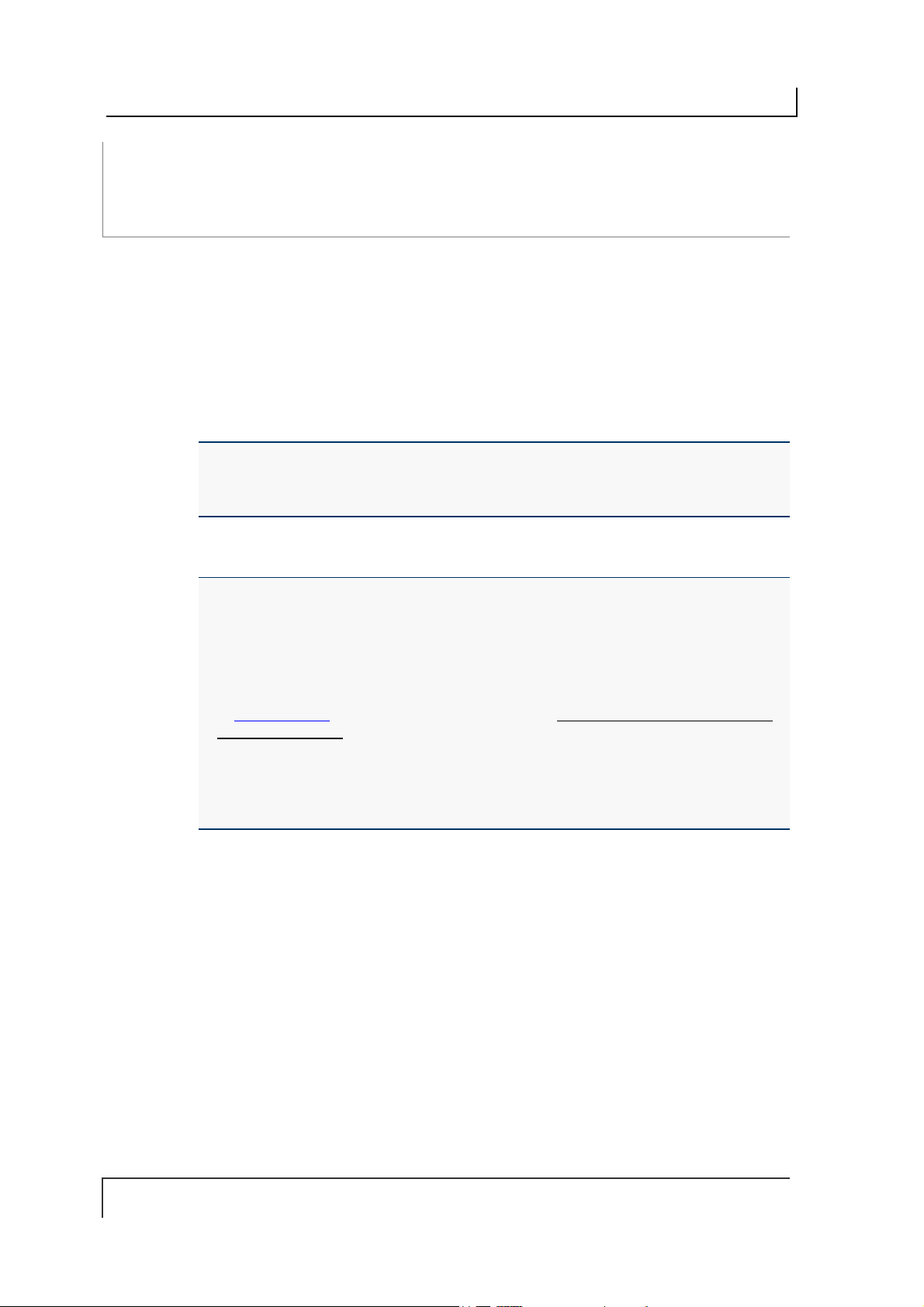
COBALT UHF-SERIES CHAPTER 6: ETHERNET/IP INTERFACE
CHAPTER 6:
ETHERNET/IP INTERFACE
The Cobalt UHF-CNTL-IND-02 model is designed to support many common
Industrial Ethernet protocols and can be implemented in a wide variety of existing
host / PLC applications. One such popular Ethernet protocol is Ethernet/IP (EIP).
This chapter focuses on the process of setting up the Cobalt Industrial RFID
Controller to communicate (via Ethernet/IP) with a ControlLogix Programmable Logic
Controller (PLC).
Also in this chapter are descriptions of EMS’ HTML Server and OnDemand Utilities,
as well as systematic instructio ns to help configure the Cobalt Industrial RFID
Controller for Ethernet/IP environments.
NOTE: This manual assumes that users are already familiar with Ethernet/IP, industrial
Ethernet communications protocols and programmable logic controller technologies.
For specific information regarding the protocol used by your particular RFID application,
please refer to the appropriate documentation from your host / PLC program provider.
IMPORTANT:
Users of the Cobalt Dashboard utility should exit the application before attempting
communications between the Industrial Cobalt and an EtherNet/IP host
Programmable Logic Controller (PLC).
When installing the UHF-CNTL-IND-02 for communication over EtherNet/IP, the
ODVA Guidelines for EtherNet/IP Media System installation should be followed (refer
to www.odva.org, ODVA PUB00148R0 (Pub 148), EtherNet/IP Media Planning and
Installation Manual, 2006 ODVA).
Follow ODVA recommendations for switching and wiring Ethernet/IP.
If the Ethernet/IP network enables I/O Messaging for re mote I/O, etc., or if other UDP
traffic is present, then the Gateway must be protected by a switch that incorporates
IGMP Snooping or a VLAN.
6.1 ETHERNET/IP CONFIGURATION OVERVIEW
Based upon on the standard TCP/IP protocol suite, EtherNet/IP is a high-level
application layer protocol for industrial automation applications that uses traditional
Ethernet hardware and software to define an application layer protocol that structures
the task of configuring, accessing and controlling industrial automation devices.
Ethernet/IP classifies Ethernet nodes as predefined device types with specific
behaviors. The set of device types and the EIP application layer protocol is based on
the Common Industrial Protoc ol (CI P ) laye r use d in Co ntrolN et . Bu ilding on these two
widely used protocol suites, Ethernet/IP provides a seamlessly integrated system
from the RFID Subnet network to the Host and enterprise networks.
The Cobalt is designed to communicate as an EtherNet/IP client device, which will
receive and execute RFID commands issued by the host / PLC (acting as
EtherNet/IP Server).
PAGE 89 OF 140

COBALT UHF-SERIES CHAPTER 6: ETHERNET/IP INTERFACE
Sections 6.3 through 6.7 contain instructions that will help you accomplish the
following:
Assign the Cobalt an IP address via HTML Server
Configure the Cobalt’s Subnet Node via OnDemand Utilities
Create “Controller Tags” in the PLC
Verify PLC and Cobalt Subnet Node connectivity
6.2 HTML SERVER & ONDEMAND PLC SUPPORT
Below is a partial list of the programmable logic controllers that are supported by
EMS’ HTML Server and OnDemand Utilities.
ControlLogix – OnDemand supports all current versions
RA’s PLC5E releases:
Series C, Revision N.1
Series D, Revision E.1
Series E, Revision D.1
PLC5 "Sidecar" Module Series B, Revision A with EIP support
SLC5/05 releases:
Series A with firmware revision OS501, FRN5
All Series B and Series C PLC Controllers
6.3 HTML SERVER AND ONDEMAND UTILITIES
Embedded in the Cobalt UHF-CNTL-IND-02 is an HTML Server, which provides a
Website-like interface and a suite of configuration tools.
Through the use of the Cobalt’s HTML Server, users can access, modify and save
changes to the unit’s Industrial Ethernet configuration, IP address, and OnDemand
mode settings.
The OnDemand Utilities will be used later in this chapter to link the Cobalt to specific
Controller Tags as defined in Rockwell Automation’s (RA) ControlLogix PLC.
ATTENTION: Disable any firewall services affecting or running locally on the host
computer. Firewalls can potentially block comm unic atio ns between the Cobalt and the
host and/or PLC.
ADDITIONAL INFORMATION: In ControlLogix, a “Controller Tag” is a small block of
internal memory that is used to hold outgoing (command) and incoming (response)
data. Within each controller tag, information is stored in two-byte segments, known as
registers or “words.”
OnDemand is Escort Memory Systems’ approach to adding Change of State
messaging to ControlLogix and legacy support for RA PLC5E and RA SCL5/05
programmable logic controllers.
PAGE 90 OF 140
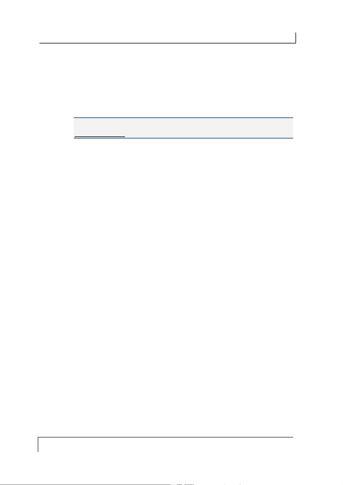
COBALT UHF-SERIES CHAPTER 6: ETHERNET/IP INTERFACE
6.4 IP CONFIGURATION VIA
To configure the Cobalt for Ethernet communications, begin by assigning the
controller a locally compatible IP address.
Through a standard Web browser, you can utilize the Cobalt’s HTML Server to
access an embedded suite of controller configuration tools, called the “OnDemand
Utilities.” Among its features is the ability to modify and save changes to the
controller’s IP address, which is stored internally on the Cobalt.
Cobalt Industrial Ethernet RFID Controller - Default IP Address:
192.168.253.110
SETTING THE IP ADDRESS OF THE COBALT
To set the Cobalt’s IP address using the HTML Server, follow the steps below:
Open a Web browser on the PC.
1.
In the URL address field, enter the Cobalt’s IP address (192.168.253.110 =
2.
factory default).
HTML
Press
3.
SERVER – M AIN P AGE
ENTER
The HTML Server - Main Page will be displayed.
.
HTML S
ERVER
Figure 6-1: The HTML Server - Main Page
The HTML Server - Main Page lists the IP address and network settings currently
stored on the Cobalt.
PAGE 91 OF 140

COBALT UHF-SERIES CHAPTER 6: ETHERNET/IP INTERFACE
Click the button labeled “
4.
The IP Configuration Page will be displayed.
CONFIGURATION P AGE
IP
The IP Configuration Page is used to modify and save changes to the IP Address,
Subnet Mask and (Network) Gateway IP Address.
”, located below “
EDIT
Network Settings.
”
Figure 6-2: The IP Configuration Page
In the fields provided, enter your new IP configuration values for the Cobalt.
5.
Click the
6.
cycle power to the UHF-CNTL to store the changes in the main memory. The
Ethernet module will reset and your IP changes will be implemented.
After the Cobalt has restarted, verify the new IP configuration by opening a
7.
Web browser and manually entering the Cobalt’s new IP address in the URL
field. If successful, you should arrive back at the HTML Server – Main Page.
Save Settings
“
” button to store your new IP configuration, then
PAGE 92 OF 140

COBALT UHF-SERIES CHAPTER 6: ETHERNET/IP INTERFACE
6.5 ONDEMAND CONFIGURATION FOR ETHERNET/IP
Now that you have configured the Cobalt’s IP address, you will need to use the
embedded HTML Server to access the Cobalt’s OnDemand Configuration Page.
Through the use of the OnDemand Configuration Page, the Cobalt can be configured
to communicate with a ControlLogix PLC.
To configure the Cobalt’s OnDemand Configuration settings, follow the steps below:
Open a Web browser on the host and enter the Cobalt’s new IP address in the
1.
URL field. The HTML Server – Main Page will be displayed.
At the HTML Server – Main Page, click the button labeled “
2.
OnDemand Config
.”
The OnDemand Configuration Page will be displayed.
PAGE 93 OF 140
COBALT UHF-SERIES CHAPTER 6: ETHERNET/IP INTERFACE
ON DEMAND C ONFIGURATION PAGE
The OnDemand Configuration Page allows you to modify the settings of the
Cobalt’s Node.
Figure 6-3: The OnDemand Configuration Page
In the upper portion of the OnDemand Configuration Page, select a
3.
from the drop-down menu.
Enter the PLC’s IP address.
4.
For the
5.
Number indicates the location in your PLC rack where the controller module is
installed (normally slot 0 for ControlLogix).
PLC Slot Number,
enter a value between 0 and 255. The PLC Slot
PLC Type
PAGE 94 OF 140

COBALT UHF-SERIES CHAPTER 6: ETHERNET/IP INTERFACE
In the
6.
7.
8. Write Size:
9. Write Tag Name:
OR
Write Tag Name: For PLC5E, SLC5/05 and MicroLogix systems, enter the PCCC
File Number and Offset (for example N7:0) in the Write Tag Name field. Together
these values identify the location in the PLC’s Status File where host-bound data will
be written for the Cobalt.
10. Read Size:
11. Read Tag Name:
Read Delay
specifies (in 10ms “ticks”) how frequently the Cobalt will poll the PLC for the
presence of new data. (Note: a value of 6000 = 60 seconds; zero = disable).
In the column labeled “
Other Nodes listed on this page are not supported by the Cobalt –IND.
The Write Size represents the maximum number of 2-byte “words” that the
Cobalt will attempt to write to PLC memory during a single write cycle. (Note: to
accommodate message handshaking overhead, the actual data size required by
the PLC is three words larger than the value specified in this field).
40 characters or less (for example EMS_WRITE1, for Node 01). The Write Tag
Name is a user defined description or title for the area of memory in the PLC
where host-bound data will be written for the Cobalt. (Note: the Write Tag Name
is not to be confused with writing to an RFID transponder, which is often referred
to as “writing to a tag”).
Enter a value between 1 and 100 (or 0 to disable) for the
The Read Size represents the maximum number of 2-byte “words” that the
Cobalt will attempt to retrieve from PLC memory during a single read cycle.
(Note: to accommodate message handshaking overhead, the actual data size
required by the PLC is three words larger than the value specified in this field).
40 characters or less (for example EMS_READ1, for Node 01). The Read Tag
Name is a user defined description or title for the area of memory in the PLC
from which the Cobalt will retrieve data.
field, enter a value between 0 and 6000. This number
Enable Node,
Enter a value between 1 and 100 (or 0 to disable) for the
For ControlLogix systems, specify a
For ControlLogix systems, specify a
” place a check in the box for
Write Tag Name
Read Tag Name
Node 01.
Write Size.
that is
Read Size.
that is
OR
Read Tag Name: For PLC5E, SLC5/05 and MicroLogix systems enter the
PCCC File Number and Offset in the Read Tag Name field. Together these
values indicate the location in the PLC’s Status File from which the Cobalt
will retrieve data.
After entering the proper information for Node 01, click the
12.
located at the bottom of the page.
The OnDemand Status Page will be displayed.
PAGE 95 OF 140
Save Settings
button

COBALT UHF-SERIES CHAPTER 6: ETHERNET/IP INTERFACE
At the OnDemand Status Page, click the link labeled “
13.
HTML Server – Main Page.
Main Page
6.6 CONFIGURING PLC CONTROLLER TAGS
After you have configured the Cobalt’s Node via the OnDemand Configuration Page,
open your PLC program (i.e. RSLogix 5000) and, if you have not already done so,
define two Controller Tags (a Write Tag and a Read Tag).
Controller Tag Naming
Controller Tags need to be assigned a name and size. Be sure to use the same
Write Tag Name and Read Tag Name that you specified in the OnDemand Node
Configuration (i.e., EMS_WRITE1 and EMS_READ1).
” to return to the
Controller Tag Size
Due to handshaking overhead, Controller Tags must have the size capacity to store
an integer array equal to your previously specified Write/Read Size + three words.
So for example, if the Read Size you specified earlier was 100 words, the
corresponding Read Tag in the PLC must be able to store an array of 103 integers.
The Write Tag holds messages and response data generated by the Cobalt that
is bound for the host or PLC.
The Read Tag holds RFID commands and instructions intended for the Cobalt.
(NOTE: the Cobalt should already be linked to the proper Write Tag and Read Tag
via the OnDemand Utilities - OnDemand Configuration Page).
After creating and defining a Write Tag and a Read Tag for the Cobalt, return to the
Cobalt’s HTML Server – Main Page to continue.
PAGE 96 OF 140
COBALT UHF-SERIES CHAPTER 6: ETHERNET/IP INTERFACE
6.7 CHECKING ONDEMAND STATUS
Now that you have configured the Cobalt’s Node and defined corresponding Write
and Read Tags in the PLC, the last step is to check the communication status
between the Cobalt and the PLC.
Return to the Cobalt’s HTML Server - Main Page and click the link labeled
“OnDemand Status.” The OnDemand Status Page will be displayed.
Figure 6-4: The OnDemand Status Page
The OnDemand Status Page provides statistical information regarding the connection
status of the Cobalt. This information can be used to verify that read and write
connections between the Cobalt and the PLC have been established successfully.
Read Counts: this value indicates the number of times the Cobalt has checked
the PLC for new data.
Write Counts: this value indicates the number of times the Cobalt has provided
data to the PLC.
Note that under Ethernet/IP, the host (and/or PLC) acts as the server. However,
additional messaging instructions are not required on the part of the host because
the Cobalt will automatically poll the Read Tag in the PLC at the interval specified by
the Read Delay value set via the OnDemand Configuration Utility.
There is no delay parameter when writing data to the PLC, as the Cobalt delivers all
PLC-bound data immediately after it is generated.
If you configured a low Read Delay value, the Read Counts on the OnDemand
Status Page will accumulate rapidly. This occurs because a low Read Delay value
instructs the Cobalt to poll the PLC for new data more frequently.
ATTENTION:
If the Cobalt and PLC do not successfully establish a connection, cycle power to the
Cobalt and verify that Ethernet/IP services are running properly on the PLC. If that does
not resolve the issue, restart Ethernet/IP services on the PLC and the 1756-ENBT
module.
PAGE 97 OF 140
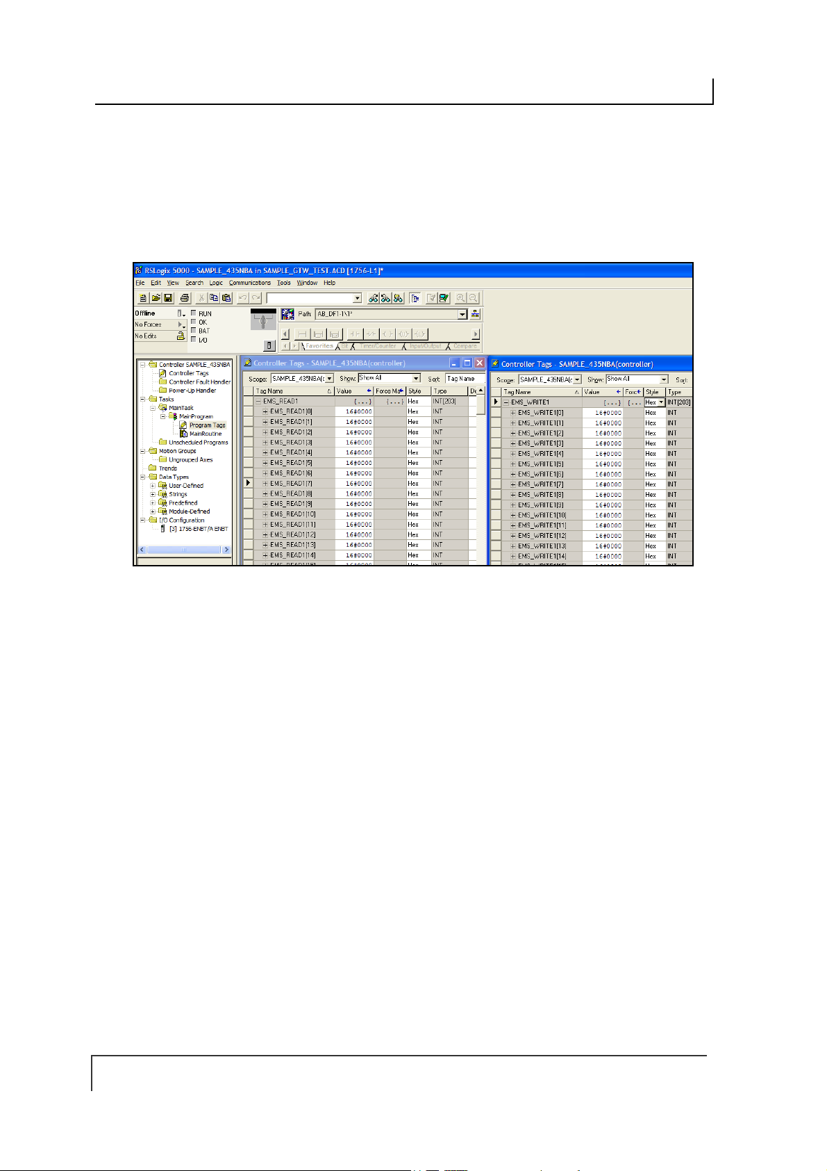
COBALT UHF-SERIES CHAPTER 6: ETHERNET/IP INTERFACE
6.8 VERIFYING DATA EXCHANGE WITH
OGIX 5000
RSL
At this point, communication between the Cobalt and the PLC should be properly
configured and a connection establish ed . You ca n verify the exc ha nge of inf ormat io n
between devices using RSLogix 5000.
Figure 6-5: R SLogix 5000
6.8.1 Ethernet/IP Handshaking
To ensure that messages to and from the Cobalt are properly delivered and received,
a handshaking mechanism has been implemented that uses a pair of dedicated
words in the exchange. The first two words in each Controller Tag are dedicated to
handshaking.
When new information is generated, the producing device (Data Producer) will
increment a counter in one of the Controller Tags. After identifying the new data, the
consuming device (Data Consumer) will copy that same counter value to a different
Controller Tag location, which lets the Data Producer know that the information has
been processed by the Data Consumer.
PAGE 98 OF 140

COBALT UHF-SERIES CHAPTER 6: ETHERNET/IP INTERFACE
WRITE TAG (where responses are written by the Cobalt)
EMS_Write1 [0] = (2) the Cobalt copies counter here to ACK
EMS_Write1 [1] = (3) the Cobalt increments this counter to signal response available
EMS_Write1 [2] = Data Size
EMS_Write1 [3-102] = Data
READ TAG (where commands are retrieved by the Cobalt)
EMS_Read1 [0] = (4) PLC copies the counter here to ACK the response
EMS_Read1 [1] = (1) PLC increments this counter after writing a command
EMS_Read1 [2] = Data Size
EMS_Read1 [3-102] = Data
6.8.2 Ethernet/IP Handshaking Example
In the example below, EMS_READ1 is the name of the Read Tag and EMS_WRITE1
is the name of the Write Tag.
NOTE: [0] indicates the first word, [1] indicates the second word in a controller tag.
The PLC writes the command to the Read Tag (EMS_READ1) and then
1.
increments the counter in EMS_READ1 [1]
The counter in EMS_READ1 [1] is copied by the Cobalt to EMS_WRITE1 [0]
2.
which acknowledges that the command has been received.
Following execution of the command, the Cobalt copies the response to
3.
EMS_WRITE1 (the Write Tag) and increments the counter in EMS_WRITE1 [1].
This signals that there is new data for the PLC (the Cobalt generated response,
in this case).
PAGE 99 OF 140
COBALT UHF-SERIES CHAPTER 6: ETHERNET/IP INTERFACE
After the PLC has processed the response information, it copies the counter from
4.
EMS_WRITE1 [1] to EMS_READ1 [0] which signals to the Cobalt that the PLC
has retrieved the response data.
The data will then be cleared from EMS_WRITE1. After which the Cobalt will be
5.
ready to receive another command.
6.9 ETHERNET/IP: OBJECT MODEL
The Object Model is the logical organization of attributes (parameters) within classes
(objects) and services supp orte d by ea c h dev ice.
Objects are broken down into three categories: Required Objects, Vendor Specific
Objects and Application Objects.
Required Objects are classes that must be supported by all devices on
EtherNet/IP. The Cobalt has six Required Objects.
Vendor Specific Objects are classes that add attributes and services that
do not fit into the Required Objects or Application Objects categories. The
Cobalt has two Vendor Specific Objects.
Application Objects are classes that must be supported by all dev ic es usin g
the same profile. An example of a profile is a Discrete I/O device or an AC
PAGE 100 OF 140
 Loading...