

Balluff M56HSAREI0100 Users Manual

HS500E
READ/WRITE INDUSTRIAL ETHERNET ANTENNA
Escort Memory Systems’ Active Radio Frequency Identification Device
PERATOR’S MANUAL
O
How to Install, Configure and Operate
Escort Memory Systems’
HS500E Industrial Ethernet Antenna
HS500E Industrial Ethernet Antenna - Operator’s Manual - P/N: 17-1305 REV 01.D (08-05)

FCC COMPLIANCE NOTICE
FCC Part 15
This equipment has been tested and found to comply with the limits for a Class A
digital device, pursuant to part 15 of the FCC Rules. These limits are designed to
provide reasonable protection against harmful interference in a residential installation.
This equipment uses, generates, and can radiate radio frequency energy and, if not
installed and used in accordance with these instructions, may cause harmful
interference to radio communications. However, there is no guarantee that
interference will not occur in a particular installation. If this equipment does cause
harmful interference to radio or television reception, which can be determined by
turning the equipment off and on, the user is encouraged to try to correct the
interference by one or more of the following measures:
Reorient or relocate the receiving antenna.
Increase the separation between the equipment and receiver.
Connect the equipment into an outlet on a circuit different from that to which
the receiver is connected.
Consult the dealer or an experienced radio/TV technician for help.
Users are cautioned that changes or modifications to the unit not expressly approved
by Escort Memory Systems may void the user’s authority to operate the equipment.
This device complies with Part 15 of the FCC Rules. Operation is subject to the
following two conditions: (1) this device may not cause harmful interference, and (2)
this device must accept any interference that may cause undesired operation.
This product complies with CFR Title 21 Part 15.

TABLE OF CONTENTS
TABLE OF CONTENTS
TABLE OF CONTENTS.............................................................................................4
CHAPTER 1: GETTING STARTED...........................................................................6
1.1 Introduction.............................................................................................................6
Company Background................................................................................................................. 6
RFID Overview ............................................................................................................................ 6
1.2 About this Manual...................................................................................................7
Who Should Read this Manual?.................................................................................................. 7
HEX Notation............................................................................................................................... 7
1.3 HS500E Dimensions & Diagrams..........................................................................8
CHAPTER 2: INTERFACING WITH THE HS500E..................................................11
2.1 MODBUS-TCP Interface........................................................................................12
2.2 Ethernet/IP Interface.............................................................................................14
2.3 TCP/IP Interface ....................................................................................................18
2.4 OnDemand Configuration....................................................................................21
2.4.1 IP Configuration............................................................................................................. 22
2.4.2 OnDemand Configuration ............................................................................................. 23
2.4.3 Configuring the PLC...................................................................................................... 26
2.5 Checking Communication Status........................................................................27
2.5.1 Checking the OnDemand Status Page......................................................................... 27
2.6 VERIFYING THE EXCHANGE OF DATA VIA RSLOGIX 5000.............................28
2.6.1 Handshaking ................................................................................................................. 29
2.6.2 Handshaking Example .................................................................................................. 29
CHAPTER 3: RFID COMMANDS............................................................................32
3.1 Command Structure .............................................................................................32
RFID Command Packet Structure............................................................................................. 32
3.2 RFID Commands...................................................................................................33
RFID Commands Table.............................................................................................................33
Command 02: Read Data...............................................................................................34
Command 03: Write Data...............................................................................................36
Command 05: Fill Tag....................................................................................................38
Command F0: Read HS500E Information ....................................................................40
Command F1: Test LEDs / Read HS500E Information................................................42
Command F2: Start/Stop Repetitive Command ..........................................................44
HS500E – OPERATOR’S MANUAL P/N: 17-1305 REV 01.D (08-05)
PAGE 4 OF 51

TABLE OF CONTENTS
Command F3: Write IP Address....................................................................................46
Command F4: Reset Battery Counter Value................................................................47
CHAPTER 4: ERROR CODES................................................................................48
Basic Error Types...........................................................................................................48
Overall Length Errors................................................................................................................. 48
Length Limits ............................................................................................................................. 48
Write Length Limit...................................................................................................................... 48
Timeout Fail Code ..................................................................................................................... 48
APPENDIX A: ASCII CHART..................................................................................49
EMS WARRANTY....................................................................................................51
HS500E – OPERATOR’S MANUAL P/N: 17-1305 REV 01.D (08-05)
PAGE 5 OF 51

CHAPTER 1: GETTING STARTED
CHAPTER 1: GETTING STAR TED
This chapter contains an introduction to Escort Memory Systems and includes
general information relating to the HS500E Industrial Ethernet Antenna and common
uses for RFID technology.
1.1 INTRODUCTION
Welcome to the HS500E Industrial Ethernet Antenna - Operator’s Manual. This
manual will assist you in the installation, configuration and operation of Escort
Memory Systems’ HS500E Industrial Ethernet Antenna.
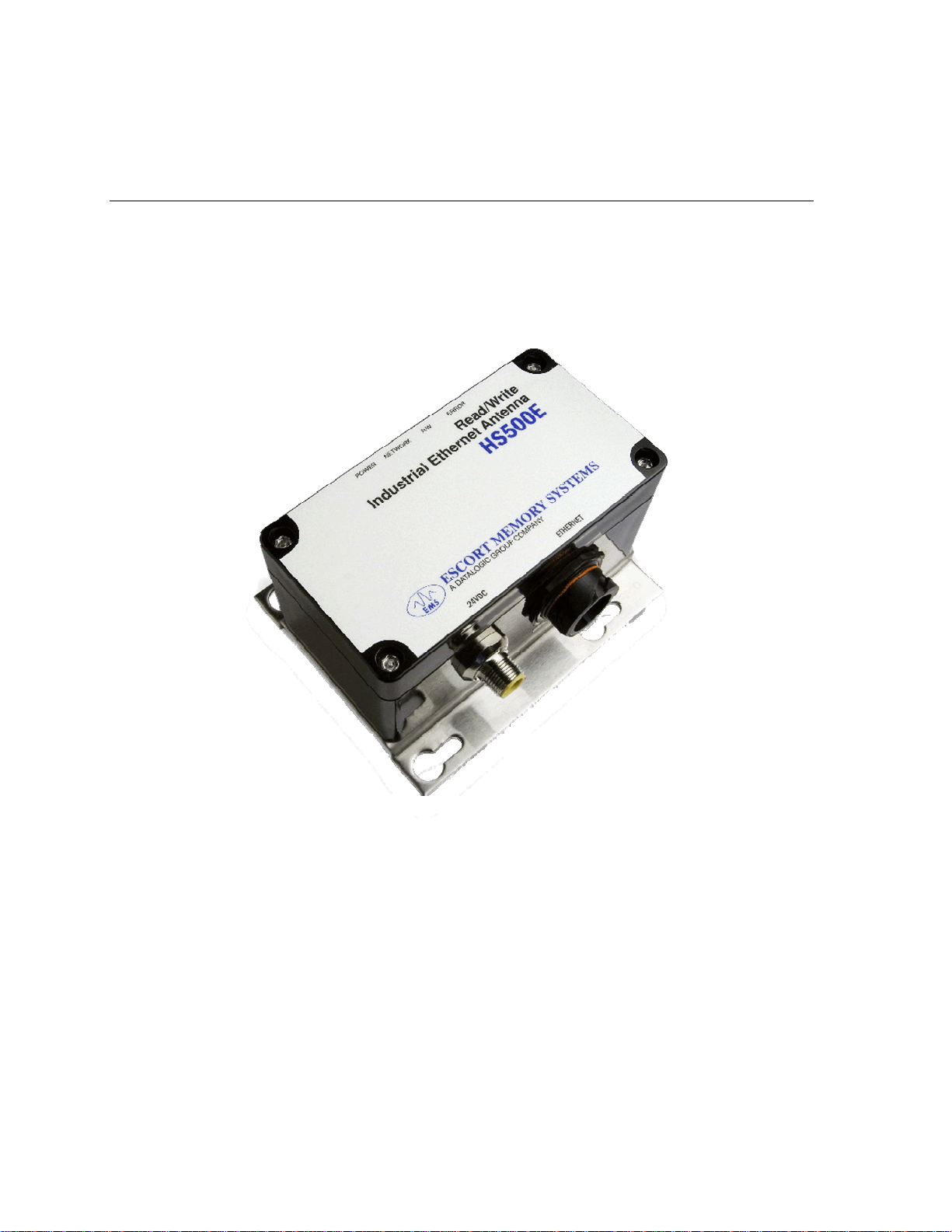
The HS500E Ethernet
Antenna is a complete
read/write RadioFrequency Identification
solution. It is designed
to be reliable and
rugged, in order to meet
and exceed the
requirements of the
industrial automation
industry. The HS500E
Ethernet Antenna
provides RFID data
collection and control
solutions to shop floor,
item-level tracking and
material handling
applications.
Company Background
Escort Memory Systems’ headquarters in
Scotts Valley, CA.
Escort Memory Systems has long been an industry leader in providing Radio
Frequency Identification (RFID) devices, building a solid reputation by consistently
delivering an extended selection of quality, durable industrial RFID systems.
RFID Overview
The first step in most RFID systems involves attaching a tag to a product or its carrier.
The RFID tag acts as an electronic identifier, portable job sheet, or real-time tracking
database. Tags are identified, read and written to by issuing specific commands from
a Host computer. Tags can be read and written to through any nonconductive, nonmetallic material, while moving or standing still, in or out of the direct line of sight.
HS500E – OPERATOR’S MANUAL P/N: 17-1305 REV 01.D (08-05)
PAGE 6 OF 51

CHAPTER 1: GETTING STARTED
1.2 ABOUT THIS MANUAL
This document provides guidelines and instructions on how to install and operate the
HS500E Industrial Ethernet Antenna. Also included are descriptions of the RFID
command set with instructions detailing how to issue commands from the Host
computer to the HS50
Who Should Read this Manual?
Those who will be installing, configuring and operating the HS500E should re ad this
manual. This may include the following people:
• Hardware Installers
0E.
SIDE NOTE:
Occasionally throughout this manual, we refer to the HS500E
Industrial Ethernet Antenna as the HS500E, the HS500E
Antenna, the Industrial Antenna or just simply “the Antenna.”
• System Integrators
• Project Managers
• IT Personnel
• System and Database Administrators
• Software Application Engineers
• Service and Maintenance Engineers
HEX Notation
In this manual, numbers expressed in Hexadecimal notation are prefaced with “0x”.
For example, the number "10" in decimal is expressed as "0x0A" in hexadecimal.
Appendix A for a chart containing Hex values, ASCII characters and their
See
corresponding decimal integers.
HS500E – OPERATOR’S MANUAL P/N: 17-1305 REV 01.D (08-05)
PAGE 7 OF 51
CHAPTER 1: GETTING STARTED
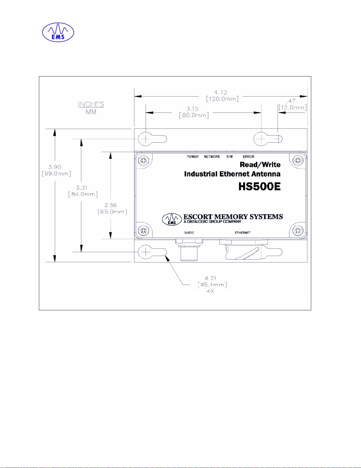
1.3 HS500E DIMENSIONS & DIAGRAMS
HS500E - Dimensions
HS500E – OPERATOR’S MANUAL P/N: 17-1305 REV 01.D (08-05)
PAGE 8 OF 51
CHAPTER 1: GETTING STARTED
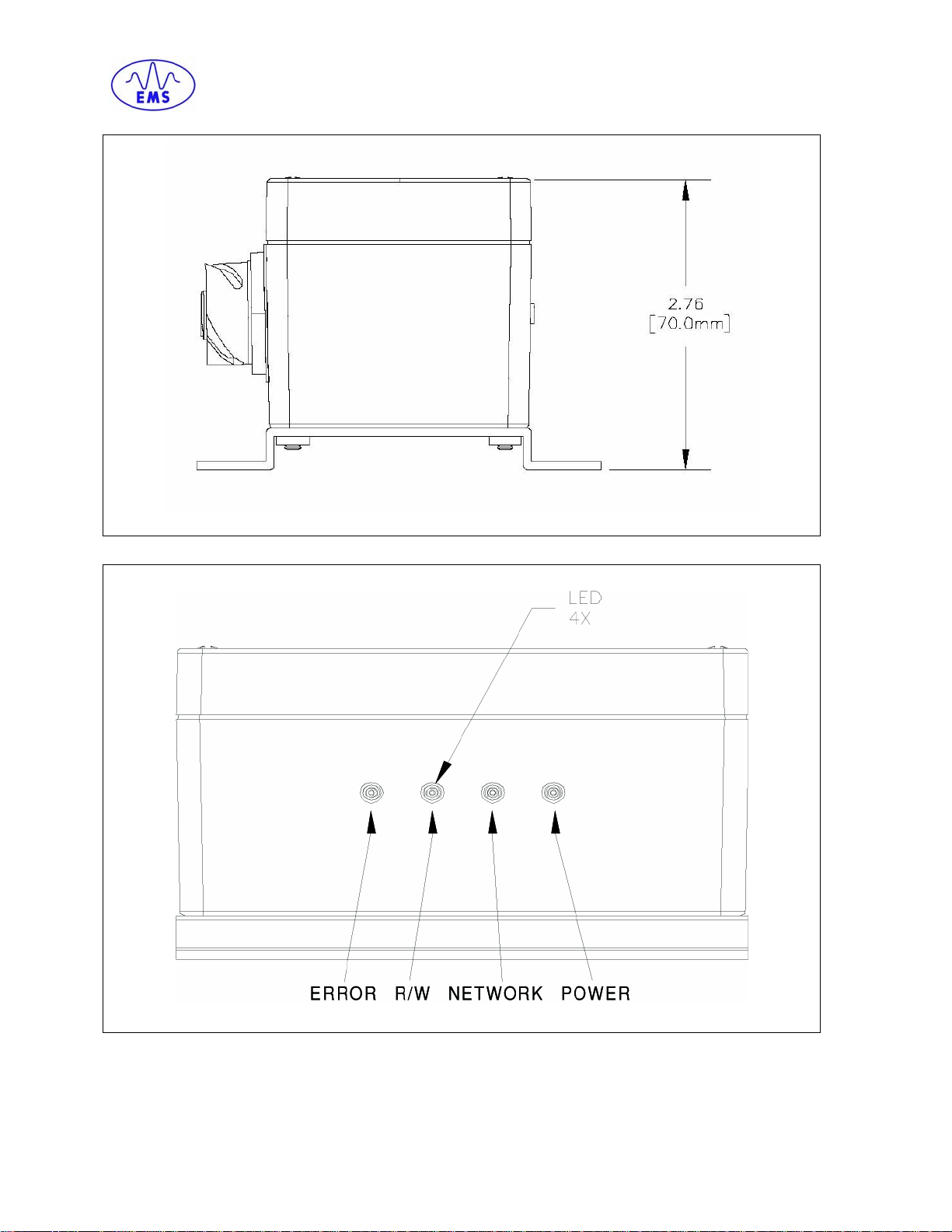
HS500E Side/Profile View
HS500E LEDs
HS500E – OPERATOR’S MANUAL P/N: 17-1305 REV 01.D (08-05)
PAGE 9 OF 51
CHAPTER 1: GETTING STARTED
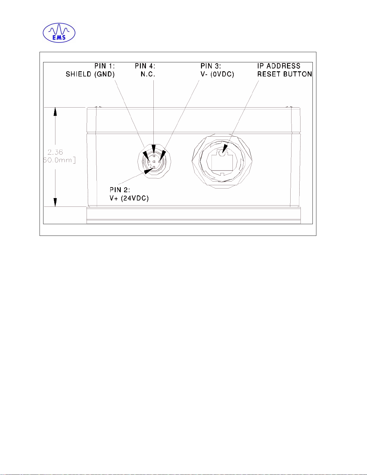
HS500E – Power & Ethernet Connections
HS500E – OPERATOR’S MANUAL P/N: 17-1305 REV 01.D (08-05)
PAGE 10 OF 51
CHAPTER 2: INTERFACING WITH THE HS500E
CHAPTER 2: INTERFACING WITH THE HS500E
The HS500E supports four different interface connections over Ethernet.
• MODBUS-TCP
• ETHERNET-IP
• TCP-IP
• OnDemand
The process of issuing commands and receiving responses depends on the interface
chosen and the Host computer that is connected to the HS500E.
This chapter contains a brief overview of how commands can be sent using the four
different interfaces listed above.
For additional information regarding the interface used by your particular RFID
application, please refer to the documentation for your Host software program.
HS500E – OPERATOR’S MANUAL P/N: 17-1305 REV 01.D (08-05)
PAGE 11 OF 51
CHAPTER 2: INTERFACING WITH THE HS500E
2.1 MODBUS-TCP INTERFACE
Note: Maximum number of registers transferred to/from an RFID tag per command
issued = 125 Registers (250 Bytes).
Commands must be placed in the Holding Register Area of Node 1, starting at
address 40001. Most commands utilize 6 registers (double-byte values or words).
The Write Data command will require more words to transmit the data used for the
Write.
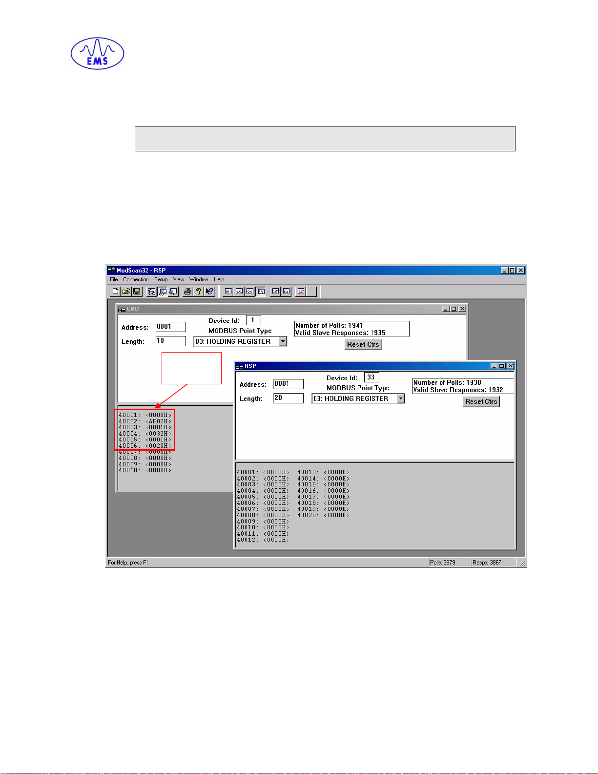
The first register, 40001, indicates the number of words in the Command Packet
(including the Overall Length). The command will trigger a respon se which will be
returned at Node Address 33 (Device ID 33), in registers 40001 and up. Below is an
example taken from Modscan32, a utility that implements ModBus on a PC.
Input
The input area is highlighted in red. When the value of the 40001 register for Node
Address 1 transitions from 0 to a non-zero length, the command will be issued by the
Host and executed by the HS500E. The resulting response is reported in the output
area at Node Address 33 (Device ID 33).
HS500E – OPERATOR’S MANUAL P/N: 17-1305 REV 01.D (08-05)
PAGE 12 OF 51
CHAPTER 2: INTERFACING WITH THE HS500E
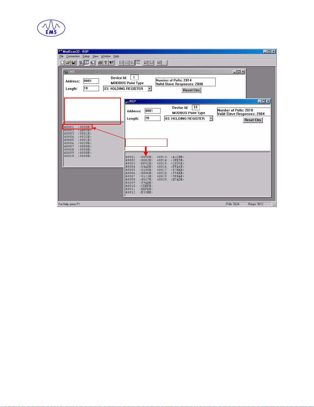
When the length is set at
40001, the command is
executed and the result
returned.
40001: <0006H>
When the command is completed, the HS500E will reset the length at 40001 of Node
Address 1 back to 0. This way a simple handshaking mechanism can be
implemented.
HS500E – OPERATOR’S MANUAL P/N: 17-1305 REV 01.D (08-05)
PAGE 13 OF 51
CHAPTER 2: INTERFACING WITH THE HS500E
2.2 ETHERNET/IP INTERFACE
The mechanism to send commands over Ethernet/IP is similar to that of MODBUSTCP. Commands must still be copied to the appropriate registers. However, the
mechanism for handshaking is different. For example, in a ControlLogix environment,
commands must be written to the ControlLogix tags that are generated when the
HS500E is added to the I/O Configuration.
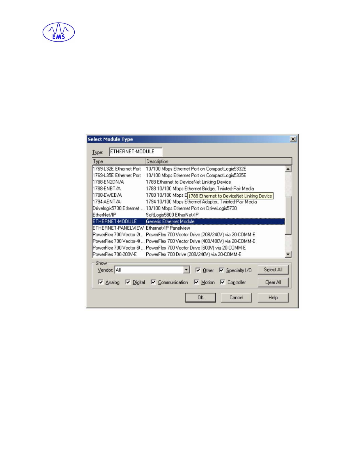
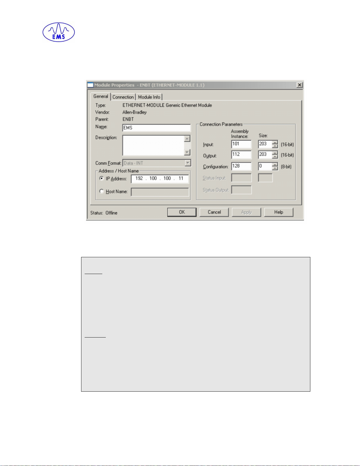
The first step is to add the HS500E to the ControlLogix PLC. To add the HS500E to
the PLC using RSLogix5000, right click on the Ethernet Bridge Device and select
“New Module…” Choose Generic Ethernet Module.
HS500E – OPERATOR’S MANUAL P/N: 17-1305 REV 01.D (08-05)
PAGE 14 OF 51
CHAPTER 2: INTERFACING WITH THE HS500E
Assign a name to the new device. In the example below, the device has been named
EMS. Configure the IP Address to match the IP Address of the HS500E. Match the
Connection Parameters to the image below.
After clicking the OK button, there will be predefined tags containing the specified I/O
Information.
Predefined Tags
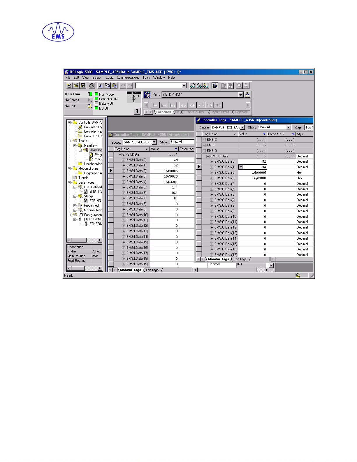
INPUT
EMS:I.Data [0] = Consume Data Sequence Number Handshake
EMS:I.Data [1] = Produce Data Sequence Number
EMS:I.Data [2] = Node 1 Serial Produce Data Size
EMS:I.Data [3-202] = Node 1 Serial Produce Data
OUTPUT
EMS:O.Data [0] = Produce Data Sequence Number Handshake
EMS:O.Data [1] = Consume Data Sequence Number
EMS:O.Data [2] = Node 1 Serial Consume Data Size
EMS:O.Data [3-202] = Node 1 Serial Consume Data
HS500E – OPERATOR’S MANUAL P/N: 17-1305 REV 01.D (08-05)
PAGE 15 OF 51
CHAPTER 2: INTERFACING WITH THE HS500E
The image below displays the input and output tags during the execution of a
command:
Commands are placed into the O.Data structure, beginning at word 2, while their
corresponding responses can be located in the I.Data structure again beginning at
word 2. The data located at words 0 and 1 are used for handshaking.
The device that produces the information must increment the sequence numbe r by
one for every data packet that is exchanged. The device that consumes the
information must echo the sequence number in the handshake location after the data
is processed. Valid sequence numbers are 1 to 65535, 0 is not allowed.
HS500E – OPERATOR’S MANUAL P/N: 17-1305 REV 01.D (08-05)
PAGE 16 OF 51
 Loading...