

Balluff LRP75 User Manual

OPERATOR’S MANU AL
LRP75 Long Range
Passive
Reader/Writer
Manual Revision 5, 9-02
Publication # 17-1289

Escort Memory Systems Warranty
Escort Memory Systems warrants that all products of its own manufacture conform to Escort Memory Systems specifications and are free from defects in material and workmanship when used under normal operating conditions and within the service conditions for which they were furnished. The obligation of Escort
Memory Sys tems hereunder shall expire one (1) year after delivery, unles s o ther wise s pec ified, and is lim it ed
to repairing, or at its option, replacing without charge, any such product which in Escort Memory System's
sole opinion prov es to be defec tive w it hin t he s cope of this Warrant y. In the event Es c ort Me mo ry System s i s
not able to repair or replace defective products or components within a reasonable time after receipt thereof,
Buyers shall be credited for their value at the original purchase price. Escort Memory Systems must be notified in writing of the defect or nonconformity within the warranty period and the affected product returned to
Escort Memory Systems factory or to an authorized service center within thirty (30) days after discovery of
such defect or nonconformity. Shipment shall not be made without prior authorization by Escort Memory
Systems.
This is Escort Memory Systems' sole warranty with respect to the products delivered hereunder. No statement, representation, agreement or understanding oral or written, made by an agent, distributor, representative, or employee of Escort Memory Systems which is not contained in this warranty, will be binding upon
Escort Memory Systems, unless made in writing and executed by an authorized Escort Memory Systems
employee. Escort Memory Systems makes no other warranty of any kind whatsoever, expressed or implied,
and all implied warranties of merchantability and fitness for a particular use which exceed the aforestated
obligation are hereby disclaimed by Escort Memory Systems and excluded from this agreement. Under no
circumsta nc es shall Es c ort Memory Sy stem s be liable t o Buy er , in co ntr act or in to rt, for any spec ial, indirect ,
incidental, or consequential damages, expenses, losses or delay however caused.
Equipment or parts which have been subject to abuse, misuse, accident, alteration, neglect, unauthorized
repair or ins t allat ion are not c ov ered by warranty . Es co rt Mem ory Systems shall mak e t he final determination
as to the existence and cause of any alleged defect. No liability is assumed for expendable items such as
lamps and fuses. No warranty is made with respect to custom equipment or products produced to Buyer's
specification s exc ept as specific ally stated in w riti ng by Esc ort Memory Sy stem s in the contra ct for suc h custom equipment.
This warranty is the only warranty made by Escort Memory Systems with respect to the goods delivered
hereunder, and may be modified or amended only by a written instr um ent signed by a duly author ize d of ficer
of Escort Memory Systems and ac cep ted by the Buye r .
Extended warranties of up to four years are available for purchase for most EMS products. Contact EMS or
your distributor for more inform at ion.
This document contains proprietary information which is protected by copyright. All rights are reserved. The
information in this manual has been carefully checked and is believed to be accurate; however, no responsibility is assumed for possible inaccuracies or omissio ns . S pecifications are subject to chan ge wi tho ut notic e.
EMS©, Escort Memory Systems™ and the EMS © logo are registered trademarks of Escort Memory Systems, a Datalogic Group Co mp any. Other brand and produc t names men tioned are trad em ark s or regist ered
trademarks of their res pec tive holders.
Escort Memo r y Sys te ms
A Datalogic Gro up Co mp any
170 Technology Circle
Scotts Valley, CA 95066
Telephone (831 ) 438-700 0
FAX (831) 438-5768
www.ems-rfid.com
email: info@em s- rfid .com

Table of C ontents
Chapter 1 Getting Started
1.1 Introduction. . . . . . . . . . . . . . . . . . . . . . . . . . . . . . . . . . . . . . . . . . 1
1.2 Unpacking and Inspection . . . . . . . . . . . . . . . . . . . . . . . . . . . . . . 1
1.3 FCC Compliance . . . . . . . . . . . . . . . . . . . . . . . . . . . . . . . . . . . . . 2
1.4 Changes and Modifications . . . . . . . . . . . . . . . . . . . . . . . . . . . . . 2
Chapter 2 Mechanical Specif ications
2.1 Dimensions. . . . . . . . . . . . . . . . . . . . . . . . . . . . . . . . . . . . . . . . . . 3
2.2 Mounting Options . . . . . . . . . . . . . . . . . . . . . . . . . . . . . . . . . . . . . 3
2.3 RF Range and Orientation . . . . . . . . . . . . . . . . . . . . . . . . . . . . . . 4
2.4 Locating the LRP75 . . . . . . . . . . . . . . . . . . . . . . . . . . . . . . . . . . . 4
2.4.1 Guidelines . . . . . . . . . . . . . . . . . . . . . . . . . . . . . . . . . . . . 5
Chapter 3 Power and Electrical Interface
3.1 Internal Junction Blocks . . . . . . . . . . . . . . . . . . . . . . . . . . . . . . . . 7
3.2 Power . . . . . . . . . . . . . . . . . . . . . . . . . . . . . . . . . . . . . . . . . . . . . . 7
3.2.1 Requirement . . . . . . . . . . . . . . . . . . . . . . . . . . . . . . . . . . 7
3.2.2 Connections . . . . . . . . . . . . . . . . . . . . . . . . . . . . . . . . . . . 8
3.3 Serial Communications. . . . . . . . . . . . . . . . . . . . . . . . . . . . . . . . . 8
3.4 RS232/RS422 Interface . . . . . . . . . . . . . . . . . . . . . . . . . . . . . . . . 8
3.5 Serial Connections . . . . . . . . . . . . . . . . . . . . . . . . . . . . . . . . . . . . 9
3.5.1 RS232 and Power Cable . . . . . . . . . . . . . . . . . . . . . . . . 10
3.5.2 Wiring . . . . . . . . . . . . . . . . . . . . . . . . . . . . . . . . . . . . . . . 10
3.6 LED Indicator . . . . . . . . . . . . . . . . . . . . . . . . . . . . . . . . . . . . . . . 11
Chapter 4 Configuration Menu
4.1 Introduction. . . . . . . . . . . . . . . . . . . . . . . . . . . . . . . . . . . . . . . . . 13
4.1.1 Using the EC Program . . . . . . . . . . . . . . . . . . . . . . . . . . 13
4.2 Configuration Menu . . . . . . . . . . . . . . . . . . . . . . . . . . . . . . . . . . 13
4.2.1 Set COM1 Parameters . . . . . . . . . . . . . . . . . . . . . . . . . . 14
4.2.2 Set Operating Mode . . . . . . . . . . . . . . . . . . . . . . . . . . . . 14
4.2.3 Downlo ad S of tw a r e Up d at e s . . . . . . . . . . . . . . . . . . . . . 16
Chapter 5 Standard RFID Interface
5.1 Introduction. . . . . . . . . . . . . . . . . . . . . . . . . . . . . . . . . . . . . . . . . 17
5.2 Command Timeout Values. . . . . . . . . . . . . . . . . . . . . . . . . . . . . 17
5.3 Address Blocks. . . . . . . . . . . . . . . . . . . . . . . . . . . . . . . . . . . . . . 18
5.4 ABx Error Codes. . . . . . . . . . . . . . . . . . . . . . . . . . . . . . . . . . . . . 19
5.4.1 ABx Standard Error Format . . . . . . . . . . . . . . . . . . . . . . 20
5.5 Command Descriptions . . . . . . . . . . . . . . . . . . . . . . . . . . . . . . . 20
5.6 ABx Standard Commands . . . . . . . . . . . . . . . . . . . . . . . . . . . . . 20
5.6.1 Command 4 (04 Hex): Tag Fill . . . . . . . . . . . . . . . . . . . . 20
5.6.2 Comma n d 5 (05 H e x) : B lo ck R ea d . . . . . . . . . . . . . . . . 22
5.6.3 Comma n d 6 (06 H e x) : B lo ck W ri te . . . . . . . . . . . . . . . . . 24
5.6.4 Command 7 (07H): Read Tag Serial Number . . . . . . . . 25
5.6.5 Command 8 (08 Hex): Tag Search . . . . . . . . . . . . . . . . 26
LRP75 Long Range Passive Reader/Writer i

Table of Contents
5.6.6 Command D (0D Hex): Start/Stop Conti nuous
Block Read . . . . . . . . . . . . . . . . . . . . . . . . . . . . . . . . . . 27
5.6.7 Command E (0EH) Read SN and Data . . . . . . . . . . . . . 30
5.6.8 Command F (0FH) Start/Stop Cont inuous Read
SN and Data . . . . . . . . . . . . . . . . . . . . . . . . . . . . . . . . . 31
5.7 ABx Fast Commands. . . . . . . . . . . . . . . . . . . . . . . . . . . . . . . . . 33
5.7.1 ABx Command Packet Structure . . . . . . . . . . . . . . . . . 33
5.7.2 Command 4 (04 Hex): Tag Fill . . . . . . . . . . . . . . . . . . . 35
5.7.3 Comma n d 5 (05 H e x) : B lo ck R ea d . . . . . . . . . . . . . . . . 38
5.7.4 Comma n d 6 (06 H e x) : B lo ck W ri te . . . . . . . . . . . . . . . . 40
5.7.5 Command 7 (07H): Read Tag Serial Number . . . . . . . . 42
5.7.6 Command 8 (08 Hex): Tag Search . . . . . . . . . . . . . . . . 44
5.7.7 Command D (0D Hex): Start/Stop Conti nuous
Block Read . . . . . . . . . . . . . . . . . . . . . . . . . . . . . . . . . . 45
5.7.8 Command E (0EH) Read SN and Data . . . . . . . . . . . . . 49
5.7.9 Command F (0FH) Start/Stop Cont inuous Read
SN and Data . . . . . . . . . . . . . . . . . . . . . . . . . . . . . . . . . 51
Appendix A Technical Specifications
A.1 Electrical Characteristics . . . . . . . . . . . . . . . . . . . . . . . . . . . . . 55
A.2 Physical Characteristics . . . . . . . . . . . . . . . . . . . . . . . . . . . . . . 55
A.3 Environmental . . . . . . . . . . . . . . . . . . . . . . . . . . . . . . . . . . . . . . 55
A.4 Communication Characteristics . . . . . . . . . . . . . . . . . . . . . . . . 55
Appendix B LRP75 Beta Connections
B.1 Internal Junction Blocks . . . . . . . . . . . . . . . . . . . . . . . . . . . . . . 57
B.2 Powe r Connections . . . . . . . . . . . . . . . . . . . . . . . . . . . . . . . . . . 57
B.3 Serial Connections . . . . . . . . . . . . . . . . . . . . . . . . . . . . . . . . . . 58
Appendix C Models and Accessories................................ 59
Appendix D ASCII Chart............................................................. 61
ii LRP75 Long Range Passive Reader/Writer

1.1 Introduction
Escort Memory Systems' passive read/write system is a complete
family of fiel d-proven read/write Radio-Fr equency Identification
products.
The system consists of RFID tags, reader/writers, antennas,
controllers, bus interfaces, and ancillary equipment. Tags can be
attached to a pr oduct or its carrier and act as an el ectronic identifier,
job sheet, por table database, or manifest. Tags are read and upda ted
via an Escort Memory Systems Reader/Writer, through any nonconducting material, while moving or st anding still.
Escort Memory Systems' LRP-Series long range passive RFID
system is the latest in our line of high performance, industrial RFID
equipment. The pas sive de sign of th e LRP read/ write system us es t he
RF field from the antenna to power the tag, eliminating t he need for
tag batter ies. The LRP passive read/write system is designed to
provide cost ef fective RFID data collection and control solutions to
automation and material handling applicat ions.
The LRP system uses the inter nation ally r ecog nized IS M frequency of
13.56 MHZ to both power the tag, and to establish a radio li nk to
transfer the information. LRP-Series passive tags provide 48 bytes of
reprogrammable memory.
1
Getting Started
The LRP75 is encased in a NEMA2 enclos ure. The LRP75 is
equipped with an internal antenna that has a range of 4 inches .
The LRP75 has one serial port that supports RS232 or RS422 serial
communications. The serial port is used to rece ive commands and
software from the host and to send the data back.
1.2 Unpacking and Inspection
When you unpack the LRP75, retain the original shipping carton and
packing material in case any item has to be returned to Escort
Memory Systems. Inspect each item carefully for evidence of
damage. If any item appe ars to be damaged, notify your Escort
Memory Systems repr esentative immediately.
The following is supplied with the LRP75:
1 LRP75
2 Short screws
2 Long screws
2 Threaded inserts
LRP75 Long Range Passive Reader/Writer 1

Getting Started
The following components are required for configuring a complete
system:
• LRP-Series Passi ve Read/Write Tags
• LRP75-to-host cable (user-supplied)
• RS232/RS422 host
• 24 V d c + / - 10%, 5 W po w e r supply
1.3 FCC Compliance
This equipment has been tested and found to comply with the limi ts
for a Class B digital device, pursuant to Part 15 of the FCC Rules.
These limit s are designed to provide reasona ble protection against
harmful inte rf erence in a residential installation. This equi pm ent
generates, uses and can radiate radio frequency energy and, if not
installed and used in accordance with the ins tr u ctions, may cause
harmful interference to radio communications. However, there is no
guarantee that interference will not occur in a particular installation. If
this equipment does cause harmful interfer ence to radio or television
reception, which can be determined by turning the equipment off and
on, the user is encou raged to try to correct the interference by one or
more of the following meas ures:
• Reorient or relocate the receiving antenna.
• Increase the separation between the equipment and receiver.
• Connect the equipment into an outlet on a circui t different from that
to which the receiver is connected.
• Consult the deal er or an experienced radio/TV techni cian for help.
1.4 Chang es and Modification s
Any changes or modifi cations to the LRP75 not expressly approved
by Escort Memo ry Systems, could vo id the user's author it y to operate
the equipment.
2 LRP75 Long Range Passive Reader/Writer
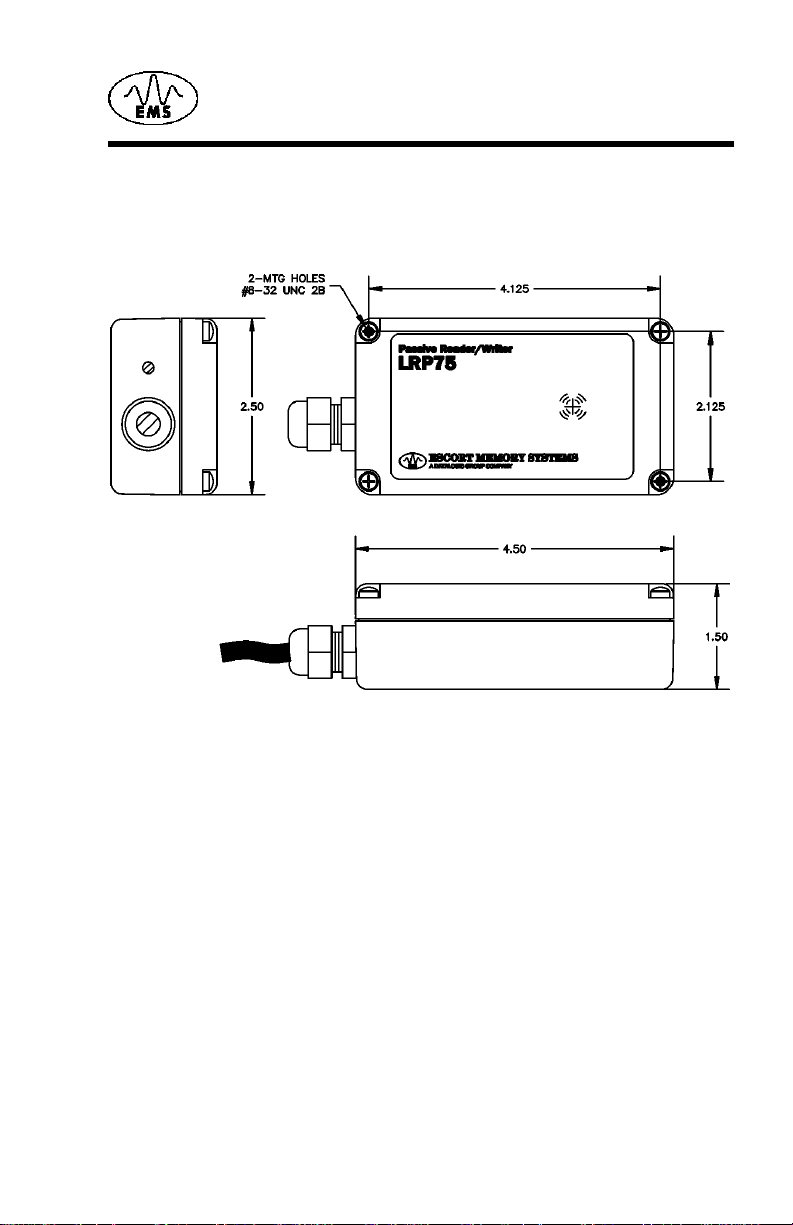
2.1 Dimensions
Figure 2-1 shows the dimensions and mounti ng hole locations for the
LRP75 Reader/Writer.
2
Mechanical Specifications
Figure 2-1. LRP75 dimensions and m ounting hole locations
2.2 Mounting Options
The LRP75 ships with mounting screws and threaded inserts to
provide mounting options. The LRP75 can be through-bolted with the
two longer screws or mounted with an adhesive backing such as
®
Velcro.
If you do not use the long screws to through-bolt the LRP75, you
should inst all the threaded inserts and use the short screws to secure
the lid.
To install the threaded inserts:
1. Place the LRP75 upsi de down on a fi rm surface.
2. Place the thread ed inserts, smooth end first, into the two holes
3. From the lid side of the LRP75, insert the scr ews and tight en them
LRP75 Long Range Passive Reader/Writer 3
and press in firmly.
until the inserts are flush with the bottom of LRP75.
Mechanical Spec ifications
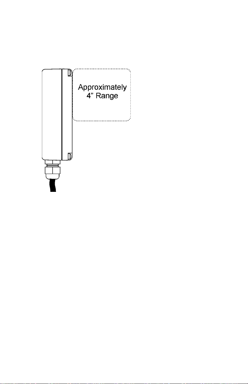
2.3 RF Range and Orientation
The following information should be considered when positioning the
LRP75. The path of the tags through the RF field should be within the
guaranteed reading/writing range unless sufficient site testing has
been performed to assure consistent RF communicat ions.
Figure 2-2. LRP75 reading range
2.4 Locating the LRP75
The reading range of the LRP75 i s pri m ari ly affected by two
environmental variables. The first, and most influential of th ese
variables, is the presenc e of metal or a ny other electric ally conductive
material withi n the range of the antenna. The reader can be safel y
mounted to a metal sur face without compromising t he reading range;
however, any conducti ve m aterial within the area in front of and to the
sides of the reader - anywhere a tag can be read - will affect t he
reading range to some extent. The most reliable method for
determining the ef fect s of met al on t he re ading r ange is t o p erform s ite
tests.
Electromagnetic radiation is the second environmental variable that
affects the reading range and overall pe rf ormance of the LRP75. The
reader should not be located close to any sources of electromagnetic
radiation. Do not mount a LRP75 closer than two meters from another
LRP75, and a greater dista nce from longer- range readers, such as th e
EMS LRP820. Again, si te t esting will provide the most rel iable means
to determine the read ra nge in a given environment.
4 LRP75 Long Range Passive Reader/Writer

2.4.1 Guidelines
• Isolate the LRP75 from electromagnetic radiation.
• Avoid surrounding the LRP75 with metal.
• Maintain at least two meters spacing between adjacent LRP75s.
• St ay within the guaranteed range of t he tag you are using.
• Conform with EIA RS232 and RS422 standards.
Mechanical Specifications
LRP75 Long Range Passive Reader/Writer 5

Mechanical Spec ifications
This page lef t bl ank intentionally.
6 LRP75 Long Range Passive Reader/Writer
Power and Electrical Interface
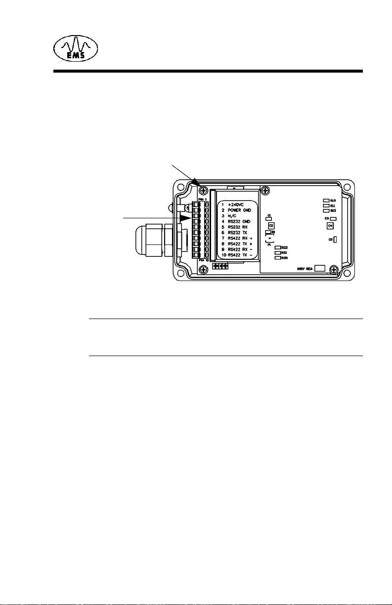
3.1 In ter n al Junction Blocks
The LRP75 is connected to external power and communications
cabling through an internal terminal strip. The power and serial
communication j un ction block ( J1) has 1 0 te rminal s and accept s AWG
22-14 wires.
Ground Screw
J1 Term inal Block
Figure 3-1. Internal junction block
NOTE:Earlier models of th e LR P75 have different power and serial
communications connections. For more information, see
Appendix B,
LRP75 Beta Connection s
3
.
3.2 Power
3.2.1 Requirement
The LRP75 power supply requirements are:
• 24 Vdc +/- 10%
• 5 Watts maximum consumption
The maximum current consumption at 24 Vdc is 200 mA.
LRP75 Long Range Passive Reader/Writer 7

Power and Electrical Interface
3.2.2 Connections
Connection to DC power is through pins 1 and 2 of the internal
terminal bl ock J1.
T able 3-1: J1 Power Connections
Terminal Description
1+24 Vdc
2 Power G round
3.3 Serial Communications
The LRP75 offers either RS232 or RS422 communications. The
RS422 option provides the superior reliabil ity over longer distances or
in noisy environm ents. Communication parameters, such as baud
rate, are set by the configuration program.
CAUTION:Do not bundle communications wiring with high current
power lines. This wi ll cause communications errors.
3.4 RS 23 2/RS 4 22 Int er fa ce
The LRP75 is set to automatically enter run mode seven second s
after power-on the device. This allows you to enter the configuration
program by entering a <control D> after power-on. If no com mands
are received by the reader/writer during the sev en seconds, the
LRP75 enter run mode with exist ing operating parameters. For more
information on the Configuration Menu refer to Chapter 4.
To communicate with the device via RS232, set the serial
communications parameters of the host as foll ows:
Baud rate 9600
Parity none
Data bits 8
St op bit 1
NOTE:The LRP75 automatically resets to 9600, N, 8,1 for seven
seconds whe never the power is cycled, after which it will apply
the setting made in the configuration menu.
8 LRP75 Long Range Passive Reader/Writer

3.5 Serial Connections
The LRP75 can be wired to communicate with th e host either through
an RS232 or RS422 interface. Connection to the serial interface is
through the J1 terminal shown in Figure 3-1 on page 7.
Table 3-2 gives the pinouts for the J1 terminal block.
T able 3-2: J1 Serial Communications Pinouts
Terminal Function
3 Reserv ed, no conne ction
4 Signal Ground (D B9, pin 5)
5 RS232 RX (wired to host DB9, pin 3)
6 RS232 TX (wired to host DB9, pin 2)
7RS422 RX +
8RS422 TX +
9RS422 RX 10 RS422 TX -
Power and Electri c al Interf ace
NOTE:In order to configure the unit for RS422, you must first
establish communications through RS232 and update the
communication parameters.
The signals and electrical loads should conform to the electrical
specifications of EIA Standar d for RS232 or RS422. The maximum
cable length spe cif ied for RS232 is 50 feet. Use the RS422 interface
for longer communications links. Use high qual ity shielded cable for
these connections.
LRP75 Long Range Passive Reader/Writer 9
Power and Electrical Interface
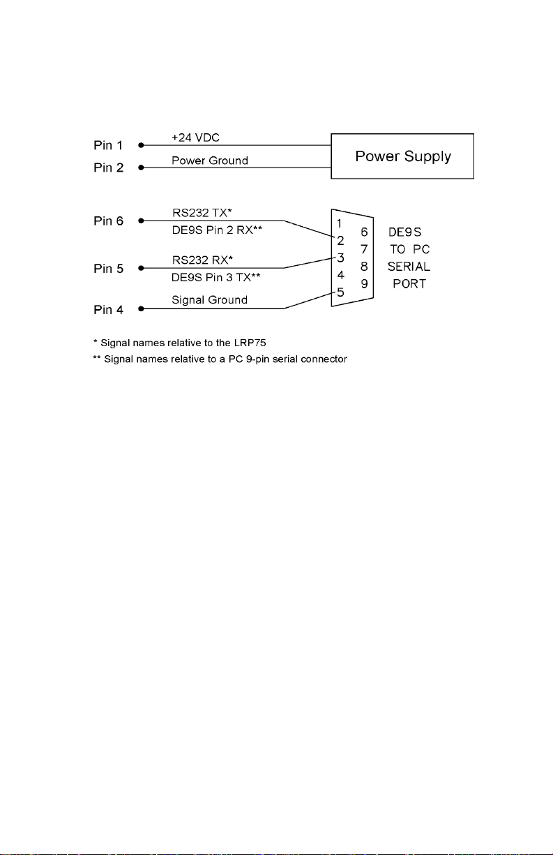
3.5.1 RS232 and Power Cable
Figure 3-2 shows how to construct a demonstrat ion cable with power
and RS232 serial communications to a PC host with a DE9 serial port
connector.
Figure 3-2. LRP75 to PC host demo
3.5.2 Wiring
Use shielded cable only. Connec t shi eld drain of the power and data
cabling to either ground on the J1 connector (terminal 2 or 4).
• Recommended cable f or RS422 i s Belden 3107A, 3108A or
compatible.
• Recommended cable f or RS232 i s Belden 9941 or compatible.
To fully comply with FCC and CE Regulations, wind the power and
data cabling around a type 43 ferrite toroid such as Fairrite™ part
number 2643803802 or Amidon™ part number FT- 240-43. Install the
toroid as close as possible to the LRP75’s gland nut. You must
connect the internal ground screw, shown in Figure 3-1 on page 7, to
the nearest earth ground outside the unit.
To make the ground conn ection, first terminate a length of 1/8-inch
copper braid with a ring terminal such as Panduit™ part number P18-
45. Fasten the ring terminal to the ground screw. For a tight seal,
chase the braid through the gland nut against the data and power
cabling.
10 LRP75 Long Range Passive Reader/Writer

To connect your cabl e to the LRP75:
1. Remove the cover of the antenna by loosening the four captive
screws.
2. Loosen the cord grip, feed the cable through the cord grip and
attach the wires to the terminal screws. Tighten the cord grip to
seal the cable. Use a cable of sufficient diameter to properly seal
with the cord grip. The recommended minimum O.D. is .125
inches (3.2 mm).
NOTE:Due to the small size of the LRP75 enclosure and gland nut,
you may have diffi culty sealing wires passing through the
gland nut. Olflex
available and will satisfy th e requir ement s of most appl ications .
3. Re-assemble the enclosure and secure the screws.
3.6 LED Ind ic ato r
The LRP75 has one bi-color LED indicating power on and activity on
the serial port. Table 3-3 shows the LED activi ty and meaning.
Table 3-3: LRP75 LED Indicator
LED Action LRP75 state Description
Power and Electri c al Interf ace
®
cable part number 911285 is readily
Slow RED
Blink
Fast RED
Blink
Steady
GREEN
GREEN
Blink
Short RED/
GREEN
Blink
LRP75 Long Range Passive Reader/Writer 11
Power-up or
reset
Configuration
mode
Idle The unit is ready for an ABx command.
LRP75
upgrade
Executing
Command
The LED wi ll fla sh R ED slow l y for ab ou t
seven seconds following power-up
during which time the user may send a
<Ctrl> D to enter configuration mode.
If the LRP75 receives a <Ctrl> D duri ng
the init ia l s ev en sec on d per i od , th e LE D
will flash at a faster rate until
configuration mode has been exited.
A steady GREEN LED indicates that the
seven second period has elapsed
with ou t entering co nf ig ur a tio n mode, or
configuration has been compl eted.
While d ownloading a new , or custom,
program to the LRP75, the LED will
blink GREEN.
While the reader/writer is occupied with
a command , the LED will be flashing
GREEN to RED. A RED to GREEN
flash indicates a tag is being searched
for, and the command is being
executed.

Power and Electrical Interface
Table 3-3: LRP75 LED Indicator
LED Action LRP75 state Description
RED and
GREEN
1. When Software Handshaking is enabled, and the host has sent
Executing
Continuous
Block Read
the LRP 7 5 an X O FF , the RED LED w il l b e on wh ile t he LRP75
transm it buffe r fills. The L ED wi ll rema in RE D until an XON is
received and the LRP buffer is emptied.
The LED will be both RED and GREEN
(orange) indicates the LRP75 is in
continuous mode. There is shor t RED
flash when data sen t to the host .
1
12 LRP75 Long Range Passive Reader/Writer

4.1 Introduction
The LRP75 contain s a confi gurati on progr am in EEPROM memory for
defining the dat a format an d serial prot ocol. Af ter the LRP75 has been
powered, it pa uses for seven seconds waiting fo r the command to
enter the configuration program. The communication parameters
during this se ven second period are:
• 9600 baud
• 8 data bits
•No parity
• 1 stop bit
Use a terminal emulation program (such as EC or HyperTermin al) to
send a <control D> within this seven second period to initialize the
Configuration Menu. If the LRP75 does not receive a <contr ol D>, it
will go "online" wi th th e existing user-defined set ti ngs.
4.1.1 Using the EC Program
The terminal emulati on program, EC.EXE, is recommended for
LRP75/Host communications. It can be downloaded from Escort
Memory Systems Web site (www.ems-rfid.com). Unlike many other
terminal emulati on programs, EC.EXE can transfer binar y data in
ASCII hex-based format, as required by the LRP75 commands. The
.HEX file downloads to the LRP are in Intel Hex format.
4
Configuration Menu
4.2 Configuration Menu
The Configuration Menu will display the current state of the operating
parameters. To cha nge a paramet er, enter the decimal number shown
in the menu for the option you want. An invalid entry will return you to
the Main Menu.
LRP75 Long Range Passive Reader/Writer 13

Configuratio n Menu
The Main Board Configuration menu displays the current main board
software version number together with the RFID firmwar e version.
******** LRP75/76 Standard Program V1.3E ********
RF module:4.01J
Serial Port COM1:RS232, 9600, N, 8, 1 No Handshake
Operating Mode:ABx Standard
Tag Type: Phillips I-CODE 1
[1] Set COM1 Parameters
[2] Set Operating Mode
[3] Set Tag Type
[4] Restore Factory Defaults
[5] Download New Program
[6] Download RFID Firmware
[7] Exit to Operating Mode
Enter Selection:
4.2.1 Set COM1 Parameters
The Set COM1 Parameters menu is given bel ow.
*** Set COM1 Parameters **
Operating mode? [0] RS232 [1] RS422
Baud Rate? [0] 1200 [1] 2400 [2] 4800 [3] 9600 [4] 19200
Data size? [0 ] 7bit [1] 8bit
Parity? [0 ] No ne [1 ] E ven [2 ] O d d
Handsh a ke [0 ] N o ne [1 ] X on / X off
Save Changes to EEPROM? [0] No [1] Yes
Enter the number corresponding to the parameter you wish to enable.
4.2.2 Set Operating Mode
The Set Operating Mode menu is given below.
*** Set Operating Mode ***
Commands Protocol? [0] ABx Standard [1] ABx Fast
Checksum? [0] Disabl ed [1] Enabled
Power up performing Conti nuous Read?
[0] NO
[1] Continuous Block Read (0DH) active
[2] Continuous Read SN and Data (0FH) active
-> 1
St art Address (0 to 47) 0
Length (1 to 48) 48
Delay Between Duplicate Decodes (0 to 60) 1
Raw Read Response? [0] NO [1] CR terminate [2] CR/LF
terminate 2
Save Changes to EEPROM? [0] No [1] Yes
14 LRP75 Long Range Passive Reader/Writer

Configuration Menu
The LRP75 supports ABx Standard and ABx Fast RFID comm and
protocols. Select your comman d protoco l from th is menu. I f you sele ct
ABx fast, you can select an optional checksum. For data delivery
verifica ti on to the host, it is recommended to have the checksum
enabled.
You can also select from three Run Mode types. The options are:
[0] NO
LRP75 will wait for an ABx command af ter reset. If you choose 0
(NO), then the LRP75 con figur ation is compl et e and you are giv en the
optio n to save the se ttings.
[1] Continuous Block Read (0DH) active
After reset, the LRP75 will be in Continuous Block Read Mode just as
if you had issued a Continuous Block Read (0DH) to the LRP75. You
must enter the t ag start address, read leng th, and the delay between
identical decodes values.
[2] Continuous Read SN and Data (0F H) active
After reset, the LRP75 will be performing Continuous Read SN Data.
This is the same as if the 0FH command had been issued to the
LRP75. You must enter the tag start address, read length, and the
delay between identical decodes values.
Raw Read Response
It is possible to set the LRP75 to only send raw tag data to the host .
The raw read data does not contain a header, length, command
number , or t erminat or. If the data on the ta g is all pri ntabl e ASCII, then
the entire pa cket can be printed on any terminal emulat or or EC.
To receive a raw read response, the LRP75 must be set to use ABx
Fast, and to sta rt in Continuous Block Read Run Mode.
Raw Read Response? [0] NO [1] CR terminate [2] CR/LF
terminate
If you choose the raw response option 0 (NO), then standa rd ABx
response packets are returned when a tag i s read. If you choose
option 1 or 2 (CR or CR/LF terminate) , t hen the entire header and
footer are remov ed from the response.
If you choose CR or CR/LF, then a carriage return (0DH) or carriage
return line feed (0DH, 0AH) is append to the raw string of data from
the tag. There is no header, length, com m and echo, footer, or
checksum in this r esponse string. Raw Read Response does not
allow any delivery or data verification.
LRP75 Long Range Passive Reader/Writer 15

Configuratio n Menu
4.2.3 Download Softwar e Up dat es
The mircocontroller software can be updated by entering the
'Download New Program' mode and sending an Intel Hex file.
Also, the RF firmwar e can be up dated, by means of the 'D ownload RF
firmware' mode. Use the HFD.EXE Windows application on the PC.
Detailed download instructions are supplied with any custom or
upgrade software.
16 LRP75 Long Range Passive Reader/Writer
 Loading...