


OPERATOR’S MANU AL
LRP76 Long Range
Passive
Reader/Writer
Manual Revision 2, 9-02
Publication # 17-1293

Escort Memory Systems Warranty
Escort Memory Systems warrants that all products of its own manufacture conform to Escort Memory Systems specifications and are free from defects in material and workmanship when used under normal operating conditions and within the service conditions for which they were furnished. The obligation of Escort
Memory Sys tems hereunder shall expire one (1) year after delivery, unles s o ther wise s pec ified, and is lim it ed
to repairing, or at its option, replacing without charge, any such product which in Escort Memory System's
sole opinion prov es to be defec tive w it hin t he s cope of this Warrant y. In the event Es c ort Me mo ry System s i s
not able to repair or replace defective products or components within a reasonable time after receipt thereof,
Buyers shall be credited for their value at the original purchase price. Escort Memory Systems must be notified in writing of the defect or nonconformity within the warranty period and the affected product returned to
Escort Memory Systems factory or to an authorized service center within thirty (30) days after discovery of
such defect or nonconformity. Shipment shall not be made without prior authorization by Escort Memory
Systems.
This is Escort Memory Systems' sole warranty with respect to the products delivered hereunder. No statement, representation, agreement or understanding oral or written, made by an agent, distributor, representative, or employee of Escort Memory Systems which is not contained in this warranty, will be binding upon
Escort Memory Systems, unless made in writing and executed by an authorized Escort Memory Systems
employee. Escort Memory Systems makes no other warranty of any kind whatsoever, expressed or implied,
and all implied warranties of merchantability and fitness for a particular use which exceed the aforestated
obligation are hereby disclaimed by Escort Memory Systems and excluded from this agreement. Under no
circumsta nc es shall Es c ort Memory Sy stem s be liable t o Buy er , in co ntr act or in to rt, for any spec ial, indirect ,
incidental, or consequential damages, expenses, losses or delay however caused.
Equipment or parts which have been subject to abuse, misuse, accident, alteration, neglect, unauthorized
repair or ins t allat ion are not c ov ered by warranty . Es co rt Mem ory Systems shall mak e t he final determination
as to the existence and cause of any alleged defect. No liability is assumed for expendable items such as
lamps and fuses. No warranty is made with respect to custom equipment or products produced to Buyer's
specification s exc ept as specific ally stated in w riti ng by Esc ort Memory Sy stem s in the contra ct for suc h custom equipment.
This warranty is the only warranty made by Escort Memory Systems with respect to the goods delivered
hereunder, and may be modified or amended only by a written instr um ent signed by a duly author ize d of ficer
of Escort Memory Systems and ac cep ted by the Buye r .
Extended warranties of up to four years are available for purchase for most EMS products. Contact EMS or
your distributor for more inform at ion.
This document contains proprietary information which is protected by copyright. All rights are reserved. The
information in this manual has been carefully checked and is believed to be accurate; however, no responsibility is assumed for possible inaccuracies or omissio ns . S pecifications are subject to chan ge wi tho ut notic e.
EMS©, Escort Memory Systems™ and the EMS © logo are registered trademarks of Escort Memory Systems, a Datalogic Group Co mp any. Other brand and produc t names men tioned are trad em ark s or regist ered
trademarks of their res pec tive holders.
Escort Memo r y Sys te ms
A Datalogic Gro up Co mp any
170 Technology Circle
Scotts Valley, CA 95066
Telephone (831 ) 438-700 0
FAX (831) 438-5768
www.ems-rfid.com
email: info@em s- rfid .com

Table of C ontents
Chapter 1 Getting Started
1.1 Introduction. . . . . . . . . . . . . . . . . . . . . . . . . . . . . . . . . . . . . . . . . . 1
1.2 Unpacking and Inspection . . . . . . . . . . . . . . . . . . . . . . . . . . . . . . 2
1.3 FCC Compliance . . . . . . . . . . . . . . . . . . . . . . . . . . . . . . . . . . . . . 2
1.4 Changes and Modifications . . . . . . . . . . . . . . . . . . . . . . . . . . . . . 2
Chapter 2 Mechanical Specif ications
2.1 Dimensions. . . . . . . . . . . . . . . . . . . . . . . . . . . . . . . . . . . . . . . . . . 3
2.2 Mounting Options . . . . . . . . . . . . . . . . . . . . . . . . . . . . . . . . . . . . . 4
2.3 RF Range and Orientation . . . . . . . . . . . . . . . . . . . . . . . . . . . . . . 4
2.4 Locating the LRP76 . . . . . . . . . . . . . . . . . . . . . . . . . . . . . . . . . . . 4
2.4.1 Guidelines . . . . . . . . . . . . . . . . . . . . . . . . . . . . . . . . . . . . 5
Chapter 3 Power and Electrical Interface
3.1 Internal Junction Blocks . . . . . . . . . . . . . . . . . . . . . . . . . . . . . . . . 7
3.2 Power . . . . . . . . . . . . . . . . . . . . . . . . . . . . . . . . . . . . . . . . . . . . . . 7
3.2.1 Requirement . . . . . . . . . . . . . . . . . . . . . . . . . . . . . . . . . . 7
3.2.2 Connections . . . . . . . . . . . . . . . . . . . . . . . . . . . . . . . . . . . 8
3.3 Serial Communications. . . . . . . . . . . . . . . . . . . . . . . . . . . . . . . . . 8
3.4 RS232/RS422 Interface . . . . . . . . . . . . . . . . . . . . . . . . . . . . . . . . 8
3.5 Serial Connections . . . . . . . . . . . . . . . . . . . . . . . . . . . . . . . . . . . . 9
3.5.1 RS232 and Power Cable . . . . . . . . . . . . . . . . . . . . . . . . 10
3.5.2 Wiring . . . . . . . . . . . . . . . . . . . . . . . . . . . . . . . . . . . . . . . 10
3.6 LED Indicator . . . . . . . . . . . . . . . . . . . . . . . . . . . . . . . . . . . . . . . 11
Chapter 4 Configuration Menu
4.1 Introduction. . . . . . . . . . . . . . . . . . . . . . . . . . . . . . . . . . . . . . . . . 13
4.1.1 Using the EC Program . . . . . . . . . . . . . . . . . . . . . . . . . . 13
4.2 Configuration Menu . . . . . . . . . . . . . . . . . . . . . . . . . . . . . . . . . . 14
4.2.1 Set COM1 Parameters . . . . . . . . . . . . . . . . . . . . . . . . . . 14
4.2.2 Set Operating Mode . . . . . . . . . . . . . . . . . . . . . . . . . . . . 14
4.2.3 Downlo ad S of tw a r e Up d at e s . . . . . . . . . . . . . . . . . . . . . 16
Chapter 5 Standard RFID Interface
5.1 Introduction. . . . . . . . . . . . . . . . . . . . . . . . . . . . . . . . . . . . . . . . . 17
5.2 Command Timeout Values. . . . . . . . . . . . . . . . . . . . . . . . . . . . . 17
5.3 Address Blocks. . . . . . . . . . . . . . . . . . . . . . . . . . . . . . . . . . . . . . 18
5.4 ABx Error Codes. . . . . . . . . . . . . . . . . . . . . . . . . . . . . . . . . . . . . 19
5.4.1 ABx Standard Error Format . . . . . . . . . . . . . . . . . . . . . . 20
5.5 Command Descriptions . . . . . . . . . . . . . . . . . . . . . . . . . . . . . . . 20
5.6 ABx Standard Commands . . . . . . . . . . . . . . . . . . . . . . . . . . . . . 20
5.6.1 Command 4 (04 Hex): Tag Fill . . . . . . . . . . . . . . . . . . . . 20
5.6.2 Comma n d 5 (05 H e x) : B lo ck R ea d . . . . . . . . . . . . . . . . 22
5.6.3 Comma n d 6 (06 H e x) : B lo ck W ri te . . . . . . . . . . . . . . . . . 24
5.6.4 Command 7 (07H): Read Tag Serial Number . . . . . . . . 26
5.6.5 Command 8 (08 Hex): Tag Search . . . . . . . . . . . . . . . . 27
LRP76 Long Range Passive Reader/Writer i

Table of Contents
5.6.6 Command D (0D Hex): Start/Stop Conti nuous
Block Read . . . . . . . . . . . . . . . . . . . . . . . . . . . . . . . . . . 28
5.6.7 Command E (0EH) Read SN and Data . . . . . . . . . . . . . 30
5.6.8 Command F (0FH) Start/Stop Cont inuous Read
SN and Data . . . . . . . . . . . . . . . . . . . . . . . . . . . . . . . . . 31
5.7 ABx Fast Commands. . . . . . . . . . . . . . . . . . . . . . . . . . . . . . . . . 33
5.7.1 ABx Command Packet Structure . . . . . . . . . . . . . . . . . 33
5.7.2 Command 4 (04 Hex): Tag Fill . . . . . . . . . . . . . . . . . . . 36
5.7.3 Comma n d 5 (05 H e x) : B lo ck R ea d . . . . . . . . . . . . . . . . 38
5.7.4 Comma n d 6 (06 H e x) : B lo ck W ri te . . . . . . . . . . . . . . . . 40
5.7.5 Command 7 (07H): Read Tag Serial Number . . . . . . . . 42
5.7.6 Command 8 (08 Hex): Tag Search . . . . . . . . . . . . . . . . 44
5.7.7 Command D (0D Hex): Start/Stop Conti nuous
Block Read . . . . . . . . . . . . . . . . . . . . . . . . . . . . . . . . . . 46
5.7.8 Command E (0EH) Read SN and Data . . . . . . . . . . . . . 49
5.7.9 Command F (0FH) Start/Stop Cont inuous Read
SN and Data . . . . . . . . . . . . . . . . . . . . . . . . . . . . . . . . . 51
Appendix A Technical Specifications
A.1 Electrical Characteristics . . . . . . . . . . . . . . . . . . . . . . . . . . . . . 55
A.2 Physical Characteristics . . . . . . . . . . . . . . . . . . . . . . . . . . . . . . 55
A.3 Environmental . . . . . . . . . . . . . . . . . . . . . . . . . . . . . . . . . . . . . . 55
A.4 Communication Characteristics . . . . . . . . . . . . . . . . . . . . . . . . 55
Appendix B Models and Accessories................................ 57
Appendix CASCII Chart.............................................................. 59
ii LRP76 Long Range Passive Reader/Writer

1.1 Introduction
Escort Memory Systems' passive read/write system is a complete
family of fiel d-proven read/write Radio-Fr equency Identification
products.
The system consists of RFID tags, reader/writers, antennas,
controllers, bus interfaces, and ancillary equipment. Tags can be
attached to a pr oduct or its carrier and act as an el ectronic identifier,
job sheet, por table database, or manifest. Tags are read and upda ted
via an Escort Memory Systems Reader/Writer, through any nonconducting material, while moving or st anding still.
Escort Memory Systems' LRP-Series long range passive RFID
system is the latest in our line of high performance, industrial RFID
equipment. The pas sive de sign of th e LRP read/ write system us es t he
RF field from the antenna to power the tag, eliminating t he need for
tag batter ies. The LRP passive read/write system is designed to
provide cost ef fective RFID data collection and control solutions to
automation and material handling applicat ions.
The LRP system uses the inter nation ally r ecog nized IS M frequency of
13.56 MHZ to both power the tag, and to establish a radio li nk to
transfer the information. LRP-Series passive tags provide 48 bytes of
reprogrammable memory.
1
Getting Started
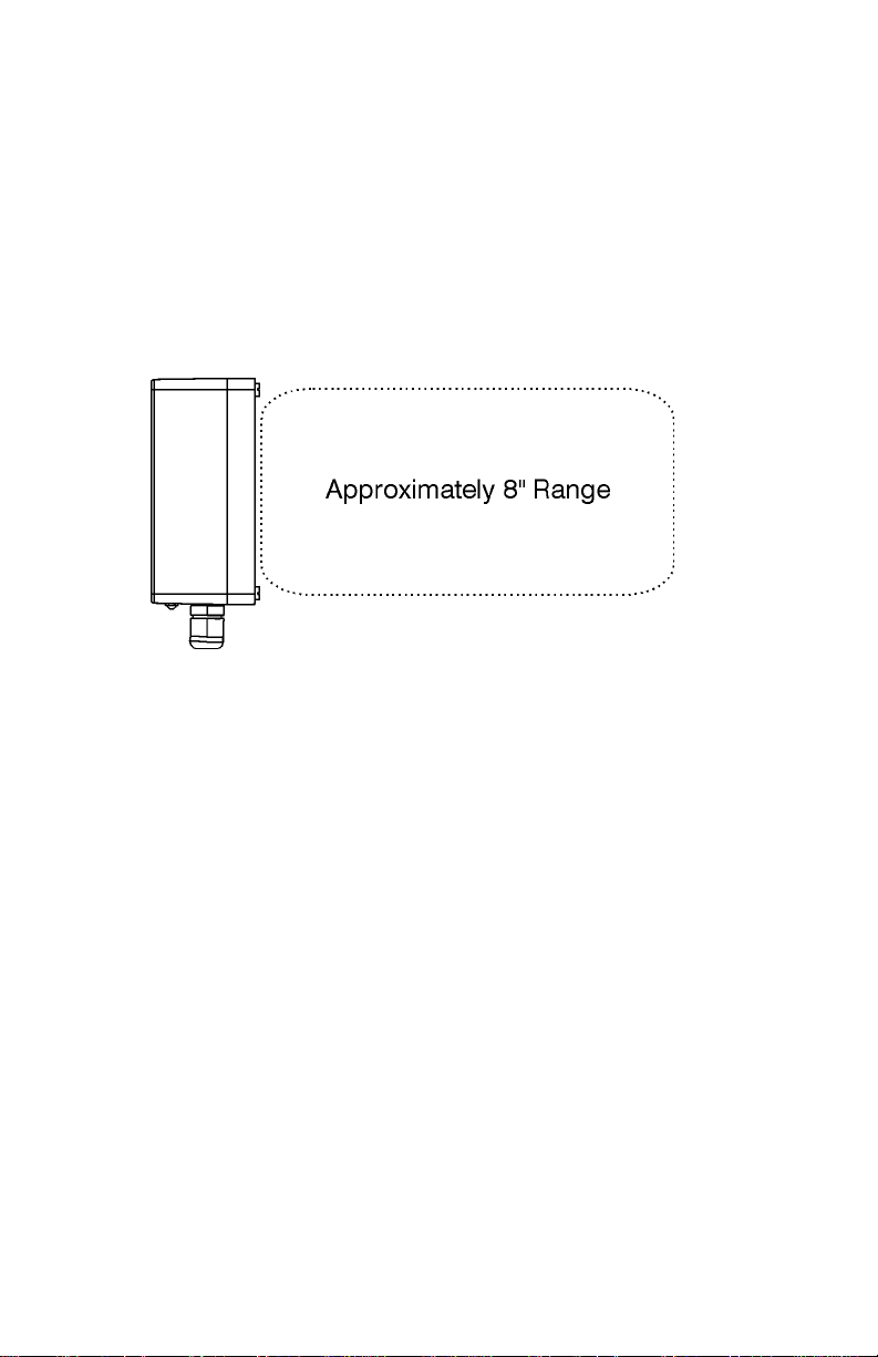
The LRP76 is encased in a NEMA2 enclos ure. The LRP76 is
equipped with an internal antenna that has a range of 8 inches .
The LRP76 has one serial port that supports RS232 or RS422 serial
communications. The serial port is used to rece ive commands and
software from the host and to send the data back.
LRP76 Long Range Passive Reader/Writer 1

Getting Started
1.2 Unpacking and Inspection
When you unpack the LRP76, retain the original shipping carton and
packing mate rial in case any item has to be returned to Escort
Memory Systems. Inspect each item carefully for evidence of
damage. If any item appe ars to be damaged, notify your Escort
Memory Systems repr esentative immediately.
The following components are required for configuring a complete
system:
• LRP-Series Passi ve Read/Write Tags
• LRP76-to-host cable (user-supplied)
• RS232/RS422 host
• 24 Vdc ±10%, 5 W power supply
1.3 FCC Compliance
This equipment has been tested and found to comply with the limi ts
for a Class B digital device, pursuant to Part 15 of the FCC Rules.
These limit s are designed to provide reasona ble protection against
harmful inte rf erence in a residential installation. This equi pm ent
generates, uses and can radiate radio frequency energy and, if not
installed and used in accordance with the ins tr u ctions, may cause
harmful interference to radio communications. However, there is no
guarantee that interference will not occur in a particular installation. If
this equipment does cause harmful interfer ence to radio or television
reception, which can be determined by turning the equipment off and
on, the user is encou raged to try to correct the interference by one or
more of the following meas ures:
• Reorient or relocate the receiving antenna.
• Increase the separation between the equipment and receiver.
• Connect the equipment into an outlet on a circui t different from that
to which the receiver is connected.
• Consult the deal er or an experienced radio/TV techni cian for help.
1.4 Chang es and Modification s
Any changes or modifi cations to the LRP76 not expressly approved
by Escort Memo ry Systems, could vo id the user's author it y to operate
the equipment.
2 LRP76 Long Range Passive Reader/Writer
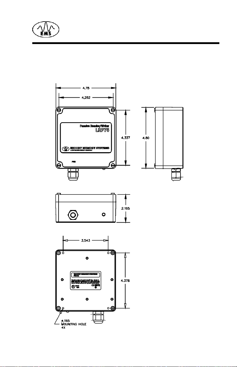
2.1 Dimensions
Figure 2-1 shows the dimensions and mounti ng hole locations for the
LRP76 Reader/Writer.
2
Mechanical Specifications
Figure 2-1. LRP76 dimensions and m ounting hole locations
LRP76 Long Range Passive Reader/Writer 3
Mechanical Spec ifications
2.2 Mounting Options
The LRP76 can be mounted with scr ews or an adhesive bac king such
as Velcro.
®
2.3 RF Range and Orientation
The following information should be considered when positioning the
LRP76. The path of the tags through the RF field should be within the
guaranteed reading/writing range unless sufficient site testing has
been performed to assure consistent RF communicat ions.
Figure 2-2. LRP76 reading range
2.4 Locating the LRP76
The reading range of the LRP76 i s pri m ari ly affected by two
environmental variables. The first, and most influential of th ese
variables, is the presenc e of metal or a ny other electric ally conductive
material withi n the range of the antenna. The reader can be safel y
mounted to a metal sur face without compromising t he reading range;
however, any conducti ve m aterial within the area in front of and to the
sides of the reader - anywhere a tag can be read - will affect t he
reading range to some extent. The most reliable method for
determining the ef fect s of met al on t he re ading r ange is t o p erform s ite
tests.
Electromagnetic radiation is the second environmental variable that
affects the reading range and overall pe rf ormance of the LRP76. The
reader should not be located close to any sources of electromagnetic
radiation. Do not mount a LRP76 closer than two meters from another
LRP76, and a greater dista nce from longer- range readers, such as th e
EMS LRP820. Again, si te t esting will provide the most rel iable means
to determine the read ra nge in a given environment.
4 LRP76 Long Range Passive Reader/Writer

2.4.1 Guidelines
• Isolate the LRP76 from electromagnetic radiation.
• Avoid surrounding the LRP76 with metal.
• Maintain at least two meters spacing between adjacent LRP76s.
• St ay within the guaranteed range of t he tag you are using.
• Conform with EIA RS232 and RS422 standards.
Mechanical Specifications
LRP76 Long Range Passive Reader/Writer 5

Mechanical Spec ifications
This page lef t bl ank intentionally.
6 LRP76 Long Range Passive Reader/Writer
Power and Electrical Interface
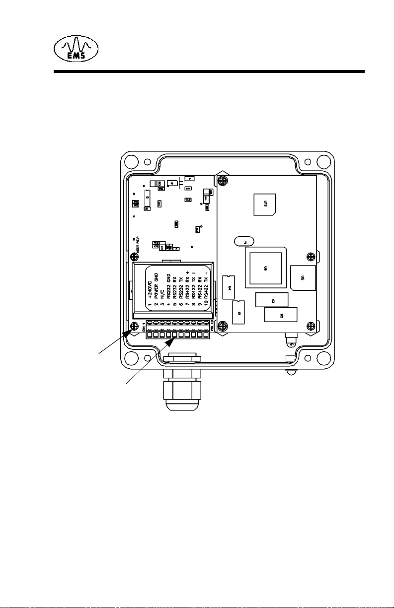
3.1 In ter n al Junction Blocks
The LRP76 is connected to external power and communications
cabling th rough an internal terminal strip s. The terminal accepts AWG
22-14 wires.
3
Ground Sc rew
J1 Terminal Block
Figure 3-1. Internal junction block
3.2 Power
3.2.1 Requirement
The LRP76 power supply requirements are:
• 24 Vdc +/- 10%
• 5 Watts maximum consumption
The maximum current consumption at 24 Vdc is 200 mA.
LRP76 Long Range Passive Reader/Writer 7

Power and Electrical Interface
3.2.2 Connections
Connection to DC power is through pins 1 and 2 of the internal J1
terminal bl ock.
T able 3-1: J1 Power Connection
Terminal Description
1+24Vdc
2 Power G round
3.3 Serial Communications
The LRP76 offers either RS232 or RS422 communications. The
RS422 option provides the superior reliabil ity over longer distances or
in noisy environm ents. Communication parameters, such as baud
rate, are set by the configuration program.
CAUTION:Do not bundle communications wiring with high current
power lines. This wi ll cause communications errors.
3.4 RS 23 2/RS 4 22 Int er fa ce
The LRP76 is set to automatically enter run mode seven second s
after power-on the device. This allows you to enter the configuration
program by entering a <control D> after power-on. If no com mands
are received by the reader/writer during the sev en seconds, the
LRP76 enters run mode with existing operating parameters. For more
information on the Configuration Menu refer to Chapter 4.
To communicate with the device via RS232, set the serial
communications parameters of the host as foll ows:
Baud rate 9600
Parity none
Data bits 8
St op bit 1
NOTE:The LRP76 automatically resets to 9600, N, 8,1 for seven
seconds whe never the power is cycled, after which it will apply
the setting made in the configuration menu.
8 LRP76 Long Range Passive Reader/Writer

3.5 Serial Connections
The LRP76 can be wired to communicate with th e host either through
an RS232 or RS422 interface. Connection to the serial interface is
through the J1 terminal shown in Figure 3-1 on page 7. Connect the
signal ground to terminal 4 on the J1 terminal.
Table 3-2 gives the communication pins for the J1 terminal block .
T able 3-2: J1 Serial Communications Pinouts
Terminal Function
3 Reserv ed, no conne ction
4 Signal Ground (D B9, pin 5)
5 RS232 RX (wired to host DB9, pin 3)
6 RS232 TX (wired to host DB9, pin 2)
7RS422 RX +
8RS422 TX +
9RS422 RX -
10 RS422 TX -
Power and Electri c al Interf ace
NOTE:In order to configure the unit for RS422, you must first
establish communications through RS232 and update the
communications parameters.
The signals and electrical loads should conform to the electrical
specifications of EIA Standar d for RS232 or RS422. The maximum
cable length spe cif ied for RS232 is 50 feet. Use the RS422 interface
for longer communications links. Use high qual ity shielded cable for
these connections.
LRP76 Long Range Passive Reader/Writer 9
Power and Electrical Interface
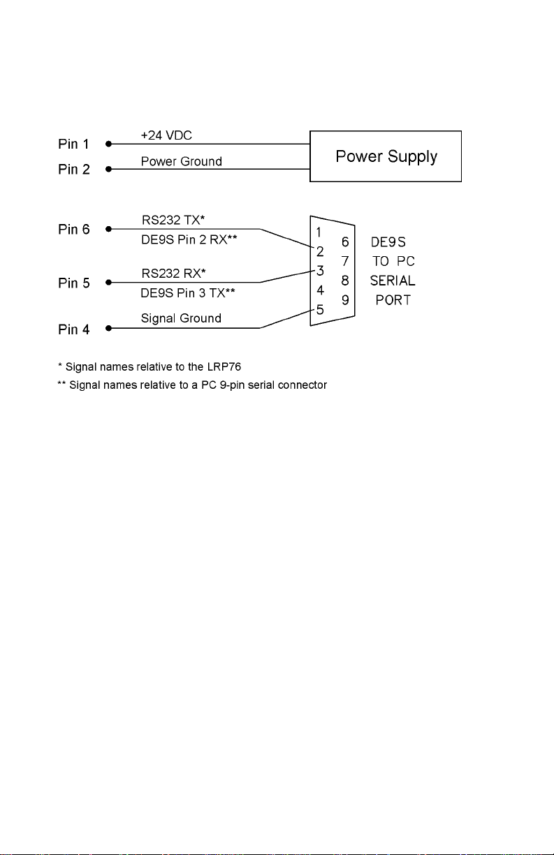
3.5.1 RS232 and Power Cable
Figure 3-2 shows how to construct a demonstrat ion cable with power
and RS232 serial communications to a PC host with a DE9 serial port
connector.
Figure 3-2. LRP76 to PC host demo cable
3.5.2 Wiring
Use shielded cable only. Connec t shi eld drain of the power and data
cabling to either ground on the J1 connector (terminal 2 or 4).
• Recommended cable f or RS422 i s Belden 3107A, 3108A or
compatible.
• Recommended cable f or RS232 i s Belden 9941or compatible.
To fully comply with FCC and CE Regulations, wind the power and
data cabling around a type 43 ferrite toroid such as Fairrite™ part
number 2643803802 or Amidon™ part number FT- 240-43. Install the
toroid as close as possible to the LRP76’s gland nut. You must
connect the internal ground screw, shown in Figure 3-1 on page 7, to
the nearest earth ground outside the unit.
To make the ground conn ection, first terminate a length of 1/8-inch
copper braid with a ring terminal such as Panduit™ part number P18-
45. Fasten the ring terminal to the ground screw. For a tight seal,
chase the braid through the gland nut against the data and power
cabling.
10 LRP76 Long Range Passive Reader/Writer

To connect your cabl e to the LRP76:
1. Remove the cover of the antenna by loosening the four captive
screws.
2. Loosen the cord grip, feed the cable through the cord grip and
attach the wires to the terminal screws. Tighten the cord grip to
seal the cable. Use a cable of sufficient diameter to properly seal
with the cord grip. The recommended minimum O.D. is .125
inches (3.2 mm).
NOTE:Due to the small size of the LRP76 enclosure and gland nut,
you may have dif ficul ty seal ing th e power and communi cati ons
wires pass ing th roug h the gl and nut . Olflex
91 1285 is readily available and will satisfy the requirements of
most applicat ions.
3. Re-assemble the enclosure and secure the screws.
3.6 LED Ind ic ato r
The LRP76 has one bi-color LED indicating power on and activity on
the serial port. Table 3-3 shows the LED activi ty and meaning.
Table 3-3: LRP76 LED Indicator
LED Action LRP76 state Description
Power and Electri c al Interf ace
®
cable part number
Slow RED
Blink
Fast RED
Blink
Steady
GREEN
GREEN
Blink
LRP76 Long Range Passive Reader/Writer 11
Power-up or
reset
Configuration
mode
Idle The unit is ready for an ABx command.
LRP76
upgrade
The LED wi ll fla sh R ED slow l y for ab ou t
seven seconds following power-up
during which time the user may send a
<Ctrl> D to enter configuration mode.
If the LRP76 receives a <Ctrl> D duri ng
the init ia l s ev en sec on d per i od , th e LE D
will flash at a faster rate until
configuration mode has been exited.
A steady GREEN LED indicates that the
seven second period has elapsed
with ou t entering co nf ig ur a tio n mode, or
configuration has been compl eted.
While d ownloading a new , or custom,
program to the LRP76, the LED will
blink GREEN.

Power and Electrical Interface
Table 3-3: LRP76 LED Indicator
LED Action LRP76 state Description
Short RED/
GREEN
Blink
RED and
GREEN
1. When Software Handshaking is enabled, and the host has sent
Executing
Command
Executing
Continuous
Block Read
the LRP 7 6 an X O FF , the RED LED w il l b e on wh ile t he LRP76
transm it buffe r fills. The L ED wi ll rema in RE D until an XON is
received and the LRP buffer is emptied.
While the reader/writer is occupied with
a command , the LED will be flashing
GREEN to RED. A RED to GREEN
flash indicates a tag is being searched
for, and the co mmand is being
executed.
The LED will be both RED and GREEN
(orange) indicates the LRP76 is in
continuous mode. There is shor t RED
flash when data sen t to the host .
1
12 LRP76 Long Range Passive Reader/Writer

4.1 Introduction
The LRP76 contain s a confi gurati on progr am in EEPROM memory for
defining the dat a format an d serial prot ocol. Af ter the LRP76 has been
powered, it pa uses for seven seconds waiting fo r the command to
enter the configuration program. The communication parameters
during this se ven second period are:
• 9600 baud
• 8 data bits
•No parity
• 1 stop bit
Use a terminal emulation program (such as EC or HyperTermin al) to
send a <control D> within this seven second period to initialize the
Configuration Menu. If the LRP76 does not receive a <contr ol D>, it
will go "online" wi th th e existing user-defined set ti ngs.
4.1.1 Using the EC Program
The terminal emulati on program, EC.EXE, is recommended for
LRP76/Host communications. It can be downloaded from Escort
Memory Systems Web site (www.ems-rfid.com). Unlike many other
terminal emulati on programs, EC.EXE can transfer binar y data in
ASCII hex-based format, as required by the LRP76 commands.
The.HEX file downloads to the LRP are in Intel Hex for m at.
4
Configuration Menu
LRP76 Long Range Passive Reader/Writer 13

Configuratio n Menu
4.2 Configuration Menu
The Configuration Menu will display the current state of the operating
parameters. To cha nge a paramet er, enter the decimal number shown
in the menu for the option you want. An invalid entry will return you to
the Main Menu.
The Main Board Configuration menu displays the current main board
software version number together with the RFID firmwar e version.
******** LRP75/76 Standard Program V1.3E ********
RF module:4.01J
Serial Port COM1:RS232, 9600, N, 8, 1 No Handshake
Operating Mode:ABx Standard
Tag Type: Phillips I-CODE 1
[1] Set COM1 Parameters
[2] Set Operating Mode
[3] Set Tag Type
[4] Restore Factory Defaults
[5] Download New Program
[6] Download RFID Firmware
[7] Exit to Operating Mode
Enter Selection:
4.2.1 Set COM1 Parameters
The Set COM1 Parameters menu is given bel ow.
*** Set COM1 Parameters **
Operating mode? [0] RS232 [1] RS422
Baud Rate? [0] 1200 [1] 2400 [2] 4800 [3] 9600 [4] 19200
Data size? [0 ] 7bit [1] 8bit
Parity? [0 ] No ne [1 ] E ven [2 ] O d d
Handsh a ke [0 ] N o ne [1 ] X on / X off
Save Changes to EEPROM? [0] No [1] Yes
Enter the number corresponding to the parameter you wish to enable.
4.2.2 Set Operating Mode
The Set Operating Mode menu is given below.
*** Set Operating Mode ***
Commands Prot ocol? [0] ABx Standard [1] ABx Fast
Checksum? [ 0] Disabled [1] Enabled
Power up perfo r ming C ont inuous Read?
[0] NO
[1] Continuo us Block Read (0DH) active
[2] Continuo us Read SN and Data (0FH) active
-> 1
Start Address (0 to 47)
Length (1 to 48)
Delay Between Duplicate Decodes (0 to 60)
Raw Read Response? [0] NO [1] CR terminate [2] CR/LF terminate
Save Changes to EEPROM? [0] No [1] Yes
14 LRP76 Long Range Passive Reader/Writer

Configuration Menu
The LRP76 supports ABx Standard and ABx Fast RFID comm and
protocols. Select your comman d protoco l from th is menu. I f you sele ct
ABx fast, you can select an optional checksum. For data delivery
verifica ti on to the host, it is recommended to have the checksum
enabled.
You can also select from three Run Mode types. The options are:
[0] NO
LRP76 will wait for an ABx command af ter reset. If you choose 0
(NO), then the LRP76 con figur ation is compl et e and you are giv en the
optio n to save the se ttings.
[1] Continuous Block Read (0DH) active
After reset, the LRP76 will be in Continuous Block Read Mode just as
if you had issued a Continuous Block Read (0DH) to the LRP76. You
must enter the t ag start address, read leng th, and the delay between
identical decodes values.
[2] Continuous Read SN and Data (0F H) active
After reset, the LRP76 will be performing Continuous Read SN Data.
This is the same as if the 0FH command had been issued to the
LRP76. You must enter the tag start address, read length, and the
delay between identical decodes values.
Raw Read Response
It is possible to set the LRP76 to only send raw tag data to the host .
The raw read data does not contain a header, length, command
number , or t erminat or. If the data on the ta g is all pri ntabl e ASCII, then
the entire pa cket can be printed on any terminal emulat or or EC.
To receive a raw read response, the LRP76 must be set to use ABx
Fast, and to sta rt in Continuous Block Read Run Mode.
Raw Read Res ponse? [0] NO [1] CR terminate [2] CR/LF terminate
If you choose the raw response option 0 (NO), then standa rd ABx
response packets are returned when a tag i s read. If you choose
option 1 or 2 (CR or CR/LF terminate) , t hen the entire header and
footer are remov ed from the response.
If you choose CR or CR/LF, then a carriage return (0DH) or carriage
return line feed (0DH, 0AH) is append to the raw string of data from
the tag. There is no header, length, com m and echo, footer, or
checksum in this r esponse string. Raw Read Response does not
allow any delivery or data verification.
LRP76 Long Range Passive Reader/Writer 15

Configuratio n Menu
4.2.3 Download Softwar e Up dat es
The mircocontroller software can be updated by entering the
'Download New Program' mode and sending an Intel Hex file.
Also, the RF firmwar e can be up dated, by means of the 'D ownload RF
firmware' mode. Use the HFD.EXE Windows application on the PC.
Detailed download instructions are supplied with any custom or
upgrade software.
16 LRP76 Long Range Passive Reader/Writer

Standard RFID Interface
5.1 Introduction
The LRP76 features RFID commands to perform the reading/writing
of tag data. The standard commands are based on the established
ABx protocol. Ta ble5-1 lists the st andard commands availabl e in t he
LRP76.
T able 5-1: Standard RFID Commands
5
Command Hex
Equivalent
04 Hex T ag Fill
05 Hex RF Port Block Read
06 Hex RF Port Block Write
07 Hex Read Tag S erial Number
08 Hex Tag Search
0D Hex Start/Stop Continuous Block Read
0E Hex Read SN and Data
0F Hex Start/ Stop Continuous Read SN and Data
The LRP76 stores incomi ng bytes in a buffer and scans for a start
character (AA Hex or <STX><STX>) . When a sta rt char acter i s found,
it will check for the terminating character (FFFF Hex or <ETX>).
Having identifi ed a potentially valid comma nd string, the standard
program will check the format of the data and either per form the
requested func tion or generate an error message.
Command Name
5.2 Command Timeout Values
Most commands sent to the LRP76 contain a timeout value field. This
is the maximum number of milliseconds that a command will be
attempted. If a command is not successfully completed within this
time interval, a tag search error (08H) will be returned. When a
command is success ful ly completed, the appropr iate command
response will be returned to the host. This will happen in less time
than the timeout period.
LRP76 Long Range Passive Reader/Writer 17

Standard RFID Interface
For practica l reasons (wakeup time, overhead) timeout values less
than 30 ms hav e negligible affects on LRP76 behavior. Therefore, the
examples given in this manual present the timeout range as 1EH to
FFFEH (30 to 65,534 ms).
Spec ifying a long timeout will not necessarily affect the tim e required
to complete a command , but merely instructs the LRP76 how long to
attempt the command before aborting. The timeout er ror is returned
only if the command can not be successfully executed. For example,
when the tag is not currently in the field.
Using a zero timeout value is not permitted and will retur n a synt ax
error (21H).
NOTE:During write commands, the tag must remain in the fi eld until
either the command completes successfully, or the tim eout
period has expired. If a write com m and is initiated with a tag in
the antenna's acti ve field and then the tag leaves the field
before the command has completed or times out, data may be
lost or corrupted. It is recommended that you use t he longest
timeout value perm it ted by the application.
For applications where the tag positioning may not be controlled and
the tag movement cannot be limited to the antenna fi eld, longer
timeouts an d re tries sho uld be uti lized in the applic ation program. Thi s
will ensure the highest success rates.
If an applicati on dem ands the tag to travel at high speeds and retries
can not be utilized, it may be required to synchronize the tag travel
speed with the c om ma nd ti m eouts. Use of a presence sensor may be
required to ensu re t hat the LRP76 cannot timeout while the t ag is
passing by. Many factors need to be considered for high speed
applications such as; address ran ge, co mmand type , tag and antenna
models, and the ins tallation environment. Please contact Escort
Memory Systems' application support team for hel p wit h your
application.
5.3 Address Blocks
All read/write operations between the tag and the LRP76 are based
on 4-byte block transfers. Each operation , whet her it invokes a single
data byte or 48 byt es, will read/write in multiples of four bytes.
This fact impacts timing issues in two cases:
• When the number of data bytes is not a multiple of 4.
• When the r ead or write does not start on one of the first block by tes
(0, 4, 8 and so on).
18 LRP76 Long Range Passive Reader/Writer

In the first case, the RFI D int erface will first read all tag addresses
affected by the transaction so that data not requested by the host is
not returned or written to. For example, when you request a writ e to
tag addresses 2 through 5 (4 bytes), the LRP will first read the tag
data at addresses 0 through 7 (8 bytes), and then write to those
addresses with the new data in addresses 2 through 5.
When a write or read operat ion is executed at a st a rting addre ss ot her
than the first byt e of a bl ock, the blocks with partial data will also be
included in the operation. For example, a four byte read from an odd
address will take twice as long since the LRP76 will read 8 bytes.
NOTE:To make your application as efficient as possible, design your
tag accesses in 4-byte blocks start ing on a the first byte of a
block.
5.4 ABx Error Codes
The LRP76 returns an error if it encounters a fault during operation.
Table 5-2 list the possible err or codes in Hexadecimal format.
T able 5-2: ABx Error Codes
Error Code Description
Standard RFID Interface
05H Block Read has failed
06H Block Wri te ha s f ai le d
08H Search Tag Operation failed
21H Syntax error
0DH Command Read error. You will receive a Command Read
0FH Command Read SN and Data error. You will receive a
LRP76 Long Range Passive Reader/Writer 19
error if you send another command while the LRP76 is in
Continuous Read mode.
Command Read error if you send another command while
the LRP 76 is in Continuous Re ad SN and Data mode.

Standard RFID Interface
5.4.1 ABx Standard Error Format
ABxS error codes are retur ned in the LSB of the second register
passed to the PLC. The format of the error response is shown below.
Error Response from the LRP76
MSB LSB
AAH FFH
00H Error Code
FFH FFH
A Block Write fail error message would appear as: AAFF 0006
FFFFH.
5.5 Command Descriptions
The LRP76 supports two forms of ABx RFID commands; ABx
Standard and ABx Fast.
The ABx Standard is a binary protocol, word (2-byte oriented) so that
the syntax tabl e repo rt s the Most Signi fican t Byte (MSB) and t he Least
Significant Byt e (LSB). In serial transmission the MSB is transmitted
first. User dat a is passed only in the LSB meaning that one word is
required for each byte of user data.
ABX Fast is byte oriented and uses both MSB and LSB to pass user
data. This is more efficient as each work p asses two bytes of user
data.
5.6 ABx Standard Commands
5.6.1 Command 4 (04 Hex): Tag Fill
DESCRIPTION
Fill an RFID tag with a one byte val ue over multiple contiguous
addresses.
DISCUSSION
This command is commonl y used to clear an RFID tag's memory. It
writes a one byte value repetitively across a specified range of tag
addresses.
The fill f unct ion r equire s one data value byt e, a starting addres s, and a
fill length. It wil l t hen proceed to fill the tag with the dat a value byte,
starti ng at t he specified start address for the specified number of
consecutive bytes. When Fi ll Le ngth i s set t o 0, the LRP76 wil l write f ill
20 LRP76 Long Range Passive Reader/Writer

Standard RFID Interface
data from the start address to the end of the tag's memory. The
timeout value is given in 1 msec increments and can have a value of
1EH to FFFEH (65,534 ms). When the timeou t is set t o 0, the LRP76
will return a syntax error.
Field Description
Header AAH
Command Command number in Hex
Start Address The tag address wh ere the fil l will start
Fill Length The number of tag addresses to be fill ed
Timeout Timeout value given in 1 ms units (1EH - FFFEH)
Data Value Byte The byte to be used as fill
Message
Terminator
FFFFH
EXAMPLE
Writes 'A' (41H) to the tag starting at address 0005H for the following
next consecuti ve 10 bytes. A timeout of 2 seconds (07D0H = 2000 x 1
msec increments) is set for the completion of the configuration.
Command from the Host Response from the LRP76
MSB LSB Remarks MSB LSB Remarks
AAH 04H Pe rform Command 4 AAH 04H Com m and Ec ho
00H 05H Start Address = 0005H FFH FFH Message Terminator
00H 0AH Fill Length = 10 bytes
(000AH)
07H D0H Timeout value
00H 41H Fill byte
FFH FFH M es sage Terminator
LRP76 Long Range Passive Reader/Writer 21

Standard RFID Interface
5.6.2 Command 5 (05 Hex): Block Read
DESCRIPTION
Read a block of data from an RF ID tag.
DISCUSSION
The RF Block Read command is used to read segments of data from
contiguous ar eas of t ag memor y. It is capable of transferri ng the ent ire
read/write address range of the tag to the host with one com mand.
The timeout val ue is given i n 1 mse c incr ement s and can have a val ue
of 1EH to FFFEH. A timeout of 0 will return a syntax error.
The data read from the tag is returned in the LSB of the register, and
the MSB is always 00H.
Field Description
Header AAH
Command Command number in hex
Start Address The tag address where the read will start
Read Length The number of tag addresses to be read
Timeout Timeout value given in 1 ms units (1EH - FFFEH)
Message
Term inato r
FFFFH
22 LRP76 Long Range Passive Reader/Writer

Standard RFID Interface
EXAMPLE
Reads 8 bytes of data from the tag starting at address 01H. A timeout
of 2 seconds (07D0H = 2000 x 1 msec increments) is set for the
completion of the Blo ck Read.
Command from the Host Response from the LRP76
MSB LSB Remarks MSB LSB Remarks
AAH 05H Perform Command 5 AAH 05H Command Echo
00H 01H St art Addres s = 0001 H 00H 52H Read Data 1 = 52H
00H 08H Read Block Length = 8 bytes
(0008H)
07H D0H Timeou t value 00H 49H Re ad Data 3 = 49H
FFH F FH Message Terminator 00H 44H Read Data 4 = 44H
00H 46H Re ad Data 2 = 46H
00H 20H Re ad Data 5 = 20H
00H 54H Re ad Data 6 = 54H
00H 61H Re ad Data 7 = 61H
00H 67H Re ad Data 8 = 67H
FFH FFH Message Terminator
LRP76 Long Range Passive Reader/Writer 23

Standard RFID Interface
5.6.3 Command 6 (06 Hex): Block Write
DESCRIPTION
Write a block of data to an RFID tag.
DISCUSSION
The RF Port Block Write comm and is used to write segments of data
to contiguous ar eas of tag memory. It is capable of trans ferring up to
48 bytes of data. Th e timeout value is given in 1 msec increments and
can have a va lue of 1EH to FFFEH. A timeout of 0 will return a syntax
error.
The data to b e writ ten to t he t ag is con t ained i n the LSB o f the r egist er,
and the MSB is always 00H.
Field Description
Header AAH
Command Command number in hex
Start Address The tag address where the write will sta rt
Write Length The number of tag addresses to be wri tten
Timeout Timeout value given in 1 ms units (1EH - FFFEH)
Write Data The data to be written
Message
Term inato r
FFFFH
24 LRP76 Long Range Passive Reader/Writer

Standard RFID Interface
EXAMPLE
Writes 4 bytes of data to the tag starting at address 0001H. A timeout
of 2 seconds (07D0H = 2000 x 1 msec increments) is set for the
completion of the Blo ck W rite.
Command from the Host Response from the LRP76
MSB LSB Remarks MSB LSB Remarks
AAH 06H Pe rform Command 6 AAH 06H Com m and Ec ho
00H 01H Start Address = 0001H FFH FFH Message Terminator
00H 04H Write Length= 4 bytes
(0004H)
07H D0H Timeout value
00H 41H Write Data 1 = 41H
00H 46H Write Data 2 = 46H
00H 49H Write Data 3 = 49H
00H 44H Write Data 4 = 44H
FFH FFH M es sage Terminator
LRP76 Long Range Passive Reader/Writer 25

Standard RFID Interface
5.6.4 Command 7 (07H): Read Tag Serial Number
DESCRIPTION
This command retrieves the 8-byte tag serial number.
DISCUSSION
Each LRP tag has a unique serial number. This number can not be
changed and is not par t of the 48 available data bytes. The tag serial
number will be returned in the LSB only with the MSB as 00H. The
timeout value is given in 1 msec increments and can have a value of
1EH to FFFEH.
Field Description
Header AAH
Command Command number in hex
Timeout Timeout value given in 1 ms units (1EH - FFFEH)
Message
Term inato r
FFFFH
EXAMPLE
This example reads t he 8-byte serial number. In this example the
serial number is 1E6E3DC200000001 in hexadecimal. A time out of 2
seconds (07D0H = 2000 x 1 msec increments) is set for the
completion of the Read Tag Serial Number .
Command from the Host Response from the LRP76
MSB LSB Remarks MSB LSB Remarks
AAH 07H Pe rform C ommand 7 AAH 07H Comm and Ec ho
07H D0H Timeout value 00H 1EH Tag ID byte 1
FFH FFH Message Terminator 00H 6EH Tag ID byte 2
00H 3DH Tag ID byte 3
00H C2H Tag ID byte 4
00H 00H Tag ID byte 5
00H 00H Tag ID byte 6
00H 00H Tag ID byte 7
00H 01H Tag ID byte 8
FFH FFH Message Terminator
26 LRP76 Long Range Passive Reader/Writer

5.6.5 Command 8 (08 Hex): Tag Search
DESCRIPTION
Check to see if there is an RFID tag in the LRP76 field.
DISCUSSION
This command will activate the reader/write to "look" for a tag in the
RF field. If the LRP76 finds a tag it will return a command echo to the
host. The timeout value is given in 1 m sec increments and can have a
value of 1EH to FFFEH. If no tag is present it will return an error
message.
Field Description
Header AAH
Command Command number in hex
Timeout Timeout value given in 1 ms units (1EH - FFFEH)
Standard RFID Interface
Message
Terminator
FFFFH
EXAMPLE
Checks for an RFID tag in the RF field. A timeout of 2 seconds
(07D0H = 2000 x 1 msec increments) is set for the completion of the
Tag Search.
Command from the Host Response from the LRP76
MSB LSB Remarks MSB LSB Remarks
AAH 08H Pe rform Command 8 AAH 08H Com m and Ec ho
07H D0H Timeout value FFH FFH M es sa ge Terminator
FFH FFH M es sage Terminator
LRP76 Long Range Passive Reader/Writer 27

Standard RFID Interface
5.6.6 Command D (0D Hex): Start/Stop Continuous Block Read
DESCRIPTION
When in Continuous Blo ck Read m ode, the LRP76 sends block read
commands conti nuously to any tag i n range of the antenna. The va lue
in the length field controls the command (start/stop).
DISCUSSION
When a tag enters the field of the antenna, the LRP76 reads the
specified data and pa sses it to the host. The LRP76 continues to re ad
the tag, but will not send the same data to the host until th e tag has
been out of the antenna ’s range for a specified time period. This
period is called the Delay Between Identical Reads. It prevents
redundant data transmission when the LRP76 is in Continuous Block
Read mode. The Delay Between Identi cal Reads ca n have an integr al
value in seconds bet ween 0 and 60. A value of 0 makes the LRP76
continuousl y read any tag in the RF field and send the dat a to th e
host.
The LRP76 remains in Continuous Block Read mode until it receives
a new continuous read command with a zero read length. To stop
Continuous Bloc k Read Mo de, i ssue the Start/Stop Continuous Read
command with a read length of zero (0).
If the LRP76 receives any other command from the host while
performing continuous read, an error (0DH) will be sent to the hos t.
NOTE:Other commands will NOT be perfor med when the LRP76 is
performing cont inuous read.
Field Description
Header AAH
Command Command number in hex
Start Address The tag address where the read will start
Read Length The number of tag addresses to be read. A 0 length
Delay Between
Identical Reads
Message
Term inato r
stops co ntinuous mod e.
Time period that the tag must be out of reading
range before the LRP76 will send the same data to
the host.
FFFFH
28 LRP76 Long Range Passive Reader/Writer

Standard RFID Interface
EXAMPLE
The following example reads 8 bytes of data from a tag at address
05H, with a delay between identical reads of 2. After a tag is read, it
must remain out of the RF field for at least 2 seconds before it will be
read again. The LRP76 will send a response confirming it s in
Continuous Block Read mode.
Command from the Host Response from the LRP76
MSB LSB Remarks MSB LSB Remarks
AAH 0DH Pe rfor m Com man d D AAH 0DH Com m and Ec ho
00H 05H Start Address FFH FFH Message Terminator
00H 08H Read Length
00H 02H Delay Between Iden tical
Reads
FFH FFH M es sage Terminator
When a tag arrives, the LRP will send the requested tag dat a.
Command from the Host
MSB LSB Remarks
AAH 0DH Com m and Ec ho
00H 44H Data byte 1
00H 20H Data byte 2
00H 54H Data byte 3
00H 61H Data byte 4
00H 67H Data byte 5
00H 20H Data byte 6
00H 20H Data byte 7
00H 20H Data byte 8
FFH FFH M es sage Terminator
LRP76 Long Range Passive Reader/Writer 29

Standard RFID Interface
5.6.7 Command E (0EH) Read SN and Data
DESCRIPTION
Command E reads the tag' s Seri al Number along with tag data, and
sends it back to the host in one response packet. If the length is zero
(0), then only the Ser ial Num ber is returned to the host.
Field Description
Header AAH
Command Command number in hex
Start Address The tag address where the read will start
Read Length The number of tag addresses to be read
Timeout Timeout value given in 1 ms units (1EH - FFFEH)
Message
Term inato r
FFFFH
EXAMPLE
The below example reads the SN and one data byte at tag address
five (05H), with a two second t imeout. The tag data is 20H.
Command from the Host Response from the LRP76
MSB LSB Remarks MSB LSB Remarks
AAH 0E H Perform Command E AAH 0E H Command Echo
00H 05H Start Address 00H 7DH Serial Number byte 1
00H 01H Read Length 00H EFH Serial Number byte 2
07H D0H 2 Second Timeout 00H 4CH Serial Nu mbe r byte 3
FFH FFH M essage Terminator 00H 00H Serial Number byte 4
00H 00H Serial Number byte 5
00H 00H Serial Number byte 6
00H 00H Serial Number byte 7
00H 01H Serial Number byte 8
00H 20H Da ta byte
FFH FFH Message Terminator
30 LRP76 Long Range Passive Reader/Writer

Standard RFID Interface
5.6.8 Command F (0FH) Start/Stop Continuous Read SN and Data
DESCRIPTION
When in Continuous Block Read SN and Data mode, the LRP76
sends Read SN and Data commands con tinuou sly to any t ag in range
of the antenna. The value in the S tart/St op fiel d contr ols the command
(start/stop).
DISCUSSION
When a tag enters the field of the antenna, the LRP76 reads the SN
and data, and then passes them to the host. The LRP76 continues to
read the tag, but wil l not send the same data to the host until the tag
has been out of the antenn a’s range for a specified ti me period. This
period is called the Delay Between Identical Reads. It prevents
redundant data transmission when the LRP76 is in Continuous Read
SN and Data mode. The Delay Between Identical Reads can have an
integral value in seconds between 0 and 60. A value of 0 makes the
LRP76 continuously read any tag in the RF field and send the data to
the host.
The St art /S t op Contin uous Read SN an d Data command ha s a fi eld to
start and stop continuous reading. To stop Continuous Read SN and
Data, issue the com m and wit h zero (0) in the start/stop byte.
If the LRP76 receives any ot her command from the host while in
continuous mode, an error (0FH) will be sent to the host.
NOTE:Other commands will NOT be perf ormed when the LRP76 is in
continuous mode.
Field Description
Header AAH
Command Command number in hex
Start Address The tag address wh ere the read will start
Read Length The number of tag addresses to be read
Delay Between
Identical Reads
Start/Stop 01H starts continuous mode and 00H s tops it.
Message
Terminator
LRP76 Long Range Passive Reader/Writer 31
Time period that the tag must be out of reading
range before the LRP76 will send the same data to
the host.
FFFFH

Standard RFID Interface
EXAMPLE
This example wi ll wait until a tag is i n range and then reads 2 bytes of
data from the t ag starting at address 05H.
Command from the Host Response from the LRP76
MSB LSB Remarks MSB LSB Remarks
AAH 0FH Perform Comman d F AAH 0FH Command Ec ho
00H 05H Start Address = 0005H FFH FFH Message Terminator
00H 02H Read Length = 2 bytes
00H 0AH 10 second delay bet ween
00H 01H Start Continuous mode
FFH FFH M essage Terminator
When a tag comes into range of the LRP76, it will perform the read
and return the data as follows.
Response from the LRP76
identical reads
MSB LSB Remarks
AAH 0FH Command Ec ho
00H 52H Serial Number 1 = 52H
00H 46H Serial Number 2 = 46H
00H 49H Serial Number 3 = 49H
00H 44H Serial Number 4 = 44H
00H 50H Serial Number 5 = 50H
00H 51H Serial Number 6 = 51H
00H 53H Serial Number 7 = 53H
00H 01H Serial Number 8 = 01H
00H 55H Data Byte 1 = 55H
00H 56H Data Byte 2 = 56H
FFH FFH M essage Terminator
32 LRP76 Long Range Passive Reader/Writer

5.7 ABx Fast Commands
The difference from the standard ABx are:
• The command/response packet cont ains the packet size
• You can include a checksum in the command
• The headers and terminator are ASCII characters
Since ABx Fast is a binary pro tocol, the Xon/Xoff handshake cannot
be used.
5.7.1 ABx Command Packet Structure
The command protocol is based on the following minimal packet
structure . The data field and the checksum may not be pr esent
depending on the comma nd type and your checksum setting.
Standard RFID Interface
Field
Header 2 <STX><STX> (02H, 02H)
Command
Size
Command 1 Command Code (XXH)
(Data) variable Command parameters/data
Checksum 1 Optional Checksum
Termin ator 1 <ETX> ( 03 H )
Number
of Bytes
2 Packet length in bytes excluding the header,
Description
command size, chec ksum and termi nator
bytes.
Following a successful operation, the LRP76 will respond with the
following . The data field and the checksum may not be pr esent
depending on the comma nd and checksum setting.
Field
Header 2 <STX><STX> (02H, 02H)
Response
Size
Command
Echo
(Dat a) variable Response da ta
Checksum 1 Optional Checksum
Termin ator 1 <ETX> ( 03 H )
Number
of Bytes
2 Packet length in bytes excluding the header,
1 Command Echo (XXH)
Description
command size, chec ksum and termi nator
bytes.
LRP76 Long Range Passive Reader/Writer 33

Standard RFID Interface
If the LRP76 encounters a fault, it will respond with the following:
Field
Header 2 <STX><STX> (02H, 02H)
Response
Size
Error Flag 1 FFH
Error Code 1 Hex error code
Checksum 1 Optional Checksum
Terminator 1 <ETX> (03H)
Number
of Bytes
2 Packet length in bytes excluding the header,
Description
command size, chec ksum and termi nator
bytes.
• The Header and Terminator are always STX-STX and ETX
respectively.
• All other bytes are i nterpreted as binary dat a (0 - 255 dec ).
• Fields with two bytes are sent most significant byte ( MSB) fi rst.
The sequenc e for each command is given with the response format in
the following section.
Command/Response Size
The ABx Fast requires that the length of t he packet be include d in the
command. All paramet ers and data between the Command/Respons e
Size and the Checksum or Terminator byt es m ust be accounted for in
the command/response size word. This includ es all com m and codes
and parameters such as field definitions for Block Read/Writes. The
command/resp onse size will be the same with, or without, a
checksum.
Checksum
The optional checksum must be enabled from the operating mode
menu to be availabl e. The checksum is calculated by addi ng all the
byte values in th e packet (less the values in the header, checksum if
present, and terminator), discarding byte overflow and subtracting the
byte sum from FFH. Thus, when the packet length through the
checksum are added as byte values, the sum will be FFH.
34 LRP76 Long Range Passive Reader/Writer

Standard RFID Interface
EXAMPLE
The following is a typical command using a checksum.
Command from Host
Field Contents
Header
<STX><STX>
Command Size 00H
Command Code 01H
Timeout 07H
Checksum 24H
Terminator <ETX> 03H
02H
02H
03H
Sum these values to
calculate the checksum
D0H
The summed values begin with the Command Size and end with the
timeout val ue. That sum, less overflow , is subtracted f rom FFH for the
checksum value.
Thus: 00 + 03 + 01 +07 + D0 = DB
FF - DB = 24H
LRP76 Long Range Passive Reader/Writer 35

Standard RFID Interface
5.7.2 Command 4 (04 Hex): Tag Fill
DESCRIPTION
Fill an RFID tag with a one byte val ue over multiple contiguous
addresses.
DISCUSSION
This command is commonl y used to clear an RFID tag's memory. It
writes a one byte value repetitively across a specified range of tag
addresses.
The fill f unct ion r equire s one data value byt e, a starting addres s, and a
fill length. It wil l t hen proceed to fill the tag with the dat a value byte,
starti ng at t he specified start address for the specified number of
consecutive bytes.
The timeout val ue is given i n 1 mse c incr ement s and can have a val ue
of 1EH to FFFEH (65,534 ms). When the timeout is set to 0, the
LRP76 will return a syntax error.
Field Description
Header <STX><STX>
Command Size Packet length in bytes, excluding the header,
command size, checksum and terminator bytes.
Command 04H
Start Address 2-byte value for the tag address where the fill will
Fill Length 2-byte value for the number of tag addresses to be
Timeout 2-byte timeout value given in 1 ms units (1EH -
Data Value Byte The byte to be used as fill
Checksum optional check s um
Message
Term inato r
start
filled
FFFEH)
FFFFH
36 LRP76 Long Range Passive Reader/Writer

Standard RFID Interface
A response to a successful command will follo w thi s fo rm.
Field Description
Header <STX><STX>
Response Size Packet length in bytes, excluding the header,
Command Echo 04H
Checksum optional check s um
Message
Terminator
command size, checksum and terminator bytes.
FFFFH
EXAMPLE
Writes 'A' (41H) to the tag starting at address 0005H for the following
next consecuti ve 10 bytes. A timeout of 2 seconds (07D0H = 2000 x 1
msec increments) is set for the completion of the configuration.
Command from the Host Response from the LRP76
Field Contents Field Contents
Header 02H Header 02H
02H 02H
Command Size 00H Response Size 00H
08H 01H
Command Code 04H Command Echo 04H
Start Address 00H Terminator <ETX> 03H
05H
Fill Length 00H
0AH
Timeout, 2 seconds 07H
D0H
Fill byte 41H
Terminator <ETX> 03H
LRP76 Long Range Passive Reader/Writer 37

Standard RFID Interface
5.7.3 Command 5 (05 Hex): Block Read
DESCRIPTION
Read a block of data from an RF ID tag.
DISCUSSION
The RF Block Read command is used to read segments of data from
contiguous ar eas of t ag memor y. It is capable of transferri ng the ent ire
read/write address range of the tag to the host with one com mand.
The timeout val ue is given i n 1 mse c incr ement s and can have a val ue
of 1EH to FFFEH. A timeout of 0 will return a syntax error.
The data read from the tag is returned in the LSB of the register, and
the MSB is always 00H.
Field Description
Header <STX><STX>
Command Size Packet length in bytes, excluding the header,
Command 05H
Start Address 2-byte value for the tag address where the read will
Read Length 2-byte value for the number of tag addresses to be
Timeout 2-byte timeout value given in 1 ms units (1EH -
Checksum optional check s um
Message
Term inato r
command size, checksum and terminator bytes.
start.
read.
FFFEH)
FFFFH
38 LRP76 Long Range Passive Reader/Writer

Standard RFID Interface
EXAMPLE
Reads 4 bytes of data from the tag starting at address 01H. A timeout
of 2 seconds (07D0H = 2000 x 1 msec increments) is set for the
completion of the Blo ck Read.
Command from the Host Response from the LRP76
Field Contents Field Contents
Header 02H Header 02H
02H 02H
Command Size 00H Response Size 00 H
07H 05H
Command Code 05H Command Echo 05H
Start Address 00H Data from address
0001H
01H Data from address
0002H
Read Length 00H Data from address
0003H
04H Data from address
0004H
Timeout, 2 seconds 07H Terminator <ETX> 03H
D0H
Terminator <ETX> 03H
05H
AAH
E7H
0AH
LRP76 Long Range Passive Reader/Writer 39

Standard RFID Interface
5.7.4 Command 6 (06 Hex): Block Write
DESCRIPTION
Write a block of data to an RFID tag.
DISCUSSION
The RF Port Block Write comm and is used to write segments of data
to contiguous ar eas of tag memory. It is capable of trans ferring up to
48 bytes of data. Th e timeout value is given in 1 msec increments and
can have a va lue of 1EH to FFFEH. A timeout of 0 will return a syntax
error.
The data to b e writ ten to t he t ag is con t ained i n the LSB o f the r egist er,
and the MSB is always 00H.
Field Description
Header <STX><STX>
Command Size Packet length in bytes, excluding the header,
Command 06H
Start Address 2-byte value for the tag addr ess where the write will
Write Length 2-byte value for the number of tag addresses t o be
Timeout 2-byte timeout value given in 1 ms units (1EH -
Data Data bytes to be written
Checksum optional check s um
Term inato r <ETX>
command size, checksum and terminator bytes.
start.
written to.
FFFEH)
40 LRP76 Long Range Passive Reader/Writer

Standard RFID Interface
EXAMPLE
Writes 4 bytes of data to the tag starting at address 0001H. A timeout
of 2 seconds (07D0H = 2000 x 1 msec increments) is set for the
completion of the Blo ck W rite.
Command from the Host Response from the LRP76
Field Contents Field Contents
Header 02H Header 02H
02H 02H
Command Size 00H Response Size 00 H
0BH 01H
Command Code 06H Command Echo 06H
Start Address 00H Terminator <ETX> 03H
01H
Write Length 00H
04H
Timeout, 2 seconds 07H
D0H
Data to write to
address 0001H
Data to write to
address 0002H
Data to write to
address 0003H
Data to write to
address 0004H
Terminator <ETX> 03H
LRP76 Long Range Passive Reader/Writer 41
52H
46H
49H
44H

Standard RFID Interface
5.7.5 Command 7 (07H): Read Tag Serial Number
DESCRIPTION
This command retrieves the 8-byte tag serial number.
DISCUSSION
Each LRP tag has an unique serial number. Thi s num ber can not be
changed and is not par t of the 48 available data bytes. The tag serial
number will be return in the LSB only with t he MSB as 00H. The
timeout value is given in 1 msec increments and can have a value of
1EH to FFFEH.
Field Description
Header <STX><STX>
Command Size Packet length in bytes, excluding the header,
command size, checksum and terminator bytes.
Command 07H
Timeout 2-byte timeout value given in 1 ms units (1EH -
Checksum optional check s um
Message
Term inato r
FFFEH)
FFFFH
42 LRP76 Long Range Passive Reader/Writer

Standard RFID Interface
EXAMPLE
This example reads t he 8-byte serial number. In this example the
serial number is 1E6E3DC200000001 in hexadecimal. A time out of 2
seconds (07D0H = 2000 x 1 msec increments) is set for the
completion of the Read Tag Serial Number .
Command from the Host Response from the LRP76
Field Contents Field Contents
Header 02H Header 02H
02H 02H
Command Size 00H Response Size 00 H
03H 09H
Command Code 07H Command Echo 07H
Timeout, 2 seconds 07H SN Byte 1 1EH
D0H SN Byte 2 6EH
Terminator <ETX> 03H SN Byte 3 3DH
SN Byte 4 C2H
SN Byte 5 00H
SN Byte 6 00H
SN Byte 7 00H
SN Byte 8 01H
Terminator <ETX> 03H
LRP76 Long Range Passive Reader/Writer 43

Standard RFID Interface
5.7.6 Command 8 (08 Hex): Tag Search
DESCRIPTION
Check to see if there is an RFID tag in the LRP76 field.
DISCUSSION
This command will activate the reader/write to "look" for a tag in the
RF field. If the LRP76 finds a tag it will return a command echo to the
host. The timeout value is given in 1 m sec increments and can have a
value of 1EH to FFFEH. If no tag is present it will return an error
message.
Field Description
Header <STX><STX>
Command Size Packet length in bytes, excluding the header,
command size, checksum and terminator bytes.
Command 08H
Timeout 2-byte timeout value given in 1 ms units (1EH -
Checksum optional check s um
Message
Term inato r
FFFEH)
FFFFH
44 LRP76 Long Range Passive Reader/Writer

Standard RFID Interface
EXAMPLE
Checks for an RFID tag in the RF field. A timeout of 2 seconds
(07D0H = 2000 x 1 msec increments) is set for the completion of the
Tag Search.
Command from the Host Response from the LRP76
Field Contents Field Contents
Header 02H Header 02H
02H 02H
Command Size 00H Response Size 00 H
03H 01H
Command Code 08H Command Echo 08H
Timeout, 2 seconds 07H Terminator <ETX> 03H
D0H
Terminator <ETX> 03H
LRP76 Long Range Passive Reader/Writer 45

Standard RFID Interface
5.7.7 Command D (0D Hex): Start/Stop Continuous Block Read
DESCRIPTION
When in Continuous Blo ck Read m ode, the LRP76 sends block read
commands conti nuously to any tag i n range of the antenna. The va lue
in the length field controls the command (start/stop).
DISCUSSION
When a tag enters the field of the antenna, the LRP76 reads the
specified data and pa sses it to the host. The LRP76 continues to re ad
the tag, but will not send the same data to the host until th e tag has
been out of the antenna ’s range for a specified time period. This
period is called the Delay Between Identical Reads. It prevents
redundant data transmission when the LRP76 is in Continuous Block
Read mode. The Delay Between Identi cal Reads ca n have an integr al
value in seconds bet ween 0 and 60. A value of 0 makes the LRP76
continuousl y read any tag in the RF field and send the dat a to th e
host.
The LRP76 remains in Continuous Block Read mode until it receives
a new continuous read command with a zero read length. To stop
Continuous Bloc k Read Mo de, i ssue the Start/Stop Continuous Read
command with a read length of zero (0).
If the LRP76 receives any other command from the host while
performing continuous read, an error (0DH) will be sent to the hos t.
NOTE:Other commands will NOT be perfor med when the LRP76 is
performing cont inuous read.
Field Description
Header <STX><STX>
Command Size Packet length in bytes, excluding the header,
command size, checksum and terminator bytes.
Command 0DH
Start Address 2-byte value for the tag address where the read will
start
Read Length 2-byte value for the length of the read
Delay Between
Identical Reads
Checksum optional check s um
Message
Term inato r
1-byte delay (0-60 seconds)
FFFFH
46 LRP76 Long Range Passive Reader/Writer

Standard RFID Interface
EXAMPLE
The following example reads 4 bytes of data from a tag at address
05H, with a delay between identical reads of 2. After a tag is read, it
must remain out of the RF field for at least 2 seconds before it will be
read again. The LRP76 will send a response confirming it s in
Continuous Block Read mode.
Command from the Host Response from the LRP76
Field Contents Field Contents
Header 02H Header 02H
02H 02H
Command Size 00H Response Size 00 H
06H 01H
Command Code 0D H Command Echo 0D H
Start Address 00H Terminator <ETX> 03H
05H
Read Length 00H
04H
Delay Between
Identical Decodes
Terminator <ETX> 03H
LRP76 Long Range Passive Reader/Writer 47
02H

Standard RFID Interface
When a tag arrives, the LRP will send the requested tag dat a.
Response from the LRP76
Field Contents
Header 02H
Response Size 00H
Command Echo 0DH
02H
05H
Data from address
0005H
Data from address
0006H
Data from address
0007H
Data from address
0008H
Terminator <ETX> 03H
05H
AAH
E7H
0AH
48 LRP76 Long Range Passive Reader/Writer

Standard RFID Interface
5.7.8 Command E (0EH) Read SN and Data
DESCRIPTION
Command E reads the tag's Seri al Number along with tag data, and
sends it back to the host in one response packet. If the length is zero
(0), then only the Ser ial Num ber is returned to the host.
Field Description
Header <STX><STX>
Command Size Packet length in bytes, excluding the header,
Command 0EH
Start Address 2-byte value for the tag addres s where the read will
Read Length 2-byte value for the length of the read
Timeout 2-byte timeout value given in 1 ms units (1EH -
Checksum optional check s um
Message
Terminator
command size, checksum and terminator bytes.
start
FFFEH)
FFFFH
LRP76 Long Range Passive Reader/Writer 49

Standard RFID Interface
EXAMPLE
The below example reads the SN and one data byte at tag address
five (05H), with a two second t imeout. The tag data is 20H.
Command from the Host Response from the LRP76
Field Contents Field Contents
Header 02H Header 02H
Command Size 00H Response Size 00 H
Command Code 0EH Command Echo 0EH
Start Address 00H SN Byte 1 1EH
Read Length 00H SN Byte 3 3DH
Timeout 07H SN Byte 5 00H
02H 02H
05H 0AH
05H SN Byte 2 6EH
01H SN Byte 4 C2H
D0H SN Byte 6 00H
Terminator <ETX> 03H SN Byte 7 00H
SN Byte 8 01H
Data Byte 20 H
Term inator < ETX> 03H
50 LRP76 Long Range Passive Reader/Writer

Standard RFID Interface
5.7.9 Command F (0FH) Start/Stop Continuous Read SN and Data
DESCRIPTION
When in Continuous Blo ck Read Seri al Number and Data mode, the
LRP76 sends Read SN and Data commands continuously to any tag
in range of the antenna. The value in the Start/Stop field controls the
command (start/stop).
DISCUSSION
When a tag enters the field of the antenna, the LRP76 reads the SN
and data, and then passes them to the host. The LRP76 continues to
read the tag, but wil l not send the same data to the host until the tag
has been out of the antenn a’s range for a specified ti me period. This
period is called the Delay Between Identical Reads. It prevents
redundant data transmission when the LRP76 is in Continuous Read
SN and Data mode. The Delay Between Identical Reads can have an
integral value in seconds between 0 and 60. A value of 0 makes the
LRP76 continuously read any tag in the RF field and send the data to
the host.
The St art /S t op Contin uous Read SN an d Data command ha s a fi eld to
start and stop continuous reading. To stop Continuous Read SN and
Data, issue the com m and wit h zero (0) in the start/stop byte.
If the LRP76 receives any ot her command from the host while in
continuous mode, an error (0FH) will be sent to the host.
NOTE:Other commands will NOT be perf ormed when the LRP76 is in
continuous mode.
Field Description
Header <STX><STX>
Command Size Packet length in bytes, excluding the header,
command size, checksum and terminator bytes.
Command 0FH
Start Address 2-byte value for the tag addres s where the read will
start
Read Length 2-byte value for the length of the read
Delay Between
Identical Reads
Start/Stop Byte 01H starts continuous mode and 00H stops it.
Checksum optional check s um
Message
Terminator
LRP76 Long Range Passive Reader/Writer 51
1-byte delay (0-60 seconds)
FFFFH

Standard RFID Interface
EXAMPLE
This example wi ll wait until a tag is i n range and then reads 2 bytes of
data from the t ag starting at address 05H.
Command from the Host Response from the LRP76
Field Contents Field Contents
Header 02H Header 02H
Command Size 00H Response Size 00 H
Command Code 0F H Command Echo 0FH
Start Address 00H Terminator <ETX> 03H
Read Length 00H
02H 02H
07H 01H
05H
02H
Delay Between
Identical Decodes
Start/Stop Byte 01H
Terminator <ETX> 03H
02H
52 LRP76 Long Range Passive Reader/Writer

Standard RFID Interface
When a tag comes into range of the LRP76, it will perform the read
and return the data as follows.
Response from the LRP76
Field Contents
Header 02H
02H
Response Size 00H
0BH
Command Echo 0EH
SN Byte 1 1EH
SN Byte 2 6EH
SN Byte 3 3DH
SN Byte 4 C2H
SN Byte 5 00H
SN Byte 6 00H
SN Byte 7 00H
SN Byte 8 01H
Data Byte 1 20H
Data Byte 2 20H
Terminator <ETX> 03H
LRP76 Long Range Passive Reader/Writer 53

Standard RFID Interface
This page lef t bl ank intentionally.
54 LRP76 Long Range Passive Reader/Writer

Appendix A
Technical Specifications
A.1 Electrical Characteristics
Power Voltage 24 Vdc +/- 10%
Consumption 250 mA max.
A.2 Physical Characteristics
Dimensions (L x W x H) 4.80 x 4.72 x 1.165"
Connection Terminal strip via PG-9 cordgrip
Enclosure ABS
A.3 Environmental
Protection Class NEMA 2
A.4 Communication Characteristics
RF Interface LRP-Series Passive RFID System
COM1 RS232/RS422
122 x 120 x 55 mm
LRP76 Long Range Passive Reader/Writer 55

Technica l S pe c ifi ca tio ns
This page lef t bl ank intentionally.
56 LRP76 Long Range Passive Reader/Writer

Appendix B
Models and Accessories
Model Description
LRP76 Long Range Passive Reader/Writer for LRP-Series tags
LRP Series
RFID Tags
LRP125 Long-ra ng e pas s ive r e ad /wri te tag , 25 mm dia . ro un d, 48 byt e s
LRP125 HT Long-range pas si ve r e ad /wri te tag , 25 mm dia . ro un d, 48 byt e s
LRP250 Long-range passive read/write tag, 50 mm square, 48 bytes
LRP250HT Long-range passive read/wr ite tag, 50 mm square, 48 bytes
LRP125 HT-FLX Long-rang e p as siv e re ad /wr ite t ag, 25 mm dia . roun d, 48 byt e s
LRP250 HT-FLX Long-rang e p as siv e re ad /wr ite t ag, 50 mm dia . roun d, 48 byt e s
LRP-L5555 Long-range passive read/wri te tag, 55 mm square, 48 bytes
LRP-L2666 Long-range passive read/wri te tag, 26 x 66 mm, 48 bytes
LRP-L4982 Long-range passive read/wri te tag, 49 x 82 mm, 48 bytes
Description
memory
memory, survives 240° temperatures
memory
memory, survives 240° temperatures
memory, survives 240° temperatures, flexible with high
temperature adhesive backing
memory, survives 240° temperatures, flexible with high
temperature adhesive backing
memory, thermal transfer with adhesive backing
memory, thermal transfer with adhesive backing
memory, thermal transfer with adhesive backing
LRP-P125 Long-range passive read/write tag, 25 mm square, 48 bytes
memory, PCB
LRP-P3858 Long-range passive re ad/write tag, 38 x 58 mm, 48 bytes
LRP-P5050 Long-range passive re ad/write tag, 50 mm square, 48 bytes
LRP76 Long Range Passive Reader/Writer 57
memory, PCB
memory, PCB

Model s and Accessories
This page lef t bl ank intentionally.
58 LRP76 Long Range Passive Reader/Writer

Appendix C
ASCII Chart
Decimal Hex Character Decimal Hex Character
000 00 NUL 032 20 (SPACE)
001 01 SOH 033 21 !
002 02 STX 034 22 "
003 03 ETX 035 23 #
004 04 EOT 036 24 $
005 05 ENQ 037 25 %
006 06 ACK 038 26 &
007 07 BEL 039 27 ’
008 08 BS 040 28 (
009 09 HT 041 29 )
010 0A LF 042 2A *
011 0B VT 043 2B +
012 0C FF 044 2C ,
013 0D CR 045 2D 014 0E SO 046 2E .
015 0F SI 047 2F /
016 10 DLE 048 30 0
017 11 DC1 049 31 1
018 1 2 DC2 050 32 2
019 1 3 DC3 051 33 3
020 1 4 DC4 052 34 4
021 15 NAK 053 35 5
022 16 SYN 054 36 6
023 17 ETB 055 37 7
024 18 CAN 056 38 8
025 19 EM 057 39 9
026 1A SUB 058 3A :
027 1B ESC 059 3B ;
028 1C FS 060 3C <
029 1D GS 061 3D =
030 1E RS 062 3E >
031 1F US 063 3F ?
LRP76 Long Range Passive Reader/Writer 59

ASCII Chart
Decimal Hex Character Decimal Hex Character
064 40 @ 096 60 ‘
065 41 A 097 61 a
066 42 B 098 62 b
067 43 C 099 63 c
068 44 D 100 64 d
069 45 E 101 65 e
070 46 F 102 66 f
071 47 G 103 67 g
072 48 H 104 68 h
073 49 I 105 69 i
074 4A J 106 6A j
075 4B K 107 6B k
076 4C L 108 6C l
077 4D M 109 6D m
078 4E N 110 6E n
079 4F O 111 6F o
080 50 P 112 70 p
081 51 Q 113 71 q
082 52 R 114 72 r
083 53 S 115 73 s
084 54 T 116 74 t
085 55 U 117 75 u
086 56 V 118 76 v
087 57 W 119 77 w
088 58 X 120 78 x
089 59 Y 121 79 y
090 5A Z 122 7A z
091 5B [ 123 7B {
092 5C \ 124 7C |
093 5D ] 125 7D }
094 5E ^ 126 7E ~
095 5F _ 127 7F DEL
60 LRP76 Long Range Passive Reader/Writer
 Loading...