


Model:
BF-IDM25 Operating Guide
RFID Reader
Company Addresses
Europe, Germany, Headquarter
Balluff GmbH
Schurwaldstraße 9
D-73765 Neuhausen, Germany
Argentina
Balluff Argentina S.R.L.
Echeverría 1050, 1st UF 2
1604 Buenos Aires - Florida Oeste
Australia
Balluff Pty Ltd.
18 Malvern Street
Bayswater, 3153 Victoria
Brasil
Balluff Controles Elétricos Ltda.
Rua Francisco Foga, 25 ,Distrito Industrial
CEP 13280.000 – Vinhedo – SP
Canada
Balluff Canada Inc.
2840 Argentia Road, Unit 2 Mississauga,
Ontario L5N 8G4
China
Balluff (Shanghai) Trading Co. Ltd.
No.800 Chengshan Rd, 8F, Building A, Yunding International Commercial Plaza
200125, Pudong, Shanghai
Japan
Balluff Co., Ltd.
Aqua Hakusan Bldg. 9F 1-13-7 Hakusan, Bunkyo-ku,
Tokyo 113-0001
Mexico
Balluff de México S.A. de C.V.
Anillo Vial II Fray Junipero Serra No. 4416; Colonia La Vista Residencial
CP 76232 Delegación Epigmenio González, Querétaro
USA
Balluff Inc.
8125 Holton Drive, Florence
Kentucky 41042-0937

Model:
BF-IDM25
RFID Reader
Regulatory Information
This device complies with part 15 of the FCC Rules and with Industry Canada’s licenceexempt RSSs.
Operation is subject to the following two conditions:
(1) This device may not cause harmful interference, and
(2) this device must accept any interference received, including interference that may
cause undesired operation.
Le présent appareil est conforme aux CNR d’Industrie Canada applicables aux appareils radio
exempts de licence. L’exploitation est autorisée aux deux conditions suivantes :
(1) l’appareil ne doit pas produire de brouillage;
(2) l’appareil doit accepter tout brouillage radioélectrique subi, même si le brouillage est
susceptible d’en compromettre le fonctionnement.
Changes or modifications not expressly approved by the party responsible for compliance voids
the user's authority to operate this equipment.
Operating Guide
Note: This equipment has been tested and found to comply with the limits for a Class A digital
device, pursuant to part 15 of the FCC Rules. These limits are designed to provide reasonable
protection against harmful interference when the equipment is operated in a commercial
environment. This equipment generates, uses, and can radiate radio frequency energy and, if
not installed and used in accordance with the instruction manual, may cause harmful
interference to radio communications. Operation of this equipment in a residential area is likely
to cause harmful interference in which case the user will be required to correct the interference
at his own expense.

Model:
BF-IDM25 Operating Guide
RFID Reader
Purpose of the Device
The BF-IDM25 RFID Reader is intended to read and write ISO15693 / ISO14443 compliant data
carriers via magnetic field communication.
Variability
BF-IDM25 RFID Readers are available in different housings and shapes.

Model:
BF-IDM25 Operating Guide
RFID Reader
Connecting the Device
BF-IDM25 devices operate in combination with any IO-Link Master device. For the connection a
shielded standard type 4-wire cable M12 / A-coded is used.
Picture 1: Example Application
To ensure reliable operation in strong EMC environments it is recommended to connect metal
housings or dedicated functional ground pins directly to installations ground. The ground
connection should be short and stable. Depending on the installation situation an indirect
ground connection using a RC combination may be required.
For further notes concerning the installation of the processor unit please refer to the operating
guide of the processor unit.
Model:
BF-IDM25 Operating Guide
RFID Reader
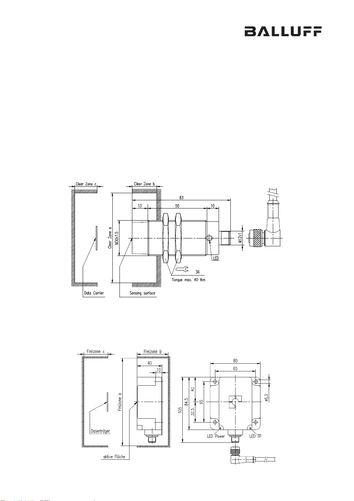
Installation notes
For proper operation at first a suitable mounting position has to be evaluated. The position
should respect the recommended clear zones as described. Furthermore, please note that
strong electrical or magnetic fields in the close environment may influence the RFID Reader.
Precise information concerning clear zones and distances are available on request.
For BF-IDM25 Readers are available in different housings respectively shapes different types of
installation may be considered.
a) Direct In-Hole mounting (Example):
Picture 2: Direct In-Hole mounting (Example)
b) Direct On-Wall mounting (Example):
Picture 3: Direct On-Wall mounting (Example)
Model:
BF-IDM25 Operating Guide
RFID Reader
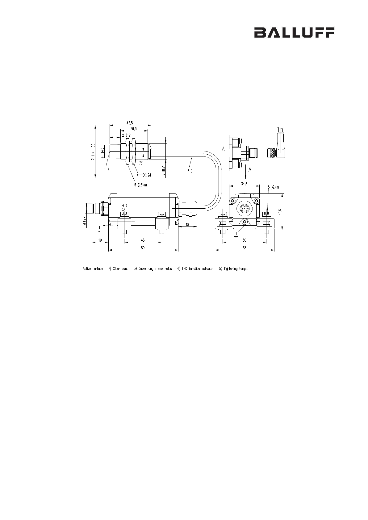
c) Indirect On-Wall mounting using metal holder (Example):
Picture 3: Indirect On-Wall mounting using metal holder (Example):

Model:
BF-IDM25 Operating Guide
RFID Reader
Setup and Operation
For operation of BF-IDM25 Readers a IO-Link Master device is needed. The Master is used as
gateway between higher level controllers and RFID Reader.
Status Indicators
The device will show its status using the 2 LEDs at the corners of the housing. In normal
operation state the meaning of these lights are as follows:
► Green light "Power" indicates that the device is connected to the processor unit and ready to
operate.
► Orange light "Tag present" indicates that a RFID tag has been detected in front of the
transceiver coil.
Electrical Data
Operating voltage (nominal)
+24 V DC
Current draw (at +24 V DC)
≤ 200 mA
Operating Frequency
13.56 MHz
Active principle
Magnetic field
Maximum transmit power
1 W
Mechanical Data
Housing Material
Metal / ABS-GF16 / PBT / PA12-GF30
Weight max.
400g
Ambient temperature
0…+70°C
 Loading...