

Page 1

AS-09(12)UR4SVNVG
SERVICE MANUAL
编号:XM00009562
编制:项目组长 李本卫
校对:电控 于心艳 张永良
结构 卢瑞艳
系统 李本卫
审核 1:
杜建伟
审核 2:
赵可可
审核 3: 殷显鑫
审核 4: 陆汉宁
批准:
王剑锋
海信科龙空调有限公司
2010 年 03 月
Page 2

Table of contents
Page
1.OPERATING RANGE 1
2.SPECIFICATION 2
2-1 Unit specifications 2
2-2 Major component specifications 3
2-3 Other component specifications 4
3.OUTLINES AND DIMENSIONS 6
3-1 INDOOR 6
3-2 OUTDOOR 7
4.REFRIGERANT FLOW DIAGRAM 8
4-1 Refrigerant flow diagram 8
4-2 Evacuation procedures 9
4-3 Evacuation direction 9
5.ELECTRICAL DATA 11
5-1 Electric wiring diagrams 11
5-2 Electric control 12
5-3 Sensor parameter 16
6.CONTROL MODE 18
6-1 control mode 18
7.TROUBLESHOOTING 26
7-1 Error codes 26
7-2 Service flow chart 28
8.CHECKING COMPONENTS 32
8-1 Check refrigerant system 32
8-2 Check parts unit 34
9.DISASSEMBLY INSTRUCTIONS 38
9-1 Indoor 38
Page 3

9-2 Outdoor 41
10.PARTS LIST 45
10-1 Indoor 45
10-2 Outdoor 47
Page 4

11.. OOPPEERRAATTIINNGG RRAANNGGE
E
AASS--0099((1122))UURR44SSVVNNVVGG
T emperature Indoor Air Intake T emp. Outdoor Air Intake T emp
Maximum
32℃ D.B./23℃ W.B. 43 ℃ D.B./26℃ W.B.
COOLING
Minimum
21℃ D.B./15℃ W.B. 21 ℃ D.B./15℃ W.B.
Maximum
27℃ D.B./18℃ W.B. 24℃ D.B./18℃ W.B.
HEATING
Minimum
20℃ D.B/≤15℃ W.B -7℃ D.B./-8℃ W.B.
1
Page 5
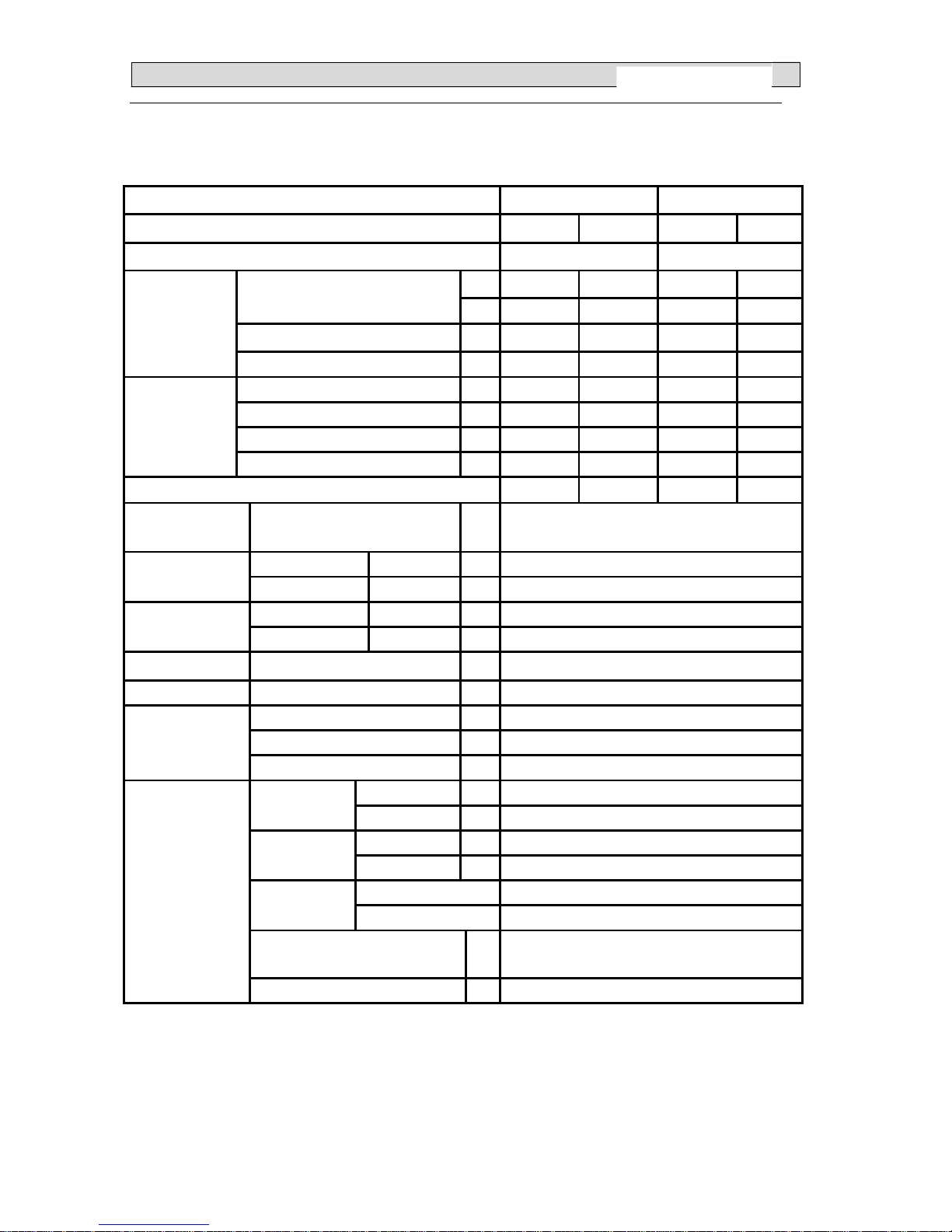
22.. SSPPEECCIIFFIICCAATTIIOONNSS
2-1. Unit specifications
NOTE :Test conditions:
Model
Function Cooling Heating Cooling Heating
Power supply a.c 220V/50Hz
BTU 9000 11000 11000 11500Capacity
kW 2.65 3.25 3.2 3.37
Dehumidification l /h 1.0
—-
1.0
—-
Capacity
Air flow m
3
/h
520 550 520 550
Rated current A 3.7 4.1 4.5 4.1
MAX. current A 8.0 10.0 8.0 10.0
Rated input kW 0.82 0.89 0.99 0.92
Electrical data
MAX. input kW 1.70 2.0 1.70 2.0
EER/COP 3.22 3.62 3.22 3.66
MAX.operating
pressure
High MP 4.15
Indoor unit
L×W×H
cm
75×19
×25
Net size
Outdoor unit
L×W×H
cm
72×24
×48
Indoor unit
L×W×H
cm
84×31
×27
Package size
Outdoor unit
L×W×H
cm
85×36
×53
Net weight Indoor unit / Outdoor unit kg 9.0/28.0
Gross weight Indoor unit / Outdoor unit kg 10.5/30.5
Liquid pipe mm 6.00
Gas pipe mm 9.52
Refrigerant
piping
Connection method Flared
Indoor unit dB 40 Sound level
(Hi)
Outdoor unit dB 52
Indoor unit rpm 1250 Fan speed
(Hi)
Outdoor unit rpm 880
Indoor unit 1 Fan speed
regulator
Outdoor unit 1
Refrigerant filling
capacity(R410A)
kg 0.72
Special
remarks
Throttle mode CAPILLARY( Shot T
ube Throttle Valve)
Cooling : Indoor: DB27℃/ WB19℃ Outdoor: DB35℃/ WB24℃
Heating: Indoor: DB20
℃/ WB15℃ Outdoor: DB7℃/ WB 6℃
2
BSGI 09 (12)
BSGI 09
BSGI 12
Page 6
22.. SSPPEECCIIFFIICCAATTIIOONNSS
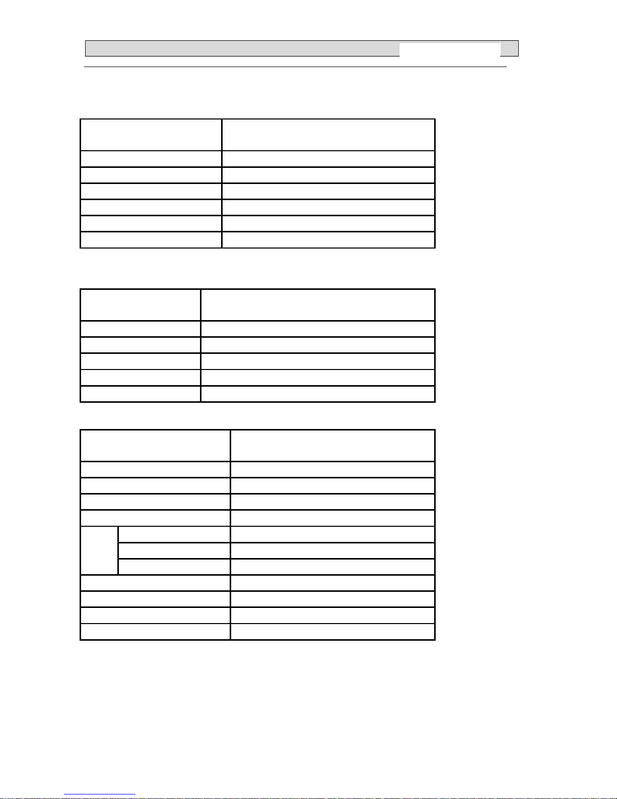
2-2. Major component specifications
2-2-1.INDOOR FAN MOTOR
ELECTRIC PERFORMANCE PARAMETER
Motor model RGP18
Rated power source 220V 50Hz
Phases/Poles 1/4
Rated load output(W) 16
Rated speed(r/min) 1330
Ambient temperature( )℃
-5℃~+43℃.
2-2-2 OUTDOOR FAN MOTOR
ELECTRIC
PERFORMANCE
PARAMETER
Motor model YDK29-6I-19
Rated power source 220V 50Hz
Phases /Poles 1/6
Rated load output(W) 28
Ambient temperature( )℃
-5℃~+43℃.
2-2-3. COMPRESSOR
ELECTRIC PERFORMANCE PARAMETER
Compressor model C-1RZ 089H 1E
Compressor type Rotary
Rated power 675W
Current (A) 4.20
Motor type DC brushless motor
Starting type DC Inverter
Motor
Winding resistance
0.744Ω
(at 25 )℃
Number of cylinder 1
Oil type FV50 B X
Oil charge (cc) 350
Ambient temperature( )℃
-7℃~
+43 .℃
3
BSGI 09(12)
Page 7
22.. SSPPEECCIIFFIICCAATTIIOONNSS
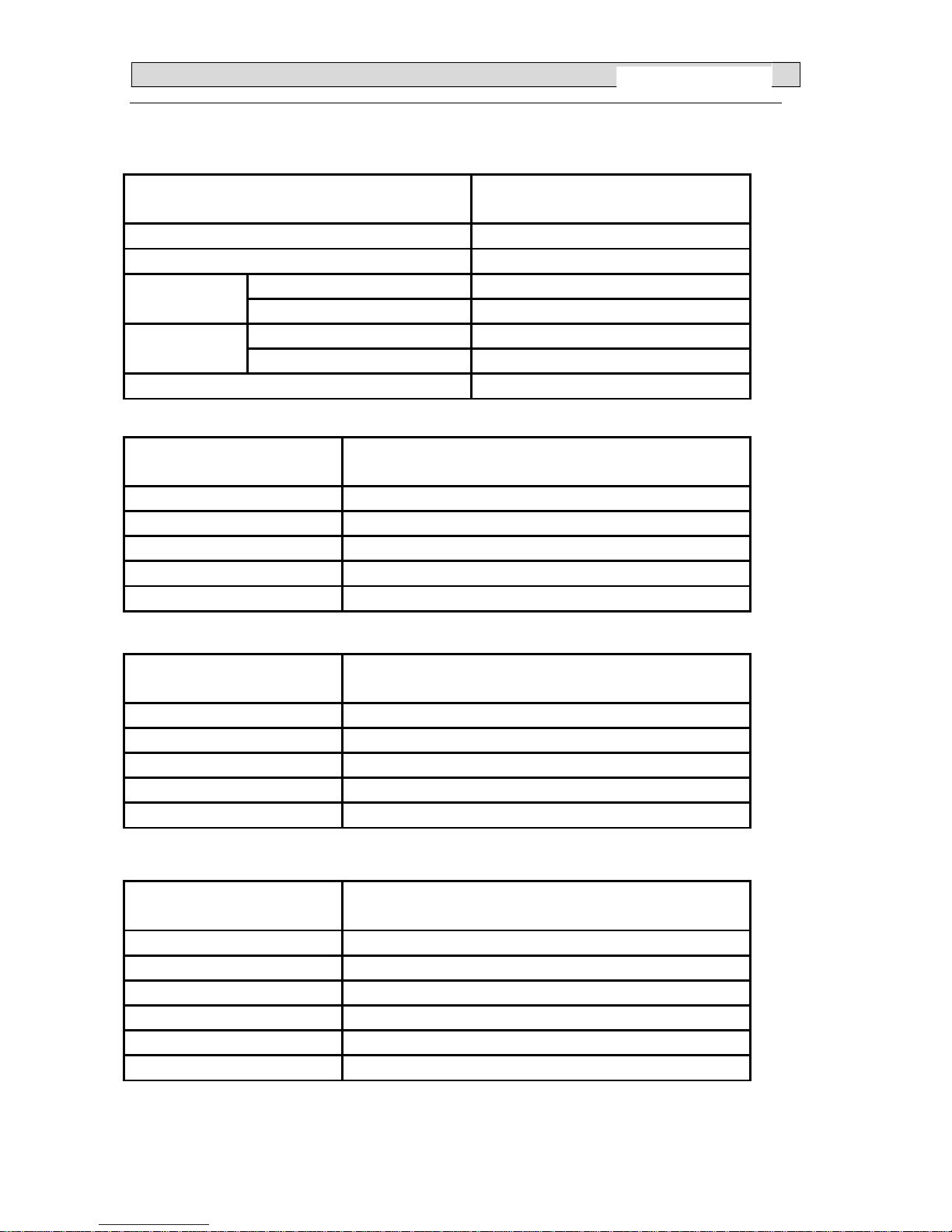
2-3. Other component specifications
2-3-1. INDUCTANCE
ELECTRIC PERFORMANCE PARAMETER
Inductance model Rated power source -
Loop winding rated current - Rated
current(A)
Filter winding rated current Loop winding rated inductance - Rated
inductance
(mH)
Filter winding rated inductance -
Ambient temperature( )℃ -
2-3-2. INDUCTANCE (1343046,A)
ELECTRIC PERFORMANCE PARAMETER
Inductance model R1250HSB
Rated power source 220V 50Hz
Rated current(A) 12
Rated inductance(mH) 5
Ambient temperature( )℃
-20℃~
+70 .℃
2-3-3. FILTER
ELECTRIC PERFORMANCE PARAMETER
Filter model RTLB-12T047-02JF
Rated current(A) 12
Rated power source 220V 50Hz
Filter frequency range 150K—30MHHz
Temperature range( )℃
-25℃~+85℃
.
2-3-4. STEPPER MOTOR
ELECTRIC PERFORMANCE PARAMETER
Stepper Motor model 24BYJ48
Voltage(DC) 12V
Number of phase 4
Drive mode 1-2phase excitation unipolar drive
Resistance per phase
200Ω
±7%
Temperature range( )℃
-10℃~
+40 .℃
4
BSGI 09(12)
Page 8

22.. SSPPEECCIIFFIICCAATTIIOONNSS
2-3-5. OVERLOAD PROTECTION
ELECTRIC
PERFORMANCE
PARAMETER
Model INT11L-3979
Reset temperature( )℃ 95±5℃
Trip temperature( )℃ 115±3℃
5
BSGI 09(12)
Page 9
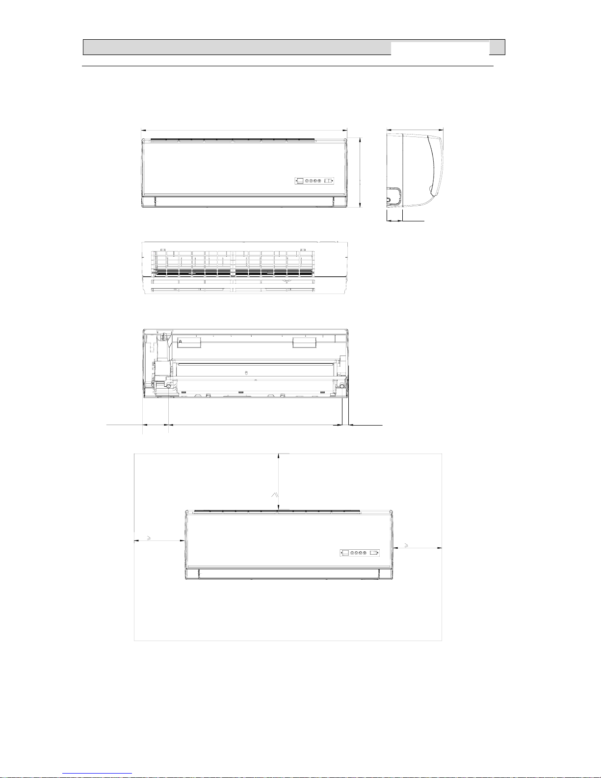
33.. OOUUTTLLIINNEESS AANNDD DDIIMMEENNSSIIOO
3-1. INDOOR
23mm631mm
94mm
750mm
65mm
250mm
190mm
50mm
50mm
50mm
3-2.OUTDOOR
6
BSGI 09(12)
Page 10
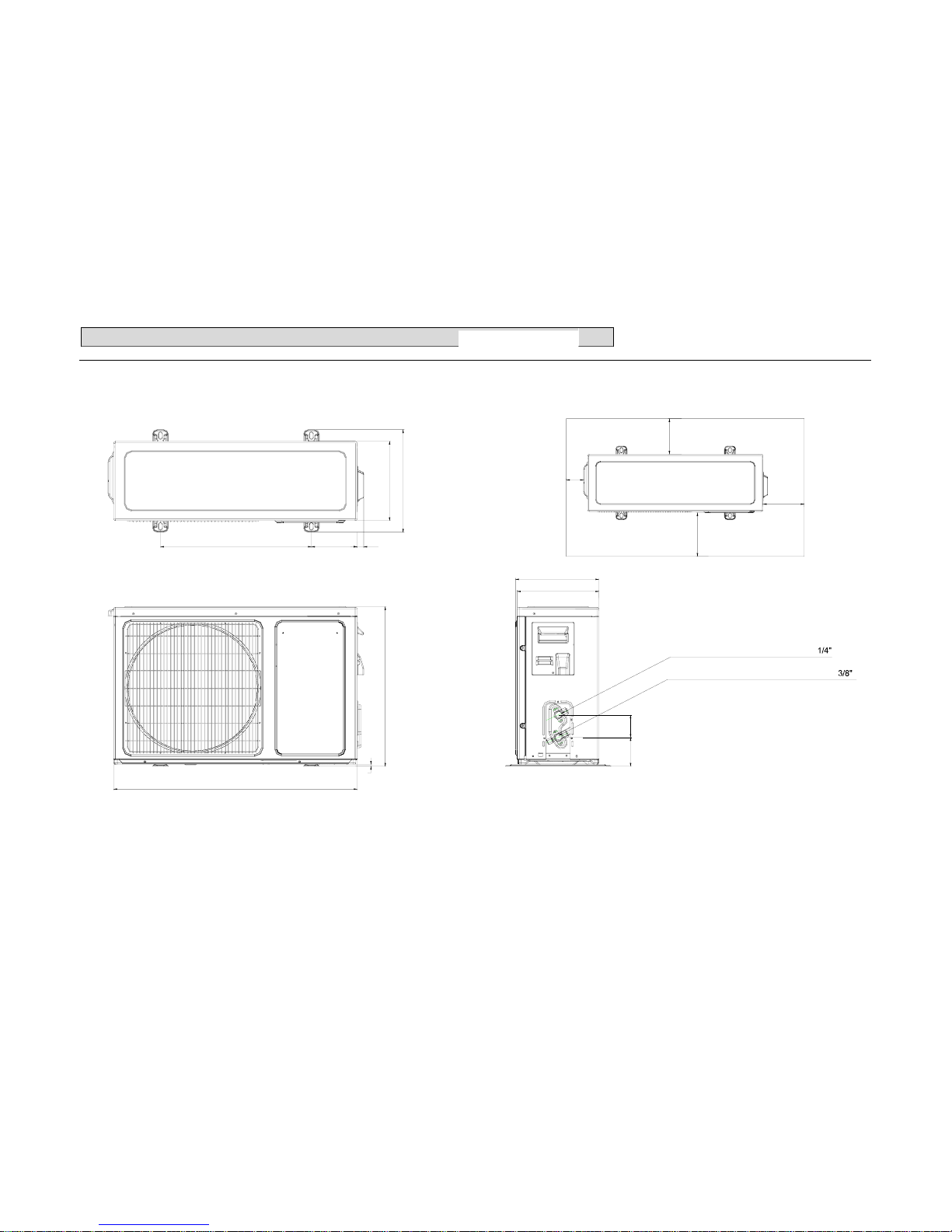
33.. OOUUTTLLIINNEESS AANNDD DDIIMMEENNSSIIOO
443
240
245
240
6
715
482
310
134.5 19
NARROW TUBE SERVICE VALVE Φ9.52 ( )
WIDE TUBE SERVICE VALVE
Φ6.0( )
6887
>40cm
>25cm
>10cm
>5cm
7
BSGI 09(12)
Page 11
44.. RREEFFRRIIGGEERRAANNTT FFLLOOWW DDIIAAGGRRAAM
M
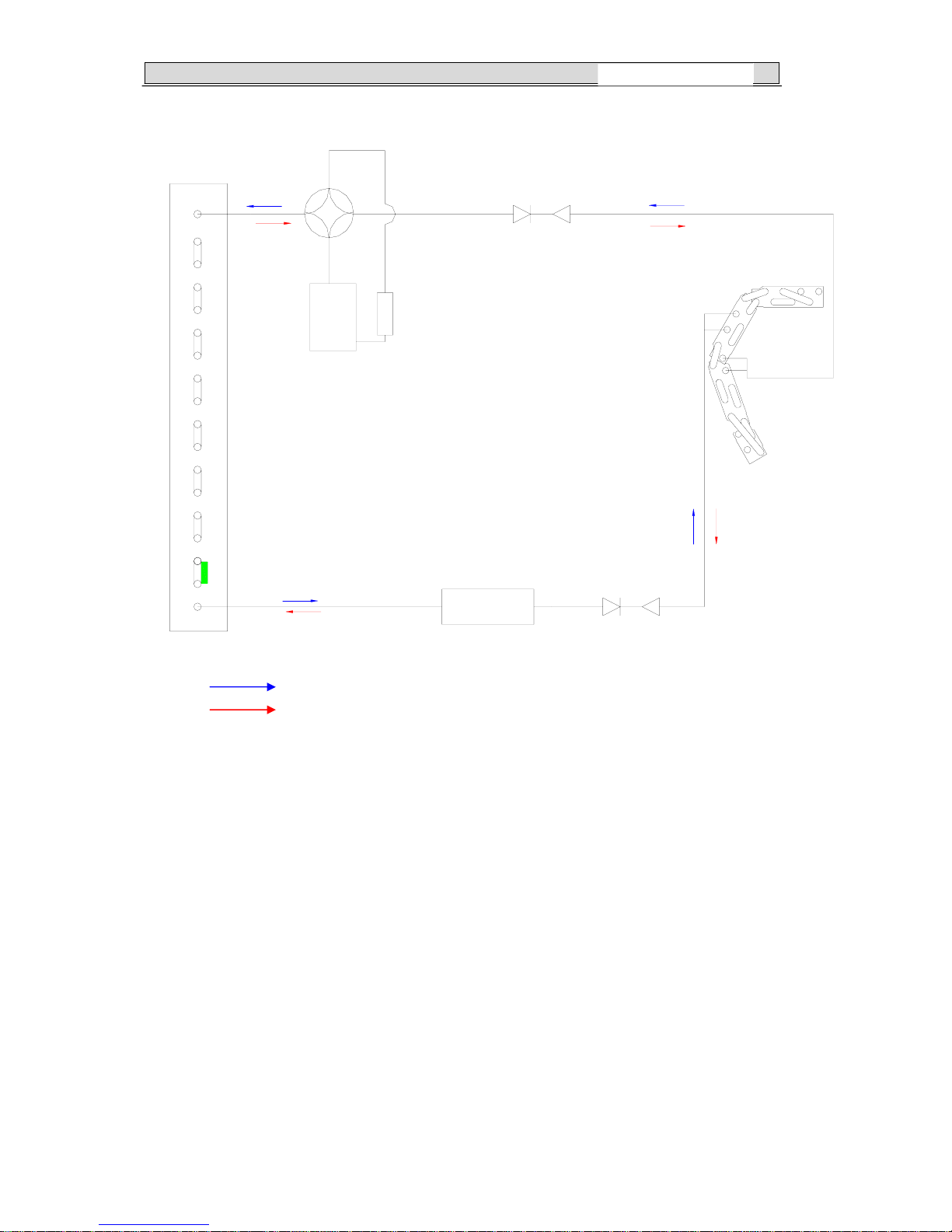
4-1. Refrigerant flow diagram :
INDOOROUTDOOR
EVAPORATOR
CONDENSER
CHECK VALVE ASS'Y
COMPRESSOR
CAPILLARY(Shot Tube
Throttle Valve )
Remark: COOLING CYCLE
Remark: HEATING CYCLE
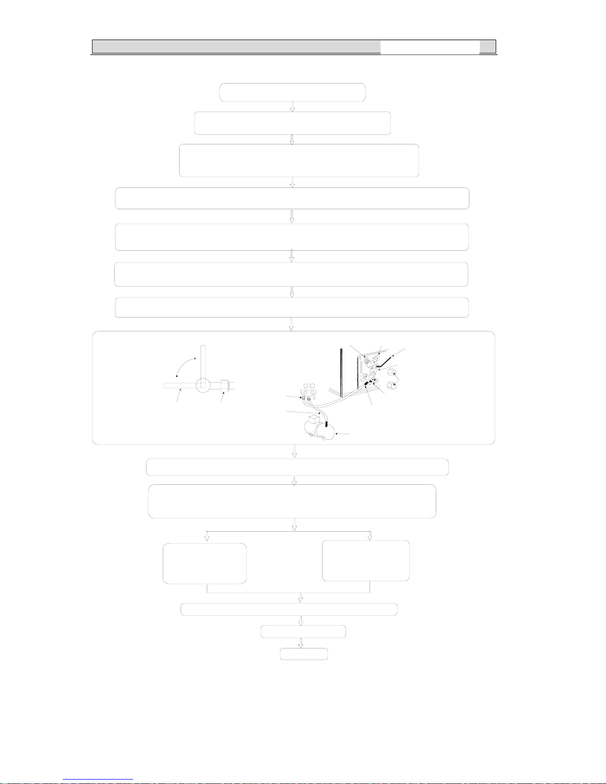
4-2. Evacuation procedures:
8
BSGI 09(12)
Page 12
44.. RREEFFRRIIGGEERRAANNTT FFLLOOWW DDIIAAGGRRAAM
M
EVACUATION PROCEDURES
Connect the r efriger ant pi pes (both the l iquid and gas
pipes) between the indoor and the outdoor units.
Remove the service port cap of the stop valve on the side of the
outdoor unit gas pipe. ( The stop valve will not work in its initial
state fresh out of the factory (totally closed with cap on).
Connect the gage manifold valve and the vacuum pump to the service port of the stop valve on
the gas pipe side of the outdoor unit.
Run the vacuum pump for more than 15 minutes and at this time confirm that the pressure gage
indicates -0.1 Mpa (-76 cmHg).
Check the vacuum with the gage manifold valve, then close the gage manifold valve, and stop the
vacuum pump.
Leave it as is for one or two minutes .Make sure the pointer of the gage manifold valve remains
in the same position.
Close
Open
Hexagonal
wrench
Stop valve
pipe
Connection
Gage manifold valve
Stop valve
Liquid pipe
Stop valve
Hexagonal wrench
Gas pipe
Caps
Service port
Vacuum pump
Remove the gage man ifold valve qu ickly from th e service po rt of the stop valve.
After refrigerant pipes are connected and evacuated, fully open all stop valves
on gas and liquid pipe sides.
Operating without fully opening lowers the performance and causes trouble.
Pipe length
7m maximum
No gas charge is
needed.
Pipe length
exceeding 7m
Charge the prescribed
amount of gas.
Tighten the cap to the service port to obtain the initial status.
Retighten the cap.
Leak test
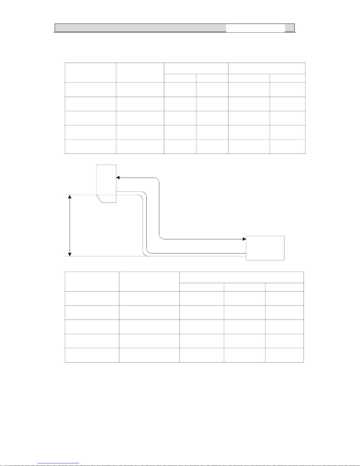
4-3. Evacuation direction:
9
BSGI 09(12)
Page 13
44.. RREEFFRRIIGGEERRAANNTT FFLLOOWW DDIIAAGGRRAAM
M
MAX. REFRIGER ANT PIPING LENGTH
Models
Refrigerant Piping
Max. Length: m
A
Piping size (OD) : mm Length of connecting pipe : m
Gas
Liquid Indoor unit
Outdoor unit
Models
Indoor
unit
Outdoor unit
MAX. HEIGHT DIFFERENCE
Outdoor unit precharged
(up to 7m)
Refrigerant piping length
15m7m
Max. Height
difference 7m
Refrigerant piping
Max. Length
A
ADDITIONAL: R EFRIGERANT CHARGE(R-410A: g)
AS 09(12)UR4SVNZC
-
15 9 52
.
6.00
720
75
0
Canculation :Xg=25g/m*(A-7)m
10m
200
AS 09(12)UR4SVNZC
-
10
BSGI 09(12)
Page 14
55.. EELLEECCTTRRIICCAALL DDAATTAA
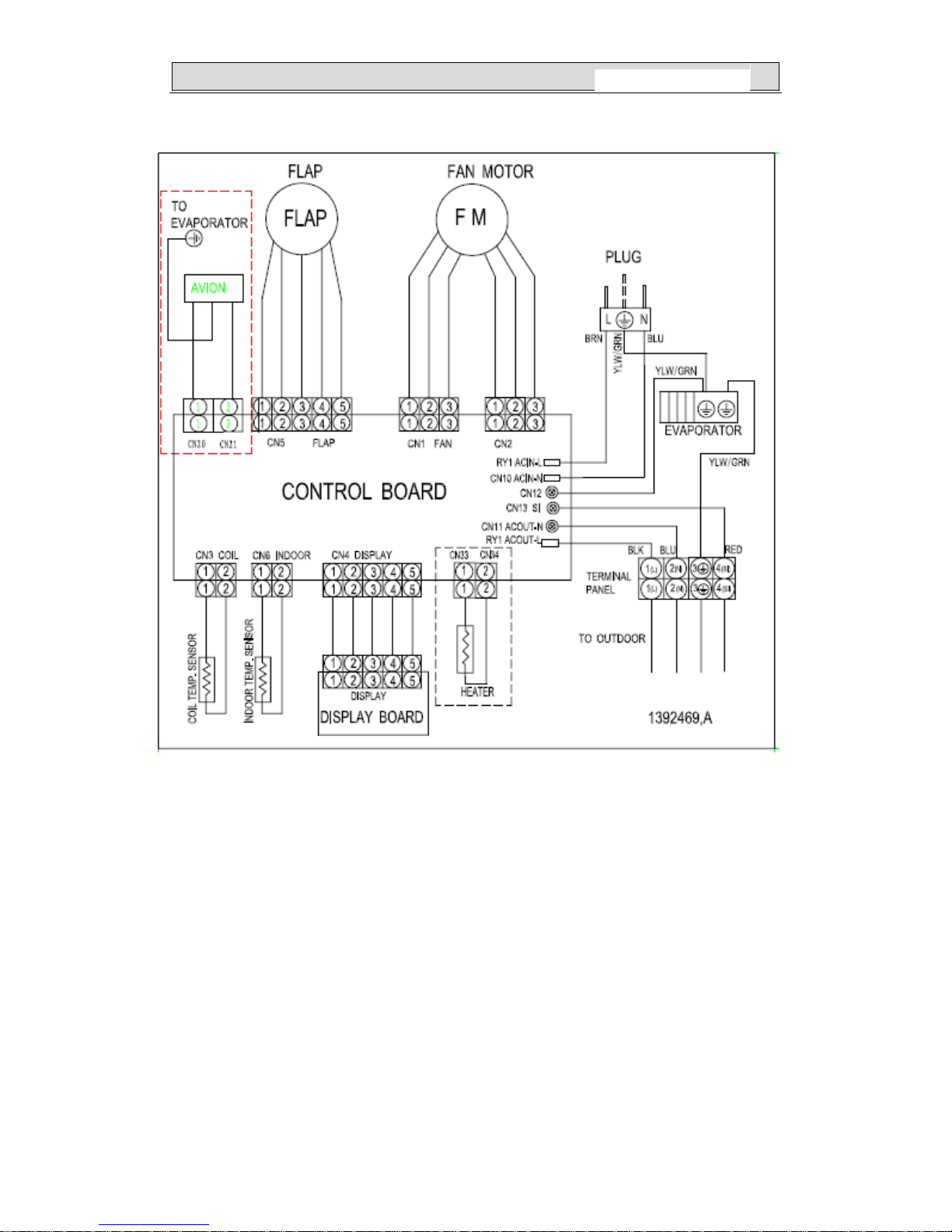
5-1.Electrical wiring diagrams
1.INDOOR
11
BSGI 09(12)
Page 15
55.. EELLEECCTTRRIICCAALL DDAATTAA
12
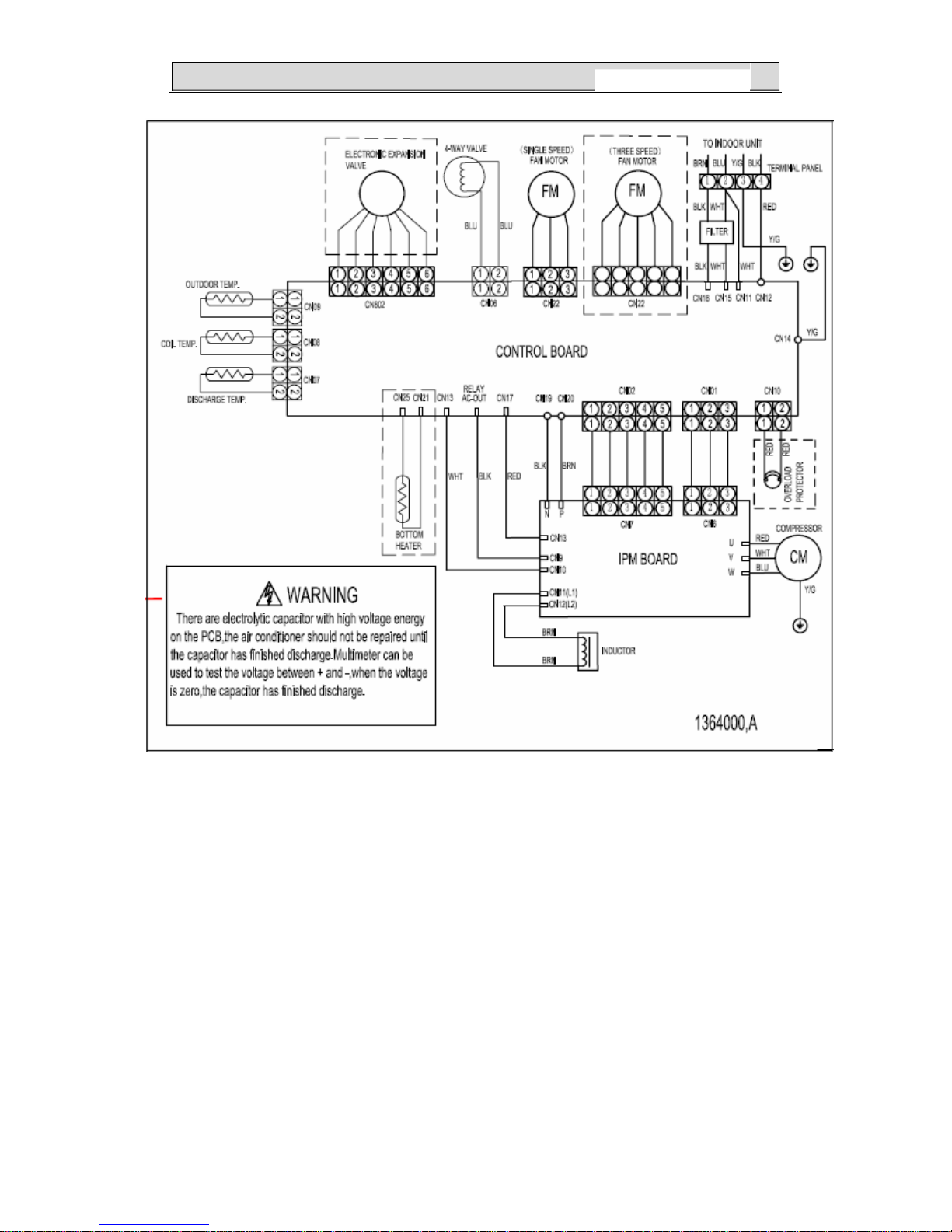
2.OUTDOOR
5-2. Electric control
1.Indoor control
BSGI 09(12)
Page 16
55.. EELLEECCTTRRIICCAALL DDAATTAA
13
2.Outdoor control
BSGI 09(12)
Page 17

55.. EELLEECCTTRRIICCAALL DDAATTAA
14
OUT IPM:
BSGI 09(12)
Page 18

55.. EELLEECCTTRRIICCAALL DDAATTAA
15
BSGI 09(12)
Page 19

55.. EELLEECCTTRRIICCAALL DDAATTAA
1. THE PARAMETER OF OUTDOOR COMPRESSOR TEMPERATURE SENSOR:
(R0=187.25K±6.3%;R
100
=3.77K±2.5K;B=3979±1%)
T(℃) R(KΩ) V(v) DEC HEX T(℃) R(KΩ) V(v) DEC HEX T(℃) R(KΩ) V(v) DEC HEX
-30 966.1 0.1014 5 5 26 55.46 1.3252 68 44 82 6.662 3.7507 191
BF
-29 910.3 0.1075 5 5 27 53.11 1.3678 70 46 83 6.446 3.7813 193
C1
-28 858 0.1139 6 6 28 50.86 1.4112 72 48 84 6.239 3.8111 194
C2
-27 809 0.1206 6 6 29 48.72 1.4552 74
4A
85 6.039 3.8404 196
C4
-26 763.1 0.1277 7 7 30 46.68 1.4997 76
4C
86 5.846 3.8691 197
C5
-25 720 0.1351 7 7 31 44.74 1.5446 79
4F
87 5.661 3.8970 199
C7
-24 679.6 0.1429 7 7 32 42.89 1.5901 81 51 88 5.482 3.9243 200
C8
-23 641.7 0.1511 8 8 33 41.13 1.6359 83 53 89 5.309 3.9512 202
CA
-22 606.1 0.1597 8 8 34 39.44 1.6824 86 56 90 5.143 3.9773 203
CB
-21 572.7 0.1687 9 9 35 37.84 1.7289 88 58 91 4.982 4.0029 204
CC
-20 541.3 0.1782 9 9 36 36.3 1.7762 91
5B
92 4.827 4.0279 205
CD
-19 511.7 0.1881 10
A
37 34.84 1.8235 93
5E
93 4.678 4.0522 207
CF
-18 484 0.1984 10
A
38 33.44 1.8713 95
5F
94 4.534 4.0760 208
D0
-17 457.9 0.2092 11
B
39 32.11 1.9190 98 62 95 4.395 4.0992 209
D1
-16 433.3 0.2206 11
B
40 30.83 1.9673 100 64 96 4.261 4.1218 210
D2
-15 410.2 0.2325 12
C
41 29.61 2.0157 103 67 97 4.132 4.1439 211
D3
-14 388.5 0.2448 12
C
42 28.45 2.0640 105 69 98 4.007 4.1655 212
D4
-13 368 0.2577 13
D
43 27.34 2.1124 108
6C
99 3.886 4.1866 214
D6
-12 348.7 0.2712 14
E
44 26.27 2.1612 110
6E
100 3.77 4.2070 215
D7
-11 330.5 0.2853 15
F
45 25.25 2.2099 113 71 101 3.658 4.2269 216
D8
-10 313.4 0.2999 15
F
46 24.28 2.2584 115 73 102 3.549 4.2465 217
D9
-9 297.2 0.3153 16 10 47 23.35 2.3068 118 76 103 3.444 4.2655 218
DA
-8 281.9 0.3312 17 11 48 22.46 2.3552 120 78 104 3.343 4.2839 218
DA
-7 267.5 0.3478 18 12 49 21.6 2.4038 123
7B
105 3.15 4.3197 220
DC
-6 253.9 0.3651 19 13 50 20.79 2.4516 125
7D
106 3.059 4.3367 221
DD
-5 241.1 0.3830 20 14 51 20.01 2.4994 127
7F
107 2.97 4.3535 222
DE
-4 229 0.4016 20 14 52 19.26 2.5471 130 82 108 2.884 4.3699 223
DF
-3 217.6 0.4209 21 15 53 18.54 2.5947 132 84 109 2.802 4.3856 224
E0
-2 206.8 0.4409 22 16 54 17.85 2.6420 135 87 110 2.721 4.4012 224
E0
-1 196.6 0.4617 24 17 55 17.19 2.6889 137 89 111 2.721 4.4012 224
E0
0 186.9 0.4833 25 18 56 16.56 2.7352 139
8B
112 2.644 4.4162 225
E1
1 177.8 0.5056 26 19 57 15.96 2.7809 142
8E
113 2.569 4.4309 226
E2
2 169.2 0.5285 27
1A
58 15.38 2.8265 144 90 114 2.496 4.4452 227
E3
3 161 0.5525 28
1B
59 14.82 2.8719 146 92 115 2.426 4.4591 227
E3
4 153.3 0.5770 29
1C
60 14.29 2.9163 149 95 116 2.358 4.4727 228
E4
5 146 0.6024 31
1E
61 13.78 2.9603 151 97 117 2.292 4.4859 229
E5
6 139 0.6289 32
1F
62 13.28 3.0048 153 99 118 2.228 4.4988 229
E5
7 132.5 0.6557 33 21 63 12.81 3.0479 155
9B
119 2.167 4.5112 230
E6
8 126.3 0.6835 35 23 64 12.36 3.0902 158
9E
120 2.107 4.5235 231
E7
9 120.4 0.7123 36 24 65 11.93 3.1319 160
A0
121 2.049 4.5354 231
E7
10 114.8 0.7418 38 26 66 11.51 3.1736 162
A2
122 2.049 4.5354 231
E7
11 109.5 0.7722 39 27 67 11.11 3.2144 164
A4
123 1.994 4.5467 232
E8
12 104.4 0.8039 41 29 68 10.73 3.2541 166
A6
124 1.887 4.5689 233
E9
13 99.66 0.8357 43
2B
69 10.36 3.2938 168
A8
125 1.836 4.5796 234
EA
14 95.13 0.8686 44
2D
70 10 3.3333 170
AA
126 1.787 4.5899 234
EA
15 90.82 0.9024 46
2C
71 9.659 3.3717 172
AC
127 1.739 4.6000 235
EB
16 86.74 0.9369 48
2E
72 9.331 3.4094 174
AE
128 1.693 4.6098 235
EB
17 82.85 0.9723 50 32 73 9.016 3.4464 176
B0
129 1.649 4.6192 236
EC
18 79.16 1.0085 51 33 74 8.712 3.4829 178
B2
130 1.605 4.6286 236
EC
19 75.65 1.0455 53 35 75 8.421 3.5185 179
B3
20 72.32 1.0832 55 37 76 8.14 3.5537 181
B5
21 69.15 1.1217 57 39 77 7.869 3.5882 183
B7
22 66.13 1.1610 59
3B
78 7.609 3.6220 185
B9
23 63.27 1.2009 61
3D
79 7.359 3.6551 186
BA
24 60.54 1.2416 63
3F 80
7.118 3.6876 188
BC
25 57.94 1.2830 65 41 81 6.885 3.7195 190
BE
16
BSGI 09(12)
Page 20

55.. EELLEECCTTRRIICCAALL DDAATTAA
2. THE PARAMETER OF THE COIL AND INDOOR AND OUTDOOR SENSOR:
(R
0
=15K±2%;B=3450±2%)
T(℃) R(KΩ) V(v) DEC HEX T(℃) R(KΩ) V(v) DEC HEX T(℃) R(KΩ) V(v) DEC HEX
-30 67.94 0.3235 16 10 18 6.962 2.0151 103 67 66 1.297 3.9186 200 C8
-29 64.25 0.3408 17 11 19 6.688 2.0636 105 69 67 1.258 3.9443 201 C9
-28 60.79 0.3588 18 12 20 6.427 2.1120 108 6C 68 1.22 3.9696 202 CA
-27 57.53 0.3776 19 13 21 6.178 2.1603 110 6E 69 1.184 3.9939 204 CC
-26 54.48 0.3971 20 14 22 5.939 2.2089 113 71 70 1.149 4.0178 205 CD
-25 51.6 0.4174 21 15 23 5.712 2.2570 115 73 71 1.116 4.0406 206 CE
-24 48.9 0.4384 22 16 24 5.494 2.3053 118 76 72 1.083 4.0636 207 CF
-23 46.35 0.4603 23 17 25 5.286 2.3533 120 78 73 1.051 4.0862 208 D0
-22 43.96 0.4829 25 19 26 5.086 2.4014 122 7A 74 1.021 4.1077 209 D1
-21 41.7 0.5065 26 1A 27 4.896 2.4489 125 7D 75 0.9914 4.1290 211 D3
-20 39.58 0.5307 27 1B 28 4.714 2.4963 127 7F 76 0.963 4.1497 212 D4
-19 37.58 0.5558 28 1C 29 4.539 2.5436 130 82 77 0.9354 4.1701 213 D5
-18 35.69 0.5818 30 1E 30 4.372 2.5904 132 84 78 0.9088 4.1898 214 D6
-17 33.91 0.6087 31 1F 31 4.212 2.6369 134 86 79 0.8831 4.2091 215 D7
-16 32.23 0.6363 32 20 32 4.059 2.6830 137 89 80 0.8582 4.2280 216 D8
-15 30.65 0.6648 34 22 33 3.912 2.7288 139 8B 81 0.8342 4.2463 217 D9
-14 29.15 0.6942 35 23 34 3.772 2.7738 141 8D 82 0.8109 4.2643 217 D9
-13 27.74 0.7244 37 25 35 3.637 2.8188 144 90 83 0.7884 4.2818 218 DA
-12 26.4 0.7556 39 27 36 3.508 2.8631 146 92 84 0.7666 4.2988 219 DB
-11 25.14 0.7875 40 28 37 3.384 2.9070 148 94 85 0.7455 4.3155 220 DC
-10 23.95 0.8202 42 2A 38 3.265 2.9504 150 96 86 0.725 4.3318 221 DD
-9 22.82 0.8539 44 2C 39 3.151 2.9932 153 99 87 0.7053 4.3476 222 DE
-8 21.75 0.8885 45 2D 40 3.041 3.0358 155 9B 88 0.6861 4.3631 223 DF
-7 20.74 0.9237 47 2F 41 2.936 3.0775 157 9D 89 0.6676 4.3781 223 DF
-6 19.79 0.9596 49 31 42 2.835 3.1188 159 9F 90 0.6496 4.3929 224 E0
-5 18.88 0.9966 51 33 43 2.739 3.1590 161 A1 91 0.6323 4.4071 225 E1
-4 18.02 1.0343 53 35 44 2.646 3.1990 163 A3 92 0.6156 4.4209 225 E1
-3 17.2 1.0731 55 37 45 2.556 3.2387 165 A5 93 0.5993 4.4345 226 E2
-2 16.43 1.1122 57 39 46 2.471 3.2771 167 A7 94 0.5836 4.4477 227 E3
-1 15.7 1.1520 59 3B 47 2.388 3.3155 169 A9 95 0.5683 4.4606 227 E3
0 15 1.1929 61 3D 48 2.309 3.3528 171 AB 96 0.5535 4.4732 228 E4
1 14.34 1.2342 63 3F 49 2.233 3.3896 173 AD 97 0.5391 4.4855 229 E5
2 13.71 1.2765 65 41 50 2.159 3.4262 175 AF 98 0.5251 4.4975 229 E5
3 13.11 1.3195 67 43 51 2.089 3.4615 177 B1 99 0.5115 4.5093 230 E6
4 12.55 1.3623 69 45 52 2.021 3.4965 178 B2 100 0.4983 4.5207 231 E7
5 12.01 1.4063 72 48 53 1.956 3.5306 180 B4 101 0.4855 4.5319 231 E7
6 11.5 1.4506 74 4A 54 1.893 3.5644 182 B6 102 0.4731 4.5427 232 E8
7 11.01 1.4959 76 4C 55 1.832 3.5977 183 B7 103 0.461 4.5534 232 E8
8 10.55 1.5410 79 4F 56 1.774 3.6299 185 B9 104 0.4492 4.5638 233 E9
9 10.1 1.5878 81 51 57 1.718 3.6616 187 BB 105 0.4378 4.5739 233 E9
10 9.684 1.6338 83 53 58 1.664 3.6926 188 BC 106 0.4268 4.5838 234 EA
11 9.284 1.6805 86 56 59 1.612 3.7231 190 BE 107 0.416 4.5934 234 EA
12 8.903 1.7276 88 58 60 1.562 3.7528 191 BF 108 0.4055 4.6029 235 EB
13 8.54 1.7749 91 5B 61 1.513 3.7824 193 C1 109 0.3953 4.6121 235 EB
14 8.194 1.8226 93 5D 62 1.467 3.8106 194 C2 110 0.3854 4.6211 236 EC
15 7.864 1.8704 95 5F 63 1.422 3.8386 196 C4
16 7.549 1.9185 98 62 64 1.379 3.8658 197 C5
17 7.249 1.9667 100 64 65 1.337 3.8927 199 C7
17
BSGI 09(12)
Page 21

66.. CCOONNTTRROOLL MMOODDEEL
L
6-1. Major general technical parameters
6-1-1 Conditionings for operation: Ambient temperatures: (-15 - +45
℃), relative humidity (45 -
85%).
6-1-2 Remote receiver distance: 8 m.
6-1-3 Remote receiver angle: Less than 80 degrees.
6-1-4 Temperature control accuracy: ±1℃.
6-1-5 Time error: Less than 1%.
6-1-6 The power supply for the air conditioner is a.c 220V
, 50Hz, with its fluctuation in the
range of (198~264V).
6-2. Functions of the controller
6-2-1 Display panel
I. Control functions of the remote controller (See op
erating and installation manual)
II. Display of the indoor unit
Information on the screen:
The picture of the display i
s as follows:
Displaying Scheme:
T emperature display:Display set temperatu
re or indoor temperature , and display fault code
in trouble indicating. An error code is displayed according to the signal from the indoor CPU.
The error code will flash for 5 seconds while displayed.
Running indicator:It is on during oper
ation. It flashes in 10s after the sleep modehas been
setted.
TIMER indicator:When
the timer mode works, the indicator will be lighted.
Sleep indicator:When the sleep mode works, th
e indicator will be lighted.
Compressor indicator:It
lights up when compressor is running.
Remote control receiver: This
section receives signals from the remote controller.
6-3. Control function
6-3-1 Emergency switch
6-3-1-1 Press the emergency switch once to turn o
n the machine and press it again to turn off
the machine; in the automatic mode, the indoor control temperature is set at 24℃ with the
indoor fan speed setting is automatic and the flaps sweep.
6-3-1-2 When the machine is turned on (in the OFF condition),
press and hold the emergency
18
BSGI 09(12)
Page 22

66.. CCOONNTTRROOLL MMOODDEEL
L
switch for 5 seconds, the buzzer rings for 3 times and the controller starts in the trial operation.
The trial operation is the forced cooling with the indoor fan speed being set at high speeds,
the flaps sweeping and the air conditioner’s operation is irrelevant with room temperatures.
6-3-1-3 If a remote signal has been received during the emergency run, the ma
chine will
operate upon the command of such a remote signal.
6-3-2 Operator-machine communication
6-3-2-1 The air conditioner has a thermal sensor to detect room temperatures. Some remote
controller is
equipped with a thermal sensor (Such remote controller has the function of
man-machine communication. For details, refer to the section for the remote controller). In
addition, there is a thermal sensor at the indoor air inlet. In the case where the remote
controller is equipped with a thermal sensor, the default setting for room temperatures is
subject to the detection by the remote controller. The remote controller detects the room
temperature once every 20 seconds, and automatically transmits a signal at an interval of 3
minutes or when a change in the room temperature is detected. If the indoor control unit has
not received a remote signal for more than 10 minutes, the control function will be
automatically switched over to the thermal sensor on the indoor unit.
6-3-2-2 Neither the turning on nor turning of
f operation will cancel the operator-machine
communication function.
6-3-2-3 In default, the air conditioner is set to st
art the operator-machine communication
function.
6-3-3 Timer function
6-3-3-1 Timer on: When set to start in a time by the remote controller
, the air conditioner starts
in the timer on condition. When the set time is up, the air conditioner will turn on and operates
in the preset conditions after receiving a signal from the remote controller. If the air conditioner
has not received a signal from the remote controller when the set time is up, it will
automatically start and operate in the preset conditions.
6-3-3-2 Timer off: When set to stop in a set time by the remote controller, the air conditioner
will start in the timer off condition. When the set time is up, the air conditioner will turn off after
19
BSGI 09(12)
Page 23

66.. CCOONNTTRROOLL MMOODDEEL
L
receiving a signal from the remote controller. If the air conditioner has not received a signal
from the remote controller when the set time is up, it will turn off automatically.
6-3-3-3 Neither the turning on nor turning off operation will cancel the tim
er function (Some
remote controller has a simple one-hour timer off function and excludes this operation).
6-3-4 Sleep
6-3-4-1 In the heating, cooling or dehumidifying mo
de, press the “Sleep” button on the remote
controller to start or cancel the sleep function in turn, and at the same time the sleep icon on
the display screen will be on or off accordingly.
6-3-4-2 According to the different needs, there are four dif
ferent sleep modes to choose.
During the time of sleep mode, the set temperature will change automatically.
6-3-4-3 In default, the setting is to cancel the sleep function. Turning off the unit will also
cancel the sleep function.
6-3-4-4 The sleep function is valid for 8 hours. The air condition
er will turns off and cancel the
sleep function after the sleep function works for 8 hours.
6-3-5 High efficient run function (This function is invalid)
In the heating (except for the single cooling unit), cooling o
r dehumidifying mode, it may be set
for high efficient run with the indoor fan speed changed to the high efficient fan speed and the
compressor operating at the highest frequency as available. If the display screen can display
the frequency, the frequency displayed on the screen is up to the maximum. It will restore to
the previous run state after 15 minutes operation automatically.
6-3-6 Automatic run (SMART) mode
If there is no man-machine communication function af
ter the unit is started, the indoor fan
operates at the ultra-low flowrate for 20 seconds before selecting a run mode; the room
temperatures are detected during this period for the selection of a run mode.
In the first operation:
a. When
T
room
– T
set
>3℃, it starts in the cooling mode;
b.
When -3℃≤T
room
– T
set
≤3℃, it starts in the ventilation run mode;
c. When
T
room
– T
set
<-3℃, it starts in the heating mode.
After the first run in the cooling or heating mode, the mode will be changed as the following:
20
BSGI 09(12)
Page 24

66.. CCOONNTTRROOLL MMOODDEEL
L
a. When T
room
– T
set
>3℃, it will be changed to the cooling mode;
b. When
T
room
– T
set
<-3℃, it will be changed to the heating mode;
c.
When these conditions are not met, it will remain in the previous run mode.
When the temperature setting is changed, re-judgment will be made
for the run mode
according to the descriptions mentioned above; when the compressor is halted for 10 minutes,
the re-judgment will be made for the run mode.
6-3-6-1 Switch between the cooling a
nd heating mode:
T
ambient
t
set
+3
t
set
t
set
-3
Cooling Heating mode Cooling
6-3-6-2 Cooling→heating turnover
operation
Cooling→h
eating: the compressor stops; 50 s later the 4-way valve is activated and 3 minutes
more the compressor turns on.
Heating→co
oling: the compressor stops, 50 s later the 4-way valve is interrupted and 3
minutes more the compressor turns on.
6-3-6-3 There is temperature compensation during the auto-run, which is same as cooling and
heating.
6-3-7 Cooling-run mode
6-3-7-1 Temperature compensation
Principle for compensation: The compensation is available o
nly if the proper sensor is used
and it is not available when it is subject to the sensor on the remote controller.
6-3-7-2 Outdoor Fan
The outdoor fan’s speeds are divided into two levels which can be changed over according to
out
door ambient temperatures.
When operating at a fixed frequency, the outdoor fan is forced to operate at the high speed.
6-3-7-3 Indoor fan
When the fan speed is set at the high, medium a
nd low fan speeds, the fan runs at a preset
speed. When the fan speed setting is automatic, the fan speed is set based on the difference
in room temperatures.
21
BSGI 09(12)
Page 25

66.. CCOONNTTRROOLL MMOODDEEL
L
T
room-Tset
Indoor fan speed
T
room-Tset
≤20C
Low
20C <T
room-Tset
<40C
Medium
T
room-Tset
≥40C
High
6-3-7-4 Prevention against condensation and insuf
ficient heat exchange at the low indoor fan
speed.
When the indoor fan speed is set at the low fan spe
ed, the compressor’s power is restricted as
in the low temperature cooling.
6-3-7-5 4-way valve
State: It is interru
pted in cooling.
Switchover: When initially powered on for cooling, the 4-way valve is interrupted immediately.
When the heating is changed to the cooling, it nee
ds an interval of 50 seconds for the 4-way
valve to change over from being activated to being interrupted.
6-3-8 Heating-run mode
6-3-8-1 Temperature compensation
Principle for compensation: The compensation is available only if the prope
r sensor is used
and it is not available when it is subject to the sensor on the remote controller or line controller.
6-3-8-2 Indoor fan
The fan speed is set at the high, medium or low fan speed, it operates at
a preset speed (in
the cold air prevention, it is forced to run at the ultra-low flowrate or stop).
When the fan speed is set in the auto-r
un, the fan speed setting is made according to the room
temperature differences (except for the cold air prevention).
T
set-Troom
Indoor Fan Speed
T
set-Troom
≤20C
Low
20C <T
set-Troom
<40C
Medium
T
set-Troom
≥40C
High
6-3-8-3 Cold air prevention
In the heating-run, to prevent the indoor fan from blowing cold
air, the indoor fan speed is
different from the set speed after turning on air-conditioner.
6-3-8-4 Residual heat blowing off
22
BSGI 09(12)
Page 26

66.. CCOONNTTRROOLL MMOODDEEL
L
When the compressor is turned off in the heating run, the indoor fan does not stop at once, but
until the indoor evaporator temperature is below 23
0
C, but for 30 seconds at the latest.
When the compressor is turned off in the heating run, the indoor fan does not stop at once, but
until the indoor evaporator temperature is below 230C, but for 30 seconds at the latest.
6-3-8-5 Outdoor fan 6-3-8-5 Outdoor fan
The outdoor fan speeds are divided into three level
s which can be changed over according to
outdoor ambient temperatures.
The outdoor fan speeds are divided into three levels which can be changed over according to
outdoor ambient temperatures.
6-3-8-6 4-way valve 6-3-8-6 4-way valve
State: It is electrified in h
eating. State: It is electrified in heating.
Switchover: When initially powered on for heating, the 4-way valve is activated immediately
. Switchover: When initially powered on for heating, the 4-way valve is activated immediately.
In the change from cooling to heating, it needs an interval of 50 seconds for the 4-way valve to
change o
ver from being interrupted to being activated.
In the change from cooling to heating, it needs an interval of 50 seconds for the 4-way valve to
change over from being interrupted to being activated.
6-3-9 Dehumidifying mode 6-3-9 Dehumidifying mode
The dehumidifying mode is illustrated as follows: The dehumidifying mode is illustrated as follows:
Indoor Ambient Temperature
IIIIII
Tset
16
0
C
Time
Dehumidifying area I: Operation at the frequency
in the range (30–80 Hz) according to Δt
(T
indoor ambient-Tset
).
Dehumidifying area I: Operation at the frequency in the range (30–80 Hz) according to Δt
(T
indoor ambient-Tset
).
Δt(℃) Δ
t(℃)
f(Hz) f(Hz)
0 30
0.5 30
1 40
1.5 50
≥2 60
Efficient 80
23
BSGI 09(12)
Page 27

66.. CCOONNTTRROOLL MMOODDEEL
L
Dehumidifying area II: The compressor stops for 5 minutes and operators for 5 minutes at the
lowest frequency.
Dehumidifying area III: The compressor stops.
6-3-10 Air Blowing mode
The outdoor unit does not work while the indoor fan runs with the fan speed
selectable at the
auto, low, medium and high speeds.
When being auto, the fan speed is determined i
n the cooling mode (with the temperature
setting of 24
0
C in default).
The high, medium and low fan speeds are same with that in the cooling mode.
6-3-11 Compressor operating state indication
When the compressor is in operation, The 3 LED indicator light
s on the control panel of
the outdoor unit indicates the causes of the restriction on the compressor’s current
operating frequency.
Symbols for indicator light:: ★
: ON Ο: flashing ×: OFF
LED1 LED2 LED3
The cause of the restriction on the compressor
’s current
operating frequency
1
Ο Ο Ο
Normal frequency ascent and descent with no restriction
on the frequency
2
× ×
★
Frequency descent or restriction on frequency ascent
caused by over current
3
×
★ ★
Frequency descent or restriction on frequency ascent
caused by anti-freeze in cooling or overload control in
heating
4
★
×
★
Frequency descent or restriction on frequency ascent
caused by too high compressor discharge temperature
5
×
★
×
Restriction on maximum operation operating frequency
caused by too low voltage on the supply circuit
6
★ ★ ★
Operating at a fixed frequency (when in a capacity
measurement or forced operation at a fixed frequency.)
8
★
× ×
Communication frequency drops.
6-3-12 Special notes
6-3-12-1 The outdoor unit of this model is electrified
by the indoor unit control. After the system
24
BSGI 09(12)
Page 28

66.. CCOONNTTRROOLL MMOODDEEL
L
starts to operate, the indoor unit supplies the outdoor unit (except for the ventilation mode). If
the EEPROM data is read correctly after turning on the power, the indoor unit’s beeper rings
one time, or if it is not the case the beeper will ring two times and the system cannot be started.
Normally, when the indoor unit receives a control signal from the remote controller and
emergency button, the system will be started and the beeper will ring two times, and in other
cases, the beeper will ring one time.
6-3-12-2 This model can achieve the power interruption restoration function
by the selection of
the EEPROM data. The power interruption restoration is applied only for the basic functions
(turning ON and OFF, setting temperatures, modes, fan speeds and flap’s position) and not for
other special functions such as sleep, timing and power-saving run.
25
BSGI 09(12)
Page 29

77.. TTRROOUUBBLLEE SSHHOOOOTTIINNGG
7-1. Trouble alarm
Trouble List
Indication on the outdoor unit
When the compressor is interrupted, the outdoor LEDs are used to
indicate the troubles listed below:
Symbols for indicator lights: ★: ON Ο: flashing ×: OFF
LED1 LED2 LED3 Troubles
1
× × ×
Normal
2
× ×
★ Unused
3
×
★
×
Outdoor heat exchanger temperature sensor be
protected
4 ★
× ×
Compressor temperature sensor short-circuited,
open circuited or the corresponding test circuit in
trouble
5 ★
×
★ Outdoor heat exchanger temperature sensor
short-circuited, open circuited or the corresponding
test circuit in trouble
6 ★ ★
×
Outdoor atmosphere temperature sensor
short-circuited, open circuited or the corresponding
test circuit in trouble
9
× × Ο
Signal communication abnormal (indoor – outdoor)
10
× Ο ×
Power module (IPM)protection
11 ★
Ο
★ Maximum current control
12 ★
Ο ×
Current overload control
13
× Ο
★ Compressor discharge temperature too high
14 ★ ★
Ο
Over and under-voltage control
18
×
★
Ο
Compressor housing temperature too high
19 ★ ★ ★ Outdoor memory in trouble
20
× Ο Ο
Indoor heat exchanger temperature sensor be
protected
22
Ο Ο ×
DC compressor fails to start
23
Ο × Ο
DC compressor out of step
Indication by the indoor unit
Press the high power for 4 times in a row and the trouble codes
listed below will be displayed.
0 No trouble 16 Anti-freeze or overload control
1 Outdoor coil temperature sensor
in trouble
18 DC compressor fails to start
2 Compressor temperature sensor
in trouble
19 DC compressor out of step
3 Voltage transformer in trouble
4 Current transformer in trouble
5 IPM module protection
26
BSGI 09(12)
Page 30

77.. TTRROOUUBBLLEE SSHHOOOOTTIINNGG
6 Over and under-voltage control 33 Room temperature sensor in
trouble
7 Communication trouble 34 Indoor coil temperature sensor in
trouble
8 Current overload control 36 Communication between the
indoor and outdoor in trouble
9 Maximum current control 39 Indoor fan motor operation
abnormal
10
Communication trouble(between
outdoor unit and driver unit)
40 Grid protection alarm (cabinet
type)
11 Outdoor EEPROM in trouble 41 Detecting failures by
zero-crossing
13 Compressor exhaust
temperature too high control
14 Outdoor ambient temperature
sensor in trouble
15 Compressor housing
temperature control
27
BSGI 09(12)
Page 31

77.. TTRROOUUBBLLEE SSHHOOOOTTIINNGG
7-2. Service flow chart
Switch on the power
supply
No
No
Yes
No
No
Yes
No
Yes
Yes
Yes
No
Yes
No
Check the first and secondary
voltage.
The first voltage:220V
The secondary voltage:
*C15:12V
CN4(1,2terminal):5V
Are the wires poorly
connected?
Check all wires are
connected correctly
No
Replace it.
Indoor control board is faulty.
Display board
trouble
No
Replace
the
control
board
Does it receive the
remote controller
signal?
Yes
Start up self-test
function
Is the remote
controller in good
condition
Check the result
Replace the battery press
ACL button.
Retry remote operation.
After replacing
the display
board.
Display board
problem
Replace the
indoor board.
Is there still
trouble?
Yes
Check operation
Is indoor control
board short
circuit?
Check and find
short circuit or open
circuit among other
components such
as
transformer or
fan motor
Replace the indoor
Yes
Is the fuse(F01,
3.15A/250V) blown?
Does DLED screen
display normally?
Yes
No
After replacing the
display board, Is there
still trouble?
28
BSGI 09(12)
Page 32

77.. TTRROOUUBBLLEE SSHHOOOOTTIINNGG
Yes
Error code 34
Indoor Coil sensor
trouble
Error code 33
Indoor temperature
sensor
Replace the
indoor pcb board
Does the resistance
of thermistor h
ave
the characteristics
on part 6-3
Take out from
CN6 ,Measure the
resistance of thermistor
Does the unit exit hot
protector
Replace the
thermistor
Take out from
CN3 ,Meaure the
resistance of thermistor
No
Error code 14
Outdoor temperature
sensor trouble
Measure resistance
of the sensor of
CN15(Yellow)
Measure resistance
of the sensor of
CN14(Black)
Does the resistance
of thermistor have
the characteristic on
part 6-3 (SENSOR
PARAMETER)
Yes
No
Replace the thermistor
Outdoor coil sensor
trouble
Error code 1
Replace the
outdoor board
Voltage of power supply is abnormal
Error code 6 Error code 2, 13
Compressor over heat
protection
Is the surface of
compressor very hot?
No
Normal protecton
Yes
Is the resistance of
compressor discharge
sensor correct?
Replace it
No
Yes
Outdoor control board
No
Normal
protection
Is the voltage of power
supply
normal of AC
198~253V?
Yes
faulty, replace it
Outdoor IPM board fault,
replace it.
29
BSGI 09(12)
Page 33

77.. TTRROOUUBBLLEE SSHHOOOOTTIINNGG
30
Error code 39
Indoor fan motor trouble
Is indoor fan motor running?
Set the air conditioner operate
in fan mode
Does fan motor stop with the
remote controller
Check the connector of
indoor motor
Does the socket CN1(1-3) of
indoor control board
have power input
Indoor control board faulty
and replace it
Is resistance of main winding
0?(short circuit) or
~
?(open
circuit)?
Replace the indoor fan
motor
Insert screwdriver into to rotate
indoor fan motor slowly for 1
revolution or over, and measure
voltage CN2(1-3)
Does voltage repeat DC 0V and
DC 5V?
no
yes
yes
no
yes
yes
no
no
no
yes
BSGI 09(12)
Page 34

77.. TTRROOUUBBLLEE SSHHOOOOTTIINNGG
31
Error code 36
Communication trouble
Are all the lead wires connected
between indoor and outdoor unit?
Connect the indoor and
outdoor unit again according
to the wiring diagram
Is there power output between
indoor T/B 1 and 2 AC220V?
And "S" of indoor terminal block
DC24V?
Indoor control
board in trouble
Does the power
indicator(LED) of outdoor
control board(PCB) light
up?
Replace the
outdoor IPM board
and start up again
Is the 15A fuse(F03) of outdoor PCB
blown?
Is the 3.15A fuse(F02) of outdoor
PCB blown?
Is the 3.15A fuse(F01) of outdoor
PCB blown?
Is there power input b etween 1 and 2
on terminal block of outdoor unit?
Is there power output between 1 and
2 on terminal block of indoor unit?
Is there power output(AC220V) of
indoor unit between "N out" and "L
out"?
Indoor control board and
replace it
Is the system in
good condition?
Outdoor IPM
board trouble
Indoor control board
fault, replace it.
Is the system in
good condition?
Display board fault,
replace it
Check operation
Replace fuse
Is unsafety voltage part of outdoor
control board short circuit?(such as fan
motor, 4-way valve windi ng)
Outdoor control board
trouble and replac e it.
Normal protection
and replace fuse
The control system of
outdoor unit has short circuit
trouble, chec k the connection
wire,outdoor contr ol board,
IPM, rectifier and electrolyse
capacitor
Connection wire trouble
and check
Connection wire trouble
and check
Connection wire troub le
and check
Replace the trouble unit
yes
no
no
yes
yes
yes
no
yes
no
no
yes
no
yes no
no
yes
yes
yes
yes
yes
no
no
no
no
BSGI 09(12)
Page 35

88.. CCHHEECCKKIINNGG CCOOMMPPOONNEENNTTS
S
8-1. Check refrigerant system
TEST SYSTEM FLOW
Conditions: Compressor is running.
② The air condi
tion should be installed in good ventilation.
Tool: Pressure Gauge
Technique: see feel test
SEE---Tube defrost.
FEEL---The difference tube temperature.
TEST--- Test pressure.
cooling run heating run
Lo
Hi
Outdoor unit
Pressure
gauge
Lo
Hi
Outdoor unit
Pressure
gauge
Test system flow
32
BSGI 09(12)
Page 36

88.. CCHHEECCKKIINNGG CCOOMMPPOONNEENNTTS
S
33
Cooling mode
Test system
pressure.Does the low
pressure normal at
service part ?
The pressure on the
high side.
The pressure on the
low side.
Recharge refrigerant
after air purging with
the vacuum
pump.Does the low
pressure nomal over
again?
Air remaining at the
refrigerant system.
yes
The system wants
refrigerant.The service
people must be ration
refrigerant
(about 100g/
per)in the cooling
mode fixed
frequency.Is the low
pr
essure rise ?
NO
Recharge refrigerant .
yes
The refrigerant system
blocked.Please check
the Capillary Tube( or
electronic expansion
valve)Is it blocked?
Unsolder the capillary tube
ASS'Y(or electronic expansion
valve).The capillary tube1 is blown
by N
2
.
Check check valve and 4way valve.
If the pressure is
close t
o static
pressure?
NO
NO
4-way valve collude or
compressor exhaust very
ebb.
NO
yes
yes
Heating mode
Test system
pressure.Does the
high pressure normal
at service part ?
The pressure on the
high side.
The pressure on the
low side.
Recharge refrigerant
after air purging with
the vacuum
pump.Does the high
pressure normal over
again?
Air remaining at the
refrigerant system.
yes
The system wants
refrigerant.The service
people must be ration
refrigerant(about 100g/
per
)in cooling mode fixed
frequency state .Is the
high pressure rise in
heating m
ode?
NO
Recharge refrigerant
yes
NO
Remove the back
panel."see"the
capillary tube1 and
capillary tube2.Is it
defrosting?
If the pressure is close
to s
tatic pressure?
4-way valve collude or
compressor exhaust every
ebb.
yes
Check heat exchanger and
4-way valve.
yes
NO
The capillary tube
blocked.Unsolder the
capillary tube ASS'Y.The
capillary tube1 and capillary
tube2 is blown by N
2
.
NO
BSGI 09(12)
Page 37

88.. CCHHEECCKKIINNGG CCOOMMPPOONNEENNTTS
S
8-2.Check parts unit
1. INDOOR FAN MOTOR
.MOTOR EXAMINE AND REPAIR
Circuit diagram
34
Test in resistance.
TOOL: Multimeter.
Test the resistance of the main winding.
The indoor fan motor is fault if the
resistance of main winding 0(short circuit)or∞(open circuit).
Test in voltage
TOOL: Multimeter.
Insert screwdriver into to rotate indoor fan
motor slowly for 1 revolution or
over,and measure voltage “BLACK” and “GND” on motor. The voltage repeat 0V
DC and 5V DC.
Notes:
1) Please don’t hold motor by lead wires.
2) Please don’t plug IN/OUT the motor connector while power ON.
3) Please don’t drop .Hurl or dump motor against hard
material.Malfunction may not
be observed at early stage after such shock.But it may be found later,This type of
mishandling void our warranty.
2. OUTDOOR FAN MOTOR
MOTOR EXAMINE AND REPAIR
BROWN
WHITE
A
M
PINK
WINDING
""
""
M The main winding
A
The auxiliary winding
Capacitor
Hot protector 140
℃
Winding resistance ( at 20 )
M: 295.5Ω
A:175.5Ω
Test in resistance.
TOOL: Multimeter.
Test the resistance of the main winding. The outdoor fan motor is fault if the
resist
ance of main winding 0(short circuit)or∞(open circuit).
Notes:
1) Please don’t hold motor by lead wires.
2) Please don’t plug IN/OUT the motor connector while power ON.
3) Please don’t drop .Hurl or dump motor against hard
material.Malfunction may not
be observed at early stage after such shock.But it may be found later,This type of
mishandling void our warranty.
BLACK
WHITE
M
A
W
INDING
""
""
M The main winding
A The a u xil i ar y windin g
Capacitor
Hot protector 100
℃
BROWN
BLACK
YELLOW
V
cc
V
out
GND
BSGI 09(12)
Page 38

88.. CCHHEECCKKIINNGG CCOOMMPPOONNEENNTTS
S
3. COMPRESSOR
1. Coil Resistance::0.744Ω (at 20
)
2. COMPRESSOR EXAMINE AND REPAIR.
DC
INVERT ER
CONTROLLER
&
RU
()
SV
()
TW
()
OVERLOAD PROTECTION
POWER
Test in resistance.
TOOL: Multimeter.
Test the resistance of the winding. The compressor is fault if the
resistance of
winding 0(short circuit)or∞(open circuit)
Familiar trouble: 1) Compressor motor lock. 2)Discharg
e pressure value approaches
static pressure value .3) Compressor motor winding abnormality.
Notes:
1)Don’t put a compressor on its side or turn over.
2) Please assembly the compressor in yo
ur air conditioner rapidly after removing
the plugs. Don’t place the comp. In air for a long time.
3) Avoiding compressor running in r
everse caused by connecting electrical wire
incorrectly.
4) Warning! In case AC voltage is impr
essed to compressor, the compressor
performance will be lowered because of its rotor magnetic force decreasing.
4. OVERLOAD PROTECTION
OVERLOAD PROTECTION SPECIFICATIONS
1) Reset Temperature: 90±5
2) Trip Temperature: 120±4
5. INDUCTANCE
Familiar error: 1) Sound abnormality 2) Insulation resist
ance disqualification.
6. FILTER
35
BSGI 09(12)
Page 39

88.. CCHHEECCKKIINNGG CCOOMMPPOONNEENNTTS
S
Test in resistance.
TOOL: Multimeter.
Test the resistance of “LOAD” port. The filter is fault if the resistance of winding
0(short circuit)or∞(
open circuit)
7. STEPPER MOTOR
Test in resistance.
TOOL: Multimeter.
Test the resistance of winding. The stepper motor is fault if the resistance of
winding 0
(short circuit)or∞(open circuit).
8-2-3. Check others
1. FUSE
Checking continuity of fuse on PCB
ASS’Y.
1) Remove the PCB ASS’Y from the electrical component box. Then pull out the
fuse from the
PCB ASS’Y (Fig.1)
Fuse
PCB Ass抷
Fig.1
2) Check for continuity using a multimeter
as shown in Fig.2.
36
BSGI 09(12)
Page 40

88.. CCHHEECCKKIINNGG CCOOMMPPOONNEENNTTS
S
Fuse
Fig.2
2. CAPACITOR
Remove the lead wires from the capacitor
terminals, and then place a probe on the
capacitor terminals as shown in Fig.3.Observe the deflection of the pointer, setting the
resistance measuring range of the multimeter to the maximum value.
The capacitor is “good” if the pointer bounces to
a great extent and then gradually
returns to its original position.
The range of deflection and deflection time dif
fer according to the capacity of the
capacitor.
Compressor motor
capacitor
Fan motor
capacitor
Multimeter
Fig.3
37
BSGI 09(12)
Page 41

99.. DDIISSAASSSSEEMMBBLLYY IINNSSTTRRUUCCTTIIOONNSS
38
9-1.INDOOR
1..
. '
Rem ov e the ins t allat ion plat e
Take out the s c rew of t he ins t allat ion plat e and rem ov e the ins t allat ion plat e.
2 R em ov e t h e m ount ing plat e
Take out t he m ount ing plat e .
3 R em ov e t he f ron t panel ASS Y
1 H old t he bot h s ides of t he f ront panel and drag it t ow ards oneself and rem ov e it .
2 Take away t he air filters in t he grille.
3 Take out t he dis play panel an d rem ov e t he display panel.
..
)
)
)
OPERATION PROCEDURE AND PHOTOS
Screw
Iinstalla tion plat e
Mounting plate
Front plate
Air filters
Grille
Display panel
BSGI 09(12)
Page 42

99.. DDIISSAASSSSEEMMBBLLYY IINNSSTTRRUUCCTTIIOONNSS
39
4 Take out t he 4 sc rew s o f t he grille and rem ov e t he gril le.
grille and remove t he grille.
)
Screws
4
1
3 and evaporator ASS Y
Tak e out th e room temp eratu re sen sor a nd coil sen sor on the eva pa rator
.
)
)
) '
.
Remove th e el ectri cal con trol b ox
1 Ta k e out th e s crew of th e el ectri ca l cover a nd remov e it.
2 Remove the i n door coi l sens or from the s ens or br acket.
3 Ta ke ou t the s crews of the el ectri cal contr ol b ox an d d i s connect a l l th e connectors on the printed ci rcui t b oard ,
Screws
the el ectri ca l cover
Room temperature sensor
Di spla y con nector p lug
then remove th e electri cal b ox .
5. Remov e the eva p ora tor .
2) Ta k e out th e 6 s crews of the eva p ora tor s u pportor and remove th e eva p ora tor s up p ortor.
Screws
Screws
Coil sensor
Electrical box
Fan motor p lug
Step per motor p lug
Screw
BSGI 09(12)
Page 43

99.. DDIISSAASSSSEEMMBBLLYY IINNSSTTRRUUCCTTIIOONNSS
40
then remove the evaporator.
Evaporator.
6 remove the indoor cross flow fan and fan motor
1 Take out the 2 screws of the cover and remove the cov er of th e bearing housing.
. -
)
2 Take out the 3 screws of the motor cover and remove the m otor cover. Take out the 1 special scr ew connecting the cross-flow fan.
)
Screws
Bearing housing
Cover
Screws
Cover
3)
Remove tthe fan motor and the cross-flow fan.
Special screw
Fan motor
Cross flow f an
-
7. '
Remove the base ASS Y.
Drain hose ASS Y
'
Base ASS Y
'
9-2. Outdoor
BSGI 09(12)
Page 44

99.. DDIISSAASSSSEEMMBBLLYY IINNSSTTRRUUCCTTIIOONNSS
41
1.Remove the top panel the front panel
1)Take out the 8 screws of the top panel and remove the top panel.
8 screws Top panel
2. Remove the front panel
1)Take out the 9 screws of the top panel and remove the panel.
Front panel
9 Screws
3. Remove the side panel
1)Take out the 1 screws of the side cover and remove the cover.
1 screws side cover
BSGI 09(12)
Page 45

99.. DDIISSAASSSSEEMMBBLLYY IINNSSTTRRUUCCTTIIOONNSS
42
2) Take out the 11 screws of the side panel and remove the side panel.
11 screws side panel
4. Take out the 2 screws and remove the electrical control box .
2 screws electrical box filter
5. Remove the fan,fan motor,fan support。
1)Take out the special nut of the fan and remove the fan.
2)Take out the 4 screws of the fan motor and remove the fan motor.
3)Take out the 3 screws of the fan support and remove the fan support.
Special Nut 4 screws fan support 3 screws
BSGI 09(12)
Page 46

99.. DDIISSAASSSSEEMMBBLLYY IINNSSTTRRUUCCTTIIOONNSS
43
6.Remove the partition plate
1) Take out the 3 screws and remove the partition palte。
2)Take out the 4 screws and remove the inductance。
3 screws 4 screws on the partiton
partiton plate
BSGI 09(12)
Page 47

99.. DDIISSAASSSSEEMMBBLLYY IINNSSTTRRUUCCTTIIOONNSS
44
7.Check up the other parts of the outdoor units.
1)Check-up the condenser ass’y .
2)Check-up the compressor ass’y.
3)Check-up the base ass’y.
4)Check-up the 4 way valve,capillary tube and check valve.
Condenser ass’y Base ass’y Compressor check valve 4 way valve
BSGI 09(12)
Page 48

1100.. PPAARRTTSS LLIISST
T
10-1.Indoor
1. Parts
45
BSGI 09(12)
Page 49

1100.. PPAARRTTSS LLIISST
T
46
2. LIST
Key No. No. Part No. Description Q’ty
1 1359354 G1K30/R00.02-01
Front Panel
1
2
1320776 K33B10003
Air Filter Ass’y
2
3
1359347 G1K30/R00.02-02 grill Ass'y 1
4
1203331 RZA-2-2219-043-XX-0 Evaporator bracket 1
5
1336907 K37320147
Evaporator Ass’y
1
6
1203072
RZA-0-2510-106-XX-1
Bearing Ass’y
1
7
1304065 RZA-2-2509-123-03-0
Cross-Flow Fan Ass’y
1
8
1334532
K33930002
Drainage Hose Ass’y
1
9
1204031
RZA-2-2514-112-XX-0
Rubber Ring
1
10
1203273
RZA-2-2231-019-XX-0
Base
1
11
1203356
RZA-2-2230-114-XX-0
Installation Ass’y
1
12
1203639
RZA-2-2362-032-XX-0 fixed board 1
13
1225096
DG13B1-01
Stepper Motor
1
14
1203627 RZA-2-2360-004-XX-0
Inner Flap
1
15
1203661
RZA-2-2478-112-XX-0 flap fixed plate 2
16
1203280 RZA-2-1519-037-XX-0
Blade
2
17
1359263
G1K30/R00.01-01 flap 1
18
1334123
K1B310114
Fan motor Ass’y
1
19
1385308
G1K30/R00.02-03
Wire cover
1
20
1376464
K36E10050
Terminal Board
1
21
1370941
K33830008
Electrical Control Box
Cover
1
22
1359305
G1K30/R00.05-01
Electrical Control Box
1
23
1359783
K36412006
Control Board Ass’y
1
24
1339928 K34350015 power cord clip 1
25
1203961
RZA-2-5304-016-01-2 fixed clip 1
26
1344017
K18410037
Power cord
1
27
1369203
+DG11E4-24(HSN)
Remote Controller
1
28
1203664 RZA-2-2514-113-XX-0
Motor Cover
1
29
1326150
K11330003
Sensor Ass’y
1
30
1201218
RZA-0-5259-105-XX-0
Sensor Ass’y
1
31
1359396
G1G30/R00.05.01-00 display panel 1
32
1356581 G2C30/R00.02-03 Displey Film 1
BSGI 09(12)
Page 50

1100.. PPAARRTTSS LLIISST
T
10-2. Outdoor
1. Part
s
27
32
31
30
29
28
26
25
24
23
21
20
19
16
7
6
5
4
3
22
18
17
15
14
12
13
11
1
2
8
9
10
33
34
47
BSGI 09(12)
Page 51

1100.. PPAARRTTSS LLIISST
T
48
2. LIST
Key No. No.
PART NO. PART NAME Q'TY
1 12768461 W1B0D/R00.02.01-02 FAN GUARD 1
2 1247907 W1E0L/R00.02.01-00 FRONT PANEL 1
3 1313821 DG22Z1-20 PROPELLOR FAN 1
4 1335251 K1B310136 FAN MOTOR ASSY 1
5 1308210 W1E0L/R00.02-05 FAN SUPPORTER 1
6 1370585 K37340290 CONDENSER ASSY 1
7 1248091 W1E0L/R00.02-03 SUPPORT POLE 1
8 1247912 W1E0L/R00.02.02-01 TOP COVER 1
9 1246331 W1E0L/R00.04-02 SIDE PANEL 1
10 1276574 W1A1L/00.02-01 SIDE COVER 1
11 1380347 K1C510072 AMBIENT TEMPERATURE SENSOR 1
12 1380309 K1C510070 COIL TEMPERATURE SENSOR 1
13 1380315 K1C510071 DISCHARGE TENPERATURE SENSOR 1
14 1333773 K36470066
IPM ASSY
1
1370655 K36412115(AS-12UR4SVNVG) CONTROL BOARD ASSY 1
15
1378922 K36412195(AS-09UR4SVNVG) CONTROL BOARD ASSY 1
16 1369822 K33AE0023
RADIATOR
1
17 1366827 K33530061 ELECTRICAL BOX 1
18 1370575 K33170071 CONNECTION PLATE 1
19 1201078 RZA-0-5306-026-XX-0 TERMINAL BOARD 1
20 1304089 RZA-2-5304-092-XX-0 CLIP ASSY 1
21 1336846 K13410009
FILTER
1
22 1343046 K13270010
INDUCTANCE
23 1370996 K37550187 4-WAY VALVE 1
24 1371707 K37410431 PIPE ASSY 1
25 1379652 RZA-0-4515-01B-43-0 STOP VAVLE 1
26 1379680 RZA-0-4518-01B-43-0 STOP VAVLE 1
27 1370576 K33660044 PARTITION SUPPORT PLATE 1
28 1350173 K37210155
COMPRESSOR ASSY
1
29 1205548 RZA-2-2476-137-XX-0 NOISE DEFENING COVER 1
30 1205547 RZA-2-2476-135-XX-0 NOISE DEFENING COVER 1
31 1376475 K33AB0070 NOISE DEFENING COVER 1
32 1322905 K33AB0031 NOISE DEFENING COVER 1
33 1248461 W1A1L/00.01.01-03 VALVE SUPPORT 1
34 1370947 K31120136 BASE ASSY 1
BSGI 09(12)
 Loading...