

Page 1

Page 2

Page 3

Contents i
MN1943
Contents
1 General Information 1-1.................................
2 Introduction 2-1........................................
2.1 MotiFlex e100 features 2-1..................................
2.2 Receiving and inspection 2-2................................
2.2.1 Identifying the catalog number 2-2....................................
2.3 Units and abbreviations 2-3..................................
2.4 Standards 2-4..............................................
2.4.1 Design and test standards 2-4.......................................
2.4.2 Environmental test standards: 2-4....................................
2.4.3 Marks 2-4........................................................
3 Basic Installation 3-1....................................
3.1 Introduction 3-1............................................
3.1.1 Power sources 3-1................................................
3.1.2 Hardware requirements 3-1.........................................
3.1.3 Tools and miscellaneous hardware 3-2................................
3.1.4 Other information needed for installation 3-2...........................
3.2 Mechanical installation 3-3...................................
3.2.1 Dimensions - 1.5 A ~ 16 A models 3-4................................
3.2.2 Dimensions - 21 A ~ 33.5 A models 3-5...............................
3.2.3 Dimensions - 48 A ~ 65 A models 3-6.................................
3.2.4 Mounting the MotiFlex e100 3-7......................................
3.2.5 Overtemperature trips and intelligent fan control 3-10.....................
3.3 Connector locations 3-11.....................................
3.3.1 Front panel connectors 3-11..........................................
3.3.2 Top panel connectors 3-12...........................................
3.3.3 Bottom panel connectors 3-13........................................
3.4 AC power connections 3-14...................................
3.4.1 Earthing / grounding 3-14............................................
3.4.2 AC input and regeneration resistor output wiring 3-15.....................
3.4.3 Earth leakage 3-16.................................................
3.4.4 AC power connections 3-17..........................................
3.4.5 AC power cycling 3-18..............................................
3.4.6 Inrush current 3-18.................................................
3.4.7 Phase loss detection 3-18............................................
3.4.8 Drive overload protection 3-18........................................
3.4.9 Input power conditioning 3-19.........................................
3.4.10 Power supply filters 3-20.............................................
3.4.11 Power disconnect and protection devices 3-21..........................
3.4.12 Recommended wire sizes 3-22.......................................
Page 4

ii Contents
MN1943
3.5 Sharing the DC bus 3-23.....................................
3.5.1 DC busbar connection 3-23..........................................
3.5.2 ‘Power ready’ input / output 3-24......................................
3.5.3 Line reactors 3-25..................................................
3.6 18 VDC out / 24 VDC in control circuit backup supply 3-26........
3.6.1 24 VDC backup supply 3-26..........................................
3.6.2 24 VDC control circuit backup supply wiring 3-27........................
3.7 Motor connections 3-28......................................
3.7.1 Motor cable shielding 3-30...........................................
3.7.2 Motor circuit contactor 3-31..........................................
3.7.3 Sinusoidal filter 3-31................................................
3.7.4 Motor power cable pin configuration - Baldor BSM rotary motors 3-32.......
3.7.5 Motor cable pin configuration - Baldor linear motors 3-33..................
3.7.6 Motor brake connection 3-34.........................................
3.7.7 Motor overtemperature input 3-35.....................................
3.7.8 Bottom panel wiring 3-35.............................................
3.8 Regeneration resistor (Dynamic Brake resistor) 3-36.............
3.8.1 Regeneration capacity 3-37..........................................
3.9 Regeneration resistor selection 3-38...........................
3.9.1 Required information 3-38............................................
3.9.2 Regenerative energy 3-39...........................................
3.9.3 Regenerative power and average power 3-39...........................
3.9.4 Resistor choice 3-40................................................
3.9.5 Resistor temperature derating 3-41....................................
3.9.6 Resistor pulse load rating 3-42........................................
3.9.7 Duty cycle 3-43....................................................
4 Feedback 4-1..........................................
4.1 Introduction 4-1............................................
4.1.1 Incremental encoder interface 4-2....................................
4.1.2 BiSS interface 4-7.................................................
4.1.3 SSI interface 4-9..................................................
4.1.4 SinCos interface 4-11...............................................
4.1.5 EnDat interface 4-13................................................
5 Input / Output 5-1......................................
5.1 Introduction 5-1............................................
5.2 Analog I/O 5-2.............................................
5.2.1 Analog input - X3 (demand) 5-2......................................
5.3 Digital I/O 5-4..............................................
5.3.1 Drive enable input 5-5..............................................
5.3.2 General purpose digital input DIN0 5-7................................
5.3.3 General purpose digital inputs DIN1 & DIN2 5-9........................
5.3.4 Special functions on inputs DIN1 & DIN2 5-10...........................
5.3.5 Motor overtemperature input 5-12.....................................
Page 5

Contents iii
MN1943
5.3.6 General purpose / status digital output DOUT0 5-14......................
5.3.7 General purpose digital output DOUT1 5-16.............................
5.4 USB interface 5-17..........................................
5.4.1 USB 5-17.........................................................
5.5 RS485 interface 5-18........................................
5.5.1 RS485 (2-wire) 5-18................................................
5.6 Ethernet interface 5-19.......................................
5.6.1 TCP/IP 5-19.......................................................
5.6.2 Ethernet POWERLINK 5-20..........................................
5.6.3 Ethernet connectors 5-21............................................
5.7 CAN interface 5-22..........................................
5.7.1 CAN connector 5-22................................................
5.7.2 CAN wiring 5-22....................................................
5.7.3 CANopen 5-24.....................................................
5.8 Other I/O 5-25..............................................
5.8.1 Node ID selector switches 5-25.......................................
6 Configuration 6-1.......................................
6.1 Introduction 6-1............................................
6.1.1 Connecting the MotiFlex e100 to the PC 6-1...........................
6.1.2 Installing Mint Machine Center and Mint WorkBench 6-1.................
6.2 Starting the MotiFlex e100 6-2...............................
6.2.1 Preliminary checks 6-2.............................................
6.2.2 Power on checks 6-2...............................................
6.2.3 Installing the USB driver 6-3.........................................
6.2.4 Configuring the TCP/IP connection (optional) 6-4.......................
6.3 Mint Machine Center 6-5....................................
6.3.1 Starting MMC 6-7..................................................
6.4 Mint WorkBench 6-8........................................
6.4.1 Help file 6-9......................................................
6.4.2 Starting Mint WorkBench 6-10........................................
6.4.3 Commissioning Wizard 6-12..........................................
6.4.4 Using the Commissioning Wizard 6-13.................................
6.4.5 Autotune Wizard 6-15...............................................
6.4.6 Further tuning - no load attached 6-16..................................
6.4.7 Further tuning - with load attached 6-18................................
6.4.8 Optimizing the velocity response 6-19..................................
6.4.9 Performing test moves - continuous jog 6-22............................
6.4.10 Performing test moves - relative positional move 6-23....................
6.5 Further configuration 6-24....................................
6.5.1 Parameters tool 6-24................................................
6.5.2 Spy window 6-25...................................................
6.5.3 Other tools and windows 6-26........................................
Page 6

iv Contents
MN1943
7 Troubleshooting 7-1....................................
7.1 Introduction 7-1............................................
7.1.1 Problem diagnosis 7-1..............................................
7.1.2 SupportMe feature 7-1.............................................
7.1.3 Power-cycling the MotiFlex e100 7-1..................................
7.2 MotiFlex e100 indicators 7-2.................................
7.2.1 STATUS LED 7-2..................................................
7.2.2 CAN LEDs 7-3....................................................
7.2.3 ETHERNET LEDs 7-4..............................................
7.2.4 Communication 7-5................................................
7.2.5 Power on 7-5.....................................................
7.2.6 Mint WorkBench 7-5...............................................
7.2.7 Tuning 7-6........................................................
7.2.8 Ethernet 7-6......................................................
7.2.9 CANopen 7-6.....................................................
8 Specifications 8-1......................................
8.1 Introduction 8-1............................................
8.2 AC input 8-1...............................................
8.2.1 AC input voltage (X1) - all models 8-1.................................
8.2.2 AC input current (X1), DC bus not shared - all models 8-2................
8.2.3 AC input current (X1), DC bus sharing - all models 8-4...................
8.2.4 Recommended fuses and circuit breakers when sharing the DC bus 8-8....
8.2.5 Power, power factor and crest factor - 1.5 A ~ 16 A models 8-9............
8.2.6 Power, power factor and crest factor - 21 A model 8-12...................
8.2.7 Power, power factor and crest factor - 26 A & 33.5 A models 8-13..........
8.2.8 Power, power factor and crest factor - 48 A & 65 A models 8-14............
8.3 Motor output 8-15...........................................
8.3.1 Motor output power (X1) - 1.5 A ~ 16 A models 8-15......................
8.3.2 Motor output power (X1) - 21A ~ 33.5 A models 8-15.....................
8.3.3 Motor output power (X1) - 48 A ~ 65 A models 8-16......................
8.3.4 Motor output uprating and derating 8-17................................
8.3.5 Motor output rating adjustment - 1.5 A model 8-17........................
8.3.6 Motor output rating adjustment - 3 A model 8-18.........................
8.3.7 Motor output rating adjustment - 6 A model 8-19.........................
8.3.8 Motor output rating adjustment - 10.5 A model 8-20.......................
8.3.9 Motor output rating adjustment - 16 A model 8-21........................
8.3.10 Motor output rating adjustment - 21 A model 8-22........................
8.3.11 Motor output rating adjustment - 26 A model 8-23........................
8.3.12 Motor output rating adjustment - 33.5 A model 8-24.......................
8.3.13 Motor output rating adjustment - 48 A model 8-25........................
8.3.14 Motor output rating adjustment - 65 A model 8-26........................
8.4 Regeneration 8-27...........................................
8.4.1 Regeneration (X1) - 1.5 A ~ 16 A models 8-27...........................
8.4.2 Regeneration (X1) - 21 A ~ 33.5 A models 8-27..........................
8.4.3 Regeneration (X1) - 48 A ~ 65 A models 8-28...........................
Page 7

Contents v
MN1943
8.5 18 VDC output / 24 VDC input 8-29............................
8.5.1 18 VDC output / 24 VDC control circuit backup supply input (X2) 8-29.......
8.5.2 Option card power supply 8-29.......................................
8.6 Input / output 8-31...........................................
8.6.1 Analog input - AIN0 (X3) 8-31.........................................
8.6.2 Digital inputs - drive enable and DIN0 general purpose (X3) 8-31...........
8.6.3 Digital inputs DIN1, DIN2 - high speed general purpose (X3) 8-31..........
8.6.4 Digital outputs DOUT0, DOUT1 - status and general purpose (X3) 8-32.....
8.6.5 Incremental encoder interface (X8) 8-32................................
8.6.6 SSI interface (X8) 8-32..............................................
8.6.7 BiSS interface (X8) 8-32.............................................
8.6.8 SinCos / EnDat interface (X8) 8-33....................................
8.6.9 Ethernet interface 8-33..............................................
8.6.10 CAN interface 8-33.................................................
8.6.11 RS485 interface (X6) 8-34...........................................
8.7 Weights and dimensions 8-34.................................
8.7.1 Weights and dimensions - 1.5 A ~ 16 A models 8-34......................
8.7.2 Weights and dimensions - 21 A ~ 33.5 A models 8-34.....................
8.7.3 Weights and dimensions - 48 A ~ 65 A models 8-34......................
8.8 Environmental 8-35..........................................
Appendices
A Accessories A-1........................................
A.1 Introduction A-1............................................
A.1.1 Busbars for DC bus sharing A-2......................................
A.1.2 AC supply (EMC) filters A-3.........................................
A.1.3 AC line reactors A-4................................................
A.1.4 Regeneration resistors A-5..........................................
A.1.5 Motor / power cable management bracket A-7..........................
A.1.6 Signal cable management bracket A-8................................
A.2 Cables A-9................................................
A.2.1 Motor power cables A-9.............................................
A.2.2 Feedback cable part numbers A-10....................................
A.2.3 Ethernet cables A-10................................................
B Control System B-1.....................................
B.1 Introduction B-1............................................
B.1.1 Servo configuration B-2.............................................
B.1.2 Torque servo configuration B-4.......................................
Page 8

vi Contents
MN1943
C Mint Keyword Summary C-1.............................
C.1 Introduction C-1............................................
C.1.1 Keyword listing C-1................................................
D CE&UL D-1...........................................
D.1 Introduction D-1............................................
D.1.1 CE marking D-1...................................................
D.1.2 Declaration of conformity D-2........................................
D.1.3 Use of CE compliant components D-3.................................
D.1.4 EMC wiring technique D-3...........................................
D.1.5 EMC installation suggestions D-4.....................................
D.1.6 Wiring of shielded (screened) cables D-5..............................
D.2 UL file numbers D-6.........................................
Page 9

www.baldormotion.com
General Information 1-1MN1943
LT0279A03 Copyright Baldor (c) 2011. All rights reserved.
This manual is copyrighted and all rights are reserved. This document or attached software may not, in
whole or in part, be copied or reproduced in any form without the prior written consent of Baldor.
Baldor makes no representations or warranties with respect to the contents hereof and specifically
disclaims any implied warranties of fitness for any particular purpose. The information in this document
is subject to change without notice. Baldor assumes no responsibility for any errors that may appear in
this document.
Mintt and MotiFlex® are registered trademarks of Baldor.
Windows XP, Windows Vista and Windows 7 are registered trademarks of the Microsoft Corporation.
UL and cUL are registered trademarks of Underwriters Laboratories.
MotiFlex e100 is UL listed; file NMMS.E128059.
Limited Warranty
For a period of two (2) years from the date of original purchase, Baldor will repair or replace without
charge controls and accessories that our examination proves to be defective in material or workmanship.
This warranty is valid if the unit has not been tampered with by unauthorized persons, misused, abused,
or improperly installed and has been used in accordance with the instructions and/or ratings supplied.
This warranty is in lieu of any other warranty or guarantee expressed or implied. Baldor shall not be held
responsible for any expense (including installation and removal), inconvenience, or consequential
damage, including injury to any person or property caused by items of our manufacture or sale. (Some
countries and U.S. states do not allow exclusion or limitation of incidental or consequential damages, so
the above exclusion may not apply.) In any event, Baldor’s total liability, under all circumstances, shall not
exceed the full purchase price of the control. Claims for purchase price refunds, repairs, or replacements
must be referred to Baldor with all pertinent data as to the defect, the date purchased, the task performed
by the control, and the problem encountered. No liability is assumed for expendable items such as fuses.
Goods may be returned only with written notification including a Baldor Return Authorization Number and
any return shipments must be prepaid.
Baldor UK Ltd
Mint Motion Centre
6 Bristol Distribution Park
Hawkley Drive
Bristol, BS32 0BF
Telephone: +44 (0) 1454 850000
Fax: +44 (0) 1454 859001
E-mail: motionsupport.uk@baldor.com
Web site: www.baldormotion.com
See rear cover for other international offices.
1 General Information
1
Page 10

www.baldormotion.com
1-2 General Information MN1943
Product notice
Only qualified personnel should attempt the start-up procedure or troubleshoot this equipment.
This equipment may be connected to other machines that have rotating parts or parts that are controlled
by this equipment. Improper use can cause serious or fatal injury.
Safety Notice
Intended use: These drives are intended for use in stationary ground based applications in industrial
power installations according to the standards EN60204 and VDE0160. They are designed for machine
applications that require variable speed controlled three-phase brushless AC motors. These drives are
not intended for use in applications such as:
H Home appliances
H Medical instrumentation
H Mobile vehicles
H Ships
H Airplanes.
Unless otherwise specified, this equipment is intended for installation in a suitable enclosure. The
enclosure must protect the equipment from exposure to excessive or corrosive moisture, dust and dirt or
abnormal ambient temperatures. The exact operating specifications are found in section 3 and section 8
of this manual. The installation, connection and control of drives is a skilled operation. This equipment
contains no user-serviceable parts; disassembly or repair must not be attempted. In the event that the
equipment fails to operate correctly, contact the place of purchase for return instructions.
Precautions
Do not touch any circuit board, power device or electrical connection before you first
ensure that no high voltage is present at this equipment or other equipment to which it is
connected. Electrical shock can cause serious or fatal injury. Only qualified personnel
should attempt to start-up, program or troubleshoot this equipment.
The motor circuit might have high voltages present whenever AC power is applied, even
when the motor is not moving. Electrical shock can cause serious or fatal injury.
After AC power has been removed from the MotiFlex e100, high voltages (greater than
50 VDC) can remain on power connections for up to 5 minutes, while the DC bus circuitry
discharges. Do not touch the DC bus, regeneration resistor, or other power connections
during this period.
If a motor is driven mechanically, it might generate hazardous voltages that are conducted
to its power terminals. The enclosure must be earthed/grounded to prevent possible shock
hazard.
Be sure the system is properly earthed/grounded before applying power. Do not apply AC
power before you ensure that earths/grounds are connected. Electrical shock can cause
serious or fatal injury.
Be sure that you are completely familiar with the safe operation and programming of this
equipment. This equipment may be connected to other machines that have rotating parts or
parts that are controlled by this equipment. Improper use can cause serious or fatal injury.
DANGER
DANGER
DANGER
DANGER
DANGER
WARNING
Page 11

www.baldormotion.com
General Information 1-3MN1943
MEDICAL DEVICE / PACEMAKER DANGER: Magnetic and electromagnetic fields in the
vicinity of current carrying conductors and industrial motors can result in a serious health
hazard to persons with cardiac pacemakers, internal cardiac defibrillators, neurostimulators,
metal implants, cochlear implants, hearing aids, and other medical devices. To avoid risk,
stay away from the area surrounding a motor and its current carrying conductors.
Be sure all wiring complies with the National Electrical Code and all regional and local
codes. Improper wiring may result in unsafe conditions.
The stop input to this equipment should not be used as the single means of achieving a
safety critical stop. Drive disable, motor disconnect, motor brake and other means should
be used as appropriate.
Improper operation or programming of the drive may cause violent motion of the motor and
driven equipment. Be certain that unexpected motor movement will not cause injury to
personnel or damage to equipment. Peak torque of several times the rated motor torque
can occur during control failure.
If the drive enable signal is already present when power is applied to the MotiFlex e100, the
motor could begin to move immediately.
The metal heatsink on the left side of the MotiFlex e100 can become very hot during
normal operation.
The metal part of the MotiFlex e100 case incorporates prominent edges and corners that
may cause minor injury if the drive is handled without proper care and attention.
Take care when lifting. The 48 A and 65 A models weigh 12.45 kg (27.4 lb). Seek
assistance if necessary. When carrying, do not suspend the unit from the removable front
panels as they could detach and cause the unit to be dropped.
When operating a rotary motor with no load coupled to its shaft, remove the shaft key to
prevent it flying out when the shaft rotates.
A regeneration resistor may generate enough heat to ignite combustible materials.
To avoid fire hazard, keep all combustible materials and flammable vapors away from the
brake resistors.
To prevent equipment damage, be certain that the input power has correctly sized protective
devices installed.
To prevent equipment damage, be certain that input and output signals are powered and
referenced correctly.
To ensure reliable performance of this equipment be certain that all signals to/from the drive
are shielded correctly.
Suitable for use on a circuit capable of delivering not more than the RMS symmetrical short
circuit amperes listed here, at the rated maximum voltage (480 VAC):
Horsepower
RMS Symmetrical Amperes
1-50 5,000
WARNING
CAUTION
CAUTION
CAUTION
CAUTION
CAUTION
CAUTION
CAUTION
CAUTION
NOTICE
NOTICE
NOTICE
NOTICE
NOTICE
Page 12

www.baldormotion.com
1-4 General Information MN1943
Avoid locating the drive immediately above or beside heat generating equipment, or directly
below water or steam pipes.
Avoid locating the drive in the vicinity of corrosive substances or vapors, metal particles and
dust.
Do not connect AC power to the drive terminals U, V and W. Connecting AC power to these
terminals may result in damage to the drive.
Baldor does not recommend using “Grounded Leg Delta” transformer power leads that may
create earth/ground loops and degrade system performance. Instead, we recommend using
a four wire Wye.
Drives are intended to be connected to a permanent main power source, not a portable
power source. Suitable fusing and circuit protection devices are required.
The safe integration of the drive into a machine system is the responsibility of the machine
designer. Be sure to comply with the local safety requirements at the place where the
machine is to be used. In Europe these are the Machinery Directive, the ElectroMagnetic
Compatibility Directive and the Low Voltage Directive. In the United States this is the National
Electrical code and local codes.
Drives must be installed inside an electrical cabinet that provides environmental control and
protection. Installation information for the drive is provided in this manual. Motors and
controlling devices that connect to the drive should have specifications compatible to the
drive. If not installed in an electrical cabinet, barriers around the equipment are required.
Failure to meet cooling air flow requirements will result in reduced product lifetime and/or
drive overtemperature trips.
Violent jamming (stopping) of the motor during operation may damage the motor and drive.
Operating the MotiFlex e100 in Torque mode with no load attached to the motor can cause
the motor to accelerate rapidly to excessive speed.
Do not tin (solder) exposed wires. Solder contracts over time and may cause loose
connections. Use crimp connections where possible.
Electrical components can be damaged by static electricity. Use ESD (electrostatic
discharge) procedures when handling this drive.
If the drive is subjected to high potential (‘hipot’) testing, only DC voltages may be applied.
AC voltage hipot tests could damage the drive. For further information please contact your
local Baldor representative.
Ensure that encoder wires are properly connected. Incorrect installation may result in
improper movement.
Removing the cover will invalidate UL certification.
NOTICE
NOTICE
NOTICE
NOTICE
NOTICE
NOTICE
NOTICE
NOTICE
NOTICE
NOTICE
NOTICE
NOTICE
NOTICE
NOTICE
NOTICE
Page 13
www.baldormotion.com
Introduction 2-1MN1943
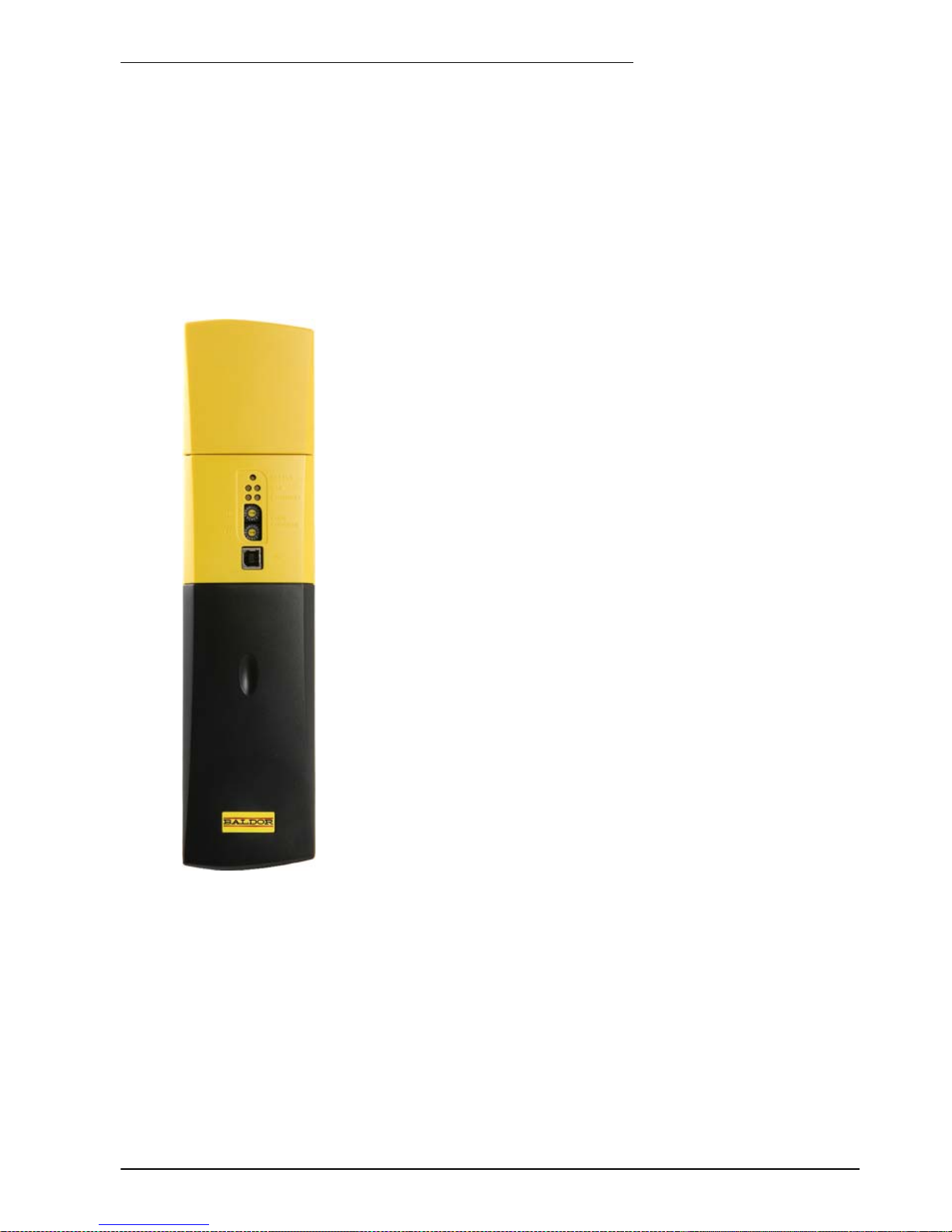
2.1 Mo t iFlex e100 features
The MotiFlex e100 is a versatile brushless servo drive, providing a flexible and powerful motion
control solution for rotary and linear motors. Standard features include:
H Single axis AC brushless drive.
H Range of models with continuous current ratings of:
1.5 A, 3 A, 6 A, 10.5 A, 16 A, 21 A, 26 A, 33.5 A, 48 A and 65 A.
H Direct connection to 230 - 480 VAC three-phase supplies.
H Ability to provide power to, or derive power from, a DC busbar
connection shared with neighboring drives.
H Universal feedback interface supporting incremental encoder, BiSS,
EnDat, SSI or SinCos feedback.
H Position, velocity and current control.
H Auto-tuning wizard (including position loop) and software oscilloscope
facilities provided by Mint WorkBench v5.5 configuration software
(supplied).
H 3 optically isolated general purpose digital inputs. Two inputs have
‘fast input’ capability, providing real-time position capture.
H 1 optically isolated drive enable input.
H 1 optically isolated general purpose digital output.
H 1 optically isolated digital output to indicate error conditions.
H 1 motor temperature switch input.
H 1 general purpose ±10 V analog input.
H USB 1.1 serial interface (compatible with USB 2.0).
H CANopen protocol for communication with Mint controllers and other
third party CANopen devices.
H Ethernet POWERLINK & TCP/IP support: Twin Ethernet ports with
integrated hub for communication with host PC or other Ethernet
POWERLINK devices.
H Programmable in Mint.
MotiFlex e100 can operate a large range of brushless rotary and linear servo motors. It can also
operate induction motors using closed-loop vector control. For information on selecting Baldor
motors, please see the sales brochure BR1202 available from your local Baldor representative.
This manual is intended to guide you through the installation of MotiFlex e100. The sections
should be read in sequence.
The Basic Installation section describes the mechanical installation of the MotiFlex e100, the
power supply connections and motor connections. The other sections require knowledge of the
low level input/output requirements of the installation and an understanding of computer software
installation. If you are not qualified in these areas you should seek assistance before proceeding.
2 Introduction
2
Page 14

www.baldormotion.com
2-2 Introduction MN1943
2.2 Receiving and inspection
When you receive your MotiFlex e100, there are several things you should do immediately:
1. Check the condition of the shipping container and report any damage immediately to the
carrier that delivered your MotiFlex e100.
2. Remove the MotiFlex e100 from the shipping container and remove all packing material. The
container and packing materials may be retained for future shipment.
3. Verify that the catalog number of the MotiFlex e100 you received is the same as the catalog
number listed on your purchase order. The catalog number is described in the next section.
4. Inspect the MotiFlex e100 for external damage during shipment and report any damage to
the carrier that delivered your MotiFlex e100.
5. If MotiFlex e100 is to be stored for several weeks before use, be sure that it is stored in a
location that conforms to the storage humidity and temperature specifications shown in
section 8.8.
Note: The 48 A and 65 A MotiFlex e100 have a recess at the rear of the product which is
filled with a block of packaging foam. Remove this foam before mounting the drive.
2.2.1 Identifying the catalog number
The MotiFlex e100 is available with different current ratings. The catalog number is marked on
the side of the unit. It is a good idea to look for the catalog number (sometimes shown as ID/No:)
and write it in the space provided here:
Catalog number:
MFE_____________________
Installed at: ________________________
Date: ______
A description of a catalog number is shown here, using the example MFE460A003x:
Meaning Alternatives
MFE MotiFlex e100 family -
460 Requires an AC supply voltage of 230 - 480 Volts, 3Φ -
A003 Continuous current rating of 3 A
A001=1.5 A; A006=6 A;
A010=10.5 A; A016=16 A;
A021=21 A; A026=26 A;
A033=33.5 A; A048=48 A;
A065=65 A
x A letter indicating the hardware revision. This does not
affect the capabilities of the MotiFlex e100 unless
otherwise stated.
-
Page 15

www.baldormotion.com
Introduction 2-3MN1943
2.3 Units and abbreviations
The following units and abbreviations may appear in this manual:
V Volt (also VAC and VDC)...............
WWatt..............
A Ampere...............
Ω Ohm...............
μF microfarad..............
pF picofarad..............
mH millihenry.............
Φ phase...............
ms millisecond..............
μs microsecond..............
ns nanosecond..............
mm millimeter.............
m meter...............
in inch...............
ft feet...............
lbf-in pound force inch (torque)............
N·m Newton meter (torque).............
ADC Analog to Digital Converter............
ASCII American Standard Code for Information Interchange...........
AWG American Wire Gauge............
CAL CAN Application Layer............
CAN Controller Area Network............
CDROM Compact Disc Read Only Memory.........
CiA CAN in Automation International Users and Manufacturers Group e.V..............
CTRL+E on the PC keyboard, press Ctrl then E at the same time..........
DAC Digital to Analog Converter............
DS301 CiA CANopen Application Layer and Communication Profile..........
DS401 CiA Device Profile for Generic I/O Devices..........
DS402 CiA Device Profile for Drives and Motion Control..........
DS403 CiA Device Profile for HMIs..........
EDS Electronic Data Sheet............
EMC Electromagnetic Compatibility............
EPL Ethernet POWERLINK............
HMI Human Machine Interface.............
ISO International Standards Organization.............
Kbit/s kilobits per second...........
LCD Liquid Crystal Display............
Mbit/s megabits per second...........
MB megabytes.............
MMC Mint Machine Center............
(NC) Not Connected............
RF Radio Frequency..............
SSI Synchronous Serial Interface.............
TCP/IP Transmission Control Protocol / Internet Protocol..........
UDP User Datagram Protocol............
Page 16

www.baldormotion.com
2-4 Introduction MN1943
2.4 Standards
The MotiFlex e100 has been designed and tested to comply with the following standards.
2.4.1 Design and test standards
H UL508C: Power Conversion Equipment.
H UL840: Insulation coordination including clearance and creepage distances for
electrical equipment.
H EN61800-5-1: Adjustable speed electrical power drive systems. Safety requirements.
Electrical, thermal and energy.
H EN50178: Electronic equipment for use in power installations.
H EN60529: Degrees of protection provided by enclosures.
H EN61800-3: When installed as directed in this manual, MotiFlex e100 conforms to the
category C3 emission limits and the ‘second environment’ immunity
requirements defined by this standard.
See also the CE certificate on page D-2.
2.4.2 Environmental test standards:
H EN60068-1: Environmental testing, general and guidance.
H EN60068-2-32: Environmental testing, Test Ed. Free Fall.
H EN60068-2-2: Environmental testing, Test B. Dry heat.
H EN60068-2-78: Environmental testing, Test cab. Damp heat, steady state.
2.4.3 Marks
See also Appendix D for general recommendations for CE compliance.
Page 17

www.baldormotion.com
Basic Installation 3-1MN1943
3.1 Introduction
You should read all the sections in Basic Installation to ensure safe installation.
This section describes the mechanical and electrical installation of the MotiFlex e100 in the
following stages:
H Location considerations.
H Mounting the MotiFlex e100.
H Connecting the AC power supply.
H Connecting the optional 24 VDC control circuit backup supply.
H Connecting the motor.
H Installing a regeneration resistor (Dynamic Brake).
3.1.1 Power sources
A 230 - 480 VAC 3-phase power source (IEC1010 over-voltage category III or less) in the
installation area is required. An AC power filter is required to comply with the CE directive for
which the MotiFlex e100 was tested (see section 3.4.10).
The optional 24 VDC control circuit backup supply must be a regulated power supply with a
continuous current supply capability of up to 1.5 A, dependent on the number of option cards
fitted. See section 3.6 for details.
3.1.2 Hardware requirements
The components you will need to complete the basic installation are:
H AC power supply filter (for CE compliance).
H The motor that will be connected to the MotiFlex e100.
H A motor power cable.
H An incremental encoder feedback cable, SSI cable, or BiSS / EnDat / SinCos cable.
A separate Hall cable might also be required for linear motors.
H A USB cable.
H (Optional) 24 VDC control circuit backup power supply.
H (Optional) A regeneration resistor (Dynamic Brake) might be required, depending on the
application. Without the regeneration resistor, the drive may produce an overvoltage fault. All
MotiFlex e100 models have overvoltage sensing circuitry. Regeneration resistors may be
purchased separately - see section 3.8 and appendix A.
3 Basic Installation
3
Page 18

www.baldormotion.com
3-2 Basic Installation MN1943
H A PC with the following minimum specification:
Minimum specification Recommended specification
Processor 32-bit Intel / AMD processor,
500 MHz
32-bit or 64-bit Intel / AMD dualcore processor, 2 GHz or faster
RAM 256 MB 1GB
Hard disk space 100 MB 100 MB
Communication USB port (USB 1.1 full-speed), or
Ethernet port (100 Mbit/s, independent of office network)*
Screen 1024 x 768, 16-bit color 1280 x 1024, 16-bit color
Mouse A mouse or similar pointing device.
(Mint WorkBench does not support touch)
Operating
system
Windows XP Windows XP, Windows Vista, or
Windows 7 (32-bit or 64-bit)
* The Ethernet configuration used by a normal office PC is not suitable for direct
communication with the MotiFlex e100. It is recommended to install a separate dedicated
Ethernet adapter in the PC, which can be configured for use with the MotiFlex e100. See
section 6.2.4.
3.1.3 Tools and miscellaneous hardware
H Your PC operating system user manual might be useful if you are not familiar with Windows.
H Small screwdriver(s) with a blade width of 2.5 mm (1/10 in) or less for connector X3.
H M5 screws or bolts for mounting the MotiFlex e100.
3.1.4 Other information needed for installation
This information is useful (but not essential) to complete the installation:
H The data sheet or manual provided with your motor, describing the wiring information of the
motor cables/connectors.
H Knowledge of whether the digital input signals will be ‘Active Low’ or ‘Active High’.
Page 19
www.baldormotion.com
Basic Installation 3-3MN1943
3.2 Mech an ical installation
It is essential that you read and understand this section before beginning the
installation
.
Take care when lifting. The 48 A and 65 A models weigh 12.45 kg (27.4 lb). Seek
assistance if necessary. When carrying, do not suspend the unit from the
removable front panels as they could detach and cause the unit to be dropped.
Avoid locating the MotiFlex e100 immediately above or beside heat generating
equipment, or directly below water steam pipes.
Avoid locating the MotiFlex e100 in the vicinity of corrosive substances or vapors,
metal particles and dust.
Failure to meet cooling air flow requirements will result in reduced product lifetime
and/or drive overtemperature trips.
The safe operation of this equipment depends upon its use in the appropriate environment.
The following points must be considered:
H The MotiFlex e100 must be installed indoors, permanently fixed and located so that it can
only be accessed by service personnel using tools. When installed in a cabinet, the cabinet
must have a volume of at least 0.19 m
3
(6.84 cu.ft). If not installed in a cabinet, barriers
around the equipment are required.
H The maximum suggested operating altitude is 1000 m (3300 ft).
H The MotiFlex e100 must be installed where the pollution degree according to EN61800-5-1
shall not exceed 2.
H The optional 24 VDC control circuit backup supply must be installed so that the 24 VDC
supplied to the unit is isolated from the AC supply either by using double or reinforced
insulation, or by using basic insulation with a protective earth.
H The input of the control circuit must be limited to Extra Low Voltage circuits.
H Both the AC supply and the optional 24 VDC control circuit backup supply must be fused.
H The atmosphere must not contain flammable gases or vapors.
H There must not be abnormal levels of nuclear radiation or X-rays.
H To comply with CE directive 2004/108/EC an appropriate AC filter must be installed.
H The MotiFlex e100 must be secured by the slots in the metal mounting flanges. The
protective earth/ground (the threaded studs on the top and bottom mounting flanges) must
be bonded to a safety earth/ground using either a 25 A conductor or a conductor of three
times the peak current rating - whichever is the greater.
H The metal tab at the bottom of the case is used for attaching a cable clamp (section A.1.6).
H The D-type connectors on the top and bottom panels of the MotiFlex e100 are secured using
two hexagonal jack screws (sometimes known as “screwlocks”). If a jack screw is removed
accidentally or lost it must be replaced with a #4-40 UNC jack screw with an external male
threaded section no longer than 10 mm (0.4 in).
H The 48 A and 65 A MotiFlex e100 have a recess at the rear of the product which is filled
with a block of packaging foam. Remove this foam before mounting the drive.
CAUTION
NOTICE
NOTICE
NOTICE
Page 20
www.baldormotion.com
3-4 Basic Installation MN1943
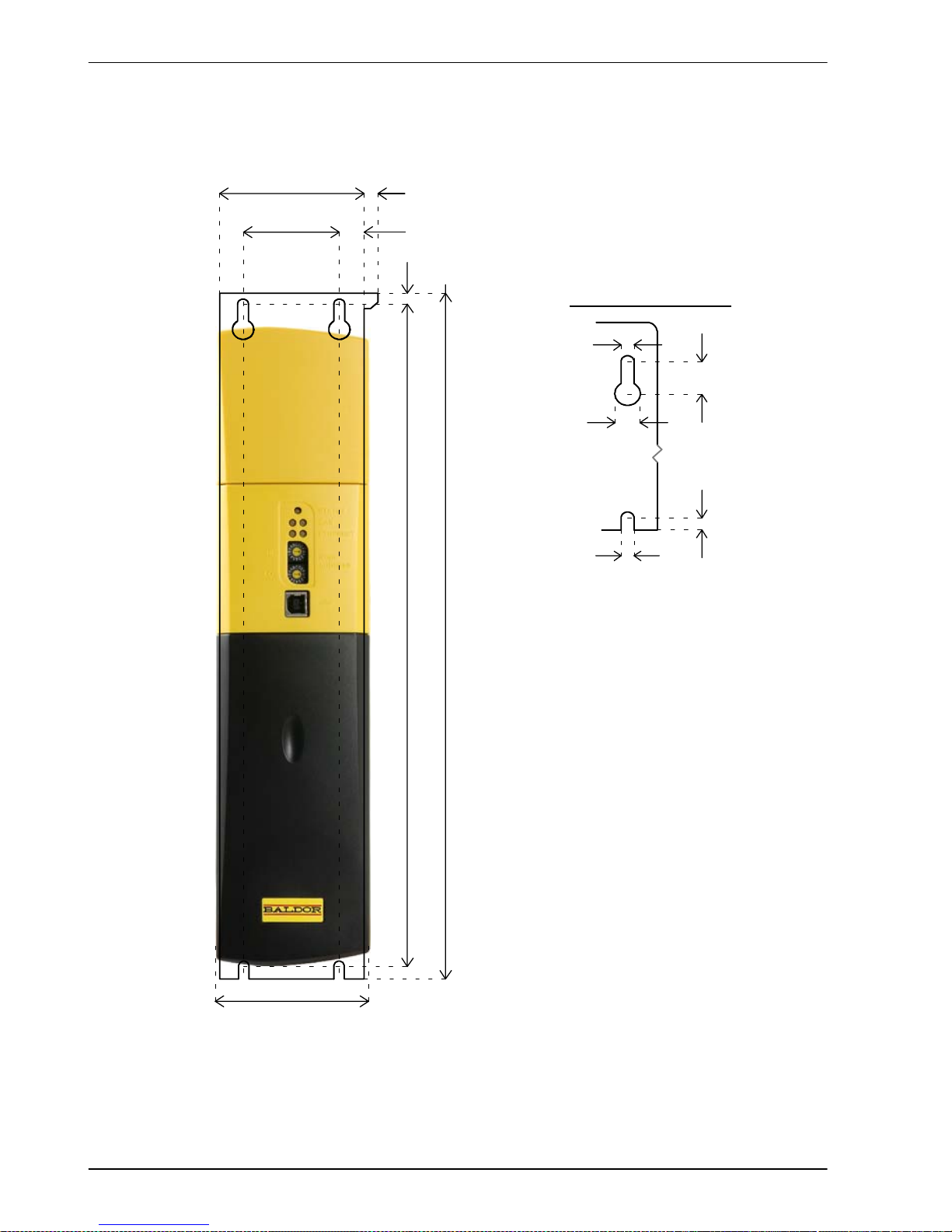
3.2.1 Dimensions - 1.5 A ~ 16 A models
75
(2.95)
50
(1.97)
350
(13.78)
362
(14.25)
6
(0.24)
12.5
(0.49)
Mounting hole and s lot detail
Dimensions shown as: mm (inches ).
Depth: 260 mm (10.24 in)
Weight: 1.5 A: 1.90 kg (4.2 lb)
3A: 1.90kg(4.2 lb)
6A: 1.90kg(4.2 lb)
10.5A: 4.80kg(10.6 lb)
16 A: 5.80 kg (12.8 lb)
8
(0.31)
A
B
C
A 6mm
B 12 mm
C 12.7 mm
D 6mm
E 6mm
D
E
Note: The case is 76 mm wide, which
is 1 mm wider thanthe mountingplate.
For this reason, when mounting
multiple drives side-by-side for DC
bus s haring, it is adv isable to use the
method described in section 3.2.4.1 to
avoid errors when marking hole
positions.
76
(2.99)
Figure 1 - Mounting and overall dimensions - 1.5 A ~ 16 A models
Page 21

www.baldormotion.com
Basic Installation 3-5MN1943
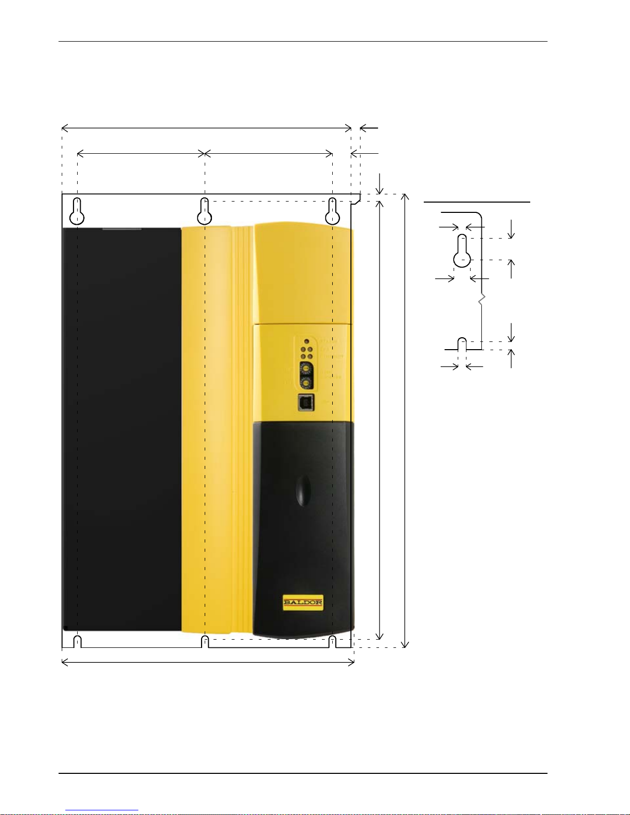
3.2.2 Dimensions - 21 A ~ 33.5 A models
127
(4.99)
100
(3.94)
350
(13.78)
362
(14.25)
6
(0.24)
13.5
(0.53)
Mounting hole and s lot detail
Dimensions shown as: mm (inches ).
Depth: 260 mm (10.24 in)
Weight: 21 A: 5.85 kg (12.9 lb)
26 A: 6.35 kg (14.0 lb)
33.5 A: 6.35 kg (14.0 lb)
8
(0.31)
A
B
C
A 6mm
B 12 mm
C 12.7 mm
D 6mm
E 6mm
D
E
Note: The case is 128 mm wide, which
is 1 mm wider than the mounting plate.
For this reason, when mounting
multiple drives side-by-side for DC
bus s haring, it is adv isable to use the
method described in section 3.2.4.1 to
avoid errors when marking hole
positions.
128
(5.04)
Figure 2 - Mounting and overall dimensions - 21 A ~ 33.5 A models
Page 22
www.baldormotion.com
3-6 Basic Installation MN1943
3.2.3 Dimensions - 48 A ~ 65 A models
212
(8.35)
92.5
(3.64)
350
(13.78)
362
(14.25)
6
(0.24)
13.5
(0.53)
Mounting hole and s lot detail
Dimensions shown as: mm (inches
)
Depth: 260 mm (10.24 in)
Weight: 48 A: 12.45 kg (27.4 lb)
65 A: 12.45 kg (27.4 lb)
8
(0.31)
A
B
C
A 6mm
B 12 mm
C 12.7 mm
D 6mm
E 6mm
D
E
Note: The c ase is 213 mm wide,
which is 1 mm wider than the
mounting plate. For this reason,
when mounting multiple drives
side-by-side for DC bus sharing, i t
is advisable to use the method
described in section 3.2.4.1 to
avoid errors when marking hole
positions.
213
(8.39)
92.5
(3.64)
Figure 3 - Mounting and overall dimensions - 48 A ~ 65 A models
Page 23
www.baldormotion.com
Basic Installation 3-7MN1943
3.2.4 Mounting the MotiFlex e100
Ensure you have read and understood the Mechanical installation and location requirements in
section 3.2. Mount the MotiFlex e100 vertically on its rear side, the side opposite the front panel.
M5 bolts or screws should be used to mount the MotiFlex e100. Detailed dimensions are shown
in section 3.2.1.
Note: The 48 A and 65 A MotiFlex e100 have a recess at the rear of the product which is
filled with a block of packaging foam. Remove this foam before mounting the drive.
For effective cooling, the MotiFlex e100 must be mounted upright on a smooth vertical metal
surface. The MotiFlex e100 is designed to operate in an ambient temperature of 0 °C to 45 °C
(32 °F to 1 13 °F). Output current must be derated between 45 °C (1 13 °F) and the absolute
maximum ambient temperature of 55 °C (131 °F). All models incorporate cooling fans and are
designed to operate without any additional cooling methods.
Temperature derating characteristics are shown in sections 8.3.5 to 8.3.14.
3.2.4.1 Mounting multiple drives for DC bus sharing
The MotiFlex e100 is designed to be mounted in close contact with other MotiFlex e100s, to allow
the optional DC busbar kits (Baldor parts OPT-MF-DC-A, -B, -C or -D) to be connected across
the top of the drives. Each busbar kit contains two busbars and the necessary screws. When
mounting drives for DC bus sharing it is essential that they are accurately positioned in contact
with the neighboring drive, otherwise the busbars will not fit.
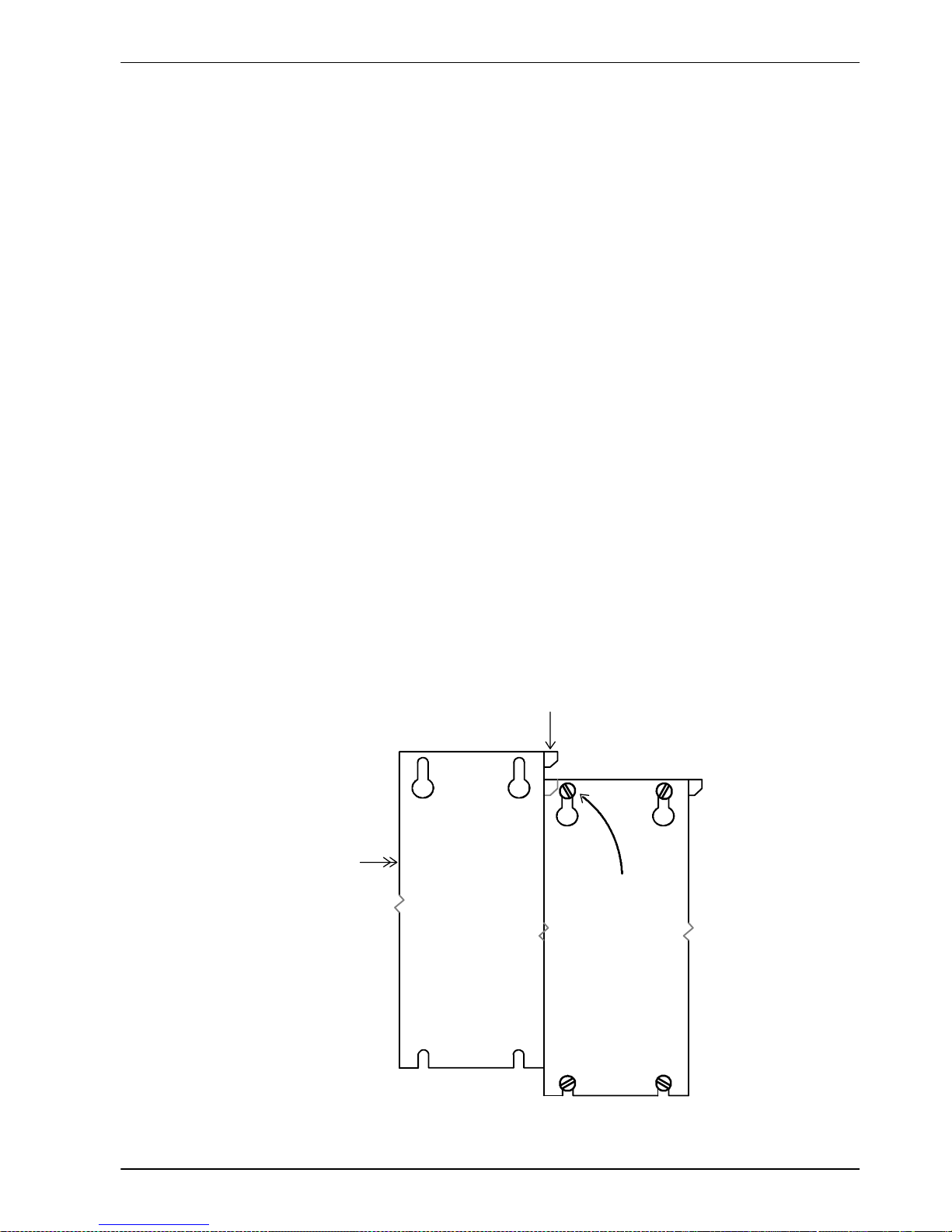
Mount the rightmost drive first, but do not fully tighten the top left screw. Take the next drive and
hold it against the left side of the first drive. Slide it downwards until the alignment tab (see Figure
4) on the side of the mounting flange fits behind the matching cutout on the first drive’s mounting
flange. Tighten the first drive’s top left screw. Holding the second drive in place, mark its mounting
holes. Remove the second drive, finish the mounting holes and then remount the drive. Use the
same procedure to mount further drives to the left of the second drive.
Alignment tab
1. Mount rightmost
drive first, leaving
top left screw
slightly loose.
2. Press second drive
against the first drive...
3. ...and slide down until alignment
tab engages behind fi rst drive.
FRONT
FRONT
Figure 4 - Mounting MotiFlex e100s for DC bus sharing
Page 24
www.baldormotion.com
3-8 Basic Installation MN1943
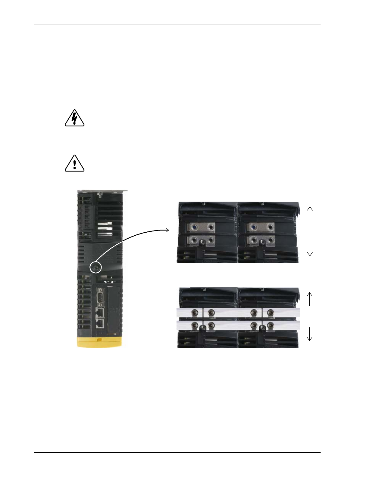
3.2.4.2 Attaching the busbars for DC bus sharing
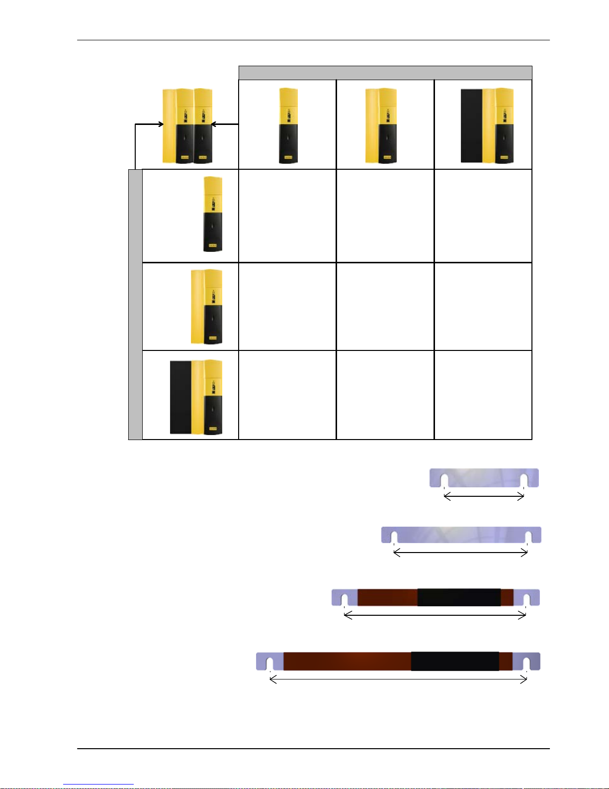
Busbars are supplied in kits, comprising a pair of busbars and all screws and washers required
for fitting. There are 4 different busbar sizes, allowing any combination of narrow bodied
MotiFlex e100 (1.5 A ~ 16 A models), wide bodied MotiFlex e100 (21 A ~ 33.5 A models) or
extended bodied MotiFlex e100 (48 A ~ 65 A models) to be connected, as shown in Figure 6. Size
3 and size 4 busbars have an insulating sleeve, since parts of them are exposed when fitted. See
also section 3.5 for details about sharing the DC bus.
Hazardous voltages exist underneath the drive’s hinged top cover! Before
lifting the cover ensure that AC power has been removed from the source
drive and at least 5 minutes have elapsed to allow the DC bus output
capacitors to discharge. Use only original Baldor busbar kits, parts
OPT-MF-DC-x.
Always observe the correct polarity. The busbar nearest the front of the
MotiFlex e100 is positive. The busbar at the rear is negative, as shown in Figure 5.
1. Loosen the busbar c over retaining screw to reveal the busbar
mounting pads.
2. Attach the busbars using the supplied screws and washers.
Tighten screws to approximately 2 N·m (17.7 lb-in).
3. Close the busbar cover and tighten the retaining screw to
approximately 1 N·m (8.9 lb-in). Do not exceed 2 N·m (17.7 lb-in).
+
-
+
-
+
+
-
+
-
Front
Rear
Front
Rear
Figure 5 - Connecting busbars for DC bus sharing
DANGER
WARNING
Page 25
www.baldormotion.com
Basic Installation 3-9MN1943
55 mm
Size 1 busbar - kit OPT-MF-DC-A
Size 2 busbar - kit OPT-MF-DC-B
107 mm
Size 3 busbar - kit OPT-MF-DC-C
140.4 mm
Size 4 busbar - kit OPT-MF-DC-D
192 mm
A
B
C
D
B
B
BD
A
1.5 - 16 A
21 - 33.5 A
48 - 65 A
1.5 - 16 A
21 - 33.5 A
48 - 65 A
RIGHT
Busbar selection:
1) From the LEFT column, select the
drive that will be on the left.
2) From the RIGHT row, select the drive
that will be on the right.
3) The intersecting letter indicates the
busbar required to connect the
selected drives.
For example, B indicates that
OPT-MF-DC-B is required.
LEFT
Figure 6 - Busbar requirements according to drive combinations
Page 26

www.baldormotion.com
3-10 Basic Installation MN1943
3.2.5 Overtemperature trips and intelligent fan control
The MotiFlex e100 contains internal temperature sensors that will cause it to trip and disable if
the control card or output power module temperatures exceed preset values. These values are
listed in the following table, and can also be read using the TEMPERATURELIMITFATAL
keyword - see the Mint help file for details.
MotiFlex e100
catalog number
Maximum control card
temperature
Maximum power module (PIM)
temperature
MFE460A001
MFE460A003
105 °C
(
221 °F
)
MFE460A006
73 °C
(
163.4 °F
)
(221F
)
MFE460A010
(16
3.4F)
115 ° C
MFE460A016
115
C
(239 °F)
MFE460A021
MFE460A026
62 °C
(
143.6 °F
)
115 ° C
(
239 °F
)
MFE460A033
(14
3.6F)(239F)
MFE460A048
62 °C 115 ° C
MFE460A065
62C
(143.6 °F)
115
C
(239 °F)
Ta ble 1 - Maximum internal trip temperatures
The MotiFlex e100 can detect problems with its cooling fan, such as disconnection (fan loss) or
overcurrent caused by stalling. The 10.5 A and 16 A models incorporate two cooling fans; one
fan operates continuously, but to increase overall lifetime and efficiency the second fan operates
only when necessary. Also, if a fault is detected on the first fan, the other one will turn on. The
48 A and 65 A models incorporate four cooling fans; none of the fans are required in normal
conditions, but all four will operate when necessary.
3.2.5.1 Effects of mounting surface and proximity
If the MotiFlex e100 is mounted above or below another MotiFlex e100 (or other obstruction),
there should be a minimum space of 90 mm to maintain effective cooling. Remember that when
a MotiFlex e100 is mounted above another MotiFlex e100 or heat source, it will be receiving air
that has been already heated by the device(s) below it.
Page 27
www.baldormotion.com
Basic Installation 3-11MN1943
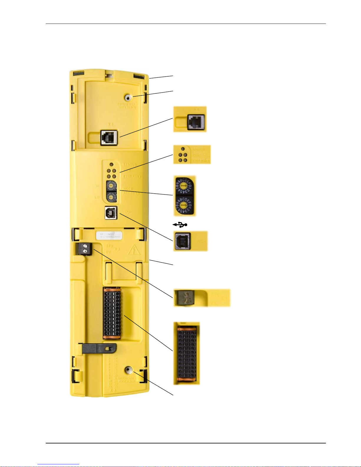
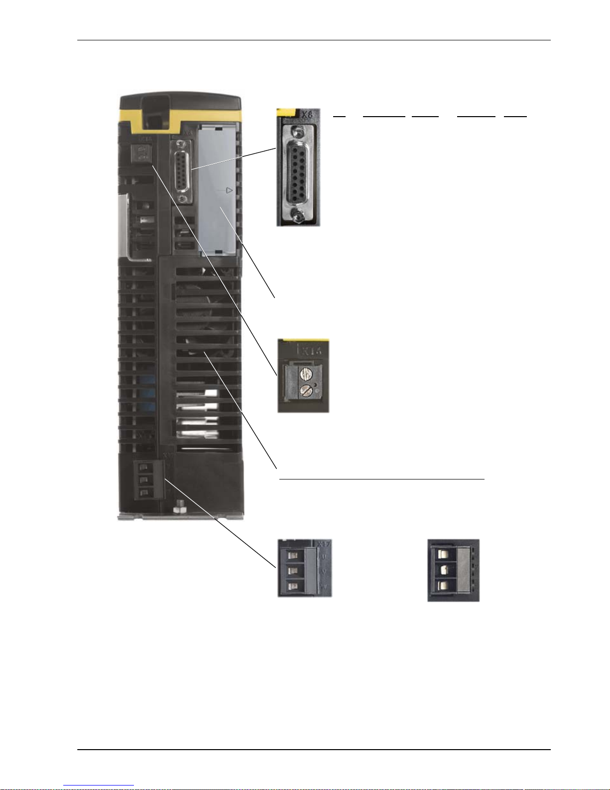
3.3 Connecto r locatio n s
3.3.1 Front panel connectors
13 Status+
14 DGND
15 DOUT1+
16 DIN2+
17 DGND
18 DIN1+
19 DIN0+
20 DGND
21 Drive enable+
22 Shield
23 A GND
24 A IN0+
1 (NC)
2 Data3 Data+
4GND
X3 Input / Output
USB
1 Status2DGND
3DOUT14DIN25DGND
6DIN17DIN08DGND
9 Driv e enable10 Shield
11 AGN D
12 AIN0-
Node ID
These switches set the MotiFlex e100’s
node ID for Ethernet POWERLINK, and the
final value of the IP address when using
TCP/IP. See sections 5.8.1 and 6.2.4.
LEDs
The STATUS, CAN and ETHERNET
LEDs are described i n section 7.2.1.
Tightening torque for terminal block connections (X2 & X3) is 0.5-0.6 N·m (4.4-5.3 lb-in).
Tightening torque for option slot 1/2 retaining screws is 0.7 N·m (6.2 lb-in).
Maximum wire / ferrule size (X2): 2.5 mm2(14 AWG).
Maximumwiresize(X3):0.5mm2(20 AWG). Connector X 3 is designed to accept bare wires only; do not use
bootlace ferrules.
(NC) = Not Connected. Do not mak e a c onnection to this pin.
18 V out / 24 V in
0V
X2 18 VDC output / 24 VDC backup input
Option slot 1 retaining screw.
Option slot 2 retaining screw.
Toremovethetop cover,pushonthe center of the bottom edge, then pull
thetopedge forwards.To refit,locate thecover overits intended position
and then push on until it snaps into place.
To remove the bottom cover, push on the oval indentation and slide the
cover downwards.To refit, insert thetwotabs, protrudingfromthe cover’s
topedge,intothemainbody. Push ontheBaldorlabel tosnap intoplace.
1TXA
2TXB
3GND
4 +7V out
5 (NC)
6 (NC)
X6 RS485 (2-wire)
Page 28

www.baldormotion.com
3-12 Basic Installation MN1943
3.3.2 Top panel connectors
CAN
1 (NC)
2CAN3CANGND
4 (NC)
5 S hield
6CANGND
7CAN+
8 (NC)
9 CAN V+
Ethernet
1TX+
2TX3RX+
4 (NC)
5 (NC)
6RX-
7 (NC)
8 S hield
Both connectors have
identical pinouts.
X1 AC power & regen
(1.5A~16Amodels)
L1 AC Phase 1
L2 AC Phase 2
L3 AC Phase 3
R1
R2
Option slot 1 cover
Busbar cover retaining screw. Tightening torque i s 1 N·m (8.9 lb-in).
Tightening torque:
0.5-0.6 N·m (4.4-5.3 lb-in)
Maximum wire / ferrule size:
X1: 4 mm2(11 AWG).
Regeneration
resistor
X1 AC power & regen
(21A~65Amodels)
Tightening torque:
L1/L2/L3: 1.7 N·m (15 l b-in)
R1/R2: 1.7 N·m (15 l b-in)
Maximum wire / ferrule size:
L1/L2/L3: 16 mm2(5 AWG).
R1/R2: 16 mm2(5 AWG).
L1 AC Phase 1
L2 AC Phase 2
L3 AC Phase 3
Regeneration
resistor
R1
R2
Page 29
www.baldormotion.com
Basic Installation 3-13MN1943
3.3.3 Bottom panel connectors
X8 Feedback In
Pin Inc remental SinCos BiSS / SSI EnDat
1 CHA+ (NC) Data+ Data+
2 CHB+ (NC) Clock+ Clock+
3 CHZ+ (NC) (NC) (NC)
4 Sense Sense Sense Sense
5HallU-Sin- (NC) Sin-*
6HallU+Sin+ (NC) Sin+*
7 Hall V- Cos- (NC) Cos-*
8 Hall V+ Cos+ (NC) Cos+*
9 CHA- (NC) Data- Data10 CHB- (NC) Clock- Clock11 CHZ- (NC) (NC) (NC)
12 +5V out +5V out +5V out +5V out
13 DGND DGND DGND DGND
14 Hall W- (NC) (NC) (NC)
15 Hall W+ (NC) (NC) (NC)
Shell Shield Shield Shield Shield
* EnDat v2.1 only. EnDat v2.2 does not use the Sin and
Cos signals.
X16 Motor temperature switch
X17 Motor power out
(1.5A~16Amodels)
U Motor U out
V Motor V out
W Motor W out
1TH1
2TH2
Option slot 2 cover
Tightening torque:
0.5-0.6 N·m (4.4-5.3 lb-in).
Maximum wi re size:
4mm2(11 AWG).
Cooling fan air inl et slots.
Ensure these slots remain free of obstructions at all times.
X17 Motor power out
(21A~65Amodels)
Tightening torque: 0.5-0.6 N·m (4.4-5.3 lb-in).
Maximum wire size: 2.5 mm2(14 AWG).
Tightening torque:
1.7 N·m (15 lb-in).
Maximum wi re size:
16 mm2(5 AWG).
U Motor U out
V Motor V out
W Motor W out
IMPORTANT NOTE!
Motor power cables must be correctly bonded to earth.
See section 3.7.1 for details.
Page 30
www.baldormotion.com
3-14 Basic Installation MN1943
3.4 AC power connections
This section provides instructions for connecting the AC power supply. For full specifications,
see section 8.
The installer of this equipment is responsible for complying with NEC (National Electric Code)
guidelines or CE (Conformite Europeene) directives and application codes that govern wiring
protection, earthing/grounding, disconnects and other current protection.
Electrical shock can cause serious or fatal injury. Do not touch any power
device or electrical connection before you first ensure that power has been
disconnected and there is no high voltage present from this equipment or
other equipment to which it is connected.
To prevent equipment damage, be certain that the input power has correctly rated
protective devices installed.
To prevent equipment damage, be certain that input and output signals are powered
and referenced correctly.
To ensure reliable performance of this equipment be certain that all signals to/from
the MotiFlex e100 are shielded correctly.
MotiFlex e100 drives are designed to be powered from standard three-phase lines that are
electrically symmetrical with respect to earth/ground. The power supply module within all
MotiFlex e100 models provides rectification, smoothing and current surge protection. Fuses or
circuit breakers are required in the input lines for cable protection.
Note: A Residual Current Device (RCD) must not be used for fusing the drive.
An appropriate type of circuit breaker or fuse must be used.
All interconnection wires should be in metal conduits between the MotiFlex e100, AC power
source, motor, host controller and any operator interface stations.
3.4.1 Earthing / grounding
Permanent earth/ground bonding points are provided on the mounting flanges, which must be
used as the protective earth. They are labeled with the protective earth symbol and do not form
any other mechanical function. Earthing methods are shown in section 3.4.4.
These protective earth/ground points prevent exposed metal parts of the MicroFlex e100 from
becoming live in the event of a wiring error or other failure. Connecting these points to earth does
not provide protection against electromagnetic contamination received or emitted by the drive
and its associated wiring. For example, the motor power output cable supplies a high frequency
high current waveform to the motor, so the cable’s shielding must be separately bonded to a
functional earth point to prevent the cable radiating electromagnetic contamination into the
surrounding area. Such contamination can cause spurious errors in apparently unrelated parts
of the installation, such as low voltage communication cables. See sections 3.4.2 and 3.7.1 for
detailed installation instructions that will help reduce electromagnetic contamination.
Note: When using unearthed/ungrounded distribution systems, an isolation transformer
with an earthed/grounded secondary is recommended. This provides three-phase
AC power that is symmetrical with respect to earth/ground and can prevent
equipment damage.
DANGER
NOTICE
NOTICE
NOTICE
Page 31

www.baldormotion.com
Basic Installation 3-15MN1943
3.4.2 AC input and regeneration resistor output wiring
The installation methods shown in Figure 7 will improve the reliability of the system, reduce
troubleshooting time, and optimize the EMC (electromagnetic compatibility) behavior of the
control system. The MotiFlex e100’s protective earth connection does not provide
electromagnetic compatibility. Its purpose is to prevent exposed metalwork becoming live in the
case of a serious failure. T o avoid EMC coupled effects within the panel design:
1. Do not run AC filter input and output power cables in close proximity.
2. Do not run motor output power cables with any other cables, especially Ethernet, signal
cables, or ’clean’ AC power.
3. Do not run power and signal cables in the same trunking. If the cables must run in parallel,
they should be separated by 200 mm (8 in) or placed in separate metal trunking.
4. If any of the above cables must cross, they must do so at 90 degrees to minimize coupling.
5. Ensure all sources of electrical noise are suppressed, e.g. solenoids, relays, contactors.
AC power
from fuses
and reactor
Mount AC filter and
MotiFlex e100 on the
same metal panel.
Regeneration resistor.
For long cables, use
shielding as shown for AC
power cables.
DO NOT TOUCH!
Regeneration resistors can
become extremely hot!
Locate away from vulnerable
components and wiring
Connect AC power cable shield to
metal panel, using conductive shield
earth/ground clamps.
Drive
earth
must be
at least
10 mm
2
(7 AWG)
OPT-CM-001
AC power wires
should be as short as
possible, typically
less than 0.3 m (1 ft).
Longer wires must
be shielded as
shown.
Wire colors
may vary
according
to region.
CAUTION
Figure 7 - Panel layout best practice
Page 32

www.baldormotion.com
3-16 Basic Installation MN1943
3.4.3 Earth leakage
The following table shows typical earth leakage figures for a MotiFlex e100 with a 20 m (66 ft)
motor cable, in combination with each of the recommended AC power filters (see section 3.4.10).
MotiFlex e100 with:
Typical combined earth leakage
AC power filter Motor cable
Typicalcombinedearthleakage
(mA)
None None 6.24
FI0035A00 (8 A) 20 m 28.6
FI0035A01 (16 A) 20 m 38.7
FI0035A02 (25 A) 20 m 38.7
FI0035A04 (50 A) 20 m 45.4
FI0035A05 (66 A) 20 m 60.0
If the MotiFlex e100 and filter are mounted in a cabinet, the minimum size of the protective
earthing conductor shall comply with the local safety regulations for high protective earthing
conductor current equipment. The conductor must be 10 mm
2
or larger to satisfy EN61800-5-1.
3.4.3.1 Protection class
User protection has been achieved using Protective Class I, which requires an earth connection
to the unit whenever hazardous voltages are applied. The equipment provides protection against
electric shock by:
H Means of connection of protective earth to accessible live conductive parts.
H Basic insulation.
Page 33

www.baldormotion.com
Basic Installation 3-17MN1943
3.4.4 AC power connections
Location Connector X1 (top panel)
Mating connector
1.5 A ~ 16 A models
21 A ~ 33 A models
48 A ~ 65 A models
Phoenix POWER COMBICON PC 4/ 5-ST-7,62
Phoenix POWER COMBICON PC 16/ 3-ST-10,16
Phoenix POWER COMBICON SPC 16/ 3-ST-10,16
Nominal input voltage 230 VAC or 480 VAC, 3Φ line to line
Minimum input voltage 180 VAC, 3Φ linetoline(seeNote)
Maximum input voltage 528 VAC, 3Φ line to line
Note: The MotiFlex e100 will trip if the DC-bus voltage falls below 200 V or 60% of the
no-load voltage, whichever occurs first. The MotiFlex e100 will stop operating if the
DC-bus voltage falls below 150 VDC, unless a 24 VDC control circuit backup supply
is present (see section 3.6).
Connect the supply to L1, L2 and L3 as shown in Figure 8. For CE compliance, an AC filter must
be connected between the AC power supply and the MotiFlex e100. If local codes do not specify
different regulations, use at least the same gauge wire for earth/ground as is used for L1, L2 and
L3. The threaded studs protruding from the top and bottom case flanges can be used as the
earth/ground connection (PE).
For 1.5 A ~ 16 A models, tightening torque for X1 terminal block connections is 0.5-0.6 N·m
(4.4-5.3 lb-in). The 21 A ~ 65 A models use a spring cage connector. For all models, tightening
torque for the flange mounted PE connection is 2.5 N·m (22.1 lb-in).
AC power wires should be as
short as possible, typically less
than 0.3 m (1 ft). Longer cables
must use shielded cable with
the outer shield bonded to the
unpainted backplane using a
metal P-clip.
AC
Supply
Line (L1)
Route L1, L2, L3 and
earth/ground together
in conduit or cable
Circuit breaker
or fuses. See
section 3.4.11
AC filter.*
See section
3.4.10
Line (L2)
Line (L3)
STAR POINT
Incoming safety
earth/ground (PE)
Isolating switch
Connect earth/ground
to protectiv e earth on
drive flange.
Optional AC line
reactor. See
section 3.4.9
* Mount filter and MotiFlex e100
on the same metal backplane.
Figure 8 - Three-phase power connections - 1.5 A ~ 16 A models
Page 34

www.baldormotion.com
3-18 Basic Installation MN1943
AC
Supply
Line (L1)
Route L1, L2, L3 and
earth/ground together
in conduit or cable
Circuit breaker
or fuses. See
section 3.4.11
AC filter.*
See section
3.4.10
Line (L2)
Line (L3)
STAR POINT
Incoming safety
earth/ground (PE)
Isolating switch
Connect earth/ground
to protectiv e earth on
drive flange.
Optional AC line
reactor. See
section 3.4.9
AC power wires should be as
short as possible, typically less
than 0.3 m (1 ft). Longer cables
must use shielded cable with
the outer shield bonded to the
unpainted backplane using a
metal P-clip.
* Mount filter and MotiFlex e100
on the same metal backplane.
Figure 9 - Three-phase power connections - 21 A ~ 65 A models
3.4.5 AC power cycling
After AC power has been removed, no delay is necessary before reapplying AC power. However,
note that after AC power has been removed from the MotiFlex e100, high voltages (greater than
50 VDC) can remain on power connections for up to 5 minutes, while the DC bus circuitry
discharges. Do not touch the DC bus, regeneration resistor, or other power connections during
this period.
3.4.6 Inrush current
The inrush current is limited by pre-charge circuitry and is lower than the maximum AC current
expected under full load conditions (see section 8), so it should not affect fusing or supply circuit
design.
3.4.7 Phase loss detection
The MotiFlex e100 requires all three phases to be present. If any phase is lost, the MotiFlex e100
will immediately trip and disable, reporting a phase loss error (error 10029). See the Mint help file
for details about handling errors.
3.4.8 Drive overload protection
The MotiFlex e100 will immediately trip and disable if there is an overload condition. The
parameters for managing drive overloads are configured automatically by the Commissioning
Wizard (see section 6.4.3). If they need to be changed, use the Parameters tool in Mint
WorkBench (see section 6.5.1).
Page 35

www.baldormotion.com
Basic Installation 3-19MN1943
3.4.9 Input power conditioning
Certain power line conditions must be avoided; an AC line reactor, an isolation transformer or a
step up/step down transformer may be required for some power conditions.
If the feeder or branch circuit that provides power to the MotiFlex e100 has permanently connected
power factor correction capacitors, an input AC line reactor or an isolation transformer must be
connected between the power factor correction capacitors and the MotiFlex e100.
AC line reactors may also be required under certain conditions, for example:
H If the AC supply harmonic distortion is greater than 5%. Harmonic distortion typically
occurs in regions where the quality of the AC supply is poor, for example Israel or India,
and in heavy industry.
H The supply phases are imbalanced. An imbalanced supply typically occurs where one
phase of the local three-phase supply is being used more than the other phases.
H The supply contains commutation notches. These typically occur in heavy industry, and
are caused by the commutation of large power semiconductor devices in equipment such
as large thyristor converters.
H The MotiFlex e100 is sharing its DC bus with other drives (see section 3.5).
See section A.1.3 for a range of suitable line reactors.
If the feeder or branch circuit that provides power to the MotiFlex e100 has power factor correction
capacitors that are switched on line and offline, the capacitors must not be switched while the drive
is connected to the AC power line. If the capacitors are switched on line while the drive is still
connected to the AC power line, additional protection is required. A Transient Voltage Surge
Suppressor (TVSS) of the proper rating must be installed between the AC line reactor (or isolation
transformer) and the AC input to the MotiFlex e100.
Page 36

www.baldormotion.com
3-20 Basic Installation MN1943
3.4.10 Power supply filters
To comply with EC directive 2004/108/EC, an AC power filter of the appropriate type must be
connected. This can be supplied by Baldor and will ensure that the MotiFlex e100 complies with
the CE specifications for which it has been tested. Ideally one filter should be provided for each
MotiFlex e100, except in DC bus sharing applications where only the source drive requires a
filter. Filters should not be shared between drives or other equipment. T able 2 lists the appropriate
filters:
MotiFlex e100
catalog
number
Recommended
Baldor AC
power filters
Filter
current
rating
(RMS)
Meets
EN61000-6-4
Industrial standard
(class A)
Meets
EN61800-3
Drives Standard
FI0035A00 8A No Yes
MFE460A00
1
FI0035A01 16A No Yes
FI0035A00 8A No Yes
MFE460A00
3
FI0035A01 16A No Yes
MFE460A006 FI0035A01 16A No Yes
FI0035A01 16A No Yes
MFE460A01
0
FI0035A02 25A Yes Yes
MFE460A016 FI0035A02 25A Yes Yes
FI0035A03 36A Yes Yes
MFE460A021
FI0035A04 50A No Yes
FI0035A05 66A No Yes
FI0035A03 36A Yes Yes
MFE460A026
FI0035A04 50A No Yes
FI0035A05 66A No Yes
FI0035A04 50A No Yes
MFE460A03
3
FI0035A05 66A No Yes
MFE460A048 FI0035A05 66A Yes Yes
MFE460A065 FI0035A05 66A Yes Yes
Ta ble 2 - Baldor filter part numbers
For filter earth leakage figures, see section 3.4.3.
Note: The MotiFlex e100 is not intended to be used on a low-voltage public network
which supplies domestic premises. Radio frequency interference is expected if
used on such a network.
Page 37

www.baldormotion.com
Basic Installation 3-21MN1943
3.4.11 Power disconnect and protection devices
A power disconnect should be installed between the input power supply and the MotiFlex e100
for a fail-safe method to disconnect power. The MotiFlex e100 will remain in a powered condition
until all input power is removed from the drive and the internal bus voltage has depleted. The
MotiFlex e100 must have a suitable input power protection device installed, preferably a fuse.
Recommended circuit breakers are thermal magnetic devices with characteristics suitable for
heavy inductive loads (C-type trip characteristic for 1.5 A ~ 16 A models, B-type trip
characteristic for 21 A ~ 65 A models. Circuit breaker or fuses are not supplied. See sections
8.2.2 to 8.2.4 for recommended ratings. For CE compliance, see Appendix D.
Circuit Breaker
Circuit breaker or fuse are not supplied.
For CE Compl iance, s ee Appendix C.
L1
From
supply
Fuses
L2
L3
L1
L2
L3
From
supply
L1
L2
L3
Figure 10 - Circuit breaker and fuses
Note: Metal conduit or shielded cable should be used. Connect conduits so the use of a
line reactor or RC device does not interrupt EMI/RFI shielding.
3.4.11.1Discharge period
After AC power has been removed from the MotiFlex e100, high voltages
(greater than 50 VDC) can remain on power connections for up to 5 minutes,
while the DC bus circuitry discharges. Do not touch the DC bus,
regeneration resistor, or other power connections during this period.
DANGER
Page 38

www.baldormotion.com
3-22 Basic Installation MN1943
3.4.12 Recommended wire sizes
All wire sizes are based on 75 °C (167 °F) copper wire. Use copper conductors only. Higher
temperature smaller gauge wire may be used per National Electric Code (NEC) and local codes.
MotiFlex e100
AC input & motor output wire size
catalog numbe
r
AWG mm
2
MFE..A001 14 2.5
MFE..A003 14 2.5
MFE..A006 14 2.5
MFE..A010 10 6.0
MFE..A016 10 6.0
MFE..A021 8 10.0
MFE..A026 8 10.0
MFE..A033 8 10.0
MFE..A048 4 20.0
MFE..A065 4 20.0
Ta ble 3 - AC input and motor output wire sizes
Page 39

www.baldormotion.com
Basic Installation 3-23MN1943
3.5 Sharing the DC bus
The AC power supply is rectified and smoothed within the MotiFlex e100 to create a typical ‘DC
bus’ voltage of around 678 VDC (when using a 480 VAC supply). The DC bus voltage is then
switched by a power module to create the UVW output waveforms that drive the motor. The
MotiFlex e100 is capable of sharing its DC bus voltage with similar drives mounted beside it, using
solid metal busbar connections between the drives. In a group of drives, this significantly reduces
the amount of AC power supply wiring, filters, fuses and breakers, since these are only required
by the single drive that is generating the DC bus voltage (the source drive). Furthermore, only one
regeneration resistor is required for the group (see section 3.8). The DC bus outputs are
conditionally short-circuit proof according to EN61800-5-1, 6.2. When sharing the DC bus, revised
AC input current ratings apply. See section 8.
3.5.1 DC busbar connection
Hazardous voltages exist underneath the drive’s hinged top cover! Before
lifting the cover ensure that AC power has been removed from the source
drive and at least 5 minutes have elapsed to allow the DC bus output
capacitors to discharge.
Always observe the correct polarity. The busbar nearest the front of the
MotiFlex e100 is positive. The busbar at the rear is negative, as shown in Figure 5.
When sharing the DC bus, special care must be taken to calculate the total peak and
continuous supply current requirement of the drives, since they will all derive power
from the source drive’s DC bus.
Only the source drive must be connected to the AC power source so that it can
generate the DC bus voltage. The receiving drives sharing the DC bus must not be
connected to the AC power source.
In the unlikely event that one of the MotiFlex e100’s DC bus capacitors should fail
with a short circuit, an internal fast-acting fuse will trip. These fuses are not user
replaceable. Similar fuses in other drives sharing the DC bus are also likely to trip.
The top panel of the MotiFlex e100
incorporates a cover that conceals the DC
busbar output pads. To allow sharing of the
DC bus, optional busbar kits (Baldor parts
OPT-MF-DC-A, -B, -C or -D) must be
attached to these pads using the screws
supplied with the busbars. Lift the front
edge of the cover to access the DC bus
output pads. Since the busbars have a
fixed length, accurate positioning of
adjacent drives is critical to ensure the
busbars will fit. See section 3.2.4 for
details of busbars and fitting dimensions.
DANGER
WARNING
NOTICE
NOTICE
NOTICE
Figure 11 - Shared DC bus connections
Page 40

www.baldormotion.com
3-24 Basic Installation MN1943
3.5.2 ‘Power ready’ input / output
A digital output on the source drive must be connected to a digital input on each of the receiving
drives (see Figure 12). This allows the source drive to inform the receiving drives when the DC
bus is ready for use. On each drive, the chosen output / input must also be configured as the power
ready output / input. Failure to connect and configure a ‘power ready’ signal will result in the
receiving drive reporting a ‘power base not ready’ error.
The configuration of the power ready output or input is performed in Mint WorkBench’s DriveSetup
Wizard, which appears as part of the Commissioning Wizard. This is explained in section 6.4.4.2.
The POWERREADYOUTPUT and POWERREADYINPUT keywords provide an alternative method for
assigning the power ready output and input. See the Mint help file for details.
The input and output must both be ‘active high’, and the input must also be level triggered (the
default settings).
DOUT1+
MotiFlex e100
DOUT1-
‘X3’
SOURCE
DRIVE
DIN1+
MotiFlex e100
DIN1-
18
6
‘X3’
15
3
Mint
POWERREADYOUTPUT
RECEIVING
DRIVE 1
Mint
POWERREADYINPUT
Customer
supplied
24VDC
supply
+24VDC 0V
DIN1+
MotiFlex e100
DIN1-
18
6
‘X3’
RECEIVING
DRIVE 2
DIN1+
MotiFlex e100
DIN1-
18
6
‘X3’
RECEIVING
DRIVE 3
Mint
POWERREADYINPUT
Mint
POWERREADYINPUT
Figure 12 - ‘Power ready’ output and input connections
Page 41

www.baldormotion.com
Basic Installation 3-25MN1943
3.5.3 Line reactors
When a drive is sharing its DC bus, a line reactor must be fitted. This should be connected between
the source drive’s fuse (or circuit breaker) and the AC input filter (see Figure 8 on page 3-17).
See section A.1.3 for further details.
MotiFlex e100
catalog
number
Required line reactor
inductance
(mH)
Recommended
Baldor AC line
reactor
MFE460A001
MFE460A003
1.2 LRAC02502
MFE460A006
MFE460A010
MFE460A016
0.8LRAC0350
2
MFE460A021
MFE460A026
0.5 LRAC05502
MFE460A033
MFE460A048
MFE460A065
0.4LRAC0800
2
Table 4 - Baldor line reactor part numbers
Page 42

www.baldormotion.com
3-26 Basic Installation MN1943
3.6 18 VDC out / 24 VDC in control circuit backup supply
Location Connector X2
(Mating connector:
Phoenix COMBICON MVSTBR 2,5 HC/ 2-ST-5,08)
When operating as an 18 V output:
Nominal output voltage 15 VDC
Range 12-19 VDC
Output current
(maximum)
50 mA (limited by PTC)
When operating as a backup supply input:
Nominal input voltage 24 VDC
Range 20-30 VDC
Maximum input current
(max. @ 24V)
1.2 A
When the AC supply is present (section 3.4), connector X2 provides an 18 VDC output. This may
be used for various purposes such as:
H A permanent connection to the drive enable input in applications where an external
controller will not be used to enable the drive (see section 5.3.1).
H A source for creating a variable analog input voltage (see Figure 43 on page 5-3).
H To provide the source supply for digital outputs (see sections 5.3.6 and 5.3.7).
Take particular care not to exceed the 18 V supply’s maximum output current of 50 mA. Exceeding
this current will cause a self-resetting fuse to operate, which may take up to 20 seconds to reset
after the load has been removed. Tightening torque for terminal block connections is 0.5-0.6 N·m
(4.4-5.3 lb-in).
The 18 VDC output is fully short-circuit proof according to EN61800-5-1, 6.2.
3.6.1 24 VDC backup supply
Optionally, an external fused 24 VDC backup supply may be connected directly to connector X2
to power the controlling electronics. During normal operation, this supply is not used by the
MotiFlex e100. However, if AC power (or shared DC bus power) is lost or needs to be removed
from the drive, the controlling electronics will lose their internal supply. In this situation, the
external 24 VDC supply is employed to ensure the controlling electronics remain powered and
retain position and I/O information.
For detailed specifications of the 18 VDC out / 24 VDC in connection, see section 8.5.
Page 43

www.baldormotion.com
Basic Installation 3-27MN1943
3.6.2 24 VDC control circuit backup supply wiring
When multiple MotiFlex e100 are mounted side-by-side for DC bus sharing (see section 3.5), the
24 VDC backup supply wiring can be reduced. A channel and supporting tabs are built-in to the
front panel of the drive to allow easy ‘daisy-chaining’ of the 24 VDC backup supply, as shown in
Figure 13.
Customer
supplied
24 VDC
GND
+24 V
* Recommended fuse:
Bussman S504 20x5 mm anti-surge 2.5 A.
Fuse *
Figure 13 - ‘Daisy-chained’ 24 VDC backup supply wiring
Page 44

www.baldormotion.com
3-28 Basic Installation MN1943
3.7 Motor connections
Location Connector X17 (bottom panel)
Mating connector
1.5 A ~ 16 A models
21 A ~ 33 A models
48 A ~ 65 A models
Phoenix POWER COMBICON PC 4/ 3-ST-7,62
Phoenix POWER COMBICON IPC 16/ 3-ST-10,16
Phoenix POWER COMBICON ISPC 16/ 3-ST-10,16
AC supply voltage 230 VAC, 3Φ 480 VAC, 3Φ
Output voltage range 0-230 VAC, 3Φ 0-480 VAC, 3Φ
MotiFlex e100 will operate with a large number of brushless servo motors. For information on
selecting Baldor servo motors please see the sales brochure BR1202, available from your local
Baldor representative. The motor must be capable of being powered by an inverter PWM output
- see sections 8.3.1 to 8.3.3 for details. The motor can be connected directly to the MotiFlex e100
or through a motor contactor (M-Contactor). The motor outputs are fully short-circuit proof
according to EN61800-5-1, 6.2. Motors should ideally have a minimum inductance of 1 mH per
winding; for motors with lower inductance an output reactor may be fitted in series with the motor.
When using a Baldor motor, the parameters for managing motor overloads are configured
automatically by the Commissioning Wizard (see section 6.4.3). If they need to be changed, or
you are using an alternative motor, use the Parameters tool in Mint WorkBench (see section
6.5.1).
For full motor output specifications, see section 8.3.
Hazardous voltages can exist on the motor output connections. Do not
touch the motor output connections before you first ensure there is no high
voltage present.
The motor leads U, V and W must be connected to their corresponding U, V or W
terminal on the motor. Misconnection will result in uncontrolled motor movement.
Do not connect AC supply power to the MotiFlex e100 UVW outputs. This could
damage the MotiFlex e100.
For CE compliance, the motor earth/ground should be connected to the drive earth/ground, and
the motor power cable must be shielded; see section 3.7.1. The connector or gland used at the
motor must provide 360 degree shielding. The maximum recommended cable length is 30.5 m
(100 ft). See section 3.4.12 for recommended wire sizes.
DANGER
NOTICE
NOTICE
Page 45

www.baldormotion.com
Basic Installation 3-29MN1943
Unshielded
lengths should
be as short as
possible.
V
W
U
Motor
To earth/ground outer shield, us e 360° clamps
connected to backplane.
Optional motor
circuit contactor.
Earth
Connect motor
earth/ground to
protective earth on
drive flange.
Figure 14 - Motor connections - 1.5 A ~ 16 A models
Unshielded
lengths should
be as short as
possible.
V
W
U
Motor
To earth/ground outer shield, us e 360° clamps
connected to backplane.
Optional motor
circuit contactor.
Earth
Connect motor
earth/ground to
protective earth on
drive flange.
Figure 15 - Motor connections - 21 A ~ 65 A models
For 1.5 A ~ 16 A models, tightening torque for X17 terminal block connections is 0.5-0.6 N·m
(4.4-5.3 lb-in). The 48 A ~ 65 A models use a spring cage connector. For all models, tightening
torque for the flange mounted PE connection is 2.5 N·m (22.1 lb-in).
Page 46

www.baldormotion.com
3-30 Basic Installation MN1943
3.7.1 Motor cable shielding
It is essential that the motor cable shield is correctly bonded to a functional earth, typically the
same earthed metal backplane on which the MotiFlex e100 is mounted. The motor power output
cable carries a high frequency high current waveform to the motor, so the cable’s shielding must
be earthed to prevent the cable radiating electromagnetic contamination into the surrounding
area. Such contamination can cause spurious errors in apparently unrelated parts of the
installation, such as low voltage communication cables. To provide a low impedance path to earth
and effective shielding, the conductor must provide contact with a large proportion of the cable’s
circumference. Figure 16 shows two possible methods.
3.7.1.1 Exposing the cable shield
1. Make a single circular cut in the cable’s outer sheath, ensuring that the cable’s braided shield
is not damaged.
2. Slide the section of outer sheath towards the end of the cable to expose an area of braided
shield. Carefully remove the excess sheath at the end of the cable.
3. Attach the metal P-clip or clamp to the exposed area of braided shield.
4. Ensure that the P-clip (or Motor Cable Management Bracket) is securely attached to an
unpainted area of the metal backplane.
Using the optional
Motor Cable Management Bracket
OPT-CM-001 (recommended)
Using a metal P-clip
Looping the inner cores
allows easy insertion
and removal of the motor
power connector.
On painted
panels, remove
paint to expose
bare metal
Motor
UVW
Motor
protective earth
(PE)
Figure 16 - Motor connections - physical cable arrangement
Page 47

www.baldormotion.com
Basic Installation 3-31MN1943
3.7.1.2 Continuation of motor power cable shielding
When using a motor contactor, or extending the motor cable through a terminal box, ensure that
the motor cable shielding is continued all the way to the motor.
Contactor
Terminal
box
Motor
MotiFlex e100
Figure 17 - Continuation of motor power cable shielding
3.7.2 Motor circuit contactor
If required by local codes or for safety reasons, an M-Contactor (motor circuit contactor) may be
installed to provide a physical disconnection of the motor windings from the MotiFlex e100 (see
Figure 14). Opening the M-Contactor ensures that the MotiFlex e100 cannot drive the motor,
which may be necessary during equipment maintenance or similar operations. Under certain
circumstances, it may also be necessary to fit a brake to a rotary motor. This is important with
hanging loads where disconnecting the motor windings could result in the load falling. Contact
your local supplier for details of appropriate brakes. Ensure that shielding of the motor cable is
continued on both sides of the contactor.
If an M-Contactor is installed, the MotiFlex e100 must be disabled at least 20 ms
before the M-Contactor is opened. If the M-Contactor is opened while the
MotiFlex e100 is supplying power to the motor, the MotiFlex e100 could be
damaged. Incorrect installation or failure of the M-Contactor or its wiring could
result in damage to the MotiFlex e100.
3.7.3 Sinusoidal filter
A sinusoidal filter is used to provide a better quality waveform to the motor, reducing motor noise,
temperature and mechanical stress. It will reduce or eliminate harmful dV/dt values (voltage rise
over time) and voltage doubling effects which can damage motor insulation. This effect occurs
most noticeably when using very long motor cables, for example 30.5 m (100 ft) or more. Baldor
motors intended to be used with drives are designed to withstand the effects of large dV/dt and
overvoltage effects. However, if very long motor cables are unavoidable and are causing
problems, then a sinusoidal filter may be beneficial.
CAUTION
Page 48

www.baldormotion.com
3-32 Basic Installation MN1943
3.7.4 Motor power cable pin configuration - Baldor BSM rotary motors
Figure 18 shows the pin configuration for a typical Baldor motor cable, part number
CBL025SP-12:
Signal name
Motor / cable pin Motor cable wire color
Motor U 1 Black, labeled ‘1’
Motor V 4 Black, labeled ‘2’
Motor W 3 Black, labeled ‘3’
Earth/ground 2 Green/Yellow
Thermal switch A Green
Thermal switch B White
Brake C Blue
Brake D Red
Cable connector end view
(female)
1
B
A
3
2
4
Motor power connector
(male)
1
B
A
3
2
4
C
D
C
D
Note:
Not all motors
arefittedwith
a brake so
pins C and D
might not be
connected.
Figure 18 - Baldor motor power cable pin configuration
Page 49

www.baldormotion.com
Basic Installation 3-33MN1943
3.7.5 Motor cable pin configuration - Baldor linear motors
The following table shows the pin colors used in a typical Baldor linear motor cable set, part
number AY1763A00:
Signal name
Motor cable wire color
Motor U Black
Motor V Red
Motor W White
Motor ground Green
Thermal switch Blue
Thermal switch Orange
Signal name Hall cable wire color
Hall 1 (U) White
Hall 2 (V) Red
Hall 3 (W) Black
Hall ground Green
Hall +5 VDC Brown
Page 50

www.baldormotion.com
3-34 Basic Installation MN1943
3.7.6 Motor brake connection
You might wish to wire a motor’s brake, via a relay, to a digital output on connector X3 (see
sections 5.3.6 and 5.3.7). This allows the MotiFlex e100 to control the motor’s brake. A typical
circuit is shown in Figure 19.
C
D
from motor brake
connections
Separate
customer
supplied
24VDC supply
X3
3DOUT1-
Relay
+24VDC 0V
The inner shield
surrounding the
brake wires should
be earthed/grounded
at one point only.
The relay has normally open
contacts and is shown deactivated
(contacts open, brake engaged).
15DOUT1+
User
supply
V+
User
supply
GND
Figure 19 - Motor brake control circuit
The 24 VDC power supply must be a separate supply as shown in Figure 19.
Do not use the ‘user supply’ powering the MotiFlex e100 digital outputs, or the
internally generated 18 VDC supply. The brake wires often carry noise that
could cause erratic drive operation or damage. The brake contacts must never
be wired directly to the digital outputs. The relay and motor brake terminals
should be fitted with protective flyback diodes, as shown in Figure 19.
This circuit uses a special motor brake output, configured using MOTORBRAKEOUTPUT to appear
on DOUT1. The operation of the motor brake output is synchronized with the application of power
to the motor and the enabling / disabling of the drive. Configurable delays are included to allow
time for the relay contacts and the brake to engage or release (see MOTORBRAKEDELAY in the
Mint help file). This system allows controlled operation of suspended or tensioned loads that are
held by the brake. For example:
To engage the brake:
H The motor is brought to rest under normal control, but remains powered;
H The relay is deactivated, causing the brake to engage;
H Power is removed from the motor;
H The drive is disabled.
To disengage the brake:
H The drive is enabled;
H Power is applied to the motor to hold position under normal control;
H The relay is activated, causing the brake to be disengaged;
H Motion starts.
WARNING
Page 51

www.baldormotion.com
Basic Installation 3-35MN1943
3.7.7 Motor overtemperature input
The motor overtemperature input is a dedicated input which may be directly connected to the
motor’s thermal switch. When the motor overheats and triggers the overtemperature input, the
MotiFlex e100 is normally disabled. See section 5.3.5 for details.
3.7.8 Bottom panel wiring
It is important that signal cables are properly shielded. Optional bracket OPT-CM-002 / -003
allows easy screening and attachment of other signal cables. See section A.1.6.
Baldor cables include an
individuall y shielded pair
for the motor’s thermal
switch output.
Connect the shield to
earth using a conductive
P-clip or optional bracket
OPT-CM-002.
The feedback connector on
Baldor cables provides the
required shield connection.
When using a cable that does
not provide a shield at the
connector, bond the shield to
earth using a conductive
P-clip or optional bracket
OPT-CM-002.
Usespareslotsin
bracket OPT-CM-002 to
secure other cables,
such as drive enable
shown here.
When using the analog input,
use s hielded twisted pair with
the shi eld connected to earth
using a conductive P-clip or
optional bracket OPT-CM-002.
Figure 20 - Bottom panel wiring using OPT-CM-002 / -003
Page 52

www.baldormotion.com
3-36 Basic Installation MN1943
3.8 Regeneration resistor (Dynamic Brake resistor)
Location Connector X1 (top panel)
Mating connector
1.5 A ~ 16 A models
21 A ~ 33 A models
48 A ~ 65 A models
Phoenix POWER COMBICON PC 4/ 5-ST-7,62)
Phoenix POWER COMBICON IPC 16/ 2-ST-10,16)
Phoenix POWER COMBICON ISPC 16/ 2-ST-10,16)
Electrical shock hazard. DC bus voltages may be present at these terminals.
Use a suitable heatsink (with fan if necessary) to cool the regeneration
resistor. The regeneration resistor and heatsink (if present) can reach
temperatures in excess of 80 °C (176 °F).
An optional regeneration resistor may be required to dissipate excess power from the DC bus
during motor deceleration. Care should be taken to select the correct resistor for the application
- see section 3.9. Suitable resistors are are listed in section A.1.4. The regeneration resistor
output is fully short-circuit proof according to EN61800-5-1, 6.2.
Regeneration
resistor
STAR
POINT
Earth/ground outer shield,
using 360° conductive
clamp connected to
cabinet backplane.
X1
Figure 21 - Regeneration resistor connections - 1.5 A ~ 16 A models
Regeneration
resistor
STAR
POINT
X1
Earth/ground outer shield,
using 360° conductive
clamp connected to
cabinet backplane.
Figure 22 - Regeneration resistor connections - 21 A ~ 65 A models
For 1.5 A ~ 16 A models, tightening torque for X1 terminal block connections is 0.5-0.6 N·m
(4.4-5.3 lb-in). The 48 A ~ 65 A models use a spring cage connector.
DANGER
Page 53

www.baldormotion.com
Basic Installation 3-37MN1943
3.8.1 Regeneration capacity
The regeneration capacity of the MotiFlex e100 can be calculated from the following formula:
where the Regen switching threshold is 800 V. This gives the following typical values:
MotiFlex e100
Regeneration capacity (J)
catalog numbe
r
DC bus
capacitance (μF)
230 VAC supply 480 VAC supply
MFE460A001 235 63 21
MFE460A003 235 63 21
MFE460A006 470 126 42
MFE460A010 470 126 42
MFE460A016 705 188 63
MFE460A021 960 256 86
MFE460A026 1280 342 115
MFE460A033 1280 342 115
MFE460A048 1350 360 121
MFE460A065 1350 360 121
Ta ble 5 - Regeneration capacity
E = 0.5 × DC bus capacitance ×
(
Regen switching threshold
)
2
−2
× Supply voltage
2
Page 54

www.baldormotion.com
3-38 Basic Installation MN1943
3.9 Regeneration resistor selection
The following calculations can be used to estimate the type of regeneration resistor that will be
required for the application.
3.9.1 Required information
To complete the calculation, some basic information is required. Remember to use the worst-case
figures to ensure that the regeneration power is not underestimated. For example, use the
maximum possible motor speed, maximum inertia, minimum deceleration time and minimum
cycle time that the application might encounter.
Requirement
Enter value here
a) Initial motor speed, before deceleration
begins, in radians per second.
Multiply RPM by 0.1047 to give radians
per second.
Initial motor speed, U = _________ rad/s
b) Final motor speed after deceleration is
complete, in radians per second.
Multiply RPM by 0.1047 to get radians
per second. This value will be zero if the
load is going to be stopped.
Final motor speed, V = _________ rad/s
c) The deceleration time from initial speed
to final speed, in seconds.
See section 3.9.7.
Decel time, D = _________ s
d) The total cycle time (i.e. how frequently
the process is repeated), in seconds.
See section 3.9.7.
Cycle time, C = _________ s
e) Total inertia.
This is the total inertia seen by the drive,
accounting for motor inertia, load inertia
and gearing. Use the Mint WorkBench
Autotune tool to tune the motor, with the
load attached, to determine the value.
This will be displayed in kg·m
2
in the
Autotune tool. If you already know the
motor inertia (from the motor spec.) and
the load inertia (by calculation) insert the
total here.
Multiply kg·cm
2
by 0.0001 to give kg·m
2
.
Multiply lb-ft
2
by 0.04214 to give kg·m
2
.
Multiply lb-in-s
2
by0.113togivekg·m
2
.
Tot al inertia, J = ________ kg·m
2
Page 55

www.baldormotion.com
Basic Installation 3-39MN1943
3.9.2 Regenerative energy
The regenerative energy to be dissipated, E, is the difference between the initial energy in the
system (before deceleration begins) and the final energy in the system (after deceleration has
finished). If the system is brought to rest then the final energy is zero.
The energy of a rotating object is given by the formula:
E =
1
2
× J × ω
2
where E is energy, J is the moment of inertia, and ω is the angular velocity.
The regenerative energy, which is the difference between the initial energy and the final energy,
is therefore:
E =
1
2
× J × U
2
−
1
2
× J × V
2
=
1
2
× J × (U2−V
2
)
= ________________ J (joules)
Calculate E using the values for J, U and V entered in section 3.9.1. If E is less than the drive’s
regeneration capacity, shown in Table 5 on page 3-37, a regeneration resistor will not be required.
If E is greater than the drive’s regeneration capacity, then continue to section 3.9.3 to calculate
the regenerative and average power dissipation.
3.9.3 Regenerative power and average power
The regenerative power, P
r
,istherate at which the braking energy is dissipated. This rate is
defined by the deceleration period, D. The shorter the deceleration period, the greater the
regenerative power.
P
r
=
E
D
= ________________ W (watts)
Although the resistors shown in Table 6 can withstand brief overloads, the average power
dissipation, P
av
, must not exceed the stated power rating. The average power dissipation is
determined by the proportion of the application cycle time spent regenerating. The greater the
proportion of time spent regenerating, the greater the average power dissipation.
P
av
= P
r
×
D
C
= ________________ W (watts)
Page 56

www.baldormotion.com
3-40 Basic Installation MN1943
3.9.4 Resistor choice
Pavis the value to use when assessing which regeneration resistor to use. However, a safety
margin of 1.25 times is recommended to ensure the resistor operates well within its limits*, so:
Required resistor power rating = 1.25 × P
av
= ________________ W (watts)
The range of suitable regeneration resistors for each MotiFlex e100 model is shown in Table 6.
Choose the resistor that has a power rating equal to or greater than the value calculated above.
The resistance must be not be less than the minimum resistance stated for the particular
MotiFlex e100 model.
MotiFlex e100
Minimum resistance
MotiFle
xe100
catalog
number
Single stand-alone
drive
Sharing DC bus,
or duty > 0.2
Sui
tab
leresistor
s
(spec = Baldor part)
MFE460A001
60 Ω, 100 W = RGJ160
60 Ω
,
200 W = RGJ260
MFE460A003
60 Ω 150 Ω
60Ω,200W=RGJ260
60 Ω, 300 W = RGJ360
150 Ω, 100 W = RGJ1150
MFE460A006
150Ω,100WRGJ115
0
150 Ω, 200 W = RGJ2150
150 Ω, 300 W = RGJ3150
MFE460A010
33 Ω, 500 W = RGJ533
MFE460A016
33Ω68Ω33Ω,500W=RGJ533
68 Ω, 300 W = RGJ368
MFE460A021
MFE460A026
15 Ω 60 Ω
15 Ω, 500 W = RGJ515
60 Ω
,
300 W = RGJ360
MFE460A033
60Ω,300W=RGJ360
MFE460A048
10 Ω, 1.2 kW = RGA1210
MFE460A065
7.5Ω33Ω10Ω
,2.4kW = RGA2410
10 Ω, 4.8 kW = RGA4810
Ta ble 6 - Regeneration resistors
* The regeneration resistors listed in Table 6 can withstand a brief overload of 10 times the rated
power for 5 seconds.
Note that a greater minimum resistance is specified when sharing the DC bus or using
regeneration duty cycles greater than 0.2. This is because the drive to which the resistor is
connected will be required to switch the regeneration energy from all of the shared drives. The
shared drives could regenerate at different times, causing a greatly increased effective duty cycle
(see section 3.9.7). Alternatively, several drives could regenerate at the same time, causing large
peaks in regeneration energy. The greater minimum resistance allows for this extra loading and
provides protection for the host drive’s regeneration output circuitry.
Optionally, additional regeneration resistors may be connected to other drives in the group. Since
all MotiFlex e100 drives have approximately the same regeneration threshold voltage,
regeneration energy in the system will be shared proportionally (according to resistance) between
all drives fitted with a regeneration resistor. Each resistor must still meet the Sharing DC bus or
duty > 0.2 requirement, listed in T able 6, for the drive to which it is fitted.
Page 57

www.baldormotion.com
Basic Installation 3-41MN1943
3.9.5 Resistor temperature derating
The RGJ... regeneration resistors shown in Table 6 can achieve their stated power rating only
when mounted on a heatsink. In free air a derating must be applied. Furthermore, in ambient
temperatures greater than 25 °C (77 °F), a temperature derating must be applied - see Figure 23.
The RGA... regeneration resistors shown in Table 6 must operate in ambient temperatures not
exceeding 80°C (176°F). The resistor should be mounted vertically, as shown in section A.1.4.
If mounted in any other position, its power rating must be derated by 35%.
40 80 120 160 200 240 280
Ambient temperature (°C)
% of rated power
0
20
40
60
80
100
1
2
3
4
1
On heatsink: all models.
2
Free air: RGJ160, RGJ1150.
3 Free air: RGJ260, RGJ2150, RGJ3150, RGJ360, RGJ368.
4
Free air: RGJ515, RGJ533.
Typical heatsinks (metal plate):
RGJ160, RGJ1150: 200 mm x 200 mm x 3 mm
All other RGJ models: 400 mm x 400 mm x 3 mm
25
Figure 23 - Regeneration resistor temperature derating
The RGJ... regeneration resistors listed here do not provide a fail-safe safety
mechanism. For safety reasons and UL compliance, they will become
open-circuit in the event of failure. This will cause the MotiFlex e100 to trip due
to overvoltage, leaving the motor in an uncontrolled state. Further safety
mechanisms such as a motor brake will be required, especially for applications
involving suspended or tensioned loads.
WARNING
Page 58

www.baldormotion.com
3-42 Basic Installation MN1943
3.9.6 Resistor pulse load rating
The regeneration resistors shown in Table 6 can dissipate power levels greater than the stated
continuous power rating, provided the duty cycle (see section 3.9.7) is reduced, as shown in
Figure 24.
0.08 0.17 0.25 0.33 0.42 0.5
Duty cycle
Power (W)
0
3000
6000
9000
12000
15000
21000
18000
24000
1
2
3
1
100 W models: Maximum pulse 5 kW for 1 s, 120 s off.
2
300 W models: Maximum pulse 15 kW for 1 s, 120 s off.
3
500 W models: Maximum pulse 25 kW for 1 s, 120 s off.
10:120 20:120 30:120 40:120 50:120 60:120on:off (s)
absolute
27000
Figure 24 - Regeneration resistor pulse load rating
Page 59

www.baldormotion.com
Basic Installation 3-43MN1943
3.9.7 Duty cycle
The regeneration duty cycle is the amount of time taken regenerating as a proportion of the overall
application cycle time. For example, Figure 25 shows a system which performs a trapezoidal
move profile, with regeneration during part of the deceleration phase. The regeneration duty is 0.2
(0.5 second regeneration / 2.5 second cycle time):
2.5 s
(Cycle time)
0.5 s 0.5 s
Regeneration active
t
v
0.5 s
Decel time
2.5 s
(Cycle time)
2.5 s
(Cycle time)
Figure 25 - Duty cycle = 0.2
Page 60

www.baldormotion.com
3-44 Basic Installation MN1943
Page 61

www.baldormotion.com
Feedback 4-1MN1943
4.1 Introduction
MotiFlex e100 supports many feedback options for use with linear and rotary motors, including
incremental encoder, encoder with BiSS (Bi-directional Synchronous Serial interface), encoder
with SSI (Synchronous Serial Interface), EnDat absolute encoder or SinCos encoder. All suitable
types of feedback device can be connected to the universal feedback interface available on
connector X8 (bottom panel).
There are some important considerations when wiring the feedback device:
H The feedback device wiring must be separated from power wiring. The MotiFlex e100 has
been designed so that motor feedback wiring enters the bottom panel of the drive, well away
from the AC power wiring entering the top panel.
H Where feedback device wiring runs parallel to power cables, they must be separated by at
least 76 mm (3 in)
H Feedback device wiring must cross power wires at right angles only.
H To prevent contact with other conductors or earths/grounds, unearthed/ungrounded ends of
shields must often be insulated.
H Linear motors may use two separate cables (encoder and Hall). The cores of these two
cables will need to be wired to the appropriate pins of the 15-pin D-type mating connector.
H The inputs are not isolated.
H Baldor cables are recommended (see Appendix A). If alternative cables are used they must
be of an equivalent specification.
4 Feedback
4
Page 62

www.baldormotion.com
4-2 Feedback MN1943
4.1.1 Incremental encoder interface
The incremental encoder connections (ABZ channels and Hall signals) are made using the
15-pin D-type female connector X8. The encoder inputs (CHA, CHB and CHZ) accept differential
signals only. Twisted pairs must be used for each complementary signal pair e.g. CHA+ and
CHA-. The Hall inputs may be used as differential inputs (recommended for improved noise
immunity) or single ended inputs. When used as single ended inputs, leave the Hall U-, Hall Vand Hall W- pins unconnected. The overall cable shield (screen) must be connected to the
metallic shell of the D-type connector. Connector X8 includes a ‘Sense’ pin, which is used to
detect the voltage drop on long cable runs. This allows the MotiFlex e100 to increase the encoder
supply voltage on pin 12 to maintaina5VDCsupply at the encoder (200 mA max).
Pin
Incremental encoder function
1 CHA+
2 CHB+
3 CHZ+
4 Sense
5 Hall U-
6 Hall U+
7 Hall V-
8 Hall V+
9 CHA -
10 CHB-
11 CHZ-
12 +5V out
13 DGND
14 Hall W-
15 Hall W+
CHA-
CHA+
MotiFlex e100
MAX3096
Differential
line receiver
to CPU
120R
to encoder signal loss detec tion
1nF
1nF
DGND
1
9
Figure 26 - Encoder channel input circuit - Channel A shown
1
8
9
15
Page 63

www.baldormotion.com
Feedback 4-3MN1943
Hall U-
Hall U+
MotiFlex e100
MAX3096
Differential
line receiver
to CPU
+5V
1nF
1nF
DGND
6
5
2k2 10k
4k7
Figure 27 - Hall channel input circuit - U phase shown
4.1.1.1 Encoder cable configuration - Baldor rotary motors
CHA+
CHA-
CHB+
CHB-
+5V out
DGND
1
9
2
10
3
11
12
X8
CHZ+ (INDEX)
CHZ- (INDEX)
6
5
8
7
15
14
13
Hall U+
Hall U-
Hall V+
Hall VHall W+
Hall W-
4 Sense
Hall
Feedback
Connect overall shield
to connec tor backshells.
Twisted pairs
Encoder
Feedback
Motor
Figure 28 - Encoder cable connections - rotary motors
Note: If the Hall inputs are used as single ended inputs, leave the Hall U-, Hall V- and
Hall W- pins unconnected; do not connect them to ground.
Page 64

www.baldormotion.com
4-4 Feedback MN1943
4.1.1.2 Encoders without Halls
Incremental encoders without Hall feedback connections may be connected to the
MotiFlex e100. However, if Hall connections are not present, it will be necessary for the
MotiFlex e100 to perform an automatic phase search sequence the first time it is enabled after
power up. This will cause motor movement of up to 1 turn on rotary motors, or one pole-pitch on
linear motors.
CHA+
CHA-
CHB+
CHB-
+5V out
DGND
1
9
2
10
3
11
12
X8
CHZ+ (INDEX)
CHZ- (INDEX)
13
4 Sense
Connect overall shield
to connec tor backshells.
Twisted pairs
Encoder
Feedback
Motor
Figure 29 - Encoder cable connections without halls - rotary motors
4.1.1.3 Halls-only feedback devices
Feedback devices using only Hall sensors may be connected to the MotiFlex e100. However,
since there are no encoder connections, the MotiFlex e100 will not be able to perform smooth
speed control or accurate positioning control.
+5V out
DGND
12
X8
6
5
15
14
8
7
13
Hall U+
Hall UHall W+
Hall WHall V+
Hall V-
4 Sense
Hall
Feedback
Connect overall shield
to connec tor backshells.
Motor
Figure 30 - Halls-only feedback cable connections - rotary motors
Note: If the Hall inputs are used as single ended inputs, leave the Hall U-, Hall V- and
Hall W- pins unconnected; do not connect them to ground.
Page 65

www.baldormotion.com
Feedback 4-5MN1943
4.1.1.4 Encoder cable pin configuration - rotary motors
Figure 31 shows the pin configuration for a typical Baldor encoder feedback cable, part
number CBL025SF-E2.
Signal name
MotiFlex e100
X8 pin
Motor / cable
pin
Baldor encoder cable
internal wire colors
CHA+ 1 3 Purple
CHA- 9 4 Purple / White
CHB+ 2 5 Green
CHB- 10 6 Green / White
CHZ+ 3 7 Brown
CHZ- 11 8 Brown / White
Hall U+ 6 10 Pink
Hall U- 5 11 Pink / Black
Hall V+ 8 12 Yellow
Hall V- 7 13 Yellow / Black
Hall W+ 15 14 Grey
Hall W- 14 15 Grey / Black
+5V 12 1 Red
DGND 13 2 Blue
Motor encoder connector
(male)
Pins 9 and 16
are not
connected
1
2
3
4
5
6
7
8
9
10
11
12
13
1415
16
Cable connector end view
(female)
1
2
3
4
5
6
7
8
9
10
11
12
13
14 15
16
Figure 31 - Baldor rotary motor encoder cable pin configuration
The maximum recommended cable length is 30.5m (100ft).
Page 66

www.baldormotion.com
4-6 Feedback MN1943
4.1.1.5 Encoder cable pin configuration - Baldor linear motors
Baldor linear motors use two separate cables (encoder and Hall). The cores of these two cables
must be wired to the appropriate pins of the 15-pin D-type mating connector (supplied):
Signal name
MotiFlex e100
X8 pin
Encoder cable internal wire colors
CHA+ 1
CHA- 9
CHB+ 2
Please refer to MN1800 Linear Motors
CHB- 10
PleaserefertoMN1800
LinearMotor
s
Installation & Operating Manual for details.
CHZ+ 3
CHZ- 11
Baldor Hall cable internal wire colors
Hall U+ 6 White
Hall V+ 8 Red
Hall W+ 15 Black
+5V out 12 Brown
Hall GND 13 Green
CHA+
CHA-
CHB+
CHB-
+5V
DGND
1
9
2
10
3
11
12
X8
Encoder
Feedback
CHZ+ (INDEX)
CHZ- (INDEX)
6
5
15
14
8
7
13
Hall U+
Hall U-
Hall W+
Hall WHall V+
Hall V-
4 Sense
Hall
Feedback
Connect overall shield to
connector backshells.
Twisted pairs
Leave pins 5, 7 & 14
unconnected
Motor
Figure 32 - Encoder cable connections - linear motors
Page 67

www.baldormotion.com
Feedback 4-7MN1943
4.1.2 BiSS interface
The BiSS (Bi-directional Serial Synchronous interface) is an open-source interface that can be
used with many types of absolute encoder. The BiSS interface connections are made using the
15-pin D-type female connector X8. Twisted pair cables must be used for the complementary
signal pairs e.g. Data+ and Data-. The overall cable shield (screen) must be connected to the
metallic shell of the D-type connector. Connector X8 includes a ‘Sense’ pin, which is used to
detect the voltage drop on long cable runs. This allows the MotiFlex e100 to increase the supply
voltageonpin12tomaintaina5VDCsupply at the encoder (200 mA max).
Pin
BiSS function
1 Data+
2 Clock+
3 (NC)
4 Sense
5 Sin-
Note: If your cable has Sin and Cos
6 Sin+
Note:IfyourcablehasSinandCo
s
pairs they may be connected here.
7 Cos -
However, these signals are not
re
q
uiredorusedb
y
the MotiFlex e100
8 Cos+
requiredorusedbytheMotiFlexe100
for BiSS operation.
9 Data-
10 Clock-
11 (NC)
12 +5V out
13 DGND
14 (NC)
15 (NC)
Data+
Data-
+5V out
DGND
1
9
12
13
10
2
X8
Absolute
Encoder
Clock-
Clock+
Twisted pairs
Chassis
Connect overall shield
to connec tor backshells.
Connect internal
shields to pin 13.
Motor
4
Sense
BiSS
Interface
Figure 33 - BiSS interface cable connections
1
8
9
15
Page 68

www.baldormotion.com
4-8 Feedback MN1943
4.1.2.1 BiSS interface cable pin configuration
Figure 40 shows the pin configuration for a typical Baldor BiSS feedback cable, part number
CBL025SF-D2.
Signal name
MotiFlex e100
X8 pin
Motor / cable
pin
Baldor BiSS / EnDat /
SinCos cable internal
wire colors
Data- 9 1 Brown / White
Clock- 10 5 Pink / Black
Clock+ 2 7 Pink
Sense 4 9 Orange
+5V out 12 9 Red
DGND 13 10 Blue
Data+ 1 12 Brown
1
2
3
45
6
7
89
101112
Motor BiSS interface connector
(male)
1
2
3
45
6
7
89
10
11
12
Cable connector end view
(female)
Figure 34 - Baldor rotary motor BiSS interface pin configuration
The maximum recommended cable length is 30.5 m (100 ft).
Page 69

www.baldormotion.com
Feedback 4-9MN1943
4.1.3 SSI interface
The SSI (Synchronous Serial Interface) is specifically designed for use with Baldor SSI motors,
which incorporate a custom Baumer SSI encoder. Correct operation with other SSI interfaces
cannot be guaranteed. The SSI interface connections are made using the 15-pin D-type female
connector X8. Twisted pair cables must be used for the complementary signal pairs e.g. Data+
and Data-. The overall cable shield (screen) must be connected to the metallic shell of the D-type
connector. Connector X8 includes a ‘Sense’ pin, which is used to detect the voltage drop on long
cable runs. This allows the MotiFlex e100 to increase the supply voltage on pin 12 to maintain a
5 VDC supply at the encoder (200 mA max).
Pin
SSI function
1 Data+
2 Clock+
3 (NC)
4 Sense
5 Sin-
Note: If your cable has Sin and Cos
6 Sin+
Note:IfyourcablehasSinandCo
s
pairs they may be connected here.
7 Cos -
However, these signals are not
re
q
uiredorusedb
y
the MotiFlex e100
8 Cos+
requiredorusedbytheMotiFlexe100
for SSI operation.
9 Data-
10 Clock-
11 (NC)
12 +5V out
13 DGND
14 (NC)
15 (NC)
Data+
Data-
+5V out
DGND
1
9
12
13
10
2
X8
Absolute
Encoder
Clock-
Clock+
Twisted pairs
Chassis
Connect overall shield
to connec tor backshells.
Connect internal
shields to pin 13.
Motor
4
Sense
SSI
Interface
Figure 35 - SSI interface cable connections
1
8
9
15
Page 70

www.baldormotion.com
4-10 Feedback MN1943
4.1.3.1 SSI cable pin configuration
Figure 36 shows the pin configuration for a typical Baldor SSI feedback cable, part number
CBL025SF-S2
Signal name
MotiFlex e100
X8 pin
Motor / cable
pin
Baldor SSI cable
internal wire colors
+5V out 12 1 Red
Sense 4 9 Orange
DGND 13 2 Blue
Clock+ 2 3 Green
Clock- 10 4 Yellow
Data+ 1 5 Pink
Data- 9 6 Grey
1
2
3
45
6
7
89
101112
Motor SSI connector
(male)
Pins 7-12
are not used
and may not
be present
1
2
3
45
6
7
89
10
11
12
Cable connector end view
(female)
Figure 36 - Baldor rotary motor SSI interface pin configuration
The maximum recommended cable length is 30.5 m (100 ft).
Page 71

www.baldormotion.com
Feedback 4-11MN1943
4.1.4 SinCos interface
The SinCos interface connections (Sin and Cos incremental channels only) are made using the
15-pin D-type female connector X8. Twisted pair cables must be used for the complementary
signal pairs e.g. Sin+ and Sin-. The overall cable shield (screen) must be connected to the
metallic shell of the D-type connector. Connector X8 includes a ‘Sense’ pin, which is used to
detect the voltage drop on long cable runs. This allows the MotiFlex e100 to increase the supply
voltage on pin 12 to maintain a 5 VDC supply at the encoder (200 mA max). The Sin and Cos
channel input circuits accept a nominal 1 V pk-pk sine wave centered on a 2.5 V reference.
Pin
SinCos function
1 (NC)
2 (NC)
3 (NC)
4 Sense
5 Sin-
6 Sin+
7 Cos -
8 Cos+
9 (NC)
10 (NC)
11 (NC)
12 +5V out
13 DGND
14 (NC)
15 (NC)
SinSin+
CosCos+
+5V out
DGND
5
6
7
8
12
X8
SinCos
Feedback
13
4 Sense
Connect overall shield to
connector backshells.
Twisted pairs
Connect internal
shields to DGND.
Motor
Figure 37 - SinCos interface cable connections
1
8
9
15
Page 72

www.baldormotion.com
4-12 Feedback MN1943
4.1.4.1 SinCos cable pin configuration
Figure 38 shows the pin configuration for a typical Baldor SinCos feedback cable, part number
CBL025SF-D2.
Signal name
MotiFlex e100
X8 pin
Motor / cable
pin
Baldor BiSS / EnDat /
SinCos cable internal
wire colors
(Not used) 9 1 Brown / White
Sin+ 6 2 Green
Cos+ 8 4 Purple
(Not used) 10 5 Pink / Black
(Not used) 2 7 Pink
Cos- 7 8 Purple / White
Sense 4 9 Orange
+5V out 12 9 Red
DGND 13 10 Blue
Sin- 5 11 Green / White
(Not used) 1 12 Brown
1
2
3
45
6
7
89
101112
Motor SinCos connector
(male)
1
2
3
45
6
7
89
10
11
12
Cable connector end view
(female)
Figure 38 - Baldor rotary motor SinCos interface pin configuration
The maximum recommended cable length is 30.5 m (100 ft).
Page 73

www.baldormotion.com
Feedback 4-13MN1943
4.1.5 EnDat interface
The EnDat interface supports both incremental and absolute (multi and single turn) feedback
using EnDat technology. It is possible to read and write information to the encoder. The EnDat
interface connections are made using the 15-pin D-type female connector X8. Twisted pair
cables must be used for the complementary signal pairs e.g. Sin+ and Sin-. The overall cable
shield (screen) must be connected to the metallic shell of the D-type connector. Connector X8
includes a ‘Sense’ pin, which is used to detect the voltage drop on long cable runs. This allows
the MotiFlex e100 to increase the supply voltage on pin 12 to maintain a 5 VDC supply at the
encoder (200 mA max). The Sin and Cos channel input circuits accept a nominal 1 V pk-pk sine
wave centered on a 2.5 V reference. Version 2.2 EnDat encoders do not use the Sin and Cos
channels.
Pin
EnDat function
1 Data+
2 Clock+
3 (NC)
4 Sense
5 Sin-
6 Sin+
7 Cos -
8 Cos+
9 Data-
10 Clock-
11 (NC)
12 +5V out
13 DGND
14 (NC)
15 (NC)
Data+
Data-
CosCos+
1
9
7
8
5
6
X8
Absolute
Encoder
SinSin+
Twisted pairs
102Clock-
Clock+
13 DGND
12 +5V out
Connect overall shield
to connec tor backshells.
Connect internal
shields to DGND.
Motor
4
Sense
Figure 39 - EnDat interface cable connections
1
8
9
15
Page 74

www.baldormotion.com
4-14 Feedback MN1943
4.1.5.1 EnDat interface cable pin configuration
Figure 40 shows the pin configuration for a typical Baldor EnDat feedback cable, part number
CBL025SF-D2.
Signal name
MotiFlex e100
X8 pin
Motor / cable
pin
Baldor BiSS / EnDat /
SinCos cable internal
wire colors
Data- 9 1 Brown / White
Sin+ 6 2 Green
Cos+ 8 4 Purple
Clock- 10 5 Pink / Black
Clock+ 2 7 Pink
Cos- 7 8 Purple / White
Sense 4 9 Orange
+5V out 12 9 Red
DGND 13 10 Blue
Sin- 5 11 Green / White
Data+ 1 12 Brown
1
2
3
45
6
7
89
101112
Motor EnDat connector
(male)
1
2
3
45
6
7
89
10
11
12
Cable connector end view
(female)
Figure 40 - Baldor rotary motor EnDat cable pin configuration
The maximum recommended cable length is 30.5 m (100 ft).
Page 75

www.baldormotion.com
Input / Output 5-1MN1943
5.1 Introduction
This section describes the various digital input and output capabilities of the MotiFlex e100, with
descriptions of each of the connectors on the front panel.
The following conventions are used to refer to the inputs and outputs:
I/O Input / Output..............
AIN Analog Input.............
DIN Digital Input.............
DOUT Digital Output...........
In the following sections, all connections to X2 and X3 assume stranded copper wire is used with
a temperature rating of at least 70 °C (158 °F). Use copper conductors only.
5 Input / Output
5
Page 76

www.baldormotion.com
5-2 Input / Output MN1943
5.2 Analo g I/O
The MotiFlex e100 provides as standard:
H 1 analog input on the connector block X3 (demand input)
5.2.1 Analog input - X3 (demand)
Location Connector X3, pins 12 & 24
(Mating connector: Weidmüller Minimate B2L 3.5/24 LH)
Name AIN0
Description Single ended or differential input.
Common mode voltage range: ±10 VDC.
Resolution: 12-bit (accuracy ±4.9 mV)
Common mode rejection: 40 dB
Input impedance: >30 kΩ
Sampling interval: 125 μs
The analog input can be connected as either a differential or a single ended input as shown in
Figure 42. The analoginput is not optically isolated from internal power rails, so care must be taken
to avoid earth/ground loops and similar associated problems. The input buffers provide low pass
filtering of the applied voltage. To minimize the effects of noise, the analog input signal should be
connected to the system using an individually shielded twisted pair cable with an overall shield.
The overall shield should be connected to the chassis at one end only. No other connection should
be made to the shield.
AIN0-
AIN0+
LM258
Internal reference
Mint
ADC(0)
MotiFlex e100
+15V
-15V
-
+
Low pass
filter & level
correction
12
24
AGND
11
Figure 41 - AIN0 analog input (demand) circuit
When the MotiFlex e100 is connected to Mint WorkBench, the analog input value (expressed
as a percentage) can be viewed using the Spy window’s Monitor tab. Alternatively, the
command Print ADC(0) can be used in the command window to return the value of the
analog input. See the Mint help file for details.
2412
Page 77

www.baldormotion.com
Input / Output 5-3MN1943
AIN0
ADC(0)
X3
GND
AIN0
ADC(0)
24
12
11
X3
AIN0-
Differential connection Single ended connection
AIN0+
AIN0+
24
12
11
Figure 42 - AIN0 analog input wiring
AIN0
1kΩ,0.25W
potentiometer
ADC(0)
X3
1.5 kΩ,0.25W*
0V
+24 VDC
24
12
11
* Note: If the MotiFlex e100’s 18 VDC source is to be used
(connector X2, see section 3.6), usea1kΩ fixed resistor
anda1.5kΩ potentiometer.
Figure 43 - Typical input circuit to provide 0-10 V (approx.) input from a 24 V source
NextMove ESB / controller
Demand0
AGND12
24
12
MotiFlex e100
AIN0+
AIN0-
Connect overall shield at
one end only
3
Shield
-
+
‘X3’‘X13’
11
AGND
Figure 44 - Analog input - typical connection from a Baldor NextMove ESB
Page 78

www.baldormotion.com
5-4 Input / Output MN1943
5.3 Digital I/O
The MotiFlex e100 provides as standard:
H 3 general purpose digital inputs.
H 1 dedicated drive enable input.
H 1 general purpose digital output.
H 1 general purpose / drive status output.
H 1 dedicated motor overtemperature trip input.
The general purpose digital inputs can be configured for typical input functions:
H Error input.
H Reset input.
H Stop input.
H Forward / reverse limit input.
H Home input - see important details in section 5.3.2.1 or 5.3.3.1.
H Power ready input (for DC bus sharing, see section 3.5.2).
The general purpose digital outputs can be configured for a variety of output functions:
H Drive enable indication.
H Global error indication.
H Motor brake output: controls the activation of the motor’s brake.
H Compare output: indicates when the axis is within a specified position range.
Page 79

www.baldormotion.com
Input / Output 5-5MN1943
5.3.1 Drive enable input
Location Connector X3, pins 9 & 21
(Mating connector: Weidmüller Minimate B2L 3.5/24 LH)
Name Drive enable
Description Dedicated drive enable input.
Nominal input voltage: 24 VDC
(input current not to exceed 50 mA)
Sampling interval: 1 ms
The drive enable input is buffered by a TLP280 opto-isolator, allowing the input signal to be
connected with either polarity.
Drive
Enable+
3k3
TLP280
DGND
Mint
DRIVEENABLESWITCH
Vcc
MotiFlex e100
Drive
Enable-
100R
74LVC14
21
9
Figure 45 - Drive enable input circuit
The drive enable input must be active and there must be no errors present before the
MotiFlex e100 can be enabled. Additional methods are required to enable the MotiFlex e100,
depending on the currently selected control reference source. The control reference source can
be selected on Mint WorkBench’s Motion toolbar. See also section 6.4.4.8.
H If the control reference source is set to ‘Direct’, the Mint WorkBench drive enable button
on the motion toolbar toggles the enable/disable status. Alternatively, the Mint command
DRIVEENABLE(0)=1 can be used in the command window to enable the MotiFlex e100;
DRIVEENABLE(0)=0 will disable the MotiFlex e100.
The T ools, Reset Controller menu item will also clear errors and enable the MotiFlex e100.
Alternatively, the Mint command RESET(0) can be used in the command window to perform
the same action.
H If the control reference source is set to ‘EPL’ or ‘CAN’, the respective fieldbus master
controls the drive enable status. Mint WorkBench cannot be used to control the drive enable
status until the control mode has been changed back to ‘Direct’.
The state of the drive enable input is displayed in the Mint WorkBench Spy window. Alternatively,
the state of the drive enable input can be read (but not set) using the Mint command Print
DRIVEENABLESWITCH(0) in the command window. See the Mint help file for details.
219
Page 80

www.baldormotion.com
5-6 Input / Output MN1943
NextMove e100 / controller
Mint
DRIVEENABLEOUTPUT
10k
DOUT0
USR GND
1
10
UDN2982
User
supply
24 V
User
supply
GND
USR V+
9
‘X11’
Drive
Enable+
MotiFlex e100
Drive
Enable-
‘X3’
3k3
TLP280
100R
21
9
Figure 46 - Drive enable input - typical connection from a Baldor NextMove e100
Page 81

www.baldormotion.com
Input / Output 5-7MN1943
5.3.2 General purpose digital input DIN0
Location Connector X3, pins 7 & 19
(Mating connector: Weidmüller Minimate B2L 3.5/24 LH)
Name DIN0
Description General purpose opto-isolated digital input.
Nominal input voltage: 24 VDC
(input current not to exceed 50 mA)
Sampling interval: 1 ms
This general purpose digital input is buffered by a TLP280 opto-isolator, allowing the input signal
to be connected with either polarity. The state of the digital input is displayed in the Mint
WorkBench Spy window. The input can be can be configured for different user definable
functions.
DIN0+
3k3
TLP280
DGND
Mint
Vcc
MotiFlex e100
DIN0-
100R
74LVC14
19
7
Figure 47 - General purpose digital input circuit
When the MotiFlex e100 is connected to Mint WorkBench, the digital input can be configured
using the Digital I/O tool. Alternatively, Mint keywords including RESETINPUT, ERRORINPUT,
STOPINPUT, FORWARDLIMITINPUT, REVERSELIMITINPUT, POWERREADYINPUT and
HOMEINPUT can be used in the command window. The state of the digital input can be viewed
using the Mint WorkBench Spy window’s Axis tab. See the Mint help file for details.
5.3.2.1 Using a digital input as a home switch input
When the MotiFlex e100 is being controlled over EPL by a manager node (e.g. NextMove e100),
the home switch input must be wired to the MotiFlex e100, not the manager node. This is because
the manager node only triggers the homing sequence, which is then performed entirely by the
MotiFlex e100. It is therefore the MotiFlex e100 which must receive the home switch input signal,
otherwise it will not be able to complete its homing routine. Similarly, it is the MotiFlex e100’s own
HOME... keyword parameters that define the homing sequence.
197
Page 82

www.baldormotion.com
5-8 Input / Output MN1943
NextMove e100 / controller
Mint
OUTX(0)
10k
DOUT0
USR GND
1
10
UDN2982
User
supply
24 V
User
supply
GND
USR V+
9
‘X11’
DIN0+
MotiFlex e100
DIN0-
‘X3’
3k3
TLP280
100R
19
7
Figure 48 - Digital input - typical connection from a Baldor NextMove e100
Page 83

www.baldormotion.com
Input / Output 5-9MN1943
5.3.3 General purpose digital inputs DIN1 & DIN2
Location Connector X3, pins 6 & 18 (DIN1), 4 & 16 (DIN2)
(Mating connector: Weidmüller Minimate B2L 3.5/24 LH)
Name DIN1, DIN2
Description General purpose fast opto-isolated digital inputs.
Nominal input voltage: 24 VDC
(input current not to exceed 20 mA)
Maximum input frequency: 1 MHz maximum
These general purpose fast digital inputs are buffered by a TLP115 opto-isolator, allowing the
input signal to be connected with either polarity. The state of the digital input is displayed in the
Mint WorkBench Spy window. The inputs can be can be configured for different user definable
functions.
DIN1+
TLP115A
DGND
Mint
Vcc
MotiFlex e100
DIN1-
18
6
‘X3’
3k3
100R
74LVC14
Figure 49 - General purpose fast digital input circuit
When the MotiFlex e100 is connected to Mint WorkBench, the digital input can be configured
using the Digital I/O tool. Alternatively, Mint keywords including RESETINPUT, ERRORINPUT,
STOPINPUT, FORWARDLIMITINPUT, REVERSELIMITINPUT, POWERREADYINPUT and
HOMEINPUT can be used in the command window. The state of the digital input can be viewed
using the Mint WorkBench Spy window’s Axis tab. See the Mint help file for details.
5.3.3.1 Using a digital input as a home switch input
When the MotiFlex e100 is being controlled over EPL by a manager node (e.g. NextMove e100),
the home switch input must be wired to the MotiFlex e100, not the manager node. This is because
the manager node only triggers the homing sequence, which is then performed entirely by the
MotiFlex e100. It is therefore the MotiFlex e100 which must receive the home switch input signal,
otherwise it will not be able to complete its homing routine. Similarly, it is the MotiFlex e100’s own
HOME... keyword parameters that define the homing sequence.
186
164
Page 84

www.baldormotion.com
5-10 Input / Output MN1943
NextMove e100 / controller
Mint
OUTX(0)
10k
DOUT0
USR
GND
1
10
UDN2982
User
supply
24 V
User
supply
GND
USR V+
9
‘X11’
DIN1+
MotiFlex e100
DIN1-
‘X3’
18
6
TLP115A
10
Shield
Connect overall
shield at one end only
Figure 50 - Digital input - typical connection from a Baldor NextMove e100
5.3.4 Special functions on inputs DIN1 & DIN2
DIN1 and DIN2 can be configured to perform special functions.
5.3.4.1 Step (pulse) and direction inputs
Using the MASTERSOURCE keyword, the MotiFlex e100 can be configured to use DIN1 and
DIN2 as step and direction inputs:
H DIN1 is used as the step input. The step frequency controls the speed of the motor.
H DIN2 is used as the direction input. The state of the direction input controls the direction of
motion. An active input will result in forward motion. An inactive input will result in motion in
the opposite direction.
5.3.4.2 Fast position capture
DIN1 or DIN2 can be configured using the LATCHTRIGGERCHANNEL keyword to become a fast
latch input. This allows the position of the axis to be captured in real-time and read using the Mint
keyword LATCHVALUE. The input can configured using the LATCHTRIGGEREDGE keyword to be
triggered either on a rising or falling edge. Further control of position capture is provided by other
keywords beginning with LATCH... . See the Mint help file for details.
The maximum latency to read the fast position depends on the feedback device. For an
incremental encoder, the latency is approximately 150 - 300 ns. For other feedback devices
latency may be up to 62.5 μs, resulting from the 16 kHz sampling frequency used for these types
of feedback device. The fast interrupt will be latched on a pulse width of about 30 μs, although a
width of 100 μs is recommended to ensure capture. T o prevent subsequent inputs causing the
captured value to be overwritten, the interrupt is latched in software.
Note: The fast inputs are particularly sensitive to noise, so inputs must use shielded
twisted pair cable. Do not connect mechanical switches, relay contacts or other
sources liable to signal ‘bounce’ directly to the fast inputs. This could cause
unwanted multiple triggering.
Page 85

www.baldormotion.com
Input / Output 5-11MN1943
Incremental encoder MotiFlex e100
DIN1+ (Step)
Connect shields
at one end only
‘X3’
18
Twisted pairs
DIN2+ (Dir)
16
A+
A-
B+
B-
GND
24V
DIN1-6
DIN2-4
24V1
‘X2’
2 GND
DGND5
Drive
supply
24V
Drive
supply
GND
Figure 51 - Step and direction inputs - typical connection from an incremental encoder
Note: When using an incremental encoder source, do not connect the A- or B- outputs;
leave them unconnected as shown in Figure 51.
Page 86

www.baldormotion.com
5-12 Input / Output MN1943
5.3.5 Motor overtemperature input
Location Connector X16 (bottom panel)
(Mating connector:
Phoenix COMBICON MSTBT 2,5/ 2-ST-5,08)
Name Motor overtemperature switch in
Description Dedicated motor overtemperature input.
Trip: R
TH1-TH2
>3.0kΩ typ. (2.9 kΩ -3.2kΩ)
Not tripped: R
TH1-TH2
<2.8kΩ typ. (2.7 kΩ -3.0kΩ)
Sampling interval: Immediate
The motor overtemperature input is a dedicated input which may be directly connected to the
motor’s thermal switch. When the motor overheats and triggers the overtemperature input, the
MotiFlex e100 is normally disabled.
TH1
TH GND
Mint
TH 15V
MotiFlex e100
TH2
-
+
TLP281
+5V
1
2
Figure 52 - Motor overtemperature input circuit
5.3.5.1 Connecting motors with normally closed switch contacts
Some motors contain a thermal switch with normally closed contacts. When the motor overheats
the switch contacts open. For this type of motor, connect the switch contact outputs directly to
TH1 and TH2, as shown in Figure 52.
5.3.5.2 Connecting motors with temperature dependent resistive output
Some motors contain a thermistor based resistive output. As the motor temperature increases,
the resistance between the thermal output connections increases. For this type of motor, the
thermal output connections may be connected directly to TH1 and TH2, but care must be taken
to ensure that the resistance will be sufficient to trigger the MotiFlex e100’s input circuit.
To ensure triggering of the input circuit, the resistance between TH1 and TH2 must exceed
3.2 kΩ. If the motor’s thermistor does not achieve this resistance at the required trip temperature,
it may be necessary to include an additional fixed resistor in the circuit, as shown in Figure 53.
The total resistance must fall to less than 2.8 kΩ (typical) to re-enable the drive.
Page 87

www.baldormotion.com
Input / Output 5-13MN1943
TH1
R
fixed
MotiFlex e100
TH2
1
2
Motor
Example 1:
Motor maximum temp. = 130 °C
RT=6kΩ @130°C
RT>3.2kΩ,soR
fixed
not required.
Example 2:
Motor maximum temp. = 130 °C
RT=2kΩ @130°C
Add R
fixed
=1.2kΩ, so that RT+R
fixed
>= 3.2 kΩ,
Note: To remove the trip, RT+R
fixed
must reduce
to les s than 2.8 kΩ.
R
T
Figure 53 - Using a thermistor controlled motor overtemperature output
Use a shielded twisted pair for the motor temperature connection, with the overall cable shield
(screen) connected to the metal backplane or signal cable management bracket (section A.1.6).
The state of the motor overtemperature input can be read using the
MOTORTEMPERATURESWITCH keyword. The resulting behavior of the MotiFlex e100 can be
controlled using the MOTORTEMPERATUREMODE keyword. See the Mint help file for details.
Page 88

www.baldormotion.com
5-14 Input / Output MN1943
5.3.6 General purpose / status digital output DOUT0
Location Connector X3, pins 1 & 13
(Mating connector: Weidmüller Minimate B2L 3.5/24 LH)
Name Status / DOUT0
Description General purpose opto-isolated digital output
Output current: 100 mA maximum
User supply 28 VDC maximum
Update interval: 1 ms
The optically isolated general purpose / status output is designed to source current from the user
supply as shown in Figure 54. The TLP 127 has a maximum power dissipation of 150 mW at
25 °C. The maximum saturated voltage across the outputs when active is 1.0 VDC, so it can be
used as a TTL compatible output.
The output includes a self-resetting fuse that operates at approximately 200 mA. The fuse may
take up to 20 seconds to reset after the load has been removed. If the output is used to directly
drive a relay, a suitably rated diode must be fitted across the relay coil, observing the correct
polarity. This is to protect the output from the back-EMF generated by the relay coil when it is
de-energized. The sense of the output can be configured in Mint WorkBench, and its state is
displayed in the Spy window.
DOUT0+
MotiFlex e100
TLP 127
DOUT0-
Load
(Relay with
diode shown)
Fuse
User supply
V+
User supply
GND
200mA
220R
+3.3V
13
1
[Error]
‘X3’
Figure 54 - DOUT0 output circuit
By default, DOUT0 is configured as an error status output, which becomes inactive in the event
of an error. When the MotiFlex e100 is connected to Mint WorkBench, the active level of the
output can be configured using the Digital I/O tool. Alternatively, the Mint keyword
OUTPUTACTIVELEVEL can be used in the command window. Other Mint keywords such as
COMPAREOUTPUT, GLOBALERROROUTPUT, DRIVEENABLEOUTPUT and MOTORBRAKEOUTPUT
(see section 3.7.6) can also be used in the command window. The state of the digital output can
be viewed using the Mint WorkBench Spy window’s Axis tab. See the Mint help file for details.
131
Page 89

www.baldormotion.com
Input / Output 5-15MN1943
NextMove e100 / controller
DOUT0+
DOUT0-
8
9
MotiFlex e100
DIN4
CREF1
TLP127
6k2
TLP280
User
supply
GND
User
supply
24 V
13
1
‘X3’
‘X9’
100R
Figure 55 - DOUT0 - typical connections to a Baldor NextMove e100
Page 90

www.baldormotion.com
5-16 Input / Output MN1943
5.3.7 General purpose digital output DOUT1
Location Connector X3, pins 3 & 15
(Mating connector: Weidmüller Minimate B2L 3.5/24 LH)
Name DOUT1
Description General purpose opto-isolated digital output
Output current: 100 mA maximum
User supply: 28 VDC maximum
Update interval: 1 ms
The optically isolated general purpose output is designed to source current from the user supply
as shown in Figure 54. The TLP 127 has a maximum power dissipation of 150 mW at 25 °C. The
maximum saturated voltage across the outputs when active is 1.0 VDC, so it can be used as a
TTL compatible output.
The output includes a self-resetting fuse that operates at approximately 200 mA. The fuse may
take up to 20 seconds to reset after the load has been removed. If the output is used to directly
drive a relay, a suitably rated diode must be fitted across the relay coil, observing the correct
polarity. This is to protect the output from the back-EMF generated by the relay coil when it is
de-energized. The sense of the output can be configured in Mint WorkBench, and its state is
displayed in the Spy window.
DOUT1+
MotiFlex e100
TLP 127
DOUT1-
Load
(Relay with
diode shown)
Fuse
User supply
V+
User supply
GND
200mA
220R
+3.3V
15
3
[Error]
‘X3’
Figure 56 - DOUT1 output circuit
When the MotiFlex e100 is connected to Mint WorkBench, the active level of the output can be
configured using the Digital I/O tool. Alternatively, the Mint keyword OUTPUTACTIVELEVEL can
be used in the command window. Other Mint keywords such as COMPAREOUTPUT,
GLOBALERROROUTPUT, DRIVEENABLEOUTPUT and MOTORBRAKEOUTPUT (see section 3.7.6)
can also be used in the command window. The state of the digital output can be viewed using the
Mint WorkBench Spy window’s Axis tab. See the Mint help file for details.
153
Page 91

www.baldormotion.com
Input / Output 5-17MN1943
NextMove e100 / controller
DOUT1+
DOUT1-
8
9
MotiFlex e100
DIN4
CREF1
TLP127
User
supply
GND
User
supply
24 V
15
3
‘X3’
‘X9’
6k2
TLP280
100R
Figure 57 - DOUT1 - typical connections to a Baldor NextMove e100
5.4 USB interface
5.4.1 USB
Location USB
Mating connector: USB Type B (downstream) plug
Pin Name Description
1 - (NC)
2 D- Data-
3 D+ Data+
4 GND Ground
The USB connector is used to connect the MotiFlex e100 to a PC running Mint WorkBench. The
MotiFlex e100 is a self-powered, USB 1.1 (12 Mbit/s) compatible device. If it is connected to a
slower USB1.0 host PC or hub, communication speed will be limited to the USB1.0 specification
(1.5 Mbit/s). If it is connected to a faster USB2.0 (480 Mbit/s) host PC or hub, communication
speed will remain at the USB1.1 specification of the MotiFlex e100.
Ideally, the MotiFlex e100 should be connected directly to a USB port on the host PC. If it is
connected to a hub shared by other USB devices, communication could be affected by the
activity of the other devices. A 2 m (6.5 ft) standard USB cable is supplied. The maximum
recommended cable length is 5 m (16.4 ft).
14
23
Page 92

www.baldormotion.com
5-18 Input / Output MN1943
5.5 RS485 interface
5.5.1 RS485 (2-wire)
Location X6
Mating connector: RJ11 plug
Pin Name Description
1 TXA Transmit / receive +
2 TXB Transmit / receive -
3 GND Ground
4 +8 V out 8 V supply for Baldor accessories
5 (NC) 6 (NC) -
The RS485 2-wire interface is used to connect third-party devices such as operator panels. The
Baldor Keypad and Baldor HMI panel range cannot be connected to this interface, since they
require a 4-wire RS485 connection. The 8 V supply on pin 4 is provided for future Baldor
accessories; care should be taken to ensure this supply will not damage connected devices. The
RS485 interface could be damaged if a USB plug is accidentally inserted while the drive is
powered.
The Mint keyword Print can be used to send characters to the attached device. The Mint
keyword InKey can be used to receive characters. The RS485 interface can also be used to
exchange data using the Baldor Host Comms Protocol (HCP/HCP2). See the Mint WorkBench
help file for details.
Operator panel
TXA
TXB
MicroFlex e100
TXB
SN65HVD10D
1
2
‘X6’
GND
3
TXA
GND
Figure 58 - RS485 port - typical connections to an RS485 2-wire operator panel
1
6
Page 93

www.baldormotion.com
Input / Output 5-19MN1943
5.6 Ethernet interface
The Ethernet interface provides TCP/IP and Ethernet POWERLINK (EPL) networking capabilities.
5.6.1 TCP/IP
Transmission Control Protocol / Internet Protocol (TCP/IP) is a common set of protocols used to
transfer information between devices over a network, including the internet. TCP enables two
devices to establish a connection, and guarantees the delivery of packets (datagrams) of
information in the correct order. IP specifies the format of the individual packets (which includes
the destination address of the receiving device) but has no influence on whether the packet is
delivered correctly.
TCP/IP allows the MotiFlex e100 to support standard Ethernet communication with a host PC
running Mint WorkBench. The connection uses Baldor’s high level ICM (Immediate Command
Mode) protocol to allow Mint commands, Mint programs and even firmware to be sent to the
controller over the Ethernet network.
When operating in standard Ethernet mode, TCP/IP cannot be used to communicate with a
controller on a daisy-chained network. This is due to cumulative timing errors caused by each
controller’s internal hub. It is necessary to connect the host PC to the controller either directly or
via a switch or hub, as shown in Figure 59. A switch is preferable to a hub as it will provide faster
performance when there is a large amount of data being transmitted.
Host PC
Ethernet switch
MotiFlex e100 drives
Figure 59 - Connecting to drives using TCP/IP in standard Ethernet mode
When operating in EPL mode, in conjunction with an EPL compatible router, the host PC canuse
TCP/IP to communicate with controllers on a daisy-chained network. In this situation, the router
will use TCP/IP only within EPL’s asynchronous time slots. See the Mint help file for further
details.
Host PC
Ethernet POWERLINK
compatible router
NextMove e100
Master Node
MotiFlex e100 drives
Figure 60 - Connecting to daisy-chained drives using TCP/IP and EPL mode
Page 94

www.baldormotion.com
5-20 Input / Output MN1943
5.6.2 Ethernet POWERLINK
MotiFlex e100 supports the deterministic Ethernet POWERLINK (EPL) protocol. This protocol
provides very precise and predictable ‘real-time’ communication over a 100 Mbit/s (100Base-T)
Fast Ethernet (IEEE 802.3u) connection. This makes it suitable for the transmission of control
and feedback signals between the MotiFlex e100 and other EPL enabled controllers such as
NextMove e100. The EPL protocol implemented in Mint is based on the CANopen DS402 Device
Profile for Drives and Motion Control.
MotiFlex e100 incorporates a built-in repeating hub, providing two ports for connection to other
equipment. This allows nodes to be connected as a ‘daisy-chain’ network of up to 5 nodes,
avoiding the need for additional hubs. If the network comprises more than 5 nodes an external
hub must be used, with up to 5 nodes per port. The structure of the physical network is informal
so does not need to reflect the logical relationship between nodes. Ethernet switches must not be
used in EPL networks as their timing cannot be guaranteed.
NextMove e100
Manager Node
‘Daisy chained’ network
MotiFlex e100
Drive
MotiFlex e100
Drive
MotiFlex e100
Drive
MotiFlex e100
Drive
Figure 61 - Simple daisy-chained EPL network
NextMove e100
Manager Node
Machine 1
MotiFlex e100 Drives 1-5
External hub
Machine 1
MotiFlex e100 Drives 6-10
NextMove e100
Controlled Node
12345
78910
11 12 13 14
Machine 2
MotiFlex e100 Drives 11-14
6
Figure 62 - Example multi-branch EPL network
Page 95

www.baldormotion.com
Input / Output 5-21MN1943
5.6.3 Ethernet connectors
Ethernet connections are made using the identical RJ45 Ethernet receptacles.
Location
E1 & E2 (top panel)
Pin Name Description
1 TX+ Transmit+
2 TX- Transmit-
3 RX+ Receive+
4 - (NC)
5 - (NC)
6 RX- Receive-
7 - (NC)
8 - (NC)
To connect the MotiFlex e100 to other EPL devices use CAT5e Ethernet cables - either S/UTP
(screened unshielded twisted pairs) or preferably S/FTP (screened fully shielded twisted pairs).
The MotiFlex e100 Ethernet interface is galvanically isolated from the rest of the MotiFlex e100
circuitry by magnetic isolation modules incorporated in each of the Ethernet connectors. This
provides protection up to 1.5 kV. The connector/cable screen is connected directly to the chassis
earth of the MotiFlex e100. Termination components are incorporated in each of the Ethernet
connectors, so no further termination is required. To ensure CE compliance, especially where
Ethernet cables are frequently unplugged, all Ethernet cables should be bonded to the metal
backplane using conductive clamps at one point at least (see section D.1.6). Cables longer than
3 m should be S/FTP cables bonded to the metal backplane at both ends. Do not run Ethernet
cables close to AC supply cables, motor power cables, or other sources of noise as this can
sometimes cause spurious errors to be reported.
Cables may be up to 100 m (328 ft) long. Two varieties of CAT5e cable are available; ‘straight’ or
‘crossed’. Straight cables have the TX pins of the connector at one end of the cable wired to the
TX pins of the RJ45 connector at the other end of the cable. Crossover cables have the TX pins
of the connector at one end of the cable wired to the RX pins of the RJ45 connector at the other
end of the cable. Provided the network consists of only Baldor EPL controllers and drives (and
any hub), straight or crossed cables may be used. This is because many Ethernet devices,
including hubs and all Baldor EPL products, incorporate Auto-MDIX switching technology which
automatically compensates for the wiring of the straight cable. However, if other manufacturers’
EPL nodes are included in the network, crossover cables should be used as recommended by
the Ethernet POWERLINK Standardization Group (EPSG). Similarly, if a host PC does not
provide Auto-MDIX on its Ethernet port, then a crossed cable will be essential for the connection
between the PC and an EPL router, e.g. OPT036-501.
The EPL network supports the 100Base-TX (100 Mbit/s) system only, so attempting to connect
slower 10Base-T (10 Mbit/s) nodes will cause a network error.
1
8
Page 96

www.baldormotion.com
5-22 Input / Output MN1943
5.7 CAN interface
The CAN bus is a serial based network originally developed for automotive applications, but now
used for a wide range of industrial applications. It offers low-cost serial communications with very
high reliability in an industrial environment; the probability of an undetected error is 4.7x10
-11
.
It is optimized for the transmission of small data packets and therefore offers fast update of I/O
devices (peripheral devices) connected to the bus.
The CAN protocol only defines the physical attributes of the network, i.e. the electrical,
mechanical, functional and procedural parameters of the physical connection between devices.
The higher level network functionality on MotiFlex e100 is defined by the CANopen protocol, one
of the most used standards for machine control.
5.7.1 CAN connector
Location CAN (top panel)
Mating connector: 9-pin female D-type
Pin Name Description
1 - (NC)
2 CAN- CAN channel negative
3 CAN GND Ground/earth reference for CAN signals
4 - (NC)
5 Shield Shield connection
6 CAN GND Ground/earth reference for CAN signals
7 CAN+ CAN channel positive
8 - (NC)
9 CAN V+ CAN power V+ (12-24 VDC)
5.7.2 CAN wiring
A very low error bit rate over CAN can only be achieved with a suitable wiring scheme, so the
following points should be observed:
H The two-wire data bus line may be routed parallel, twisted and/or shielded, depending on
EMC requirements. Baldor recommend a twisted pair cable with the shield/screen
connected to the connector backshell, in order to reduce RF emissions and provide immunity
to conducted interference.
H The bus must be terminated at both ends only (not at intermediate points) with resistors of a
nominal value of 120 Ω. This is to reduce reflections of the electrical signals on the bus,
which helps a node to interpret the bus voltage levels correctly. If the MotiFlex e100 is at the
end of the network then ensure that a 120 Ω resistor is fitted (normally inside the D -type
connector).
H All cables and connectors should have a nominal impedance of 120 Ω. Cables should have
a length related resistance of 70 mΩ/m and a nominal line delay of 5 ns/m.
1
5
6
9
Page 97

www.baldormotion.com
Input / Output 5-23MN1943
H The maximum bus length depends on the bit-timing
configuration (baud rate). The table opposite shows
the approximate maximum bus length (worst-case),
assuming 5ns/m propagation delay and a total
effective device internal in-out delay of 210 ns at 1
Mbit/s, 300 ns at 500 - 250 Kbit/s, 450 ns at 125 Kbit/s
and 1.5 ms at 50 - 10Kbit/s.
(1)
For bus lengths greater than about 1000 m,
bridge or repeater devices may be needed.
H The compromise between bus length and CAN baud
rate must be determined for each application. The
CAN baud rate can be set using the BUSBAUD keyword. It is essential that all nodes on the
network are configured to run at the same baud rate.
H The wiring topology of a CAN network should be as close as possible to a single line/bus
structure. However, stub lines are allowed provided they are kept to a minimum (<0.3 m at
1 Mbit/s).
H The 0 V connection of all of the nodes on the network must be tied together through the CAN
cabling. This ensures that the CAN signal levels transmitted by MotiFlex e100 or CAN
peripheral devices are within the common mode range of the receiver circuitry of other nodes
on the network.
5.7.2.1 Opto-isolation
On the MotiFlex e100, the CAN channel is opto-isolated. A voltage in the range 12-24 VDC must
be applied between pin 9 (+24 V) and pin 3 or 6 (0 V) of the CAN connector. From this supply, an
internal voltage regulator provides the 5 V at 100 mA required for the isolated CAN circuit. To
allow easy connection of the 12-24 VDC supply, Baldor adaptor part OPT-CNV002 can be used,
allowing connection by ordinary CAT 5e Ethernet cables. The adaptor also provides flying lead
connections for the application of the CAN power supply.
Figure 63 - OPT-CNV002
Alternatively, a connector such as the Phoenix Contact SUBCON-PLUS F3 (part 2761871)
provides a 9-pin D-type female connector with easily accessible terminal block connections (see
Figure 64).
CAN cables supplied by Baldor are ‘category 5’ and have a maximum current rating of 1 A, so the
maximum number of MotiFlex e100 units that may be used on one network is limited to 10.
CAN Maximum
Baud Rate Bus Length
1 Mbit/s 25 m
500 Kbit/s 100 m
250 Kbit/s 250 m
125 Kbit/s 500 m
100 Kbit/s 600 m
50 Kbit/s 1000 m
20 Kbit/s 2500 m
(1)
10 Kbit/s 5000 m
(1)
Page 98

www.baldormotion.com
5-24 Input / Output MN1943
5.7.3 CANopen
Baldor have implemented a CANopen protocol in Mint (based on the ‘Communication Profile’ CiA
DS-301) which supports both direct access to device parameters and time-critical process data
communication. The MotiFlex e100 complies with CANopen slave device profile DS402, and can
be a DS401 or DS403 master device (with limited functionality). It is able to support and
communicate with a variety of devices including:
H Any third party digital and analog I/O device that is compliant with the ‘Device Profile for
Generic I/O Modules’ (CiA DS-401).
H Baldor HMI (Human Machine Interface) operator panels, which are based on the ‘Device
Profile for Human Machine Interfaces’ (DS403).
H Other Baldor controllers with CANopen support for peer-to-peer access using extensions to
the CiA specifications (DS301 and DS302).
The functionality and characteristics of all Baldor CANopen devices are defined in individual
standardized (ASCII format) Electronic Data Sheets (EDS) which can be found on the Baldor
Motion Toolkit CD supplied with your product, or downloaded from www.baldormotion.com
.
Figure 64 shows a typical CANopen network with a NextMove e100 manager node, one
MotiFlex e100 slave node and a Baldor HMI operator panel:
7
2
6
9
NextMove e100
D-type
7
2
BaldorHMI
Operator Panel
Twisted pair
Twisted pairs
T
R
T
R
End
node
7
2
6
9
7
2
6
9
MotiFlex e100
D-type
6
5
CANopen
D-type
55
1
2
‘X2’
24 V
0V
Phoenix
SUBCON-PLUS F3
Figure 64 - Typical CANopen network connections
Note: The MotiFlex e100 CAN channel is opto-isolated, so a voltage in the range
12-24 VDC must be applied between pin 9 and pin 6 of the CAN connector. See
section 5.7.2.1.
The configuration and management of a CANopen network must be carried out by a single node
acting as the network manager (for example NextMove e100), or by a third party CANopen
manager device. Up to 126 CANopen nodes (node IDs 2 to 127) can be added to the network by
the manager node using the Mint NODESCAN keyword. If successful, the nodes can then be
connected to using the Mint CONNECT keyword. Any network and node related events can then
be monitored using the Mint BUS1 event.
Note: All CAN related Mint keywords are referenced to CANopen using the busparameter.
For CANopen the bus parameter must be set to 1. Please refer to the Mint help file
for further details on CANopen, Mint keywords and their parameters.
Page 99

www.baldormotion.com
Input / Output 5-25MN1943
5.8 Other I/O
5.8.1 Node ID selector switches
The MotiFlex e100 has two selector switches which determine the unit’s
node ID on EPL networks. Each switch has 16 positions, allowing selection
of the hexadecimal values 0 - F. In combination, the two switches allow node
IDs of 0 - 255 (hexadecimal FF) to be selected. The switch labelled ‘HI’ sets
the high nibble (half byte), and the switch labelled ‘LO’ sets the low nibble.
The following table lists all node IDs from 0 to 255 with the equivalent HI and
LO switch settings:
Node ID HI LO NodeIDHI LO NodeIDHI LO NodeIDHI LO
0 0 0 64 4 0 128 8 0 192 C 0
1 0 1 65 4 1 129 8 1 193 C 1
2 0 2 66 4 2 130 8 2 194 C 2
3 0 3 67 4 3 131 8 3 195 C 3
4 0 4 68 4 4 132 8 4 196 C 4
5 0 5 69 4 5 133 8 5 197 C 5
6 0 6 70 4 6 134 8 6 198 C 6
7 0 7 71 4 7 135 8 7 199 C 7
8 0 8 72 4 8 136 8 8 200 C 8
9 0 9 73 4 9 137 8 9 201 C 9
10 0 A 74 4 A 138 8 A 202 C A
11 0 B 75 4 B 139 8 B 203 C B
12 0 C 76 4 C 140 8 C 204 C C
13 0 D 77 4 D 141 8 D 205 C D
14 0 E 78 4 E 142 8 E 206 C E
15 0 F 79 4 F 143 8 F 207 C F
16 1 0 80 5 0 144 9 0 208 D 0
17 1 1 81 5 1 145 9 1 209 D 1
18 1 2 82 5 2 146 9 2 210 D 2
19 1 3 83 5 3 147 9 3 211 D 3
20 1 4 84 5 4 148 9 4 212 D 4
21 1 5 85 5 5 149 9 5 213 D 5
22 1 6 86 5 6 150 9 6 214 D 6
23 1 7 87 5 7 151 9 7 215 D 7
24 1 8 88 5 8 152 9 8 216 D 8
25 1 9 89 5 9 153 9 9 217 D 9
26 1 A 90 5 A 154 9 A 218 D A
27 1 B 91 5 B 155 9 B 219 D B
28 1 C 92 5 C 156 9 C 220 D C
29 1 D 93 5 D 157 9 D 221 D D
Page 100

www.baldormotion.com
5-26 Input / Output MN1943
HI LOHI Node
ID
LOHI Node
ID
LOHI Node
ID
LONode ID
30 1 E 94 5 E 158 9 E 222 D E
31 1 F 95 5 F 159 9 F 223 D F
32 2 0 96 6 0 160 A 0 224 E 0
33 2 1 97 6 1 161 A 1 225 E 1
34 2 2 98 6 2 162 A 2 226 E 2
35 2 3 99 6 3 163 A 3 227 E 3
36 2 4 100 6 4 164 A 4 228 E 4
37 2 5 101 6 5 165 A 5 229 E 5
38 2 6 102 6 6 166 A 6 230 E 6
39 2 7 103 6 7 167 A 7 231 E 7
40 2 8 104 6 8 168 A 8 232 E 8
41 2 9 105 6 9 169 A 9 233 E 9
42 2 A 106 6 A 170 A A 234 E A
43 2 B 107 6 B 171 A B 235 E B
44 2 C 108 6 C 172 A C 236 E C
45 2 D 109 6 D 173 A D 237 E D
46 2 E 110 6 E 174 A E 238 E E
47 2 F 111 6 F 175 A F 239 E F
48 3 0 112 7 0 176 B 0 240 F 0
49 3 1 113 7 1 177 B 1 241 F 1
50 3 2 114 7 2 178 B 2 242 F 2
51 3 3 115 7 3 179 B 3 243 F 3
52 3 4 116 7 4 180 B 4 244 F 4
53 3 5 117 7 5 181 B 5 245 F 5
54 3 6 118 7 6 182 B 6 246 F 6
55 3 7 119 7 7 183 B 7 247 F 7
56 3 8 120 7 8 184 B 8 248 F 8
57 3 9 121 7 9 185 B 9 249 F 9
58 3 A 122 7 A 186 B A 250 F A
59 3 B 123 7 B 187 B B 251 F B
60 3 C 124 7 C 188 B C 252 F C
61 3 D 125 7 D 189 B D 253 F D
62 3 E 126 7 E 190 B E 254 F E
63 3 F 127 7 F 191 B F 255 F F
Figure 65 - Decimal node IDs and equivalent HI / LO hexadecimal switch settings
Note: If the node ID selector switches are set to FF, the node’s firmware will not run on
power up. However, Mint WorkBench will still be able to detect the MotiFlex e100
and download new firmware.
 Loading...