

Page 1

Multipurpose
Soft Starter
Sizes 8 to 840 AMP
Installation & Operating Manual
9/06 MN894
Page 2

Page 3

Table of Contents
Section 1
General Information 1-1. . . . . . . . . . . . . . . . . . . . . . . . . . . . . . . . . . . . . . . . . . . . . . . . . . . . . . . . . . . . . . . . . . . . . . . . . . . . . .
Introduction 1-1. . . . . . . . . . . . . . . . . . . . . . . . . . . . . . . . . . . . . . . . . . . . . . . . . . . . . . . . . . . . . . . . . . . . . . . . . . . . . . . . . .
Major Components 1-4. . . . . . . . . . . . . . . . . . . . . . . . . . . . . . . . . . . . . . . . . . . . . . . . . . . . . . . . . . . . . . . . . . . . . . . . . . . .
Protection Devices 1-4. . . . . . . . . . . . . . . . . . . . . . . . . . . . . . . . . . . . . . . . . . . . . . . . . . . . . . . . . . . . . . . . . . . . . . . . . . . .
Configurations 1-6. . . . . . . . . . . . . . . . . . . . . . . . . . . . . . . . . . . . . . . . . . . . . . . . . . . . . . . . . . . . . . . . . . . . . . . . . . . . . . . .
Limited Warranty 1-7. . . . . . . . . . . . . . . . . . . . . . . . . . . . . . . . . . . . . . . . . . . . . . . . . . . . . . . . . . . . . . . . . . . . . . . . . . . . . .
Safety Notice 1-8. . . . . . . . . . . . . . . . . . . . . . . . . . . . . . . . . . . . . . . . . . . . . . . . . . . . . . . . . . . . . . . . . . . . . . . . . . . . . . . . .
Section 2
Installation 2-1. . . . . . . . . . . . . . . . . . . . . . . . . . . . . . . . . . . . . . . . . . . . . . . . . . . . . . . . . . . . . . . . . . . . . . . . . . . . . . . . . . . . . . .
Receiving, Inspection and Storage 2-1. . . . . . . . . . . . . . . . . . . . . . . . . . . . . . . . . . . . . . . . . . . . . . . . . . . . . . . . . . . . . . .
Physical Location 2-1. . . . . . . . . . . . . . . . . . . . . . . . . . . . . . . . . . . . . . . . . . . . . . . . . . . . . . . . . . . . . . . . . . . . . . . . . . . . .
AC Main Circuit 2-1. . . . . . . . . . . . . . . . . . . . . . . . . . . . . . . . . . . . . . . . . . . . . . . . . . . . . . . . . . . . . . . . . . . . . . . . . . . . . . .
Protection Devices 2-1. . . . . . . . . . . . . . . . . . . . . . . . . . . . . . . . . . . . . . . . . . . . . . . . . . . . . . . . . . . . . . . . . . . . . . . .
Power Disconnect 2-1. . . . . . . . . . . . . . . . . . . . . . . . . . . . . . . . . . . . . . . . . . . . . . . . . . . . . . . . . . . . . . . . . . . . . . . . .
Installation 2-3. . . . . . . . . . . . . . . . . . . . . . . . . . . . . . . . . . . . . . . . . . . . . . . . . . . . . . . . . . . . . . . . . . . . . . . . . . . . . . . . . . .
Non-Motor and Special Motor Applications 2-4. . . . . . . . . . . . . . . . . . . . . . . . . . . . . . . . . . . . . . . . . . . . . . . . . . . . . . . .
Section 3
Operation 3-1. . . . . . . . . . . . . . . . . . . . . . . . . . . . . . . . . . . . . . . . . . . . . . . . . . . . . . . . . . . . . . . . . . . . . . . . . . . . . . . . . . . . . . . .
Types of Starting 3-1. . . . . . . . . . . . . . . . . . . . . . . . . . . . . . . . . . . . . . . . . . . . . . . . . . . . . . . . . . . . . . . . . . . . . . . . . . . . . .
Start Adjustments 3-2. . . . . . . . . . . . . . . . . . . . . . . . . . . . . . . . . . . . . . . . . . . . . . . . . . . . . . . . . . . . . . . . . . . . . . . . . . . . .
Ramp Up 3-2. . . . . . . . . . . . . . . . . . . . . . . . . . . . . . . . . . . . . . . . . . . . . . . . . . . . . . . . . . . . . . . . . . . . . . . . . . . . . . . .
Torque Up 3-2. . . . . . . . . . . . . . . . . . . . . . . . . . . . . . . . . . . . . . . . . . . . . . . . . . . . . . . . . . . . . . . . . . . . . . . . . . . . . . .
Pulse Time 3-2. . . . . . . . . . . . . . . . . . . . . . . . . . . . . . . . . . . . . . . . . . . . . . . . . . . . . . . . . . . . . . . . . . . . . . . . . . . . . . .
Current Limit 3-2. . . . . . . . . . . . . . . . . . . . . . . . . . . . . . . . . . . . . . . . . . . . . . . . . . . . . . . . . . . . . . . . . . . . . . . . . . . . .
Stop Adjustments 3-2. . . . . . . . . . . . . . . . . . . . . . . . . . . . . . . . . . . . . . . . . . . . . . . . . . . . . . . . . . . . . . . . . . . . . . . . . . . . .
Ramp Down 3-2. . . . . . . . . . . . . . . . . . . . . . . . . . . . . . . . . . . . . . . . . . . . . . . . . . . . . . . . . . . . . . . . . . . . . . . . . . . . . .
Torque Down 3-2. . . . . . . . . . . . . . . . . . . . . . . . . . . . . . . . . . . . . . . . . . . . . . . . . . . . . . . . . . . . . . . . . . . . . . . . . . . . .
Run Adjustments 3-3. . . . . . . . . . . . . . . . . . . . . . . . . . . . . . . . . . . . . . . . . . . . . . . . . . . . . . . . . . . . . . . . . . . . . . . . . . . . . .
Current Monitor 3-3. . . . . . . . . . . . . . . . . . . . . . . . . . . . . . . . . . . . . . . . . . . . . . . . . . . . . . . . . . . . . . . . . . . . . . . . . . .
Power Factor 3-3. . . . . . . . . . . . . . . . . . . . . . . . . . . . . . . . . . . . . . . . . . . . . . . . . . . . . . . . . . . . . . . . . . . . . . . . . . . . .
Current Calibration Switch 3-3. . . . . . . . . . . . . . . . . . . . . . . . . . . . . . . . . . . . . . . . . . . . . . . . . . . . . . . . . . . . . . . . . . . . . .
Operating Parameters Switch 3-3. . . . . . . . . . . . . . . . . . . . . . . . . . . . . . . . . . . . . . . . . . . . . . . . . . . . . . . . . . . . . . . . . . .
Control Connections 3-5. . . . . . . . . . . . . . . . . . . . . . . . . . . . . . . . . . . . . . . . . . . . . . . . . . . . . . . . . . . . . . . . . . . . . . . . . . .
CLOSE TO RUN 3-5. . . . . . . . . . . . . . . . . . . . . . . . . . . . . . . . . . . . . . . . . . . . . . . . . . . . . . . . . . . . . . . . . . . . . . . . . .
START/RUN 3-5. . . . . . . . . . . . . . . . . . . . . . . . . . . . . . . . . . . . . . . . . . . . . . . . . . . . . . . . . . . . . . . . . . . . . . . . . . . . .
SHUNT TRIP 3-5. . . . . . . . . . . . . . . . . . . . . . . . . . . . . . . . . . . . . . . . . . . . . . . . . . . . . . . . . . . . . . . . . . . . . . . . . . . . .
RAMP END 3-5. . . . . . . . . . . . . . . . . . . . . . . . . . . . . . . . . . . . . . . . . . . . . . . . . . . . . . . . . . . . . . . . . . . . . . . . . . . . . .
TACH 3-5. . . . . . . . . . . . . . . . . . . . . . . . . . . . . . . . . . . . . . . . . . . . . . . . . . . . . . . . . . . . . . . . . . . . . . . . . . . . . . . . . . .
MTR PWR 3-5. . . . . . . . . . . . . . . . . . . . . . . . . . . . . . . . . . . . . . . . . . . . . . . . . . . . . . . . . . . . . . . . . . . . . . . . . . . . . . .
CUR MON 3-5. . . . . . . . . . . . . . . . . . . . . . . . . . . . . . . . . . . . . . . . . . . . . . . . . . . . . . . . . . . . . . . . . . . . . . . . . . . . . . .
Table of Contents iMN894
Page 4

Indicators 3-6. . . . . . . . . . . . . . . . . . . . . . . . . . . . . . . . . . . . . . . . . . . . . . . . . . . . . . . . . . . . . . . . . . . . . . . . . . . . . . . . . . . .
Power On 3-6. . . . . . . . . . . . . . . . . . . . . . . . . . . . . . . . . . . . . . . . . . . . . . . . . . . . . . . . . . . . . . . . . . . . . . . . . . . . . . . .
Over Current 3-6. . . . . . . . . . . . . . . . . . . . . . . . . . . . . . . . . . . . . . . . . . . . . . . . . . . . . . . . . . . . . . . . . . . . . . . . . . . . .
Motor Current 3-6. . . . . . . . . . . . . . . . . . . . . . . . . . . . . . . . . . . . . . . . . . . . . . . . . . . . . . . . . . . . . . . . . . . . . . . . . . . .
Summary of Start and Stop Sequences 3-6. . . . . . . . . . . . . . . . . . . . . . . . . . . . . . . . . . . . . . . . . . . . . . . . . . . . . . . . . . .
Section 4
Start-up 4-1. . . . . . . . . . . . . . . . . . . . . . . . . . . . . . . . . . . . . . . . . . . . . . . . . . . . . . . . . . . . . . . . . . . . . . . . . . . . . . . . . . . . . . . . .
Safety Notice 4-1. . . . . . . . . . . . . . . . . . . . . . . . . . . . . . . . . . . . . . . . . . . . . . . . . . . . . . . . . . . . . . . . . . . . . . . . . . . . . . . . .
Start-up Checklist 4-1. . . . . . . . . . . . . . . . . . . . . . . . . . . . . . . . . . . . . . . . . . . . . . . . . . . . . . . . . . . . . . . . . . . . . . . . . . . . .
Recommended Equipment 4-1. . . . . . . . . . . . . . . . . . . . . . . . . . . . . . . . . . . . . . . . . . . . . . . . . . . . . . . . . . . . . . . . .
Overview 4-1. . . . . . . . . . . . . . . . . . . . . . . . . . . . . . . . . . . . . . . . . . . . . . . . . . . . . . . . . . . . . . . . . . . . . . . . . . . . . . . .
Quick Set-Up 4-2. . . . . . . . . . . . . . . . . . . . . . . . . . . . . . . . . . . . . . . . . . . . . . . . . . . . . . . . . . . . . . . . . . . . . . . . . . . . . . . . .
Starting Instructions 4-4. . . . . . . . . . . . . . . . . . . . . . . . . . . . . . . . . . . . . . . . . . . . . . . . . . . . . . . . . . . . . . . . . . . . . . . . . . .
Variable Load with Voltage Ramp 4-4. . . . . . . . . . . . . . . . . . . . . . . . . . . . . . . . . . . . . . . . . . . . . . . . . . . . . . . . . . .
High Friction Load with Voltage Ramp 4-5. . . . . . . . . . . . . . . . . . . . . . . . . . . . . . . . . . . . . . . . . . . . . . . . . . . . . . .
Inertial Load 4-6. . . . . . . . . . . . . . . . . . . . . . . . . . . . . . . . . . . . . . . . . . . . . . . . . . . . . . . . . . . . . . . . . . . . . . . . . . . . . .
Tachometer Mode 4-7. . . . . . . . . . . . . . . . . . . . . . . . . . . . . . . . . . . . . . . . . . . . . . . . . . . . . . . . . . . . . . . . . . . . . . . . .
Start-up Troubleshooting 4-8. . . . . . . . . . . . . . . . . . . . . . . . . . . . . . . . . . . . . . . . . . . . . . . . . . . . . . . . . . . . . . . . . . .
Section 5
Troubleshooting 5-1. . . . . . . . . . . . . . . . . . . . . . . . . . . . . . . . . . . . . . . . . . . . . . . . . . . . . . . . . . . . . . . . . . . . . . . . . . . . . . . . .
Safety Notice 5-1. . . . . . . . . . . . . . . . . . . . . . . . . . . . . . . . . . . . . . . . . . . . . . . . . . . . . . . . . . . . . . . . . . . . . . . . . . . . . . . . .
Preliminary Checks 5-1. . . . . . . . . . . . . . . . . . . . . . . . . . . . . . . . . . . . . . . . . . . . . . . . . . . . . . . . . . . . . . . . . . . . . . . . . . . .
Power Off Checks 5-1. . . . . . . . . . . . . . . . . . . . . . . . . . . . . . . . . . . . . . . . . . . . . . . . . . . . . . . . . . . . . . . . . . . . . . . . .
Blocking Voltage Check 5-1. . . . . . . . . . . . . . . . . . . . . . . . . . . . . . . . . . . . . . . . . . . . . . . . . . . . . . . . . . . . . . . . . . . .
SCR Tests 5-2. . . . . . . . . . . . . . . . . . . . . . . . . . . . . . . . . . . . . . . . . . . . . . . . . . . . . . . . . . . . . . . . . . . . . . . . . . . . . . . . . . .
Inspection 5-2. . . . . . . . . . . . . . . . . . . . . . . . . . . . . . . . . . . . . . . . . . . . . . . . . . . . . . . . . . . . . . . . . . . . . . . . . . . . . . .
Full Voltage Test 5-2. . . . . . . . . . . . . . . . . . . . . . . . . . . . . . . . . . . . . . . . . . . . . . . . . . . . . . . . . . . . . . . . . . . . . . . . . .
Resistance Test 5-3. . . . . . . . . . . . . . . . . . . . . . . . . . . . . . . . . . . . . . . . . . . . . . . . . . . . . . . . . . . . . . . . . . . . . . . . . .
SCR Replacement 5-4. . . . . . . . . . . . . . . . . . . . . . . . . . . . . . . . . . . . . . . . . . . . . . . . . . . . . . . . . . . . . . . . . . . . . . . . . . . .
Logic Control Module Resistance Test 5-5. . . . . . . . . . . . . . . . . . . . . . . . . . . . . . . . . . . . . . . . . . . . . . . . . . . . . . . . . . . .
Troubleshooting Chart 5-6. . . . . . . . . . . . . . . . . . . . . . . . . . . . . . . . . . . . . . . . . . . . . . . . . . . . . . . . . . . . . . . . . . . . . . . . .
Reset the Circuit Breaker 5-8. . . . . . . . . . . . . . . . . . . . . . . . . . . . . . . . . . . . . . . . . . . . . . . . . . . . . . . . . . . . . . . . . . . . . . .
Reset an Overload Relay 5-9. . . . . . . . . . . . . . . . . . . . . . . . . . . . . . . . . . . . . . . . . . . . . . . . . . . . . . . . . . . . . . . . . . . . . . .
Fuse Replacement 5-9. . . . . . . . . . . . . . . . . . . . . . . . . . . . . . . . . . . . . . . . . . . . . . . . . . . . . . . . . . . . . . . . . . . . . . . . . . . .
ii Table of Contents MN894
Page 5

Section 6
Specifications and Product Data 6-1. . . . . . . . . . . . . . . . . . . . . . . . . . . . . . . . . . . . . . . . . . . . . . . . . . . . . . . . . . . . . . . . . . .
Identification 6-1. . . . . . . . . . . . . . . . . . . . . . . . . . . . . . . . . . . . . . . . . . . . . . . . . . . . . . . . . . . . . . . . . . . . . . . . . . . . . . . . . .
Three Phase Starters 6-1. . . . . . . . . . . . . . . . . . . . . . . . . . . . . . . . . . . . . . . . . . . . . . . . . . . . . . . . . . . . . . . . . . . . . .
Specifications 6-2. . . . . . . . . . . . . . . . . . . . . . . . . . . . . . . . . . . . . . . . . . . . . . . . . . . . . . . . . . . . . . . . . . . . . . . . . . . . . . . . .
Three Phase Starters 6-2. . . . . . . . . . . . . . . . . . . . . . . . . . . . . . . . . . . . . . . . . . . . . . . . . . . . . . . . . . . . . . . . . . . . . .
Wire Size & Tightening Torque Specifications 6-4. . . . . . . . . . . . . . . . . . . . . . . . . . . . . . . . . . . . . . . . . . . . . . . . .
Mounting Dimensions 6-5. . . . . . . . . . . . . . . . . . . . . . . . . . . . . . . . . . . . . . . . . . . . . . . . . . . . . . . . . . . . . . . . . . . . . . . . . .
Open Panel 6-5. . . . . . . . . . . . . . . . . . . . . . . . . . . . . . . . . . . . . . . . . . . . . . . . . . . . . . . . . . . . . . . . . . . . . . . . . . . . . .
NEMA 1, 3R and 12 6-6. . . . . . . . . . . . . . . . . . . . . . . . . . . . . . . . . . . . . . . . . . . . . . . . . . . . . . . . . . . . . . . . . . . . . . .
Connection Diagrams 6-7. . . . . . . . . . . . . . . . . . . . . . . . . . . . . . . . . . . . . . . . . . . . . . . . . . . . . . . . . . . . . . . . . . . . . . . . . .
MA Style 8, 16 and 30 AMP 6-7. . . . . . . . . . . . . . . . . . . . . . . . . . . . . . . . . . . . . . . . . . . . . . . . . . . . . . . . . . . . . . . .
MB Style 8, 16 and 30 AMP 6-8. . . . . . . . . . . . . . . . . . . . . . . . . . . . . . . . . . . . . . . . . . . . . . . . . . . . . . . . . . . . . . . .
MA Style 55 and 80 AMP NEMA 1 and Panels 6-9. . . . . . . . . . . . . . . . . . . . . . . . . . . . . . . . . . . . . . . . . . . . . . . .
MB Style 55 and 80 AMP NEMA 1 and Panels 6-10. . . . . . . . . . . . . . . . . . . . . . . . . . . . . . . . . . . . . . . . . . . . . . . .
NEMA 1 & Panel Mounted Size 160−840 AMP Control Only 6-11. . . . . . . . . . . . . . . . . . . . . . . . . . . . . . . . . . . . .
NEMA 1 & Panel Mounted Size 160−840 AMP Combination & Noncombination 6-12. . . . . . . . . . . . . . . . . . . .
NEMA 12 Size 160−840 AMP Combination & Noncombination Bypass 6-13. . . . . . . . . . . . . . . . . . . . . . . . . . .
Appendix A
Reference Information A-1. . . . . . . . . . . . . . . . . . . . . . . . . . . . . . . . . . . . . . . . . . . . . . . . . . . . . . . . . . . . . . . . . . . . . . . . . . . .
Glossary A-1. . . . . . . . . . . . . . . . . . . . . . . . . . . . . . . . . . . . . . . . . . . . . . . . . . . . . . . . . . . . . . . . . . . . . . . . . . . . . . . . . . . . .
Current Calibration Chart A-1. . . . . . . . . . . . . . . . . . . . . . . . . . . . . . . . . . . . . . . . . . . . . . . . . . . . . . . . . . . . . . . . . . . . . . .
Quick Reference Chart A-3. . . . . . . . . . . . . . . . . . . . . . . . . . . . . . . . . . . . . . . . . . . . . . . . . . . . . . . . . . . . . . . . . . . . . . . . .
Overload Relay Adjustment A-4. . . . . . . . . . . . . . . . . . . . . . . . . . . . . . . . . . . . . . . . . . . . . . . . . . . . . . . . . . . . . . . . . . . . .
Appendix B
Circuit Breaker Adjustments B-1. . . . . . . . . . . . . . . . . . . . . . . . . . . . . . . . . . . . . . . . . . . . . . . . . . . . . . . . . . . . . . . . . . . . . .
Table of Contents iiiMN894
Page 6

iv Table of Contents MN894
Page 7

Section 1
General Information
Introduction Three phase multipurpose soft starter control provides reduced voltage, three phase
motor starting. Ramp up and extended ramp down features provide an effective means
to start and stop material handling equipment and pumping equipment to minimize
spillage and water hammer problems. Adjustable current limit allows constant current
starting of high inertia loads such as chippers, centrifuges and compressors. It also
reduces the peak demand of power required from utility companies or generating
equipment.
Tachometer feedback may be used to provide consistent starting and stopping times with
linear acceleration and deceleration. This is especially important under varying load
conditions like: textile, material handling and pumping equipment.
Six SCR (silicon controlled rectifier) devices are connected in three sets of inverse
parallel configuration to provide full wave voltage and current control of the three phase
AC motor. MOV (metal oxide varistors) provide surge voltage protection at the AC input
to the starter.
Several product features make this soft start control easy to use:
S Two selectable starting methods.
S Individual ramp up and ramp down adjustments.
S Flexible yet simple setup with switch selections and potentiometer adjustments.
S Simple onboard current calibration.
S Indicator lights and status contacts providing information about the starting,
running and stopping conditions.
S Bar graph display provides a visual representation of motor current to assist in
set-up and troubleshooting. (0 to 400% FLA).
S Tachometer input.
S Five output relay contacts.
S Built-in protection features to reduce down time.
General Information 1-1MN894
Page 8
CPT
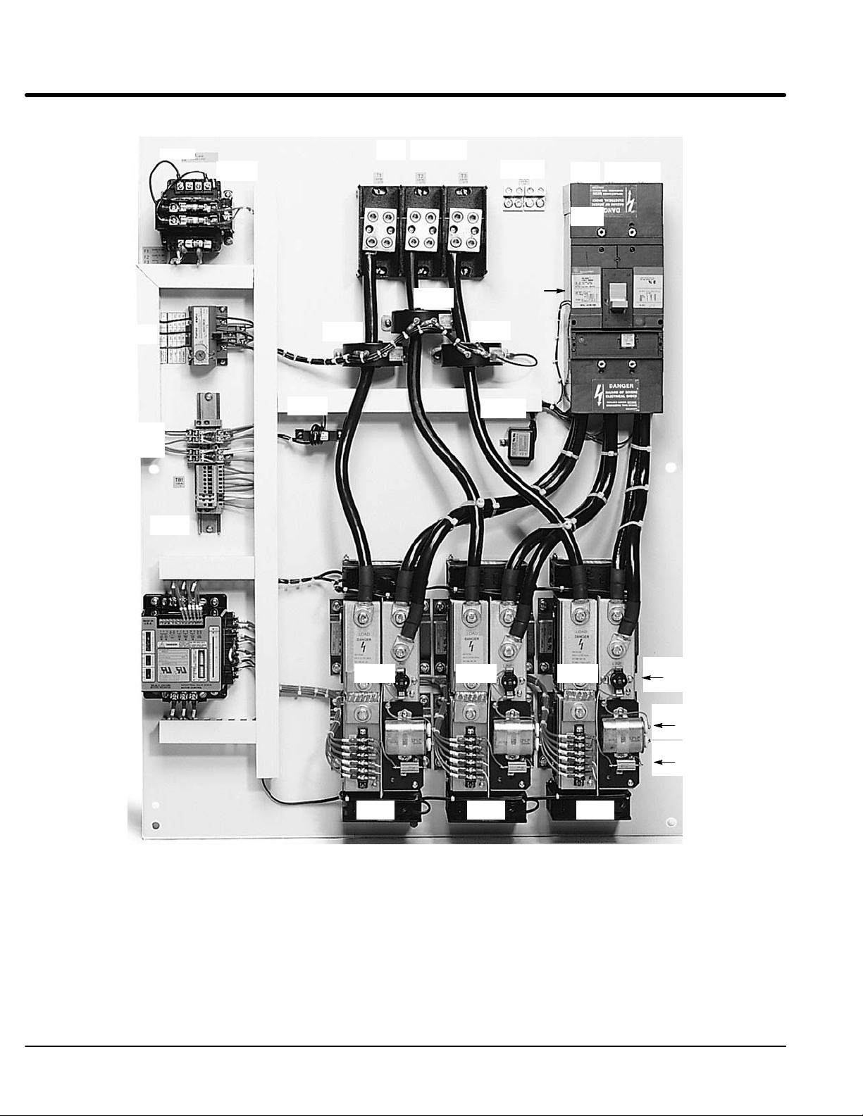
Figure 1-1 Layout and Identification
T1 T2 T3
GND
L1 L2 L3
F1
F2
F3
OL
R1
R2
TB1
CT1
CT2
CT3
CB
Shunt
Trip
CT4
MOV
LCM
Legend:
CB - Motor Circuit Protector or fusible disconnect
CPT - Control transformer (control voltage)
CT1, 2, 3, 4 - Current Transformer
F1, F2, F3 - Control transformer fuses
GND - Ground connection
LCM - Logic control module
MOV - Metal oxide varistors
OL - Overload relay (electronic)
PC1, 2, 3 - Power Cell
R1, R2 Control Relays
TB1, 2 - Terminal block
PC1 PC2 PC3
Fan Fan
Fan
Overtemperature
Switch
Snubber
Capacitor
Snubber
Resistor
1-2 General Information MN894
Page 9
Ramp
Mode
Select
User
Adjustment
Current
Transformer
x
x
Tachometer
Input
Close To
Run
12
13
C
U
R
R
E
N
T
4
5
RDD
CM
OC
TACH
CL
BP
RU
TU
CL
PT
RD
TD
CM
PF
MIN MAX
OFF ONS1
C
A
L
I
B
R
A
T
I
O
N
+
-
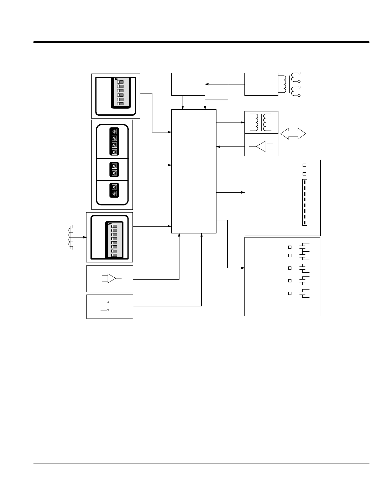
Figure 1-2 Logic Control Module Block Diagram
O
N
123456
1
2
3
4
5
6
OFF ONS2
S
T
A
R
T
S
T
O
P
R
U
N
O
N
12345678
1
2
3
4
5
6
7
8
Reset
Logic
Gates & Sync.
Logic &
Firing
Control
Power
Supply
+
-
Control Power
Overcurrent Trip
Current Monitor
Motor Power
Ramp End
Shunt Trip
Start/Run
Close To Run
115 /230 VAC
Power Input
Power Cell
Gates and
Cathodes
PWR
OC
M
400
O
T
300
O
R
200
C
U
R
100
R
E
N
T
0
%FLA
1
2
3
6
7
8
9
10
11
Status
Lights
Relay
Outputs &
Status
Legend:
BP - Bypass
CL - Current Limit
CM - Current Monitor
OC - Overcurrent
PF - Power Factor
PT - Pulse Time
RD - Ramp Down
RDD - Ramp Down Disable
RU - Ramp Up
S1 − Calibration Switch
TACH - Tachometer
TD - Torque Down
TU - Torque Up
General Information 1-3MN894
Page 10

Major Components (Refer to Figures 1-1 and 1-2).
Logic Control Module (LCM)
The LCM (Logic Control Module) operates in the voltage ramp mode or current limit
mode during ramp up and ramp down (if ramp down is selected). The LCM controls the
amount of current that the power cells deliver to the motor during ramp up and ramp
down. It uses gates and synchronous timing circuits to control the firing times of the
SCR’s in the power cells. The current transformer provides the LCM with motor current
information. The on board current calibration switches (S1-1 thru S1-8), place burden
resistors in parallel with the current transformer to calibrate the LCM to the correct FLA
(full load amperes) of the motor being used.
Current Transformer (CT1) provides starting, stopping and running current information to the LCM. This
information is used to control starting and stopping current, current limit, current monitor
and over current shutdown, power factor effect and motor current bar graph indicator.
(CT2) is required only for sizes 160 through 840 amps. It steps down current to match
primary rating of CT1 transformer.
8, 16 and 30 amp models - CT1 is mounted inside the LCM housing.
55 and 80 amp models - CT1 is mounted externally on the panel.
160 to 840 amp models - CT1 and CT2 are mounted externally on the panel.
CT1 ratio is 6000:1
CT2 ratio is 500:5 for 160, 250 and 420 Amp models.
CT2 ratio is 1000:5 for 600 and 840 Amp models.
Power Cells (PC) Power cells control the voltage delivered to the motor during ramp up and ramp down (if
ramp down is enabled). The LCM controls the duty cycle of the SCR’s in the power cells
(“on” time versus “off” time of each SCR). A power cell contains two silicon controlled
rectifiers (SCR’s). The SCR’s are solid state switches that are able to control large
amounts of current with a small amount of gate current supplied by the LCM.
8, 16 and 30 amp models - six SCR’s are mounted inside the LCM housing.
55 and 80 amp models - SCR’s are mounted in an isolated package containing two
SCR’s for each power cell. With this type of package, three power cells are mounted to a
single heat sink at ground potential. A temperature switch is provided in each cell to
protect the power cell from overheating.
160 to 840 amp models - Each SCR is a disk type package containing one SCR. Two
SCR’s are clamped between two heat sinks. A temperature switch is provided to protect
the SCR assembly from overheating. Heat sinks are mounted on an insulated base with
a terminal block and snubber network. The snubber network is a capacitor resistor series
circuit wired in parallel with the disk type SCR’s. The snubber network enhances the
electrical characteristics of the SCR’s and provides transient voltage protection. This
arrangement makes up one power cell. The power cell is at line potential for both line
and load terminals when line voltage is applied.
Protection Devices
Metal Oxide Varistors (MOV)
An MOV provides voltage surge protection. Voltage surges also called high voltage
spikes are caused by a number of sources. Short duration high voltage spikes caused by
starting and stopping other motor loads or switching On and Off capacitor banks may
appear on the incoming lines. Transients can occur from lightning storms or from other
lightly loaded devices on the same line, such as motors, transformers, or solenoids.
Electrical noise can be caused by lightning, arc welders and heat exchange equipment on
the same transformer bus line.
An MOVs provide protection by absorbing or clamping these transient energy levels.
High energy transients that exceed the MOV rating may damage the MOV and the
multipurpose starter.
1-4 General Information MN894
Page 11
Snubber Network 160 through 840 amp models only. A resistor and capacitor series circuit (snubber) is
wired in parallel with each disk type SCR. The RC network enhances the electrical
characteristics of the SCR and provides high voltage transient protection.
Shorted SCR Detection: If a shorted SCR condition is detected while starting, running or stopping, the SHUNT
TRIP contact will close and the SHUNT TRIP light will indicate the condition.
The SHUNT TRIP contact is used to open the circuit breaker via a shunt trip device.
Also, the shunt trip contact from the LCM module can be used to activate other circuit
interrupting device to remove the motor and control from the AC power line.
When a bypass contactor is used, the shunt trip circuit is disabled when the bypass
contactor is closed. This is accomplished by switching switch BP S2-6 On.
Over Current Shut Down: The control module has an over current detection circuit to trip and shut down the control
if motor current exceeds 450% FLA. To restart, open the Close To Run circuit, then close
it.
Current Monitor: When the motor is at speed (End of Ramp light is “ON”), the current monitor can detect
over current or overload motor conditions. This warning can alert an operator or be used
to stop a motor. It can also be used for indications of jams or blockages.
Motor Overload Protection: Class 30 motor overload protection is required to protect the control and the motor from
repetitive or extended starting conditions, as well as running during an overload condition.
Class 10 or 20 overloads may trip when starting high inertia loads or when operating in
current limit starting mode.
Over Temperature Switch: Power cells have over temperature switches to detect an overheating condition. The
switch is an isolated bimetallic, normally closed contact. If loss of cooling causes a power
cell to overheat, the temperature switch contact will open and shut down the control
circuit.
Note: When a temperature switch opens, the control shuts down. It must be reset
manually to restart the control.
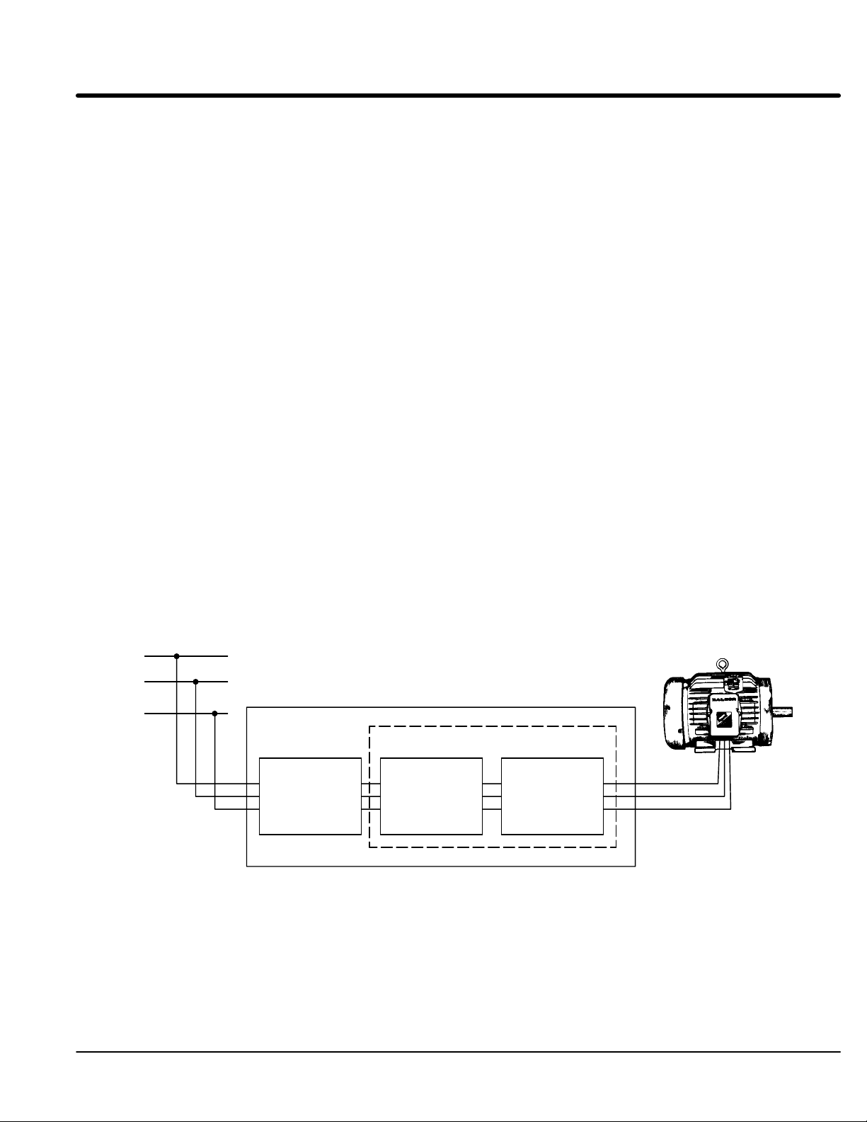
L1
L2
L3
Circuit
Breaker or
Fusible
Disconnect
Figure 1-3 Starter Diagram
Combination Starter
Non-Combination Starter
Soft
Start
Control
(Control only)
Overload
Relay
General Information 1-5MN894
Page 12

Configurations
Control Only: Soft start control, without motor overload protection or branch circuit
protection circuit breaker or fusible disconnect switch. Suitable for installation with a
series contactor or as a retrofit for an existing motor starter.
Non-combination Starter: Soft start control with motor overload protection, less branch
circuit protection circuit breaker or fusible disconnect switch. Installation with existing
branch circuit protection would use this configuration.
Combination Starter: Soft start control with motor overload protection and branch circuit
protection and branch circuit protection circuit breaker or fusible disconnect switch. Only
push buttons are required to complete the system. New installations with no existing
control equipment would use this configuration.
Bypass System, Control Only: Soft start control without overload protection and branch
protection. Includes a bypass contactor to shunt the power cells after the control is in the
full run mode to eliminate heat generation across the power cells. Allows installation in a
NEMA 4 or NEMA 12 enclosure.
Bypass System, Non-combination: Soft start control noncombination system with
motor overload protection, less branch circuit protection. Includes a bypass contactor to
shunt the power cells after the starter is in the full run mode to eliminate heat generation
across the power cells. Allows installation in a NEMA 4 or NEMA 12 enclosure.
Bypass System, Combination: Soft start control combination system with motor
overload protection and branch circuit protection circuit breaker or fusible disconnect
switch. Includes a bypass contactor to shunt the power cells after the starter is in the full
run mode to eliminate heat generation across the power cells. Allows installation in a
NEMA 4 or NEMA 12 enclosure.
Enclosures and Ventilation: Soft start controls are available in panel mount or in NEMA
type 1, 12, 3R enclosures. The control will generate approximately 3.3 watts of heat per
running ampere during operation. All factory supplied enclosures are designed to
dissipate this heat under maximum specified operating conditions. If the multipurpose
control is mounted in an enclosure not supplied by the factory, this heat dissipation must
be considered. Adequate ventilation or convection cooling should be provided unless a
bypass contactor is used.
Panel Mount: Soft start control mounted on a panel with provisions for wall or enclosure
installation.
NEMA Type 1 (IP23): Soft start control mounted in a ventilated NEMA type 1 panel
enclosure. Intended for indoor use primarily to provide a degree of protection against
contact with enclosed electrical components. Available for all sizes and configurations.
NEMA 12/3R (IP65/IP32): NEMA 12 enclosure provides protection from dust, dirt, oil
and water. NEMA 3R outdoor installation protects from rain, sleet and snow. A NEMA
12/3R is shipped as a NEMA 12 and to convert to NEMA 3R, remove the drain screw at
the bottom of the enclosure.
1-6 General Information MN894
Page 13

Limited Warranty
For a period of two (2) years from the date of original purchase, BALDOR will
repair or replace without charge controls and accessories which our
examination proves to be defective in material or workmanship. This
warranty is valid if the unit has not been tampered with by unauthorized
persons, misused, abused, or improperly installed and has been used in
accordance with the instructions and/or ratings supplied. This warranty is in
lieu of any other warranty or guarantee expressed or implied. BALDOR
shall not be held responsible for any expense (including installation and
removal), inconvenience, or consequential damage, including injury to any
person or property caused by items of our manufacture or sale. (Some
states do not allow exclusion or limitation of incidental or consequential
damages, so the above exclusion may not apply.) In any event, BALDOR’s
total liability, under all circumstances, shall not exceed the full purchase
price of the control. Claims for purchase price refunds, repairs, or
replacements must be referred to BALDOR with all pertinent data as to the
defect, the date purchased, the task performed by the control, and the
problem encountered. No liability is assumed for expendable items such as
fuses.
Goods may be returned only with written notification including a BALDOR
Return Authorization Number and any return shipments must be prepaid.
General Information 1-7MN894
Page 14

Safety Notice This equipment contains voltages that may be as high as 600 volts! Electrical shock can
cause serious or fatal injury. Only qualified personnel should attempt the start-up
procedure or troubleshoot this equipment.
This equipment may be connected to other machines that have rotating parts or parts
that are driven by this equipment. Improper use can cause serious or fatal injury. Only
qualified personnel should attempt the start-up procedure or troubleshoot this equipment.
PRECAUTIONS
WARNING: Do not touch any circuit board, power device or electrical connection before you
first ensure that power has been disconnected and there is no high voltage present
from this equipment or other equipment to which it is connected.
Electrical shock can cause serious or fatal injury.
WARNING: Be sure that you are completely familiar with the safe operation of this equipment.
This equipment may be connected to other machines that have rotating parts or
parts that are controlled by this equipment. Improper use can cause serious or
fatal injury. Only qualified personnel should attempt the start-up procedure or
troubleshoot this equipment.
WARNING: Be sure the system is properly grounded before applying power. Do not apply AC
power before you ensure that all grounding instructions have been followed.
Electrical shock can cause serious or fatal injury.
Caution: To prevent equipment damage, be certain that the electrical service is not capable
of delivering more than the maximum line short circuit current amperes listed for
the control rating.
Caution: Do not “Megger” test the motor while it is connected to the control. Failure to
disconnect motor will result in extensive damage to the control. The control is
tested at the factory for high voltage / leakage resistance as part of Underwriter
Laboratory requirements. Do not megger any part of the control.
Caution: Do not connect power factor correction capacitors to motor terminals. If power
factor correction capacitors are necessary, contact Baldor.
Caution: If a brake motor is used, the initial starting voltage may not be sufficient to release
the brake. It may be necessary to provide separate power for the brake and soft
start control.
Caution: Do not connect AC incoming line power to the Motor terminals T1, T2 and T3.
Connecting AC power to these terminals may result in damage to the control.
Caution: Do not supply any power to the “Close To Run” terminals. Power on these leads
can damage the control. Use a dry contact type that requires no external power to
operate.
Caution: Do not change the position of any switch while power is applied. Changing the
position of a switch during operation can damage the control and cause erratic
behavior of the load.
Caution: To prevent equipment damage, be certain that the electrical service is not capable
of delivering more than the maximum line short circuit current amperes rating.
Caution: This equipment is shipped as a multipurpose apparatus. Before power is applied,
the line voltage selection and the full load current calibration must be correctly set.
Failure to select the proper line voltage or to calibrate the full load current may
cause damage.
1-8 General Information MN894
Page 15

Section 2
Installation
Receiving, Inspection and Storage
When you receive your control, there are several things you should do immediately.
1. Observe the condition of the shipping container and report any damage
immediately to the commercial carrier that delivered your control.
2. Remove the control from the carton. Inspect for shipping damage and report
any damage immediately to your commercial carrier.
3. Verify that the part number of the control you received is the same as the part
number listed on your purchase order.
4. If the control is to be stored for several weeks before use, be sure that it is
stored in a location that is clean, dry and free from corrosives and
contaminants. Storage temperatures must not exceed 140°F (60°C).
Be sure to read an become familiar with the safety notices in Section 1 of this manual.
Failure to observe the product safety notices can result in injury or equipment damage.
If you have questions, please contact your Baldor distributor. Do not proceed unless you
understand the installation and operation requirements and safety notices.
Physical Location The location of the soft start control is important. It should be installed in an area that is
protected from direct sunlight, corrosives, harmful gases or liquids, dust, metallic
particles, and vibration. Exposure to these elements can reduce the operating life and
degrade performance of the control.
Several other factors should be carefully evaluated when selecting a location for
installation:
1. For effective cooling and maintenance, the control should be mounted vertically
on a flat, smooth, non-flammable vertical surface. Heat dissipation of 3.3 watts
per running FLA of the motor must be provided. All factory supplied enclosures
provided adequate heat dissipation.
2. If the control is mounted in an enclosure, sufficient air flow must be provided.
The fan or blower must be rated for at least 0.8 cubic feet per minute for each
ampere of motor FLA rating.
3. Keep high voltage and low voltage wiring separated. If the conduits must
cross, be sure that they cross at 90° angles only.
1. Motor overload protection is required for starters that do not have an overload
protection device.
2. The multipurpose soft starter is suitable for use on a circuit capable of
delivering no more than the short circuit A
3. A short circuit current and overcurrent devices are required for soft start
controls that do not have a circuit breaker or fusible disconnect switch.
AC Main Circuit
Protection Devices Be sure a suitable input power protection device is installed. Use the recommended circuit
breaker or fuses listed in Table 2-1. Wire sizes and protective device specifications are based
on the maximum output power rating of the control.
Power Disconnect A power disconnect should be installed between the input power service and the control for
a fail safe method to disconnect power. The control will remain in a powered-up condition until
all input power is removed from the control and internal voltages are depleted.
listed in Table 2-1.
RMS
Installation 2-1MN894
Page 16
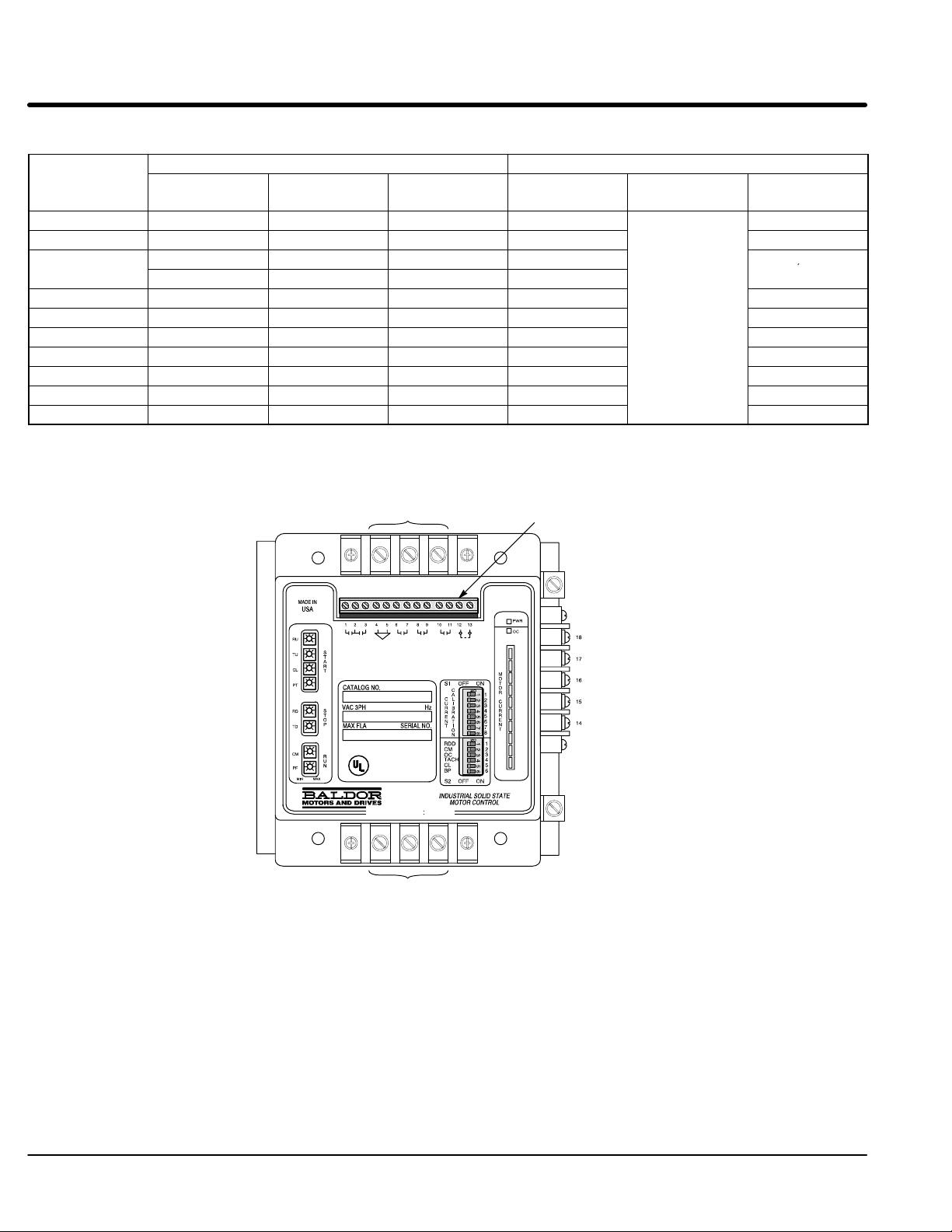
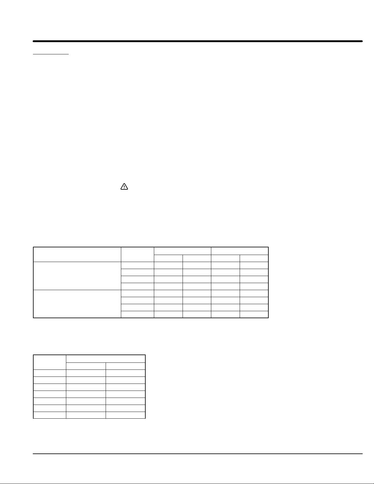
Table 2-1 Three Phase
Rati
,
SFLA
SGLA
SKLA
ng
(AMPS)
Amps Class
Fuse MCP (GE)
Short Circuit
A
RMS
Amps Type
8 100 J 5,000 20 5,000
16 100 J 5,000 20 5,000
30 200 J 5,000 50 5,000
100 RK1 5,000 50
55 175 J 42,000 100
SELA
80 175 J 42,000 100
160 400 RK5 100,000 300
250 400 RK5 100,000 300
420 800 L 100,000 600 42,000
600 800 L 100,000 600 42,000
840 1200 L 100,000 600 42,000
Note: Maximum recommended fuses/breakers are based on 25°C ambient, maximum continuous current.
Figure 2-4 Multipurpose Control Terminal Locations
(A) Line Input
L1 L2 L3
(C) Control Connections
(D) GND
Short Circuit
A
RMS
10,000
10,000
42,000
42,000
T1 T2 T3
(A) Motor Output Load
2-2 Installation MN894
(D) GND
Page 17
Installation
Starter Rati
Terminal
8, 16 and 30 AMPS
h 840 AMPS
AMPS
1. Mount the panel or enclosure to the mounting surface. The panel or enclosure must be
securely fastened to the mounting surface. Refer to the mounting dimensions in Section 6 of
this manual.
2. Ground the panel and control per NEC article 250 as well as state and local codes.
3. Use copper wire rated for at least 75°C. Refer to Figure 2-4 and Table 2-2 for wire size
recommendations.
4. Connect the incoming AC power wires from the power disconnect and/or protection devices to
L1, L2 and L3 terminals. Tighten each terminal as specified in Figure 2-4 and Table 2-2.
5. * Connect earth ground to the “GND” of the control. Be sure to comply with local codes.
6. Verify the input line voltage is correct.
7. For MA#−XX models, verify the line voltage selection jumpers on the LCM module are properly
set. For MB#−XX models, verify the control transformer primary taps are connected for the line
voltage applied.
8. Connect the three phase power leads of the AC motor to terminals T1, T2, and T3 of the Main
Circuit Terminals.
9. * Connect motor ground wire to the “GND” of the control. Be sure to comply with all applicable
codes.
Caution: Do not supply any power to the “Close To Run” terminals. Power
on these leads can damage the control. Use a dry contact type that
requires no external power to operate.
10. Connect the remaining control terminals as required for your installation. Refer to Figure 2-4 and
Table 2-2 for wire size and terminal torque specifications.
* Grounding by using conduit or panel connection is not adequate. A separate conductor of the
proper size must be used as a ground conductor.
Table 2-2 Recommended Wire Size and Tightening Torque
Torque Wire Size
lb-in Nm AWG mm
2
55 throug
ng
A 20 2.5 10-16 6-1.5
B 35 4 8 10
C 12 1.4 12-22 4-0.34
D 45 5.1 6-14 16-2.5
A Note 1 Note 1 Note 2 Note 2
B Note 1 Note 1 Note 2 Note 2
C 12 1.4 12-22 4-0.34
D 45 5.1 6-14 16-2.5
All wire sizes based on 75°C copper wire, 3% line impedance.
Higher temperature smaller gauge wire may be used per NEC and local codes.
Note1: Refer to the label on the equipment panel for line and load tightening torque values.
Note2: Line and Load wires sizes for 55 through 840 AMP models are as follows:
Wire Size
AWG mm
55 4 25
80 3 30
160 3/0 95
250 350 mcm 185
420 2x 300 mcm 2x 150
600 2x 500 mcm 2x 240
840 3x 500 mcm 2x 240
2
Installation 2-3MN894
Page 18

Non-Motor and Special Motor Applications
Non-motor load: The multipurpose control is designed to provide reduced starting voltage for standard
three phase induction motors. The control may also start non-motor loads for controlled
inrush current applications with resistive or inductive loads. Consult Baldor if the control
is to be used with a non-motor load.
Wye-Delta or The multipurpose control can replace an existing wye-delta or part winding starter.
Part Winding Starter: Begin by removing the existing contactors. Wire the motor in its “RUN” delta
configuration and connect the motor to the control. The control can be used as if it were
controlling a standard design B motor.
Wound Rotor Motors: Consult Baldor if the control is to be used with a wound rotor or slip ring type motor. This
type of load produces high starting torque with reduced starting current and speed. The
multipurpose control provides low starting current and low starting torque. The
multipurpose control can be used for applications that do not require high starting torque
and a continuous speed reduction.
High Slip Motors: The multipurpose control can be used with high slip motors, such as design D. These
motors are used with large inertial loads that require extended starting times. Reduced
starting voltage will reduce the starting current and extend the starting time. Long starting
times may require using slow trip overloads. However, the thermal capabilities of the
motor and control must be evaluated before extending the overload trip times.
Reversing Applications: For reversing applications, two multipurpose controls can be used or a reversing
contactor can be used. Consult Baldor for more information.
Multispeed Motors: Consult Baldor if the control is to be used with a multispeed motor. The control can
be used with a multispeed motor if a multispeed starter is connected between the control
and the motor. In this case, an additional MOV must be connected to the terminal side of
the control. Switching is normally done be auxiliary contacts from the multispeed starter
that are connected to the control circuit of the multipurpose control.
Motors on Grounded and A multipurpose starter should not be used with “Delta” or “Open” ground systems.
open delta systems: Without a proper ground, the circuit to detect a shorted SCR condition may malfunction or
may not be able to detect a shorted SCR condition.
2-4 Installation MN894
Page 19
Section 3
Operation
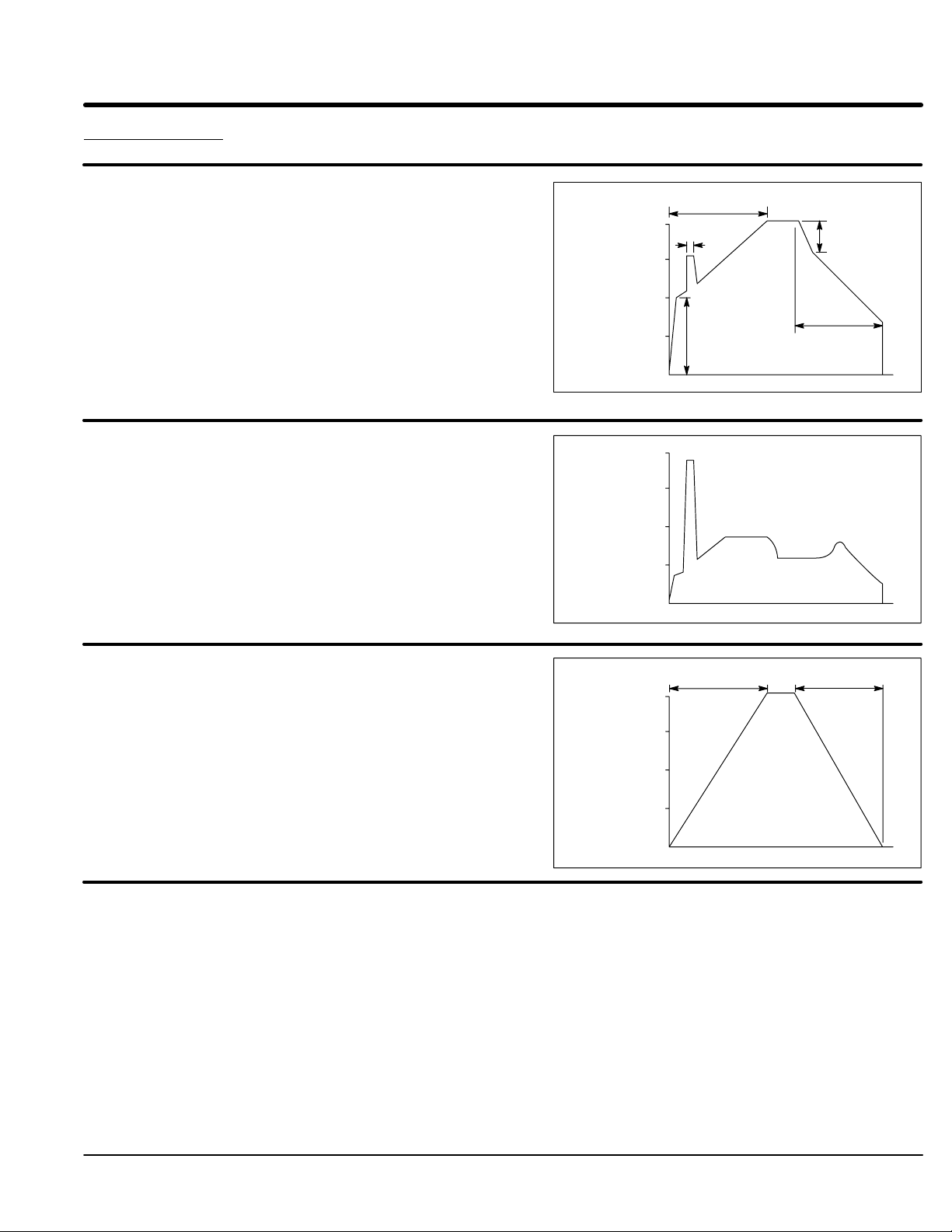
Types of Starting
Voltage Starting (S2-4 = OFF)
During start the initial voltage (TU) is set to a level where the
motor will begin to turn when power is applied. The ramp time
(RU) is adjustable to provide a smooth start. The pulse time
(PT) is used for high friction loads to break loose “frozen” loads
with up to 400% FLA.
If a ramp down function is needed, the initial voltage TD setting
is used to lower voltage to a level where the motor will begin to
slow down when the stop button is pushed. Ramp down (RD)
can only extend motor stopping time preventing sudden stopping
problems such as water hammer.
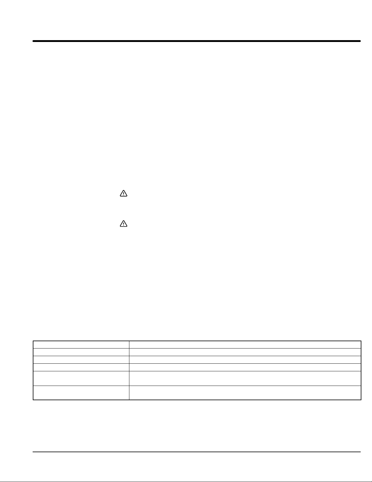
Current Limit Starting (S2-5 = ON)
If current limit starting is selected the starter will operate similar
to voltage starting. On high inertia loads such as chippers and
grinders the Current Limit (CL) setting is what determines the
starting time. The starter will provide that current regardless of
the ramp time setting. The CL setting must be high enough to
provide enough starting current in all starting conditions. Ramp
down (RD) can only extend motor stopping time preventing
sudden stopping problems such as water hammer.
Voltage
Ramp
% Line
Voltage
Current
Limit
% FLA
100
75
50
25
400
300
200
100
RU
PT
CL
TU
0
PT
0
Time
CL
Time
TD
RD
RD
Tach Feedback Starting (S2-4 = ON)
Tach feedback starting/stopping uses a 0-10 VDC Tach signal.
The control will provide voltage to the motor to generate a
smooth linear starting even under cycling load conditions. Ramp
down (RD) can only extend motor stopping time preventing
sudden stopping problems such as water hammer.
Tach
% Full
Speed
100
75
50
25
RUN
RU
0
Time
RD
Operation 3-1MN894
Page 20

Start Adjustments (Refer to Figure 3-1).
Ramp Up Ramp up time (RU) is adjustable from 3 to 50 seconds. RU adjusts the voltage ramp or
the tachometer starting ramp time. For voltage starting, RU adjusts the time it takes the
motor to reach full voltage. Actual acceleration time to full speed depends upon the
motor load and the setting of the additional start adjustments.
For Tach feedback starting, RU adjusts the motor starting time independent of the load
when used with a 0 to 10 VDC tachometer feedback signal. Smooth linear speed ramp
up with constant acceleration is achieved.
Torque Up The initial starting torque (TU) for ramp up is enabled only in the voltage ramp mode.
Usually set high enough to start the motor slowly turning the instant the start button is
pressed.
Pulse Time Starting pulse time (PT) is adjustable from 0 to 1.5 seconds in the voltage ramp mode.
When the start button is pressed, the initial motor voltage depends on the setting of TU.
One second after the start button is pressed, a pulse of approximately 400% FLA will
occur; the duration will depend upon the setting of PT.
Current Limit Current limit (CL) is adjustable from 75 to 400% of FLA. It can be used in both the
voltage and tachometer ramp modes of operation. When CL is enabled (S2-5=ON),
motor starting and stopping current will not exceed the set point of CL, except during PT.
Note: CL must be set high enough to allow the motor to start under maximum load
conditions. In the Tach feedback mode, CL will affect linearity and start and
stop times. The current is held at the CL limit until the motor current
decreases to less than the CL setting, regardless of the RU setting.
Figure 3-1
RU
TU
CL
PT
S
T
A
R
T
Stop Adjustments (Refer to Figure 3-2).
Ramp Down Ramp downtime (RD) extends the stopping time from 5 to 50 seconds. RD can be used
in both the voltage and tachometer modes.
In the tachometer mode, when used with a 0 to 10 VDC tachometer feedback signal, RD
will adjust the actual stopping time independent of motor load condition. Smooth linear
speed ramp down with constant deceleration is achieved.
In the voltage mode, RD adjusts the time it takes to reach minimum motor voltage and
turn off. The actual stopping time will depend on the motor load condition.
Note: Ramp down mode is not suitable for coasting or inertial loads that require
braking. Ramp down will only extend the stopping time.
Torque Down Torque down advance (TD) is adjustable from 0 to 100% advance. TD sets the initial
torque or voltage which ramp down starts and can be used in both voltage and
tachometer modes.
In ramp down mode, when the stop button is pressed, voltage will immediately decrease
to the set point of TD. Control will continue to ramp down to zero speed or voltage,
depending upon RD setting, then the control will turn off.
Figure 3-2
RD
TD
S
T
O
P
3-2 Operation MN894
Page 21

Run Adjustments (Refer to Figure 3-3).
Current Monitor Current monitor set point (CM) is adjustable from 50 to 400% FLA to monitor the running
current after the motor reaches the full run condition.
With CM enabled (S2-2=ON), if the running current exceeds the CM set point, the control
will shut down, the CUR MON contact will close, and the light will illuminate.
With CM disabled (S2-2=OFF), if motor current exceeds CM set point, the control will not
shut down, the CUR MON contact will close and the light will illuminate.
Power Factor Power factor effect (PF) is adjustable from 0 to 100%. PF is used to adjust the maximum
voltage applied to the motor under lightly loaded conditions to minimize motor current
with minimum motor load.
PF is enabled after the motor reaches full on condition.
PF should be turned off (CCW) if more than one motor is used with one control or if a
by-pass contactor is used.
Note: PF adjustment has no effect in bypass mode.
Figure 3-3
MIN MAX
R
U
N
CM
PF
Current Calibration Switch Refer to the multipurpose control Current Calibration Chart in Appendix A. Set switches
S1 to the motor FLA rating. Calibration is based on the motor nameplate full load
amperes (FLA), not necessarily actual running current. Motors with more than 6 times
locked rotor current may require a higher setting to start properly.
Operating Parameters Switch (Refer to Figure 3-4).
Switches S2-1 thru S2-6 select the operating modes that best fit the application.
S2-1 Ramp Down Disable (RDD).
In the “On” position: When the stop button is pressed, the control will immediately turn off.
User stop adjustments RD (ramp down time) and TD (ramp down initial starting torque)
are disabled.
In the “Off” position: When the stop button is pressed, the control will ramp down. In the
voltage mode of operation, ramp down time depends on RD and TD settings and the load
condition.
S2-2 Current Monitor (CM) “On” position: If the motor running current exceeds the Current Monitor (CM) setting, the
control will shut down. The shut down condition is indicated by the current monitor light
and the closure of the current monitor contact. The current monitor is typically used to
shut the control down when a jam occurs. To restart the control, press stop, then start; or
open the close to run circuit, then close it.
“Off” position: If motor running current exceeds the current monitor setting, the current
monitor light and contact will indicate this condition but the control will not shut down.
The current monitor can be used as an over and under current monitor.
S2-3 Over Current Indicator (OC).
“On” position: If an over current trip occurs (current exceeds 450% FLA), the control will
shut down and the condition will be indicated by the OC light and CM light and the
closure of the current monitor contact. To restart the control, press stop then start; or
open the close to run circuit, then close it.
“Off” position: An over current trip is indicated by the over current light and will not affect
the current monitor. The control will shut down.
Operation 3-3MN894
Page 22

S2-4 Tachometer and Voltage Ramp Select (TACH)
“On” position: The control is in the tachometer ramp mode during start and stop. Starting
and stopping times are independent of the load conditions. Ramp up (RU) is dependent
on the ramp up and current limit (CL) settings. RD is dependent on the RD and CL
settings.
Note: Current limit is disabled if S2-5 is “Off”. Operation in the tachometer mode
requires an isolated input tach signal of 0 to 10 volts DC with a 10 msec
response time or better. Tachometers with other voltage ranges may be used
with this control. Consult the factory for instructions.
If the tachometer full speed voltage is less than 10 volts DC, the starting and stopping
times will be proportionally shorter. For example, if the starting and stopping times are
adjusted to 20 seconds with a 0 to 10 volt DC tachometer signal; for a 0 to 5 Volt DC
tachometer signal with the same setting, the time will be 10 seconds.
“Off” position: The control is operating in the voltage ramp mode during start and stop (if
ramp down is selected using S2-1). All user settings for start, stop and run can be used
to set up the control to meet the application requirements. Starting and stopping times
are dependent on the actual load condition and control settings.
S2-5 Current Limit Enable (CL)
“On” position: Starting and stopping current will not exceed the setting of the current limit
setting, except during PT, if pulse start is being used. Current limit must be set high
enough to allow the motor to start under maximum load conditions.
“Off” position: Current limit is disabled. Maximum motor current is then limited by the
over current shutdown circuit to 450% FLA, preset at the factory.
S2-6 By-Pass Select (BP) “On” position: When the end of ramp contact closes, the circuit breaker shunt trip circuit
(the Shunt Trip contact on the Multipurpose control module) is disabled after the starter is
in the full run condition. This allows the use of a by-pass contactor without tripping the
circuit breaker when the power cells are bypassed.
“Off” position: the Shunt Trip circuit is enabled at all times.
Figure 3-4
O
N
RDD
CM
OC
TACH
CL
BP
123456
OFF ONS2
1
2
3
4
5
6
3-4 Operation MN894
Page 23

Control Connections (Refer to Figure 3-5).
CLOSE TO RUN Close to Run terminals 12 and 13. Close to run contact must be closed to initiate ramp
up and run. Close to Run contact must be opened to initiate ramp down to stop. Close to
run contact must be dry and electrically isolated contact. If a voltage is applied to these
terminals, the control may be damaged.
When the Close to Run circuit is closed, the Start/Run light will be on and the contact will
close. This normally open contact is typically used to seal in the start button circuit.
START/RUN Start/Run light and contact terminals 10 and 11. As long as the Closed to Run circuit
remains closed, the Start/Run light and contact will remain activated. This condition also
applies to an over current or a current monitor shutdown.
SHUNT TRIP Shunt Trip light and contact terminals 8 and 9. If the control detects a shorted SCR condition,
the shunt trip light will be on and the contact will close. The shunt trip contact is used to
operate a Shunt Trip device in the circuit breaker or similar disconnection means to remove
the motor and controller from the line should a shorted SCR condition occur.
The shunt trip circuit may also detect loss of phase or low voltage on a phase. The circuit
may not work properly on grounded delta systems or open delta systems. The Shunt Trip
circuit will trip when energized on single phase or an unbalanced line voltage.
RAMP END Ramp End light and contact terminals 6 and 7. In the voltage or the tachometer modes,
when the starting ramp is completed and the control is in the full run mode, the ramp end
light will be on and the contact will close. The starting current limit is then disabled and
CUR MON (running current monitor) is enabled.
Note: Since most loads do not require full voltage and torque to reach full speed,
when control is in the voltage ramp mode, the motor will reach full speed
before the ramp end contact and light are activated. Ramp end will only be
activated after the motor and control reach full voltage.
The ramp end contact can be used to turn on other equipment. The ramp end contact
can be used to close the bypass contactor to reduce heat dissipation of the SCRs.
TACH Tachometer input terminals 4 and 5. The TACH input is used in the tachometer mode
(S2-4=ON). The input required for TACH feedback is a 0 to 10 volt DC signal with a
maximum 10 ms response time.
MTR PWR Motor Power light and contact at terminals 2 and 3. Indicates that voltage and current are
supplied to the motor. If a current monitor or an over current shut down condition occurs,
the contact is deactivated and the light is turned off.
CUR MON Current Monitor light and contact terminals 1 and 2. A user adjusted monitor. Maximum
running current is adjustable from 50% to 400% FLA. Switch S2-2 controls the CM
monitor.
S2-2 “On” position: If motor current exceeds the CUR MON setting, the light will be on
and the contact will close. In addition, the motor power and ramp end LEDs will be off
and their contacts will open. The control will shut down. The Start/Run light will stay on
and the contact will remain closed. Typically used to shut down the control in case of a
mechanical jam. To restart a CUR MON shutdown, press stop then start; or open the
close to run circuit, then close it.
S2-2 “Off” position: If current exceeds the CUR MON setting, the light will be on and the
contact will close for the duration of the over current. The control will not shut down. In
this mode, the CUR MON monitor can be used as an over and under current monitor.
Figure 3-5
CUR
MON
PWR
+
−
CLOSE
TachMTR
End
TRIP
SHUNT
Ramp
START
/ RUN
TO RUN
Operation 3-5MN894
Page 24

Indicators
Power On The PWR light indicates that power is supplied to the internal power supply of the control.
WARNING: If the power light is not illuminated, it does not necessarily mean
that the line voltage is off. Electrical shock hazard may exist.
Measure the voltage at the line terminals before service.
Over Current OC over current shutdown LED. If the control shuts down due to an over current
condition (motor current is greater than 450% FLA), the OC light will be on. To restart the
control, press stop, then start; or open the close to run circuit, then close it.
Motor Current The Motor Current display is a 10 segment bar graph representation of motor current
from 0 to 400% FLA. Used to check ramp up, run and ramp down current conditions
while the control is in operation.
Summary of Start and Stop Sequences
To Start the Motor: Close 12 - 13 (Close to Run) and the following occurs:
1. 10 - 11 close to confirm start command.
2. 2 - 3 close when power is applied to motor. Ramp up cycle begins.
3. 6-7 close at the end of ramp up cycle.
To Stop the Motor: Open 12 - 13 (Close to Run) and the following occurs:
1. 10 - 11 open to confirm stop command.
2. 6-7 opens immediately.
3. 2 - 3 operation depend on ramp down mode selection:
With Ramp Down: 2 - 3 opens when ramp down is complete.
Without Ramp Down: 2 - 3 opens immediately.
Shunt Trip: During normal operation, detection of a shorted SCR, misfiring SCR will
cause the following:
1. 8 - 9 close immediately.
2. Shunt Trip light turns ON.
3. The shunt trip breaker is immediately tripped and all power is removed from the
control and motor.
Note: The shunt trip breaker will only trip if it is connected to the shunt trip contact at
terminals 8 & 9.
3-6 Operation MN894
Page 25

Section 4
Start-up
Safety Notice Be sure to read and understand all notices, warning and caution statements in Section 1
of this manual. If you have any questions about the safe operation of this equipment,
please contact your Baldor representative before you proceed.
Start-up Checklist
Recommended Equipment Volt meter (20kW per volt or better, true RMS meter).
Clamp on ammeter (5 times FLA full scale).
Adjustment wand (provided with multipurpose soft start control).
Overview The following adjustment procedures are examples and are intended to be used as a
guideline to match motor starting characteristics to the load. Actual loads may be
characterized by one or more of the examples. These procedures are intended to help
you design your own procedure for your specific application.
Keep in mind that reducing the starting current by one half will reduce the starting torque
by one fourth. This will cause the motor to take four times longer to reach full speed. In
situations where overloads tend to trip because of long starting times, increase the
starting current and decrease the ramp up time (RU) to help eliminate nuisance trips.
The potentiometer adjustments have a maximum span of 270°. Use the adjustment
wand (provided) to adjust these devices and do not force the adjustments beyond their
mechanical stops.
Caution: This equipment is shipped as a multipurpose apparatus. Before power is applied,
the line voltage selection and the full load current calibration must be correctly set.
Failure to select the proper line voltage or to calibrate the full load current may
cause damage.
Switches S1 and S2 as well as all potentiometer adjustments are not factory preset.
These will be set during the example procedures given in this section.
Before you apply Power
- Verify the installation procedure has been performed correctly.
- Know if your application is one of the “Non-motor and Special Motor
Applications” described in Section 2.
- Verify the wiring to the motor does not have any short circuits.
- Verify the motor is properly connected. Verify the voltage and full load amp
rating on the motor nameplate.
Note: A load must be connected to the control for testing. If the actual load cannot
be connected, connect any small motor temporarily for testing.
- Verify that the control transformer is properly jumpered for the line voltage at
your location. (MB#−XXX models).
- Verify that the control module jumper is correctly set for the line voltage.
(MA#−XXX models).
- Set S1 to the motor nameplate FLA value.
- Set S2 for the type of application.
- Set potentiometers as suggested.
- Verify the overload setting corresponds to the full load current range on the
calibration label.
After you apply Power
- Verify the input voltage to the starter and the 115VAC from the control
transformer (if a control transformer is installed).
- Verify the PWR light is on. (If not, refer to troubleshooting).
- Verify the shunt trip light is OFF. If it is ON, verify the motor is connected and
all three motor phases are present. If the motor is connected and the shunt trip
light is on, do not attempt to start the control. A short in the motor or wiring may
exist.
- Perform the starting procedure for your application.
Start-up 4-1MN894
Page 26

Quick Set-Up 1. Check continuity of the motor wiring and check for phase to phase and
phase to ground short circuits.
2. Connect the control wiring for your application.
(Refer to section 2 for wire size and torque specifications).
3. For MB#−XXX models, verify the control transformer is set for the line voltage.
For MA#−XXX models, verify proper voltage jumper selection on LCM models.
4. Calibrate S1. Refer to Appendix A for switch settings.
Voltage Ramp Starting - (Fans or lightly loaded motors)
5. Set for ramp up with ramp down as follows:
S2-1 = OFF Ramp down disable
S2-2 = OFF Current monitor
S2-3 = OFF Over current shut down
S2-4 = OFF Tachometer enable
S2-5 = OFF Current limit enable
S2-6 = OFF Bypass contactor
Set RU, TU, PT and PF fully CCW.
Set RD and RT at mid point.
6. Set for ramp up with no ramp down as follows:
S2-1 = ON Ramp down disable
S2-2 = OFF Current monitor
S2-3 = OFF Over current shut down
S2-4 = OFF Tachometer enable
S2-5 = OFF Current limit enable
S2-6 = OFF Bypass contactor
Set RU, TU, PT and PF fully CCW.
Note: If the control OC trips, use Current Ramp Starting.
7. Continue with step 14.
Current Ramp Starting - (High inertial loads)
8. Set for ramp up with ramp down as follows:
S2-1 = OFF Ramp down disable
S2-2 = OFF Current monitor
S2-3 = OFF Over current shut down
S2-4 = OFF Tachometer enable
S2-5 = ON Current limit enable
S2-6 = OFF Bypass contactor
Set RU, TU, PT and PF fully CCW.
Set RD and RT at mid point.
9. Set for ramp up with no ramp down as follows:
S2-1 = ON Ramp down disable
S2-2 = OFF Current monitor
S2-3 = OFF Over current shut down
S2-4 = OFF Tachometer enable
S2-5 = ON Current limit enable
S2-6 = OFF Bypass contactor
Set TU, PT, RD, TD and PF fully CCW.
Set RU fully CW.
Set CL to midpoint.
10. Continue with step 14.
4-2 Start-up MN894
Page 27
Tach Feedback Starting
11. Set for ramp up with ramp down as follows:
S2-1 = OFF Ramp down disable
S2-2 = OFF Current monitor
S2-3 = OFF Over current shut down
S2-4 = ON Tachometer enable
S2-5 = OFF Current limit enable
S2-6 = OFF Bypass contactor
Set RU, TU, PT and PF fully CCW.
Set RD and RT at mid point.
12. Set for ramp up with no ramp down as follows:
S2-1 = ON Ramp down disable
S2-2 = OFF Current monitor
S2-3 = OFF Over current shut down
S2-4 = ON Tachometer enable
S2-5 = OFF Current limit enable
S2-6 = OFF Bypass contactor
Set RU, TU, PT and PF fully CCW.
13. Continue with step 14.
WARNING: Be sure the system is properly grounded before applying power.
Do not apply AC power before you ensure that all grounding
instructions have been followed. Electrical shock can cause
serious or fatal injury.
WARNING: Improper operation of control may cause violent motion of the
motor shaft and driven equipment. Be certain that unexpected
motor shaft movement will not cause injury to personnel or damage
to equipment. Certain failure modes of the control can produce
peak torque of several times the rated motor torque.
14. Confirm the Close to Run contact is open.
15. Turn Power ON.
16. Close the Run contact.
17. The motor should just begin to rotate when power is applied and reach Ramp
End in a minimum starting time. The control is properly set if the motor starts
smoothly when power is applied and comes to speed as quickly as possible.
Be sure CL is set high enough so the motor can start with a full load. The
control is finished starting when the Ramp End light is ON.
18. If motor operation is not correct, perform one or more of the following
adjustments:
If the motor Remedy
Starts abruptly (jerks) Decrease TU by turning it CCW.
Starts too slowly Increase CL by turning it CW. Then decrease ramp time RU by turning it CW.
Starts too quickly Decrease CL by turning it CCW. Then increase ramp time RU by turning it CCW.
Is connected to a high inertial
load or a high slip motor is used
Is not starting properly Refer to detailed starting instructions for your application for more information on
It may be necessary to increase S1 setting to allow more motor current for faster
starting.
starting adjustments. Also, refer to start-up troubleshooting.
Start-up 4-3MN894
Page 28

Starting Instructions Choose one of the following examples that best matches your application. Read the
procedure and set the control according to the procedure or use the steps to develop
your own procedure.
Variable Load with Voltage Ramp (S2-2=OFF, S2−4=OFF)
Typically used for non-inertial loads, loads that increase with speed and changing loads,
such as axial fans and pumps.
1. Set RU, TU, PT, RD, TD and PF fully counterclockwise CCW).
2. Set CL and CM fully clockwise (CW).
3. Adjust TU clockwise sufficiently to start load slowly moving at moment of
switching.
4. Adjust RU clockwise to achieve desired starting time with normal load
conditions.
Note: Proceed to “Running Adjustment Procedure” if ramp down is not used.
5. Adjust TD clockwise sufficiently to cause the load to slow down soon after the
stop button is pressed, with normal load conditions.
6. Adjust RD clockwise to achieve desired stopping time with normal load
conditions.
Running Adjustment Procedure:
After adjusting the starting and stopping characteristics, current monitor/trip (CM)
and power factor adjustments can be made. If the power factor circuit is not used,
turn the PF adjustment fully counterclockwise.
Power Factor Correction Adjustment (PF):
1. Use an ammeter to measure motor running current.
2. With the motor at full speed, minimum load and the “Ramp End” light ON,
adjust PF clockwise to minimize running current without oscillation. If there is
no noticeable drop in current, repeat this step while measuring motor voltage.
Current Monitor/Trip (CM):
1. Set S2-2=OFF.
2. Press start and allow the motor to reach full speed and the “Ramp End” light to
turn ON.
3. Adjust CM to desired threshold by observing the “CUR MON” light.
4. The “CUR MON” contact can be used to indicates this threshold, or by setting
the S2-2=ON, the starter will shut down. Press stop to reset the shutdown and
trip condition.
Post Adjustment Check List:
1. Check fans for proper operation.
2. If bypass contactor is used, check that the contactor is closing at Ramp End.
3. Using a current probe, measure current on all three motor phases. Be sure the
current is balanced during ramp on, run and ramp down.
4. With the motor in run mode (Ramp End light “ON”), check phase current of all
three phases. Currents should be balanced and within nameplate FLA.
5. Measure the line voltage at the control during ramp up to ensure voltage does
not drop below minimum operating voltage.
4-4 Start-up MN894
Page 29

High Friction Load with Voltage Ramp (S2-2=OFF, S2-4=OFF)
Typically used for loads that require high breakaway torque and low acceleration torque;
i.e., conveyors in icy environment, equipment that resists starting due to lack of use,
traction loads, etc.
1. Set RU, TU, PT, RD, TD and PF fully counterclockwise (CCW).
2. Adjust PT clockwise sufficiently to start load slowly moving at moment of
switching.
3. Adjust TU clockwise sufficiently to keep load moving after starting pulse.
4. Adjust RU clockwise to achieve desired starting time with normal load
conditions.
Note: Proceed to “Running Adjustment Procedure” if ramp down is not used.
5. Adjust TD clockwise sufficiently to cause the load to slow down soon after stop
button is pressed, with normal load conditions.
6. Adjust RD clockwise to achieve desired stopping time with normal load
conditions.
Running Adjustment Procedure:
After adjusting the starting and stopping characteristics, current monitor/trip (CM)
and power factor adjustment can be made. If the power factor circuit is not used,
turn the PF adjustment fully counterclockwise.
1. Use an ammeter to measure motor running current.
2. With the motor at full speed, minimum load and “Ramp End” light on, adjust PF
clockwise to minimize running current without oscillation. If there is no
noticeable drop in current, repeat this step while measuring motor voltage.
Current Monitor/Trip (CM):
1. Press start and allow the motor to reach full speed and the “Ramp End” light to
turn on.
2. Adjust CM to desired threshold by observing the “CUR MON” light.
3. The “CUR MON” contact can be used to signal this threshold, or by setting the
S2-2=ON, the starter will shut down. Press stop to reset the shutdown and trip
condition.
Post Adjustment Check List
1. Check fans for proper operation.
2. If bypass contactor is used, check to ensure that the contactor is closing at
Ramp End.
3. Using a current probe, measure current on all three motor phases. Be sure the
current is balanced during ramp up, run and ramp down.
4. With the motor in run mode (Ramp End light “ON”), check phase current of all
three phases. Currents should be balanced and within nameplate FLA.
5. Measure the line voltage at the control during ramp up to ensure voltage does
not drop below minimum operating voltage.
Start-up 4-5MN894
Page 30

Inertial Load (S2-1=ON, S2-4=OFF, S2-5=ON)
Typically used on coasting and/or flywheel loads; i.e., chippers, centrifuges, compressors,
crushers, chillers, band saws, centrifugal fans and blowers.
Note: Ramp down and pulse start are not normally used with inertial loads.
1. Set TU, PT, RD, TD and PF fully counterclockwise (CCW).
2. Set RU approximately 90% clockwise.
3. Set CL to midpoint.
4. Set CM fully clockwise (CW).
5. Adjust CL sufficiently to allow motor to reach full speed in desired time with
maximum normal load.
Running Adjustment Procedure:
After adjusting the starting and stopping characteristics, current monitor/trip (CM)
and power factor adjustment can be made. If the power factor circuit is not used,
turn the PF adjustment fully counterclockwise.
Power Factor Correction Adjustment (PF):
1. Use an ammeter to measure motor running current.
2. With the motor at full speed, minimum load and the “Ramp End” light ON,
adjust PF clockwise to minimize running current without oscillation. If there is
no noticeable drop in current, repeat this step while measuring motor voltage.
Current Monitor/Trip (CM):
1. Set S2-2=OFF.
2. Press start and allow the motor to reach full speed and the “Ramp End” light to
turn ON.
3. Adjust CM to the desired threshold by observing the “CUR MON” light.
4. The “CUR MON” contact can be used to signal this threshold, or by setting
S2-2=ON, the starter will shut down. Press stop to reset the shutdown and trip
condition.
Post Adjustment Check List:
1. Check fans for proper operation.
2. If a bypass contactor is used, check that the contactor closes at ramp end.
3. Using a current probe, measure current on all three motor phases. Be sure the
current is balanced during ramp up, run and ramp down.
4. With the motor in run mode (ramp end light “ON”), check phase current of all
three phases. Currents should be balanced and within nameplate FLA.
5. Measure the line voltage at the control during ramp up to ensure voltage does
not drop below minimum operating voltage.
4-6 Start-up MN894
Page 31

Tachometer Mode (S2-4=ON, S2-5=OFF)
Typically used for changing loads that require consistent starting and stopping times,
independent of load condition, and pumping applications with severe head pressure to
reduce water hammer; i.e., pumps, conveyors, stackers and other material handling
equipment.
1. Set RU, TU, PT, RD, TD and PF fully counterclockwise (CCW).
2. Set CL and CM fully clockwise (CW).
3. Adjust RU and RD for desired ramp up and ramp down time. RD is only
effective with S2-1=OFF.
Running Adjustment Procedure:
After adjusting the starting and stopping characteristics, the current monitor/trip (CM)
and power factor correction circuit (PF) can be adjusted. If the power factor circuit is
not used, turn the PF adjustment fully counterclockwise.
Power Factor Correction Adjustment (PF):
1. Use an ammeter to measure motor running current.
2. With the motor at full speed, minimum load and SSC “Ramp End” light ON,
adjust PF clockwise to minimize running current without oscillation. If there is
no noticeable drop in current, repeat this step while measuring motor voltage.
Current Monitor/Trip (CM):
1. Set S2-2=OFF.
2. Press start and allow motor to reach full speed and the “Ramp End” light to turn
ON.
3. Adjust CM to the desired threshold by observing the “CUR MON” light.
4. The “CUR MON” contact can be used to signal this threshold, or by setting the
S2-2=ON, the starter will shut down. Press stop to reset the shutdown and trip
condition.
Post Adjustment Check List:
1. Check fans for proper operation
2. If a bypass contactor is used, check to ensure that the contactor closes at ramp
end.
3. Using a current probe, measure current on all three motor phases. Be sure the
current is balanced during ramp up, run and ramp down.
4. With the motor in run mode (ramp end light “ON”), check phase current of all
three phases. Currents should be balanced and within nameplate FLA.
5. Measure the line voltage at the control during ramp up to ensure voltage does
not drop below minimum operating voltage.
Start-up 4-7MN894
Page 32

Start-up Troubleshooting The Multipurpose Control module has 7 LEDs to help diagnose problems. There is a
summary of the functions and indications on pages 2-8 and 2-9. The Multipurpose starter
was tested under load with all SCR and electronic functions checked before shipping.
Note: To test the output of a soft starter a motor must be connected, even if it is a
1/2 HP motor on a 700 HP starter. Be careful not to start large motors
repeatedly without a cooling-down period.
No Power To The Motor
1. Verify the PWR light is “ON”.
2. Verify the Start/Run light is “OFF” and confirm terminals 12-13 on the control
module are open.
3. Give the starter a start command by closing the start contact connected to
terminals 12 and 13 (verify the Start/Run light is “ON”).
If the Start/Run light is not ON, turn off power and connect terminals 12 and 13
together with a small piece of wire as the jumper. Turn power ON. The
Start/Run light should come “ON” then the MTR PWR light should come “ON”
with power going to the motor.
If this sequence occurs using the jumper, check the start circuit as to why it did
not close the terminals 12-13. If this sequence did not occur, check the voltage
going to the logic control module.
Motor Does Not Start or Motor Does Not Come Up To Speed or
The Motor Overload Overload Trips
Adjust the “CL” to the max. If the motor is still not starting, set the S1 switch for
current calibration to the max. for that control size. Setting the S1 switch to a higher
setting only effects the calibration of light bar current indicator.
Test:
Try restarting the motor while adjusting the “CL” pot during starting. During starting,
check that the incoming voltage is not dropping. If it fails to start at the max. S1
setting, record the line voltage during starting, the motor data including the lock rotor
amps and contact your local Baldor office.
Circuit Breaker is Tripping − On Power Up
The circuit breaker supplied by Baldor is a motor circuit protector (MCP). It is also
called an adjustable magnetic only breaker. This means it will only trip during a
short circuit or instantaneous overcurrent condition. Baldor also adds a shunt trip
module to the breaker. Isolate the problem by disconnecting the shunt trip circuit.
Test for short circuit before re-energizing.
Test:
After the shunt trip circuit has been disabled, apply power. Check the shunt trip light,
if it is “ON” it is detecting a shorted SCR, a loss of phase, a lack of a load or a
grounded delta system. If the SCR’s have been replaced, they may be miswired.
Do not attempt to start until the problem is found.
4-8 Start-up MN894
Page 33

Circuit Breaker is Tripping − During Starting
If the shunt trip light comes “ON” during starting it may detect a weak input phase.
This is typical of grounded delta and open delta power systems. For proper
operation, a four wire WYE system is recommended.
If the shunt trip light is ON and it is determined that input power is correct and there
is a motor load; Then, disable the shunt trip circuit and do an SCR resistance test.
1. If the result of the SCR test shows the SCRE’s are in good condition, try
restarting. If the shunt trip light comes ON again, check the line voltage for a
weak phase.
2. If the SCR’s test bad, find out why they failed.
SCR’s fail due to high voltage. Is there a capacitor bank or a contactor in the
circuit? Check MOV’s and line voltage. MOV’s may be shorted or open due to
clearing of previous voltage spike.
SCR’s fail due to high current or high temperature.
a. Check the “T” leads for a phase to phase and phase to ground short
circuit.
b. Check the motor winding.
c. Check the voltage balance of power supply. If one leg is going to 25 - 30%
of nominal voltage or less during starting this will create high current on the
other phases.
d. Make sure the cooling fans are working and the ambient temperature is
within specification.
All Baldor starters are tested under load before shipping for proper SCR
performance.
OC light Comes ON Shutting “OFF” The Starter
1. If it trips during starting it may mean that S2-5 (CL) needs to be set to “ON”. If it
is already ON, be sure there are no capacitors or shorts in the motor leads.
2. If it trips when the Ramp End light comes ON, make sure that S2-2 (CM) is
“OFF” or current monitor level is set properly for a given load.
3. The control will turn OFF any time motor current exceeds 450% of the S1
current calibration setting.
Start-up 4-9MN894
Page 34

4-10 Start-up MN894
Page 35

Section 5
Troubleshooting
Safety Notice Be sure to read and understand all notices, warning and caution statements in Section 1
of this manual. If you have any questions about the safe operation of this equipment,
please contact your Baldor representative before you proceed.
Preliminary Checks In the event of trouble, disconnect all input power to the control and perform these
preliminary checks.
Power Off Checks
1. Check all connections for tightness and signs of overheating.
2. Check for cracked or damaged insulators and terminal blocks.
3. Ensure the correct setting of the overload relay.
4. Check the fuse in the control transformer.
5. Perform the SCR resistance test for all SCR’s.
6. If a shorted SCR is suspected, check for possible shorted connections, system
grounds or any other condition which may cause the short circuit condition.
7. Replace the SCR pack or power cell if no other causes were found. However,
installing a new SCR pack or power cell without determining the cause of failure
can result in repeated failure of the SCR’s. Refer to SCR replacement
procedure in this manual.
Blocking Voltage Check This check need only be performed if the resistance checks of the power cells or SCR
packs (55 and 80 amps) are inconclusive.
WARNING: Before power is applied to the control, be sure there is no danger to
personnel or equipment if the motor shaft rotates when power is
applied. A shorted SCR or damaged control can cause abnormal
operation of the motor.
1. Be sure power is off. Disconnect the load from the motor shaft if possible.
2. The T1, T2 and T3 motor leads should be connected to the control for this test.
3. Disconnect one of the wires at the shunt trip contact on the control to prevent
operation of the disconnect circuit during this test.
4. Apply power to the control.
5. Measure the voltage from the line terminal to the load terminal on each of the
power phases. The voltage should be about 0.58 times the input line to line
voltage. If the voltage on any power cell or SCR pack is significantly less than
this value, one or both SCR’s in the power cell or SCR pack may be shorted.
6. Remove all power to the control.
7. If a shorted SCR is suspected, check for possible shorted connections, system
grounds or any other condition which may cause the short circuit condition.
8. Replace the SCR pack or power cell if no other causes were found. However,
installing a new SCR pack or power cell without determining the cause of failure
can result in repeated failure of the SCR’s. Refer to SCR replacement
procedure in this manual.
Troubleshooting 5-1MN894
Page 36

SCR Tests If the SCR devices are suspected of failure, these tests can be used to test the SCR’s.
Inspection Be sure the physical condition of components is correct. Refer to Figure 5-1.
1. Be sure power is off.
2. Inspect power cell connections for tightness and signs of overheating.
3. Replace snubber capacitors if there is any sign of oil or fluid leaking.
Snubbers are not used on size 55 and 80 amp power cells.
4. Inspect SCR clamp insulator for cracks.
5. SCR clamps should be tightened evenly.
(Use clamp gauge available from Baldor).
6. Inspection and resistance test should be performed when system has
experienced:
Logic Control Module failure
MOV failure
Starting or running current imbalance
SCR replacement
Phase loss or single phasing
7. Heat sinks and insulating surfaces must be clean and unobstructed.
8. Size 55 and 80 amp power cells do not have snubber networks, SCR clamps or
insulating base.
Full Voltage Test After the motor reaches rated speed and the control is no longer in current limit, the
SCR’s turn full on and deliver full voltage to the motor. When power factor correction
(PF) is used, the control will reduce the voltage to the motor. For this reason, the PF
adjustment should be set to “OFF” during this test. Refer to Figure 5-1.
1. Set the PF adjustment should be set fully CW (OFF) during this test.
2. Turn power on. Wait for the motor to reach full speed.
3. With the control in the run mode, measure the voltage across the line side to
the load side on each control power cell or SCR pack. The voltage should be
about 2 to 20 VAC. The voltage reading will vary depending upon the motor
and the type of meter used. Voltage readings must be balanced on all three
phases.
4. If the voltage is higher across one or two power cells or SCR packs, not all
SCR’s are firing properly.
5. If all three cells or SCR packs have approximately the same voltage drop
across line to load when the motor is up to speed and motor current is
unbalanced, the cause is the motor or unbalanced line voltage.
5-2 Troubleshooting MN894
Page 37

Resistance Test Disconnect the power cell or SCR pack from all external wiring before you perform a
resistance check. Use an ohmmeter with 20,000 ohms per volt or greater impedance for
the resistance measurements. Refer to Table 5-1 and Figure 5-1.
1. Be sure power is OFF.
2. Remove all wiring from the power cell or SCR pack.
3. Sizes 55 and 80 amps have three SCR packs, one for each phase mounted on
a single ground potential heatsink. Check all three SCR packs. For example
L-GL must be measured from L1-GL1, L2-GL2 and L3-GL3. Circuit SA-SB
requires only one measurement.
4. Sizes 160 through 840 amps have a separate power cell for each phase.
Check all three power cells.
5. If any of the resistance measurements are incorrect, the power cell or SCR
pack should be repaired or replaced before operating the starter.
Table 5-1
Circuit Resistance
L-A
T-B
SA-SB
A-B Greater than 10k Ohms
L-GL
T-GT
Note: Results from the resistance measurements can be satisfactory and the power
cells may still be bad if the power cell is breaking down under voltage.
Less than 5 Ohms
5 to 100 Ohms
If resistance checks are not conclusive, perform Blocking Voltage Check and SCR Full
Voltage Test.
Figure 5-1 Power Cell Configurations
Troubleshooting 5-3MN894
Page 38

SCR Replacement
SCR Polarity Figure 5-2 shows the polarity and wire colors for correct SCR installation. It also shows
the locations of the tightening bars.
Figure 5-2 SCR Polarity
M160 / M250 M420 / M600 / M840
Cathode
Terminals GT, T, GL and L.
Gate (White wire)
Cathode (Red wire)
White wire to GL terminal,
Red wire to L terminal
White wire to GT terminal,
Red wire to T terminal
Anode Cathode
White wire to GL terminal,
Red wire to L terminal
AnodeCathode
Tightening Bar
Tightening Bar
Anode Cathode
White wire to GT terminal,
Red wire to T terminal
AnodeCathode
Terminals GT, T, GL and L.
SCR Pressure Gauge Figure 5-3 shows how the pressure gauge is used.
Figure 5-3 SCR Tightening Pressure Gauge
4°
3°
VE3000
VE2500
VE1000
VE2000
VE3500
VE5500
Calibration
SCR Mounting Kit Number
3°
VE3000
VE2500
VE1000
VE2000
VE3500
VE5500
Calibration
Tightening Bar
Tightening Bar
Tightening Bar
Tightening Bar
True Flat Surface Surface Deflection Measurement
Continued on next page.
5-4 Troubleshooting MN894
Page 39

With the SCR device installed with the tightening bar and bolts (Figure 5-2), tighten the
130 to
6.5 Ohms to
G
500k Ohms
bolts as follows: (see Figure 5-3)
1. Tighten the nuts evenly until finger tight.
2. Tighten bolts in 1/4 turn increments.
3. Use the SCR tightening pressure gauge and measure the deflection of the
Tightening bar. The middle and both ends of the gauge must be in solid contact
with the bar for an accurate reading. Correct pressure is indicated when the
gauge notch for the tightening kit number align.
Note: An anti-seize compound may be used on the bolt heads and threads to
reduce the torque required to obtain the correct mounting pressure.
Logic Control Module Resistance Test Refer to Figures 5-1 and 5-4.
This test will verify resistance measurements within the control.
1. Be sure power is OFF.
2. Disconnect the logic module from all external wiring before conducting
resistance checks.
3. Use an ohmmeter with 20,000 ohms per volt greater.
4. Compare the measured values with the values shown in Table 5-2.
Table 5-2
MB MB
Line/Load Gates Control Power Input
Circuit Resistance Circuit Resistance Circuit Resistance
L1-L2 L1-GL1 14-15
L1-L3 L2-GL2 16-17
L2-L3 L3-GL3
T1-T2
T1-T3
T2-T3
L1-T1 14-15 220 - 240
L2-T2 14-16 260 - 560
L3-T3 14-17 615 - 910
reater than
T1-GT1
T2-GT2 Control Power Input
T3-GT3 Circuit Resistance
6.5 Ohms to
8.5 Ohms MA
130 to
180 Ohms
14-18 1150 - 1180
Figure 5-4
Logic Control Module
L1 L2 L3
T1 T2 T3
Troubleshooting 5-5MN894
Page 40

Table 5-3 Troubleshooting Chart
MCP trips as it is
c osed (a so see
pg
(also
Shunt
Trip light comes
ON)
ON)
p
Shunt Trip light
thing wh
start button is
pressed
Mot
accelerates too
M
starting
Symptom Cause Corrective Action
Motor is not connected. Connect motor to T1, T2 and T3 of control.
MCP trips as it is
closed (also see
Shunt Trip light
comes ON)
MCP trips as the
motor is started
see
MCP trips after
the motor is
running (also see
Shunt Trip light
comes ON)
Starter does
no
Control does not
accelerate motor
to full speed
(Stalls)
Insufficient torque
available from
current limit CL.
Motor
accelerates too
slowly.
or
quickly.
Motor current
and voltage
oscillates after
start
otor is noisy or
vibrates when
en
.
ST contact on control is always closed. Repair or replace logic control module.
Improper input voltage. Obtain the correct source voltage at L1, L2 and L3.
Shorted SCR. Replace SCR or power cell.
Control transformer (if equipped) set for wrong
voltage.
MCP trip setting is too low. Increase MCP Trip setting.
Line voltage decreases during motor starting. Fix incoming power problem.
Motor or wiring is defective. Check terminal and motor wiring.
Capacitors on output of control. Remove capacitors or move to line side of control.
Logic control module is defective. Replace logic control module.
Improper current calibration. Verify S1 settings for motor nameplate FLA rating.
PF set too high. Reduce PF adjustment (rotate CCW).
Occasional line imbalance. Set S2-6 =ON to disable shunt trip while running.
Ground or motor fault. Check motor wiring.
S2-6=ON but no bypass contactor is installed. Check setting of S2-6. Should be Off.
No line voltage. Restore line voltage.
Overload is open. Reset overload.
No contact closure across terminals 12 and 13. Check start circuit.
Current trip occurs. Check S1 settings for correct current calibration.
Control module has no power. Check control transformer jumper.
CL set too low. Increase CL adjustment (rotate CW).
Line voltage decreases to less than minimum
operating voltage during motor starting.
Improper current feedback. Verify S1 settings for motor nameplate FLA rating.
CL set too low. Increase CL adjustment (rotate CW).
Ramp up (RU) time set too long. Decrease RU (rotate CCW).
Improper current feedback. Verify S1 settings for motor nameplate FLA rating.
Current limit (CL) set too high. Reduce CL (rotate CCW).
Ramp up time (RU) set too short. Increase RU (rotate CW).
Initial pulse time (PT) set too long. Reduce PT (rotate CCW).
Improper current feedback. Verify S1 settings for motor nameplate FLA rating.
Light or no load (is dependent on motor load).
A lightly loaded motor will reach full speed with
low starting current or voltage. Motor may
require the use of a tachometer.
Power factor correction set too high. Reduce PF setting (rotate CCW) until oscillation
Line voltage decreases to less than minimum
operating voltage during motor starting.
Single phasing due to an open phase. Check wiring and overload heaters.
Single phasing or unbalanced current due to a
non-firing SCR.
Single phasing or unbalanced current due to a
defective logic control module.
Defective motor. Check motor for shorts, opens or grounds.
Change tap connections for correct voltage.
Fix incoming power regulation problem.
Decrease TU, increase RU or install tachometer.
stops.
Fix incoming power regulation problem.
Check for shorted SCR and replace.
Repair or replace the logic control module.
5-6 Troubleshooting MN894
Page 41

Table 5-3 Troubleshooting Chart Continued
trips when starti
O
trips when
Shunt trip light
Symptom Cause Corrective Action
Incorrect heater size or setting. Check overload relay heater table in Appendix A.
Loose or burned heater. Tighten or replace heater.
Overload relay
verload relay
running
Motor decelerates
too quickly
(RDD=OFF)
Motor decelerates
too slowly
(RDD=OFF)
Erratic operation Loose connections. Check all connections.
Shunt trip light
comes ON
Long starting time. (high inertia loads may
require slow trip overloads.
ng
Mechanical failure within the load. Check machinery for binding or excessive loading.
Single phasing or unbalanced start circuit. Refer to “Motor is noisy or vibrates when starting”.
Excessive starting time (CL too low). Increase CL (rotate CW).
Incorrect heater size or setting. Check overload relay heater table in Appendix A.
Loose or burned heater. Tighten or replace heater.
Mechanical failure within the load. Check machinery for binding or excessive loading.
Single phasing or unbalanced start circuit. Refer to “Motor is noisy or vibrates when starting”.
Ambient temperature too high. Use ambient compensated overload relay.
Ramp down time (RD) set too short. Decrease RD (rotate CW).
Ramp down time (RD) set too long. Decrease RD (rotate CCW).
No load attached. Connect a motor to T1, T2 and T3 terminals.
Loss of phase or low input voltage to starter. Repair the input voltage problem.
Bad or misfiring SCR. Check resistance and replace SCR if defective.
Grounded delta power source. Shunt trip is not effective.
Note: If the MCP is tripping, remove the relay or disconnect the wires from terminals 8 and 9.
You can then determine if the MCP is tripping or if the module is opening the MCP.
Evaluate the thermal capabilities of the motor
before extending the overload trip time.
Troubleshooting 5-7MN894
Page 42
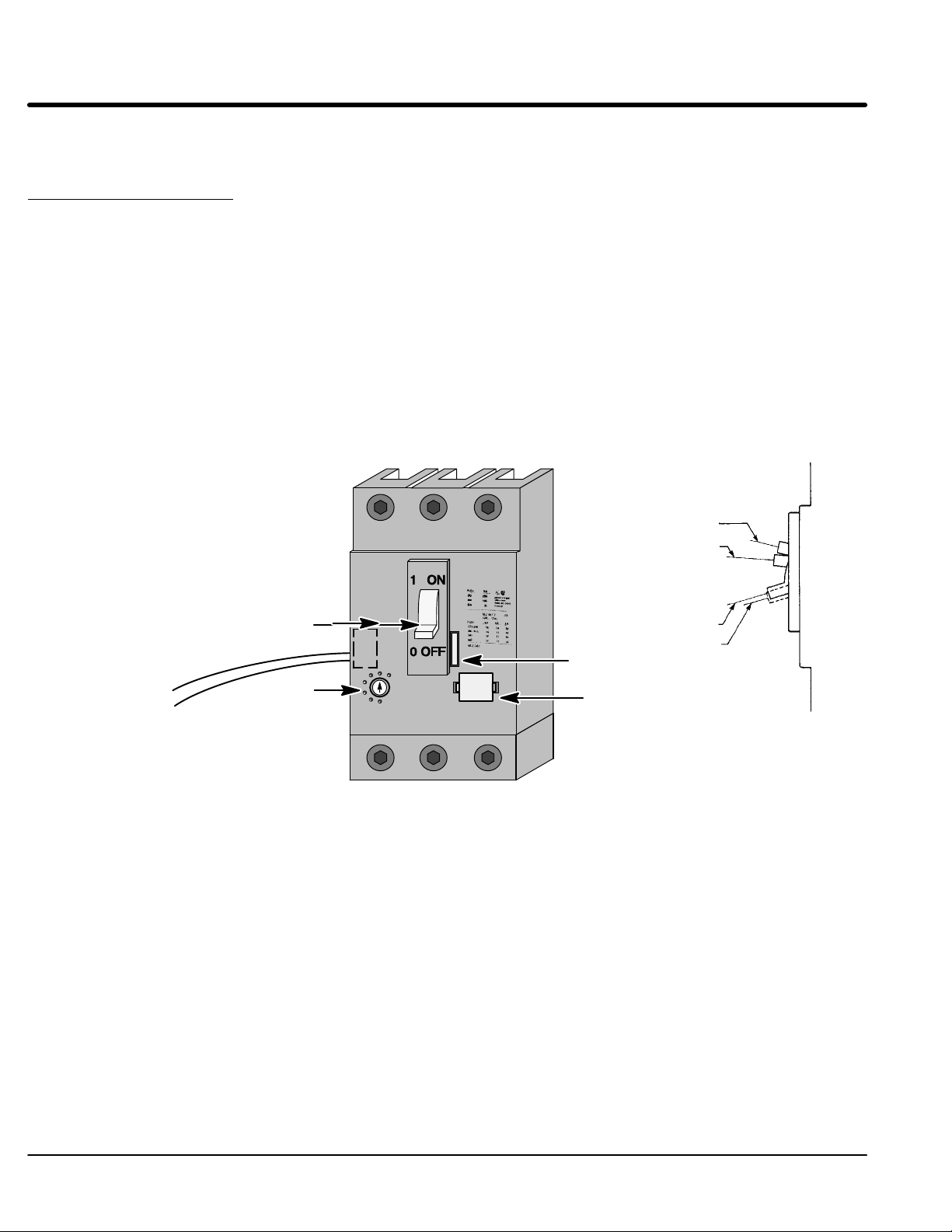
The control panel is intended to provide years of trouble free service with appropriate
cooling and protection from the elements. Should trouble occur, refer to the appropriate
control manual for control and motor troubleshooting information.
Reset the Circuit Breaker If the circuit breaker is tripped, it must be reset to restore power. The breaker is tripped if
the handle is in the “Tripped” position as indicated in Figure 5-5.
Before the breaker is reset, locate the source of electrical trouble.
1. Check for phase-to-phase and phase-to-ground shorts.
2. Check for loose connections at power connectors (L1, L2, L3 and Earth as well
as T1, T2, T3 and Motor Ground).
3. If all checks in steps 1 and 2 are OK, move the breaker handle all the way down
to the “Reset” position then move the handle to the “ON” position to restore
power. (In the “Reset” position, a click sound will be heard.)
4. Verify that an overcurrent condition is tripping the circuit breaker (not a shunt
trip). If the circuit breaker shunt trip was energized, the trip was caused by the
LCM soft start module shunt trip feature. Eliminate the cause of the shunt trip.
Figure 5-5 Magnetic Circuit Breaker
ON
Tripped
Shunt Trip Wires to
LCM soft start module
Handle
Shunt Trip Device
Trip Level
OFF
Reset
Manual Trip
Rating Plug
5-8 Troubleshooting MN894
Page 43
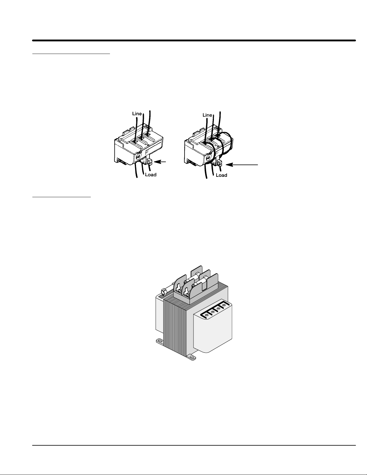
Reset an Overload Relay If the Overload relay is tripped, the tripped indicator (Reset Button of Figure 5-6) will be in
the “Tripped” position.
1. Verify that the overload condition has been cleared to allow restart.
2. Verify motor lead connections are tight.
3. Allow time for the overload to cool.
4. Press the “Reset Button” (Figure 5-6).
Figure 5-6 Overload Relay
Reset
Button
Reset
Button
Fuse Replacement If the control circuit voltage drops to zero volts, the control power transformer fuses
(Figure 5-7) should be inspected. If a fuse is opened, perform the following steps:
1. Check for line-to-ground short circuit condition and repair if necessary.
2. Check control wiring and control devices (timers, relays, terminal blocks, wire
terminations, etc.) for signs of damage, overheating, or loose connections and
repair if necessary.
3. Replace the fuse with the same fuse class, type, rating and interrupting
capacity.
Figure 5-7 Control Transformer with Fuses
Troubleshooting 5-9MN894
Page 44

5-10 Troubleshooting MN894
Page 45

Section 6
Specifications and Product Data
Identification
Three Phase Starters
M B
7 − 030 −
C B
− **
Control Type
M- Multipurpose
Control Group
A - Self powered logic control module
B - Logic control modules that require
115 or 230VAC.
Input Voltage Code
7- 208/230/460VAC (60Hz)
8- 230/460/575VAC (60Hz)
MA9- 220/380/415 (50Hz)
MB9- 380/400/415VAC (50Hz)
Ampere Rating
008- 8 Amp
016- 16 Amp
030- 30 Amp
055- 55 Amp
080- 80 Amp
160- 160 Amp
250- 250 Amp
420- 420 Amp
600- 600 Amp
840- 840 Amp
Bypass Contactor
0 − Normally not shown unless a
reduced size bypass is used.
A − First size smaller bypass.
B − Second size smaller bypass.
C − Third size smaller bypass.
Disconnect Size
0 − Normally not shown unless a
reduced size disconnect is used.
1 − Reduced size disconnect used:
i.e. 800 amp breaker on a 840amp
control instead of a 1000 amp
breaker.
Enclosure
A- Open
B- NEMA1 (IP32)
C- NEMA12 (IP65)
P- Panel Mount
Configuration
A - Combination with overload & circuit
breaker).
B - Non-combination (with overload).
C - Starter only.
D - Combination with fuse disconnect.
G - Bypass, combination starter.
H - Bypass, non-combination starter.
J - Bypass, starter only.
K - Bypass combination starter with
fuse disconnect.
Specifications and Product Data 6-1MN894
Page 46
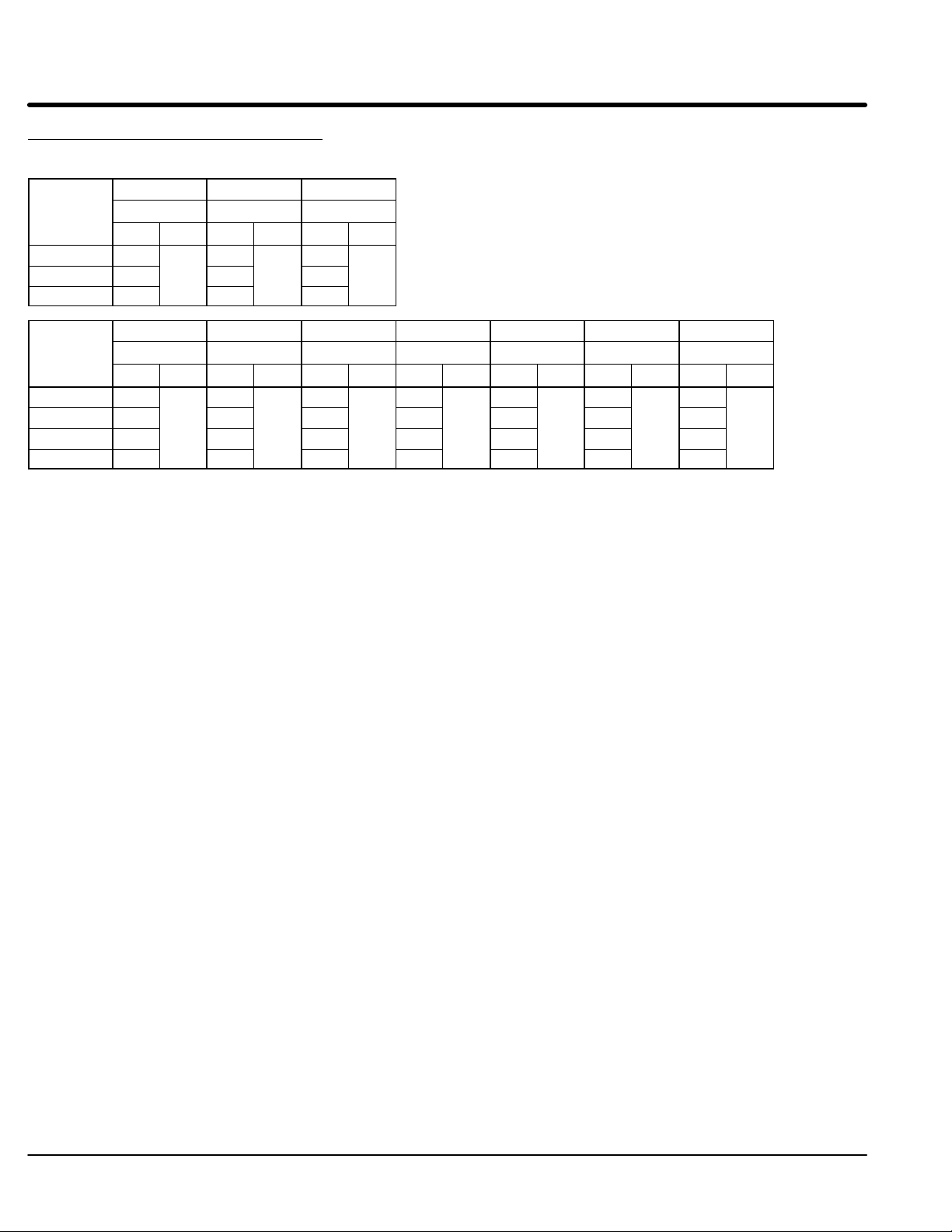
Multipurpose Control Specifications
VAC
VAC
556080
160
250
420
600
840
Three Phase Starters
Input
Voltage
VAC
3PH 60Hz
230 2 5 10
460 8
575 5 10 25
Input
Voltage
VAC
3PH 60Hz
208 15 25 50 75 150 200
230 20
460 40
575 50 75 150 250 400 600 800
MA7-008 MA7-016 MA7-030
MA8-008 MA8-016 MA8-030
HP I
MB7-055 MB7-080 MB7-160 MB7-250 MB7-420 MB7-600 MB7-840
MB8-055 MB8-080 MB8-160 MB8-250 MB8-420 MB8-600 MB8-840
HP I
HP I
C
10
8
HP I
C
30
16
HP I
C
20
HP I
C
60
125
30
C
C
HP I
100
200
C
HP I
150
350
C
HP I
250
500
HP I
C
300
700
C
IC = Continuous Current Rating
Input Ratings
Input Frequency 60/50 HZ ± 5%
Input Voltage +10% to −15% of Voltage Rating (except 575 VAC, max= 620VAC)
Overload Rating Continuous 115% of FLA; 400% for 30 seconds.
Phase Three Phase
Duty Continuous
Storage Conditions
Ambient Temperature: -4 to 140°F (-20 to 60 °C)
Humidity: 0 - 95% RH Non-Condensing
Operating Conditions
Enclosure: Open Panel (Indoor)
NEMA 1 (Industrial indoor, general purpose)
NEMA 12 (Industrial indoor, dust proof)
NEMA 4 (Outdoor)
The SCR’s generate about 3.3 watts of heat per running amp (motor FLA). If the control
is mounted in an enclosure, the installer must provide fans or blower with sufficient ventilation. Fan or blower should be rated for at least 0.8 CFM per ampere of motor FLA rating.
Baldor provided enclosures are designed to dissipate the heat from the SCR’s.
Humidity: 0 - 95% RH Non-Condensing
Control Heat Loss 3.3 Watt per running ampere of input current
Ambient Operating Temperature: 32-113°F (0 to +45 °C) enclosed
32-122°F (0 to +50 °C) open panel
Altitude: Sea level to 3300 Feet (1000 Meters)
Derate 1% per 330 Feet (100 Meters) above 3300 Feet
Derating Derate Amp rating 1% per 330 Feet (100 Meters) above 3300 Feet
Derate Amp rating 1.5% per °C over 45 °C to 55 °C Max
6-2 Specifications and Product Data MN894
Page 47

Control Specifications
Control Method 6 SCR’s connected in inverse parallel for full-wave 3 phase control
Peak Inverse Voltage 208/230 460 575
1200VAC minimum 1200VAC minimum 1600VAC
Start Time Adjustable range 3-50 seconds (current limit starting is not timed).
Stop Time Adjustable range 5-50 seconds (can only extend stop time).
Initial Torque Adjustable range: Starting 40-75%, Stopping 0-100%.
Current Limit (Selectable) Adjustable range 75-400% of FLA (full load amperes).
Pulse Time (Selectable) Adjustable range 0.1-1.5 seconds.
Current Monitor (Selectable) Adjustable range 50-400% of FLA. Causes contact closure or control shut
down when current level is reached (after starting).
Power Factor Adjustable for maximum reduced motor voltage, dependent on load.
Tach input (Selectable) 0-10VDC (maximum 10msec response time from tach).
Control module power 12VA at 115/230VAC ±5%
Status Contacts 125VAC at 0.5A, normally open. 60VA maximum rating.
Agency Listings UL (Underwriters Laboratory) and cUL (Canada)
Rated Storage Temperature: −40 °F to +140 °F (− 40 °C to +60 °C)
Note: A minimum inductance of 0.01 Henry is require for the SCR’s to commutate. Some large horsepower motors may
not have enough inductance and require adding inductors between the motor and control.
SCR Specifications
Overcurrent Over current shut down at 450% of motor FLA nameplate rating.
Shorted SCR detection Shunt Trip contract.
Protective Features
Overload Electronic overload class 30.
SCR Thermostat Trips on overtemperature of heatsink (sizes 55 amps and larger only).
Phase Loss Shunt Trip contact (sizes 55 amps and larger only) active only at power-up.
Voltage Transient MOV (metal oxide varistor).
Indicator LEDs
Power ON Ramp End
Over Current Shunt Trip
Current Monitor Start/Run
Motor Power Motor Current
MOV Devices Four varistors connected in wye configuration with one to ground.
MOV505EL
Max line volts=510VAC
Watts = 1.0
Max one time surge of 6500A @ 8V/20ms
MOV620E
Max line volts=625VAC
Watts = 1.0
Max one time surge of 6500A @ 8V/20ms
Specifications and Product Data 6-3MN894
Page 48

Wire Size & Tightening Torque Specifications
Terminal
Amps
Wire Size
Torque
Note1: Refer to the label on the
equipment panel for line and
load tightening torque values.
Note2: Refer to the label on the
equipment panel for ground
wire sizes
8, 16 Amp Control Only
Combination Starter and Non-Combination Starter
and Control Only
Line Input
(A)
Motor Output Load
(A)
(C)
Control Connections
(D)
GND
GND
(D)
OR
TB1
(B)
(B)
Control
Line Input
(C)
Motor Output Load
(D)
GND
GND
(D)
Wire Size Torque Specifications Size 8,16
Terminal Amps Wire Size Torque
(Identifier)
A 8, 16 10 - 16 20
B 30 8 - 18 35
55 4 Note 1
80 3 Note 1
160 3/0 Note 1
250 350 KCMIL Note 1
420 (2) 300 KCMIL Note 1
600 (2) 500 KCMIL Note 1
840 (3) 500 KCMIL Note 1
C All 12 - 22 12
D 8, 16, 30 6-14 45
55 Note 2 Note 1
80 Note 2 Note 1
160 Note 2 Note 1
250 Note 2 Note 1
420 Note 2 Note 1
600 Note 2 Note 1
840 Note 2 Note 1
AWG
lb-in
equipment panel for line and
load tightening torque values.
equipment panel for ground
wire sizes.
.
6-4 Specifications and Product Data MN894
Page 49

Mounting Dimensions
p
Open Panel
d
B
Dia
A
h
w
Open/Panel Dimensions
Amp
Rating
8 12.25 10.25 11.63 9.63 10.16 0.25 21.00 14.50 19.50 13.00 10.16 0.50 21.00 14.50 19.50 13.00 10.16 0.50
16 12.25 10.25 11.63 9.63 10.16 0.25 21.00 14.50 19.50 13.00 10.16 0.50 21.00 14.50 19.50 13.00 10.16 0.50
30 12.25 10.25 11.63 9.63 10.16 0.25 21.00 14.50 19.50 13.00 10.16 0.50 21.00 14.50 19.50 13.00 10.16 0.50
55 21.00 21.00 19.24 19.24 12.62 0.50 21.00 21.00 19.24 19.24 12.62 0.50 21.00 21.00 19.24 19.24 12.62 0.50
80 21.00 21.00 19.24 19.24 12.62 0.50 21.00 21.00 19.24 19.24 12.62 0.50 21.00 21.00 19.24 19.24 12.62 0.50
160 39.00 27.00 31.24 25.24 9.35 0.50 39.00 27.00 31.24 25.24 9.35 0.50 39.00 27.00 31.24 25.24 9.35 0.50
250 39.00 27.00 31.24 25.24 11.35 0.50 39.00 27.00 31.24 25.24 11.35 0.50 39.00 27.00 31.24 25.24 11.35 0.50
420 45.00 33.00 43.24 31.24 13.35 0.50 45.00 33.00 43.24 31.24 13.35 0.50 45.00 33.00 43.24 31.24 13.35 0.50
600 57.00 33.00 55.24 31.24 13.35 0.50 57.00 33.00 55.24 31.24 13.35 0.50 57.00 33.00 55.24 31.24 13.35 0.50
840 57.00 33.00 55.24 31.24 13.35 0.50 57.00 33.00 55.24 31.24 13.35 0.50 57.00 33.00 55.24 31.24 13.35 0.50
A B h w d Dia A B h w d Dia A B h w d Dia
Control Only Non-Combination Starter Combination Starter
Specifications and Product Data 6-5MN894
Page 50

Mounting Dimensions Continued
p
p
NEMA 1, 3R and 12
d
B
Dia
A
h
w
NEMA 1 Dimensions
Amp
Rating
8 14.00 12.00 11.00 11.00 11.35 0.28 24.00 16.00 21.88 11.00 11.35 0.31 24.00 16.00 21.88 11.00 11.35 0.31
16 14.00 12.00 11.00 11.00 11.35 0.28 24.00 16.00 21.88 11.00 11.35 0.31 24.00 16.00 21.88 11.00 11.35 0.31
30 14.00 12.00 11.00 11.00 11.35 0.28 24.00 16.00 21.88 11.00 11.35 0.44 24.00 16.00 21.88 11.00 11.35 0.31
55 24.00 24.00 25.24 18.00 12.62 0.44 24.00 24.00 25.24 18.00 12.62 0.44 24.00 24.00 25.24 18.00 12.62 0.44
80 24.00 24.00 25.24 18.00 12.62 0.44 24.00 24.00 25.24 18.00 12.62 0.44 24.00 24.00 25.24 18.00 12.62 0.44
160 42.00 30.00 37.24 24.00 9.35 0.44 42.00 30.00 37.24 24.00 9.35 0.44 42.00 30.00 37.24 24.00 9.35 0.44
250 42.00 30.00 37.24 24.00 11.35 0.44 42.00 30.00 37.24 24.00 11.35 0.44 42.00 30.00 37.24 24.00 11.35 0.44
420 48.00 36.00 49.24 30.00 13.35 0.44 48.00 36.00 49.24 30.00 13.35 0.44 48.00 36.00 49.24 30.00 13.35 0.44
600 60.00 36.00 61.24 30.00 13.35 0.44 60.00 36.00 61.24 30.00 13.35 0.44 60.00 36.00 61.24 30.00 13.35 0.44
840 60.00 36.00 61.24 30.00 13.35 0.44 60.00 36.00 61.24 30.00 13.35 0.44 60.00 36.00 61.24 30.00 13.35 0.44
A B h w d Dia A B h w d Dia A B h w d Dia
Control Only Non-Combination Starter Combination Starter
NEMA 12/3R Dimensions
Amp
Rating
8 20.00 16.00 21.24 10.00 11.35 0.44 20.00 16.00 21.24 10.00 11.35 0.44 24.00 20.00 25.24 14.00 11.35 0.44
16 20.00 16.00 21.24 10.00 11.35 0.44 20.00 16.00 21.24 10.00 11.35 0.44 24.00 20.00 25.24 14.00 11.35 0.44
30 20.00 16.00 21.24 10.00 11.35 0.44 20.00 16.00 21.24 10.00 11.35 0.44 24.00 20.00 25.24 14.00 11.35 0.44
55 30.00 24.00 31.24 18.00 11.35 0.44 30.00 24.00 31.24 18.00 11.35 0.44 30.00 24.00 31.24 18.00 11.35 0.44
80 30.00 24.00 43.24 18.00 11.35 0.44 30.00 24.00 31.24 18.00 11.35 0.44 30.00 24.00 31.24 18.00 11.35 0.44
160 42.00 36.00 43.24 30.00 9.35 0.44 42.00 36.00 43.24 30.00 9.35 0.44 42.00 36.00 43.24 30.00 9.35 0.44
250 42.00 36.00 43.24 30.00 11.35 0.44 42.00 36.00 43.24 30.00 11.35 0.44 42.00 36.00 43.24 30.00 11.35 0.44
420 60.00 36.00 61.24 30.00 13.35 0.44 60.00 36.00 61.24 30.00 13.35 0.44 60.00 36.00 61.24 30.00 13.35 0.44
600 60.00 48.00 61.24 42.00 13.35 0.44 60.00 48.00 61.24 42.00 13.35 0.44 60.00 48.00 61.24 42.00 13.35 0.44
840 60.00 48.00 61.24 42.00 13.35 0.44 60.00 48.00 61.24 42.00 13.35 0.44 60.00 48.00 61.24 42.00 13.35 0.44
A B h w d Dia A B h w d Dia A B h w d Dia
Control Only Non-Combination Starter Combination Starter
6-6 Specifications and Product Data MN894
Page 51

Connection Diagrams
MA Style 8, 16 and 30 AMP Combination and Non-Combination Starter and Control only
(Three Wire)
Start
Stop
(Hand - Off - Auto)
H
O
A
Two Wire
Control Device
(Two Wire)
Caution: Read Note
R
L1 L2 L3
Line Input
14
13
OL
TB1
9695
11
13
12
12
11
10
9
8
7
6
5
4
3
2
1
13
Close
To Run
Start /
Run
Shunt
Trip
Ramp
End
Tach
Input
MTR
PWR
CUR
MON
14
14
LCM
CB
Shunt
Trip
TB1
11
12
97
OL
98
Legend:
CB - Shunt trip motor circuit protector or fuse disconnect.
F1, F2 - Control transformer fuses.
F3 - Control branch circuit fuse.
LCM - Logic control module - type M.
MOV - Metal oxide varistors.
OL - Overload relay (electronic).
R - Run relay (customer provided).
TB1 - Terminal block.
X - Control transformer (control voltage).
11
TB1
AB
12
F3
14
13
X
F1
A
B
F2
A
B
115VAC
60Hz
50Hz
17
208
220
230
380
460
415
18
575
L1
N.A.
16
15
L2
L3
T1
T2
19
CT Input
20
T3
Caution:
To avoid equipment damage, jumper
terminal 14 to the appropriate terminal
that matches the line voltage.
LCM
Terminals 60Hz 50Hz
14-15
14-16
14-17
14-18
208VAC
230VAC
460VAC
575VAC
Voltage
220VAC
380VAC
415VAC
−−
CB
T1 T2 T3
To Motor
MOV
OL
Notes:
Control transformer must be properly connected for line voltage (see transformer nameplate).
Do not apply voltage to LCM terminals 12 and 13. Dry contact type only.
Motor must be connected before power is applied. Otherwise, the shunt trip will will trip the motor circuit
protector.
Tachometer is only required when LCM is used in Tach Feedback mode.
Motor circuit protector and this circuit are not provided with the non−combination starters, control only and fuse
disconnect versions.
Specifications and Product Data 6-7MN894
Page 52

Section 1
General Information
Connection Diagrams Continued
MB Style 8, 16 and 30 AMP Combination and Non-Combination Starter and Control only
(Three Wire)
Start
Stop
(Hand - Off - Auto)
H
O
A
Two Wire
Control Device
(Two Wire)
Caution: Read Note
R
L1 L2 L3
Line Input
11
TB1
CB
Shunt
Trip
12
97
OL
98
Legend:
CB - Shunt trip motor circuit protector or fuse disconnect.
F1, F2 - Control transformer fuses.
F3 - Control branch circuit fuse.
LCM - Logic control module - type M.
MOV - Metal oxide varistors.
OL - Overload relay (electronic).
R - Run relay (customer provided).
TB1 - Terminal block.
X - Control transformer (control voltage).
14
13
OL
TB1
9695
11
13
12
11
10
12
9
8
7
6
5
4
3
2
1
13
Close
To Run
Start /
Run
Shunt
Trip
Ramp
End
Tach
Input
MTR
PWR
CUR
MON
14
14
14
LCM
TB1
15
230VAC
15
11
F3
AB
115VAC
17
16
17
16
CT Input
20
19
14
13
12
CB
X
F1
A
B
F2
A
B
MOV
L1
L2
L3
T1
T2
T3
OL
T1 T2 T3
To Motor
Notes:
Control transformer must be properly connected for line voltage (see transformer nameplate).
Do not apply voltage to LCM terminals 12 and 13. Dry contact type only.
Motor must be connected before power is applied. Otherwise, the shunt trip will will trip the motor circuit
protector.
Tachometer is only required when LCM is used in Tach Feedback mode.
Motor circuit protector and this circuit are not provided with the non−combination starters, control only and fuse
disconnect versions.
6-8 Specifications and Product Data MN894
Page 53
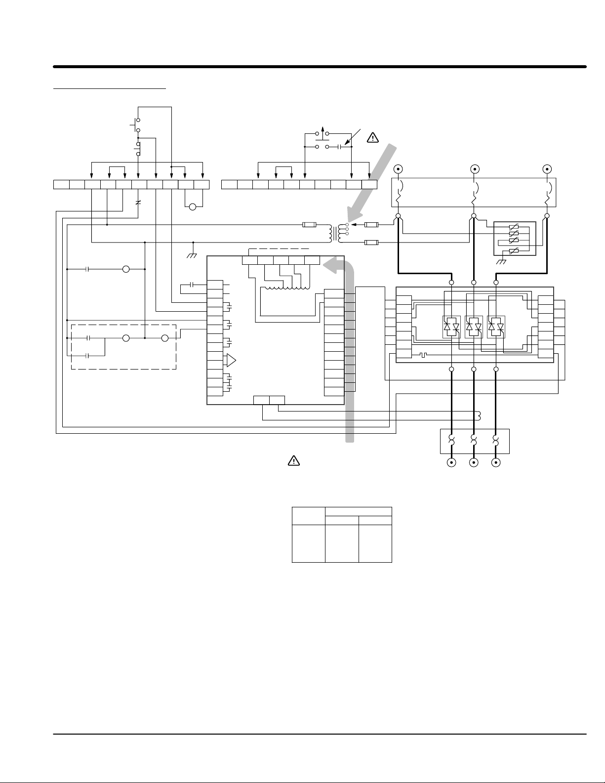
Section 1
General Information
Connection Diagrams Continued
MA Style 55 and 80 AMP NEMA 1 and Panels Combination and Non-Combination Starter and Control only
Start
(Three Wire)
Stop
(Hand - Off - Auto)
H
O
A
Two Wire
Control Device
Caution: Read Note
Line Input
L1 L2 L3
2
7864531
95
OL
96
9
R1
13 14
10
2
TB1TB1
Close
To Run
Start /
Run
Shunt
Trip
Ramp
End
Tach
Input
MTR
PWR
CUR
MON
15
14
LCM
CT Input
19
95
R1
CF
R1
12 8
13
12
11
10
9
R2 CB
95
97 98
OL
Shunt Trip
13 14
R2
8
7
6
5
4
3
2
1
Legend:
CB - Shunt trip motor circuit protector or fuse disconnect.
CF - Power cell cooling fan.
CT1 - LCM current transformer.
F1, F2 - Control transformer fuses.
F3 - Control branch circuit fuse.
LCM - Logic control module - type M.
MOV - Metal oxide varistors.
OL - Overload relay (electronic).
PC1 - SCR power cell.
R1 - Run relay, DPDT.
R2 - Shunt trip relay, DPDT.
S - SCR overtemperature switch.
SCR - Silicon controlled rectifier.
TB1 - Terminal block.
X - Control transformer (control voltage).
9
10
X
F1
B
F2
A
B
L1
L2
L3
60Hz
50Hz
ABF3A
115VAC
17
208
220
230
380
415
460
18
575
N.A.
16
7864531
GL1
GL2
GL3
GT1
GT2
GT3
T1
T2
T3
20
Caution:
To avoid equipment damage, jumper
terminal 14 to the appropriate terminal
that matches the line voltage.
LCM
Terminals 60Hz 50Hz
14-15
14-16
14-17
14-18
208VAC
230VAC
460VAC
575VAC
Voltage
220VAC
380VAC
415VAC
−−
SA
CB
MOV
PC1
L3
L2
L1
SCR SCR SCR
T1
T2
T3
S
GL3
GL2
GL1
GT3
GT2
GT1
SB
CT1
OL
T1 T2 T3
To Motor
Notes:
Control transformer must be properly connected for line voltage (see transformer nameplate).
Do not apply voltage to LCM terminals 12 and 13. Dry contact type only.
Motor must be connected before power is applied. Otherwise, the shunt trip will will trip the motor circuit
protector.
Tachometer is only required when LCM is used in Tach Feedback mode.
Motor circuit protector and this circuit are not provided with the non−combination starters and fuse disconnect
versions.
Specifications and Product Data 6-9MN894
Page 54

Section 1
General Information
Connection Diagrams Continued
MB Style 55 and 80 AMP NEMA 1 and Panels Combination and Non-Combination Starter and Control only
Start
(Three Wire)
Stop
(Hand - Off - Auto)
H
O
A
Two Wire
Control Device
Caution: Read Note
Line Input
L1 L2 L3
2
7864531
95
OL
96
9
R1
13 14
10
2
TB1TB1
Close
To Run
Start /
Run
Shunt
Trip
Ramp
End
Tach
Input
MTR
PWR
CUR
MON
15
14
14
LCM
CT Input
19
95
R1
CF
R1
12 8
13
12
11
10
9
R2 CB
95
97 98
Shunt Trip
OL
13 14
R2
8
7
6
5
4
3
2
1
Legend:
CB - Shunt trip motor circuit protector or fuse disconnect.
CF - Power cell cooling fan.
CT1 - LCM current transformer.
F1, F2 - Control transformer fuses.
F3 - Control branch circuit fuse.
LCM - Logic control module - type M.
MOV - Metal oxide varistors.
OL - Overload relay (electronic).
PC1 - SCR power cell.
R1 - Run relay, DPDT.
R2 - Shunt trip relay, DPDT.
S - SCR overtemperature switch.
SCR - Silicon controlled rectifier.
TB1 - Terminal block.
X - Control transformer (control voltage).
ABF3A
115VAC
17
16
230VAC
15
17
16
20
7864531
9
10
CB
MOV
S
GL3
GL2
GL1
GT3
GT2
GT1
SB
L1
L2
L3
GL1
GL2
GL3
GT1
GT2
X
F1
B
F2
A
B
PC1
L3
L2
L1
SCR SCR SCR
T1
T2
T3
SA
GT3
T1
T2
T3
CT1
OL
T1 T2 T3
To Motor
Notes:
Control transformer must be properly connected for line voltage (see transformer nameplate).
Do not apply voltage to LCM terminals 12 and 13. Dry contact type only.
Motor must be connected before power is applied. Otherwise, the shunt trip will will trip the motor circuit
protector.
Tachometer is only required when LCM is used in Tach Feedback mode.
Motor circuit protector and this circuit are not provided with the non−combination starters and fuse disconnect
versions.
6-10 Specifications and Product Data MN894
Page 55

Section 1
General Information
Connection Diagrams Continued
NEMA 1 & Panel Mounted Size 160−840 AMP Control Only
Enclosure
Fan
2
TB1
7864
9
TB1
10
R1
13 14
ABF3A
X
115VAC
Enclosure
Fan
2
31
(Three Wire)
Start
Stop
OL
5
(Hand - Off - Auto)
H
O
A
Two Wire
Control Device
OL
10
7864531
9
Caution: Read Note
L1 L2 L3
F1
B
F2
A
B
(Line Switched)
Enclosure
Fan
2
TB1
OL
M
115VAC
Line Starter
Control Circuit
7864531
9
10
Line Input
MOV
R1
9
5
CF
CF
CF
R1
12 8
13
12
11
10
9
8
7
6
5
4
3
2
1
Legend:
CF - Power cell cooling fan.
CS - Snubber capacitor.
CT1 - LCM current transformer.
CT2 - Primary current transformer.
F1, F2 - Control transformer fuses.
F3 - Control branch circuit fuse.
LCM - Logic control module - type M.
M MOV - Metal oxide varistors.
LCM
CT Input
19
17
16
PC1/L
L1
PC2/L
L2
PC3/L
L3
GL1
GL2
GL3
GT1
GT2
GT3
T1
T2
T3
PC1/GL
PC2/GL
PC3/GL
PC1/GT
PC2/GT
PC3/GT
PC1/T
PC2/T
PC3/T
L1
GL1
GT1
T1
S1A
S1B
20
14
Close
To Run
Start /
Run
Shunt
Trip
Ramp
End
Tach
Input
MTR
PWR
CUR
MON
15
OL - Overload relay (electronic).
PC1,2,3 - SCR power cells.
R1 - Run relay, DPDT.
RS - Snubber resistor.
S - SCR overtemperature switch.
SCR - Silicon controlled rectifier.
TB1 - Terminal block.
X - Control transformer (control voltage).
PC1
L
GL
GT
T
SA
SB
Line
SC
RS
S
Load
PC2
L2
L
GL2
GL
GT2
GT
T2
T
S2A
SA
S2B
SB
Line
SC
RS
S
Load
CT1
CT2
T1 T2 T3
CT1
To Motor
MBX140 = 8 Turns
MBX160 = 8 Turns
MBX250 = 4 Turns
MBX420 = 4 Turns
MBX600 = 4 Turns
MBX840 = 4 Turns
4 Turns (3 Loops)
PC3
L3
L
GL3
GL
GT3
GT
T3
T
S3A
SA
S3B
SB
Line
SC
RS
S
Load
Notes:
Control transformer must be properly connected for line voltage (see transformer nameplate).
Do not apply voltage to LCM terminals 12 and 13. Dry contact type only.
Number of cooling fans depends on the FLA rating.
Tachometer is only required when LCM is used in Tach Feedback mode.
MOVs are connected in parallel for greater energy absorption for control sizes above 420Amp FLA.
For factory supplied enclosure fans only.
Specifications and Product Data 6-11MN894
Page 56

Section 1
General Information
Connection Diagrams Continued
NEMA 1 & Panel Mounted Size 160−840 AMP Combination & Noncombination
(Three Wire)
Enclosure
Fan
(Hand - Off - Auto)
H
O
A
Two Wire
Control Device
Start
Enclosure
Stop
2
TB1
Fan
2
7864531
95
OL
96
9
R1
13 14
10
ABF3A
TB1
115VAC
R1
9
5
R2 CB
95
97 98
OL
CF
CF
CF
Shunt Trip
13 14
R2
R1
12 8
13
12
11
10
9
8
7
6
5
4
3
2
1
14
Close
To Run
Start /
Run
Shunt
Trip
Ramp
End
Tach
Input
MTR
PWR
CUR
MON
15
LCM
19
16
CT Input
20
17
L1
L2
L3
GL1
GL2
GL3
GT1
GT2
GT3
T1
T2
T3
Legend:
CB - Shunt trip motor circuit protector or fuse disconnect..
CF - Power cell cooling fan.
CS - Snubber capacitor.
CT1 - LCM current transformer.
CT2,3,4 - Overload current transformer.
F1, F2 - Control transformer fuses.
F3 - Control branch circuit fuse.
LCM - Logic control module - type M.
MOV - Metal oxide varistors.
OL - Overload relay (electronic).
PC1,2,3 - SCR power cells.
R1 - Run relay, DPDT.
R2 - Shunt trip relay, DPDT.
RS - Snubber resistor.
S - SCR overtemperature switch.
SCR - Silicon controlled rectifier.
TB1 - Terminal block.
X - Control transformer (control voltage).
Caution: Read Note
10
8
7
64531
9
Line Input
L1 L2 L3
CB
X
F1
B
F2
A
B
MOV
PC1/L
PC2/L
PC3/L
PC1/GL
PC2/GL
PC3/GL
PC1/GT
PC2/GT
PC3/GT
PC1/T
PC2/T
PC3/T
PC1
L1
L
GL1
GL
GT1
GT
T1
T
S1A
SA
S1B
SB
CT2
Line
SC
RS
S
Load
PC2
L2
L
GL2
GL
GT2
GT
T2
T
S2A
SA
S2B
SB
Line
SC
RS
S
Load
PC3
L3
L
GL3
GL
GT3
GT
T3
T
S3A
SA
S3B
SB
Line
SC
RS
S
Load
CT3 CT4
OLOL
OL
CT1
T1 T2 T3
CT1
To Motor
MBX140 = 8 Turns
MBX160 = 8 Turns
MBX250 = 4 Turns
MBX420 = 4 Turns
MBX600 = 4 Turns
MBX840 = 4 Turns
4 Turns (3 Loops)
Notes:
Control transformer must be properly connected for line voltage (see transformer nameplate).
Do not apply voltage to LCM terminals 12 and 13. Dry contact type only.
Number of cooling fans depends on the FLA rating.
Tachometer is only required when LCM is used in Tach Feedback mode.
MOVs are connected in parallel for greater energy absorption for control sizes above 420Amp FLA.
Motor circuit protector and this circuit are not provided with the non−combination starters and fuse disconnect
versions.
For factory supplied enclosure fans only.
6-12 Specifications and Product Data MN894
Page 57

Section 1
General Information
Connection Diagrams Continued
NEMA 12 Size 160−840 AMP Combination & Noncombination Bypass
(Three Wire)
(Hand - Off - Auto)
Enclosure
Start
Fan
Enclosure
Stop
Fan
2
R1
9
5
7864531
95
OL
96
13 14
CF
CF
CF
R1
12 8
13
12
11
10
9
R2 CB
95
97 98
OL
R3 BP
95
Shunt
Trip
A1 A2
13 14
R2
13 14
R3
8
7
6
5
4
3
2
1
Legend:
BP - BYPASS Contactor.
CB - Shunt trip motor circuit protector or fuse disconnect..
CF - Power cell cooling fan.
CS - Snubber capacitor.
CT1 - LCM current transformer.
CT2,3,4 - Overload current transformer.
F1, F2 - Control transformer fuses.
F3 - Control branch circuit fuse.
LCM - Logic control module - type M.
MOV - Metal oxide varistors.
2
TB1
TB1
10
9
R1
ABF3A
115VAC
LCM
CT Input
19
17
16
L1
L2
L3
GL1
GL2
GL3
GT1
GT2
GT3
T1
T2
T3
20
14
Close
To Run
Start /
Run
Shunt
Trip
Ramp
End
Tach
Input
MTR
PWR
CUR
MON
15
OL - Overload relay (electronic).
PC1,2,3 - SCR power cells.
R1 - Run relay, DPDT.
R2 - Shunt trip relay, DPDT.
RS - Snubber resistor.
S - SCR overtemperature switch.
SCR - Silicon controlled rectifier.
TB1 - Terminal block.
X - Control transformer (control voltage).
H
O
A
7864531
X
PC1/L
PC2/L
PC3/L
PC1/GL
PC2/GL
PC3/GL
PC1/GT
PC2/GT
PC3/GT
PC1/T
PC2/T
PC3/T
Two Wire Control Device
10
9
F1
B
F2
A
B
PC1
L1
L
GL1
GL
GT1
GT
T1
T
S1A
SA
S1B
SB
OL
Caution: Read Note
Line Input
L1 L2 L3
CB
MOV
BP
Line
SC
RS
S
Load
CT2
T1 T2 T3
CT1
MBX140 = 8 Turns
MBX160 = 8 Turns
MBX250 = 4 Turns
MBX420 = 4 Turns
MBX600 = 4 Turns
MBX840 = 4 Turns
PC2
L2
L
GL2
GL
GT2
GT
T2
T
S2A
SA
S2B
SB
Line
SC
RS
S
PC3
L3
L
GL3
GL
GT3
GT
T3
T
S3A
SA
S3B
SB
Load
OL
CT3
OL
CT1
To Motor
4 Turns (3 Loops)
Line
SC
RS
S
Load
CT4
Notes:
Control transformer must be properly connected for line voltage (see transformer nameplate).
Do not apply voltage to LCM terminals 12 and 13. Dry contact type only.
Number of cooling fans depends on the FLA rating.
Tachometer is only required when LCM is used in Tach Feedback mode.
MOVs are connected in parallel for greater energy absorption for control sizes above 420Amp FLA.
Motor circuit protector and this circuit are not provided with the non−combination starters and fuse disconnect
versions.
For factory supplied enclosure fans only.
Specifications and Product Data 6-13MN894
Page 58

Section 1
General Information
6-14 Specifications and Product Data MN894
Page 59
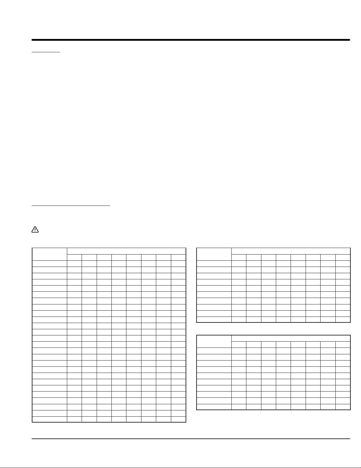
Appendix A
Reference Information
Glossary
BP Bypass Contactor
CC Current Calibrator
CCW Counterclockwise
CL Current Limit
CM Current Monitor
CS & RS Resistor & Capacitor series
circuit
CUR MON Current Monitor
CT Current Transformer
CW Clockwise
FLA Full Load Amperes (Motor)
LCM Logic Control Module
LED Light Emitting Diode
MCP Motor Circuit Protector
MOV Metal Oxide Varistor
MTR PWR Motor Power
OC Over Current Shutdown
OL Overload Relay
PC Power Cells
PF Power Factor Correction
PIV Peak Inverse Voltage
PT Starting Pulse Time
PWR Power
Ramp End End of Voltage Ramp
RD Ramp Down Time
RDD Ramp Down Disable
RMS Root Means Squared
RU Ramp Up Time
SCR Silicon Controlled Rectifier
Shunt Trip Shorted SCR Detection
SSC Soft Start Control
TACH Tachometer
TD Reduced torque value at start
of Ramp Down Time
TU Initial starting torque at Ramp
Up Time
X Control Transformer
Current Calibration Chart Settings for S1 are based on motors with 600% locked rotor amps. Motors with locked
rotor amps greater than 600% should use a higher setting. Baldor Super-ER motors on
high inertia loads should be set 1 or 2 settings higher than the suggested S1 setting. If a
load takes too long to start, use the next higher setting.
Caution: Select the table that matches you starter size only. Do not use the switch settings for a starter
size that is different than the one you are setting up. Using the wrong switch setting can damage
the Multipurpose Soft Starter control.
Size 008
Motor FLA
1.0−1.1 1 1 1 0 0 0 0 1
1.1−1.2 0 0 0 0 1 0 0 1
1.2−1.3 0 0 0 1 1 0 0 1
1.3−1.4 0 0 0 0 0 1 0 1
1.4−1.5 0 1 1 0 0 1 0 1
1.5−1.6 0 0 1 1 0 1 0 1
1.6−1.7 1 0 0 0 1 1 0 1
1.7−1.8 0 1 1 0 1 1 0 1
1.8−1.9 0 0 1 1 1 1 0 1
1.9−2.1 0 0 0 0 0 0 1 1
2.1−2.3 1 0 1 0 0 0 1 1
2.3−2.5 0 1 0 1 0 0 1 1
2.5−2.7 0 1 1 1 0 0 1 1
2.7−3.0 0 1 0 0 1 0 1 1
3.0−3.3 0 1 1 0 1 0 1 1
3.3−3.6 1 0 0 1 1 0 1 1
3.6−3.9 0 0 1 1 1 0 1 1
3.9−4.4 0 0 0 0 0 0 1 1
4.4−4.8 1 1 0 0 0 1 1 1
4.8−5.2 1 0 1 0 0 1 1 1
5.2−5.6 1 1 1 0 0 1 1 1
5.6−6.0 1 0 0 1 0 1 1 1
6.0−6.4 0 1 0 1 0 1 1 1
6.4−6.8 0 0 1 1 0 1 1 1
6.8−7.4 0 1 1 1 0 1 1 1
7.4−8.0 1 1 1 1 0 1 1 1
1 2 3 4 5 6 7 8
S1 Switch Position and Setting
Note: 0=Off, 1=On
Size 016
Motor FLA
6.0−6.5 1 0 0 0 0 1 1 1
6.5−7.0 0 0 1 0 0 1 1 1
7−8 1 1 1 0 0 1 1 1
8−9 1 0 0 1 0 1 1 1
9−10 1 1 0 1 0 1 1 1
10−11 1 0 1 1 0 1 1 1
11−12 1 1 1 1 0 1 1 1
12−13 0 0 0 0 1 1 1 1
13−14 0 1 0 0 1 1 1 1
14−16 1 1 0 0 1 1 1 1
Size 030
Motor FLA
12−13 1 0 0 0 0 1 1 1
13−14 1 1 0 0 0 1 1 1
14−15 1 0 1 0 0 1 1 1
15−16 1 1 1 0 0 1 1 1
16−18 1 0 0 1 0 1 1 1
18−20 1 1 0 1 0 1 1 1
20−22 1 0 1 1 0 1 1 1
22−24 0 1 1 1 0 1 1 1
24−27 0 0 0 0 1 1 1 1
27−30 0 1 0 0 1 1 1 1
1 2 3 4 5 6 7 8
1 2 3 4 5 6 7 8
S1 Switch Position and Setting
S1 Switch Position and Setting
Appendix A-1MN894
Page 60
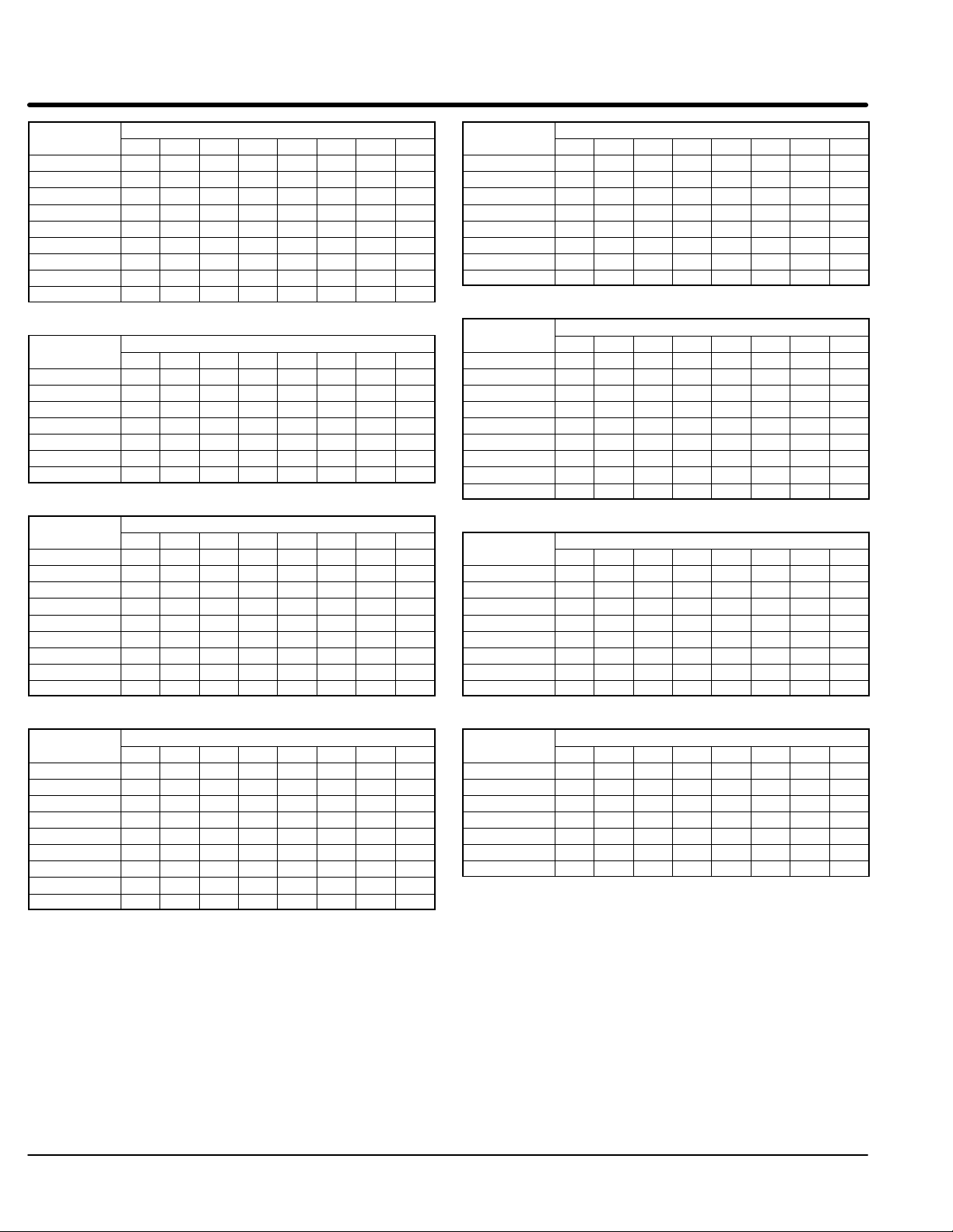
Size 055
Motor FLA
24−26 0 1 0 0 0 1 1 1
27−30 1 0 1 0 0 1 1 1
31−34 0 0 0 1 0 1 1 1
35−38 0 1 0 1 0 1 1 1
39−42 0 0 1 1 0 1 1 1
43−45 0 1 1 1 0 1 1 1
46−48 1 1 1 1 0 1 1 1
49−51 0 0 0 0 1 1 1 1
52−55 1 0 0 0 1 1 1 1
1 2 3 4 5 6 7 8
S1 Switch Position and Setting
Size 250
Motor FLA
108−11 3 1 1 0 0 1 0 1 0
114 −127 0 1 0 0 0 1 1 0
128−144 0 0 1 0 1 1 1 0
145−161 1 1 0 0 0 0 0 1
162−180 0 0 0 0 1 0 0 1
181−201 1 1 0 1 1 0 0 1
202−224 0 1 1 0 0 1 0 1
225−250 0 0 0 0 1 1 0 1
1 2 3 4 5 6 7 8
S1 Switch Position and Setting
Size 080
Motor FLA
44−46 0 1 1 1 0 1 1 1
47−52 0 0 0 0 1 1 1 1
53−58 1 0 0 0 1 1 1 1
59−64 1 1 0 0 1 1 1 1
65−69 0 0 1 0 1 1 1 1
70−75 1 0 1 0 1 1 1 1
76−80 0 1 1 0 1 1 1 1
Size 140
Motor FLA
58−63 0 1 0 0 0 1 1 0
64−70 1 0 0 0 1 1 1 0
71−78 1 1 1 1 1 1 1 0
79−86 0 0 1 1 0 0 0 1
87−95 0 1 1 0 1 0 0 1
96−105 0 0 0 0 0 1 0 1
106−120 1 1 0 1 0 1 0 1
121−128 1 0 0 0 1 1 0 1
129−140 0 0 0 1 1 1 0 1
Size 160
Motor FLA
65−70 1 0 0 0 1 1 1 0
71−78 1 1 1 1 1 1 1 0
79−87 0 0 1 1 0 0 0 1
88−97 1 1 1 0 1 0 0 1
98−108 0 1 0 0 0 1 0 1
109−120 1 1 0 1 0 1 0 1
121−135 0 0 1 0 1 1 0 1
136−148 1 1 0 1 1 1 0 1
149−160 1 0 0 0 0 0 1 1
1 2 3 4 5 6 7 8
1 2 3 4 5 6 7 8
1 2 3 4 5 6 7 8
S1 Switch Position and Setting
S1 Switch Position and Setting
S1 Switch Position and Setting
Note: 0=Off, 1=On
Size 420
Motor FLA
200−214 1 1 0 0 0 1 0 1
215−234 0 1 0 1 0 1 0 1
235−249 1 0 0 0 1 1 0 1
250−274 1 1 1 0 1 1 0 1
275−299 0 0 1 1 1 1 0 1
300−329 1 1 0 0 0 0 1 1
330−361 0 0 0 1 0 0 1 1
362−390 0 0 1 1 0 0 1 1
391−420 0 0 0 0 1 0 1 1
Size 600
Motor FLA
320−340 1 1 0 1 0 0 0 1
341−360 0 1 0 0 1 0 0 1
361−390 0 1 0 1 1 0 0 1
391−430 1 1 0 0 0 1 0 1
431−470 1 1 0 1 0 1 0 1
471−520 0 1 0 0 1 1 0 1
521−570 1 0 0 1 1 1 0 1
571−600 1 1 1 1 1 1 0 1
Size 840
Motor FLA
471−520 0 1 0 0 1 1 0 1
521−570 1 0 0 1 1 1 0 1
571−630 1 1 1 1 1 1 0 1
631−690 0 1 1 0 0 0 1 1
691−740 1 0 0 1 0 0 1 1
741−800 1 0 1 1 0 0 1 1
801−840 0 0 0 0 1 0 1 1
1 2 3 4 5 6 7 8
1 2 3 4 5 6 7 8
1 2 3 4 5 6 7 8
S1 Switch Position and Setting
S1 Switch Position and Setting
S1 Switch Position and Setting
A-2 Appendix MN894
Page 61
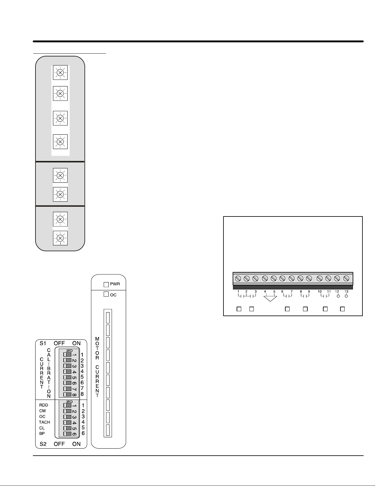
Quick Reference Chart
RU
+ −
TU
− +
CL
− +
PT
− +
RD
+ −
TD
− +
CM
− +
PF
− +
50 3
40 75
75 400
0 1.5
50 5
0 100
50 400
0 100
Ramp Up Time (3-50 sec.)
Tachometer: Time to reach full speed.
S
T
A
R
T
Voltage: Time to reach full speed.
Torque Up (40-75% voltage)
Tachometer: Disabled.
Voltage: Initial starting voltage for ramp.
Current Limit (75-400% FLA)
Tachometer or voltage: Enabled by S2-5=ON. Maximum current during ramp up and ramp down.
Pulse Time (0-1.5 sec.)
Tachometer: Disabled.
Voltage: Duration of 400% FLA starting pulse.
Ramp Down Time (5-50 sec.) − (Disabled with S2-1=ON)
Tachometer: Time to reach zero speed.
S
Voltage: Time to reach zero speed.
T
Torque Down Advance (0-100%) − (Disabled with S2-1=ON)
Tachometer or voltage: Percentage reduction from full motor voltage for starting ramp down to zero volts.
O
P
Current Monitor (50-400% FLA) Enabled at end of start cycle.
S2-2=ON: If motor current exceeds CM value, control will shutdown, CUR MON contact will close and
R
S2-2=OFF: Control will not shutdown, contact
U
Power Factor (0-100%)
N
CUR MON light is ON.
will close, LED is ON.
0 to maximum allowable motor voltage
reduction to improve power factor.
CUR MON: Indicates CM or CL have been exceeded.
MTR PWR: Indicates voltage is applied to motor
during start, run & ramp down.
TACH: Tachometer input (0-10VDC).
RAMP END: End of start ramp (full run condition).
SHUNT TRIP: Shunt trip due to shorted SCR.
START/RUN: Confirm Close to Run contact is closed.
CLOSE TO RUN: Start contact is closed.
Power applied to control.
Overcurrent shut down
(450% FLA)
CUR
MON
MTR
PWR
TACH
RAMP
END
SHUNT
TRIP
START/
RUN
CLOSE
TO RUN
S1 Current Calibration and “Motor Current” bar graph. S1 selects 255 calibration points for motor FLA.
See “Current Calibration Chart” in this section for the proper setting.
Bar Graph, displays the value of motor current during operation.
RDD: S2-1, Ramp Down Disable.
ON Control is immediately disabled when the “Close to Run” input is opened.
OFF Control will ramp down when the “Close to Run” input is opened.
CM: S2-2, Current Monitor Trip.
ON Control will disable and CUR MON light and contact will indicate an overcurrent condition.
OFF CUR MON light and contact will indicate an overcurrent condition.
OC: S2-3, Over current shut down.
ON Overcurrent shutdown will turn on CUR MON light and close the CUR MON contact.
OFF Overcurrent shutdown will disable control with no affect to CUR MON light and contact.
TACH: S2-4, Tachometer input enable.
ON Control is in tachometer feedback ramp mode.
OFF Control is in voltage ramp mode.
CL: S2-5, Current Limit enable.
ON Current will not exceed Current Limit adjustment during ramp up and down except during pulse start.
OFF Current Limit adjustment has no effect.
BP: S2-6, Bypass contactor enable.
ON Shunt trip circuit is disabled during full on condition for bypass contactor to be used.
OFF Shunt trip circuit is enabled in all conditions.
Appendix A-3MN894
Page 62
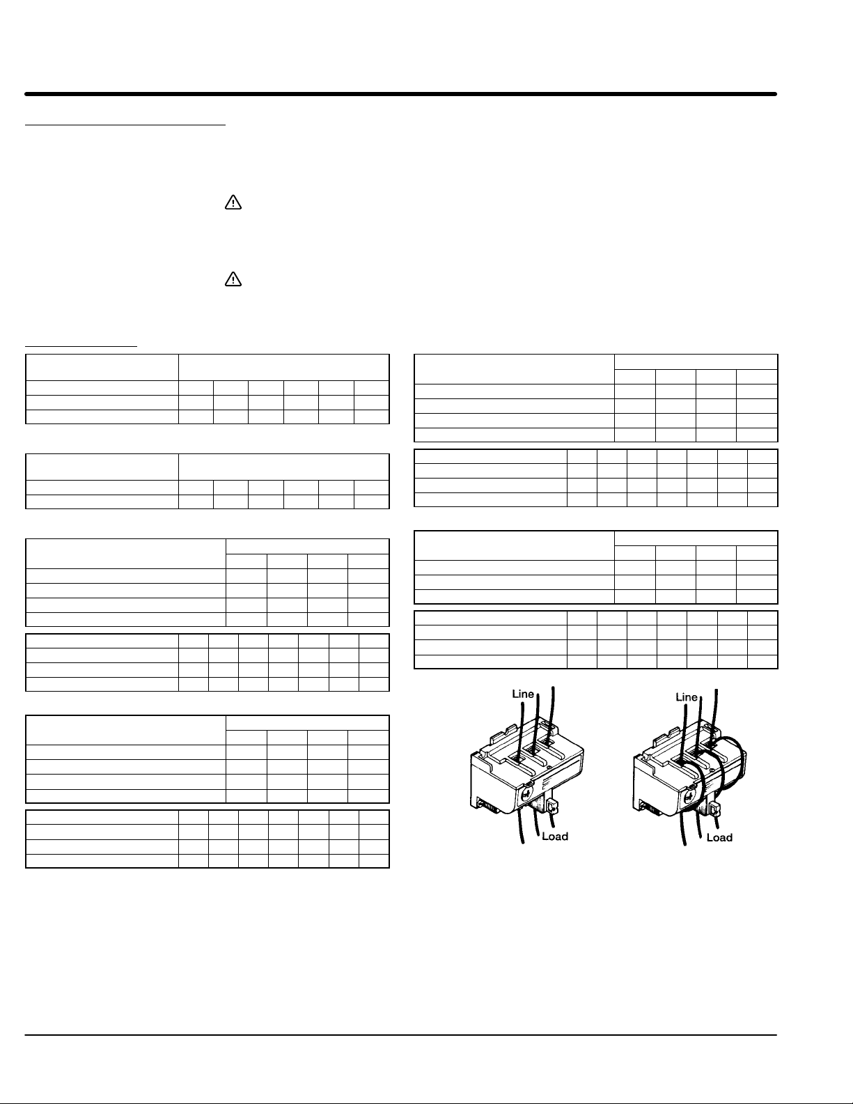
Overload Relay Adjustment
A class 30 electonic relay is provided with combination and non-combination starters.
Read the FLA from the motor nameplate and set the overload dial to the correct ampere
setting. Refer to the table that represents the starter size.
Caution: Select the table that matches you starter size only. Do not use the
Caution: For starters size 8, 16 and 30A is direct reading. Using the wrong
Overload Relay - Electronic Class 30
Size 055# Passes
through the window
1 (Straight through) 45 50 60 70 80 90
2 (1 loop) 22.5 25 30 35 40 45
3 (2 loop) 11 12.5 15 17.5 20 22.5
Size 080# Passes
through the window
1 (Straight Through) 45 50 60 70 80 90
2 (1 loop) 22.5 25 30 35 40 45
Dial Setting / Amps
Dial Setting / Amps
switch settings for a starter size that is different than the one you
are setting up. Using the wrong switch setting can damage the
Multipurpose Soft Starter control.
setting may damage the multiputpose soft start control.
# Passes through the window
Size 250
2 (1 loop) 150 200 250 −
3 (2 loop) 100 133 167 200
4 (3 loop) 75 100 125 150
5 (4 loop) 60 80 100 120
# Passes 9 10 11 12 14 16 18
5 (4 loops) 180 200 220 240 − − −
6 (5 loops) 166 185 203 216 − − −
7 (6 loops) 126 140 154 168 196 224 254
Dial Setting / Amps
3 4 5 6
# Passes through the window
# Passes through the window
Size 160
3 (2 loops) 100 133 167 −
4 (3 loops) 75 100 125 150
5 (4 loops) 60 80 100 120
6 (5 loops) 50 67 83 100
# Passes 9 10 11 12 14 16 18
6 (5 loops) 160 − − − − − −
7 (6 loops) 128 143 157 − − − −
8 (7 loops) 112 125 137 150 − − −
Size 420
1 (Straight Through) 300 400 500 −
2 (1 loop) 150 200 250 300
3 (2 loop) 100 133 167 200
4 (3 loop) 75 100 125 150
# Passes 9 10 11 12 14 16 18
3 (2 loops) 300 333 366 400 − − −
4 (3 loops) 225 250 275 300 350 400 −
5 (4 loops) 180 200 220 240 280 320 360
Dial Setting / Amps
3 4 5 6
Dial Setting / Amps
3 4 5 6
# Passes through the window
Size 840
1 (Straight Through) 600 800 1000 −
2 (1 loop) 300 400 500 600
3 (2 loop) 150 200 250 300
# Passes 9 10 11 12 14 16 18
3 (2 loops) 600 667 734 800 − − −
4 (3 loops) 450 500 550 600 700 800 −
5 (4 loops) 360 400 440 480 560 640 720
Dial Setting / Amps
3 4 5 6
1 Pass (Straight Through) 2 Pass (1 Loop)
A-4 Appendix MN894
Page 63

Appendix B
Circuit Breaker Adjustments
Circuit Breaker Adjustment (Inrush current estimation)
Mechanical adjustment of the trip setting may be necessary if the circuit breaker is
replaced. The first step of this adjustment procedure is to determine the motor inrush
current (in amperes). Inrush current is also called “Locked Rotor AMPS” or “LRA”.
In soft start applications, the initial voltage applied to the motor is reduced to
approximately 40% to 70% of nominal line voltage. It is necessary to set set the trip
current for the circuit breaker to the proper inrush current value. This inrush current is
determined by motor horsepower and motor design characteristics. To define inrush
characteristics, code letters are used. This code letter defines both the low voltage and
high voltage inrush values for dual voltage motors. Table B-1 shows these code letters.
(KVA = Kilovolt-Amperes; HP = Horsepower).
KVA/HP Calculation of motor
Table B-1 Code Letter Definition
Code Letter KVA/HP
Range
A 0.00 - 3.14 1.6
B 3.15 - 3.54 3.3
C 3.55 - 3.99 3.8
D 4.00 - 4.49 4.3
E 4.50 - 4.99 4.7
F 5.00 - 5.59 5.3
G 5.60 - 6.29 5.9
H 6.30 - 7.09 6.7
J 7.10 - 7.99 7.5
K 8.00 - 8.99 8.5
L 9.00 - 9.99 9.5
M 10.00 - 11.19 10.6
N 11.20 - 12.49 11.8
P 12.50 - 13.99 13.2
R 14.00 - 15.99 15.0
3 Phase Inrush Current Calculation (Use mid range value for KVA/HP)
Inrush AMPS +
ǒ
HP
KVA/HP
Mid-Range Value
KVA
mid range value
Ǔ
xHPx577
Rated Volts
Adjustments B-1MN894
Page 64

Section 1
General Information
Example: 3 phase Motor rated at 50 HP at 460VAC, 65 amps (continuous), code letter J.
7.5 x 50 x 577
I
Inrush
+
ǒ
460
Circuit Breaker AdjustmentThe calculated Inrush Amps value is used to initially set the breaker. If the circuit breaker
trips during use, the trip level is increased. Refer to Figure B-1.
Caution: The trip level of the circuit breaker must remain as low as possible
to avoid damage to equipment. If set too high, the circuit breaker
may not trip during a high overcurrent condition.
1. Refer to the manufacturers literature or the rating label on the circuit breaker.
Determine the correct setting of the Trip Level adjustment based on the
calculated Inrush Amps. Set the Trip Level adjustment to this initial level.
2. Turn on power and start the motor.
3. If the breaker trips and the shunt trip indicator on the LCM soft start control
module is OFF, the circuit breaker tripped for an overcurrent condition. Turn
power off and set the Trip Level to the next greater setting.
4. Turn on power and start the motor.
5. If the breaker trips, repeat steps 3 and 4. If the Trip Level adjustment is at the
maximum setting and you have verified there is no phase to phase or phase to
ground shorts, perform step 6. If the shunt trip causes the breaker to trip, refer
to Troubleshooting Section 5 of this manual.
6. If the breaker continues to trip due to inrush current (and not a short circuit) the
Rating Plug may be replaced with one that has a greater current rating. Refer
to the circuit breaker manufacturers information and ratings.
Ǔ
+ 470Amperes
Shunt Trip Wires to
LCM soft start module
Handle
Shunt Trip Device
Trip Level
Figure B-1 Magnetic Circuit Breaker
ON
Tripped
OFF
Reset
Manual Trip
Rating Plug
B-2 Adjustments MN894
Page 65

Baldor District Offices
Page 66

BALDOR ELECTRIC COMPANY
P.O. Box 2400
Ft. Smith, AR 72901−2400
(479) 646−4711
Fax (479) 648−5792
© Baldor Electric Company
MN894
Printed in USA
9/06
 Loading...