

Page 1

Series 29
Digital DC Control
Installation & Operating Manual
9/03 MN792
Page 2

Page 3

Table of Contents
Section 1
Quick Start 1-1. . . . . . . . . . . . . . . . . . . . . . . . . . . . . . . . . . . . . . . . . . . . . . . . . . . . . . . . . . . . . . . . . . . . . . . . . . . . . . . . . . . . . .
Minimum Connection Requirements 1-1. . . . . . . . . . . . . . . . . . . . . . . . . . . . . . . . . . . . . . . . . . . . . . . . . . . . . . . . . . . . .
Power and Motor Connections 1-1. . . . . . . . . . . . . . . . . . . . . . . . . . . . . . . . . . . . . . . . . . . . . . . . . . . . . . . . . . . . . .
Reference and Jumpers for Keypad Operation 1-1. . . . . . . . . . . . . . . . . . . . . . . . . . . . . . . . . . . . . . . . . . . . . . . .
Parameter Settings (for Keypad Operation) 1-1. . . . . . . . . . . . . . . . . . . . . . . . . . . . . . . . . . . . . . . . . . . . . . . . . .
Reference and Jumpers for Remote Operation 1-2. . . . . . . . . . . . . . . . . . . . . . . . . . . . . . . . . . . . . . . . . . . . . . . .
Speed Feedback 1-2. . . . . . . . . . . . . . . . . . . . . . . . . . . . . . . . . . . . . . . . . . . . . . . . . . . . . . . . . . . . . . . . . . . . . . . . . .
Serial Link 1-2. . . . . . . . . . . . . . . . . . . . . . . . . . . . . . . . . . . . . . . . . . . . . . . . . . . . . . . . . . . . . . . . . . . . . . . . . . . . . . .
Section 2
General Information 2-1. . . . . . . . . . . . . . . . . . . . . . . . . . . . . . . . . . . . . . . . . . . . . . . . . . . . . . . . . . . . . . . . . . . . . . . . . . . . . .
Overview 2-1. . . . . . . . . . . . . . . . . . . . . . . . . . . . . . . . . . . . . . . . . . . . . . . . . . . . . . . . . . . . . . . . . . . . . . . . . . . . . . . . . . . .
CE Compliance 2-1. . . . . . . . . . . . . . . . . . . . . . . . . . . . . . . . . . . . . . . . . . . . . . . . . . . . . . . . . . . . . . . . . . . . . . . . . . . . . . .
Enclosure Sizes 2-1. . . . . . . . . . . . . . . . . . . . . . . . . . . . . . . . . . . . . . . . . . . . . . . . . . . . . . . . . . . . . . . . . . . . . . . . . . . . . . .
Limited W arranty 2-1. . . . . . . . . . . . . . . . . . . . . . . . . . . . . . . . . . . . . . . . . . . . . . . . . . . . . . . . . . . . . . . . . . . . . . . . . . . . . .
Product Notice 2-2. . . . . . . . . . . . . . . . . . . . . . . . . . . . . . . . . . . . . . . . . . . . . . . . . . . . . . . . . . . . . . . . . . . . . . . . . . . . . . . .
Safety Notice 2-2. . . . . . . . . . . . . . . . . . . . . . . . . . . . . . . . . . . . . . . . . . . . . . . . . . . . . . . . . . . . . . . . . . . . . . . . . . . . . . . . .
Section 3
Getting Started 3-1. . . . . . . . . . . . . . . . . . . . . . . . . . . . . . . . . . . . . . . . . . . . . . . . . . . . . . . . . . . . . . . . . . . . . . . . . . . . . . . . . . .
Control Overview 3-1. . . . . . . . . . . . . . . . . . . . . . . . . . . . . . . . . . . . . . . . . . . . . . . . . . . . . . . . . . . . . . . . . . . . . . . . . . . . . .
Control Loops 3-1. . . . . . . . . . . . . . . . . . . . . . . . . . . . . . . . . . . . . . . . . . . . . . . . . . . . . . . . . . . . . . . . . . . . . . . . . . . .
Control and Communications 3-1. . . . . . . . . . . . . . . . . . . . . . . . . . . . . . . . . . . . . . . . . . . . . . . . . . . . . . . . . . . . . . .
Local and Remote Modes 3-2. . . . . . . . . . . . . . . . . . . . . . . . . . . . . . . . . . . . . . . . . . . . . . . . . . . . . . . . . . . . . . . . . .
Source / Destination Tags 3-3. . . . . . . . . . . . . . . . . . . . . . . . . . . . . . . . . . . . . . . . . . . . . . . . . . . . . . . . . . . . . . . . . . . . . .
Programming Block 3-4. . . . . . . . . . . . . . . . . . . . . . . . . . . . . . . . . . . . . . . . . . . . . . . . . . . . . . . . . . . . . . . . . . . . . . . . . . . .
Section 4
Receiving and Installation 4-1. . . . . . . . . . . . . . . . . . . . . . . . . . . . . . . . . . . . . . . . . . . . . . . . . . . . . . . . . . . . . . . . . . . . . . . . . . .
Receiving & Inspection 4-1. . . . . . . . . . . . . . . . . . . . . . . . . . . . . . . . . . . . . . . . . . . . . . . . . . . . . . . . . . . . . . . . . . . . . . . . .
Location Considerations 4-1. . . . . . . . . . . . . . . . . . . . . . . . . . . . . . . . . . . . . . . . . . . . . . . . . . . . . . . . . . . . . . . . . . . . . . . .
Cover Removal 4-2. . . . . . . . . . . . . . . . . . . . . . . . . . . . . . . . . . . . . . . . . . . . . . . . . . . . . . . . . . . . . . . . . . . . . . . . . . . . . . .
Mechanical Installation 4-3. . . . . . . . . . . . . . . . . . . . . . . . . . . . . . . . . . . . . . . . . . . . . . . . . . . . . . . . . . . . . . . . . . . . . . . . .
External Vent Kit 4-3. . . . . . . . . . . . . . . . . . . . . . . . . . . . . . . . . . . . . . . . . . . . . . . . . . . . . . . . . . . . . . . . . . . . . . . . . .
Optional Remote Keypad Installation 4-4. . . . . . . . . . . . . . . . . . . . . . . . . . . . . . . . . . . . . . . . . . . . . . . . . . . . . . . .
Electrical Installation 4-5. . . . . . . . . . . . . . . . . . . . . . . . . . . . . . . . . . . . . . . . . . . . . . . . . . . . . . . . . . . . . . . . . . . . . . . . . . .
System Grounding 4-5. . . . . . . . . . . . . . . . . . . . . . . . . . . . . . . . . . . . . . . . . . . . . . . . . . . . . . . . . . . . . . . . . . . . . . . .
Line Impedance 4-5. . . . . . . . . . . . . . . . . . . . . . . . . . . . . . . . . . . . . . . . . . . . . . . . . . . . . . . . . . . . . . . . . . . . . . . . . .
Power Disconnect 4-5. . . . . . . . . . . . . . . . . . . . . . . . . . . . . . . . . . . . . . . . . . . . . . . . . . . . . . . . . . . . . . . . . . . . . . . . .
Protection Devices 4-5. . . . . . . . . . . . . . . . . . . . . . . . . . . . . . . . . . . . . . . . . . . . . . . . . . . . . . . . . . . . . . . . . . . . . . . .
Isolation Transformer Sizing 4-6. . . . . . . . . . . . . . . . . . . . . . . . . . . . . . . . . . . . . . . . . . . . . . . . . . . . . . . . . . . . . . . .
Single Phase Power 4-6. . . . . . . . . . . . . . . . . . . . . . . . . . . . . . . . . . . . . . . . . . . . . . . . . . . . . . . . . . . . . . . . . . . . . . .
Power Connections 4-8. . . . . . . . . . . . . . . . . . . . . . . . . . . . . . . . . . . . . . . . . . . . . . . . . . . . . . . . . . . . . . . . . . . . . . .
Logic Power 4-8. . . . . . . . . . . . . . . . . . . . . . . . . . . . . . . . . . . . . . . . . . . . . . . . . . . . . . . . . . . . . . . . . . . . . . . . . . . . .
Motor Connections 4-9. . . . . . . . . . . . . . . . . . . . . . . . . . . . . . . . . . . . . . . . . . . . . . . . . . . . . . . . . . . . . . . . . . . . . . . .
M-Contactor 4-11. . . . . . . . . . . . . . . . . . . . . . . . . . . . . . . . . . . . . . . . . . . . . . . . . . . . . . . . . . . . . . . . . . . . . . . . . . . . . .
Table of Contents iMN792
Page 4

Blower Motor Starter 4-12. . . . . . . . . . . . . . . . . . . . . . . . . . . . . . . . . . . . . . . . . . . . . . . . . . . . . . . . . . . . . . . . . . . . . .
Thermal Protection 4-13. . . . . . . . . . . . . . . . . . . . . . . . . . . . . . . . . . . . . . . . . . . . . . . . . . . . . . . . . . . . . . . . . . . . . . . .
Encoder Installation 4-13. . . . . . . . . . . . . . . . . . . . . . . . . . . . . . . . . . . . . . . . . . . . . . . . . . . . . . . . . . . . . . . . . . . . . . .
Tachometer Installation 4-14. . . . . . . . . . . . . . . . . . . . . . . . . . . . . . . . . . . . . . . . . . . . . . . . . . . . . . . . . . . . . . . . . . . .
Control I/O Signal Connections 4-15. . . . . . . . . . . . . . . . . . . . . . . . . . . . . . . . . . . . . . . . . . . . . . . . . . . . . . . . . . . . . . . . . .
Analog Inputs 4-15. . . . . . . . . . . . . . . . . . . . . . . . . . . . . . . . . . . . . . . . . . . . . . . . . . . . . . . . . . . . . . . . . . . . . . . . . . . .
Analog Outputs 4-16. . . . . . . . . . . . . . . . . . . . . . . . . . . . . . . . . . . . . . . . . . . . . . . . . . . . . . . . . . . . . . . . . . . . . . . . . . .
Digital Inputs 4-16. . . . . . . . . . . . . . . . . . . . . . . . . . . . . . . . . . . . . . . . . . . . . . . . . . . . . . . . . . . . . . . . . . . . . . . . . . . . .
Digital Outputs 4-17. . . . . . . . . . . . . . . . . . . . . . . . . . . . . . . . . . . . . . . . . . . . . . . . . . . . . . . . . . . . . . . . . . . . . . . . . . . .
RS232 Connections 4-18. . . . . . . . . . . . . . . . . . . . . . . . . . . . . . . . . . . . . . . . . . . . . . . . . . . . . . . . . . . . . . . . . . . . . . . . . . .
System Port (P3) Configuration 4-18. . . . . . . . . . . . . . . . . . . . . . . . . . . . . . . . . . . . . . . . . . . . . . . . . . . . . . . . . . . . . . . . .
Section 5
Switch Setting and Start-Up 5-1. . . . . . . . . . . . . . . . . . . . . . . . . . . . . . . . . . . . . . . . . . . . . . . . . . . . . . . . . . . . . . . . . . . . . . .
Pre–Operation Checks 5-1. . . . . . . . . . . . . . . . . . . . . . . . . . . . . . . . . . . . . . . . . . . . . . . . . . . . . . . . . . . . . . . . . . . . . . . . .
Power up in Local Mode with Armature Feedback 5-1. . . . . . . . . . . . . . . . . . . . . . . . . . . . . . . . . . . . . . . . . . . . . . . . . .
Power up in Remote Mode with Feedback 5-5. . . . . . . . . . . . . . . . . . . . . . . . . . . . . . . . . . . . . . . . . . . . . . . . . . . . . . . .
Autotune 5-12. . . . . . . . . . . . . . . . . . . . . . . . . . . . . . . . . . . . . . . . . . . . . . . . . . . . . . . . . . . . . . . . . . . . . . . . . . . . . . . . . . . . .
Speed Loop Adjustment 5-13. . . . . . . . . . . . . . . . . . . . . . . . . . . . . . . . . . . . . . . . . . . . . . . . . . . . . . . . . . . . . . . . . . . . . . . .
Starting and Stopping Methods 5-13. . . . . . . . . . . . . . . . . . . . . . . . . . . . . . . . . . . . . . . . . . . . . . . . . . . . . . . . . . . . . . . . . .
Upload/Download Procedure 5-17. . . . . . . . . . . . . . . . . . . . . . . . . . . . . . . . . . . . . . . . . . . . . . . . . . . . . . . . . . . . . . . . . . . .
DUMP Procedure 5-18. . . . . . . . . . . . . . . . . . . . . . . . . . . . . . . . . . . . . . . . . . . . . . . . . . . . . . . . . . . . . . . . . . . . . . . . . . . . .
Section 6
Programming 6-1. . . . . . . . . . . . . . . . . . . . . . . . . . . . . . . . . . . . . . . . . . . . . . . . . . . . . . . . . . . . . . . . . . . . . . . . . . . . . . . . . . . .
Overview 6-1. . . . . . . . . . . . . . . . . . . . . . . . . . . . . . . . . . . . . . . . . . . . . . . . . . . . . . . . . . . . . . . . . . . . . . . . . . . . . . . . . . . .
Menu System 6-1. . . . . . . . . . . . . . . . . . . . . . . . . . . . . . . . . . . . . . . . . . . . . . . . . . . . . . . . . . . . . . . . . . . . . . . . . . . . . . . . .
Parameter Descriptions 6-4. . . . . . . . . . . . . . . . . . . . . . . . . . . . . . . . . . . . . . . . . . . . . . . . . . . . . . . . . . . . . . . . . . . . . . . .
Analog Inputs 6-4. . . . . . . . . . . . . . . . . . . . . . . . . . . . . . . . . . . . . . . . . . . . . . . . . . . . . . . . . . . . . . . . . . . . . . . . . . . .
Analog Outputs 6-6. . . . . . . . . . . . . . . . . . . . . . . . . . . . . . . . . . . . . . . . . . . . . . . . . . . . . . . . . . . . . . . . . . . . . . . . . . .
AUX I/O 6-8. . . . . . . . . . . . . . . . . . . . . . . . . . . . . . . . . . . . . . . . . . . . . . . . . . . . . . . . . . . . . . . . . . . . . . . . . . . . . . . . .
Block Diagram 6-11. . . . . . . . . . . . . . . . . . . . . . . . . . . . . . . . . . . . . . . . . . . . . . . . . . . . . . . . . . . . . . . . . . . . . . . . . . . .
Calibration 6-12. . . . . . . . . . . . . . . . . . . . . . . . . . . . . . . . . . . . . . . . . . . . . . . . . . . . . . . . . . . . . . . . . . . . . . . . . . . . . . .
Configure Drive 6-14. . . . . . . . . . . . . . . . . . . . . . . . . . . . . . . . . . . . . . . . . . . . . . . . . . . . . . . . . . . . . . . . . . . . . . . . . . .
Current Loop 6-15. . . . . . . . . . . . . . . . . . . . . . . . . . . . . . . . . . . . . . . . . . . . . . . . . . . . . . . . . . . . . . . . . . . . . . . . . . . . .
Current Profile 6-17. . . . . . . . . . . . . . . . . . . . . . . . . . . . . . . . . . . . . . . . . . . . . . . . . . . . . . . . . . . . . . . . . . . . . . . . . . . .
Diagnostics 6-18. . . . . . . . . . . . . . . . . . . . . . . . . . . . . . . . . . . . . . . . . . . . . . . . . . . . . . . . . . . . . . . . . . . . . . . . . . . . . .
Digital Inputs 6-21. . . . . . . . . . . . . . . . . . . . . . . . . . . . . . . . . . . . . . . . . . . . . . . . . . . . . . . . . . . . . . . . . . . . . . . . . . . . .
Digital Outputs 6-25. . . . . . . . . . . . . . . . . . . . . . . . . . . . . . . . . . . . . . . . . . . . . . . . . . . . . . . . . . . . . . . . . . . . . . . . . . . .
Field Control 6-26. . . . . . . . . . . . . . . . . . . . . . . . . . . . . . . . . . . . . . . . . . . . . . . . . . . . . . . . . . . . . . . . . . . . . . . . . . . . .
Alarms 6-28. . . . . . . . . . . . . . . . . . . . . . . . . . . . . . . . . . . . . . . . . . . . . . . . . . . . . . . . . . . . . . . . . . . . . . . . . . . . . . . . . .
Jog/Slack 6-29. . . . . . . . . . . . . . . . . . . . . . . . . . . . . . . . . . . . . . . . . . . . . . . . . . . . . . . . . . . . . . . . . . . . . . . . . . . . . . . .
Menus 6-30. . . . . . . . . . . . . . . . . . . . . . . . . . . . . . . . . . . . . . . . . . . . . . . . . . . . . . . . . . . . . . . . . . . . . . . . . . . . . . . . . . .
OP Station 6-31. . . . . . . . . . . . . . . . . . . . . . . . . . . . . . . . . . . . . . . . . . . . . . . . . . . . . . . . . . . . . . . . . . . . . . . . . . . . . . .
ii Table of Contents MN792
Page 5

Password 6-31. . . . . . . . . . . . . . . . . . . . . . . . . . . . . . . . . . . . . . . . . . . . . . . . . . . . . . . . . . . . . . . . . . . . . . . . . . . . . . . .
PID 6-32. . . . . . . . . . . . . . . . . . . . . . . . . . . . . . . . . . . . . . . . . . . . . . . . . . . . . . . . . . . . . . . . . . . . . . . . . . . . . . . . . . . . .
Raise/Lower 6-34. . . . . . . . . . . . . . . . . . . . . . . . . . . . . . . . . . . . . . . . . . . . . . . . . . . . . . . . . . . . . . . . . . . . . . . . . . . . .
Ramps 6-35. . . . . . . . . . . . . . . . . . . . . . . . . . . . . . . . . . . . . . . . . . . . . . . . . . . . . . . . . . . . . . . . . . . . . . . . . . . . . . . . . .
Setpoint Sum 1 6-38. . . . . . . . . . . . . . . . . . . . . . . . . . . . . . . . . . . . . . . . . . . . . . . . . . . . . . . . . . . . . . . . . . . . . . . . . . .
Speed Loop 6-39. . . . . . . . . . . . . . . . . . . . . . . . . . . . . . . . . . . . . . . . . . . . . . . . . . . . . . . . . . . . . . . . . . . . . . . . . . . . . .
Advanced 6-41. . . . . . . . . . . . . . . . . . . . . . . . . . . . . . . . . . . . . . . . . . . . . . . . . . . . . . . . . . . . . . . . . . . . . . . . . . . . . . . .
Standstill 6-42. . . . . . . . . . . . . . . . . . . . . . . . . . . . . . . . . . . . . . . . . . . . . . . . . . . . . . . . . . . . . . . . . . . . . . . . . . . . . . . .
Stop Rates 6-43. . . . . . . . . . . . . . . . . . . . . . . . . . . . . . . . . . . . . . . . . . . . . . . . . . . . . . . . . . . . . . . . . . . . . . . . . . . . . . .
System Port P3 6-48. . . . . . . . . . . . . . . . . . . . . . . . . . . . . . . . . . . . . . . . . . . . . . . . . . . . . . . . . . . . . . . . . . . . . . . . . . .
5703 Support 6-51. . . . . . . . . . . . . . . . . . . . . . . . . . . . . . . . . . . . . . . . . . . . . . . . . . . . . . . . . . . . . . . . . . . . . . . . . . . . .
TEC Option 6-52. . . . . . . . . . . . . . . . . . . . . . . . . . . . . . . . . . . . . . . . . . . . . . . . . . . . . . . . . . . . . . . . . . . . . . . . . . . . . .
Section 7
Keypad Operation 7-1. . . . . . . . . . . . . . . . . . . . . . . . . . . . . . . . . . . . . . . . . . . . . . . . . . . . . . . . . . . . . . . . . . . . . . . . . . . . . . . .
Keypad 7-1. . . . . . . . . . . . . . . . . . . . . . . . . . . . . . . . . . . . . . . . . . . . . . . . . . . . . . . . . . . . . . . . . . . . . . . . . . . . . . . . . . . . . .
Keypad LED Status 7-2. . . . . . . . . . . . . . . . . . . . . . . . . . . . . . . . . . . . . . . . . . . . . . . . . . . . . . . . . . . . . . . . . . . . . . . . . . . .
Alarm Messages 7-2. . . . . . . . . . . . . . . . . . . . . . . . . . . . . . . . . . . . . . . . . . . . . . . . . . . . . . . . . . . . . . . . . . . . . . . . . . . . . .
Local Menu 7-3. . . . . . . . . . . . . . . . . . . . . . . . . . . . . . . . . . . . . . . . . . . . . . . . . . . . . . . . . . . . . . . . . . . . . . . . . . . . . . . . . . .
L/R Key 7-3. . . . . . . . . . . . . . . . . . . . . . . . . . . . . . . . . . . . . . . . . . . . . . . . . . . . . . . . . . . . . . . . . . . . . . . . . . . . . . . . . . . . .
PROG Key 7-3. . . . . . . . . . . . . . . . . . . . . . . . . . . . . . . . . . . . . . . . . . . . . . . . . . . . . . . . . . . . . . . . . . . . . . . . . . . . . . . . . . .
Menu System 7-4. . . . . . . . . . . . . . . . . . . . . . . . . . . . . . . . . . . . . . . . . . . . . . . . . . . . . . . . . . . . . . . . . . . . . . . . . . . . . . . . .
Menu Shortcuts and Special Key Combinations 7-6. . . . . . . . . . . . . . . . . . . . . . . . . . . . . . . . . . . . . . . . . . . . . . . . . . . .
Quick Tag Information 7-6. . . . . . . . . . . . . . . . . . . . . . . . . . . . . . . . . . . . . . . . . . . . . . . . . . . . . . . . . . . . . . . . . . . . .
Restore Factory Settings 7-6. . . . . . . . . . . . . . . . . . . . . . . . . . . . . . . . . . . . . . . . . . . . . . . . . . . . . . . . . . . . . . . . . . .
3 button reset 7-7. . . . . . . . . . . . . . . . . . . . . . . . . . . . . . . . . . . . . . . . . . . . . . . . . . . . . . . . . . . . . . . . . . . . . . . . . . . .
Operation Examples 7-8. . . . . . . . . . . . . . . . . . . . . . . . . . . . . . . . . . . . . . . . . . . . . . . . . . . . . . . . . . . . . . . . . . . . . . . . . . .
Select a Menu View Level 7-8. . . . . . . . . . . . . . . . . . . . . . . . . . . . . . . . . . . . . . . . . . . . . . . . . . . . . . . . . . . . . . . . . .
Language Selection 7-8. . . . . . . . . . . . . . . . . . . . . . . . . . . . . . . . . . . . . . . . . . . . . . . . . . . . . . . . . . . . . . . . . . . . . . .
Password Protection 7-9. . . . . . . . . . . . . . . . . . . . . . . . . . . . . . . . . . . . . . . . . . . . . . . . . . . . . . . . . . . . . . . . . . . . . .
Deactivate a Password 7-10. . . . . . . . . . . . . . . . . . . . . . . . . . . . . . . . . . . . . . . . . . . . . . . . . . . . . . . . . . . . . . . . . . . .
Save Settings 7-11. . . . . . . . . . . . . . . . . . . . . . . . . . . . . . . . . . . . . . . . . . . . . . . . . . . . . . . . . . . . . . . . . . . . . . . . . . . .
Section 8
Troubleshooting 8-1. . . . . . . . . . . . . . . . . . . . . . . . . . . . . . . . . . . . . . . . . . . . . . . . . . . . . . . . . . . . . . . . . . . . . . . . . . . . . . . . .
Reset a Trip Condition 8-1. . . . . . . . . . . . . . . . . . . . . . . . . . . . . . . . . . . . . . . . . . . . . . . . . . . . . . . . . . . . . . . . . . . . . . . . .
Fault Conditions 8-1. . . . . . . . . . . . . . . . . . . . . . . . . . . . . . . . . . . . . . . . . . . . . . . . . . . . . . . . . . . . . . . . . . . . . . . . . . . . . .
Serial (P3) Errors 8-1. . . . . . . . . . . . . . . . . . . . . . . . . . . . . . . . . . . . . . . . . . . . . . . . . . . . . . . . . . . . . . . . . . . . . . . . . . . . .
Alarm Messages 8-2. . . . . . . . . . . . . . . . . . . . . . . . . . . . . . . . . . . . . . . . . . . . . . . . . . . . . . . . . . . . . . . . . . . . . . . . . . . . . .
Last Alarm 8-2. . . . . . . . . . . . . . . . . . . . . . . . . . . . . . . . . . . . . . . . . . . . . . . . . . . . . . . . . . . . . . . . . . . . . . . . . . . . . . .
Health Word 8-2. . . . . . . . . . . . . . . . . . . . . . . . . . . . . . . . . . . . . . . . . . . . . . . . . . . . . . . . . . . . . . . . . . . . . . . . . . . . . .
Health Store 8-2. . . . . . . . . . . . . . . . . . . . . . . . . . . . . . . . . . . . . . . . . . . . . . . . . . . . . . . . . . . . . . . . . . . . . . . . . . . . .
Power Board LED Trip Information (Frame 4 and 5) 8-3. . . . . . . . . . . . . . . . . . . . . . . . . . . . . . . . . . . . . . . . . . . . . . . .
Table of Contents iiiMN792
Page 6

Manage Trips from the Keypad 8-4. . . . . . . . . . . . . . . . . . . . . . . . . . . . . . . . . . . . . . . . . . . . . . . . . . . . . . . . . . . . . . . . . .
Trip Messages 8-4. . . . . . . . . . . . . . . . . . . . . . . . . . . . . . . . . . . . . . . . . . . . . . . . . . . . . . . . . . . . . . . . . . . . . . . . . . . .
Symbolic Alarm Messages 8-5. . . . . . . . . . . . . . . . . . . . . . . . . . . . . . . . . . . . . . . . . . . . . . . . . . . . . . . . . . . . . . . . .
Self Test Alarms 8-6. . . . . . . . . . . . . . . . . . . . . . . . . . . . . . . . . . . . . . . . . . . . . . . . . . . . . . . . . . . . . . . . . . . . . . . . . .
Setting Trip Conditions 8-6. . . . . . . . . . . . . . . . . . . . . . . . . . . . . . . . . . . . . . . . . . . . . . . . . . . . . . . . . . . . . . . . . . . . .
Viewing Trip Conditions 8-6. . . . . . . . . . . . . . . . . . . . . . . . . . . . . . . . . . . . . . . . . . . . . . . . . . . . . . . . . . . . . . . . . . . .
Inhibiting Alarms 8-6. . . . . . . . . . . . . . . . . . . . . . . . . . . . . . . . . . . . . . . . . . . . . . . . . . . . . . . . . . . . . . . . . . . . . . . . . .
Test Points 8-7. . . . . . . . . . . . . . . . . . . . . . . . . . . . . . . . . . . . . . . . . . . . . . . . . . . . . . . . . . . . . . . . . . . . . . . . . . . . . . . . . . .
Maintenance 8-7. . . . . . . . . . . . . . . . . . . . . . . . . . . . . . . . . . . . . . . . . . . . . . . . . . . . . . . . . . . . . . . . . . . . . . . . . . . . . . . . .
Repair 8-7. . . . . . . . . . . . . . . . . . . . . . . . . . . . . . . . . . . . . . . . . . . . . . . . . . . . . . . . . . . . . . . . . . . . . . . . . . . . . . . . . . . . . . .
Section 9
Specifications & Product Data 9-1. . . . . . . . . . . . . . . . . . . . . . . . . . . . . . . . . . . . . . . . . . . . . . . . . . . . . . . . . . . . . . . . . . . . .
Specifications 9-1. . . . . . . . . . . . . . . . . . . . . . . . . . . . . . . . . . . . . . . . . . . . . . . . . . . . . . . . . . . . . . . . . . . . . . . . . . . . . . . . .
Keypad Display 9-2. . . . . . . . . . . . . . . . . . . . . . . . . . . . . . . . . . . . . . . . . . . . . . . . . . . . . . . . . . . . . . . . . . . . . . . . . . .
Control Specifications 9-2. . . . . . . . . . . . . . . . . . . . . . . . . . . . . . . . . . . . . . . . . . . . . . . . . . . . . . . . . . . . . . . . . . . . .
Encoder 9-3. . . . . . . . . . . . . . . . . . . . . . . . . . . . . . . . . . . . . . . . . . . . . . . . . . . . . . . . . . . . . . . . . . . . . . . . . . . . . . . . . . . . .
Tachometer 9-3. . . . . . . . . . . . . . . . . . . . . . . . . . . . . . . . . . . . . . . . . . . . . . . . . . . . . . . . . . . . . . . . . . . . . . . . . . . . . . . . . .
Terminal Tightening Torque 9-3. . . . . . . . . . . . . . . . . . . . . . . . . . . . . . . . . . . . . . . . . . . . . . . . . . . . . . . . . . . . . . . . . . . . .
Ratings 9-3. . . . . . . . . . . . . . . . . . . . . . . . . . . . . . . . . . . . . . . . . . . . . . . . . . . . . . . . . . . . . . . . . . . . . . . . . . . . . . . . . . . . . .
Dimensions 9-4. . . . . . . . . . . . . . . . . . . . . . . . . . . . . . . . . . . . . . . . . . . . . . . . . . . . . . . . . . . . . . . . . . . . . . . . . . . . . . . . . .
EMC Filters 9-5. . . . . . . . . . . . . . . . . . . . . . . . . . . . . . . . . . . . . . . . . . . . . . . . . . . . . . . . . . . . . . . . . . . . . . . . . . . . . . . . . .
Appendix A
CE Guidelines A-1. . . . . . . . . . . . . . . . . . . . . . . . . . . . . . . . . . . . . . . . . . . . . . . . . . . . . . . . . . . . . . . . . . . . . . . . . . . . . . . . . . . .
CE Declaration of Conformity A-1. . . . . . . . . . . . . . . . . . . . . . . . . . . . . . . . . . . . . . . . . . . . . . . . . . . . . . . . . . . . . . . . . . .
EMC – Conformity and CE – Marking A-1. . . . . . . . . . . . . . . . . . . . . . . . . . . . . . . . . . . . . . . . . . . . . . . . . . . . . . . . . . . .
EMC Installation Instructions A-3. . . . . . . . . . . . . . . . . . . . . . . . . . . . . . . . . . . . . . . . . . . . . . . . . . . . . . . . . . . . . . . . . . .
Appendix B
Parameter Table B-1. . . . . . . . . . . . . . . . . . . . . . . . . . . . . . . . . . . . . . . . . . . . . . . . . . . . . . . . . . . . . . . . . . . . . . . . . . . . . . . . . .
Parameter Values B-1. . . . . . . . . . . . . . . . . . . . . . . . . . . . . . . . . . . . . . . . . . . . . . . . . . . . . . . . . . . . . . . . . . . . . . . . . . . . .
Parameters Listed by Tag Number B-1. . . . . . . . . . . . . . . . . . . . . . . . . . . . . . . . . . . . . . . . . . . . . . . . . . . . . . . . . .
Parameters Listed by Name B-10. . . . . . . . . . . . . . . . . . . . . . . . . . . . . . . . . . . . . . . . . . . . . . . . . . . . . . . . . . . . . . . .
Parameters Listed by Keypad Menu B-19. . . . . . . . . . . . . . . . . . . . . . . . . . . . . . . . . . . . . . . . . . . . . . . . . . . . . . . . .
Parameters Listed by WB Block B-28. . . . . . . . . . . . . . . . . . . . . . . . . . . . . . . . . . . . . . . . . . . . . . . . . . . . . . . . . . . . .
Appendix C
Block Diagram C-1. . . . . . . . . . . . . . . . . . . . . . . . . . . . . . . . . . . . . . . . . . . . . . . . . . . . . . . . . . . . . . . . . . . . . . . . . . . . . . . . . . .
iv Table of Contents MN792
Page 7
Section 1
Quick Start
The basic steps for connection and setup are provided in this section. Detailed descriptions of each step and
parameter settings are provided later in this manual. Be sure to comply with all applicable codes when installing
this control. The Series 29 DC control is a one way control. That is, it is non–regen and cannot reverse
direction. It operates in the forward direction only. All references to reverse operation or regen operation apply
to the Series 30 DC Control only.
Minimum Connection Requirements Refer to Section 4 for cover removal procedure.
Power and Motor Connections
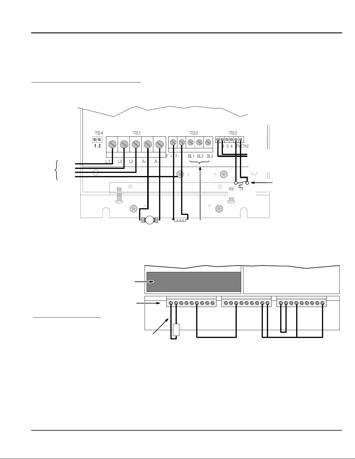
Figure 1-1 shows the minimum connections required at the power connector.
Figure 1-1 Power Connections
3 Phase
Power
L1
L2
L3
GND
Thermistor
For Size 1 & 2 controls, be sure the
logic power jumper is in the correct
position. Refer to Figure 4-9.
To 1 Phase 115VAC Control Power
(except units with internal
control transformer,
100hp and less)
or jumper TH1 to TH2 if
motor thermistor is not connected.
Armature
Reference and Jumpers for Keypad Operation
For keypad operation, the speed reference connections are not required. Speed is set at the keypad. Figure
1-2 shows the minimum connections required A, B and C signal connectors for Keypad operation.
Figure 1-2 Reference and Jumper Connections
If Optional Speed Feedback Board is used, refer
to Speed Feedback at the end of this section.
Signal Connections
Minimum jumper connections:
A1 to A2 – 500 ohm jumper for 20mA input
A6 to B3 – Analog Input 5 = +10VDC
B8 to C9 – PROG Stop = +24VDC
B9 to C9 – Coast Stop = +24VDC
C4 to C9 – Enable = +24VDC
C1 to C2 – No External Trip
Parameter Settings (for Keypad Operation)
The factory settings should be sufficient to operate the control using the “Local” mode with the keypad. Only a
few changes to the motor data parameters must be made. Before any parameters can be changed, set
System::Configure I/O::Configure Enable to enable. All LEDs will blink during configuration.
Note: To separate the various menu level designation, a double colon is used (System::Configure I/O).
500 ohm
Jumper for
0-20mA
Field
AB
0V 1
AnIn 1 2
500
Motor Starter on Size 1 & 2 controls.
AnIn 2 3
AnIn 3 4
AnIn 4 5
AnIn 5 6
AnOut 1 7
AnOut 2 8
0V 1
Not Used 2
Arm I Fbk 9
+10V Ref 3
DigOut 1 5
DigOut 2 6
DigOut 3 7
-10V Ref 4
Prog Stop 8
Coast Stop 9
Motor Blower connections when using optional
C
0V 1
Start 3
DigIn E 4
DigIn R 5
Ext Trip 2
+24V 9
DigIn 1 6
DigIn 2 7
DigIn 3 8
Quick Start 1-1MN792
Page 8
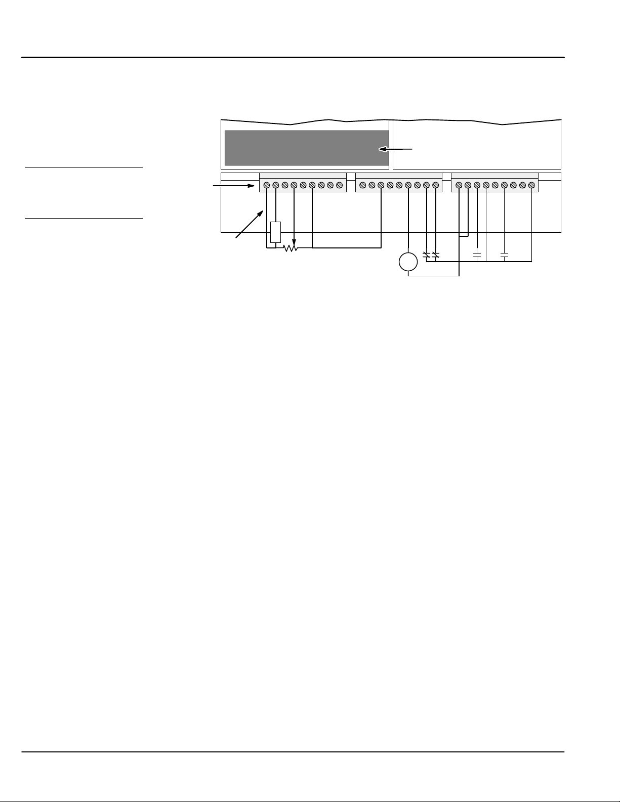
Reference and Jumpers for Remote Operation
For remote operation, the speed reference and other connections are made at the terminal strip connector. Not
all of these connections are shown in Figure 1-3.
Figure 1-3 Reference and Jumper Connections
Speed Reference connections:
A1 – one end of Pot
B3 – one end of Pot
A4 – wiper of Pot
C1 to C2 – No External Trip
Minimum jumper connections:
A1 to A2 – 500 ohm jumper for 20mA input
A6 to B3 – Analog Input 5 = +10VDC
C4 to C9 – Enable = +24VDC
C1 to C2 – No External Trip
Jumper if contacts are not used:
B8 to C9 – PROG Stop = +24VDC
B9 to C9 – Coast Stop = +24VDC
The Health relay (24VDC coil) may be installed between B6 and C1
to provide fault indication to an external device or circuit.
Signal
Connections
AB
500 ohm
Jumper for
0-20mA
Optional Speed
Feedback Board
0V 1
AnIn 1 2
AnIn 2 3
AnIn 3 4
AnIn 4 5
AnIn 5 6
AnOut 1 7
AnOut 2 8
500
0V 1
DigOut 1 5
Arm I Fbk 9
Not Used 2
DigOut 2 6
-10V Ref 4
+10V Ref 3
C
0V 1
Start 3
DigIn E 4
DigIn R 5
DigOut 3 7
Prog Stop 8
Coast Stop 9
Ext Trip 2
+24V 9
DigIn 1 6
DigIn 3 8
DigIn 2 7
DH
Jog
Start
Health Relay
PROG Stop
Coast Stop
Speed Feedback The factory setting for speed feedback is Armature Voltage which does not require an optional feedback
board. If an optional board must be used, refer to its manual to install and set the board configuration.
Serial Link A PC COM port may be connected to the control at the System Port (P3). At Menu Level : Serial Links, all of
the parameters can be set for your application.
1-2 Quick Start MN792
Page 9
and scroll the menu choices, and “M” goes to next level menu and “E” comes back up one menu level.
Action Description Display Comments
Apply Power Keypad Display shows this opening
Press “PROG” key
Press “M” key
Press “M” key Access the menus.
Press
Press “M” key Access the Configure Drive Menu
Press “M” key Access Configure Enable.
Press key
Press “E” key Return to the Configure Drive Menu
Press
message.
Scroll to “Configure Drive” menu.
Change Disabled to Enabled.
Set the motor volts.
FORWARD
REF: 0.00%
BALDOR DC DRIVE
DC 4Q 15A
DC 4Q 15A
MENU LEVEL
MENU LEVEL
DIAGNOSTICS
MENU LEVEL
CONFIGURE DRIVE
CONFIGURE DRIVE
CONFIGURE ENABLE
CONFIGURE ENABLE
DISABLED
CONFIGURE ENABLE
ENABLED
CONFIGURE DRIVE
CONFIGURE ENABLE
NOM MOTOR VOLTS
Local control display.
This message may be different for
each control size.
Press M twice to go down 2 menu
levels
Configure enable is disabled and
no parameter value can be
changed.
Configure enable must be enabled
to allow a change to any parameter
value. All LED’s on keypad are
blinking to show it is enabled.
Use up and down arrows to set the
motor voltage.
Press
Press
Press
Press
Press
Press
Press
Press
Press
Press
Press
Set the armature current.
Set the field current (skip if field is
in voltage mode.
Set the field control mode (voltage
or current).
Field Volts Ratio=
(field volts/AC supply)*100
Set the current limit
(normally 100%).
Leave autotune off.
Select Armature Volts, Analog
TACH or Encoder.
Set the pulses per REV of the
encoder.
Set the encoder max speed (100%
speed).
Change the polarity of the encoder
signal if needed.
The Speed Loop Integral Gain.
ARMATURE CURRENT
FIELD CURRENT
FLD. CTRL MODE
FLD. VOLTS RATIO
MAIN CURR. LIMIT
AUTOTUNE
SPEED FBK SELECT
ENCODER LINES
ENCODER RPM
ENCODER SIGN
SPD INT TIME
Use up and down arrows to set.
Press “E” when done.
Use up and down arrows to set.
Press “E” when done.
Use up and down arrows to set.
Press “E” when done.
Use up and down arrows to set.
Press “E” when done.
Use up and down arrows to set.
Press “E” when done.
Autotune after calibration is
complete.
Use up and down arrows to set.
Press “E” when done.
Use up and down arrows to set.
Press “E” when done.
Use up and down arrows to set.
Press “E” when done.
Use up and down arrows to set.
Press “E” when done.
Use up and down arrows to set.
Press “E” when done.
Press
The Speed Loop Proportional Gain.
SPEED PROP GAIN
Use up and down arrows to set.
Press “E” when done.
Quick Start 1-3MN792
Page 10
Configure the drive parameters and block diagram connections.
Action Description Display Comments
Press “M” key
Press “M” key Access the menus.
Press or
Scroll to “Configure Drive” menu.
Setup Parameters
At Menu Level : Setup Parameters, several sub menus set values for your application:
Ramps, AUX I/O, Op Station, Jog/Slack, Raise/Lower, Special Blocks, Field Control, Current Profile, Inverse
Time, Stop Rates, Calibration, Inhibit Alarms, Current Loop, Speed Loop, Standstill and Setpoint Sum 1.
Password
At Menu Level : Password, a password can be set to prevent unauthorized access to the setup and other
parameters.
Configure I/O
At Menu Level : System : Configure I/O, make the connections using the Tags to configure the block diagram to
your application.
Autotune
At Menu Level : Configure Drive, set Autotune to On, press “E” to exit configure menu. At the keypad, press L/R
for local mode. Press Run, the drive will autotune. When the drive stops and no error messages are displayed,
autotune was successful. Repeat the Save Parameters procedure to ensure the new values are saved.
When completed, change the Configure Enable parameter from Enabled to Disabled.
DC 4Q 15A
MENU LEVEL
MENU LEVEL
DIAGNOSTICS
MENU LEVEL
SETUP PARAMETERS
Press “E” when done.
Action Description Display Comments
Press or
Press “M” key Access the Configure Drive Menu
Press “M” key Access Configure Enable.
Press key
Press “E” key 2 times Return to the Menu Level.
Scroll to “Configure Drive” menu.
Change Disabled to Enabled.
MENU LEVEL
CONFIGURE DRIVE
CONFIGURE DRIVE
CONFIGURE ENABLE
CONFIGURE ENABLE
ENABLED
CONFIGURE ENABLE
DISABLED
Press M twice to go down 2 menu
levels
Configure enable is disabled and
no parameter value can be
changed.
Configure enable must be enabled
to allow a change to any parameter
value. All LED’s on keypad are
blinking to show it is enabled.
MENU LEVEL
CONFIGURE DRIVE
Save Parameters
At Menu Level : Save Parameters, save the settings you have programmed into the control. This will be the
parameters that are restored for use after power up. If you do not save the parameters, the factory settings (or
the last saved) will be used after a power up.
Action Description Display Comments
Start at Menu
Level 1
Press
Scroll to “PARAMETER SAVE” menu.
Press “M” key
Press Press to save parameters.
Press “E” key Exit one level
MENU LEVEL
DIAGNOSTICS
MENU LEVEL
PARAMETER SAVE
PARAMETER SAVE
UP TO ACTION
PARAMETER SAVE
REQUESTED
MENU LEVEL
PARAMETER SAVE
Parameters are saved. Except the
“Local Setpoint”.
Press “E” several times to return to
the top level.
1-4 Quick Start MN792
Page 11

Section 2
General Information
Copyright Baldor 2002. All rights reserved.
This manual is copyrighted and all rights are reserved. This document may not, in whole or in part, be copied or
reproduced in any form without the prior written consent of Baldor.
Baldor makes no representations or warranties with respect to the contents hereof and specifically disclaims any
implied warranties of fitness for any particular purpose. The information in this document is subject to change
without notice. Baldor assumes no responsibility for any errors that may appear in this document.
Microsoft and MS–DOS are registered trademarks, and Windows is a trademark of Microsoft Corporation. UL
and cUL are registered trademarks of Underwriters Laboratories.
Overview The Series 29 DC control is a one way control. That is, it is non–regen and cannot reverse direction. It
CE Compliance A custom unit may be required, contact Baldor. Compliance to Directive 89/336/EEC is the responsibility of the
Enclosure Sizes Five enclosure sizes are available:
operates in the forward direction only. All references to reverse operation or regen operation apply to the Series
30 DC Control only. The Baldor Digital DC control is a three phase, full wave, DC motor armature and field
control. The SCR bridge converts three phase AC power to controlled DC to operate the DC motor armature.
The AC input is also used for the reference transformer input to operate power supplies and synchronize to the
AC input line. This control is of the NEMA Type C designation.
The control may also be used with permanent magnet field motors and DC spindle drive motors. In addition,
standard feedback from armature may be used. An optional Encoder, Tachometer or resolver feedback is
available with optional expansion boards. The control can be configured to operate in a number of modes
depending upon the application requirements and user preference.
It is the responsibility of the user to determine the correct operating mode to use for the application. These
choices are made using the keypad as explained in this manual.
system integrator. A control, motor and all system components must have proper shielding, grounding, and
filtering as described in MN1383. Please refer to MN1383 for installation techniques for CE compliance. For
additional information, refer to Section 4 and Appendix A of this manual.
Size 1 15A to 35A
Size 2 40A to 165A
Size 3 180A to 270A
Size 4 380A to 830A
Size 5 850A and larger
Limited Warranty
For a period of one (1) year from the date of original purchase, BALDOR will repair or replace
without charge controls and accessories which our examination proves to be defective in
material or workmanship. This warranty is valid if the unit has not been tampered with by
unauthorized persons, misused, abused, or improperly installed and has been used in
accordance with the instructions and/or ratings supplied. This warranty is in lieu of any other
warranty or guarantee expressed or implied. BALDOR shall not be held responsible for any
expense (including installation and removal), inconvenience, or consequential damage,
including injury to any person or property caused by items of our manufacture or sale. (Some
states do not allow exclusion or limitation of incidental or consequential damages, so the above
exclusion may not apply.) In any event, BALDOR’s total liability, under all circumstances, shall
not exceed the full purchase price of the control. Claims for purchase price refunds, repairs, or
replacements must be referred to BALDOR with all pertinent data as to the defect, the date
purchased, the task performed by the control, and the problem encountered. No liability is
assumed for expendable items such as fuses.
Goods may be returned only with written notification including a BALDOR Return Authorization
Number and any return shipments must be prepaid.
General Information 2-1MN792
Page 12

Product Notice Intended use:
These drives are intended for use in stationary ground based applications in industrial power installations
according to the standards EN60204 and VDE0160. They are designed for machine applications that require
variable speed controlled three phase brushless AC motors.
These drives are not intended for use in applications such as:
– Home appliances
– Mobile vehicles
– Ships
– Airplanes
Unless otherwise specified, this drive is intended for installation in a suitable enclosure. The enclosure must
protect the control from exposure to excessive or corrosive moisture, dust and dirt or abnormal ambient
temperatures.
In the event that a control fails to operate correctly, contact Baldor for return instructions.
Safety Notice: This equipment contains high voltages. Electrical shock can cause serious or fatal injury. Only qualified
personnel should attempt the start–up procedure or troubleshoot this equipment.
This equipment may be connected to other machines that have rotating parts or parts that are driven by this
equipment. Improper use can cause serious or fatal injury. Only qualified personnel should attempt the start–up
procedure or troubleshoot this equipment.
– System documentation must be available at all times.
– Keep non-qualified personnel at a safe distance from this equipment.
– Only qualified personnel familiar with the safe installation, operation and maintenance of this device
should attempt start-up or operating procedures.
– Always remove power before making or removing any connections to this control.
PRECAUTIONS: Classifications of cautionary statements.
WARNING: Indicates a potentially hazardous situation which, if not avoided, could result in
injury or death.
Caution: Indicates a potentially hazardous situation which, if not avoided, could result in
damage to property.
Continued on next page.
2-2 General Information MN792
Page 13

PRECAUTIONS:
WARNING: Do not touch any circuit board, power device or electrical connection before you
WARNING: Be sure that you are completely familiar with the safe operation of this equipment.
WARNING: Be sure all wiring complies with the National Electrical Code and all regional and
WARNING: Be sure the system is properly grounded before applying power. Do not apply AC
WARNING: Do not remove cover for at least five (5) minutes after AC power is disconnected
WARNING: Improper operation may cause violent motion of the motor and driven equipment.
WARNING: Motor circuit may have high voltage present whenever AC power is applied, even
WARNING: If a motor is driven mechanically, it may generate hazardous voltages that are
WARNING: The user must provide an external hard-wired emergency stop circuit to disable
first ensure that power has been disconnected and there is no high voltage
present from this equipment or other equipment to which it is connected.
Electrical shock can cause serious or fatal injury.
This equipment may be connected to other machines that have rotating parts or
parts that are controlled by this equipment. Improper use can cause serious or
fatal injury.
local codes or CE Compliance. Improper wiring may cause a hazardous
condition.
power before you ensure that grounds are connected. Electrical shock can cause
serious or fatal injury.
to allow capacitors to discharge. Electrical shock can cause serious or fatal
injury.
Be certain that unexpected movement will not cause injury to personnel or
damage to equipment.
when motor is not moving. Electrical shock can cause serious or fatal injury.
conducted to its power input terminals. The enclosure must be grounded to
prevent a possible shock hazard.
the control in the event of an emergency.
Continued on next page.
General Information 2-3MN792
Page 14

Caution: To prevent equipment damage, be certain that the input power has correctly sized protective
devices installed as well as a power disconnect.
Caution: Avoid locating the control immediately above or beside heat generating equipment, or
directly below water or steam pipes.
Caution: Avoid locating the control in the vicinity of corrosive substances or vapors, metal particles
and dust.
Caution: Suitable for use on a circuit capable of delivering not more than the RMS symmetrical short
circuit amperes listed here at rated voltage.
Horsepower RMS Symmetrical Amperes
1.5–50 5,000
51–200 10,000
201–400 18,000
401–600 30,000
601–900 42,000
Caution: Baldor recommends not using “Grounded Leg Delta” transformer power leads that may
create ground loops and degrade system performance. Instead, we recommend using a
four wire Wye.
Caution: Logic signals are interruptible signals; these signals are removed when power is removed
from the drive.
Caution: The safe integration of the drive into a machine system is the responsibility of the machine
designer. Be sure to comply with the local safety requirements at the place where the
machine is to be used. In Europe this is the Machinery Directive, the ElectroMagnetic
Compatibility Directive and the Low Voltage Directive. In the United States this is the
National Electrical code and local codes.
Caution: Controls must be installed inside an electrical cabinet that provides environmental control
and protection. Installation information for the drive is provided in this manual. Motors and
controlling devices that connect to the driver should have specifications compatible to the
drive.
Caution: Do not tin (solder) exposed wires. Solder contracts over time and may cause loose
connections.
Caution: Electrical components can be damaged by static electricity. Use ESD (electro-static
discharge) procedures when handling this control.
Caution: This control is not designed for regenerative use with stabilized shunt or compound wound
motors. If stabilized shunt or compound wound are to be used, the series field must be
isolated and not connected. Contact the motor manufacturer for motor derating
specifications under these conditions.
2-4 General Information MN792
Page 15
Section 3
Getting Started
Control Overview
Control Loops
In very simple terms, control of the DC motor is maintained by Control Loops. An inner Current Loop and an
outer Speed Loop are used. These control loops are shown in the Block Diagram of Appendix C. From the
keypad, you can select the control loops to be used by the Control to provide either:
Normally a current or speed feedback signal is applied to the appropriate loop to control the process. While
current feedback sensors are built–in, speed feedback is normally provided directly from the armature sensing
circuit (default), or by “Tachogenerator” or encoder connection to an option board.
• Current Control
• Speed Control (factory setting)
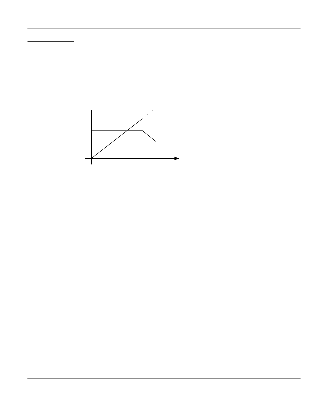
Figure 3-1 Speed Control
speed increase due to fieldweakening
Armature remains constant
Voltage 200V
Field Current 5.7A
field current reduced
base
speed
During speed control the speed of the motor can be increased by adjusting the motor field. Weakening the field
current allows an increase in motor speed beyond that normally achieved for the motor rated armature voltage.
Control and Communications
Some of the internal blocks of this control must be connected for your application. This means that you must
understand the application and how the software blocks should be connected to implement your design. The
block diagram in Appendix C shows the factory set connections. These diagrams assist in understanding this
concept and will be described next.
The Keypad (Operator Station) provides access to parameters, diagnostic messages, trip settings and full
application programming. The heart of the control is a microprocessor that provides advanced features such as:
• Complex control algorithms not achievable by simple analog techniques.
• Software configured control circuitry that uses standard software blocks.
• Serial link communications with other drives or a PC for advanced process systems.
armature voltage
Speed
To customize drive performance for optimum use, you may need to configure, or reroute software connections to
and from the drive’s inputs and outputs and to and from the drive’s software blocks. You can configure the drive
and change software block parameter values either using the keypad or with a personal computer (PC) running
the software package Workbench D (see MN794).
Getting Started 3-1MN792
Page 16
Local and Remote Modes
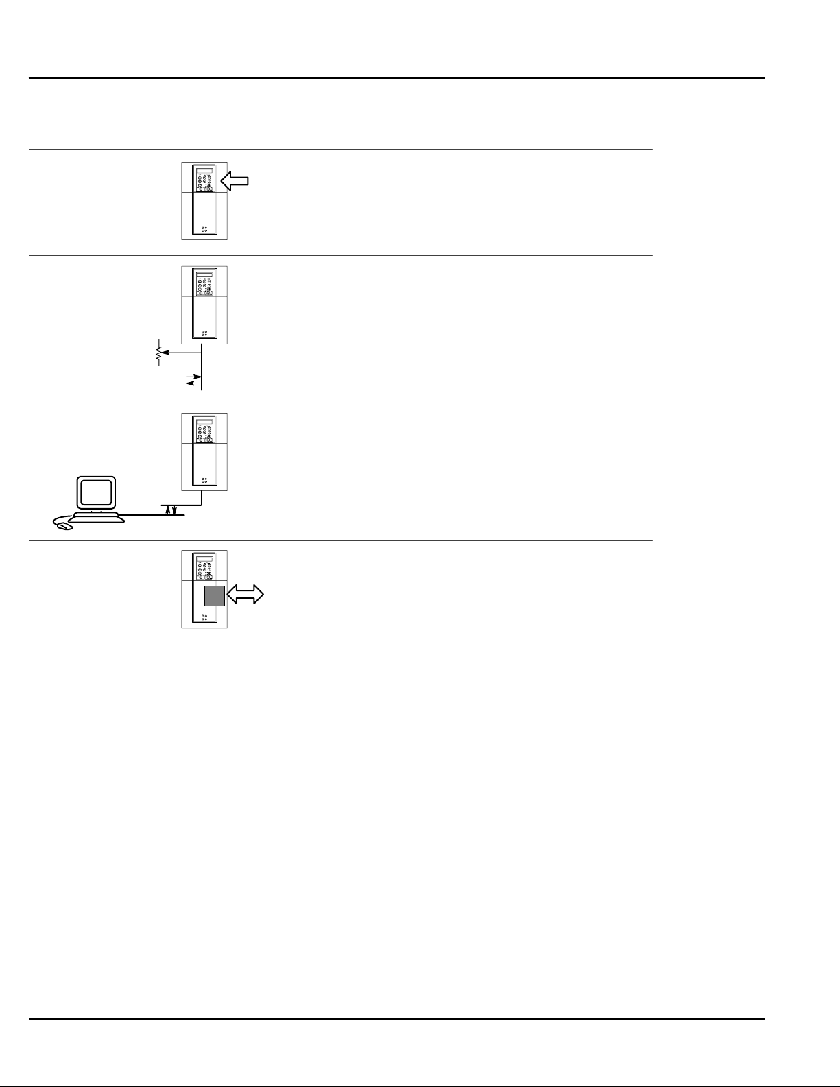
Determine what operating mode is best for your application. Four modes are possible, see Figure 3-2.
Figure 3-2 Local and Remote Modes
Local:
Keypad Setting
(Factory Setting)
Remote:
Terminal Strip Setting
Preset
Analog & Digital
Inputs and Outputs
Remote:
Serial Setting
Remote:
COMMS Setting
For local operation, use the keypad to change parameters or control operation.
Process control and other applications may require the control to be used in remote mode with
analog and digital input/output signals performing all control operations. The control is
configured in this mode from the factory.
Remote Serial mode is used to initially setup and configure the parameters of the control.
For applications that are controlled by a PC that is running suitable software. Workbench D is
recommended.
For Baldor RS485/Modbus, Profibus DP and DeviceNet.
Two forms of control are in operation at all times: Start/Stop Control and Speed Control. These are operate by
local or remote control.
Local
The keypad is used to set motor speed and other parameters. The Start, Stop and Jog keys then control motor
rotation.
Remote
A speed reference signal (pot) and the various analog and digital inputs and outputs are used for speed control
and rotation of the motor shaft.
3-2 Getting Started MN792
Page 17
Source / Destination Tags
The control is very flexible because of the programming capability. The software block diagram of the control is
shown in Appendix C. Each logic block has inputs and outputs. These I/O points are called “Tags” because
they have a tag number associated with it and shown in brackets “[tag]” . Some tags are read only values and
some are read/write. Besides setting the value of each parameter, its source or destination connections can be
programmed. This means you can connect inputs and outputs of logic blocks as you desire to implement your
application.
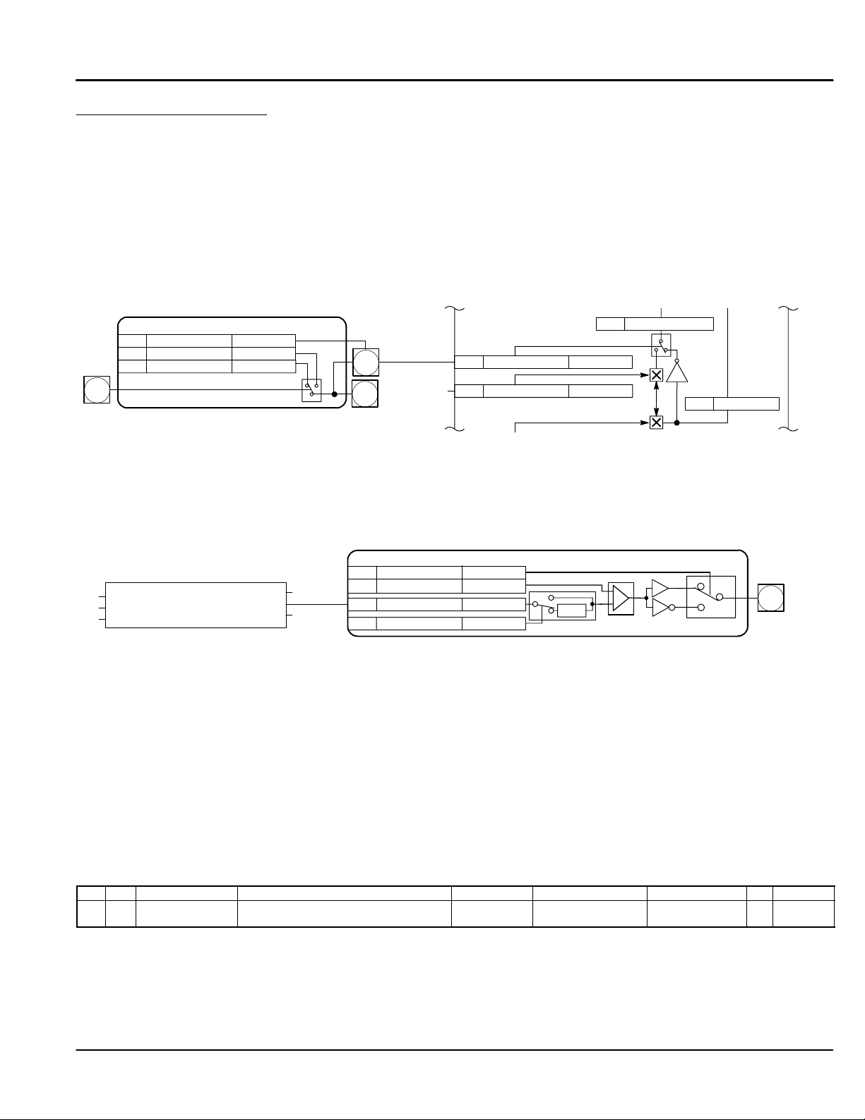
Destination Tag example
Consider Digital Input 1. The external connection (input) is made at the C connector pin 6. The block diagram of
this input is shown in Figure 3-3. Tag [102] is the destination tag for the output signal. The destination is
presently set to 90. This connects the output of Digital Input 1 to the Bipolar Clamps [90] input of the Current
Loop Logic Block. The value of [102] Digital output is determined by the switch position, either the value of [103]
or [104] will be applied to the output as the input changes from false to true.
Digital Input 1 – DIGIN 1 (C6)
Tag Parameter Setting
[102] Destination Tag 90
[104] Value for False 0.00%
Digital
[103] Value for True 0.01%
Input 1
C6
Source Tag example
Consider Digital Output 1. The external connection (output) is made at the B connector pin 5. The block
diagram of this input is shown in Figure 3-4. Tag [97] is the source tag for the input signal. The source is
presently set to 77. This means that Digital output 1 receives its input signal from [77] At Zero Speed parameter
from the Standstill Logic Block. To connect Digital Output 1 to the At Zero Setpoint parameter, simply change
[97] Source Tag value from 77 to 78.
Standstill
[11] Standstill Logic
[12] Zero Threshold
At Zero Setpoint [78][306] Source Tag
At Zero Speed [77]
At Standstill [79]
Figure 3-3 Digital Inputs
Current Loop
[102]
[71]
Diagnostic
connection
[90] Bipolar Clamps Digital IN 1
[48] NEG I Clamp Analog IN 4
Figure 3-4 Digital Outputs
Digital Output 1 – DIOUT 1 (B5)
Tag Parameter
[359] Inverted False
[195] Threshold (>)
[97] Source Tag 77
[43] Modulus True
Setting
0.00%
ABS
[88] NEG I Clamp
-1
[87] POS I Clamp
B5
Digital
Output 1
From these examples, it is easy to see that several things are required to program the control.
1. First, you must understand the application and know how to implement it in the control parameters.
2. Second, layout all of the connections for your application using the block diagrams in Appendix C.
3. Third, program the connections and parameter preset values. To do this you will need to refer to the
Parameter Values in Appendix B. This will tell you where in the keypad menu system you can locate
each parameter value or [tag].
For example, find [97] in Appendix B, (see Figure 3-5). To locate [97] using the keypad, begin at the System
menu, select Configure I/O menu, then select Digital Outputs menu, finally select Digital Output 1 (B5)
parameter. Change the value of that parameter to the desired value.
Note: Tag number “[97]” is not shown at the keypad for the Digital Output 1 (B5) parameter value. To display
the [TAG] number of the parameter, display the parameter value then press the “M” key to show the
parameters tag number. Appendix B and C are the key to programming your application.
Figure 3-5
Table B-1 Parameters Listed by Tag Number
Tag R/W Name Keypad Menu WB Block Range Factory Setting MN Notes
97 RW Source Tag SYSTEM::CONFIGURE I/O::DIGITAL
OUTPUTS::DIGOUT 1 (B5)
4. Select the next parameter and repeat step 3.
Digout 1 (B5) 0 to 549 77 cp 2, 3
Continued
Getting Started 3-3MN792
Page 18
Programming Block A very important step to installing this control is to determine the configuration that will best implement your
application. Each input and output of each block has an assigned tag number. Tags are connected in software
much like jumper wires are used in hardware. The control is shipped with a factory set software connection.
This may be changed at any time. The method of changing these connections (source or destination tags) is
described later in the programming Section 6 of this manual.
Note: It is important to correctly set the software to implement your application in the most efficient way. Some
parameters are Tags (connections) and others are programmed values. Be careful when programming
to be sure the correct input or output is being set.
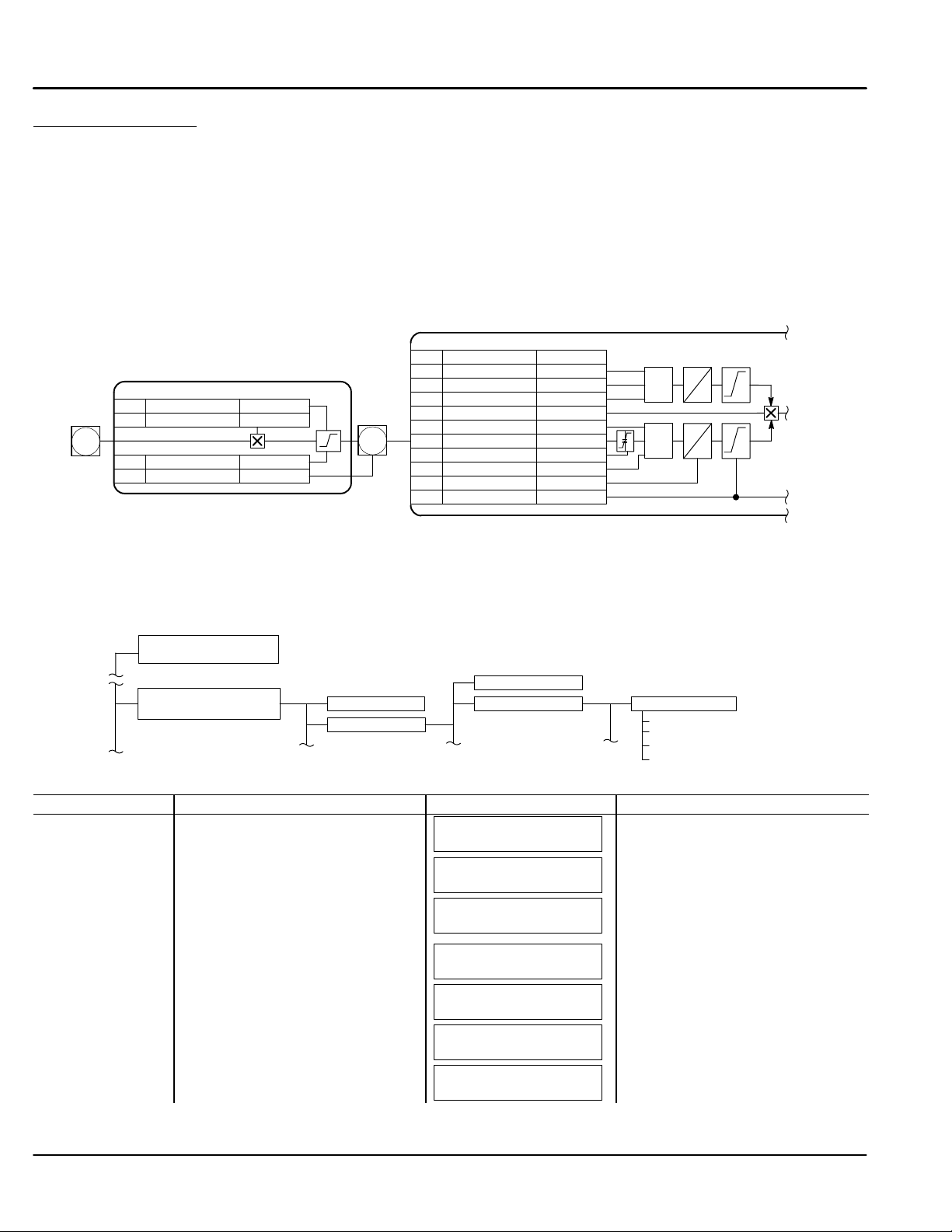
Example (View Analog Input 1 parameter settings)
As an example, a portion of the block diagram is shown in Figure 3-6. The output of Analog Input 1 [246] is
connected to [100] “Input 1” of Setpoint Sum 1 block. Each input and output shown on these diagrams is
programmable.
Figure 3-6 Analog Input Example
Setpoint Sum 1
Analog
Input 1
A2
Analog Input 1 – ANIN 1 (A2)
Tag Parameter
[231] Max Value +100.00%
[230] Calibration 1.0000
[232] Min Value -100.00%
[246] Destination Tag 100
Factory Setting
[246]
Tag Parameter
[292] Sign 0 Positive
[208] Ratio 0 1.0000
[309] Input 0 0.00%
[420] Divider 0 1.0000
[423] Input 2 0.00%
[6] Ratio 1 1.0000
[100] Input 1 0.00%
[131] Deadband Width 0.00%
[419] Divider 1 1.0000
[8] Sign 1 Positive
[375] Limit 105.00%
Factory Setting
A/B
A/B
+
-
+
+
+
+
-
The parameter values for Analog Input 1 can be changed at the keypad. Figure 3-7 shows a partial map of the
menu levels. The Analog Input 1 parameters are at Level 4 under the Level 3 Analog Inputs. The keypad
operation is shown in Table 3-1. Figure 3-7 can be used to visualize the menu structure that is being navigated
in Table 3-1.
Figure 3-7
1234
Diagnostics
Menu Levels
Configure Enable
System
Software
Configure I/O
Analog Inputs ANIN1 (A2)
Calibration
MAX Value
MIN Value
Destination Tag
Table 3-1 Set Analog Input 1 for 4–20mA
Action Description Display Comments
Apply Power Keypad Display shows this opening
message.
Press “PROG” key
Press M Access the menus.
Press Scroll to System menu. Press
several times.
Press M Access the System menus.
Press
Scroll to Configure I/O menu.
Press M Access Configure I/O menu.
FORWARD
REF: 0.00%
BALDOR DC DRIVE
DC 4Q 35A
MENU LEVEL
DIAGNOSTICS
MENU LEVEL
SYSTEM
SYSTEM
SOFTWARE
SYSTEM
CONFIGURE I/O
CONFIGURE I/O
CONFIGURE ENABLE
This message may be different for
each control.
This is menu level 1. Refer to Figure
3-7 for a description of the menu
levels.
This is menu level 1, System
parameters.
This is menu level 2.
3-4 Getting Started MN792
Page 19

Table 3-1 Set Analog Input 1 for 4–20mA Continued
Action
Description Display Comments
Press M Access Configure I/O menu.
Press
Change Configure Enable to Enabled.
Press E Access Configure I/O menu.
Press
Scroll to analog inputs menu.
Press M Access analog inputs 1 menu.
Press M Access Calibration menu.
Press M View or change the Calibration value.
Press E
Press
Scroll to next menu.
Press M View or change the MAX Value menu.
Press E
Press
Scroll to next menu.
Press M View or change the MIN Value menu.
Press E
Press
Scroll to next menu.
Press M View or change the Destination tag
Value menu.
Press E Press “E” several times to return to
the Configure Enable menu.
Press M Access Configure I/O menu.
Press M Access Configure I/O menu.
Press
Change Configure Enable to Disabled.
Press E
CONFIGURE ENABLE
DISABLE
CONFIGURE ENABLE
ENABLED
CONFIGURE I/O
CONFIGURE ENABLE
CONFIGURE I/O
ANALOG INPUTS
ANALOG INPUTS
ANIN1 (A2)
ANIN1 (A2)
CALIBRATION
CALIBRATION
1.0000
ANIN1 (A2)
CALIBRATION
ANIN1 (A2)
MAX VALUE
MAX VALUE
100.00%
ANIN1 (A2)
MAX VALUE
ANIN1 (A2)
MIN VALUE
MIN VALUE
–100.00%
ANIN1 (A2)
MIN VALUE
ANIN1 (A2)
DESTINATION TAG
DESTINATION TAG
100
ANIN1 (A2)
DESTINATION TAG
CONFIGURE I/O
CONFIGURE ENABLE
CONFIGURE ENABLE
ENABLED
CONFIGURE ENABLE
DISABLED
CONFIGURE I/O
CONFIGURE ENABLE
This is menu level 3. Before any
parameter values can be changed,
Configure Enable must be “Enabled”
(it is normally disabled”).
Note that the LED’s on Keypad are
flashing until changed back to Disable.
Move back one menu level using the
E key.
This is menu level 4.
Use the and keys to change the
value. Press E when finished.
Use the and keys to change the
value. Press E when finished.
Use the and keys to change the
value. Press E when finished.
Use the and keys to change the
value. Press E when finished.
This is menu level 2.
This is menu level 3. Before the
control can be used again, Configure
Enable must be “Disabled”.
Note when is pressed, the keypad
will briefly display “calibrating”
followed by Disabled and all Keypad
LED’s stop blinking.
Press the “E” key several times to move back through the menu items or press “PROG” to return to control operation.
Note: When changing a numeric value, pressing the “M” key will change the cursor position one digit to the left.
Getting Started 3-5MN792
Page 20

3-6 Getting Started MN792
Page 21

Section 4
Receiving and Installation
Receiving & Inspection
Baldor Controls are thoroughly tested at the factory and carefully packaged for shipment. When you receive
your control, there are several things you should do immediately.
1. Observe the condition of the shipping container and report any damage immediately to the
commercial carrier that delivered your control.
2. Remove the control from the shipping container and remove all packing materials. The container and
packing materials may be retained for future shipment.
3. Verify that the part number of the control you received is the same as the part number listed on your
purchase order.
4. Inspect the control for external physical damage that may have been sustained during shipment and
report any damage immediately to the commercial carrier that delivered your control.
5. If the control is to be stored before use, be sure that it is stored in a location that conforms to
published storage humidity and temperature specifications stated in this manual.
Location Considerations The location of the control is important. Installation should be in an area that is protected from direct
sunlight, corrosives, harmful gases or liquids, dust, metallic particles, and vibration. Exposure to these can
reduce the operating life and degrade performance of the control.
Several other factors should be carefully evaluated when selecting a location for installation:
1. For effective cooling and maintenance, the control should be mounted vertically on a smooth
non-flammable surface.
2. At least 1.0 inches (25mm) top and bottom clearance must be provided for air flow. At least 0.4
inches (10mm) clearance is required between controls (each side).
3. Operating Altitude derating. Up to 1640 feet (500 meters) no derating required. Derate the
continuous and peak output current by 1% for each 660 feet (200 meters) above 1640 feet.
Maximum operating altitude 16,500 feet (5,000 meters).
4. Operating Temperature derating. 0°C to 45°C (Sizes 1, 2); 0°C to 40°C (Sizes 3,4,5) ambient.
Above rated temperature, derate the continuous and peak output current by 2% per °C above rating.
Maximum ambient is 55°C.
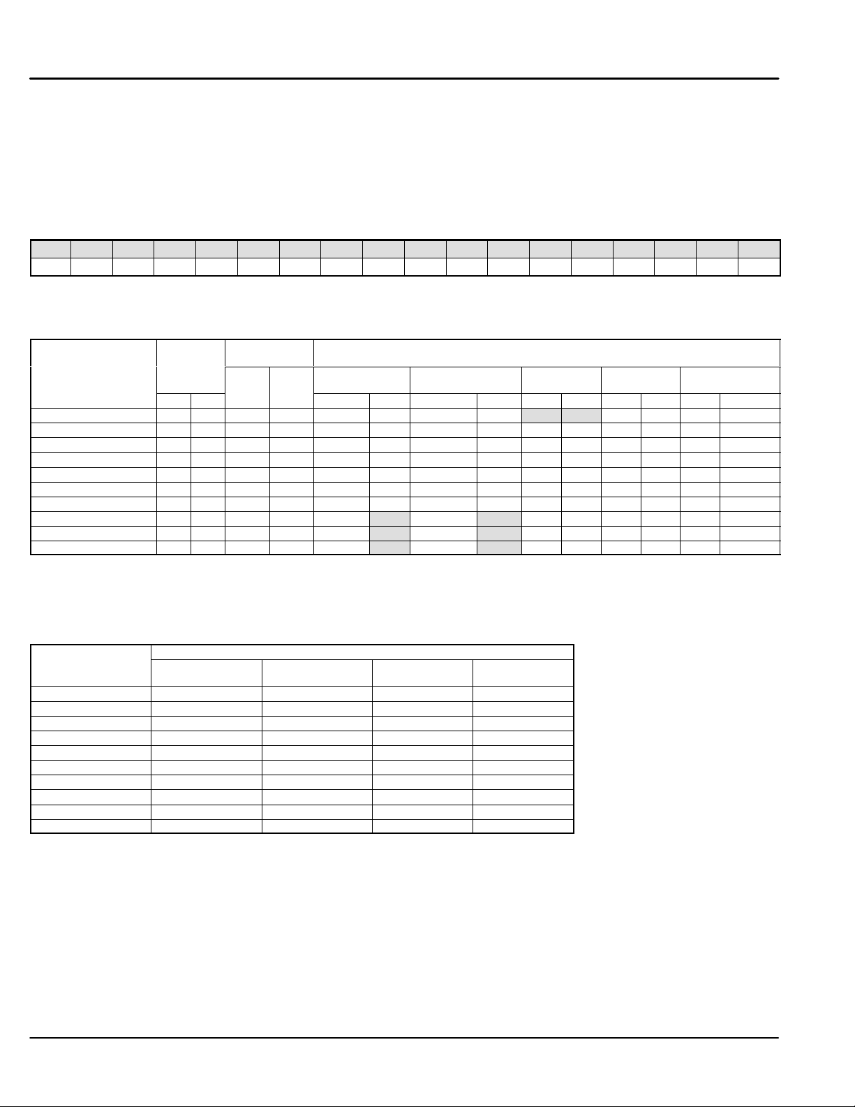
Table 4-1 Watts Loss Ratings
Catalog No. Output
Current (A)
BC29D7A35–CO7 35 117 BC29D7A380–CO1/CO2 380 1230
BC29D7A70–CO7 70 234 BC29D7A500–CO1/CO2 500 1590
BC29D7A110–CO7 110 354 BC29D7A725–CO1/CO2 725 2265
BC29D7A165–CO7 165 519 BC29D7A830–CO1/CO2 830 2580
BC29D7A243–CO1/CO2 243 840 BC29D7A1580–CO1/CO2 1580 4890
Watts Loss
(W)
Catalog No. Output
Current (A)
Watts Loss
(W)
Receiving & Installation 4-1MN792
Page 22
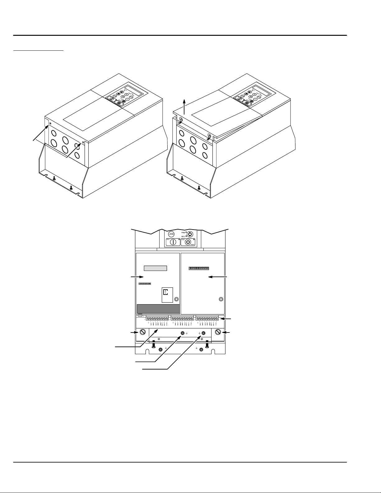
Cover Removal To connect power and signal wires, the cover must be removed. This procedure describes how to access all
terminal connections inside the control.
1. Loosen the two cover screws shown in Figure 4-8, then lift and remove the cover as shown.
Figure 4-1 Top Cover Removal
Lift and
remove cover
Cover
Screws
(2)
2. Locate the two 1/4 turn screws shown in Figure 4-2. Rotate each screw 1/4 turn CCW. This releases
the control from the base.
Figure 4-2 Signal Connections
Feedback Expansion
Board location
1/4 Turn Screw 1/4 Turn Screw (1/4 turn to release,
Power Connections (Control and base must
be opened to view, see Figure 4-9)
Power Ground
Motor Ground
Communications Expansion
Board location
Signal Connections
press screw into hole to close).
See Recommended Tightening Torques in Section 9.
4-2 Receiving & Installation MN792
Page 23
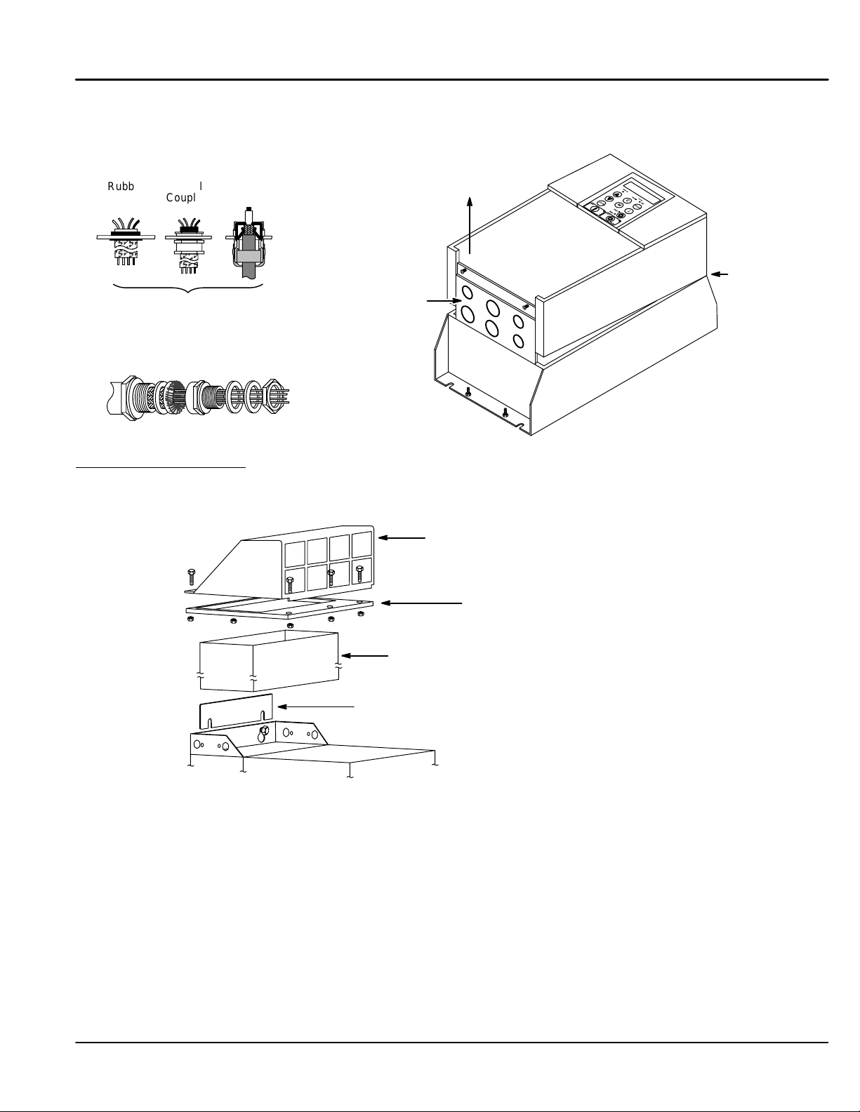
Cover Removal Continued
3. The control and base are hinged and are opened as shown in Figure 4-3.
Figure 4-3 Hinged Assembly
Rubber
Grommet
The knock–out panel is part of the base
assembly to allow connections to be made.
Use the correct size rubber grommet,
conduit coupling or 360 degree coupling.
Metal
Coupling
360 Degree Coupling
360 Degree
Coupling
Mechanical Installation
Mount the control to the mounting surface. The control must be securely fastened to the mounting surface by
the control mounting holes. The location of the mounting holes is shown in Section 9 of this manual.
External Vent Kit (Size 4 & 5 controls only)
Raise the control to
expose the base
Knock–out
panel
Hinge
Control
Base
Upper Housing
Foam gasket stretches over duct prior to
attaching upper housing.
Duct slides down between duct clip and mounting
panel and fits within the sides of the control housing.
Fit duct clip under fasteners at top of drive.
Be sure it is tight against the mounting panel.
Receiving & Installation 4-3MN792
Page 24
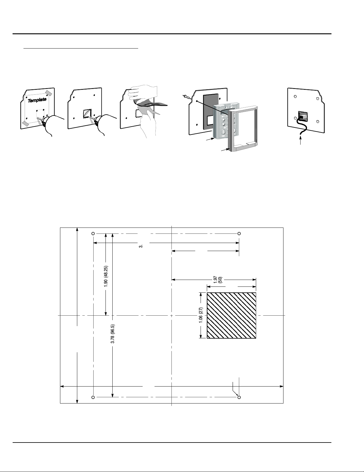
Optional Remote Keypad Installation (Enclosure rating of IP54 when correctly mounted). The keypad may be
remotely mounted using optional Baldor keypad extension cable.
Tools Required:
• Center punch, file and screwdrivers (Phillips and straight) and crescent wrench.
• #19 drill and drill motor .
Figure 4-4 Remote Keypad Installation
5
1
Mounting Instruction:
2
3
4
Keypad ACBD01A01
Bezel ACBD02A01
1. Locate a flat mounting surface. Place the template on the mounting surface (step 1).
2. Accurately center punch the mounting holes.
3. Drill holes for the two mounting screws.
4. Use the drill to remove metal for the 27 x 29 mm rectangular hole (step 2).
5. Debur the rectangular hole making sure the panel stays clean and flat.
6. Remove the protective film from the keypad gasket (step 3).
7. Assemble the keypad to the panel. Use two screws provided (step 4).
8. Connect the 10 ft. cable at the keypad and P3 of the control (step 5).
Figure 4-5 Template
CBLD030KP
4.09 (104)
1.90 (48.25)
3.78 (96.5)
3.40
(86.5)
5.22
(132.5)
1.57
1.06 (27)
(40)
1.97
(50)
1.14
0.16 (4.0) Dia.
(29)
Bottom
4 Places
4-4 Receiving & Installation MN792
Page 25
Electrical InstallationAll interconnection wires between the control, AC power source, motor, host control and any operator
interface stations should be in metal conduits. Use listed closed loop connectors that are of appropriate size for
wire gauge being used. Connectors are to be installed using crimp tool specified by the manufacturer of the
connector. Only class 1 wiring should be used.
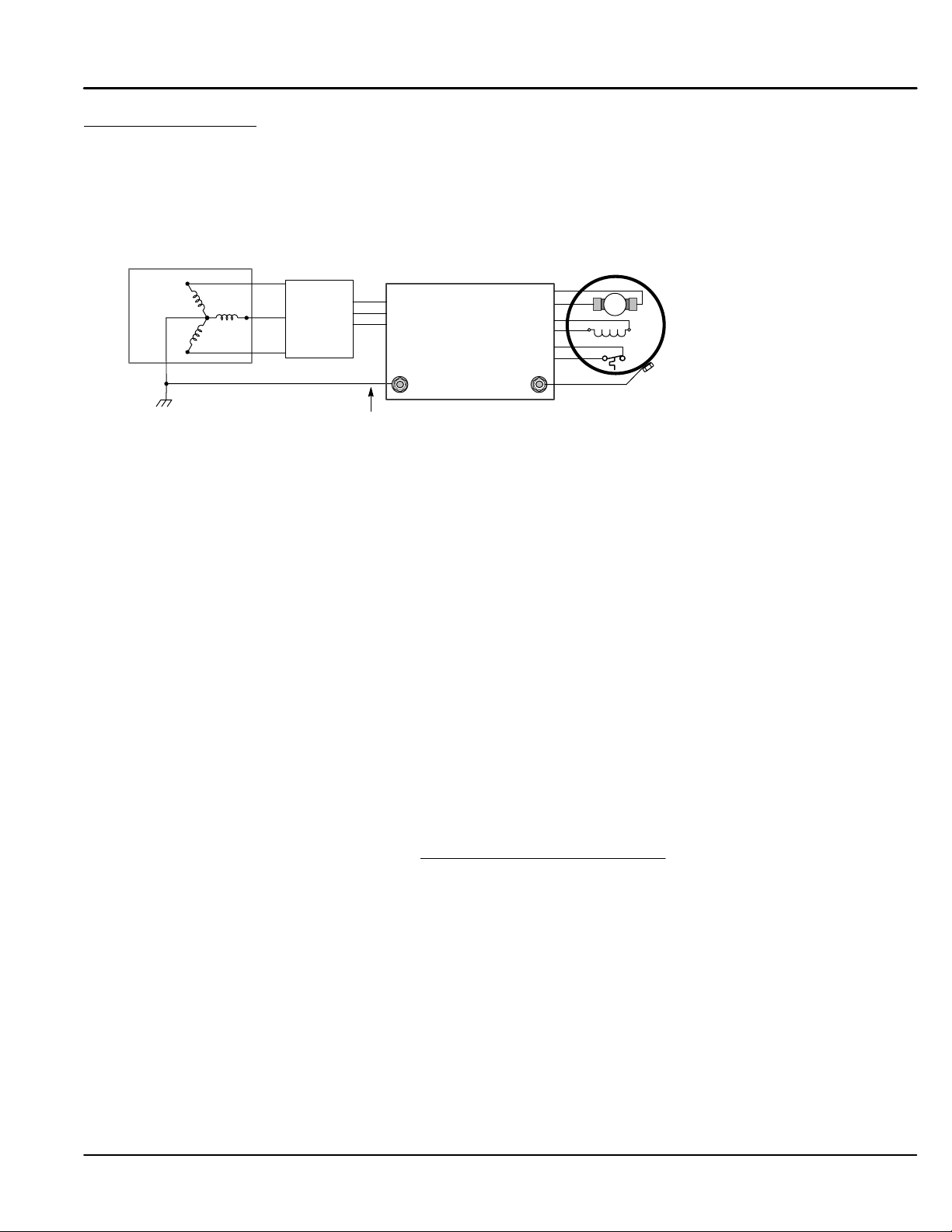
System Grounding Baldor controls are designed to be powered from standard single and three phase lines that are electrically
symmetrical with respect to ground. System grounding is an important step in the overall installation. The
recommended grounding method is shown in Figure 4-6.
Figure 4-6 Recommended System Grounding (3 phase) for UL
Note: Wiring shown for clarity of grounding method only. Not representative of actual terminal block location.
AC
Supply
(Mains)
Earth
Driven Earth Ground
(Facility Ground)
L1
Disconnect
L2
and Fuses
L3
Four Wire “Wye”
Route all power wires L1, L2, L3 and Earth
(Ground) together in conduit or cable.
L1
L2
L3
Control
TH1
TH2
A+
A–
F+
F–
Motor
See Recommended Tightening Torques in Section 9.
+
+
Armature
Field
Thermistor
GND
Ungrounded Distribution System
With an ungrounded power distribution system it is possible to have a continuous current path to ground through
the MOV devices. To avoid equipment damage, an isolation transformer with a grounded secondary is
recommended. This provides three phase AC power that is symmetrical with respect to ground.
Input Power Conditioning
Baldor controls are designed for direct connection to standard single and three phase lines that are electrically
symmetrical with respect to ground. Certain power line conditions must be avoided. An AC line reactor or an
isolation transformer may be required for some power conditions.
• If the feeder or branch circuit that provides power to the control has permanently connected power
factor correction capacitors, an input AC line reactor or an isolation transformer must be connected
between the power factor correction capacitors and the control.
• If the feeder or branch circuit that provides power to the control has power factor correction
capacitors that are switched on line and off line, the capacitors must not be switched while the control
is connected to the AC power line. If the capacitors are switched on line while the control is still
connected to the AC power line, additional protection is required. TVSS (Transient Voltage Surge
Suppressor) of the proper rating must be installed between the AC line reactor or an isolation
transformer and the AC input to the control.
Line Impedance The control requires a 5% maximum line impedance (voltage drop across the reactor is 5% when the control
draws rated input current). If the impedance of the incoming power does not meet the requirement for the
control, a 3 phase line reactor can be used to provide the needed impedance in most cases. Line reactors are
optional and are available from Baldor.
The input impedance of the power lines can be determined as follows:
Measure the line to line voltage at no load and at full rated load.
Use these measured values to calculate impedance as follows:
%Impedance +
(Volts
No Load Speed
(Volts
* Volts
No Load Speed
Full Load Speed
)
)
100
Power Disconnect A power disconnect should be installed between each input power source and the control for a fail–safe
method to disconnect power. The control will remain in a powered-up condition until all input power is removed
from the control and the internal voltage is depleted.
Protection Devices The control must have a suitable input power protection device installed. Input and output wire size is
based on the use of copper conductor wire rated at 75 °C. Table 4-3 describes the wire size to be used for
power connections and Table 4-4 describes the ratings of the protection devices.
Recommended fuse sizes are based on the following:
UL 508C suggests a fuse size of four times the continuous output current of the control.
Dual element, time delay fuses should be used to avoid nuisance trips due to inrush current when
power is first applied.
Receiving & Installation 4-5MN792
Page 26
Electrical Installation Continued
Isolation Transformer Sizing
Use the information in Table 4-2 to select the KVA rating of the transformer based on the HP rating of the
control. The secondary voltage will be the input voltage to the control and the impedance should be 2% or less.
One exception to Table 4-2 is when the DC armature voltage is less than the AC input voltage. If this is the
case, use the following formula:
KVA + 0.00163 VAC
Secondary
IDC
Secondary
Table 4-2 Isolation Transformer KVA Selection
HP 5 7.5 10 15 20 25 30 40 50 60 75 100 125 150 200 250 300
KVA 7.5 11 14 20 27 34 40 51 63 75 93 118 145 175 220 275 330
Single Phase Power Since the control rectifies all three input power phases, operation from a single phase power source is
not possible.
Table 4-3 Wire Size
Armature
Maximum
Catalog
Number
BC29D7A35-CO7 20 15 35 53 8 8.37 8 8.37 14 2.08 12-22 3.31-0.326
BC29D7A70-CO7 40 30 70 105 4 21.2 3 26.7 14 2.08 14 2.08 6-18 13.3-0.823
BC29D7A110-CO7 60 50 11 0 165 1 42.4 1/0 53.5 14 2.08 14 2.08 6-18 13.3-0.823
BC29D7A165-CO7 100 75 165 248 3/0 85.0 4/0 107.0 14 2.08 14 2.08 6-18 13.3-0.823
BC29D7A243-CO1/CO2 150 120 243 365 300kcmil 152 350kcmil 177 14 2.08 14 2.08 6-18 13.3-0.823
BC29D7A380-CO1/CO2 200 150 380 570 700kcmil 355 750kcmil 380 8 8.37 14 2.08 6-18 13.3-0.823
BC29D7A500-CO1/CO2 300 225 500 750 1250kcmil 634 1500kcmil 760 8 8.37 14 2.08 6-18 13.3-0.823
BC29D7A725-CO1/CO2 400 327 725 1088 1″x3″ BB* 1″x3″ BB* 8 8.37 14 2.08 6-18 13.3-0.823
BC29D7A830-CO1/CO2 500 335 830 1245 1″x3″ BB* 1″x4″ BB* 8 8.37 14 2.08 6-18 13.3-0.823
BC29D7A1580-CO1/CO2 900 650 1580 2370 2″x4″ BB* 2″x4″ BB* 8 8.37 14 2.08 6-18 13.3-0.823
Maximum
Output **
HP kW
Current
Cont. Peak
(Amps) (Amps)
3 AC Input Armature
AWG MM
2
AWG MM2AWG MM2AWG MM2AWG MM
* BB is copper Bus Bar.
** Hp and kW are approximate at 500VDC Armature voltage.
Note: All wire sizes based on 75°C copper wire, 40°C ambient temperature, 4-6 conductors per conduit or raceway.
Wire Size
Field Power
Supply
Logic Power
Supply
BL1,BL2,BL3
Table 4-4 Protection Devices
Catalog
Number
BC29D7A35-CO7 A60Q40 A70QS50-14F 4 3
BC29D7A70-CO7 A50QS80-4R A70QS80 10 3
BC29D7A110-CO7 A50QS125-4R A70QS150 10 3
BC29D7A165-CO7 A50QS175-4R A70QS200 10 3
BC29D7A243-CO1/CO2 A50QS300-4R A70P350 10 3
BC29D7A380-CO1/CO2 A070URD32KI0400 A130URD73LI0450 30 3
BC29D7A500-CO1/CO2 A070URD32KI0630 A130URD73LI0700 30 3
BC29D7A725-CO1/CO2 A070URD32KI0800 A130URD73LI0900 30 3
BC29D7A830-CO1/CO2 A070URD32KI0900 14URD93TTF1250 30 3
BC29D7A1580-CO1/CO2 A070URD32KI0900 * 12.5URD94TDF2300M 30 3
3 AC Line
(Ferraz–Shawmut)
(Ferraz–Shawmut)
* 6 fuses per drive.
Fuse Rating
Armature
Field Supply (A) Logic Supply (A)
2
4-6 Receiving & Installation MN792
Page 27
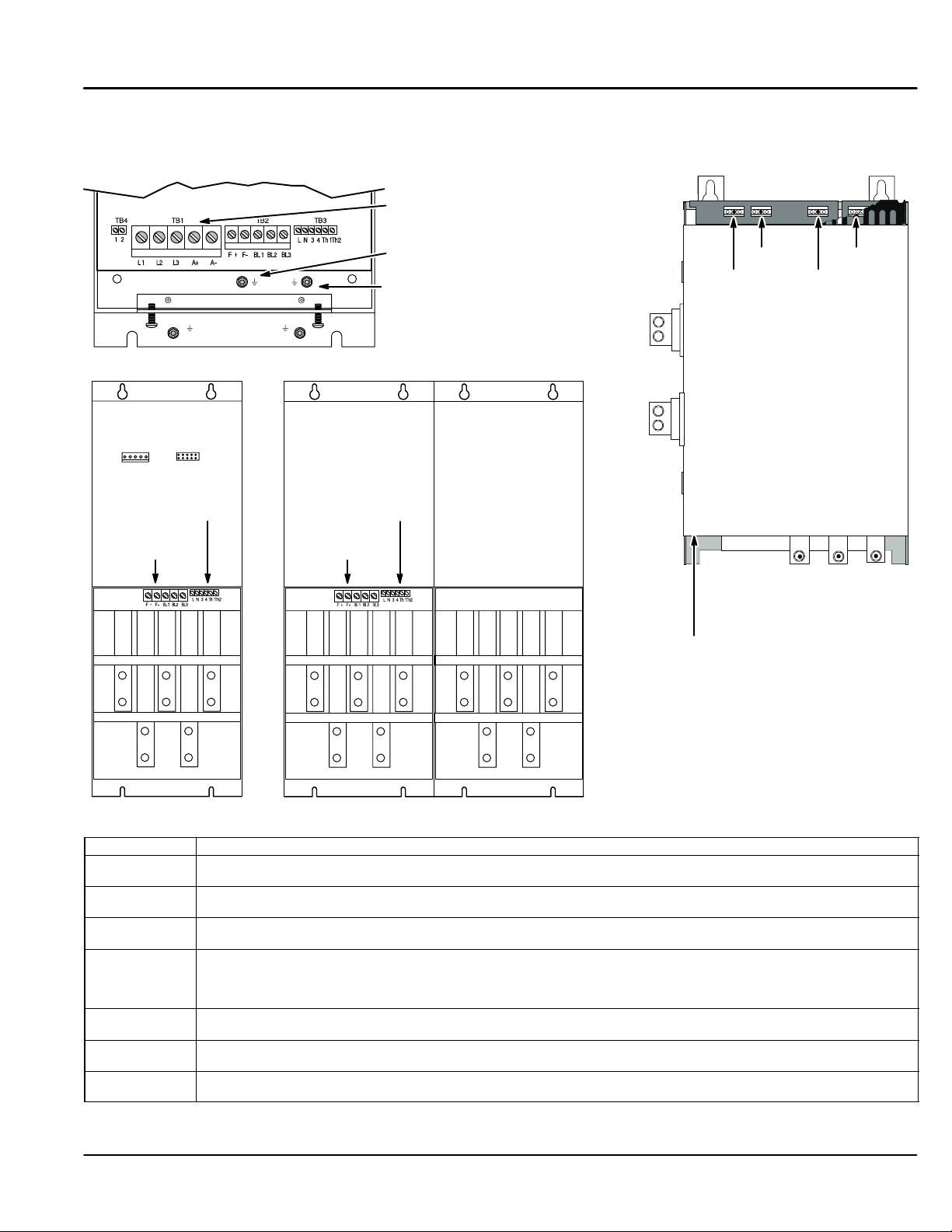
Electrical Installation Continued
Figure 4-7 Size 1–5 Power Terminal Locations
Size 1 and 2 Size 3
Power Connections
Size 4
Logic Supply,
Contactor &
Thermistor
Connections
Field
Connections
L1 L2 L3
AC Main Supply
Motor Ground
Logic Supply,
Contactor &
Thermistor
Connections
Field
Connections
L1 L2 L3
Earth from
Size 5
L1 L2 L3
D1, D2
A+
A–
THERM+ and
THERM– are
on separate bd.
in door assembly
D3, D4
D1 = FL1
D2 = FL2
D3 = F–
D4 = F+
D5 = 3
D6 = 4
D7 = N
D8 = L
D7, D8
D5, D6
L1 L2 L3
A+
A-
A+
A+
A-
A-
See Recommended Tightening Torques in Section 9.
Table 4-5 Power Connector Signals
Terminal Description
L1, L2, L3 Main AC input power. A 3–phase AC contactor should be connected in the main AC power supply connections.
A+, A– The motor armature is connected to busbar terminals A+ and A–. If a DC contactor is used the contactor poles
F+, F– Connect the motor field (–) to terminal F– and field (+) to terminal F+. If the motor has no field connections, is a
FL1, FL2 An external field supply may be used for Size 2–5 controls. Connect this supply to terminals FL1 and FL2. The
3, 4 Size 3–5, the AC Contactor coil can be connected between TB3–3 (line) and TB3–4 (neutral) and its purpose is to
L, N Single phase AC power for logic circuits. The auxiliary supply must be connected directly to the incoming supply,
TH1, TH2 Connection for motor thermal protection. Thermistors must have a combined working resistance of 750 ohms or
(AC Contactor is internal for Size 1 and 2 controls. For other sizes, use terminals 3 and 4).
should be interposed between the control terminals and the motor terminals.
permanent magnet motor, or if the field is derived externally, you must disable the Field Enable [170] parameter.
voltage is determined by the desired field voltage. The supply must be protected externally with suitable fuses.
Always derive the supply from the Red and Yellow phases of the main power supply, with the Red phase
connected to terminal FL1 and the Yellow phase connected to FL2.
provide AC power disconnection. Maximum coil inrush current must not exceed 3A.
(disconnect only). (Logic Supply is internal for Size 1 and 2 controls).
less, increasing to at least 4k ohms at over–temperature. The alarm is latched and the contol must be restarted.
Receiving & Installation 4-7MN792
Page 28
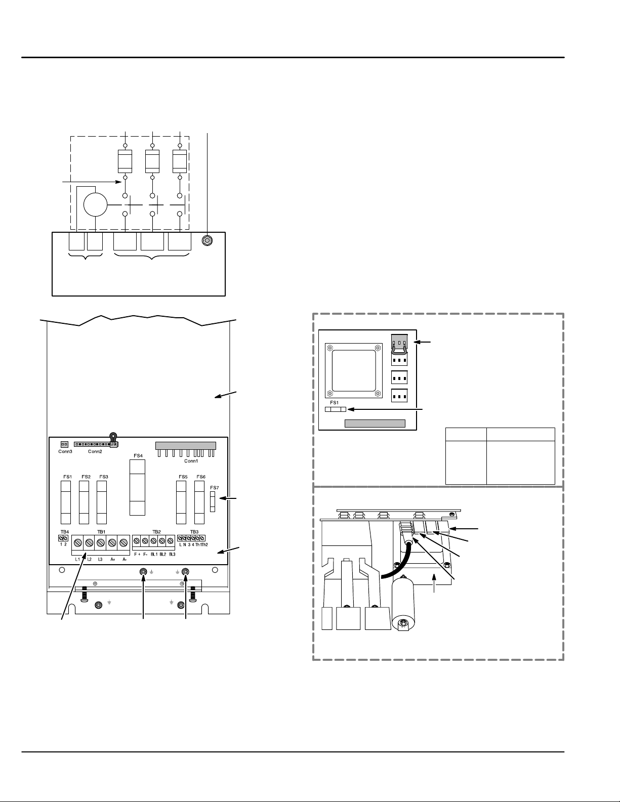
Electrical Installation Continued
Power Connections Single phase operation of this control is not possible.
Power connections are shown in Figure 4-8. (The location of these terminals is shown in Figure 4-9).
Figure 4-8 3 Phase Power Connections
Note 1
Note 2
Start
Contactor
Fuse
Connection
RE
3
4
L1 L2 L3
L1 L2 L3
Earth
Note 3 & 4
Note 6
Notes:
1. See Protection Device description in this section.
2. Metal conduit or shielded cable should be used. Connect conduits so
the use of a Reactor or RC Device does not interrupt EMI/RFI shielding.
3. Use the same gauge wire for Earth as used for L1, L2, L3 connections.
4. Use same gauge wire for Earth ground as is used for L and N,
or L1, L2 L3. (VDE (Germany) requires 10mm
6AWG).
5. Reference EMC wiring in Appendix A for CE compliance.
6. AC Contactor is internal for size 1 and 2 controls. Size 3–5, the
contactor can be connected between TB3–3 (line) and TB3–4
(neutral) and its purpose is to provide AC power disconnection.
Maximum inrush current must not exceed 3A.
2
minimum,
TB3
Baldor Control
Figure 4-9 Size 1 & 2 Internal Logic Transformer Jumper Locations
TB1
Logic Trans.
Location
Size 1
FS7
Logic Trans.
Location
Size 2
This figure shows optional components not furnished with control.
See Recommended Tightening Torques in Section 9.
Size 1 control
Logic
Transformer
Conn1
Conn2
Conn3
Conn4
Conn5
Move the jumper to the
correct voltage of the
480
L1,L2,L3 supply input.
400
Note: When the internal logic
230
208
transformer is installed, FS7
on the main board is
removed. FS1 on the logic
supply board is used.
FS1
Setting
480
400
230
208
Voltage Range
460–500
380–415
220–240
208
Size 2 control
208
230
400
480
Logic
Transformer
Power
Connections
AC Main Supply
Motor GroundEarth from
Move the jumper to the
correct voltage of the
L1,L2,L3 supply input.
(480V position shown.)
See Recommended Tightening Torques in Section 9.
Logic Power For size 1 and 2 controls, the logic transformer is internal. The location is shown in Figure 4-9. Because the
logic transformer is powered from the L1,L2,L3 input AC power, the jumper must be placed in the location that
corresponds to the AC line voltage.
For size 3, 4 and 5 controls the single phase logic power must be supplied by an external source. Normally
115VAC is applied at TB3 terminals L and N, see Figure 4-7 for the location. (Your control may have been
ordered with 230VAC logic power. In that case, 230VAC is applied at TB3 terminals L and N.)
4-8 Receiving & Installation MN792
Page 29
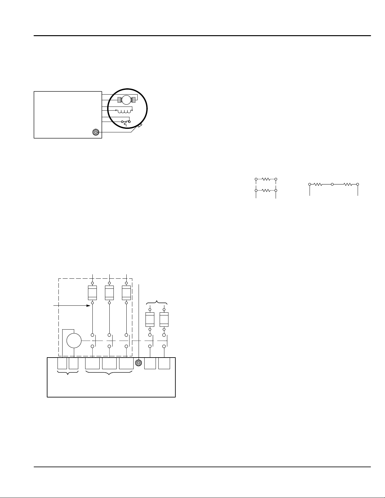
Electrical Installation Continued
Motor Connections Motor connections are shown in Figure 4-10. (The location of these terminals is shown in Figure 4-9).
Note: If your motor requires more than 85% of the line voltage as its DC input voltage, a step up transformer is
required. This is added between the incoming line terminals and the L1 and L2 terminals of the field
supply module. This connection is phase sensitive with main input L1 and L2.
Figure 4-10 Motor Connections
Notes:
1. Shield wires inside a metal conduit.
2. Metal conduit should be used to shield output
wires (between control and motor). Connect
conduits for continuous EMI/RFI shielding.
See Recommended Tightening Torques in Section 9.
Control
TH1
TH2
A+
A–
F+
F–
Motor
+
+
Armature
Field
Thermistor
GND
Note: The control may be connected to a permanent magnet field DC motor. In this case, the field supply is not
connected and the “Field Enable” [170] parameter must be set to “Disable”.
Shunt Wound
Typical shunt wound motor field connection 120/240V or
150/300V. Consult manufacturers specific motor data for details.
See Recommended Tightening Torques in Section 9.
External AC Field (Not available for size 1 controls)
The internal motor field is more widely used, it provides up to 90% of rated AC main voltage to the field
windings. However if an external field supply is required (an application that requires more field voltage than
90% of AC main), terminals FL1 and FL2 can be used. The magnitude of this voltage is determined by the
desired field voltage. The external supply must be protected with suitable fuses and disconnect. Always derive
the supply from the Red and Yellow phases of the main power supply, with the Red phase connected to FL1
and the Yellow phase to FL2 (see jumpers in the External Field Connections diagrams).
Figure 4-11 External Field Connections
L1 L2 L3
Note 3 & 4
Earth
FL1 FL2
External
Field Supply
Note 1
Note 2
Start
Contactor
Note 6
Fuse
Connection
RE
3
4
TB3
Baldor Control
L1 L2 L3
TB1
F1 F2
F1 F4F2 F3
F3 F4
120V or 150V
Notes:
1. See Protection Device description in this section.
2. Metal conduit or shielded cable should be used. Connect conduits so
the use of a Reactor or RC Device does not interrupt EMI/RFI shielding.
3. Use the same gauge wire for Earth as used for L1, L2, L3 connections.
4. Use same gauge wire for Earth ground as is used for L and N.
(VDE (Germany) requires 10mm
2
minimum, 6AWG).
5. Reference EMC wiring in Appendix A for CE compliance.
6. AC Contactor is internal for size 1 and 2 controls. Size 3–5, the
contactor can be connected between TB3–3 (line) and TB3–4
(neutral) and its purpose is to provide AC power disconnection.
Maximum inrush current must not exceed 3A.
This figure shows optional components not furnished with control.
See Recommended Tightening Torques in Section 9.
240V or 300V
Receiving & Installation 4-9MN792
Page 30
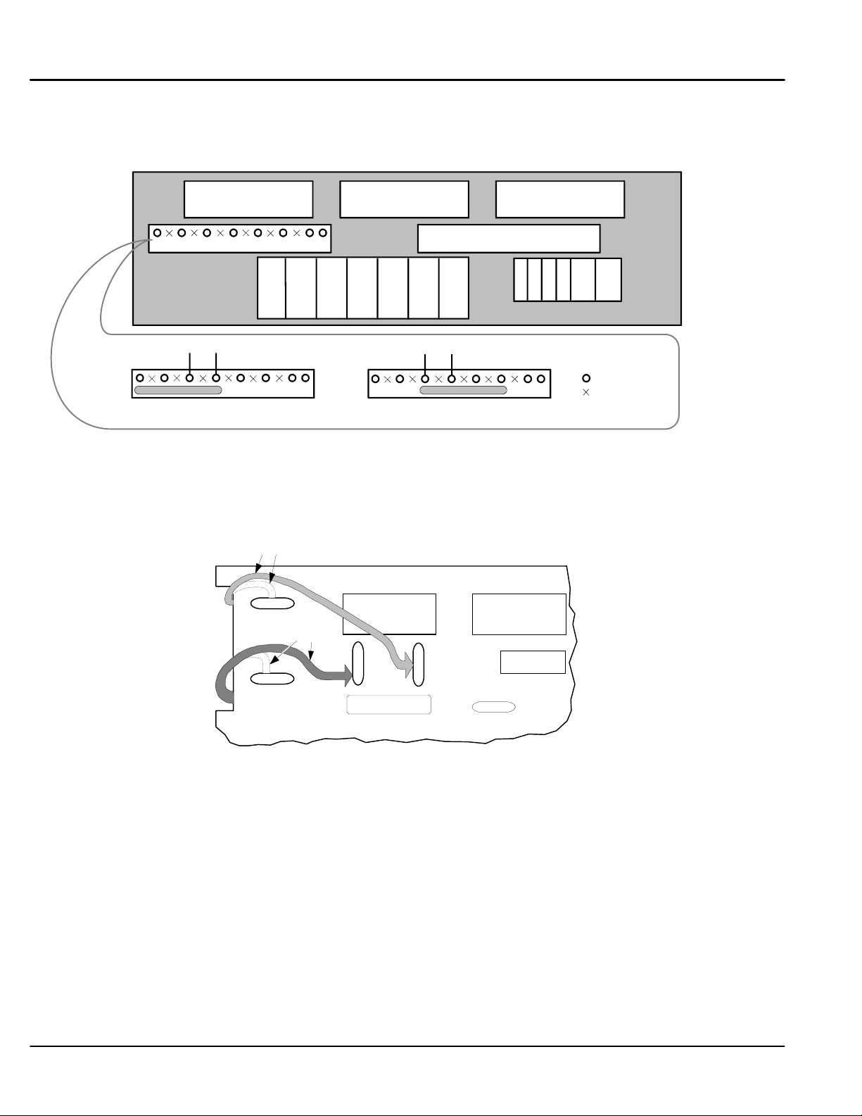
Electrical Installation Continued
External Field Terminal and Jumper Locations – Size 2
The position of the jumper selects the board to use either an internal or external motor field.
Figure 4-12 External Field Sensor Plug Jumper Settings
PLG1 to Power Board PLG2 to Power Board PLG3 to Power Board
External Field Selector Plug
FL1 FL2 F+ F– M1 M2 M3
Field Bridge
FL1 FL2
Jumper selecting external field supply Jumper selecting internal field supply
L1 L2
FL1 FL2
External Field Terminal and Jumper Locations – Size 3
Relocating the Red and Yellow phase wires (as shown in Figure 4-13) allows terminals D1 and D2 on the Power
Board to be used as the external field AC supply connections. External fuse must not exceed 10A.
Figure 4-13 External Field Connections
Yellow
D1
F8
Red
F19
F16
Motor Vent Fan Circuit Breaker
Field Bridge
Power Board
D2
F18
L N 3 4 TH1 TH2
Terminal Board
L1 L2
Connection
No Connection
See Recommended Tightening Torques in Section 9.
D3
D4
F8 & F16 = Internal Field Supply.
F18 & F19 = External Field Supply.
Red = FL1
Yellow = FL2
Procedure:
1. Remove the control board (2 screws secure it) to allow access to the power board.
2. Remove the red phase lead from connector “F16” on the left–hand side of the board.
3. Connect the red phase lead to connector “F19” located below D1.
4. Remove the yellow phase lead to connector “F8” on the left–hand side of the board.
5. Connect the yellow phase lead to connector “F18” located below D2.
6. Connect L1 to D1, and L2 to D2. When using an external AC input it is important to have the correct
phase relationship on the terminals. The supply must be derived from L1 (Red) and L2 (Yellow)
phases directly or indirectly through a single phase transformer. L1 must be connected to D1, and L2
connected to D2.
4-10 Receiving & Installation MN792
Page 31

Electrical Installation Continued
External Field Terminal and Jumper Locations – Size 4 and 5
Relocating the Red and Yellow phase wires (as shown in Figure 4-14) allows terminals FL1 and FL2 to be used
as the external field AC supply connections. External fuse must not exceed 30A.
Figure 4-14 External Field Connections
Red
red
F4
F4
F5
F5
F6
F6
F1
F1
F14
F13
F13
F14
F3
EX A– EX A+
EX A– EX A+
Procedure:
1. Remove the control board (2 screws secure it) to allow access to the power board.
2. Remove the red phase lead from connector “F2” on the left–hand side of the board.
3. Connect the red phase lead to connector “F3” located near the EX L1 terminal.
4. Remove the yellow phase lead to connector “F5” on the left–hand side of the board.
5. Connect the yellow phase lead to connector “F6” located near the EX L2 terminal.
6. Connect L1 to FL1, and L2 to FL2. When using an external AC input it is important to have the
correct phase relationship on the terminals. The supply must be derived from L1 (Red) and L2
(Yellow) phases directly or indirectly through a single phase transformer. L1 must be connected to
FL1, and L2 connected to FL2.
F3
F2
F2
EX L1
EX L1
Yellow
ye llow
EX L2
EX L2
FL1 FL2 F+ F–
FL1 F L2 F+ F–
F2 & F5 = Internal Field Supply.
F3 & F6 = External Field Supply.
Red = FL1
Yellow = FL2
M-Contactor If required by local codes or for safety reasons, an M-Contactor (motor circuit contactor) may be installed.
However, incorrect installation or failure of the M-contactor or wiring may damage the control. If an M-Contactor
is installed, the control must be disabled for at least 20msec before the M-Contactor is opened or the control
may be damaged. M-Contactor connections are shown in Figure 4-15.
Figure 4-15 Optional M–Contactor Connections
A+
A–F+ F–
*
F+
M=Contacts of optional M-Contactor
* M
F–
+
Control faults may occur if the control is enabled before the M Contactor is closed. The timing diagram shown in
Figure 4-16 defines the correct operating sequence.
At Turn ON
Allow 20 milli seconds for the coil of the M contactor to energize and close the contactor before the Enable input
at C–4 is issued.
At Turn OFF
Do not allow the M Contactor to open until motor shaft rotation has stopped and the Enable at C–4 has been
removed. If this sequence does not occur, a TACH LOSS fault may be issued by the control.
Note: This example shows a “Drive ON” output to a PLC that is used to command the DC control and the
holding brake.
To Customer Provided
Power Source
(Rated Coil Voltage)
*
M Enable
* M-Contactor
C
3
4
5
Note: Close “Enable”
after “M” contact closure.
See Recommended Tightening Torques in Section 9.
* Optional
RC Device
Electrocube
RG1781-3
Receiving & Installation 4-11MN792
Page 32

Electrical Installation Continued
Figure 4-16 M Contactor Operation Sequence
Turn-ON
M Contact
20 msec.
Enable
Motor Flux
“Drive ON”
Output
Mech. Brake Release
(If user installed)
50 msec.
Speed/Torque
Command
Blower Motor Starter Optional Size 1 and 2 controls only.
Size 1 and 2 controls can be equipped with an optional blower motor starter that uses a manual motor circuit
controller to provide motor overload and branch circuit protection for a single or three phase AC blower motor.
The starter assembly is fully wired and ready for site installation. This option offers
Branch circuit protection
Instantaneous magnetic short circuit protection
Thermal overload protection, Class 10, with adjustable trip current settings
Start/Stop/Reset switching with “tripped“ pushbutton indication
Normally open auxiliary contact wired into the drive logic to indicate “Motor Overtemperature“ trip
Installation
1. Open the cover to view the fuse board (Figure 4-3).
2. Position the starter assembly horizontally across the top of the drive so that the harness points
downward toward the power terminals.
3. Align the bracket with its mounting slots on the inside walls of the drive. Snap into place with a firm
push until the tabs engage.
4. Locate the 14 pin header for the blower motor starter connections.
For size 1, this connector is CONN 2, located at the top left corner of the fuse board.
For size 2, this connector is CONN 44 located at the right edge of the terminal board.
5. This connector has a jumper installed at the right most two pins. Remove and save this jumper.
6. Plug the 14 pin connector from the blower motor starter onto this connector.
7. Use a small screwdriver to set the full load current of the blower motor on the dial of the blower motor
starter.
8. Connect the blower motor leads to terminals BL1, BL2, BL3 (Figure 4-7).
9. Press the Start button on the blower motor starter. Installation is now complete.
Run Time
Turn-OFF
Brake Set Time
4-12 Receiving & Installation MN792
Page 33

Electrical Installation Continued
Thermal Protection Terminals TB3 TH1 and TH2 are available for connection to a normally closed thermostat or overload
relay in all operating modes as shown in Figure 4-17. The thermostat or overload relay should be a dry contact
type with no power available from the contact. If the motor thermostat or overload relay activates (opens), the
control will automatically shut down and give an Thermistor fault. The optional relay (CR1) shown provides the
isolation required and the N.O. contact is closed when power is applied to the relay and the motor is cold. If the
motor thermostat is tripped, CR1 is de-energized and the N.O. contact opens.
Connect the motor thermal wires (N.O. relay contact) to TH1 and TH2. Do not place these wires in the same
conduit as the motor power leads.
Figure 4-17 Motor Temperature Relay
If the motor thermostat is not used,
TH1 and TH2 must be jumpered
together to allow operation.
See recommended terminal
tightening torques in Section 9.
* Motor
Customer Provided
Source Voltage
*
CR1
Motor Thermostat Leads
Note: Add appropriately rated protective
device for AC relay (snubber)
or DC relay (diode).
TB3
TH1
TH2
Do not run these wires in same conduit
as motor leads or AC power wiring.
* Optional hardware. Must be ordered separately.
Thermostat
See Recommended Tightening Torques in Section 9.
Encoder Installation Electrical isolation of the encoder shaft and housing from the motor is required. Electrical isolation
prevents capacitive coupling of motor noise that will corrupt the encoder signals. Baldor provides shielded wire
for encoder connection. Table 4-6 defines the encoder connections to the encoder receiver expansion board.
Figure 4-18 shows the electrical connections of the encoder. The expansion board is installed in the feedback
EXB location shown in Figure 4-2.
1. Open the top cover (Figure 4-1).
2. Align the 10 pin connector on the board with the connector on the left side of the control.
3. Carefully push the encoder board into position being careful not to bend any pins. All four stand–offs
should contact the control.
4. Connect the encoder wires to the expansion board, see Table 4-6 and Figure 4-18.
Table 4-6 Encoder Connection Descriptions
Description Encoder Connector
No.
A A 3
A A 4
B B 5
B B 6
C C
C C
+VCC Supply +VCC Supply 2
Not used (VCC Sensor) Not used (VCC Sensor)
0VDC 0VDC 1
Not used (0VDC Sensor)
Cable Shield
Encoder Receiver
Board Pin.
To Encoder
Figure 4-18 Differential Encoder Connections
Align the 10 pin connector to the 10 pin connector
of the control (see Figure 4-2 for location). Carefully
seat the board onto the pins until all four standoffs
contact the control surface.
0VDC (Isolated)
+VCC (Isolated)
Channel A
Channel A
Channel B
Channel B
Encoder Case
Encoder
Expansion
Board
Potentiometer (VCC Adjust)
Torque to 3.5 lb-in (0.4Nm)
16-22AWG
Receiving & Installation 4-13MN792
Page 34

Electrical Installation Continued
Tachometer Installation The tachometer expansion board can be used to connect either an AC Tach or a DC Tach to the
control (only one may be used). Shielded wire must be used for tachometer connection. Table 4-7 defines the
tachometer connections to the tachometer expansion board. Figure 4-19 shows the electrical connections of
the tachometer. Figure 4-20 shows the settings for this board.
Note: DC Tachometers provide speed and direction feedback. AC tachometers provide only speed feedback.
Table 4-7 Tachometer Connection Descriptions
Description Tachometer Receiver
AC Tach Input 1
AC Tach Input 2
DC Tach Input + 3
DC Tach Input – (0VDC) 4
Board Pin.
Figure 4-19 Tachometer Connections
Align the 10 pin connector to the 10 pin connector of the
control (see Figure 4Ć2 for location). Carefully seat the board
onto the pins until all four standoffs contact the control surface.
To AC Tach
OR
To DC Tach
Tachometer
Expansion
Board
G1G2G3G
4
Torque to 5.3 lb-in (0.6Nm)
Figure 4-20 Switch Settings
Calibration
Switches
The jumper is always used. It plugs onto the control PCB in just about the
position shown. This jumper is where the actual scaled signal connects from
the Tach board to the controller PCB.
For full speed tach voltages greater than 200V, an external resistor of value
RE must be used in series with the DC Tach connection at G3. The value
RE is calculated as follows:
SW1 = Ones calibration switches.
SW2 = Tens calibration switches.
SW3 = Down adds 100 VDC in the down position (100's position).
SW4 = Up for AC Tach; Down for DC Tach.
As shown, switches are set for 188VDC for a DC tach:
(SW3 + SW2 + SW1 = 100 + 80 + 8 = 188)
SW1
SW2
SW4
AC
DC
SW3
SW4
SW4
1"
10"
0
100"
Jumper
RE ohms =
(Max Tach Volts * 200)
5
kW
RE Watts = (Max Tach Volts * 200) 5 milliwatts
G1 G2 G3 G4
Torque to 5.3 lb-in (0.6Nm)
In general, the voltage output of an analog AC or DC tachometer generator is a function of speed and is rated in
volts per 1000 RPM so that:
Speed Feedback Voltage
(volts) + Motor Speed
Max
(RPM) x Tach Rating
Max
The Tach Rating should be on the nameplate of the tachometer generator. Fine tuning is performed within the
software (refer to the Speed Feedback Calibration). If the full speed feedback voltage exceeds 200 VDC, use an
external resistive scaling network to drop the feedback voltage to within this range.
For AC tachometer generators, the switch settings will be about 1.3 times greater than the voltage measured at
the input terminals G1 and G2 due to the rectifier offset. For example, for 90V feedback, the switch setting is:
Ǹ
2
Required Voltage Feedback + 2Ǹ 90 + 127V
.
4-14 Receiving & Installation MN792
Page 35

Control I/O Signal Connections
All connections made to terminal blocks A, B and C must be isolated signal voltages. If in doubt a connection,
contact Baldor. Only shielded, twisted pair cables should be use. Minimum wire size is 18AWG (0.75mm2). All
cables should be installed using the appropriate coupling in the knock out panel, shown in Figure 4-3.
Analog Inputs Five analog inputs are available, AnIn1 – AnIn5 (AnIn4 and AnIn5 are factory set for current limits).
Connector
Terminal
A1 0V common reference point for all analog signals.
A2 Analog Input 1. 0–20 or 4–20mA analog input speed input. Used as a unipolar 0–20mA ramped speed command
A3 Analog Input 2. ±10V analog input speed or torque reference without Accel/Decel ramps. +10V = maximum forward
A4 Analog Input 3. ±10V analog input speed or torque reference with Accel/Decel ramps.
A5 Analog Input 4. Optional Negative Current Clamp. Inactive until Bipolar Clamps parameter is set to Enable. When
A6 Analog Input 5. External Current Limit / Optional Positive Current Clamp. A jumper is supplied from B3 (+10V Ref) to
Signal Description
channel. 4–20mA requires manually setting Min value to 25%, Max Value to 125% and setting Setpoint Sum1, Input
2 to (–)25%. These settings will provide the proper scaling and offset to set 4mA to zero command. Any input less
than 4mA will result in a Min Value of 25% being added to (–)25% at the Setpoint Sum 1 summing junction.
speed demand. –10V = maximum reverse speed demand.
Closing C8 (Digital Input 3) selects Torque Command Mode by enabling the IDMD Isolate input (Current Loop Block).
Opening C8 selects Speed Command Mode by disabling the IDMD Isolate input.
In all cases this analog command channel bypasses the Ramps Block.
By closing the Reverse input at C5, the direction of the unipolar command can changed. Output of Ramps block is
connected to Setpoint 1 of the Speed Loop block. Various voltage range, and bipolar or unipolar commands can be
accepted by adjusting Calibration, Max Value, and Min Value parameters of Analog Input 3.
enabled, this input is the value of the negative current limit.
A5 to allow full rated 150% current. When Bipolar Clamps parameter is set to Disabled, this input is the main current
limit value. When Bipolar Clamps parameter is set to Enable, this input value is the positive or
forward current limit.
Note: The settings for AnIn1 – AnIn5 are factory set but can be changed to suit your application.
Speed Setpoint
The speed demand signal can be generated using an external 10K potentiometer as shown in Figure 4-21. The wiper is the
speed reference.
AB
0V 1
AnIn 1 2
AnIn 2 3
AnIn 3 4
Control I/O
AnIn 4 5
Connectors
A1
0-20 mA or
4-20 mA Input
500
A2
0–10VDC or ±10VDC Input
0–10VDC or ±10VDC Input
See Recommended Tightening Torques in Section 9.
0V
AnIn1
Control
Figure 4-21 Analog Inputs
AnIn 5 6
AnOut 1 7
AnOut 2 8
0V 1
DigOut 1 5
Arm I Fbk 9
Not Used 2
DigOut 2 6
-10V Ref 4
+10V Ref 3
Multiple Speed Setpoints
A1
A3
A4 AnIn3 Speed Setpoint 2 (Ramped)
0V
AnIn2 Speed Setpoint 1 (Non-Ramped)
Control
C
DigOut 3 7
Prog Stop 8
Coast Stop 9
Command Pot
0V 1
Ext Trip 2
10KW
Start 3
DigOut E 4
DigIn 1 6
DigIn 2 7
DigIn 3 8
DigOut R 5
Analog GND
Analog Input
Pot Reference
+24V 9
Setpoint Ramp Input
A1
A4
B3 +10VDC
0V
AnIn3
Control
Receiving & Installation 4-15MN792
Page 36

Control I/O Signal Connections Continued
Analog Outputs
Connector
Terminal
A7, A8, A9 Three analog outputs are available, AnOut1 – AnOut3. A1 is the 0V common reference point.
Signal Description
Figure 4-22 Analog Outputs
Analog Outputs
A10V
AnOut1
AnOut2
Control
A7
A8
A9Arm I Fbk
Analog Output 1 (±10VDC)
Analog Output 2 (±10VDC)
Analog Output 3 (±10VDC)
See Recommended Tightening Torques in Section 9.
Digital Inputs C4 (Enable) must be connected to C9 (+24V) to allow the drive to run when start command is given.
Connector
Terminal
B8 Program Stop. When opened runs a decel rate set by Stop Rates, Prog Stop Time.
B9 Coast Stop. When opened disables the drive output.
C2 External Trip. When opened disables the drive output and creates an External Trip Fault.
C3 Start/Stop. Closed initiates a Start/Run forward sequence. When opened commands Stop and decels at Stop Rates,
C4 Enable. Closed enables the drive and allows output to the motor.
C5 Reverse. Closed changes the slope of the speed command signal from Analog Input 1 and Analog Input 2.
C6 Jog / Slack.
C7 Jog/Slack Mode. See Jog/Slack description in Section 6 for description of modes.
C8 Speed/Torque Select. Open selects speed (velocity) mode. Closed selects current (torque) mode.
Signal Description (factory settings)
Stop Time setting.
Accomplished by activating the “Ramp Invert” input of the Ramps block.
If terminal C4 is closed and Start/Stop terminal C3 is open, motor will be commanded to run forward at Jog Speed 1.
If terminal C4 is closed and Start/Stop terminal C3 is closed, motor will be commanded to run forward at active speed
setpoint plus Jog/Slack Take Up 1 speed. Various Jog or Slack take–up functions Various Jog or Slack take–up
functions are commanded depending on the various settings of terminals C3, C4 and Jog/Slack Mode C7.
Accel/Decel ramps are not used in Torque mode.
Start (C3), Enable (C4), Reverse (C5), Program Stop (B8) and Coast Stop (C9).
The basic Run/Start sequence is initiated by C3 (Start/Run). Other safeguards are provided by B8 (Program
Stop) and B9 (Coast Stop). Assuming that the Program Stop and Coast Stop terminals are held TRUE, then a
single contact connected between C9 (+24V) and C3 (Start/Run) when closed will cause the control to
energize the Main Contactor and when C5 (Enable) is also TRUE the motor will rotate.
When the single contact to C3 (Start/Run) is opened, the controller will decelerate the motor to zero speed at a
rate determined by the STOP TIME parameter value and the MAIN CURR. LIMIT value. If the load is to be
serviced, the control must be securely disabled and isolated, do not rely on this mode.
4-16 Receiving & Installation MN792
Page 37

Control I/O Signal Connections Continued
Figure 4-23 Run/Stop Connections
B8 Program Stop
B9 Coast Stop
Emergency Stop Relay (Optional)
(Shown in energized - Run position)
C3
C4
C5 Reverse
C6
C7
C8 Speed/Torque Select
C9
RE
Start
Enable
Jog/Slack
Jog/Slack Mode
+24VDC
Control
See Recommended Tightening Torques in Section 9.
A regenerative drive can be stopped using a Normal Stop, a Program Stop, or an Emergency Stop.
Normal Stop
If the +24V is removed from C3 during operation, the control will cause the motor to stop at a rate determined by
Stop Limit, Stop Time and Curr. Limit.
Program Stop
If the +24V is removed from B8 during operation, the control will cause the motor to stop at a rate determined by
Prog Stop I Lim, Prog Stop Limit and Prog Stop Time. If +24V is re–applied to B8, the motor remains stationary
until a new Start command is applied to C3 (Start/Run).
Coast Stop
If the +24V is removed from B9 during operation, the control will remove power to the motor and the motor and
load will coast to a stop.
Emergency Stop (Optional)
When the “Emergency Stop Relay” is de–energized its contacts disconnect +24VDC from the inputs shown in
Figure 4-23. The control will remove power to the motor and the motor and load will coast to a stop. The
emergency stop relay should not be part of the normal sequencing of the system, but is an emergency operation
when safety is the main concern. If the load is to be serviced, the control must be securely disabled and
isolated, do not rely on this mode.
Digital Outputs
Connector
Terminal
B5, B6, B7 Three digital outputs are available, DigOut1 – DigOut3. B1 is the 0V common reference point.
Signal Description
These digital output terminals provide a +24VDC output signal under certain conditions. An LED, Lamp, Relay
or other device can be connected at these outputs to indicate the condition of control operation. These are
configurable outputs and can be used as required in the control system design, i.e. panel lamps, connection to a
suitable PLC. Simply connect a 24VDC relay between the output and B1 (0VDC). Be sure to use a reverse
biased diode or other noise elimination device across the relay coil, see Figure 4-24.
Figure 4-24 Optional Digital Output Relay Connection
Note: Add appropriately rated protective
B5
CR1
B1
device for AC relay (snubber)
or DC relay (diode).
Receiving & Installation 4-17MN792
Page 38

RS232 Connections The keypad connector shown in Figure 4-25 is used for RS232 communications. Workbench D is the
1 SERIAL LINKS
2 SYSTEM PORT P3
block programming software for Windows PCs. It has a graphical user interface and drawing tools to allow you
to create block programming diagrams quickly and easily.
Figure 4-25 System Port (P3) Keypad Connector
3 P3 SETUP
MODE
P3 BAUD RATE
Control
(DCE)
1234
View into the connector.
A null modem cable (also called a modem eliminator cable) must be used to connect the control and the
computer COM port. This will ensure that the transmit and receive lines are properly connected. Either a 9 pin
or a 25 pin connector can be used at the computer, Figure 4-26. Maximum recommended length for RS232
cable is 10 ft. (3 meter).
Figure 4-26 9 & 25 Pin RS-232 Cable Connections
9 Pin Connector
25 Pin Connector
RXD
TXD
GND
Chassis
Null Modem Cable Connections
RXD
TXD
GND
Computer
COM
Port
(DTE)
Pin Signal
2 RXD
3 TXD
5 GND
Pin Signal
3 RXD
2 TXD
7 GND
Table 4-8 Cable Connections
P3 Connector DB Connector Type and Pin Number
Pin Signal Name DB9 DB25
1 GND/0VDC 5 7
2 24VDC
3 RXD 2 3
4 TXD 3 2
System Port (P3) Configuration
The factory port settings are normally fine. These settings are:
9600 Baud
8 Bits
1 Stop Bit
No Parity
XON/XOFF Handshaking (fixed)
If the port settings must be changed, attach a keypad to the control and change the settings under the P3
SETUP menu. Refer to Keypad Operation for additional information to make these parameter value changes.
4-18 Receiving & Installation MN792
Page 39

Section 5
Switch Setting and Start-Up
Pre–Operation Checks
Size 4 and 5 Only – Power Board Calibration
Power Board
IF CAL
SW2
When the installation is complete, several things should be verified before power is applied.
1. Be sure AC power is off at the main disconnect or circuit breakers.
2. Measure the main AC supply voltage (to the disconnect or breaker) and verify that it matches the
nameplate rating of the control.
3. If the catalog number on the nameplate ends with “CO1”, an external 115VAC logic control supply is
required (C02= 230VAC Logic). Verify Auxiliary power supply voltage is correct.
4. Verify the armature voltage and current ratings of the motor are correct.
5. Inspect all power connections (line and motor) for accuracy, workmanship tightness and compliance
to codes.
6. Verify that the control and motor are grounded to each other and that the control is connected to
earth ground.
7. Verify all signal wiring for accuracy and tightness.
8. Be certain that all contactor, brake or relay coils have noise suppression. This should be an RC filter
for AC coils or a reverse biased diode for DC coils. MOV type transient suppression is not adequate.
9. Disconnect the load from the motor shaft if possible.
10. If possible, verify the motor shaft rotates freely.
11. Verify the cooling fan (blower) is free from obstruction.
12. Verify that the external run contacts are open.
13. Verify that external speed setpoints are all zero.
IA CAL – Armature Current Calibration Switch (SW1)
This switch is always set to LO on Frame 4 & 5 drives of less than 500A, and HI for drives greater
than 500A.
F CAL – Field Current Calibration Switch (SW2)
This switch should always be set to HI for Frame 4 & 5 drives. The maximum field current calibration
is 30A.
HI
LO
IA CAL
SW1
HI
LO
Power up in Local Mode with Armature Feedback
When pre–operation checks are complete, logic power can be applied to terminals L and N to setup the
software parameters (catalog number C01=115VAC, C02=230VAC). For other catalog numbers (100hp and
less), the logic power is provided internally so 3 phase power must be applied at this time.
(The start up mode is defined by Parameter [517] =True for keypad operation which is the same as “SETUP
PARAMETERS::OP STATION::START UP VALUES::LOCAL = TRUE”.)
Note: To separate the various menu level designation, a double colon is used (SETUP PARAMETERS::OP
STATION).
1. Apply logic power.
2. Verify that the keypad and LED’s display correctly. If not, verify that the logic wiring is correct.
Action Description Display Comments
Apply Logic Power
at terminals L and N
Keypad Display shows this opening
message.
If [517] is True, local mode will be
displayed (factory setting)
INITIALIZING
BALDOR DC DRIVE
CALIBRATING
FORWARD
REF: 0.00%
LED’s are all ON.
LED’s are flashing. After several
seconds the next screen is displayed.
The OK, SEQ, REF, FWD and STOP
LED’s are on.
Switch Setting & Start-Up 5-1MN792
Page 40

Power up in Local Mode with Armature Feedback Continued
3. Set the parameter Configure Enable to “Enabled”.
Action Description Display Comments
Apply Logic Power Keypad Display shows this opening
message.
Press “PROG” key
Press “M” key
Press “M” key Access the menus.
Press
Scroll to “Configure Drive” menu.
Press “M” key Access Configure Drive menu.
Press “M” key Access the Configure Enable
parameter.
Press
Enable Configure Enable.
Press “E” key Returns to previous menu level.
FORWARD
REF: 0.00%
BALDOR DC DRIVE
DC 4Q 35A
DC 4Q 35A
MENU LEVEL
MENU LEVEL
DIAGNOSTICS
MENU LEVEL
CONFIGURE DRIVE
CONFIGURE DRIVE
CONFIGURE ENABLE
CONFIGURE ENABLE
DISABLED
CONFIGURE ENABLE
ENABLED
CONFIGURE DRIVE
CONFIGURE ENABLE
LED’s are flashing. After several
seconds the next screen is displayed.
All LED’s are now flashing.
Press “E” when done.
4. Set the Nominal Motor Volts (Armature Voltage) in the Configure Drive menu.
Action Description Display Comments
Press
Press “M” key Access the NOM Motor Volts
Press “PROG” key
Scroll to the NOM Motor volts
parameter.
parameter
CONFIGURE DRIVE
CONFIGURE ENABLE
CONFIGURE DRIVE
NOM MOTOR VOLTS
NOM MOTOR VOLTS
180 VOLTS
Press to change to current control if
desired. Press “E” when done.
5. Set the Armature Current. Note the maximum armature current from the motor name plate and set
this value in the Armature Current parameter.
Action Description Display Comments
Press
Press “M” key Access the Armature Current
Press “PROG” key
Scroll to the Armature Current
parameter.
parameter
CONFIGURE DRIVE
CONFIGURE ENABLE
CONFIGURE DRIVE
ARMATURE CURRENT
ARMATURE CURRENT
11.5 AMPS
Press to change to current control if
desired. Press “E” when done. Max
value is hardware limited.
Note: Holding the M key scrolls the
cursor the left most digit so it can be
changed more quickly.
5-2 Switch Setting & Start-Up MN792
Page 41

Power up in Local Mode with Armature Feedback Continued
6. Set the Field Current. Note the nominal field current from the motor rating plate and set this value in
the Field Current parameter.
Action Description Display Comments
Press
Press “M” key Access the Field Current parameter
Press “PROG” key
Action Description Display Comments
Press several
times
Press “M” key Access the field control mode
Press “PROG” key
Scroll to the Field Current parameter.
CONFIGURE DRIVE
CONFIGURE ENABLE
CONFIGURE DRIVE
FIELD CURRENT
FIELD CURRENT
0.2 AMPS
Press to change to current control if
desired. Press “E” when done. Max
value is hardware limited.
7. Set the Field Control Mode to Field Voltage or Field Current control. Refer to section 6 for more
information. The factory setting is Voltage Control mode.
Scroll to the field control mode
parameter.
CONFIGURE DRIVE
CONFIGURE ENABLE
CONFIGURE DRIVE
FLD CTRL MODE
FLD CTRL MODE
VOLTAGE CONTROL
Press to change to current control if
desired. Press “E” when done.
8. Set the Field Volts Ratio. Enter the calculated ratio into the parameter given by the equation: A
setting of 90% is the maximum value obtainable, i.e. field output = 0.9 x VAC
FieldVolts (Nameplate)
100
Input Volts AC
RMS
Action Description Display Comments
Press
Press “M” key
Press “M” key Access the menus.
Press
Scroll to the field volts ratio parameter.
Scroll to “Configure Drive” menu.
CONFIGURE DRIVE
FLD CTRL MODE
CONFIGURE DRIVE
FLD VOLTS RATIO
FLD VOLTS RATIO
0.00%
CONFIGURE DRIVE
FLD VOLTS RATIO
Press to increase the value if
desired. Press “E” when done.
9. Set the Configure Dive::Configure Enable parameter to disable (see step 3).
10. Save the settings.
Action Description Display Comments
Start at Menu
Level 1
Press
Scroll to “PARAMETER SAVE” menu.
Press “M” key
Press Press to save parameters.
Press “E” key Exit one level
MENU LEVEL
DIAGNOSTICS
MENU LEVEL
PARAMETER SAVE
PARAMETER SAVE
UP TO ACTION
PARAMETER SAVE
REQUESTED
MENU LEVEL
PARAMETER SAVE
Parameters are saved. Except the
“Local Setpoint”.
Press “E” several times to return to
the top level.
Switch Setting & Start-Up 5-3MN792
Page 42

Power up in Local Mode with Armature Feedback Continued
The control is now ready to run from the keypad using armature feedback.
1. The logic power is still applied, the keypad display is normal, the motor is connected but the load is
removed.
2. Apply 3 phase power.
3. Verify that the keypad and LED displays are still normal, with no error messages.
4. Set the Speed Setpoint parameter to zero.
5. Verify that the Main CURR. Limit is set to 0.00%. View ANIN 5 (A6) parameter in the level 1
Diagnostics menu and verify it displays 0.00V.
6. Press JOG at the keypad. Verify that 3–phase mains is applied to Power Terminals L1, L2 and L3
and immediately check that the correct field voltage appears between the control supply terminals F+
and F–. If the field voltage is not correct, check one of the following:
Internally Supplied Field:
a. Check that 3–phase is applied to terminals L1, L2 and L3 when the main contactor is closed.
b. Check that the fuses on the power board or supression board are healthy.
c. Verify the Field Enable parameter is set to Enable.
d. Is the FLD CTRL Mode parameter set to Voltage Control or Current Control?
If set to VOLTAGE CONTROL, check the value of the FLD. VOLTS RATIO parameter. Set this
to 65% to obtain 300V fields from 460V lines.
If set to CURRENT CONTROL, check the field current calibration.
If the field volts are at maximum, check the field continuity. (The field current may initially be
less than the rated value due to a cold field.)
Externally Supplied Field: (not available for size 1and 2 controls)
a. Refer to Chapter 4 Installation, Motor Field Connections for conversion details.
b. Check the voltage applied (externally fused) to terminals FL1 and FL2.
c. Check the phasing of voltage applied to FL1 and FL2:
FL1 must be connected directly or indirectly to the Red phase on main power terminal L1.
FL2 must be connected directly or indirectly to the Yellow phase on main power terminal L2.
d. Verify the Field Enable parameter is set to Enable.
e. Is the FLD CTRL Mode parameter set to Voltage Control or Current Control?
If set to Voltage Control, check the value of the FLD. Volts Ratio parameter. Set this to 65% to
obtain 300V fields from 460V lines.
If set to Current Control, check the field current calibration set–up, refer to “Calibration”.
7. Verify that the OK and STOP LEDs are On, also either the FWD or REV LED.
This verifies keypad operation of the control and motor. The control may be used in this mode after the load is
connected or additional wiring changes can be made for operation from the terminal strip.
5-4 Switch Setting & Start-Up MN792
Page 43

Power up in Remote Mode with Feedback This procedure assumes that the terminal strip (connectors A, B C) are wired
according to the instructions provided in Section 4 and the feedback device is properly installed. (The start up
mode is defined by Parameter [517] =False for remote operation which is the same as “SETUP
PARAMETERS::OP STATION::START UP VALUES::LOCAL = FALSE”.)
When pre–operation checks are complete, logic power can be applied to setup the software parameters. At this
point, 3 phase power should remain off, if possible.
1. Apply Logic power.
2. Verify the keypad and LED’s display correctly. If not, verify that the logic wiring is correct.
Action Description Display Comments
Apply Logic Power Keypad Display shows this opening
message.
The local mode (keypad mode) is
displayed
BALDOR DC DRIVE
CALIBRATING
FORWARD
REF: 0.00%
3. Set the parameter Configure Enable to “Enabled”.
Action Description Display Comments
Apply Logic Power Keypad Display shows this opening
message.
Press “PROG” key
Press “M” key
Press “M” key Access the menus.
Press
Scroll to “Configure Drive” menu.
Press “M” key Access Configure Drive menu.
Press “M” key Access the Configure Enable
parameter.
Press
Enable Configure Enable.
Press “E” key Returns to previous menu level.
FORWARD
REF: 0.00%
BALDOR DC DRIVE
DC 4Q 35A
DC 4Q 35A
MENU LEVEL
MENU LEVEL
DIAGNOSTICS
MENU LEVEL
CONFIGURE DRIVE
CONFIGURE DRIVE
CONFIGURE ENABLE
CONFIGURE ENABLE
DISABLED
CONFIGURE ENABLE
ENABLED
CONFIGURE DRIVE
CONFIGURE ENABLE
LED’s are flashing. After several
seconds the next screen is displayed.
The OK, SEQ, REF, FWD and STOP
LED’s are on.
LED’s are flashing. After several
seconds the next screen is displayed.
All LED’s are now flashing.
Press “E” when done.
4. Set the Nominal Motor Volts (Armature Voltage).
Action Description Display Comments
Press
Press “M” key Access the NOM Motor Volts
Press “PROG” key
Scroll to the NOM Motor volts
parameter.
parameter
CONFIGURE DRIVE
CONFIGURE ENABLE
CONFIGURE DRIVE
NOM MOTOR VOLTS
NOM MOTOR VOLTS
180 VOLTS
Press to change to current control if
desired. Press “E” when done.
Switch Setting & Start-Up 5-5MN792
Page 44

Power up in Remote Mode with Feedback Continued
5. Set the Armature Current. Note the maximum armature current from the motor name plate and set
this value in the Armature Current parameter.
Action Description Display Comments
Press
Press “M” key Access the Armature Current
Press “PROG” key
Action Description Display Comments
Press
Press “M” key Access the Field Current parameter
Press “PROG” key
Scroll to the Armature Current
parameter.
parameter
CONFIGURE DRIVE
CONFIGURE ENABLE
CONFIGURE DRIVE
ARMATURE CURRENT
ARMATURE CURRENT
11.5 AMPS
Press to change to current control if
desired. Press “E” when done.
6. Set the Field Current. Note the nominal field current from the motor rating plate and set this value in
the Field Current parameter.
Scroll to the Field Current parameter.
CONFIGURE DRIVE
CONFIGURE ENABLE
CONFIGURE DRIVE
FIELD CURRENT
FIELD CURRENT
0.2 AMPS
Press to change to current control if
desired. Press “E” when done.
7. Set the Field Control Mode to Field Voltage or Field Current control. Refer to section 6 for more
information. The factory setting is Voltage Control mode.
Action Description Display Comments
Press several
times
Press “M” key Access the field control mode
Press “PROG” key
Scroll to the field control mode
parameter.
CONFIGURE DRIVE
CONFIGURE ENABLE
CONFIGURE DRIVE
FLD CTRL MODE
FLD CTRL MODE
VOLTAGE CONTROL
Press to change to current control if
desired. Press “E” when done.
8. Set the Field Volts Ratio. Enter the calculated ratio into the parameter given by the equation: A
setting of 90% is the maximum value obtainable, i.e. field output = 0.9 x VAC
FieldVolts (Nameplate)
100
Input Volts AC
RMS
Action Description Display Comments
Press
Press “M” key
Press “M” key Access the menus.
Press
Scroll to the field volts ratio parameter.
Scroll to “Configure Drive” menu.
CONFIGURE DRIVE
FLD CTRL MODE
CONFIGURE DRIVE
FLD VOLTS RATIO
FLD VOLTS RATIO
0.00%
CONFIGURE DRIVE
FLD VOLTS RATIO
Press to increase the value if
desired. Press “E” when done.
5-6 Switch Setting & Start-Up MN792
Page 45

Power up in Remote Mode with Feedback Continued
9. Set the Configure Dive::Configure Enable parameter to disable (see step 3).
10. Save the settings.
Action Description Display Comments
Start at Menu
Level 1
Press
Scroll to “PARAMETER SAVE” menu.
Press “M” key
Press Press to save parameters.
Press “E” key Exit one level
The control is now ready to run the motor.
1. The logic power is still applied, the keypad display is normal, the motor is connected but the load is
removed.
2. Apply 3 phase power.
3. Verify that the keypad and LED displays are still normal, no error messages.
4. Set the Speed Setpoint parameter to zero.
5. Verify that the Main CURR. Limit is set to 0.00%. View ANIN 5 (A6) parameter in the level 1
Diagnostics menu and verify it displays 0.00V.
6. Apply the Start/Run command and check that 3–phase mains is applied to Power Terminals L1, L2
and L3. Initiate “Enable” (C4) and immediately check that the correct field voltage appears between
the control supply terminals F+ and F–. If the field voltage is not correct, check one of the following:
MENU LEVEL
DIAGNOSTICS
MENU LEVEL
PARAMETER SAVE
PARAMETER SAVE
UP TO ACTION
PARAMETER SAVE
REQUESTED
MENU LEVEL
PARAMETER SAVE
Parameters are saved. Except the
“Local Setpoint”.
Press “E” several times to return to
the top level.
Internally Supplied Field:
f. Check that 3–phase is applied to terminals L1, L2 and L3 when the main contactor is closed.
g. Check that the fuses on the power board or supression board are healthy.
h. Verify the Field Enable parameter is set to Enable.
i. Is the FLD CTRL Mode parameter set to Voltage Control or Current Control?
If set to VOLTAGE CONTROL, check the value of the FLD. VOLTS RATIO parameter. Set this
to 65% to obtain 300V fields from 460V lines.
If set to CURRENT CONTROL, check the field current calibration.
If the field volts are at maximum, check the field continuity. (The field current may initially be
lower than the rated value due to a cold field.)
Externally Supplied Field: (not available for size 1 and 2)
a. Refer to Chapter 4 Installation, Motor Field Connections for conversion details.
b. Check the voltage applied (externally fused) to terminals FL1 and FL2.
c. Check the phasing of voltage applied to FL1 and FL2:
FL1 must be connected directly or indirectly to the Red phase on main power terminal L1.
FL2 must be connected directly or indirectly to the Yellow phase on main power terminal L2.
d. Verify the Field Enable parameter is set to Enable.
e. Is the FLD CTRL Mode parameter set to Voltage Control or Current Control?
If set to Voltage Control, check the value of the FLD. Volts Ratio parameter. Set this to 65% to
obtain 300V fields from 460V lines.
If set to Current Control, check the field current calibration set–up, refer back to “Calibration”.
7. Verify that the OK and STOP LEDs are On, also either the FWD or REV LED.
Switch Setting & Start-Up 5-7MN792
Page 46
Power up in Remote Mode with Feedback Continued
8. Verify that C9 is +24VDC (reference to B1), and that B3 is –10VDC (reference to B1).
9. Select the Speed Feedback type.
Action Description Display Comments
Press
Press “M” key Access Configure Drive menu.
Press “M” key Access the Configure Enable
Press
Press “E” key Returns to previous menu level.
Press
Press “M” key Access FBK select
Scroll to “Configure Drive” menu.
parameter.
Enable Configure Enable.
Scroll to Speed FBK Select
MENU LEVEL
CONFIGURE DRIVE
CONFIGURE DRIVE
CONFIGURE ENABLE
CONFIGURE ENABLE
DISABLED
CONFIGURE ENABLE
ENABLED
CONFIGURE DRIVE
CONFIGURE ENABLE
CONFIGURE DRIVE
SPEED FBK SELECT
SPEED FBK SELECT
ARM VOLTS FBK
10. If using a potentiometer for a setpoint, verify its operation as follows:
a. Use the keypad to display the value of the Diagnostics::ANIN 3 (A4).
b. Vary the setpoint potentiometer and observe the input voltage change on the keypad display.
c. Additional Setpoint Inputs may also appear at ANIN 1 (A2) and ANIN 2 (A3).
Verify these if they are installed.
d. The sum of all the setpoints is given by the value of the Speed Setpoint parameter. This can be
verified from the keypad display.
11. Verify External Current Limit settings, if used.
If using a single external clamp, A6 low (0V). Verify ANIN 5 (A6) is +10V or is adjustable up to +10V.
If using dual external clamps, A6 high (+24V). Verify ANIN 5 (A6) is at +10V or is adjustable up to
+10V and that ANIN 4 (A5) is at +10V.
12. Verify speed feedback device, if possible.
a. Analog Tachometer – The voltage at G3 (DC Tach Input) should go positive when shaft is
rotated in the forward direction.
b. Encoder – The ENCODER parameter should give a positive reading when shaft is rotated in the
forward direction. Also check the Speed Feedback parameter is reading a positive value.
13. Set Main Current Limit to 0.00% to limit the motor current.
All LED’s are now flashing.
Press “E” when done.
Press to change to Analog Tach,
Encoder or Encoder/Analog.
Press “E” when done.
Action Description Display Comments
Press
Press “M” key Access the Setup Parameters menus
Press
Press “M” key Access Current Loop parameters
Press “M” key Access Main Current Limit parameter
Press
Scroll to “Setup Parameters” menu
Scroll to Current Loop
MENU LEVEL
DIAGNOSTICS
MENU LEVEL
SETUP PARAMETERS
SETUP PARAMETERS
CURRENT LOOP
CURRENT LOOP
MAIN CUR LIMIT
MAIN CURR LIMIT
90.01%
MAIN CURR LIMIT
0.00%
Change the Main Current Limit to
0.00%. Press “E” when done
5-8 Switch Setting & Start-Up MN792
Page 47

Power up in Remote Mode with Feedback Continued
14. Set the Configure Dive::Configure Enable parameter to disable (see step 9).
15. Save the settings.
Action Description Display Comments
Start at Menu
Level 1
Press
Scroll to “PARAMETER SAVE” menu.
Press “M” key
Press Press to save parameters.
Press “E” key Exit one level
16. With +24V present at terminals B8 and B9 (Program Stop and Coast Stop), do the following:
a. Apply the “Start/Run” command to C3. The main 3–phase contactor should pull–in and remain
energized, (it may de–energize almost immediately due to the 3–phase fail alarm).
b. Remove the “Start/Run” command from C3. The main 3–phase contactor should drop–out and
remain de–energized.
If the above sequence does not function, remove the Logic power and check start/stop sequencing
and contactor wiring.
If the contactor remains energized for an extended time during this check, the controller will detect
that 3–phase is not connected and switch off the contactor, and the 3–phase alarm is displayed.
The main contactor should never be operated by any means other than the drive internal controls,
nor should any additional circuitry be placed around the contactor coil circuit.
MENU LEVEL
DIAGNOSTICS
MENU LEVEL
PARAMETER SAVE
PARAMETER SAVE
UP TO ACTION
PARAMETER SAVE
REQUESTED
MENU LEVEL
PARAMETER SAVE
Parameters are saved. Except the
“Local Setpoint”.
Press “E” several times to return to
the top level.
Do not continue unless the Start / Stop circuits are working correctly.
If any problems were found during step 16, correct them or contact Baldor before continuing.
17. Apply 3 phase power.
18. Verify that the keypad and LED displays are still normal with no error messages.
19. Set the Speed Setpoint parameter to zero.
20. Verify that the Main CURR. Limit is set to 0.00%. View ANIN 5 (A6) parameter in the level 1
Diagnostics menu and verify it displays 0.00V.
21. Apply the Start/Run command and check that 3–phase mains is applied to Power Terminals L1, L2
and L3. Initiate “Enable” (C4) and immediately check that the correct field voltage appears between
the control supply terminals F+ and F–. If the field voltage is not correct, check one of the following:
Internally Supplied Field:
c. Check that 3–phase is applied to terminals L1, L2 and L3 when the main contactor is closed.
d. Check that the fuses on the power board or supression board are healthy.
e. Verify the Field Enable parameter is set to Enable.
f. Is the FLD CTRL Mode parameter set to Voltage Control or Current Control?
If set to VOLTAGE CONTROL, check the value of the FLD. VOLTS RATIO parameter. Set this
to 65% to obtain 300V fields from 460V lines.
If set to CURRENT CONTROL, check the field current calibration.
If the field volts are at maximum, check the field continuity. (The field current may initially be
less than the rated value due to a cold field.)
Externally Supplied Field: (not available for size 1)
a. Refer to Chapter 4 Installation, Motor Field Connections for conversion details.
b. Check the voltage applied (externally fused) to terminals FL1 and FL2.
c. Check the phasing of voltage applied to FL1 and FL2:
FL1 must be connected directly or indirectly to the Red phase on main power terminal L1.
FL2 must be connected directly or indirectly to the Yellow phase on main power terminal L2.
d. Verify the Field Enable parameter is set to Enable.
Switch Setting & Start-Up 5-9MN792
Page 48

e. Is the FLD CTRL Mode parameter set to Voltage Control or Current Control?
If set to Voltage Control, check the value of the FLD. Volts Ratio parameter. Set this to 65% to
obtain 300V fields from 460V lines.
If set to Current Control, check the field current calibration set–up, refer to “Calibration”.
22. Verify that the OK and STOP LEDs are On, also either the FWD or REV LED. Note that all external
interlocks that affect the Enable input C4 will affect the operation of the drive. Verify their connections
and operation.
23. If the Setup Parameters::Standstill::Standstill Logic parameter is Enabled, temporarily set it to
Disabled.
Be ready to stop the control should the motor try to over speed.
24. Set the Speed Setpoints so that the value of the Speed Setpoint is 5%, 0.5V at setpoint input.
25. Set Configure Dive::Configure Enable parameter to Enable.
26. Set the SPEED FBK SELECT parameter to ARM VOLTS FBK (because it is hard–wired and
therefore the sign will be correct).
27. Slowly increase the MAIN CURR.LIMIT parameter to a maximum of 20%. The motor should begin to
rotate if all connections are made correctly. The motor speed will settle at 5% of full speed if the
motor is unloaded. Check the feedback from the Tach or Encoder using the appropriate Diagnostic
menu.
If the motor does not rotate, check the Current Feedback parameter to verify that current is flowing
into the armature. If no current is flowing, disconnect all power and check the armature connections.
28. Stop the drive. Restore the correct Speed FBK Select parameter (if other than ARM Volts FBK) and
perform the same test again.
29. If the test was successful perform a Parameter Save and continue with step 31.
If just direction of rotation is wrong, perform a or b “Reversed Connections”.
a. Reversed Connections – Analog Tachometer:
Open the main contactor and switch off all supplies, then correct the connections.
If the motor rotates in the correct direction, reverse the tachometer connections only.
If the motor rotates in the wrong direction, reverse the field connections only.
If the motor still runs out of control, check the tachometer and the wiring continuity.
b. Reversed Connections – Encoder
Open the main contactor.
If the motor rotates in the correct direction, change the Configure Drive::Encoder Sign
parameter.
If the motor rotates in the wrong direction, disconnect all power to the Control then reverse the
field connections only.
c. Apply power (logic power then 3 phase power) and repeat step 29.
d. If the drive trips on speed feedback alarm with tachometer feedback of the correct polarity,
check the armature voltage calibration. Check the SPEED FBK SELECT. This could be set
incorrectly allowing the drive to run open loop.
30. If 5% speed is exceeded and the motor continues to accelerate a reversed connection is implied,
decrease the MAIN CURR.LIMIT parameter to zero.
Do not continue unless the control and motor are working correctly.
If any problems were found during these steps, correct them or contact Baldor before continuing.
5-10 Switch Setting & Start-Up MN792
Page 49

Power up in Remote Mode with Feedback Continued
Note: Reverse Operation is possible with the Series 30 REGEN Drives only.
31. With the MAIN CURR.LIMIT parameter set to 20% or the level required to achieve rotation, set the
value of the Speed Setpoint to 10%, 1.0V at setpoint input. The motor will accelerate to this speed
setting.
32. Adjust the Zero Speed parameter (Ensure Standstill is Disabled).
a. Non–REGEN, non–reversing applications – Set the Speed Setpoint potentiometer to zero and
adjust the Zero Speed Offset parameter until the shaft is just rotating then reduce level until the
shaft stops.
b. REGEN, non–reversing applications – Set the Speed Setpoint potentiometer to zero and adjust
the Zero Speed Offset parameter for minimum shaft rotation. (Series 30 REGEN Drives only).
c. REGEN, reversing applications – Set the Zero Speed Offset parameter to balance maximum
speed in forward and reverse directions. (Series 30 REGEN Drives only).
You can set the Standstill Logic parameter to Enable if a stationary shaft is required.
33. For reversing applications set the value of the Speed Setpoint to –10% and check that motor runs in
the reverse direction.
34. Gradually increase the Speed Setpoints so that the value of the Speed Setpoint (Diagnostic menu) is
at maximum. Verify that shaft speed is correct. If fine adjustment is required, adjust the calibration
as appropriate to the speed feedback selection:
a. Armature Voltage feedback has a +2/–10% trim, greater changes outside this range require a
change of the calibration switches.
b. Analog tachometer has a +2/–10% trim, greater changes outside this range require a change of
the calibration switches.
c. An Encoder should give an absolute rotational speed for which adjustment is unnecessary .
Adjustment for Field Weakening.
If the drive is to run with a top speed greater than the base speed, “field weakening” is used to achieve the top
speed. The field must be operating in Current Control mode. Select Current Control in the
Configure Drive::FLD CTRL Mode parameter.
Note: Field weakening cannot be used if you have Armature Voltage feedback selected. Adjust the maximum
armature volts to the required scaled level by setting the MAX VOLTS parameter.
1. Operate the control at base speed and verify the motor volts are correct.
2. In the Level 4 FLD WEAK VARS menu, verify that field weakening is selected (FIELD WEAK
ENABLE) and that the MIN FLD CURRENT parameter is set appropriately.
3. Increase the speed above the base speed. Verify that the armature volts remain constant while the
field current reduces.
4. Gradually increase to maximum speed. Monitor the armature volts at maximum speed. If necessary,
trim the speed feedback as previously detailed in Step 34 a, b or c.
5. Adjust the MIN FLD CURRENT parameter to the appropriate setting to limit maximum motor speed.
PROCEED WITH CARE – Make Small Adjustments.
6. IR COMPENSATION (CALIBRATION function block) is also used in field weakening applications to
improve dynamic response and speed holding stability. Set the IR Compensation as follows
a. Set Field Enable to Disabled (Field Control function block).
b. Start the drive with a 5% speed command and ensure the ACTUAL POS I LIMIT is 100%
(diagnostic). This should stall the drive at zero speed and cause it to pass 100% current.
c. Monitor the BACK EMF diagnostic parameter and note the value (typically anything up to 17%
is normal).
d. Stop the drive and enter this value into IR Compensation parameter and repeat the test to
ensure that Back EMF is now zero.
e. Set Field Enable parameter to Enabled.
7. For reversing drives, check the maximum reverse speed. Imbalance in reversing applications can
only be corrected by adjusting the ZERO SPD OFFSET parameter, which may be to the detriment of
operation at Zero Setpoint.
Switch Setting & Start-Up 5-11MN792
Page 50

Power up in Remote Mode with Feedback Continued
8. Reset the MAIN CURR. LIMIT to 100% to correspond to 100% full load current (FLC).
Note: The controller cannot achieve 200% current unless the CUR LIMIT/SCALER parameter is increased to
200% (from its factory setting of 100%). Until this is done, the External Current Clamp will limit the
current to 100%.
a. If the current limit is set higher (maximum 200%) and the motor runs into an overload condition,
the current is automatically reduced from the current limit level down to 103% FLC (continual
rating).
b. If the motor is overloaded, the controller will reduce the current to 103% of the current
calibration. (If the motor continues to rotate it may overheat and thermal protection should be
provided).
c. If the motor is overloaded and the current provided by the controller is not enough to maintain
rotation, i.e. it stalls, the controller will trip out showing Stall Trip alarm, if enabled.
Autotune Performance adjustment of the following Current Loop parameters: PROP. Gain, INT. Gain, and Discontinuous.
Initial Conditions
1. Main contactor open, i.e. no Start/Run signal at terminal C3.
2. Set the AUTOTUNE parameter to OFF.
3. Program Stop (terminal B8) and Coast Stop (terminal B9) should be high, i.e. 24V.
4. If the motor field is supplied by an external supply, remove the field manually. (If the field is internally
regulated, Autotune automatically quenches the field).
Note: The shaft may require clamping for certain motors to prevent rotation >20% during the Autotune
sequence. If using a permanent magnet motor, the shaft MUST be clamped.
5. Set the AUTOTUNE parameter to ON.
6. Close the main contactor, i.e. Start/Run signal to terminal C3.
7. Enable the control, terminal (C4).
8. The Autotune sequence is initiated. When complete (after approximately 10 seconds), the main
contactor is opened automatically signalling the end of the sequence and the AUTOTUNE parameter
is reset to OFF.
9. Save parameter settings.
10. If necessary, restore field connections and/or remove the mechanical clamp.
If autotune failed – Refer to the Manual Tuning appendix of this manual.
1. The keypad displays the message AUTOTUNE ABORTED.
The Autotune sequence is aborted causing the main contactor to drop out if any of the Initial
Conditions are not present, or if the Autotune sequence times out (after 2 minutes).
2. The Operator Station displays the message AUTOTUNE ERROR.
The Autotune sequence is suspended causing the main contactor to drop out if the motor speed
feedback is greater than 20% of rated speed, or the field current exceeds 6% of rated field current.
5-12 Switch Setting & Start-Up MN792
Page 51

Speed Loop Adjustment You will need to adjust the Speed Loop for your application although in most cases the factory
settings are acceptable. The optimum Speed Loop performance is achieved by adjusting the
PROP. Gain and INT. Time CONST. parameters.
1. Produce a small step–change to the speed setpoint and observe the response on the tachometer
feedback or analog output set to speed feedback.
2. Adjust PROP. Gain and INT. Time CONST. parameters until you have rapid change of speed
feedback between the setpoint values with minimum overshoot.
Incorrect Speed Response
Incorrect Speed Response
Correct Response
Speed
Underdamped response
causing overshoot or ringing
Starting and Stopping Methods
A Series 29 “non–regenerative” (2–quadrant) control coasts to a stop when the current demand reverses. A
Series 30 “regenerative” (4–quadrant) control can stop faster because it uses energy from the load, i.e. reverse
current is allowed to flow. The normal Stop and Program Stop are only relevant for a “regenerative” controller.
The parameters Stop Time and PROG Stop Time have associated timers which initiate a Coast Stop after the
timed period. The Coast Stop has direct control of the Run relay with no intervening electronics. All associated
parameters can be found in the Setup Parameters::Stop Rates menu.
Terminal
B8 Program Stop Motor decelerates at
B9 Coast Stop Motor coasts to rest Overrides Program Stop
C3 Start/Run
Description Function Parameter Priority
(Normal Stop)
Time
Speed
Overdamped response
Program Stop rate
Motor decelerates at
Normal Stop rate
Speed
4%
Time
Critically damped response with no
more than 4% of max speed from 1st
overshoot to first undersoot.
Time
PROG STOP TIME Overrides Normal Stop
and Normal Stop
STOP TIME
Switch Setting & Start-Up 5-13MN792
Page 52

Starting and Stopping Methods Continued
Normal Stop
Action – Remove 24V from Terminal C3 to stop. The motor speed is brought to zero in a time defined by the
Stop Time parameter.
Control Signals
Speed Demand
Speed Setpoint (100%)
Start/Run (C3)
0%
Speed Demand
Normal Stop
t
100% = Speed Setpoint
Actual Speed
Enable
Control Signals
Speed Demand
0%
Speed Feedback
0%
Drive Enable = Enabled
(Display Diagnostic)
0%
Speed Setpoint
Start/Run (C3)
0%
Speed Demand
Stop Time (10 Seconds)
=Speed Setpoint
Stop Zero
Speed (2%)
Time Out in Normal Stop
Speed Setpoint
Actual stopping rate depends
on load inertia, motor hp, and
overload capability of the drive.
Drive is disabled below stop
zero speed if set > 0.25%
Drive remains enabled for contactor
delay if stop zero speed < 0.25%
Drive Enable = Disabled
t
t
t
t
t
t
t
Actual Speed
0%
0%
=Speed Setpoint
Stop Zero Speed (2%)
Stop Limit (60.0 Seconds)
Contactor will not drop out if
Speed Feedback > Stop Zero Speed
when stop limit timed out
5-14 Switch Setting & Start-Up MN792
Page 53

Starting and Stopping Methods Continued
Program Stop (terminal B8)
Action – Remove 24V from Terminal B8 to stop. The motor speed is brought to zero by conditions defined in
PROG. Stop Time (ramp rate) and PROG. Stop I Limit parameters.
Control Signals
Speed Demand
Actual Speed
Control Signals
Speed Demand
Speed Setpoint (100%)
Program Stop
0%
Speed Demand
0%
Speed Feedback
0%
Speed Setpoint
Program Stop
0%
Speed Demand
LED On (Program Stop False)
LED
(Program Stop is a latched funtion)
Off
Prog Stop Time
(0.1 Seconds)
=Speed Setpoint
Stop Zero
Speed (2%)
LED On (Program Stop False)
LED
Off
Program Stop Timing
100% = Speed Setpoint
Current Limit set by
PROG Stop I Limit (100%)
Actual stopping rate depends
on load inertia, motor hp, and
overload capability of the drive.
Drive is disabled and contactor
turns off below Stop Zero Speed
Time Out in Program Stop
Speed Setpoint
t
t
t
t
Actual Speed
Enable
0%
Speed Feedback
0%
Drive Run LED
and Start Contactor
Drive Enable = Enabled
0%
Stop Zero
Speed (2%)
Prog Stop Limit
(60.0 Seconds)
Speed Setpoint
Contactor will not drop out if Speed
Feedback > Stop Zero Speed when
stop limit timed out
Drive Run LED and Start Contactor
Drive Enable = Disabled
Switch Setting & Start-Up 5-15MN792
t
t
t
Page 54

Starting and Stopping Methods Continued
Coast to Stop (terminal B9)
Action – Remove 24V from Terminal B8 to stop. The motor speed is brought to zero by conditions defined in the
PROG. Stop Time (ramp rate) and PROG. Stop I Limit parameters.
The control output is automatically quenched and the contactor is opened. The motor coasts to a stop. The
motor coast stop rate is dictated by the motor and load inertia – the drive does not control the motion.
Standstill
Standstill logic inhibits rotation during Zero Speed demand.
threshold [12] and Standstill Logic [11] is enabled, the speed and current loops are disabled to prevent shaft
oscillation around zero speed.
Trip Condition
When a trip condition is detected, the motor coasts to a stop. The motor coast stop rate is dictated by the motor
and load inertia. The control cannot be enabled until the trip condition has been cleared and successfully reset.
Normal Starting Method
To achieve a normal start, two actions must occur:
1. Apply 24V to Terminal C4 (Enable).
2. Apply 24V to Terminal C3 (Start).
The Control will not start if there are alarms present, or if Terminals B8 (Program Stop) or B9 (Coast Stop) are
low, 0V. Ensure that Program Stop and Coast Stop are valid before Start/Run is applied.
Advanced Starting Methods
Jog
1. Apply 24V to Terminal C4 (Enable).
2. Apply 24V to Terminal C6 (Jog Mode)
The Control will not start if there are alarms present. The control can be started using JOG SPEED 1, JOG
SPEED 2. Also refer to the STOP RATES function block: CONTACTOR DELAY parameter is used to prevent
multiple operations of the main contactor from rapid use of the Jog switch. Refer to Section 6 JOG/SLACK for
more information.
If the drive speed is less than the zero speed
Crawl
1. Apply 24V to Terminal C3 (Start).
2. Apply 24V to Terminal C6 (Jog Mode)
The Control will not start if there are alarms present. Start the control using a crawl speed, in Forward. Refer to
Section 6 JOG/SLACK for more information.
5-16 Switch Setting & Start-Up MN792
Page 55

Upload/Download Procedure (UDP)
Upload
This procedure will transfer the parameters from a file at the host computer to the non–volatile memory of the
Control. This information is written directly to EEPROM, so all the drive’s settings are overwritten. The
procedure is as follows:
1. Verify the Control is properly connected to the PC.
2. Use a standard communications software package installed at the PC. Set the COM port for 9600, 8,
1, None. Prepare the PC communications software to send a standard ASCII text file.
3. Set the Serial Links::System Port (P3)::P3 Setup::Mode parameter to DISABLE.
4. Start the upload. Use the keypad and select Serial Links::System Port (P3)::UDP XFER (RX) and
press the UP () key, when instructed to start the upload.
5. When the keypad display shows RECEIVING, begin the file transfer.
6. The file ends in a :00000001FF which the Control uses to close the file.
7. As indicated, reset the Control by pressing the E key.
1 SERIAL LINKS
2 SYSTEM PORT P3
DUMP MMI (TX)
UDP XFER (RX)
UDP XFER (TX)
Download
This procedure will transfer the parameters from the Control to a file at the host computer. The procedure is as
follows:
1. Verify the Control is properly connected to the PC.
2. Use a standard communications software package installed at the PC. Set the COM port for 9600, 8,
1, None. Prepare the software to receive a standard ASCII text file (Capture mode); use the file
extension .UDP to differentiate it from .MMI format files.
3. Perform a PARAMETER SAVE of the Control’s settings. This ensures the Dump matches the
Control’s settings, (the listing is of the Control’s currently saved settings, i.e. held in EEPROM).
4. Set the Serial Links::System Port (P3)::P3 Setup::Mode parameter to DISABLE.
5. Start the download at the Control by selecting Serial Links::System Port (P3)::UDP XFER ((TX) on
the keypad and pressing the UP () key, when instructed.
6. The file ends in a Ctrl–z. With some software packages this automatically closes the downloaded file.
If this is not the case, when the Control indicates it has finished and the host has stopped scrolling
text, close the file at your PC. The last line should read :00000001FF
7. The ASCII file can now be stored like any other file on your disk drive.
Switch Setting & Start-Up 5-17MN792
Page 56

DUMP ProcedureThis procedure will transfer the control’s settings in a text format that is clear and easy to read.
1. Verify the Control is properly connected to the PC.
2. Use a standard communications software package installed at the PC. Set the COM port for 9600, 8,
1, None. Prepare the PC communications software to receive a standard ASCII text file (Capture
mode); use the file extension .UDP to differentiate it from .MMI format files.
3. Perform a PARAMETER SAVE of the Control’s settings. This ensures the Dump matches the
Control’s settings, (the listing is of the saved settings held in EEPROM).
4. Set the Serial Links::System Port (P3)::P3 Setup::Mode parameter to DISABLE.
5. Start downloading on the Control by selecting Serial Links::System Port (P3)::Dump MMI (TX) on the
keypad and pressing the UP () key, when instructed.
6. The file ends in a Ctrl–z. With some packages this automatically closes the file but if this is not the
case, when the Control says it has finished and the host has stopped scrolling text, close the file.
7. The ASCII file can now be stored like any other file on your disk drive.
The following partial file was produced by performing a MMI DUMP (TX) to a PC, as described above. The file
shows the Control default settings.
When printing this file, it is useful to select a Mono spaced font, such as Courier, so the text columns line–up.
Note that in the list shown, ‘menus’ have been highlighted (bold) to make the list easier to use.
DIGITAL DC DRIVE
ISSUE:X.X
..MENU LEVEL
....DIAGNOSTICS
......SPEED DEMAND [89 ] = 0.00 %
......SPEED FEEDBACK [207 ] = 0.00 %
......SPEED ERROR [297 ] = 0.00 %
......CURRENT DEMAND [299 ] = 0.00 %
......CURRENT FEEDBACK [298 ] = 0.00 %
......POS. I CLAMP [87 ] = 0.0 %
......NEG. I CLAMP [88 ] = 0.0 %
......ACTUAL POS I LIM [67 ] = 0.0 %
......ACTUAL NEG I LIM [61 ] = 0.0 %
......INVERSE TIME O/P [203 ] = 200.00 %
......AT CURRENT LIMIT [42 ] = FALSE
......AT ZERO SPEED [77 ] = TRUE
......AT ZERO SETPOINT [78 ] = TRUE
......AT STANDSTILL [79 ] = TRUE
......STALL TRIP [112 ] = OK
......RAMPING [113 ] = FALSE
......PROGRAM STOP [80 ] = TRUE
......DRIVE START [82 ] = OFF
......DRIVE ENABLE [84 ] = DISABLED
......OPERATING MODE [212 ] = STOP
......FIELD ENABLE [169 ] = DISABLED
......FIELD DEMAND [183 ] = 0.00 %
Example only
5-18 Switch Setting & Start-Up MN792
Page 57

Section 6
Programming
Overview The shipping configuration allows the user to start up and run a DC motor in simple speed control. The flexibility
is having the ability to change configuration and to tune the control for optimum performance. The parameters
most frequently adjusted for tuning and performance are in the Setup Parameters menu. They are categorized
by submenus within the overall software block diagram.
This chapter describes each of these parameters.
You can set the parameter values within the Setup Parameters submenu (keypad) or by using a Workbench D
(see Manual MN794). You can also configure the drive or connect and reconnect signals between drive function
blocks and I/O terminals from the keypad or Workbench D. Parameters in this section are in the order of the
keypad submenu.
The drive’s parameters and function block inputs and outputs are defined as either a percentage if they are
continuous, or as boolean value (1 or 0) if they are discrete. Depending on how the drive is configured, these
parameters can represent physical entities such as motor speed or current. Connecting inputs or outputs to
software function blocks or to real world signals defines what the function block inputs or outputs represent. For
example, the output (Destination Tag) from Raise/Lower can represent current demand if sent to the current
loop or a speed setpoint if sent to the speed loop.
Menu System The menu system is divided into nine major selections, shown in Table 6-1. Each selection has a structure of
menus (Figure 6-1). At the keypad, press “M” to access the menus. Then press the or key to scroll
through the menus. Refer to section 7 for more information on the keypad and menus.
Table 6-1 Keypad Display of the Main Menus
Action Description Display Comments
Apply Power Keypad Display shows this opening
message.
Press “PROG” key
FORWARD
REF: 0.00%
BALDOR DC DRIVE
DC 4Q 15A
Press “M”
Press “M” Access the menus.
Press
Press
Press
Press
Press
Press
Press
Press
Scroll to next menu.
Scroll to next menu.
Scroll to next menu.
Scroll to next menu.
Scroll to next menu.
Scroll to next menu.
Scroll to next menu.
Scroll to next menu.
DC 4Q 15A
MENU LEVEL
MENU LEVEL
DIAGNOSTICS
MENU LEVEL
SETUP PARAMETERS
MENU LEVEL
PASSWORD
MENU LEVEL
ALARM STATUS
MENU LEVEL
MENUS
MENU LEVEL
PARAMETER SAVE
MENU LEVEL
SERIAL LINKS
MENU LEVEL
SYSTEM
MENU LEVEL
CONFIGURE DRIVE
Press “M” key to access Diagnostic
menus.
Press “M” key to access Setup
Parameters menus.
Press “M” key to access Password
menus.
Press “M” key to access Alarm Status
menus.
Press “M” key to access Menus.
Press “M” key to access Serial Links
menus.
Press “M” key to access System
menus.
Press “M” key to access Configure
Drive menus.
Menu Navigation
Remember, press “E” to return to the previous level of menus. Press “M” to enter the next level of menus.
Press the or key to go to the previous or next menu item at the same level.
Programming 6-1MN792
Page 58

Parameter Types
Each drive parameter is associated with a unique address, or “tag.” When “connecting” any parameter to drive
inputs, outputs, or links, this tag is designated as the source or destination address. These drive parameters are
listed by tag number, parameter name and menu group name in the appendix of this manual. There are only
two types of parameters: logic or value.
Logic
Logic parameters are boolean – or either On (1) or Off (0). The keypad displays logic signals in a variety ways,
each associated with the On and Off state like Enabled/ Disabled, True/False, Positive/Negative, or Even/Odd.
Value
Value parameters have a range of values depending on its function. The display is formatted appropriately (for
example in percent). In all cases these values will not exceed five digits. For example, 100.00% is handled by
the controller as 10000 and 30.00 as 3000. Other value parameters can be HEX numbers, ordinals, and lists.
The ranges of these values depend on the parameter type.
Configuration Procedure
Before making any configuration changes with the keypad, you must set Configure Enable to Enabled. After
completing the changes, set Configure Enable to Disabled to accept the changes then select “Parameter Save”
to save to memory the changes you have made.
Note: Configuration changes are not allowed while running and will trip out on the alarm failure Configuration
Make configuration changes from the keypad as follows:
1. Set parameter System::Configure I/O::Configure Enable to Enabled.
2. Find the input or output you want to change.
3. Change the source and/or destination tag as required.
4. Set the or analog or digital I/O parameter calibrations as needed.
5. Set parameter Configure Enable to Disabled.
6. Save Parameters.
Enabled if the drive is started while Configure Enable is Enabled.
6-2 Programming MN792
Page 59

1234
Diagnostics
Setup Parameters
Password
Alarm Status
Menus
Ramps
AUX I/O
OP Station
Jog / Slack
Raise / Lower
Special Blocks
Field Control
Stop Rates
Calibration
Inhibit Alarms
Current Loop
Speed Loop
Standstill
Setpoint Sum 1
Figure 6-1
Setup
Local Ramp
Startup Values
PID
FLD Voltage VARS
FLS Current VARSCurrent Profile
Advanced
Setpoints
Menu Levels
FLD Weak VARS
Adaption
Zero SPD Quench
Serial Links
System
Parameter Save
Configure Drive
Full & Reduced Views
Full View Only
TEC Option
System Port (P3)
Software
Configure I/O
Peek
5703 Support
Bisynch SupportP3 Setup
ANIN1 (A2)
Configure Enable
Analog Inputs
Analog Outputs ANOUT1 (A7)
Digital Inputs Digital Input (C4)
Digital Outputs DIGOUT1 (B5)
Block Diagram
Internal Links Link 1
ANIN2 (A3)
ANIN3 (A4)
ANIN4 (A5)
ANIN5 (A6)
ANOUT2 (A8)
Digital Input (C5)
DIGIN1 (C6)
DIGIN2 (C7)
DIGIN3 (C8)
DIGOUT2 (B6)Configure 5703
DIGOUT3 (B7)
Link 10
ANOUT3 (A9)
Armature Current is
not displayed in menu
Programming 6-3MN792
Page 60

Parameter Descriptions
Analog Inputs Five analog input blocks are used to scale and clamp the inputs for terminals A2 through A6.
1 SYSTEM
2 CONFIGURE I/O
3 ANALOG INPUTS
4 ANIN 1 (A2)
4 ANIN 2 (A3)
4 ANIN 3 (A4)
4 ANIN 4 (A5)
4 ANIN 5 (A6)
* ANIN 2 (A3) Notes:
1. ANIN 2 output [493] has two permanent connections:
a. SETUP PARAMETERS:: SPEED LOOP::
SETPOINTS:: RATIO 2 (A3) input and
b. SETUP PARAMETER:: CURRENT LOOP:: I DMD.
ISOLATE switch.
If you do not want ANIN 2 output [493] to be in the
Speed or Current Loops, set RATIO 2 (A3) [7] to zero,
and set I DMD. ISOLATE [119] to DISABLED.
2. ANIN 2 (A3) is a direct input into the speed loop/current
loop and is scanned synchronously with the current
loop (typically every 3.33ms rather than every 7ms).
Therefore ANIN 2 should be used for any signal whose
response is critical.
3. Other tags can be connected to ANIN 2 output [493] for
access to the calibrated final value of ANIN 2.
Diagnostic connection (tag accessible from the Diagnostic
Menu) allows monitoring of the raw analog input signals
from. within the Diagnostics parameter block.
Analog input 1 is the 0–20mA or 4–20mA input. Analog input 2 is the main speed loop input (without
Accel/Decel ramps). Analog input 3 is Speed setpoint no. 3. Analog input 4 is the negative current clamp; this is
only active if bipolar clamps are enabled; ANIN 5 – Main current limit (or positive current clamp if bipolar clamps
are enabled. ANIN 4 is then the Negative current clamp input).
Analog Input 1 – ANIN 1 (A2)
Tag Parameter Factory Setting
[231] Max Value +100.00%
[230] Calibration 1.0000
[232] Min Value
[246] Destination Tag 100
Analog Input 2 – ANIN 2 (A3)
Tag Parameter Factory Setting
[234] Max Value
[233] Calibration 1.0000
[235] Min Value
Analog Input 3 – ANIN 3 (A4)
Tag Parameter
[237] Max Value
[236] Calibration 1.0000
[238] Min Value
[249] Destination Tag 5
Analog Input 4 – ANIN 4 (A5)
Tag Parameter
[240] Max Value +100.00%
[239] Calibration 1.0000
[241] Min Value -100.00%
[250] Destination Tag 48
Analog Input 5 – ANIN 5 (A6)
Tag Parameter
[243] Max Value +100.00%
[242] Calibration 1.0000
[244] Min Value -100.00%
[247] Destination Tag 301
-100.00%
+100.00%
-100.00%
Factory Setting
+100.00%
-100.00%
Factory Setting
Factory Setting
Calibration
MAX Value
MIN Value
Destination Tag *
Analog
Input 1
A2
500
Analog
Input 2
A3
Analog
Input 3
A4
Analog
Input 4
A5
Analog
Input 5
A6
[246]
[493]
[249]
[250]
[247]
Factory Setting
Setpoint Sum 1
[100] Input 1
Diagnostic
[50]
connection
Fixed Outputs *
Speed Loop
[290] Setpoint 2 (A3)
Current Loop
[119] I DMD Isolate
Diagnostic
[51]
connection
Setpoint Sum 1
[309] Input 0
Diagnostic
[52]
connection
Current Loop
[48] Neg I Clamp
Diagnostic
[53]
connection
Current Loop
[301] POS I Clamp
Diagnostic
[54]
connection
Keypad Menu: System::Configure I/O::Analog Inputs::Block Title
Block Title Parameter
ANIN1 (A2)
Calibration CALIBRATION
ANIN2 (A3)
ANIN3 (A4)
ANIN4 (A5)
MAX Value
ANIN5 (A6)
MIN Value
Description
The analog input scaling ratio (gain factor).
MAX VALUE
The maximum value of the scaled analog input (max voltage clamp).
MIN VALUE
The minimum value of the scaled analog input (min voltage clamp).
Destination Tag DESTINATION TAG [Output], (except ANIN 2)
The destination Tag No. to which the scaled analog input value is connected.
The destination of Output [493] ANIN2 is fixed. It is a calibrated scaled value.
6-4 Programming MN792
Page 61

Analog Inputs Continued
Input Description
Analog input 1
Terminal (A2)
Used as a unipolar 0–20mA ramped speed command channel. Output [246] is connected to Setpoint Sum 1,
Input 1. To use 4–20mA requires setting the Min value to 25%, the Max Value to 125% and the Setpoint Sum1,
Input 2 to (–)25%. These settings provide the proper scaling and offset to set 4mA to zero command. An input
value less than 4mA results in a Min Value of 25% being summed with the (–)25% at the Setpoint Sum 1
summing junction.
Output of Setpoint Sum 1 block is connected to the ramp input [5] of the Ramps block. Ramp invert [620] is
controlled by C5, the reverse input. When C5 is closed, the ramp is inverted and the rotation direction is
changed. This allows an Accel and Decel Rate limited command signal in either direction. Output of Ramps
block is connected to Setpoint 1 of the Speed Loop block.
Analog input 2
Terminal (A3)
No Accel / Decel Ramp is provided for this input.
Used as a non–ramped speed or torque command channel. Output [493] is connected to Speed Loop Setpoint 2
and Current Loop Input. Closing terminal C8 (Digital Input 3) selects Torque Command Mode (enables IDMD
Isolate input of the Current Loop). Opening terminal C8 (Digital Input 3) selects Speed Command Mode by
(disables the IDMD Isolate input of the Current Loop). In all cases this analog command channel bypasses the
Ramps Block.
Analog input 3
Terminal (A4)
Used as a ramped ±10V speed command channel. Output [249] is connected to Setpoint Sum 1, Input 0.
Output of Setpoint Sum 1 block is connected to the ramp input [5] of the Ramps block. Ramp invert [620] is
controlled by C5, the reverse input. When C5 is closed, the ramp is inverted and the rotation direction is
changed. This allows an Accel and Decel Rate limited command signal in either direction. Output of Ramps
block is connected to Setpoint 1 of the Speed Loop block. Various voltage range, and bipolar or unipolar
commands can be accepted by adjusting Calibration, Max Value , and Min Value parameters of Analog Input 3.
Analog input 4
Terminal (A5)
Analog input 5
Terminal (A6)
Not active if Bipolar Clamps parameter [90] is false.
Used as an External Reverse (Negative) Current Limit if Bipolar Clamps parameter [90] is true.
Used as an External (Forward and Reverse) Current Limit. A hardwire jumper is supplied from terminal B3
(+10V Ref) to A5 to allow full rated 150% current. Used as an External Forward Current Limit if Bipolar Clamps
parameter is set to Enabled.
When [90]=False, Analog IN 5 provides a bipolar current limit.
When [90]=True, Analog IN 5 is the positive current limit (Analog IN 4 is the negative current limit).
Analog Inputs – Inputs can be connected to any writable parameter. The read/write status of each parameter is listed in
Appendix B. (RO is read only and RW is read/write.)
Example – Using analog input 1 as a 4–20mA input.
The parameter values for Analog Input 1 can be changed at the keypad. The 4–20mA source is connected to
A2. Apply AC power to the control and observe the keypad display. The 500 ohm resistor at the A2 input
converts a 0–20mA input current to 0 to 10 volt signal. So a 4–20mA input must be scaled so 4mA = 0VDC and
20mA = 10VDC. Analog Input 1 output terminal [246] is connected to Setpoint Sum 1, Input 1. 4–20mA
requires the Min value = 25%, Max Value = 125% and setting Setpoint Sum1, Input 2 to (–)25%. These settings
provide the proper scaling and offset to set 4mA to zero command. Any input less than 4mA will result in a Min
Value of 25% being added to (–)25% at the Setpoint Sum 1 summing junction.
Setup Parameters::Setpoint Sum 1::
Analog
Input 1
A2
500
Analog Input 1 – ANIN 1 (A2)
Tag Parameter Setting
[231] Max Value 125.00%
[230] Calibration 1.0000
[232] Min Value
[246] Destination Tag 100
25.00%
Tag Parameter
[292] Sign 0 Positive
[208] Ratio 0 1.0000
[309] Input 0 0.00%
[420] Divider 0 1.0000
[423] Input 2 -25.00%
[6] Ratio 1 1.0000
[246]
[100] Input 1 0.00%
[131] Deadband Width
[419] Divider 1
[8] Sign 1 Positive
[375] Limit
[86] Destination Tag 5
Setting
0.0%
1.0000
105.00%
A
+
-
B
A
+
-
B
+
+
+
4–20mA Direction Change
Output of Setpoint Sum 1 block is connected to the ramp input [5] of the Ramps block. Ramp invert [620] is
controlled by C5, the reverse input. When C5 is closed, the ramp is inverted and the rotation direction is
changed. This allows an Accel and Decel Rate limited command signal in either direction. Output of Ramps
block is connected to Setpoint 1 of the Speed Loop block.
[86]
Programming 6-5MN792
Page 62

Analog Outputs
1 SYSTEM
2 CONFIGURE I/O
3 ANALOG OUTPUTS
4 ANOUT 1 (A7)
% TO GET 10V
MODULUS
OFFSET
SOURCE TAG
Speed Loop
Setpoints
Power
Board
I
Arm
Calibration
Board
Three Analog Outputs are available, A7, A8 and A9. A7 and A8 can be configured and the source of an
analog output signal can be read from any parameter. It is important to remember that other parameters do not
“send” signals to the output terminal. An output terminal “retrieves” the signal from the parameter described by
its Source Tag parameter. A9 is the armature current output and cannot be changed.
ANOUT 1 (A7)
Tag Parameter
[464] Offset 0.00%
[245] % to get to 10V +100.00%
[251] Source Tag[62] Speed Feedback
[362] Modulus
ANOUT 2 (A8)
Tag Parameter
[465] Offset 0.00%
[248] % to get to 10V
[252] Source Tag[63] Speed Setpoint
[363] Modulus False
ANOUT 3 (A9)
[25] Armature I (A9) Bipolar
Factory Setting
62
False
Factory Setting
+100.00%
63
UNI
ABS
ABS
[55]
[56]
Analog
A7
Output 1
Diagnostic
connection
Analog
A8
Output 2
Diagnostic
connection
Analog
A9
Output 3
Arm I Fbk
Description
+10V= Full speed setpoint forward.
-10V = Full speed setpoint reverse.
+10V= Full speed setpoint forward.
-10V = Full speed setpoint reverse.
Bipolar Mode
+10V= 200% output current forward.
-10V = 200% output current reverse.
Unipolar Mode
+10V= 200% output current.
Parameter Descriptions
INPUT
(SOURCE TAG)
The source Tag No. of the output value.
% TO GET 10V (10V CAL)
This value is based on the range of the source. It can be set positive or negative to set the sign of
the output and scale the input to give a 10V output.
OFFSET
Offset value added to the input value after the scaler and before the modulus.
MODULUS
Modulus determines whether the output is bipolar or unipolar.
False allows the input to pass through to the output (bipolar).
When TRUE, the output is unipolar (will not go negative). Negative input values are made positive
(absolute value).
ANOUT 1 & 2 (Read in Diagnostics Parameters)
ANOUT 1 (A7)=scaled speed feedback. ANOUT 2 (A8)= Total speed setpoint.
Armature I (A9) (Armature Current only at Analog Output 3)
Bipolar provides ±10V signal that represents armature current.
Unipolar provides 0 to 10V signal that represents armature current.
Range: 0 to 549
Range: –300.00 to 300.00 %
Range: –100.00 to 100.00 %
Range: 0 : False
1 : True
Range: xxx.xx Volts (h)
Range: 0 : Bipolar
1 : Uniploar
6-6 Programming MN792
Page 63

Analog Outputs Continued
Example 1 – Read the field current feedback using Analog Output 1.
The tag number for the field current feedback parameter is 300.
Setup Parameters::Calibration::
Tag Parameter
[182] Field I CAL 1.0000
Calibration Board
[25] Armature I (A9)
I
I
Field
Power Board
Arm
Example 2 – Connect the serial link to Analog Output 1.
Allows analog output 1 to read values written by an external device to PNO 58 (ASCII 3A) which is AUX I/O
Analog Out 1. The tag number for the AUX I/O::ANOUT 1 parameter is 128.
Setup Parameters::AUX I/O::
Tag Parameter Setting
[94] AUX Digout 1
[95] AUX Digout 2
[96] AUX Digout 3
[128] AUX Anout 1
[129] AUX Anout 2
1. Set CONFIGURE I/O::CONFIGURE ENABLE to Enable.
2. Set ANALOG OUTPUTS::ANOUT 1 (A7):: SOURCE TAG to 300.
3. Set ANALOG OUTPUTS::ANOUT 1 (A7):: % TO GET 10 VDC to 100% (factory setting).
4. Set SETUP PARAMETERS::CALIBRATION::ARMATURE I (A9) to Bipolar (factory setting).
5. Reset CONFIGURE I/O::CONFIGURE ENABLE to Disable.
ANOUT 1 (A7)
Setting
Bipolar
UNI
[300]
[181]
A9
Tag Parameter
[464] Offset 0.00%
[245] % to get to 10V
[251] Source Tag 300
[362] Modulus
To Field
Control
Analog
Output 3
Setting
+100.00%
ABS
False
1. Set CONFIGURE I/O::CONFIGURE ENABLE to Enable.
2. Set ANALOG OUTPUTS::ANOUT 1 (A7):: SOURCE TAG to 128.
3. Set ANALOG OUTPUTS::ANOUT 1 (A7):: % TO GET 10V to 100% (factory setting).
4. Reset CONFIGURE I/O::CONFIGURE ENABLE to Disable.
ANOUT 1 (A7)
OFF
OFF
OFF
0.00%
0.00%
Tag Parameter
[464] Offset 0.00%
[245] % to get to 10V +100.00%
[251] Source Tag 128
[362] Modulus
Setting
ABS
False
A7
A7
Analog
Output 1
Analog
Output 1
Example 3 – Connect the current demand to Analog Output 2.
The tag number for the current demand parameter is 66.
1. Set CONFIGURE I/O::CONFIGURE ENABLE to Enable.
2. Set ANALOG OUTPUTS::ANOUT 2 (A8):: SOURCE TAG to 66.
3. Set ANALOG OUTPUTS::ANOUT 2 (A8):: % TO GET 10V to 200%.
4. Reset CONFIGURE I/O::CONFIGURE ENABLE to Disable.
Setting % TO GET 10V at 200% results in 5 volts output when current feedback is at 100%.
ANOUT 2 (A8)
Setup Parameters::Current Loop::
Tag Parameter Setting
[66] Current Demand N/A
Tag Parameter
[465] Offset 0.00%
[248] % to get to 10V
[252] Source Tag 66
[363] Modulus
Setting
+200.00%
False
ABS
Analog
A8
Output 2
Programming 6-7MN792
Page 64

AUX I/O The auxiliary I/O parameters allow an external computer (or PLC) to control the Start, Jog and Enable terminals.
Start, Enable and Jog digital input terminals C3, C4, C6 and C7 respectively connect directly to the AUX I/O
block. Output signals are then sent to the drive start and drive enable logic and the Jog/Slack function block.
1 SETUP PARAMETERS
2 AUX I/O
AUX Start
AUX Jog
AUX Enable
AUX Digout 1
AUX Digout 2
AUX Digout 3
ANOUT 1
ANOUT 2
Jog/Slack
REM. SEQ. Enable
REM Sequence
SEQ Status
Enable
Start
Dig In 1
C3
C6
Parameter Descriptions
Start (C3) (Read in Diagnostics Parameters)
Start/Run terminal. ON initiates a start/run forward sequence.
Off commands Stop and decels at Stop Rates, Stop Time setting.
Jog (C6 is set in Digital Input Parameters)
Jog/Takeup slack terminal. If C6 = On and C7 is Off, motor is commanded to run forward at Jog
Speed 1. If C6 is On and C7 is On, motor is commanded to run forward at active speed setpoint
plus Jog/Slack, Take Up 1 speed. Various Jog or Slack takeup functions are commanded
depending on the various settings of terminals C6, C7 and parameter Jog/Slack, Mode.
SEQ Status
A status word that groups important system flags together for use by remote device over a network.
(Refer to “Remote Sequence”).
AUX Start
Software Start/Run command.
AUX Jog
Software Jog command.
AUX Enable
Software Enable command.
AUX DIGOUT 1
Software digital output 1.
AUX DIGOUT 2
Software digital output 2.
AUX DIGOUT 3
Software digital output 3.
ANOUT 1
Software analog output 1.
ANOUT 2
Software analog output 2.
REM. Sequence (REM.SEQUENCE)
A control word that allows the device to be operated remotely. REM. SEQ. ENABLE must be True
to enable this function. (Refer to “Remote Sequence”).
REM. SEQ. Enable (REM.SEQ.ENABLE)
False disables REM.SEQUENCE, On enables REM.SEQUENCE.
[102]
AUX I/O
Tag Parameter
[161] AUX Start ON
[227] AUX Jog ON
[496] Jog/Slack
[535] REM SEQ Enable OFF
[536] REM Sequence OFF
[537] SEQ Status OFF
[94] AUX DIGOUT 1 OFF
[95] AUX DIGOUT 2 OFF [95]
[96] AUX DIGOUT 3 OFF
[128] AUX ANOUT 1 0.00% [128]
[129] AUX ANOUT 2 0.00%
Setting
Range: 0 : OFF
Range: 0 : OFF
Range: 0x0000 to 0xFFFF
Range: 0 : OFF
Range: 0 : OFF
Range: 0 : OFF
Range: 0 : OFF
Range: 0 : OFF
Range: 0 : OFF
Range: –100.00 to 100.00 %
Range: –100.00 to 100.00 %
Range: 0x0000 to 0xFFFF
Range: 0 : OFF
Start (To Jog/Slack)
Diagnostic
[68]
Connection
Jog (To Jog/Slack)
Diagnostic
[71]
Connection
[94]
[96]
[129]
1 : ON
1 : ON
1 : ON
1 : ON
1 : ON
1 : ON
1 : ON
1 : ON
1 : ON
6-8 Programming MN792
Page 65

AUX I/O Continued
Functional Description
The external device sends its signal directly to the required tag (PNO). In the case of auxiliary digital inputs AUX
Start, AUX Jog and AUX Enable, the overall input will be the result of the “AND” gating of the normal terminal
signal with the auxiliary signal from an external computer or PLC.
The remaining auxiliary outputs allow external computers to directly control the output terminals. These
connections are set in SYSTEM::CONFIGURE I/O.
ANOUT 1 & 2 can also be used as a “jumper” for connecting inputs to outputs. Example: Use ANOUT1 [128] to
connect Analog Input 1 (A2) [246] directly to Analog Output 1 (A7) [251].
Analog
Set Analog Input 1
Destination [246] = 128
Input 1
A2
Remote Sequence Tag 536, Mnemonic “ow”, Factory setting = 0x0000
Reserved bits are undefined when read and should be set Zero when written.
Bit Number Mask Name Comment
0 (lsb) 0x0001 Remote Enable
1 0x0002 Remote Start
2 0x0004 Remote Jog
3 0x0008 Remote Jog Mode Selects Jog Speed
4 0x0010 Reserved
5 0x0020 Reserved
6 0x0040 Reserved
7 0x0080 Reserved
8 0x0100 Remote Alarm Ack Alarm Acknowledge
9 0x0200 Remote/Remote Trip Remote Trip (High for OK)
10 0x0400 Reserved
11 0x0800 Reserved
12 0x1000 Reserved
13 0x2000 Reserved
14 0x4000 Reserved
15 0x8000 Reserved
Analog
Output 1
A7
Set Analog Output 1
Source [251] = 128
SEQ Status Tag 537, Mnemonic “ox” (Read Only), Factory setting = OFF (Reserved bits are undefined when read.)
Bit Number Mask Name Comment
0 (lsb) 0x0001 Coast Stop Coast Stop demanded
1 0x0002 Program Stop Program (Fast) Stop demanded
2 0x0004 Disable Enable demanded
3 0x0008 Run Drive Start demanded
4 0x0010 Jog Drive Jog demanded
5 0x0020 Reserved Undefined
6 0x0040 Alarm Unacknowledged alarm (Health Store != 0)
7 0x0080 Reserved Undefined
8 0x0100 Running Contactor in and drive ready to be enabled
9 0x0200 Enabled Drive is enabled.
10 0x0400 Zero Speed Zero speed Output TAG 17
11 0x0800 Healthy Output Healthy Output TAG 12
12 0x1000 Ready Ready Output TAG 559
13 0x2000 Reserved Undefined
14 0x4000 Reserved Undefined
15 0x8000 Reserved Undefined
Programming 6-9MN792
Page 66

AUX I/O Continued
Example Bit Patterns
Sequence Status
0001 1011 0000 1011 Running
0000 0100 0100 1011 Tripped, Run High
0000 0100 0100 0111 Tripped, Run Low, Enable Low
0000 1100 0100 0111 Trip Acknowledged, Healthy o/p TRUE Alarm stays high until drive is restarted.
Example Serial commands using EI–ASCII – REM. SEQUENCE
Tag 536, Mnemonic “ow”, Factory setting = 0x0C07
Remote
Trip
Start Drive 1 0 X 0 1 1 ow>0203
Stop Drive 1 0 X 0 0 1 ow>0201
Disable Drive 1 0 X X X 0 ow>0200
Jog Setpoint 1 1 0 0 1 0 1 ow>0205
Jog Setpoint 2 1 0 1 1 0 1 ow>020C
Remote Trip 0 0 X X X X ow>0000
Reset Alarm a) 1 1 0 0 0 0 ow>0300
Reset Alarm b) Healthy Output Bit 11
Reset Alarm c) 1 0 50 0 0 0 ow>0200
Comment
Alarm
Ack
Jog
Mode
Jog Start Enable Command
Drive Enable To Enable the drive in remote mode the following parameters must be
Drive Start To Start the drive in remote mode the following parameters must be
Drive Jog To Jog the drive in remote mode the following parameters must be
Jog Mode To select the jog setpoint in remote mode the following parameters must be TRUE:REM.SEQ.ENABLE[535] and
ACK Alarm To Acknowledge an alarm the following parameter must be TRUE:REM SEQUENCE [536] BIT 8.
Remote Trip Alarm The Remote trip alarm is designed to signal a network fault to the drive. When using the Profibus interface,
REM TRIP INHIBIT [540]
Disable remote trip. Delay before trip becomes active after bit
TRUE: REM.SEQ.ENABLE[535] and REM SEQUENCE [536] BIT 1.
TRUE: REM.SEQ.ENABLE[535] and REM SEQUENCE [536] BIT 0.
TRUE: REM.SEQ.ENABLE[535] and REM SEQUENCE [536] BIT 3.
REM SEQUENCE [536] BIT 4.
Note: If remote sequencing is not enabled then REM SEQUENCE [536] BIT 8 is forced TRUE.
all outputs are set to zero on link fail. If one of the outputs is REM SEQUENCE [536 ] the drive will trip after a
delay specified by REM TRIP DELAY (541). The Drive will then need a low – > high transition on ACK Alarm
and Start before the drive may run again.
REM TRIP DELAY [541] REMOTE TRIP [542]
being cleared.
Status of the Remote trip alarm, OK, Warning (Remote
Seq Bit 9 FALSE and delay not expired), Active (Trip
active, timer expired and remote not inhibited).
6-10 Programming MN792
Page 67

Block Diagram
1 SYSTEM
2 CONFIGURE I/O
The Block Diagram parameters make the connections of input and output tags for the blocks identified on the
block diagrams of Appendix C. These connections are only executed when the destinations are connected to a
non–zero tag. If a function is not required, set its destination tag to zero. A tag=0 causes the processor to ignore
the function and reduces processor loading.
Note: Only the connections are described here. For information about an input or output, refer to the
description of that block described in this section.
3 BLOCK DIAGRAM [Block Name} I/O Signal Name
[Raise/Lower] Output Destination
[Ramps] Ramp Output Destination
[Setpoint Sum 1] SPT Sum Destination
[PID] PID Output Destination
[Current Loop] POS I Clamp Source
[Current Loop] NEG I Clamp Source
Factory
[Tag] Value Description
[260] 0 Raise/Lower] Output Destination
[293] 291 [Ramps] Ramp Output to Setpoint 3 of Speed Loop block.
[294] 289 [Setpoint Sum 1] SPT Sum to Setpoint 1 of Speed Loop block.
[400] 0 [PID] PID Output Destination
[435] 0 [Current Loop] POS I Clamp Source
[436] 0 [Current Loop] NEG I Clamp Source
Parameter Descriptions
[Raise/Lower] Output Destination
Connects the output of the Raise/Lower bock to its destination tag.
[Ramps] Ramp Output Destination
Connects the Ramp Output of the Ramps bock to its destination tag.
[Setpoint Sum 1] SPT Sum Destination
Connects the SPT Sum Output of the Setpoint Sum 1 bock to its destination tag.
[PID] PID Output Destination
Connects the PID Output of the PID bock to its destination tag.
[Current Loop] POS I Clamp Source
Connects the POS 1 Clamp input of the Current Loop bock to its source tag.
[Current Loop] NEG I Clamp Source
Connects the NEG 1 Clamp input of the Current Loop bock to its source tag.
Range: 0 to 549
Range: 0 to 549
Range: 0 to 549
Range: 0 to 549
Range: 0 to 549
Range: 0 to 549
Programming 6-11MN792
Page 68

Calibration
1 SETUP PARAMETERS
2 CALIBRATION
Configure Enable
NOM Motor Volts
Armature Current
Field Current
Armature V CAL
IR Compensation
Encoder RPM
Encoder Lines
Analog TACH CAL
Zero SPD Offset
Armature I (A9)
SPDFBK Alarm Level
Stall Threshold
Stall Trip Delay
REM Trip Delay
Overspeed Level
Field I CAL
This block contains parameters specific to the motor.
Note: Control operation is suspended and all Keypad LEDs will flash while the Configure Enable = Enabled.
Calibration – Functional Diagram
These parameters
can also be set in
the Level 1
Configure Drive"
menu.
From
Power
Board
Expasnion Board
Tachometer
Expansion Board
VA
Armature
ACCT
Field
ACCT
Encoder
CAL Circuit
Tag Parameter
[10] Zero SPD Offset
[24] Encoder Lines
[22] Encoder RPM 1000 RPM
Encoder
[23] Analog TACH CAL
TACH
[20] Armature V CAL
Terminal Volts
[521] NOM Motor Volts
[21] IR Compensation
[180] SPDFBK ALM Level
[523] Armature Current
[224] Stall Trip Delay
[263] Stall Threshold
[25] Armature I (A9)
[182] Field I CAL
[524] Field Current
Factory Setting
0.00%
1000
1.0000
1.0000
100 Volts
0.00%
50.0%
2.0 Amps
10.0 Sec
95.00%
Bipolar
1.0000
4.0 Amps
To Speed Loop
Speed Feedback
Selection
[59] [206]
[60]
BEMF
t
ABS
Field I FBK
To Field
Regulator
Speed Feedback
From Speed Loop
Speed Feedback Alarm
To Inhibit Alarms
[112]
At Zero Speed
From Standstill
[A9]
[59] [206]
Diagnostic
connections
Diagnostic
connection
Stall Trip
To Inhibit Alarms
Armature Current
0-10V or ±10V
Diagnostic
connections
Parameter Descriptions
Terminal Volts (Read in Diagnostics Parameters)
Scaled terminal voltage.
Tach Input (B2) (Read in Diagnostics Parameters)
Scaled analog tachogenerator feedback.
Encoder (Read in Diagnostics Parameters)
Encoder speed feedback in RPM
Back EMF (Read in Diagnostics Parameters)
Calculated motor back EMF including IR compensation.
Field I Feedback (Read in Diagnostics Parameters)
Scaled field current feedback
Configuration Enable
When enabled, allow configuration changes but suspends control operation.
NOM Motor Volts
Set this value to match the armature volts rating of the motor.
Armature Current
Set this value to match the armature current rating of the motor.
Field Current
Set this value to match the Field Current rating of the motor.
Armature V CAL
Trim adjustment of the motor armature volts to give exactly 100% at the required actual voltage
value (e.g. 460V etc.).
Note: Primary voltage calibration is achieved by adjusting VA calibration values using SW7.
IR Compensation
Compensation for motor IR drop to improve regulation when using armature voltage feedback as
the speed feedback. This is also used in field weakening applications to improve dynamic response
and speed holding stability, refer to “initial start–up routine”.
Range: xxx.xx % (h)
Range: xxx.xx % (h)
Range: xxxxx RPM
Range: xxx.xx % (h)
Range: xxx.xx %
Range: 0 : Disabled
1 : Enabled
Range: 100 to 875 Volts
Range: 2.0 to 15.0 AMPS
Range: 0.2 to 4.0 AMPS
Range: 0.9800 to 1.1000
Range: 0.00 to 100.00 %
6-12 Programming MN792
Page 69

Calibration Continued
Parameter Descriptions Continued
Encoder RPM
Max motor speed when using encoder feedback.
Encoder Lines
Sets the lines per revolution value of the encoder being used.
Analog TACH CAL
Trim adjustment of the motor speed to give exactly 100% at the required actual speed value (e.g.
1500 RPM etc). Note: Primary tachometer calibration is achieved by adjusting SW1 – 3 on the
tachometer calibration board.
Zero SPD. Offset
If the speed feedback is not zero when the drive is stationary (possibly due to hardware offsets etc.),
set this parameter value to result in a zero reading from the speed feedback.
Armature I (A9)
Selects bipolar or unipolar operation of the current meter output (terminal A9).
SPDFBK ALM LEVEL
The speed feedback alarm compares speed feedback to armature voltage. The alarm level is the
maximum difference between the two signals before the alarm is activated.
Stall Threshold
Stall comparator current feedback threshold level.
Stall Trip Delay
Stall comparator time–out delay before stall output becomes true.
Speed Feedback > 0.25%
V/F Mode
Stall Trip Delay
Range: 0 to 6000 RPM
Range: 10 to 5000
Range: 0.9800 to 1.1000
Range: –5.00 to 5.00 %
Range: 0 : Unipolar
1 : Bipolar
Range: 0.00 to 100.00 % (h)
Range: 0.00 to 200.00 %
Range: 0.1 to 600.0
Seconds
Current Feedback
Comparator
Stall Threshold
Overspeed Level
Speed feedback level for overspeed alarm
FIELD I CAL
Trim adjustment of the motor field current to give exactly 100% at the required actual current value
(e.g. 1.5A etc.).
Note: Primary field calibration is achieved by adjusting IF calibration using SW1 – 3.
Delay Stall Trip
Range: 0.00 to 200.00 %
Range: 0.9800 to 1.1000
Programming 6-13MN792
Page 70

Configure Drive
This menu contains many of the parameters required for configuring the drive. The Configure Drive menu is
only available at the keypad.
Note: Control operation is suspended and all Keypad LEDs will flash while the Configure Enable = Enabled.
1 CONFIGURE DRIVE
Configure Enable
NOM Motor Volts
Armature Current
Field Current
Field Control Mode
Field Volts Ratio
Main Current Limit
Autotune
Speed Feedback Select
Encoder Lines
Encoder RPM
Encoder Sign
Speed INT Time
Speed PROP Gain
Parameter Descriptions
Configuration Enable
When enabled, allow configuration changes but suspends control operation.
NOM Motor Volts
Set this value to match the armature volts rating of the motor.
Armature Current
Set this value to match the armature current rating of the motor.
Field Current
Set this value to match the Field Current rating of the motor.
Zero CAL Inputs Range: 0 : Up to Action
Field Control Mode Range: 0 : Voltage Control
Field Volts Ratio Range: 0.00 to 100.00 % (h)
These parameters can also be set in the
Calibration menus.
1 SETUP PARAMETERS
2 CALIBRATION
Range: 0 : Disabled
1 : Enabled
Range: 100 to 875 Volts
Range: 2.0 to 15.0 AMPS
Range: 0.2 to 4.0 AMPS
1 : Requested
1 : Current Control
Main Current Limit Range: 0.00 to 200.00 %
Autotune Range: 0 : OFF
1 : ON
Speed Feedback Select Range: 0 : ARM Volts FDBK
1 : Analog Tach
2 : Encoder
3 : Encoder/Analog
Encoder Lines
Range: 10 to 5000
Sets the encoder lines per revolution.
Encoder RPM
Range: 0 to 6000 RPM
Max motor speed when using encoder feedback.
Encoder Sign
The polarity of the encoder signal.
Range: 0 : Negative
1 : Positive
Speed INT Time Range: 0.001 to 30.000
Seconds
Speed PROP Gain Range: 0.00 to 200.00
6-14 Programming MN792
Page 71

Current Loop Allows parameters to be customized for the conventional current loop (torque loop) of the control.
1 SETUP PARAMETERS
2 CALIBRATION
Configure Enable
NOM Motor Volts
Armature Current
Field Current
Armature V CAL
IR Compensation
Encoder RPM
Encoder Lines
Analog TACH CAL
Zero SPD Offset
Armature I (A9)
SPDFBK Alarm Level
Stall Threshold
Stall Trip Delay
REM Trip Delay
Overspeed Level
Field I CAL
Tag Parameter
[18] Autotune Off
[16] PROP Gain 45.00
[17] INT Gain 3.50
[137] Discontinuous 12.00
[201] REGEN Mode Enabled
[30] Additional DEM 0.00%
Setting
Analog IN 2
From
Speed Loop
From
Current Profile
From Inverse
Time Overload
Digital IN 3
PROG Stop I LIM
(from Stop Rates)
Program
Stop
Analog IN 4
ANALOG I/P 5
Armature
Current
Feedback
A3
+
[356]
[119] I DMD Isolate
C8
[421] Main Current Limit
-1
B8
[90] Bipolar Clamps Disabled
A5
[48] NEG I Clamp Analog IN 4
[301] POS I Clamp Analog IN 5
A6
[65]
+
Digital IN 3
200.00%
[88] NEG I Clamp
[67] Actual POS I Limit
[66] Current Demand
[61] Actual NEG I Limit
-1
[87] POS I Clamp
+
PI
-
Phase Angle
Control
[42]
At Current
Limit
To Speed Loop
Note 1: IDMD isolate removes speed loop demand and selects analog I/P 2 as current regulator demand.
IDMD isolate is overridden by program stop and stop to return drive to speed regulation.
Note 2: Regen mode disable prevents negative current demand. Series 29 Non–regenerative drives should have regen mode
disabled.
Programming 6-15MN792
Page 72

Current Loop Continued
Parameter Descriptions
At Current Limit (Read in Diagnostics Parameters)
True indicates that current demand equals or exceeds maximum current limit.
IA Demand (Read in Diagnostics Parameters)
(IaDmd Unfiltered)
IA Feedback (Read in Diagnostics Parameters)
(IaFbk Unfiltered)
Current FBK.AMPS (Read in Diagnostics Parameters)
Scaled and filtered armature current in Amps.
IF Feedback (Read in Diagnostics Parameters)
(Field I FBK.AMPS)
Autotune
This is the autotune function trigger input.
ILOOP Suspend
Reserved parameter.
Master Bridge
A diagnostic indicating currently active bridge; master = ON, slave = OFF.
Main CURR. Limit
Main current limit parameter which is independent of current limit scaler and in series with the other
three current limit blocks.
PROP Gain
Proportional gain control for armature current pi loop. this parameter is set during the autotune
function.
INT Gain
Integral gain control for armature current PI loop. This parameter is set during the autotune function.
Feed Forward
Set by Autotune but not used by the factory set I–Loop mode
Discontinuous
Discontinuous–to–continuous mean armature current boundary level. This parameter is set during
the autotune function and affects the performance of the adaptive algorithm.
Additional DEM
Additional current demand input
Bipolar Clamps
Select input for bipolar (asymmetric) or unipolar (symmetric) current clamps for the 4 quadrants of
operation. Factory setting of DISABLED means UNIPOLAR clamps selected.
Regen Mode – Series 30 controls only
Set mode for regenerative (4–quadrant) or non–regenerative (2–quadrant) operation. Do not
changed while the control is in operation.
POS. I Clamp
Positive current clamp in Bipolar Clamp mode.
NEG. I Clamp
Negative current clamp in Bipolar Clamp mode.
Note: Note bipolar current clamps in bipolar mode can cross over onto the same quadrant as
long as the POS. I Clamp is always algebraically greater than the NEG. I Clamp.
CUR. LIMIT/SCALER
Current limit scaler. It scales bipolar/unipolar clamps.
I DMD Isolate
Speed loop bypass: the current demand input is ANIN2 (A3). The following diagram shows that I
DMD Isolate selects the controlling loop.
Current Feedback
Speed Demand
Speed Feedback
Analog I/P2 (A3)
Digital I/P3 (C8)
+
SPEED LOOP PI
-
I DMD ISOLATE
shown ENABLED
Current Demand
CURRENT LOOP PI
+
Motor
Range: 0 : False
1 : True
Range: xxx.xx % (h)
Range: xxx.xx % (h)
Range: xxx.xx AMPS
Range: xxx.xx AMPS
Range: 0 : Off
1 : On
Range: 0 : False
1 : True
Range: 0 : Off
1 : On
Range: 0.00 to 200.00 %
Range: 0.00 to 200.00
Range: 0.00 to 200.00
Range: 0.10 to 50.00
Range: 0.00 to 200.00 %
Range: –200.00 to 200.00 %
Range: 0 : Disabled
1 : Enabled
Range: 0 : 2Q (Non–regen)
1 : 4Q (Regen)
Range: –100.00 to 100.00 %
Range: –100.00 to 100.00 %
Range: 0 to 200.00 %
Range: 0 : Disabled
1 : Enabled
6-16 Programming MN792
Page 73

Current Profile
When speed control is obtained by field weakening, the ability of the motor to commutate armature current is
reduced at low field currents. Also some motors exhibit commutation limitations at higher speeds even with
rated field current.
1 SETUP PARAMETERS
2 CURRENT PROFILE
Speed Break 1 (Low)
Speed Break 2 (High)
IMAX Break 1 (SPD1)
IMAX Break 2 (SPD2)
Current Profile
[32] SPD BRK 1 (Low)
100.0%
[31] SPD BRK 2 (High)
100.0%
[93] IMAX BRK 1 (SPD1)
200.0%
[33] IMAX BRK 2 (SPD2)
200.0%
Parameter Descriptions
SPD BRK 1 (LOW)
The motor speed at which current limit profiling begins.
SPD BRK 2 (HIGH)
The upper speed limit at which current limit profiling ends.
IMAX BRK 1 (SPD1)
This sets the current limit value at or below speed break–point 1, provided the other current limits
are greater than this setting.
IMAX BRK 2 (SPD2)
This sets the current limit value at or above speed break–point 2, provided the other current limits
are greater than this setting.
Functional Description
Current Limit
IMAX BRK 1 (SPD1)
IMAX BRK 2 (SPD2)
Range: 0.00 to 100.00 % (h)
Range: 0.00 to 100.00 % (h)
Range: 0.00 to 200.00 % (h)
Range: 0.00 to 200.00 % (h)
SPD BRK 1 (LOW)
SPD BRK 2 (HIGH)
Speed Demand
Programming 6-17MN792
Page 74

Diagnostics This function block is used to monitor the status of the drive, internal variables, and its inputs and outputs.
1 DIAGNOSTICS
Speed Demand
Speed Feedback
Speed Error
Speed Loop Output
Current Demand
Current Feedback
Current FBK AMPS
IaFBK Unfiltered
IaDemand Unfiltered
POS I Clamp
NEG I Clamp
Actual POS I LIM
Actual NEG I LIM
Inverse Time Output
At Current Limit
At Zero Speed
At Zero Setpoint
At Standstill
Ramping
Program Stop
Coast Stop
Drive Start
Drive Enable
Operating Mode
Field Enable
Field Demand
Field I FBK
Field I FBK AMPS
UNFIL Field FBK
Field Firing Angle
ANIN1 (A2)
ANIN2 (A3)
ANIN3 (A4)
ANIN4 (A5)
ANIN5 (A6)
ANOUT 1 (A7)
ANOUT 2 (A8)
Start (C3)
Digital Input C4
Digital Input C5
DIGIN 1 (C6)
DIGIN 2 (C7)
DIGIN 3 (C8)
DIGOUT 1 (B5)
DIGOUT 2 (B6)
DIGOUT 3 (B7)
Raise/Lower Output
PID Output
PID Clamped
PID Error
Setpoint Sum Output
Ramp Output
Speed Setpoint
Terminal Volts
Back EMF
TACH Input (B2)
Raw TACH Input
Encoder
Raw Encoder RPM
Raw Speed Feedback
Raw Speed Error
Contactor Closed
Health LED
Ready
Drive Running
System Reset
Parameter Descriptions
Speed Feedback (Also set in Speed Loop Parameters)
Speed loop feedback. The speed feedback value from the source selected by Speed Feedback
Select [47].
Speed Error (Diagnostics only)
Speed Loop Error.
Current Demand (Diagnostics only)
Current Loop Demand (speed error PI output or external current demand clamped by all the current
limits).
Current Feedback (Diagnostics only)
Scaled and filtered armature current.
POS. I Clamp (Diagnostics only)
Positive current clamp.
NEG. I Clamp (Diagnostics only)
Negative current clamp.
ACTUAL POS I LIM (Diagnostics only)
Overall positive current limit value.
ACTUAL NEG I LIM (Diagnostics only)
Overall negative current limit value.
DRIVE START (Diagnostics only)
Controller start/run command.
Drive Enable (Diagnostics only)
Drive speed and current loop are enabled/quenched.
FIELD I FBK (Diagnostics only)
Scaled field current feedback
TACH INPUT (B2) (Diagnostics only)
Scaled analog tachogenerator feedback.
ENCODER (Diagnostics only)
Encoder speed feedback in RPM.
Speed Demand (shown in Stop Rates block)
Speed loop total setpoint after the ramp–to–zero block.
Speed Loop Output (shown in Speed Loop block)
Output from speed loop PI.
Current FBK. AMPS (shown in Current Loop block)
Scaled and filtered armature current in Amps. (IA Feedback)
IaFBK Unfiltered (shown in Current Loop block)
Scaled armature current.
IaDmd Unfiltered (shown in Current Loop block)
Scaled demanded armature current.
Diagnostics
Speed Feedback [207] 0.06%
Speed Error [297]
Current Demand [299]
Current Feedback [298]
POS I Clamp [87]
NEG I Clamp [88]
Actual POS I Limit [67]
Actual NEG I Limit [61]
Drive Start [82] OFF
Drive Enable [84]
Field I Feedback [300]
TACH Input (B2) [308]
Encoder [206]
Drive Running [376]
Contactor Closed [83]
0.06%
0.00%
0.00%
100.0%
-100.0%
100.0%
-100.0%
Disabled
0.0%
0.2%
0 RPM
Range: xxx.xx %
Range: xxx.xx %
Range: xxx.xx %
Range: xxx.xx %
Range: xxx.xx % (h)
Range: xxx.xx % (h)
Range: xxx.xx % (h)
Range: xxx.xx % (h)
Range: 0 : Off
Range: 0 : Disabled
Range: xxx.xx %
Range: xxx.xx % (h)
xxxxx RPM
Range: xxx.xx %
Range: xxx.xx %
Range: xxx.xx AMPS
Range: xxx.xx %
Range: xxx.xx %
1 : On
1 : Enabled
6-18 Programming MN792
Page 75

Diagnostics Continued
Parameter Descriptions
Inverse Time Output (shown in Current Loop block)
Inverse time clamp output level.
At Current Limit (shown in Current Loop block)
Current demand is being restrained by the overall current limit.
At Zero Speed (shown in Standstill block)
At zero speed feedback.
At Zero Setpoint (shown in Standstill block)
At zero speed demand.
At Standstill (shown in Standstill block)
At zero speed and at zero setpoint.
Ramping (shown in Ramps block)
If the difference between the Ramp Input and The Ramp Output is greater than the Ramp
Threshold, then Ramping is true.
Program Stop (shown in Stop Rates block)
State of Program Stop (Terminal B8). When B8 is at 24V, then Program Stop is false and the
Program Stop front panel LED is also on.
Coast Stop (Diagnostics only)
State of Coast Stop (Terminal B9). When B9 is at 24V, then Coast Stop is False.
Operating Mode (shown in Jog/Slack block)
Sets the drive mode to Run, Jog 1....stop, etc.
0 : Stop
1 : Stop
2 : Jog Sp. 1
3 : Jog Sp. 2
4 : Run
5 : Take Up Sp. 1
6 : Take Up Sp. 2
7 : Crawl
Field Enabled (shown in Field Control block)
Drive Field Loop Is Enabled/Quenched.
Field Demand (shown in Field Control block)
The meaning of field demand depends upon which mode of field control is in force; in current control
field demand is the current setpoint to the field loop, in voltage mode field demand is the voltage
ratio to the field controller.
FIELD I FBK AMPS (shown in Current Loop block, IF Feedback)
Scaled and filtered field current feedback in Amps.
Raw Field FBK
Scaled field current.
FLD. Firing Angle (shown in Field Control block)
Field firing angle in degrees: 155 degrees is the value for back stop (min field) and 5 degrees is the
value for front stop (max field).
ANIN 1 (A2) (shown in Analog Inputs block)
Speed setpoint no. 1.
ANIN 2 (A3) (shown in Analog Inputs block)
Speed setpoint no. 2/current demand.
ANIN 3 (A4) (shown in Analog Inputs block)
Speed setpoint no. 3 (ramped).
ANIN 4 (A5) (shown in Analog Inputs block)
Negative current clamp; this is only active if bipolar clamps are enabled
(C6 = ON)
ANIN 5 (A6) (shown in Analog Inputs block)
Main current limit or positive current clamp if C6 = on.
ANOUT 1 (A7) (shown in Analog Outputs block)
Scaled speed feedback.
ANOUT 2 (A8) (shown in Analog Outputs block)
Total speed setpoint.
Start (C3) (shown in AUX I/O block)
Start/Run terminal.
Range: xxx.xx %
Range: 0 : False
1 : True
Range: 0 : False
1 : True
Range: 0 : False
1 : True
Range: 0 : False
1 : True
Range: 0 : False
1 : True
Range: 0 : False
1 : True
Range: 0 : False
1 : True
Range: 0 to 7
Range: 0 : Disabled
1 : Enabled
Range: xxx.xx %
Range: xxx.xx %
Range: xxx.xx %
Range: xxx.xx DEG
Range: xxx.xx Volts
Range: xxx.xx Volts
Range: xxx.xx Volts
Range: xxx.xx Volts
Range: xxx.xx Volts
Range: xxx.xx Volts
Range: xxx.xx Volts
Range: 0 : Off
1 : On
Programming 6-19MN792
Page 76

Diagnostics Continued
Parameter Descriptions
Digital Input C4
Enable terminal.
Digital Input C5
Reverse terminal.
DIGIN 1 (C6)
Jog/Slack terminal.
DIGIN 2 (C7)
Jog/Slack Mode terminal.
DIGIN 3 (C8)
Speed or Torque mode select terminal.
DIGOUT 1 (B5) (shown in Digital Outputs block)
At zero speed.
DIGOUT 2 (B6) (shown in Digital Outputs block)
Drive healthy. Health is also displayed on the front panel LED.
DIGOUT 3 (B7) (shown in Digital Outputs block)
Drive ready to run (all alarms healthy and mains synchronization achieved).
Raise/Lower Output (shown in Raise/Lower block)
(OUTPUT) Value of the raise/lower ramp function.
PID Output (shown in PID block)
PID block output.
PID Clamped (shown in PID block)
Logic output indicating whether the PID limits are active.
PID Error (shown in PID block)
PID error = Input 1 – Input 2
SPT Sum Output (shown in Setpoint Sum 1 block)
Setpoint sum 1 output.
Ramp Output (shown in Ramps block)
Setpoint ramp output.
Speed Setpoint (shown in Speed Loop block)
Speed loop total setpoint including the ramp output before the ramp–to–zero function.
Terminal Volts (shown in Calibration block)
Scaled terminal volts.
Back EMF (shown in Calibration block)
Calculated motor back EMF including IR compensation.
UNFIL TACH Input (shown in Calibration block)
Unfiltered analog tachogenerator feedback.
Encoder (Diagnostics only)
Encoder speed feedback in RPM.
Raw Encoder RPM (shown in Calibration block)
Unfiltered encoder speed feedback in RPM.
UNFIL Speed FBK (shown in Speed Loop block)
Unfiltered speed feedback.
UNFIL Speed Error (shown in Speed Loop block)
Unfiltered speed error.
Contactor Closed (Diagnostics only)
Main contactor control signal.
HEALTH LED (shown in Alarms block)
State of Health LED on Operator Station.
READY (shown in Alarms block)
The drive is ready to accept an enable signal.
DRIVE RUNNING (Diagnostics only)
Drive is enabled and may make current when TRUE. A diagnostic for those parameters that can
only be written to when the drive is stopped (parameters marked with Note 2 in the Parameter
Specification Table).
SYSTEM RESET (Diagnostics only)
Set for one cycle as the drive is enabled.
Range: 0 : Off
1 : On
Range: 0 : Off
1 : On
Range: 0 : Off
1 : On
Range: 0 : Off
1 : On
Range: 0 : Off
1 : On
Range: 0 : Off
1 : On
Range: 0 : Off
1 : On
Range: 0 : Off
1 : On
Range: xxx.xx %
Range: xxx.xx %
Range: 0 : False
1 : True
Range: xxx.xx %
Range: xxx.xx %
Range: xxx.xx %
Range: xxx.xx %
Range: xxx.xx % (h)
Range: xxx.xx % (h)
Range: xxx.xx % (h)
Range: xxxxx RPM
Range: xxxxx RPM
Range: xxx.xx %
Range: xxx.xx %
Range: 0 : Off
1 : On
Range: 0 : False
1 : True
Range: 0 : False
1 : True
Range: 0 : False
1 : True
Range: 0 : False
1 : True
6-20 Programming MN792
Page 77

Digital Inputs
1 SYSTEM
2 CONFIGURE I/O
3 DIGITAL INPUTS
4 DIGIN 1 (C6)
4 DIGIN 2 (C7)
4 DIGIN 3 (C8)
Destination Tag
Value for True
Value for False
Allows control of the digital operating parameters of the software. The digital input can be configured to point to
a destination location and to set that destination true or false depending upon programmable values.
1 SYSTEM
2 CONFIGURE I/O
3 DIGITAL INPUTS
4 DIGITAL INPUT C4
4 DIGITAL INPUT C5
Destination Tag
Optional DC contactor
“AM” auxiliary interlock
with drive enable.
AM
Digital
Input 1
Digital
Input 2
Digital
Input 3
Digital
Input 4
Enable
Digital
Input 5
+24V
Digital Input 1 – DIGIN 1 (C6)
Tag Parameter
[102] Destination Tag 90
[104] Value for False 0.00%
[103] Value for True 0.01%
C6
Digital Input 2 – DIGIN 2 (C7)
Tag Parameter
[105] Destination Tag 118
[107] Value for False 0.00%
[106] Value for True 0.01%
C7
Digital Input 3 – DIGIN 3 (C8)
Tag Parameter
[108] Destination Tag 119
[110] Value for False 0.00%
[109] Value for True 0.01%
C8
Digital Input 4 – DIGIN E (C4)
Tag Parameter
[494] Destination Tag 497
C4
Digital Input 5 – DIGIN R (C5)
Tag Parameter
[495] Destination Tag 392
C5
C9
Setting
Setting
Setting
Setting
Setting
[102]
[71]
[105]
[72]
[108]
[73]
[494]
[69]
[495]
[70]
AUX I/O
Diagnostic
connection
Jog/Slack
Diagnostic
connection
Current Loop
Diagnostic
connection
AUX I/O
Diagnostic
connection
Ramps
Diagnostic
connection
[496] Jog/Slack
[228] Mode
[119] I DMD Isolate
[497] Enable
[620] Ramp Invert
Parameter Descriptions
Destination Tag (Output)
The destination Tag No. assigned to the digital input.
Value for True
The value that output assumes when input is true.
Value for False
The value that output assumes when input is false.
Digital Inputs 1, 2 , and 3 (Also see AUX I/O and Diagnostics blocks)
Refer to the diagnostics function block description.
Digital Input C4 (Also see AUX I/O and Diagnostics Parameters).
Electronic enable/quench terminal (On=Enable). If terminal C4 is used for anything other than
“Drive Enable” ([494] is not set to 497), then the enable parameter [497] must be set to ON or the
drive will not run.
Digital Inputs C4 and C5 have destination tags only.
Note: Value true is fixed at 0.01%, and value false is fixed at 0.00%.
Digital Input C5 (Also see AUX I/O and Diagnostics Parameters).
Reverse is active when C5 is true. This causes [620] Ramp Invert to revese (change polarity) of the
ramped output signal to Setpoint 1 [289] of the Speed Loop.
Digital Inputs C4 and C5 have destination tags only.
Note: Value true is fixed at 0.01%, and value false is fixed at 0.00%.
Range: 0 to 549
Range: –300.00 to 300.00 %
Range: –300.00 to 300.00 %
Range: 0 : Off
1 : On
Range: 0 to 549
Range: 0 to 549
Programming 6-21MN792
Page 78

Digital Inputs Continued
Functional Description
Input
Digital input 1
Jog/Slack digital input. (See Jog/Slack description).
Terminal (C6)
Digital input 2
Jog/Slack mode digital input. (See Jog/Slack description).
Terminal (C7)
Digital input 3
Terminal (C8)
Speed/Torque select input. Closed allows a direct current output command from Analog Input 2. The bipolar
signal from Analog 2 is direct acting without any accel or decel ramp rates. Connection from another command
signal source is not possible.
The destination for a digital input can be any valid Tag number. This means that a digital input can be used to
select one of two values for a given parameter. It is also possible to treat the values for true and false as
destination tags from other functions or inputs. 0.00% = a Logic 0 and any other value = a Logic 1. This refers
to the values set in both value for true and value for false parameters. Inverting the digital input is therefore
simple; set value true to 0.00% and value false to 0.01% or any other non–zero number.
Description
Digital Inputs – Examples Digital inputs can be connected to read/write parameters only. These inputs are useful to control
logical parameters. Logical parameters are those whose ranges are On/Off, True/False, Enabled/Disabled, etc.
They can also send two fixed values to a VALUE parameter as determined by the state of the input terminal.
Example 1 – Using an Analog Input as a Digital Input
It is possible to use an Analog Input as a Digital Input to extend the number of Digital Inputs available. Again,
0.00% is regarded as Logic 0 and any other value is regarded as Logic 1.
Analog Input 1 – ANIN 1 (A2)
Analog
Input 1
A2
Tag Parameter
[231] Max Value +100.00%
[230] Calibration 1.0000
[232] Min Value
[246] Destination Tag 100
0.00%
[246]
Current Loop
[90]
Bipolar Clamps
Diagnostic
[50]
connection
Example 2 – Using digital inputs with LOGIC parameters
The factory settings allow the digital inputs to switch LOGIC parameters. These are the connections from
terminal C6 to tag 90 (Bipolar Clamps), C7 to tag 118 (Ramp Hold), and C8 to tag 119 (I DMD. Isolate). In each
case, the state of the terminal switches the destination parameter on or off by sending a 1 or 0. Since the format
of the Value For True and Value For False parameters is in percent, 0 is equal to 0.00% and 1 is equal to 0.01%.
Inverting the Input Signal
1. Set CONFIGURE I/O::CONFIGURE ENABLE To Enable.
2. Set DIGIN 1 (C6)::VALUE FOR TRUE to 0.00%.
3. Set Value for False to 0.01%.
4. Reset CONFIGURE I/O::CONFIGURE ENABLE To Disable.
6-22 Programming MN792
Page 79

Digital Inputs Continued
Digital input 1 now sends a 0 when the input signal is true and 1 when it is false.
Digital
Input 1
C6
Digital Input 1 – DIGIN 1 (C6)
Tag Parameter
[102] Destination Tag 90
[104] Value for False 0.01%
[103] Value for True 0.00%
Setting
[102]
From
Speed Loop
Current Loop
Current Limit
Switch
[66]
+
PI
Phase Angle Control
-
[90] Bipolar Clamps Digital IN 1
-1
Analog IN 4
ANALOG I/P 5
Armature Current
Feedback
A5
[48] NEG I Clamp Analog IN 4
[301] POS I Clamp Analog IN 5
A6
[65]
Example 3 – Use Digital Input 1 to set Speed Loop PROP Gain
1. Set CONFIGURE I/O::CONFIGURE ENABLE to ENABLE.
2. Set DIGIN 1 (C6)::DESTINATION TAG to 14 (the speed loop prop gain parameter).
3. Set VALUE FOR TRUE to 10.00.
4. Set VALUE FOR FALSE to 30.00.
5. Reset CONFIGURE I/O::CONFIGURE ENABLE to DISABLE.
Digital input 1 now sets SPEED LOOP::PROP. GAIN to two values depending upon its state. When it is HIGH,
PROP. GAIN is at 10.00 and when LOW, PROP. GAIN is at 30.00.
Digital Input 1 – DIGIN 1 (C6)
Tag Parameter
[102] Destination Tag 14
[104] Value for False 30.00%
Digital
[103] Value for True 10.00%
Input 1
C6
Setting
[102]
Speed Loop
Tag Parameter Setting
[14] PROP Gain 10.00
[13] INT Time Constant
[202] INT Defeat Off
[89] Speed Demand
[207] Speed Feedback
0.500 Seconds
+
PI
-
To Current Loop I DMD
[356]
Isolate switch input
Programming 6-23MN792
Page 80

Digital Inputs Continued
Digital Input 1 – DIGIN 1 (C6)
Tag Parameter Setting
[102] Destination Tag 364
[104] Value for False 1.28%
Digital
[103] Value for True 1.29%
Input 1
C6
Example 4 – Use Digital Input 1 to switch signal sources
1. Set CONFIGURE I/O::CONFIGURE ENABLE to ENABLE.
2. Set DIGIN 1 (C6)::DESTINATION TAG to 364 (Link 1 source tag parameter).
3. Set DIGIN 1 (C6)::VALUE FOR TRUE to 1.29% (tag number for AUX I/O::ANOUT 2=129).
4. Set DIGIN 1 (C6)::VALUE FOR FALSE to 1.28% (tag number for AUX I/O::ANOUT 1=128).
5. Set LINK 1::DESTINATION TAG to 309 (SETPOINT SUM::INPUT 0 parameter).
6. Set AUX I/O::ANOUT 1 to 10%.
7. Set AUX I/O::ANOUT 2 to 20%.
8. Reset CONFIGURE I/O::CONFIGURE ENABLE to Disable.
This example uses an internal link to route two signals to Input 0. The state of digital input 1 determines the
number held by LINK 1 :: SOURCE TAG. When true, it is 129. When false, the tag is 128. LINK 1:: SOURCE
TAG retrieves the value from ANOUT 1 or 2 depending on the tag and routes it to SETPOINT SUM 1:: INPUT 0.
The signal switches between 10 and 20 percent. This is useful for switching between two jog setpoints.
System::Configure I/O::Link 1::
Tag Parameter Setting
[102]
[365] Destination Tag 309
[364] Source Tag 0
[365]
Setup Parameters::AUX I/O::
Tag Parameter
[128] AUX ANOUT 1 10.00%
[129] AUX ANOUT 2 20.00%
Setting
[128]
[129]
Setup Parameters::Setpoint Sum 1::
Tag Parameter
[292] Sign 0 Positive
[208] Ratio 0 1.0000
[309] Input 0 0.00% A/B + / [420] Divider 0 1.0000
[423] Input 2 0.00%
[100] Input 1 0.00%
Setting
+
+
+
[86]
6-24 Programming MN792
Page 81

Digital Outputs
Digital outputs can read all parameters (the same as the analog outputs). When used with a VALUE parameter,
MODULUS removes the sign from the value (so –100 becomes 100). The THRESHOLD (>) parameter
determines when the output is HIGH or LOW. The input signal must exceed the Threshold value for the output
to go HIGH. INVERTED, when TRUE, inverts the result of the output from the threshold test.
1 SYSTEM
2 CONFIGURE I/O
3 DIGITAL OUTPUTS
4 DIGOUT1 (B5)
4 DIGOUT2 (B6)
4 DIGOUT3 (B7))
Threshold (>)
Modulus
Source Tag
Inverted
At Zero
Speed
Healthy
Ready
Digital Output 1 – DIGOUT 1 (B5)
Tag Parameter
[359] Inverted False
[195] Threshold (>)
77
[97] Source Tag 77
[43] Modulus
Digital Output 2 – DIGOUT 2 (B6)
Tag Parameter
[360] Inverted False
[196] Threshold (>)
122
[98] Source Tag 122
[44] Modulus
Digital Output 3 – DIGOUT 3 (B7)
Tag Parameter
[361] Inverted False
[197] Threshold (>)
125
[99] Source Tag 125
[45] Modulus
Parameter Descriptions
Threshold (>)
The threshold which the value must exceed to set the output to true.
Modulus
Output set TRUE for absolute or modulus of the tag no. value.
Source Tag (Input)
Defines the source variable to control the digital output.
Inverted
Selects Inverted Output.
DIGOUT 1, 2 , and 3 (Read in Diagnostics Parameters)
Refer to the diagnostics function block description.
Setting
0.00%
True
Setting
0.00%
True
Setting
0.00%
True
ABS
ABS
ABS
Digital
B5
Output 1
Digital
B6
Output 2
Digital
B7
Output 3
Range: –300.00 to 300.00 %
Range: 0 : False
1 : True
Range: 0 to 549
Range: 0 : False
1 : True
Range: 0 : Off
1 : On
Programming 6-25MN792
Page 82

Field Control
This function block contains all the parameters for the field operating mode. It is viewed at the keypad in three
submenus. In the Field Control menu, you select the field operating mode: open loop voltage control or closed
loop current control.
In certain DC motor applications, high speeds can only be achieved by reducing the field current (torque). This
is the constant horsepower region or field weakening region, and the speed at which it begins is known as the
Base Speed.
1 SETUP PARAMETERS
2 FIELD CONTROL
Field Enable
Field Control Mode
Field Quench Delay
Field Quench Mode
1 SETUP PARAMETERS
2 FIELD CONTROL
3 FLD VOLTAGE VARS
Field Volts Ratio
1 SETUP PARAMETERS
2 FIELD CONTROL
3 FLD CURRENT VARS
Setpoint
PROP Gain
INT Gain
1 CONFIGURE DRIVE
Field Control Mode
Field Volts Ratio
1 SETUP PARAMETERS
2 FIELD CONTROL
3 FLD CURRENT VARS
4 FLD WEAK VARS
Field Weak Enable
EMF Lead
EMF Lag
EMF Gain
Min Field Current
MAX Volts
BEMF Feedback Lead
BEMF Feedback Lag
Field Control
Field Current VARS
Field Weak VARS
+
Max
Volts
Back EMF Feedback
PID
-
Field
Demand
+
Field 1
Feedback
Parameter Descriptions
Field Enabled (Read in Diagnostics Parameters)
Refer to the diagnostics function block description.
Field Demand (Read in Diagnostics Parameters)
Refer to the diagnostics function block description.
Field Firing Angle (Read in Diagnostics Parameters)
Refer to the diagnostics function block description.
Field Enable
Unquenches Field Current Loop.
Field Control Mode Two modes are avaiable
(a) Field Voltage Control is an open loop phase angle control to give a certain voltage output.
(b) Field Current Control is a closed loop current control for accurate field control or expansion to field
weakening.
Field Volts Ratio (Ratio Out/In)
This parameter controls the output voltage from the open loop voltage control. The ratio is defined
as the dc output voltage over the ac rms input voltage. The factory setting is equivalent to a
single–phase diode rectifier.
Setpoint
Field Current Setpoint.
PROP. Gain
This is the proportional gain adjustment of the field current pi loop. The factory setting of 0.10 is
equivalent to a real gain of 10.
INT. Gain
This is the integral gain adjustment of the field current PI loop.
Field Weak Enable
Activates the additional motor back emf PID loop for field weakening (field spillover) control.
EMF LEAD
With field weakening control enabled, a PID loop is brought into operation. This is the lead time
constant adjustment of the field weakening PID loop. For a value of 2.00, the real time constant =
200ms.
EMF LAG
This is the lag time constant adjustment of the field weakening PID loop. For a value of 4.00, the
real time constant = 4000ms.
EMF GAIN
This is the gain adjustment of the field weakening PID loop. For a value of 3.00, the real gain = 30.
MIN FIELD CURRENT
The field weakening loop reduces the field current to achieve speed control above base speed. At
top speed the field reaches a minimum value. The Min Fld Current should be set below this
minimum value to allow reasonable margin for transient control near the top speed but not lower
than 6% as this could then cause the “Field Fail” alarm to operate.
Volts Ratio
Drive
Firing
Angle
PI
-
Run
Range: 0 : Disabled
1 : Enabled
Range: xxx.xx %
Range: xxx.xx DEG
Range: 0 : Disabled
1 : Enabled
Range: 0 : Voltage Control
1 : Current Control
Range: 0.00 to 100.00 % (h)
Range: 0.00 to 100.00 %
Range: 0.00 to 100.00 %
Range: 0.00 to 100.00 %
Range: 0 : Disabled
1 : Enabled
Range: 0.10 to 50.00
Range: 0.00 to 200.00
Range: 0.00 to 100.00
Range: 0.00 to 100.00 %
Phase Angle
Control
6-26 Programming MN792
Page 83

Field Control Continued
Parameter Descriptions
MAX VOLTS
The voltage level at which field weakening begins. It is also known as “Spillover Bias”. The factory
setting value is 100% of the nominal value as set by the armature voltage calibration value. For
start–up this value can be set to a lower desirable level. It is advisable to return it to 100% for
normal operation.
BEMF FBK LEAD
The lead time constant of the back EMF feedback filter used for reducing armature voltage
overshoots when during fast acceleration through base speed.
BEMF FBK LAG
The lag time constant of the back EMF feedback filter. If active, the ratio of lead / lag should always
be greater than 1 to give an overall lead action (reduces overshoot) and the ratio should be less
than 3 for stable control. The factory values 100/100 = 1 make the filter inactive.
FLD. QUENCH DELAY
If dynamic braking is used, the field must be maintained for a period after the drive is disabled. The
field quench delay is the period of time that the field is maintained.
FLD. QUENCH MODE
When the field quench delay has expired, the field can be entirely quenched or put into a standby
mode at 50% of rated current or volts depending whether in current or voltage control mode
respectively. (The factory value of 50% can be modified through the “SYSTEM / Reserved” Menu
which is primarily for factory use only and requires the “super” password.)
Range: 0.00 to 100.00 %
Range: 10 to 5000
Range: 10 to 5000
Range: 0.0 to 600.0
Seconds
Range: 0 : Quench
1 : Standby
Functional Description
Field Control
Tag# Parameter Factory Setting
[170] Field Enable Enabled
[209] FLD CTRL Mode Voltage
Field Current VARS
[173] PROP Gain 0.10
[181]
Field Weak VARS
[174] FLD Weak Enable Disabled
[175] EMF Lead 2.00
[176] EMF Lag 40.00
[177] EMF Gain 0.30
[191] BEMF FBK Lead 100
[192] BEMF FBK Lag 100
[60]
[178] MAX Volts 100.00%
[179] MIN FLD Current 100.00%
[172] INT Gain 1.28
-
+
[171] Setpoint 100.00%
Motor
BEMF Filter
[183]
Field Demand
-
Field
Enabled
Supply Alarms OK
Field Voltage VARS
[210] Ratio Out/In 90.00%
Field Regulator RMS Volts
-
+
+
PI
Clamp
PI
[184]
Field
Firing
Angle
+
+
Standby
X / 2
Quench
Tag# Parameter Factory Setting
[186] Field Quench Mode Quench
[185] Field Quench Delay 0.00 Sec
Output In Voltage Mode
Supply Field OutputRatio
460V
460V
230V
230V
90%
67%
90%
67%
Drive
Enable
410V
300V
200V
150V
[169]
Phase Angle
Control
Programming 6-27MN792
Page 84

Alarms
1 SETUP PARAMETERS
2 INHIBIT ALARMS)
Field Fail
5703 RCV Error
Stall Trip
Trip Reset
Speed FBK Alarm
Encoder Alarm
REM Trip Inhibit
1 SETUP PARAMETERS
2 CALIBRATION
REM Trip Delay
This function block provides a view into the present and past trip conditions, and allows some trips to be
disabled.
1 ALARM STATUS
It is viewed at the keypad in three menus.
Last Alarm
Health Word
Health Store
Stall Trip
Remote Trip
5703 in Slave Mode and COMMS Error
From Calibration Stall Delay and Stall Threshold
From Calibration SPD FBK Alarm Level
Encoder Feedback Selected and Error Detected
Field current less than 6%.
(Field fail threshold is 6% in Current
control, 12% in Voltage control.)
Drive Start
Inhibit Alarms
Tag Parameter Setting
[19] Field Fail Enabled
[111] 5703 RCV Error Enabled
[28] Stall Trip Inhibited
[81] Speed FBK Alarm Enabled
[92] Encoder Alarm Enabled
[305] Trip Reset True
Parameter Descriptions
Healthy (Read in Diagnostics Parameters)
Refer to the diagnostics function block description.
Ready (Read in Diagnostics Parameters)
Refer to the diagnostics function block description.
Health Word
The hexadecimal sum of any alarms present. Refer to Troubleshooting for more information.
Health Store
The hexadecimal value of the first (or only) alarm. Refer to Troubleshooting for more information.
Remote Trip
The State Of Remote Trip.
Stall Trip
Armature current is above stall threshold and at zero speed but not at zero setpoint.
Last Alarm
The hexadecimal value of the last (or only) alarm. Refer to Troubleshooting for more information.
0x0000 : No Active Alarms 0x0080 : Encoder Failed 0x8000 : Accts Failed
0x0001 : Over Speed 0x0100 : Field Failed 0xf001 : Autotune Error
0x0002 : Missing Pulse 0x0200 : 3 Phase Failed 0xf002 : Autotune Aborted
0x0004 : Field Over I 0x0400 : Phase Lock 0xf200 : CONFIG Enabled
0x0008 : Heatsink Trip 0x0800 : 5703 Rcv Error 0xf400 : No Op–station (No Keypad)
0x0010 : Thermistor 0x1000 : Stall Trip 0xf006 : Remote Trip
0x0020 : Over Volts (Va) 0x2000 : Over I Trip 0xff05 : PCB Version
0x0040 : Spd Feedback 0xf005 : External Trip 0xff06 : Product Code
Field Fail
Inhibits the field fail alarm.
5703 RCV Error
Inhibits 5703 serial communications receive error. Only active in slave mode.
Stall Trip
Inhibits the stall trip alarm from tripping the contactor out.
Trip Reset
When false, the faults are latched permanently and the healthy output remains inactive after
changing the start input (C3) Off/On. The trip reset must then be set to true for the faults to be reset
and the healthy output to go active (high) when C3 goes low. this feature can be used in
applications where you want to reset the faults under your own control, rather than automatically
with the start/run command.
Speed FBK Alarm
Inhibits the speed feedback alarm.
Encoder Alarm
Inhibits the encoder option board alarm.
REM Trip Inhibit
Inhibits the remote trip.
REM Trip Delay
The delay between the remote trip alarm being activated and the drive tripping.
Alarms
Field Fail
5703 RCV Error
Stall Trip
Speed FBK Alarm
Encoder Alarm
Health Reset
Range: 0 : False
1 : True
Range: 0 : False
1 : True
Range: 0x0000 to 0xFFFF
Range: 0x0000 to 0xFFFF
Range: 0 : OK
1 : Failed
Range: 0 : OK
1 : Failed
Range: 0x0000 to 0xff06
Range: 0 : Enabled
1 : Inhibited
Range: 0 : Enabled
1 : Inhibited
Range: 0 : Enabled
1 : Inhibited
Range: 0 : False
1 : True
Range: 0 : Enabled
1 : Inhibited
Range: 0 : Enabled
1 : Inhibited
Range: 0 : Enabled
1 : Inhibited
Range: 0 : Enabled
1 : Inhibited
6-28 Programming MN792
Page 85

Jog/Slack These parameters control the Jog function of the control. (Also see “Ramps” description).
1 SETUP PARAMETERS
2 Jog/Slack
Jog Speed 1
Jog Speed 2
Take Up 1
Take Up 2
Crawl Speed
Mode
Ramp Rate
Parameter Descriptions
OPERATING MODE (Read in Diagnostics Parameters)
Refer to the diagnostics function block description.
0 : STOP 2 : JOG SP. 1 4 : RUN 6 : TAKE UP SP. 2
1 : STOP 3 : JOG SP. 2 5 : TAKE UP SP. 1 7 : CRAWL
JOG SPEED 1
Jog speed 1 setpoint.
JOG SPEED 2
Jog speed 2 setpoint.
TAKE UP 1
Take–up slack speed setpoint 1.
TAKE UP 2
Take–up slack speed setpoint 2.
CRAWL SPEED
Crawl speed setpoint.
MODE
Jog/Slack operating mode select. MODE should be connected to a digital input.
RAMP RATE
The ramp rate used during Jog is independent of the main ramp rate during normal running. The
acceleration and deceleration times in jog are always equal.
Functional Description
To fully use all the modes , Mode [228] must be connected to one of the digital inputs. “Setpoint” in the following
table refers to the MIN Speed Input. Any direct setpoints that exist are added to this setpoint to make the total
speed setpoint. If this is not desirable, for example during jog, the direct setpoints should be disconnected
during the appropriate conditions.
DIG IN 1
[102][C6]
[105][C7]
Jog / Slack
Tag Parameter
[496] Jog/Slack Off
[228] Mode False
[212] Operating Mode
[253] Take Up 1 +5.00%
[254] Take Up 2 -5.00%
[218] Jog Speed 1 +5.00%
[219] Jog Speed 2 -5.00%
[225] Crawl Speed
[355] Ramp Rate 1.0 Seconds
Factory Setting
Stop
10.00%
Operating Mode
Stop
Stop
Run
Take Up Slack 1
Take Up Slack 2
Jog 1
Jog 2
Crawl
Jog
Ramp Rate
Mode
False
True
False
False
True
False
True
True
Range: 0 to 7
Range: –100.00 to 100.00 %
Range: –100.00 to 100.00 %
Range: –100.00 to 100.00 %
Range: –100.00 to 100.00 %
Range: –100.00 to 100.00 %
Range: 0 : False
Range: 0.1 to 600.0
Jog
Off
Off
Off
On
Off
On
On
On
Run
O/P
Off
S/P
Off
S/P
On
S/P
On
S/P + Take Up 1
On
S/P + Take Up 2
Off
Jog Speed 1
Off
Jog Speed 2
On
Crawl Speed
1 : True
Seconds
MIN Speed Input
Operating Mode Start (C3) Jog (C6) Mode (C7) Ramp Time Contactor
Setpoint Stop OFF OFF – factory setting OFF
Setpoint Run ON OFF False factory setting ON
Setpoint + Take–Up Slack 1 Take–Up Slack 1 ON ON False factory setting ON
Setpoint + Take–Up Slack 2 Take–Up Slack 2 ON OFF True factory setting ON
Crawl Speed Crawl ON ON True factory setting ON
Jog Speed 1 Inch / Jog 1 OFF ON False Jog Accel/Decel Ramp ON
Jog Speed 2 Inch / Jog 2 OFF ON True Jog Accel/Decel Ramp ON
MIN Speed
Input
0%
JOG (C4)
RUN (C3)
JOG (C4)
JOG SPEED 1
t
0%
RAMP INPUT + TAKE UP 1
RAMP INPUT
RAMP RATE
set in JOG/SLACK
RAMP ACCEL TIME
set in RAMPS
RAMP DECEL TIME
set in RAMPS
Programming 6-29MN792
t
Page 86

Menus
Allows selection of either the full menu structure, or a reduced menu structure. It also selects the language for
the keypad display.
1 MENUS
Full Menus
Language
1 SETUP PARAMETERS
Enabled
4 SPEED LOOP
Speed FBK Filter
Menus
[37] Full Menus
[547] Speed FDBK Filter
0.000
English [304] Language
Parameter Descriptions
FULL MENUS
When enabled, the full menu structure is displayed at the keypad.
LANGUAGE
Selects the display language. Other languages are available, please contact Baldor.
Range: 0 : Disabled
1 : Enabled
Range: 0 : English
1 : Other
SPEED FBK FILTER
A simple filter function that is applied to Speed Feedback to reduce ripple caused by encoders with
low line count. A value of 0 diables the filter action. 1.00 is the maximum value. A typical value
would be between 0.5 and 0.75.
Increasing the filter value may make the speed loop unstable.
The filter time constant “τ” in milliseconds is calculated as follows:
Log
3.3
1
ǒ
Ǔ
e
a
tĂ +Ă
Where α is the Speed FBK Filter value. α = 0.5 indicates a filter time constant of 0.48 milliseconds,
0.8 to 14.7ms, and 0.9 to 31.2 ms.
Range: 0.000 to 1.000
6-30 Programming MN792
Page 87

OP Station (Keypad) Local operation parameters are set using three menus.
1 SETUP PARAMETERS
2 OP-STATION
3 SETUP
Set Point
JOG Setpoint
Local Key Enable
1 SETUP PARAMETERS
2 OP-STATION
3 LOCAL RAMP
Ramp ACCEL Time
Ramp DECEL Time
1 SETUP PARAMETERS
2 OP-STATION
3 START UP VALUES
Setpoint
JOG Setpoint
Forward
Program
Local
Note:
Local Setpoint (only active when the drive is in Local mode)
Up Key
Down Key
Reset Value
Local Setpoint
Local Ramp
Accel Time
Decel Time
% S-Ramp
Parameter Descriptions
Local Key Enable
Enables the “L/R” on the keypad. This must be set true to allow the operator to select local and
remote modes.
Setpoint
Actual value of local setpoint.
Jog Setpoint
Actual value of local jog setpoint.
RAMP ACCEL TIME
Acceleration time used in Local mode.
RAMP DECEL TIME
Deceleration time used in Local mode.
FORWARD (Initial FWD Direction)
Start–up mode of local direction on power–up. True = Forward.
LOCAL (Initial Local)
Start–up mode of keypad L/R key on power–up. True = Local mode.
Program (Initial Program)
Start–up mode of keypad PROG key on power–up. True = Program mode, to see the local setpoint.
Setpoint (Initial Setpoint)
Value of local setpoint on power–up.
JOG Setpoint (Initial Jog Setpoint)
Value of local jog setpoint on power up.
Stop Ramp
Range: 0 : False
1 : True
Range: 0.00 to 100.00 %
Range: 0.00 to 100.00 %
Range: 0.1 to 600.0
Seconds
Range: 0.1 to 600.0
Seconds
Range: 0 : False
1 : True
Range: 0 : False
1 : True
Range: 0 : False
1 : True
Range: 0.00 to 100.00 %
Range: 0.00 to 100.00 %
Password This keypad menu activates or deactivates the password protection feature.
1 PASSWORD
Enter Password
By-Pass Password
Change Password
Parameter Descriptions
Enter Password
Factory Setting = 0x0000 (No Password Is Set).
BY–PASS PASSWORD Reserved parameter.
Factory Setting = FALSE
CHANGE PASSWORD
Factory Setting = 0x0000 (no change).
Range: 0x0000 to 0xFFFF
Range: 0 : False
1 : True
Range: 0x0000 to 0xFFFF
Programming 6-31MN792
Page 88

PID This is a general purpose PID block which can be used for many closed loop control applications. PID feedback
can be loadcell tension, dancer position or any other transducer feedback such as pressure, flow etc.
1 SETUP PARAMETERS
2 SPECIAL BLOCKS
3 PID
PROP Gain
INT Time CONST
Derivative TC
Positive Limit
Negative Limit
O/P Scaler (Trim)
Input 1
Input 2
Ratio 1
Ratio 2
Divider 1
Divider 2
Enable
INT Defeat
Filter TC
Mode
MIN Profile Gain
Profiled Gain
Parameter Descriptions
PID Output (Read in Diagnostics Parameters)
Refer to the diagnostics function block description.
PID Clamped (Read in Diagnostics Parameters)
Refer to the diagnostics function block description.
PID Error (Read in Diagnostics Parameters)
Refer to the diagnostics function block description.
PROP. Gain
This is a pure gain factor which shifts the whole Bode PID transfer function up or down leaving the
time constants unaffected. A value of P = 10.0 means that, for an error of 5%, the proportional part
(initial step) of the PID output will be:
10 x [ 1 + (Td/Ti) ] x 5 % , i.e. approx. 50% for Td << Ti.
INT. TIME CONST (SPD.INT.TIME)
The integrator time constant (Ti)
DERIVATIVE TC
The differentiator time constant (Td). When Td = 0 the transfer function of the block becomes a P+I.
Positive Limit
The upper limit of the pid algorithm.
Negative Limit
The lower limit of the PID algorithm.
Output Scaler (Trim) (Output Scaler Gain)
The ratio which the limited PID output is multiplied by in order to give the final PID Output. Normally
this ratio would be between 0 and 1.
INPUT 1
This can be either a position/tension feedback or a reference/offset.
INPUT 2
This can be either a position/tension feedback or a reference/offset.
RATIO 1
The gain factor for Input 1 (Ratio 1).
RATIO 2
The gain factor for Input 2 (Ratio 2).
DIVIDER 1
This reduces (divides) Input 1 by a factor (Divider 1).
DIVIDER 2
This reduces (divides) Input 2 by a factor (Divider 2).
ENABLE
A digital input which resets the (total) PID Output as well as the integral term when false.
INT. DEFEAT
A digital input which resets the integral term when true. The block transfer function then becomes
P+D only.
PID
Tag Parameter
[473] Mode 0
[404] PROP Gain 1
[474] MIN Profile Gain 20.00%
[401] Derivative TC 0.000 Seconds
[402] INT Time Constant 5.00 Seconds
[403] Filter TC 0.100 Seconds
[412] Ratio 1 1.0000
[410] Input 1 0.00%
[418] Divider 1 1.0000
[413] Ratio 2 1.0000
[411] Input 2 0.00%
[414] Divider 2 1.0000
[409] INT Defeat Off
[408] Enable Enabled
[406] Negative Limit -100.00%
[405] Positive Limit 100.00%
[407] Output Scaler (Trim) 0.2000
Factory Setting
A/B
A/B
[475] Profile Gain
+
[415] PID Error
-
PID
Range: xxx.xx %
Range: 0 : False
1 : True
Range: xxx.xx %
Range: 0.0 to 100.0
Range: 0.01 to 100.00
Seconds
Range: 0.000 to 10.000
Seconds
Range: 0.00 to 105.00 %
Range: –105.00 to 0.00 %
Range: –3.0000 to 3.0000
Range: –300.00 to 300.00 %
Range: –300.00 to 300.00 %
Range: –3.0000 to 3.0000
Range: –3.0000 to 3.0000
Range: –3.0000 to 3.0000
Range: –3.0000 to 3.0000
Range: 0 : Disabled
1 : Enabled
Range: 0 : Off
1 : On
PID
Clamped
[416]
[417]
PID
Output
6-32 Programming MN792
Page 89

PID Continued
Parameter Descriptions
FILTER T.C.
To attenuate high–frequency noise, a first order filter is added in conjunction with the differentiator.
The ratio k of the Derivative Time Constant (Td) over the Filter Time Constant (Tf) (typically 4 or 5)
determines the high–frequency lift of the transfer function. For Tf = 0 this filter is disabled.
MODE
This determines the law which the profiler follows versus diameter.
For Mode = 0, Profiled Gain = constant = P.
For Mode = 1, Profiled Gain = A * (diameter – min diameter) + B.
For Mode = 2, Profiled Gain = A * (diameter – min diameter)^2 + B.
For Mode = 3, Profiled Gain = A * (diameter – min diameter)^3 + B.
For Mode = 4, Profiled Gain = A * (diameter – min diameter)^4 + B.
MIN PROFILE GAIN
This expresses the minimum gain required at min diameter (core) as a percentage of the (max) P
gain at full diameter (100%).
PROFILED GAIN
The output of a profiler block which varies the gain versus diameter. This is primarily to be used with
Speed Profiled Winders for compensation against varying diameter and therefore inertia. When
MODE is not ZERO (see above) this overrides the P gain above.
Functional Description
The block diagram shows the internal structure of the PID block. PID is used to control the response of any
closed loop system. It is used specifically in system applications involving the control of drives to allow zero
steady state error between reference and feedback, together with good transient performance.
Proportional Gain (PROP. GAIN)
Adjusts the basic response of the closed loop control system. It is defined as the portion of the loop gain that is
fed back to make the complete control loop stable. The PID error is multiplied by the proportional gain to
produce an output.
Integral (INT. TIME CONST.)
The Integral term is used to give zero steady state error between the setpoint and feedback values of the PID. If
the integral is set to a small value, this will cause an underdamped or unstable control system.
Derivative (DERIVATIVE TC)
Corrects certain types of control loop instability and therefore improves response. Helpful when heavy or large
inertia rolls are being controlled. The derivative term has an associated filter to suppress high frequency signals.
Parameter values should be selected to achieve a critically damped response, which allows the mechanics to
track as precisely as possible a step change on the setpoint.
Range: 0.000 to 10.000
Seconds
Range: 0 to 4
Range: 0.00 to 100.00 %
Range: xxxx.x
Critically Damped Response
Setpoint
Value
Setpoint
Underdamped
Overdamped
Critically damped
Time
Time
Programming 6-33MN792
Page 90

Raise/Lower
Provides a motor operated potentiometer (MOP) feature. Raise input [261], when true, increases the output at
the rate determined by increase rate [256]. Lower input [262] decreases the output as determined by decrease
rate [257]. MIN value and MAX value limits the total change by the amounts set. The output is not preserved
during power–down.
1 SETUP PARAMETERS
2 RAISE/LOWER
Reset Value
Increase Rate
Decrease Rate
Raise Input
Lower Input
MIN Value
MAX Value
External Reset
Raise / Lower
Tag Parameter
[256] Increase Rate 10.0 Seconds
[257] Decrease Rate 10.0 Seconds
[261] Raise Input
[262] Lower Input False
[307] External Reset False
[255] Reset Value 0.00%
[258] MIN Value
[259] MAX Value 100.00%
[260] Destination Tag 0
Factory Setting
False
-100.00%
Digital
MOP
Parameter Descriptions
Raise/Lower Output (Read in Diagnostics Parameters)
Refer to the diagnostics function block description.
Reset Value
This reset value is preloaded directly into the output when External Reset is True, or at power–up. It
Is clamped by min and max values.
Increase Rate
Rate of change of increasing output value.
Decrease Rate
Rate of change of decreasing output value.
Raise Input
Command to raise output.
Lower Input
Command to lower output.
MIN Value
Minimum ramp output clamp. This is a plain clamp, not a ramped “min speed” setting.
MAX Value
Maximum ramp output clamp.
External Reset
If External Reset = true, the output of the raise/lower block = the reset value.
Raise/Lower
Output
t
[260]
[264]
Diagnostic
Connection
Range: xxx.xx %
Range: –300.00 to 300.00 %
Range: 0.1 to 600.0 Seconds
Range: 0.1 to 600.0 Seconds
Range: 0 : False
1 : True
Range: 0 : False
1 : True
Range: –300.00 to 300.00 %
Range: –300.00 to 300.00 %
Range: 0 : False
1 : True
Functional Description
These waveforms illustrate the raise/lower function. When External Reset is set true, the raise/lower output
resets to reset value (default = 0.00%). When Raise Input is true, the output increases at increase rate. The
output cannot exceed MAX Value. When Lower Input is true, the output is reduced at the decrease rate. The
output cannot go below the MIN Value. Removing the raise or lower signal before the output reaches its
maximum or minimum value leaves the output at its last value. Setting both raise input and lower input to true at
the same time creates a ramp hold condition.
EXTERNAL RESET
0%
RAISE/LOWER OUTPUT
0%
RESET VALUE
DEFAULT=0%
RAISE INPUT
100%
INCREASE RATE
DEFAULT 10.0 SEC
LOWER INPUT
DECREASE RATE
DEFAULT 10.0 SEC
RAISE INPUT
t
t
6-34 Programming MN792
Page 91

Ramps
1 SETUP PARAMETERS
2 RAMPS
Ramp ACCEL Time
Ramp DECEL Time
Constant ACCEL
Ramp Hold
% S-Ramp
Ramping Thresh
Auto Reset
External Reset
Reset Value
MIN Speed
DIG IN 1
[102][C6]
DIG IN 2
[105][C7]
Tag Parameter
[496] Jog/Slack Off
[228] Mode False
[212] Operating Mode
[253] Take Up 1 +5.00%
[254] Take Up 2 -5.00%
[218] Jog Speed 1 +5.00%
[219] Jog Speed 2 -5.00%
[225] Crawl Speed 10.00%
[355] Ramp Rate 1.0 Seconds
This function block provides the facility to control the rate at which the control will respond to a changing
setpoint.
RAMPS
Tag Parameter
[620] Ramp Invert False
[5] Ramp Input 0.00%
[126] Min Speed 0.00%
[286] Ramping Threshold
O/P
[118] Ramp Hold Off
[422] Reset Value 0.00%
[288] External Reset Disabled
[287] Auto Reset Enabled
[2] Ramp Accel Time 10.00 Sec
[3] Ramp Decel Time 10.00 Sec
[266] % S Ramp 2.50%
Ramp O/p Dest 291
[293]
Mode
Jog
False
Off
True
Off
False
Off
False
On
True
Off
False
On
True
On
True
On
S/Linear
Ramp
Run
Off
Off
On
On
On
Off
Off
On
Factory Setting
0.50%
+
t
O/P
S/P
S/P
S/P
S/P + Take Up 1
S/P + Take Up 2
Jog Speed 1
Jog Speed 2
Crawl Speed
S/P
[113]
[293]
Diagnostic
connection
Jog / Slack
Factory Setting
Stop
DIG IN R
[C5]
Drive Enable
Operating Mode
Stop
Stop
Run
Take Up Slack 1
Take Up Slack 2
Jog 1
Jog 2
Crawl
Ramping
Ramp Output
To Speed Loop
[85]
Jog
Ramp Rate
Jog Start
From
AUX I/O
O/PS/P
Parameter Descriptions
Ramp Output (Read in Diagnostics Parameters)
Refer to the diagnostics function block description.
Ramping (Read in Diagnostics Parameters)
Refer to the diagnostics function block description.
Ramp Accel Time
Acceleration time (100% change)
Ramp Decel Time
Deceleration time (100% change)
Constant Accel
Reserved parameter.
Ramp Hold
While ON, the ramp output is held at its last value. This is overridden by Ramp Reset.
Ramp Input
Ramp input tag.
% S–Ramp
Percentage of ramp with S–shaped rate of change. A value of zero is equivalent to a linear ramp.
Changing this value affects the ramp times.
Ramping Thresh.
Ramping flag threshold level. The threshold is used to detect whether the ramp is active.
Auto Reset
If true, then the ramp is reset whenever System Reset is true, that is each time the speed/current
loop is unquenched. (System Reset [374] is an internal flag that is set true for one cycle after the
speed/current loop is enabled, i.e. every time the drive is started).
External Reset
If true, then the ramp is held in reset. External reset does not depend on auto reset for its operation.
Range: xxx.xx %
Range: 0 : False
1 : True
Range: 0.1 to 600.0 Seconds
Range: 0.1 to 600.0 Seconds
Range: 0 : Disabled
1 : Enabled
Range: 0 : Off
1 : On
Range: –105.00 to 105.00 %
Range: 0.00 to 100.00 %
Range: 0.00 to 100.00 %
Range: 0 : Disabled
1 : Enabled
Range: 0 : Disabled
1 : Enabled
Programming 6-35MN792
Page 92
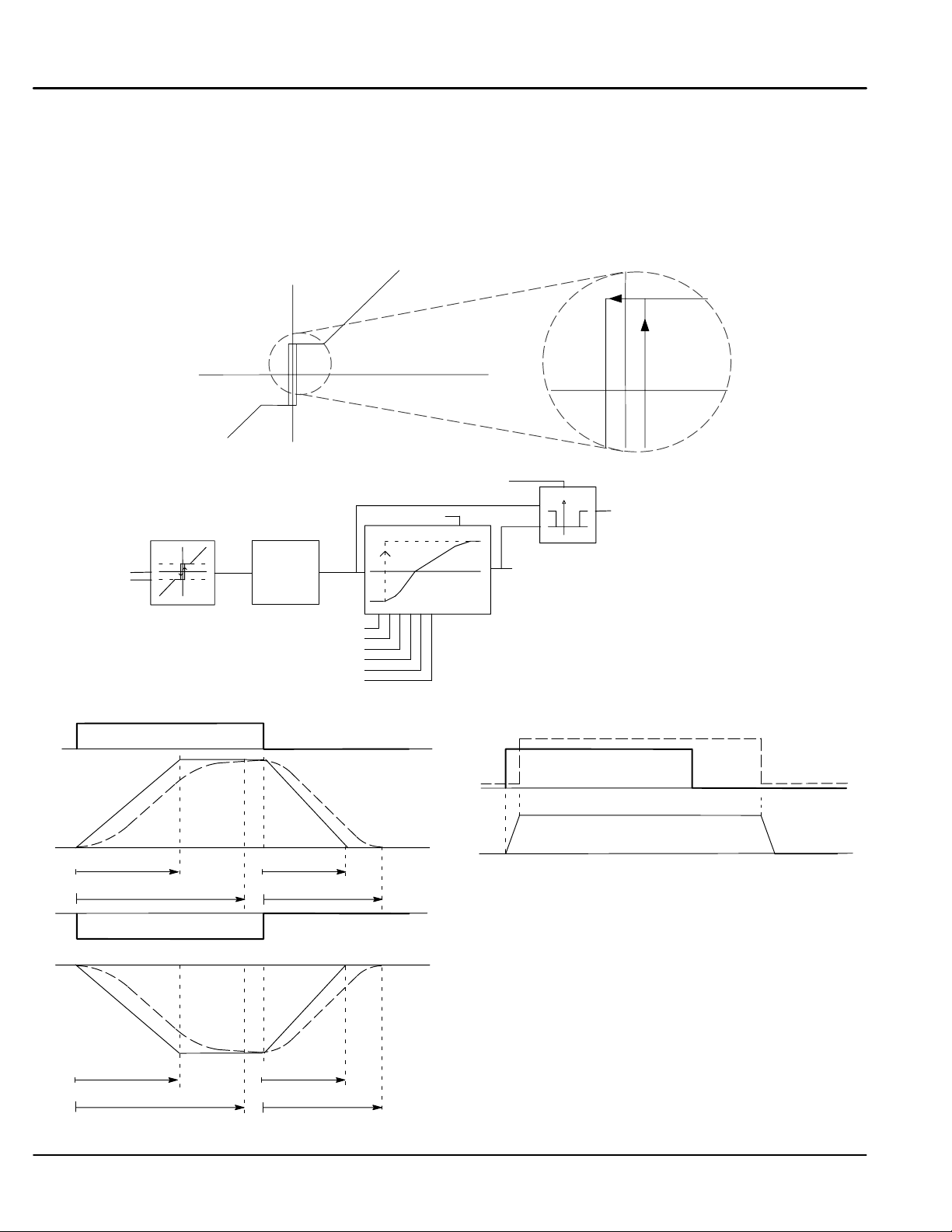
Ramps Continued
Parameter Descriptions
Reset Value
This value is loaded into the output when Ramp Reset is true, or at power–up. To catch a spinning
load smoothly (‘bumpless transfer’), connect Speed Feedback [62] (source) to Reset Value [422]
(destination).
MIN. Speed
The minimum speed clamp is fully bi–directional and operates with a 0.5% hysteresis. This clamp
operates on the input to the ramp and it can therefore be overrridden by the Reset Value (as far as
the ramp output is concerned).
Minimum Speed
Output
Range: –300.00 to 300.00 %
Range: 0.00 to 100.00 %
Functional Description
Ramp Input [5]
Min Speed [126]
Acceleration / Deceleration Rates
RAMP INPUT (+ 100%)
0%
RAMP OUTPUT
0%
0%
0%
+100%
Ramp Accel Time
(S Ramp 0%)
Actual Accel Time
with S Ramp
RAMP INPUT (-100%)
S/P O/P
Jog/Slack
Ramp Decel Time [3]
Ramp Accel Time [2]
Ramp Hold [118]
Auto Reset [287]
External Reset [288]
Reset Value [422]
RAMP DECEL TIME
(S RAMP 0%)
Actual Decel Time
with S Ramp
Input
Ramping Threshold [286]
% S Ramp [266]
Input Output
0
S" Ramp
t
0%
t
0%
t
t
-0.5
0
0.5
Input
Output
t
Ramp Hold
Off
Ramp Output [293]
RAMP HOLD ON
RAMP OUTPUT
1
0
Ramp Input
Ramping [113]
Off
t
Ramp operation occurs when a ramp input is present. When
Digital Input 2 is ON, Ramp Hold stops the ramp output from
changing. Even when the ramp input signal is removed,
Ramp Hold keeps the ramp output from changing. Once
Ramp Hold is off, the ramp resumes.
t
RAMP OUTPUT
-100%
Ramp Accel Time
(S Ramp 0%)
Actual Accel Time
with S Ramp
RAMP DECEL TIME
(S RAMP 0%)
Actual Decel Time
with S Ramp
6-36 Programming MN792
Page 93

Ramps Continued
Minimum Speed
100%
X%
Ramp Input
0%
100%
X%
Ramp Output
Y%
0%
t
0
t
0
Drive Enabled
Ramp Input
This figure shows the effect of setting MIN. Speed
above 0.00%. When the drive is enabled, the ramp
output cannot decrease below the MIN. Speed value.
Note the ramp rates are used when changing the
t
output from minimum speed to zero speed. Notice also
that in this example the ramp output only increases to
X% since the ramp input signal is limited to X%.
t
Auto Reset
100%
X%
Ramp Input
0%
100%
X%
Ramp Output
0%
External Reset
100%
X%
Ramp Input
0%
100%
X%
Ramp Output
Y%
0%
Drive Enabled
t
0
t
0
Drive Enabled
t
0
t
0
Ramp Input
Ramp Input
With Auto Reset enabled, the ramp output resets to
reset value each time the drive is enabled. In this
example, reset value is 0.00%. It does not reset if the
drive is disabled.
t
t
The ramp input is set to X% at time t0 . The ramp
output will increase at the ramp rate. While external
reset is enabled, the ramp output resets to reset value.
When external reset is disabled, the ramp output
t
t
continues to follow input signal.
Programming 6-37MN792
Page 94

Setpoint Sum 1
Setpoint Sum 1 allows the summing and scaling of three analog inputs to produce SPT. Sum Output [294].
Note: This block is ignored by the drive unless [294] is connected to a nonzero destination tag.
Input 0 and Input 1 have individual ratio and divider scalers, and signs. Input 1 has an additional deadband
function set by Deadband Width. When the input is within the deadband, the output clamps to zero to ignore any
noise. This parameter is useful when digital setpoints are used (for example from a 5703, serial
communications, or the Raise Lower function block). The inputs have symmetrical limits set by Limit. Input 2 has
no scaling or limits. The output after Input 0, Input 1, and Input 2 are summed is also clamped by Limit before
producing SPT. Sum Output.
1 SETUP PARAMETERS
2 SETPOINT SUM 1
Ratio 1
Ratio 0
Sign 1
Sign 0
Divider 1
Divider 0
Deadband Width
Limit
Input 2
Input 1
Input 0
Analog
Input 1
A2
Setpoint Sum 1
Tag Parameter
[292] Sign 0 Positive
[208] Ratio 0 1.0000
[309] Input 0 0.00%
[420] Divider 0 1.0000
[423] Input 2 0.00%
[6] Ratio 1 1.0000
[100] Input 1 0.00%
[131] Deadband Width 0.00%
[419] Divider 1 1.0000
[8] Sign 1 Positive
[375] Limit 105.00%
[294] SPT Sum 1 Dest 390
Factory Setting
A/B
A/B
+
-
+
-
Parameter Descriptions
SPT. Sum 1 Destination [294] (Set in Configure I/O::Block Diagram Parameters)
Refer to the diagnostics function block description.
SPT. Sum Output [86] (Read in Diagnostics Parameters)
Refer to the diagnostics function block description.
Ratio 1
Analog input 1 scaling.
Ratio 0
Input 0 scaling.
Sign 1
Analog input 1 polarity.
Sign 0
Input 0 polarity.
Divider 1
Analog input 1 scaling. Dividing by 0 (zero) results in a zero output.
Divider 0
Input 0 scaling. Dividing by 0 (zero) results in a zero output.
Deadband Width
Analog input 1 deadband width. When Input 1 is within the deadband, the output clamps to zero to
ignore any noise.
LIMIT
The Setpoint Sum 1 programmable limit is symmetrical and has the range of 0.00% to 200.00%.
The limit is applied both to the intermediate results of the ratio calculation and the total ouput.
INPUT 2
Input 2 value. The factory settings do not connect this input to any analog input.
INPUT 1
Input 1 value. The factory settings connects this input to Analog Input 1 (A2).
INPUT 0
Input 0 value. The factory settings do not connect this input to any analog input.
SPT Sum
+
+
+
Destination
[294]
[86]
Diagnostic
Connection
Range: 0 to 549
Range: R/O
Range: –3.0000 to 3.0000
Range: –3.0000 to 3.0000
Range: 0 : Negative
1 : Positive
Range: 0 : Negative
1 : Positive
Range: –3.0000 to 3.0000
Range: –3.0000 to 3.0000
Range: 0.00 to 100.00 % (h)
Range: 0 : False
1 : True
Range: –200.00 to 200.00 %
Range: –200.00 to 200.00 %
Range: –200.00 to 200.00 %
6-38 Programming MN792
Page 95

Speed Loop
Speed loop selects the speed feedback source and tunes the speed loop PI to produce a current demand. The
parameters are set in several menus, some parameters can be set in multiple menus. Speed FBK Select
determines the source of the speed feedback signal. The default, Arm Volts FBK, uses internal circuitry to derive
speed feedback. The other selections require external devices to provide the feedback signal. Speed Demand is
summed algebraically with Speed Feedback to yield Speed Error. When the drive is enabled, Speed Error is
controlled by the PI loop. Proportional and integral values are set in the Advanced::Adaption block. The resulting
current demand signal is sent to the Current Loop block and to the Advanced::Zero SPD. Quench block.
1 SETUP PARAMETERS
2 SPEED LOOP
Speed PROP Gain
Speed INT Time
INT Defeat
Encoder Sign
Speed FBK Select
Speed FBK Filter
1 CONFIGURE DRIVE
Speed FBK Select
Encoder Sign
Speed INT Time
Speed PROP Gain
Speed Loop
[119]
Analog
Input 2
Tag# Parameter Factory Setting
[7] Ratio 2 (A3) 1.0000 Sec
A3
[9] Sign 2 (A3) Positive
[290] Setpoint 2 0.00%
[41] Setpoint 4 1.0000 Sec
[289] Setpoint 1 SPT Sum Out
[291] Setpoint 3 Ramp Out
[357] MAX Demand 105.00%
[358] MIN Demand -105.00%
[13] INT Time Constant 0.500 Sec
[14] PROP Gain 10.00
Advanced
Adaption
Tag# Parameter Factory Setting
[270] SPD BRK2 (High) 5.00%
[269] SPD BRK2 (Low) 1.00%
[268] Mode 0
[271] PROP Gain 5.00
[272] INT Time Constant 0.500 Sec
1 SETUP PARAMETERS
2 SPEED LOOP
3 SETPOINTS
Setpoint 1
Sign 2 (A3)
Ratio 2 (A3)
Setpoint 3
Setpoint 4
MAX Demand
MIN Demand
I DMD Isolate (from Current Loop)
1 SETUP PARAMETERS
2 SPEED LOOP
3 ADVANCED
4 ADAPTION
Mode
Speed BRK1 (Low)
Speed BRK2 (High)
PROP Gain
+
+
+
+
P
I
1 SETUP PARAMETERS
2 SPEED LOOP
3 ADVANCED
I Gain in Ramp
POS Loop P Gain
+ / -
Zero SPD Quench
Tag# Parameter Factory Setting
[284] Zero SPD Level 0.50%
[285] Zero IAD Level 1.50%
1 SETUP PARAMETERS
2 SPEED LOOP
3 ADVANCED
4 ZERO SPD QUENCH
Zero SPD Level
Zero IAD Level
Speed Setpoint
To IDMD
Isolate Switch
(To Current Loop)
Diagnostic
[63]
Connection
Armature SCR
Firing Quench
[202] INT Defeat Off
[89] Speed Demand
Speed Feedback Select
[47] Speed FBK Select
Armature Volts
Analog Tach
Encoder
[49] Encoder Sign (+/-)
Zero SPD Offset
From Calibration Board
+ / -
+
PI
-
+
-
Note: Encoder analog feedback selection uses analog Tach feedback for the proportional
term of the speed loop PI and encoder feedback for the Integral term. This feedback
selection requires that the motor have an analog Tach/Encoder installed. This
selection cannot be used with the switchable Tachogenerator board is installed.
Unfiltered Speed Error
Unfiltered Speed Feedback
Current Demand
To Current
[356]
Loop
Diagnostic
[64]
Connection
Diagnostic
[297]
Connection
Diagnostic
[62]
Connection
Diagnostic
[207]
Connection
Programming 6-39MN792
Page 96

Speed Loop Continued
Parameter Descriptions
Speed Loop Output SPD Loop Output (Read in Diagnostics Parameters)
Output from Speed Loop PI.
Speed Feedback (Read in Diagnostics Parameters)
The speed feedback value from the source chosen by SPEED FBK SEL.
Speed Setpoint (Read in Diagnostics Parameters)
Speed loop total setpoint including the ramp output before the ramp–to–zero function.
Speed Error (Read in Diagnostics Parameters)
Speed loop error.
Speed PROP. Gain (Can be set in Speed Loop or Configure Drive.)
Speed loop Pi proportional gain adjustment.
Speed INT. Time (Can be set in Speed Loop or Configure Drive.)
Speed loop PI integral gain adjustment.
INT. DEFEAT
Inhibits the integral part of the speed loop PI to give proportional control only.
Encoder Sign (Can be set in Speed Loop or Configure Drive.)
Since the encoder feedback cannot be reversed electrically, the signal polarity can be reversed by
the control software.
Speed FBK Select (Can be set in Speed Loop or Configure Drive.)
Four options are available:
0 : ARM Volts FBK
1 : Analog TACH
2 : Encoder
3 : Encoder/Analog
Setpoint 1
Speed Setpoint 1.
Sign 2 (A3)
Speed Setpoint 2 Sign.
Parameter Descriptions
Ratio 2 (A3)
Speed Setpoint 2 Ratio.
Setpoint 2 (A3) This is a fixed (non–configurable) input.
This setpoint is scanned synchronously with the current loop .
Setpoint 3
Speed Setpoint 3.
Setpoint 4
Speed Setpoint 4.
MAX Demand
Sets the maximum input to the speed loop. It is clamped at 105% to allow for overshoot in the
external loops.
MIN Demand
Sets the minimum input to the speed loop.
I Gain in Ramp Range:
Range: xxx.xx %
Range: xxx.xx %
Range: xxx.xx %
Range: xxx.xx %
Range: 0.00 to 200.00
Range: 0.001 to 30.000
Range: 0 : Off
Range: 0 : Negative
Range: 0 to 3
Range: –105.00 to 105.00 %
Range: 0 : Negative
Range: –3.0000 to 3.0000
Range: xxx.xx %
Range: –105.00 to 105.00 %
Range: –105.00 to 105.00 %
Range: 0.00 to 105.00 %
Range: –105.00 to 105.00 %
Seconds
1 : On
1 : Positive
1 : Positive
POS Loop P Gain Range:
Zero SPD Level Range:
Zero IAD Level Range:
Functional Description
Speed Loop PI Output – The PI output is available for connection using tag no. 356. This point is before the I Limit clamps
and the summing of the additional current demand. This tag is not visible at the keypad.
Speed Loop PI with Current Demand Isolate – The speed loop output is still valid (active) with the I DMD. Isolate parameter
enabled.
1. The speed loop is reset by unquenching the speed loop/current loop.
2. I DMD. ISOLATE is overridden by Program Stop (B8) or Normal Stop (C3).
3. The speed loop PI holds the integral term as soon as the PI output reaches current limit. This is true even in Current
Demand Isolate mode where it may interfere depending on the way the speed PI is used. At the present time. this feature
cannot be suppressed.
105% Speed Demands – The speed demand clamping allows the speed setpoint to reach 105%. This applies only to the
final summing junction immediately before the speed loop and also to the Setpoint Sum 1 output. Individual speed setpoints
are still clamped to 100%.
6-40 Programming MN792
Page 97

Speed Loop Continued
Advanced This function block is shown in Speed Loop
Adaption Adjusts speed loop gain scheduling.
Zero SPD Quench Similar to Standstill logic (i.e. keeps the contactor in but motor current drops to zero) except
the speed loop stays enabled and will cause the current loop to unquench very quickly.
1 SETUP PARAMETERS
1 SETUP PARAMETERS
2 SPEED LOOP
3 ADVANCED
4 ADAPTION
Mode
Speed BRK1 (Low)
Speed BRK2 (High)
PROP Gain
SPD INT Time
2 SPEED LOOP
3 ADVANCED
I Gain in Ramp
POS Loop P Gain
1 SETUP PARAMETERS
2 SPEED LOOP
3 ADVANCED
4 ZERO SPD QUENCH
Zero SPD Level
Zero IAD Level
Parameter Descriptions
Mode
0 – Disabled
1 – Speed Feedback Dependent
2 – Speed Error Dependent
3 – Current Demand Dependent
SPD BRK 1 (Low)
If Mode = 1 Then BRK–points correspond to speed feedback.
If Mode = 2 Then BRK–points correspond to speed error.
If Mode = 3 Then BRK–points correspond to current demand.
SPD BRK 2 (High)
Above SPD BRK 2 (HIGH) the normal gains (as per main menu above) prevail. Between the two
breakpoints, a linear variation of the gains is implemented.
PROP. Gain
Prop gain used below SPD BRK 1 (LOW)
SPD INT Time
Integral time constant used below SPD BRK 1 (LOW)
I Gain IN Ramp
While the Ramping flag (Tag [113]) is true the integral gain is scaled by I GAIN IN RAMP. This can
be used to help prevent integral windup while the drive is ramping (particularly with high inertia
loads).
POS. LOOP P GAIN
Reserved parameter.
Zero SPD. Level
Sets the threshold of speed feedback below which Zero Speed Quench is active.
Zero IAD Level
Sets the threshold of current feedback below which Zero Speed Quench is active.
Range: 0 to 3
Range: 0.00 to 100.00 %
Range: 0.00 to 100.00 %
Range: 0.00 to 200.00
Range: 0.001 to 30.000
Seconds
Range: 0.0000 to 2.0000
Range: –200.00 to 200.00 %
Range: 0.00 to 200.00 %
Range: 0.00 to 200.00 %
Programming 6-41MN792
Page 98

Standstill Standstill logic is used to inhibit rotation during Zero Speed demand. If the drive is below the zero speed
threshold [12] and Standstill Logic [11] is enabled, the speed and current loops are quenched to prevent shaft
oscillation around zero speed. Standstill Logic is useful in maintaining absolute zero speed but can cause
problems in web handling applications using tension feedback. At zero speed, the SCR’s turn off allowing web
tension to pull the driven roll in reverse. When the drive no longer senses zero speed, the SCR’s turn on
causing forward rotation and regulate tension. An oscillation condition can result as the drive SCR’s turn on and
off trying to maintain a fixed position. A “not at standstill” signal is sent to the drive enable logic.
When Speed Feedback is less than Zero Threshold, the At Zero Speed output is On. At Zero Setpoint is on
when Speed Setpoint is less than Zero Threshold. When both At Zero Speed and At Zero Setpoint are on, At
Standstill is on to indicate the motor has stopped.
When Standstill Logic is enabled, the SCR firing circuits are disabled, the main contactor remains energized and
the Run Led stays on when the drive is at standstill. The drive remains in this state until standstill drops out (the
speed setpoint or speed feedback increase above the zero threshold value).
1 SETUP PARAMETERS
2 STANDSTILL
Standstill Logic
Zero Threshold
Source Tag
Speed Feedback
from [62] Speed Loop
Speed Setpoint
from [63] Speed Loop
89
Parameter Descriptions
AT Zero Setpoint (Read in Diagnostics Parameters)
At zero speed demand.
AT Zero Speed (Read in Diagnostics Parameters)
At zero speed feedback.
AT Standstill (Read in Diagnostics Parameters)
At zero speed and zero setpoint.
Source Tag (Zero Setpoint)
Reserved parameter.
Standstill Logic
If true, the control is quenched (although the contactor remains in) when the speed feedback and
speed setpoint values are less than zero threshold.
Zero Threshold
Threshold level which defines zero setpoint and zero speed diagnostic outputs and also controls the
zero speed relay output.
Functional Description
Standstill logic inhibits the controller at zero setpoint and zero speed, i.e. at standstill. The main contactor
remains in and the Run LED remains on.
Disabled
Standstill Logic
Speed Feedback
0%
Speed Setpoint
2%
0%
-2%
Zero Treshold
Standstill
Tag# Parameter Factory Setting
[306] Source Tag 89
[12] Zero Threshold 2.00%
[11] Standstill Logic Disabled
Enabled
Speed Feedback
Curve depends on load characteristics
At Zero Speed
At Zero Setpoint
At Standstill
t
t
Diagnostic
78
Connection
Digital Output 1 (B5)97[77]
[78]
[79]
Not At Standstill"
To Enable circuit
Range: 0 : False
1 : True
Range: 0 : False
1 : True
Range: 0 : False
1 : True
Range: 0 to 549
Range: 0 : Disabled
1 : Enabled
Range: 0.00 to 100.00 %
Enabled
t
Drive Enable
0%
Enabled
Disabled
6-42 Programming MN792
Page 99

Stop Rates
Sets the stop method parameters for the control. A normal stop occurs when the Run signal is removed from
terminal C3. It ramps the speed demand to zero at a rate set by Stop Time. Series 29 Non–regenerative drives
will stop no faster than the coast stop rate. Series 30 Regenerative drives use Stop Time to set the duration of
the stop. After the stop, the contactor de–energizes and the drive disables. The Stop Limit timer starts when C3
goes to zero volts. If the drive speed has not reached Stop Zero Speed within the Stop Limit time, the contactor
de–energizes and the drive disables.
During normal stops, Contactor Delay delays de–energizing the contactor after the motor reaches zero speed.
When Stop Zero Speed is set greater than 0.25%, the drive disables during the contactor delay. Below 0.25%,
the drive disables after the contactor delay. This is useful when using the jog function to prevent multiple
operations of the contactor. Contactor Delay is overridden when terminal C4 is at zero volts.
Program Stop provides a controlled fast stop using regenerative drives. The stop time is set by Program Stop
Time. The timer starts when terminal B8 goes to zero volts. When the drive reaches Stop Zero Speed, the
contactor de–energizes and the drive disables. Program Stop Limit sets the maximum time the program stop
can take before the contactor de–energizes and the drive disables.
Prog Stop I Lim sets the current limit (current loop) during a program stop. Other current limits can override it.
1 SETUP PARAMETERS
2 STOP RATES
Stop Time
Stop Limit
Contactor Delay
PROG Stop Time
PROG Stop Limit
PROG Stop I LIM
Stop Zero Speed
Program Stop is true when terminal
B8 is Low (Status LED Off).
Speed Setpoint
from [62] Speed Loop
Drive
Start
Speed Feedback
from [63] Speed Loop
Program
Stop
Stop Rates
Tag# Parameter Factory Setting
[91] PROG Stop I Limit 100.00%
[27] Stop Time 10.0 Sec
[26] PROG Stop Time 0.1 Sec
[217] Stop Limit 60.0 Sec
[216] PROG Stop Limit 60.0 Sec
[82]
[29] Stop Zero Speed 2.00%
[302] Contactor Delay 1.0 Sec
B8
t
Parameter Descriptions
Speed Demand (Read in Diagnostics Parameters)
Speed loop total setpoint after the ramp–to–zero block.
Program Stop (Read in Diagnostics Parameters)
State of Program Stop (Terminal B8). When B8 is at 24V, then Program Stop is false and the
Program Stop front panel LED is also on.
Stop Time
Time to reach zero speed from 100% set speed in normal stop mode (C3 Off).
Stop Limit
Delay time limit to allow normal stop action (regenerative breaking) to achieve zero speed before
drive quench and coast stop. The timer is triggered by Start command (C3) going low.
Contactor Delay
This defines the time between the drive reaching Stop Zero Speed (Tag [29]) and the contactor
being opened. This is particularly useful during the jog cycle to prevent multiple operations of the
main contactor.
If Stop Zero Speed is ≥ 0.25%, the drive will be quenched during the contactor delay time. The
Contactor delay is overridden by Enable (C4).
Maintain zero speed during contactor delay.
If Stop Zero Speed is < 0.25%, the drive is not quenched until after the Contactor Delay time.
PROG Stop Time
Time to reach zero speed from 100% set speed in program stop mode (B8 OFF).
PROG Stop Limit
Delay time limit to allow program stop action (regenerative breaking) to achieve zero speed before
drive quench and coast stop. The timer is triggered by program stop command (B8) going low.
PROG Stop I LIM
Main current limit level in program stop mode assuming current limit not overridden by I Profile or
Inverse Time limits.
Stop Zero Speed
Zero speed level in program stop and normal stop modes at which the contactor delay timer starts
timing out. At the end of this delay the contactor is de–energized.
PROG Stop I Limit
To Current Loop
Speed
[89]
Demand
t
t
To Coast
Stop Logic
Range: xxx.xx %
Range: 0 : False
1 : True
Range: 0.1 to 600.0
Seconds
Range: 0.0 to 600.0
Seconds
Range: 0.1 to 600.0
Seconds
Range: 0.1 to 600.0
Seconds
Range: 0.0 to 600.0
Seconds
Range:
Range: 0.00 to 100.00 %
Programming 6-43MN792
Page 100

Stop Rates Continued
Functional Description
Stop Hierarchy
Note: The Control’s reaction to commands is defined by a state machine. This determines which commands
Normal Stop Sequence
Stop Zero Speed settings less than 0.25% allow the control to remain enabled for the Contactor Delay Time
after reaching Stop Zero Speed. This is useful for Jog applications.
100
Coast Stop – Terminal B9
• Disables the drive and opens the contactor using the pilot output
Enable – Terminal C4
• Suspends and resets the control loops
Program Stop – Terminal B8
• Independent ramp time
• Stop Timer
• Independent current limit may be greater than normal current limit
• Independent zero speed
Normal Run/Stop – Terminal C3
• Independent ramp time
• Contactor Delay
provide the demanded action, and in which sequence. Consequently, Coast Stop and Program Stop
must be false (the Control is not in Coast or Program mode), before a Run signal is applied. Otherwise
the control assumes a stop mode and remains disabled.
Start / Run (C3)
Speed Setpoint %
Speed Demand %
Speed Feedback %
Drive Enable
0
100
0
100
0
0
Stop Zero Speed 2.00%
2
Enabled
Stop Time
10.0 Seconds
Actual stop rate depends on load inertia, motor horse power and
overload capacity of drive (motor + control)
Control is disabled below
Stop Zero Speed if set>0.25%
Control remains enabled for the Contactor Delay if
Stop Zero Speed <0.25%
Disabled
6-44 Programming MN792
 Loading...