

Page 1

Series 35D
Inverter Control
Installation & Operating Manual
8/02
MN735
Page 2

Table of Contents
Section 1
Quick Start 1–1. . . . . . . . . . . . . . . . . . . . . . . . . . . . . . . . . . . . . . . . . . . . . . . . . . . . . . . . . . .
Section 2
General Information 2–1. . . . . . . . . . . . . . . . . . . . . . . . . . . . . . . . . . . . . . . . . . . . . . . . . . .
CE Compliance 2–1. . . . . . . . . . . . . . . . . . . . . . . . . . . . . . . . . . . . . . . . . . . . . . . . . . .
Limited Warranty 2–1. . . . . . . . . . . . . . . . . . . . . . . . . . . . . . . . . . . . . . . . . . . . . . . . . .
Product Notice 2–2. . . . . . . . . . . . . . . . . . . . . . . . . . . . . . . . . . . . . . . . . . . . . . . . . . . .
Safety Notice 2–2. . . . . . . . . . . . . . . . . . . . . . . . . . . . . . . . . . . . . . . . . . . . . . . . . . . . .
Section 3
Receiving & Installation 3–1. . . . . . . . . . . . . . . . . . . . . . . . . . . . . . . . . . . . . . . . . . . . . . . .
Receiving & Inspection 3–1. . . . . . . . . . . . . . . . . . . . . . . . . . . . . . . . . . . . . . . . . . . . .
Location and Mounting 3–1. . . . . . . . . . . . . . . . . . . . . . . . . . . . . . . . . . . . . . . . . . . . .
Cover Removal 3–3. . . . . . . . . . . . . . . . . . . . . . . . . . . . . . . . . . . . . . . . . . . . . . . . . . . .
Power Conditioning 3–3. . . . . . . . . . . . . . . . . . . . . . . . . . . . . . . . . . . . . . . . . . . . . . . .
System Grounding 3–3. . . . . . . . . . . . . . . . . . . . . . . . . . . . . . . . . . . . . . . . . . . .
Line Impedance 3–4. . . . . . . . . . . . . . . . . . . . . . . . . . . . . . . . . . . . . . . . . . . . . .
Line Reactors 3–4. . . . . . . . . . . . . . . . . . . . . . . . . . . . . . . . . . . . . . . . . . . . . . . .
Load Reactors 3–4. . . . . . . . . . . . . . . . . . . . . . . . . . . . . . . . . . . . . . . . . . . . . . . .
Power Disconnect 3–4. . . . . . . . . . . . . . . . . . . . . . . . . . . . . . . . . . . . . . . . . . . .
Protective Devices 3–4. . . . . . . . . . . . . . . . . . . . . . . . . . . . . . . . . . . . . . . . . . . .
Reduced Input Voltage Derating 3–4. . . . . . . . . . . . . . . . . . . . . . . . . . . . . . . .
Electrical Installation 3–5. . . . . . . . . . . . . . . . . . . . . . . . . . . . . . . . . . . . . . . . . . . . . . .
Clamp Terminals 3–5. . . . . . . . . . . . . . . . . . . . . . . . . . . . . . . . . . . . . . . . . . . . . .
Power Connections 3–6. . . . . . . . . . . . . . . . . . . . . . . . . . . . . . . . . . . . . . . . . . .
Thermistor Connections 3–9. . . . . . . . . . . . . . . . . . . . . . . . . . . . . . . . . . . . . . .
Signal Connections 3–10. . . . . . . . . . . . . . . . . . . . . . . . . . . . . . . . . . . . . . . . . . .
External Brake Resistor 3–11. . . . . . . . . . . . . . . . . . . . . . . . . . . . . . . . . . . . . . . .
User Relay 3–11. . . . . . . . . . . . . . . . . . . . . . . . . . . . . . . . . . . . . . . . . . . . . . . . . . .
Applications/Modes 3–11. . . . . . . . . . . . . . . . . . . . . . . . . . . . . . . . . . . . . . . . . . . . . . . .
How to Load an Application 3–11. . . . . . . . . . . . . . . . . . . . . . . . . . . . . . . . . . . .
1 – Keypad Mode 3–12. . . . . . . . . . . . . . . . . . . . . . . . . . . . . . . . . . . . . . . . . . . . .
2 – Standard Run 3 Wire Mode 3–13. . . . . . . . . . . . . . . . . . . . . . . . . . . . . . . . .
3 – 3 Speed 2 Wire Mode 3–14. . . . . . . . . . . . . . . . . . . . . . . . . . . . . . . . . . . . . .
4 – EPOT 3 Wire Mode 3–15. . . . . . . . . . . . . . . . . . . . . . . . . . . . . . . . . . . . . . . .
5 – EPOT 2 Wire Mode 3–16. . . . . . . . . . . . . . . . . . . . . . . . . . . . . . . . . . . . . . . .
6 – PID 2 Wire Mode 3–17. . . . . . . . . . . . . . . . . . . . . . . . . . . . . . . . . . . . . . . . . .
Table of Contents iMN735
Page 3

Section 4
Start–Up and Operation 4–1. . . . . . . . . . . . . . . . . . . . . . . . . . . . . . . . . . . . . . . . . . . . . . . .
Keypad Description 4–1. . . . . . . . . . . . . . . . . . . . . . . . . . . . . . . . . . . . . . . . . . . . . . . .
Display 4–2. . . . . . . . . . . . . . . . . . . . . . . . . . . . . . . . . . . . . . . . . . . . . . . . . . . . . .
Diagnostics Menu 4–2. . . . . . . . . . . . . . . . . . . . . . . . . . . . . . . . . . . . . . . . . . . . .
Menu System 4–3. . . . . . . . . . . . . . . . . . . . . . . . . . . . . . . . . . . . . . . . . . . . . . . . . . . . .
Power Up 4–4. . . . . . . . . . . . . . . . . . . . . . . . . . . . . . . . . . . . . . . . . . . . . . . . . . . . . . . . .
How to Change a Parameter Value 4–4. . . . . . . . . . . . . . . . . . . . . . . . . . . . . . . . . . .
Special Menu Features 4–4. . . . . . . . . . . . . . . . . . . . . . . . . . . . . . . . . . . . . . . . . . . . .
Parameter Definitions 4–6. . . . . . . . . . . . . . . . . . . . . . . . . . . . . . . . . . . . . . . . . . . . . .
PI Terms 4–12. . . . . . . . . . . . . . . . . . . . . . . . . . . . . . . . . . . . . . . . . . . . . . . . . . . . .
Product Related Parameter Values 4–13. . . . . . . . . . . . . . . . . . . . . . . . . . . . . .
Routine Maintenance 4–14. . . . . . . . . . . . . . . . . . . . . . . . . . . . . . . . . . . . . . . . . . . . . . .
Saving Your Application Data 4–14. . . . . . . . . . . . . . . . . . . . . . . . . . . . . . . . . . . . . . . .
Disposal 4–14. . . . . . . . . . . . . . . . . . . . . . . . . . . . . . . . . . . . . . . . . . . . . . . . . . . . . . . . . .
Section 5
Troubleshooting 5–1. . . . . . . . . . . . . . . . . . . . . . . . . . . . . . . . . . . . . . . . . . . . . . . . . . . . . .
Trips 5–1. . . . . . . . . . . . . . . . . . . . . . . . . . . . . . . . . . . . . . . . . . . . . . . . . . . . . . . . . . . . .
General Failures 5–2. . . . . . . . . . . . . . . . . . . . . . . . . . . . . . . . . . . . . . . . . . . . . . . . . . .
Section 6
Specifications & Product Data 6–1. . . . . . . . . . . . . . . . . . . . . . . . . . . . . . . . . . . . . . . . . .
General Specifications 6–1. . . . . . . . . . . . . . . . . . . . . . . . . . . . . . . . . . . . . . . . . . . . .
Control Specifications 6–2. . . . . . . . . . . . . . . . . . . . . . . . . . . . . . . . . . . . . . . . .
Keypad Display 6–2. . . . . . . . . . . . . . . . . . . . . . . . . . . . . . . . . . . . . . . . . . . . . . .
Analog Inputs 6–2. . . . . . . . . . . . . . . . . . . . . . . . . . . . . . . . . . . . . . . . . . . . . . . .
Analog Outputs 6–3. . . . . . . . . . . . . . . . . . . . . . . . . . . . . . . . . . . . . . . . . . . . . . .
Digital Inputs 6–3. . . . . . . . . . . . . . . . . . . . . . . . . . . . . . . . . . . . . . . . . . . . . . . . .
Digital Outputs 6–3. . . . . . . . . . . . . . . . . . . . . . . . . . . . . . . . . . . . . . . . . . . . . . .
Relay Output 6–3. . . . . . . . . . . . . . . . . . . . . . . . . . . . . . . . . . . . . . . . . . . . . . . . .
Ratings 6–3. . . . . . . . . . . . . . . . . . . . . . . . . . . . . . . . . . . . . . . . . . . . . . . . . . . . . . . . . . .
Dimensions 6–4. . . . . . . . . . . . . . . . . . . . . . . . . . . . . . . . . . . . . . . . . . . . . . . . . . . . . . .
Appendix A
Dynamic Brake A–1. . . . . . . . . . . . . . . . . . . . . . . . . . . . . . . . . . . . . . . . . . . . . . . . . . . . . . . .
230VAC 1 & 3 Phase Controls A–1. . . . . . . . . . . . . . . . . . . . . . . . . . . . . . . . . . . . . . .
460VAC 3 Phase Controls A–1. . . . . . . . . . . . . . . . . . . . . . . . . . . . . . . . . . . . . . . . . .
Brake Calculations A–1. . . . . . . . . . . . . . . . . . . . . . . . . . . . . . . . . . . . . . . . . . . . . . . . .
RGA and RGJ Assemblies A–1. . . . . . . . . . . . . . . . . . . . . . . . . . . . . . . . . . . . . . . . . .
Appendix B
CE Guidelines B–1. . . . . . . . . . . . . . . . . . . . . . . . . . . . . . . . . . . . . . . . . . . . . . . . . . . . . . . . .
ii Table of Contents MN735
Page 4
Section 1
Quick Start
The basic steps for connection and setup are provided in this section.
Detailed descriptions of each step and parameter settings are provided
later in this manual. Be sure to comply with all applicable codes when
installing this control.
Minimum Connection Requirement
Power and Motor Connections
Figures 1-1and 1-2 show the minimum connections required at the power
connector.
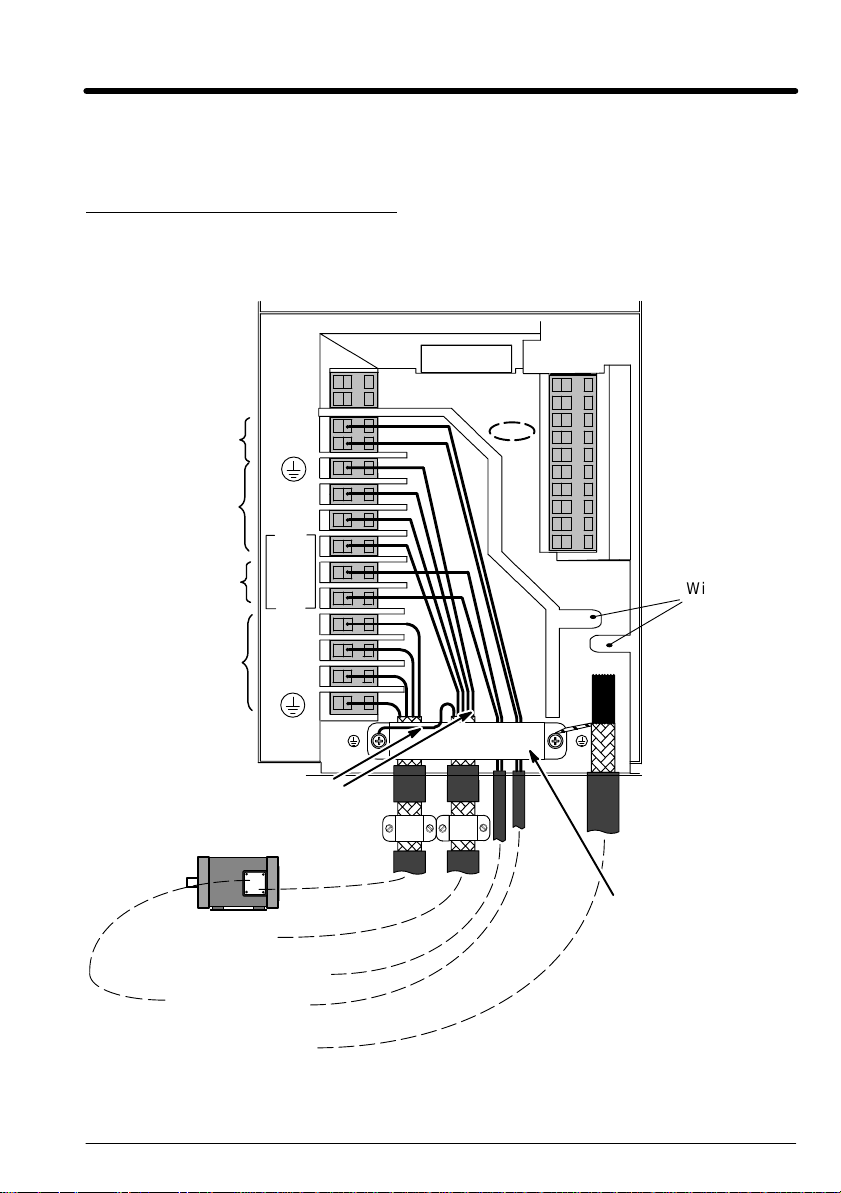
Figure 1-1 Power Connections
Size 2 Shown
s Refer to Section 3 for cover removal procedure.
TH1A and TH1B must
be jumpered if
thermistor is not used
AC Line
Connections
Dynamic Brake
Connections
Motor
Connections
L1, L2, L3, GND
RL1A
RL1B
TH1A
TH1B
L1
L2/N
L3
DC+
DBR
M1/U
M2/V
M3/W
Use 2 Ground
Wires
Motor Cable
Mains Supply
Cable
Use a cable tie
in this area for
control wires.
10
9
8
7
6
5
4
3
2
1
Wire Retainer
(Channel)
Grounded
Cable Clamp
Dynamic Brake Cable
Thermistor Cable
Control Signal Cable
Quick Start 1–1MN735
Page 5
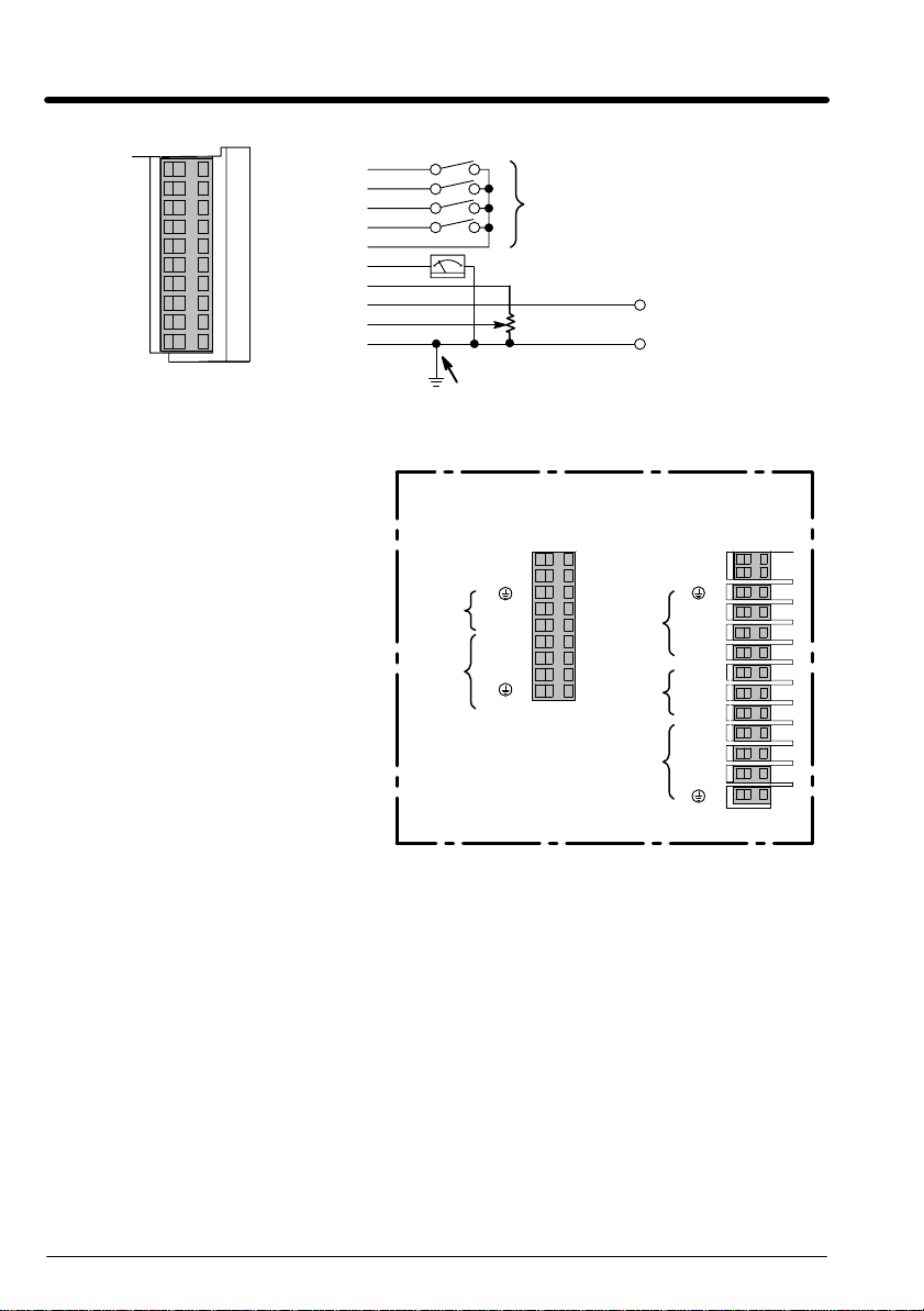
Figure 1-2 Power Connections Continued
10
DIN4/DOUT2
9
8
7
6
5
4
3
2
1
DIN3
DIN2
DIN1
+24V
AOUT1
+10V Ref
AIN2
AIN1
0V
Feedback
Setpoint
See Applications/Modes
10k Speed
Setpoint
Connect 0V to PE (protective earth ground)
for single control installations only. If multiple
controls are used, connect 0V terminals
together and ground to PE at one point only.
Size 1 and 3 Terminal Strips
Size 1
TH1A
TH1B
AC
Line
Motor
L1
L2/N
M1/U
M2/V
M3/W
1φ 230VAC
AC Line
Dynamic
Brake
Motor
Volts or
0–20mA Input
Size 3
TH1A
TH1B
L1
L2
L3
DC+
DBR
DC–
M1/U
M2/V
M3/W
3φ 460VAC
Jumpers and Switches None
Control Terminal Connections See Table 1–2.
Local Mode
No connections are required.
Remote Mode
Control terminals 1 to 10 can be connected as shown in the application
modes described in Section 3 of this manual.
1–2 Quick Start MN735
Page 6

Table 1–1 Power Connection Descriptions
idly t
2000Ω
this t
o
Range
above
380/460VAC±10%
with respect to L2, L3.
380/460VAC±10%
with respect to L1, L3.
emperature.
Terminal Description Function
RLY1 Relay Output Normally open, programmable
TH1A Thermistor Connection to motor thermistor It is good practice to protect motors by using
TH1B Thermistor Connection to motor thermistor
Reference
Terminal
L1 Power Input Single and three phase line
L2/NL2Power Input Single phase neutral (or L2 three
contact for a relay output.
Supply protective earth (PE). This terminal must be connected to a protective (earth)
ground for permanent ground.
connection
phase line connection)
230V 1–Phase 460V 3–Phase
Contact closes when the programmed
condition (see Section 4) is true.
No voltage is present on this contact. 6
conditions are available.
thermistors. A typical resistance (up to a
reference temperature of 125_C) is 200Ω,
rising rap
Connect devices in series between TH1A and
TH1B. Jumper TH1A and TH1B if temperature
sensors are not used.
220/240VAC±10%
with respect to L2/N.
220/240VAC±10%
with respect to L1.
L3 Power Input Three phase line connection Not applicable 380/460VAC±10%
DC- No user connection
DC+ Dynamic Brake Connection to external brake
DBR Dynamic Brake Connection to external brake
M1/U
M2/V
M3/W
Power Outputs 3-phase supply connection for
Reference
Terminal
resistor
resistor
motor
Supply protective earth (PE). This terminal must be connected to a protective (earth)
ground for permanent ground.
Not applicable Frame 2 (high volt
Not applicable Frame 2 (high volt
0 to 220/240VAC
0 to 240Hz
with respect to L1, L2.
only) & 3.
See Internal Dynamic
Brake Switch" table
only) & 3.
See Internal Dynamic
Brake Switch" table
0 to 380/460VAC
0 to 240Hz
Parameter Settings (for Keypad Operation)
The factory settings should be sufficient to operate the control using the
“Local” mode with the keypad. Only a few changes to the motor data
parameters must be made. Before any parameters can be changed, set
System::Configure I/O::Configure Enable to enable. All LEDs will blink
during configuration. After parameter values are changed to meet the
needs of your application, be sure to set System::Configure I/O::Configure
Enable to Disable and do the Parameter Save procedure.
Quick Start 1–3MN735
Page 7

Table 1–2 Analog/Digital Signal Descriptions
U
Volt-f
0-250VAC/24VDC
Terminal
(SELV)
RL1A
RL1B
10 DIN4/
9 DIN3 Digital Input 3. 0-24V source
8 DIN2 Digital Input 2. 0-24V source
7 DIN1 Digital Input 1. 0-24V source
6 +24V 24V ć 24V supply for digital I/O 50mA max
5 AOUT1 Analog Output ć 10mA maximum 0-10V
4 10VREF 10V reference (10mA maximum loading) 10V
3 AIN2 Analog Input 2 0-10V, 4-20mA
2 AIN1 Analog Input 1 - Setpoint. If unused, connect to 0VDC. 0-10V
1 0V 0V - Reference for Analog/Digital I/O
Signal Name Description Range
ser Relay
DOUT2
ree contact - 4A maximum, non-inductive
Configurable I/O, Digital Input 4 or Digital Output 2. 0-24V source
For single control installations, connect pin 1 (0V) to
PE.
For multiple control installations, connect the 0V
terminals of each control together. Then connect only
one control to PE.
open collector
open collector
open collector
open collector
0V
1–4 Quick Start MN735
Page 8

Section 2
General Information
Copyright Baldor 2002. All rights reserved.
This manual is copyrighted and all rights are reserved. This document may
not, in whole or in part, be copied or reproduced in any form without the
prior written consent of Baldor.
Baldor makes no representations or warranties with respect to the contents
hereof and specifically disclaims any implied warranties of fitness for any
particular purpose. The information in this document is subject to change
without notice. Baldor assumes no responsibility for any errors that may
appear in this document.
UL and cUL are registered trademarks of Underwriters Laboratories.
CE Compliance A custom unit may be required, contact Baldor. Compliance to
Directive 89/336/EEC is the responsibility of the system integrator. A
control, motor and all system components must have proper shielding,
grounding, and filtering as described in MN1383. Please refer to MN1383
for installation techniques for CE compliance. For additional information,
refer to Section 3 and Appendix B of this manual.
Limited Warranty
For a period of one (1) year from the date of original purchase, BALDOR
will repair or replace without charge controls and accessories which our
examination proves to be defective in material or workmanship. This
warranty is valid if the unit has not been tampered with by unauthorized
persons, misused, abused, or improperly installed and has been used in
accordance with the instructions and/or ratings supplied. This warranty is
in lieu of any other warranty or guarantee expressed or implied. BALDOR
shall not be held responsible for any expense (including installation and
removal), inconvenience, or consequential damage, including injury to
any person or property caused by items of our manufacture or sale.
(Some states do not allow exclusion or limitation of incidental or
consequential damages, so the above exclusion may not apply.) In any
event, BALDOR’s total liability, under all circumstances, shall not exceed
the full purchase price of the control. Claims for purchase price refunds,
repairs, or replacements must be referred to BALDOR with all pertinent
data as to the defect, the date purchased, the task performed by the
control, and the problem encountered. No liability is assumed for
expendable items such as fuses.
Goods may be returned only with written notification including a BALDOR
Return Authorization Number and any return shipments must be prepaid.
General Information 2–1MN735
Page 9

Product Notice Intended use:
These drives are intended for use in stationary ground based applications
in industrial power installations according to the standards EN60204 and
VDE0160. They are designed for machine applications that require variable
speed controlled three phase brushless AC motors.
These drives are not intended for use in applications such as:
– Home appliances
– Mobile vehicles
– Ships
– Airplanes
Unless otherwise specified, this drive is intended for installation in a
suitable enclosure. The enclosure must protect the control from exposure
to excessive or corrosive moisture, dust and dirt or abnormal ambient
temperatures.
In the event that a control fails to operate correctly, contact Baldor for return
instructions.
Safety Notice
: This equipment contains high voltages. Electrical shock can cause
serious or fatal injury. Only qualified personnel should attempt the start–up
procedure or troubleshoot this equipment.
This equipment may be connected to other machines that have rotating
parts or parts that are driven by this equipment. Improper use can cause
serious or fatal injury. Only qualified personnel should attempt the start–up
procedure or troubleshoot this equipment.
– System documentation must be available at all times.
– Keep non-qualified personnel at a safe distance from this equipment.
– Only qualified personnel familiar with the safe installation, operation
and maintenance of this device should attempt start-up or operating
procedures.
– Always remove power before making or removing any connections to
this control.
PRECAUTIONS: Classifications of cautionary statements.
WARNING: Indicates a potentially hazardous situation which, if not avoided,
could result in injury or death.
Caution: Indicates a potentially hazardous situation which, if not avoided,
could result in damage to property.
Continued on next page.
2–2 General Information MN735
Page 10

PRECAUTIONS:
WARNING: Do not touch any circuit board, power device or electrical
connection before you first ensure that power has been
disconnected and there is no high voltage present from this
equipment or other equipment to which it is connected. Electrical
shock can cause serious or fatal injury.
WARNING: Be sure that you are completely familiar with the safe operation of
this equipment. This equipment may be connected to other
machines that have rotating parts or parts that are controlled by
this equipment. Improper use can cause serious or fatal injury.
WARNING: Be sure all wiring complies with the National Electrical Code and
all regional and local codes or CE Compliance. Improper wiring
may cause a hazardous condition.
WARNING: Be sure the system is properly grounded before applying power.
Do not apply AC power before you ensure that grounds are
connected. Electrical shock can cause serious or fatal injury.
WARNING: Do not remove cover for at least five (5) minutes after AC power is
disconnected to allow capacitors to discharge. Electrical shock
can cause serious or fatal injury.
WARNING: Improper operation may cause violent motion of the motor and
driven equipment. Be certain that unexpected movement will not
cause injury to personnel or damage to equipment.
WARNING: Motor circuit may have high voltage present whenever AC power
is applied, even when motor is not moving. Electrical shock can
cause serious or fatal injury.
WARNING: If a motor is driven mechanically, it may generate hazardous
voltages that are conducted to its power input terminals. The
enclosure must be grounded to prevent a possible shock hazard.
WARNING: The user must provide an external hard-wired emergency stop
circuit to disable the control in the event of an emergency.
Continued on next page.
General Information 2–3MN735
Page 11

Caution: To prevent equipment damage, be certain that the input power
has correctly sized protective devices installed as well as a power
disconnect.
Caution: Avoid locating the control immediately above or beside heat
generating equipment, or directly below water or steam pipes.
Caution: Avoid locating the control in the vicinity of corrosive substances
or vapors, metal particles and dust.
Caution: Suitable for use on a circuit capable of delivering not more than
the RMS symmetrical short circuit amperes listed here at rated
voltage.
Horsepower
RMS Symmetrical Amperes
1.5–50 5,000
51–200 10,000
201–400 18,000
401–600 30,000
601–900 42,000
Caution: Baldor recommends not using “Grounded Leg Delta” transformer
power leads that may create ground loops and degrade system
performance. Instead, we recommend using a four wire Wye.
Caution: Logic signals are interruptible signals; these signals are removed
when power is removed from the drive.
Caution: The safe integration of the driver into a machine system is the
responsibility of the machine designer. Be sure to comply with
the local safety requirements at the place where the machine is to
be used. In Europe this is the Machinery Directive, the
ElectroMagnetic Compatibility Directive and the Low Voltage
Directive. In the United States this is the National Electrical code
and local codes.
Caution: Controls must be installed inside an electrical cabinet that
provides environmental control and protection. Installation
information for the drive is provided in this manual. Motors and
controlling devices that connect to the driver should have
specifications compatible to the drive.
Caution: Do not tin (solder) exposed wires. Solder contracts over time and
may cause loose connections.
Caution: Electrical components can be damaged by static electricity. Use
ESD (electro-static discharge) procedures when handling this
control.
2–4 General Information MN735
Page 12

Section 3
Receiving & Installation
Receiving & Inspection
Baldor Controls are thoroughly tested at the factory and carefully packaged
for shipment. When you receive your control, there are several things you
should do immediately.
1. Observe the condition of the shipping container and report any
damage immediately to the commercial carrier that delivered your
control.
2. Remove the control from the shipping container and remove all
packing materials. The container and packing materials may be
retained for future shipment.
3. Verify that the part number of the control you received is the same as
the part number listed on your purchase order.
4. Inspect the control for external physical damage that may have been
sustained during shipment and report any damage immediately to the
commercial carrier that delivered your control.
5. If the control is to be stored for several weeks before use, be sure that
it is stored in a location that conforms to published storage humidity
and temperature specifications stated in this manual.
Location and Mounting
The location of the control is important. Installation should be in an area
that is protected from direct sunlight, corrosives, harmful gases or liquids,
dust, metallic particles, and vibration. Exposure to these can reduce the
operating life and degrade performance of the control.
Several other factors should be carefully evaluated when selecting a
location for installation:
To maintain compliance with European Electrical Safety Standard
VDE0160(1994)/EN50178 (1998) the control must be mounted inside an
enclosure that requires a tool for opening. The enclosure should provide
15dB attenuation to radiated emissions between 30–100MHz.
Mount the drive vertically on a solid, flat, non–flammable, vertical surface.
It can be panel–mounted, or rail–mounted on a rail complying with
EN50022 (35mm DIN). For DIN mount, hang the unit on the top DIN rail
and push the unit onto the bottom DIN rail until it snaps in to position.
Secure with a screw in the lower hole. See mounting drawing in Section 6
of this manual.
1. For effective cooling and maintenance, the control should be mounted
vertically on a smooth non-flammable surface.
2. At least 4.0 inches (100mm) top and bottom clearance must be
provided for air flow. At least 0.4 inches (10mm) clearance is required
between controls (each side).
3. Operating Altitude derating. Up to 3300 feet (1000 meters) no
derating required. Derate the continuous and peak output current by
1% for each 330 feet (100 meters) above 3300 feet. Maximum
operating altitude 16,500 feet (5,000 meters).
4. Operating Temperature derating. 0°C to 40°C ambient. Linear
derating to 50°C maximum ambient.
Receiving & Installation 3–1MN735
Page 13
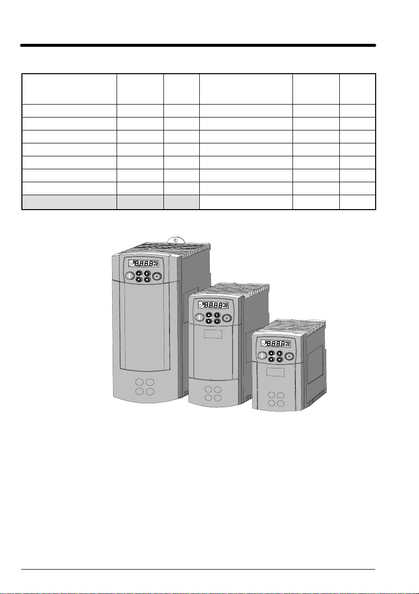
Table 3-1 Watts Loss Ratings
Catalog No.
Output
Current
(A)
Watts
Loss
(W)
Catalog No. Output
Current
(A)
Watts
Loss
ID35D8A1F5–CRH 1.5 26 ID35D4A1F5–CRH 1.5 26
ID35D8A2F2–CRH 2.2 32 ID35D4A02–CRH 2.0 32
ID35D8A03–CRH 3.0 41 ID35D4A2F5–CRH 2.5 40
ID35D8A04–CRH 4.0 52 ID35D4A4F5–CRH 4.5 61
ID35D8A07–CRH 7.0 82 ID35D4A5F5–CRH 5.5 70
ID35D8A10–CRH 10.5 116 ID35D4A09–CRH 9.0 100
ID35D8A16–CRH 16.5 181 ID35D4A12–CRH 12.0 140
ID35D4A16–CRH 16.0 180
Figure 3-1 Inverter Sizes
Size 3
Size 2
Size 1
3–2 Receiving & Installation MN735
Page 14
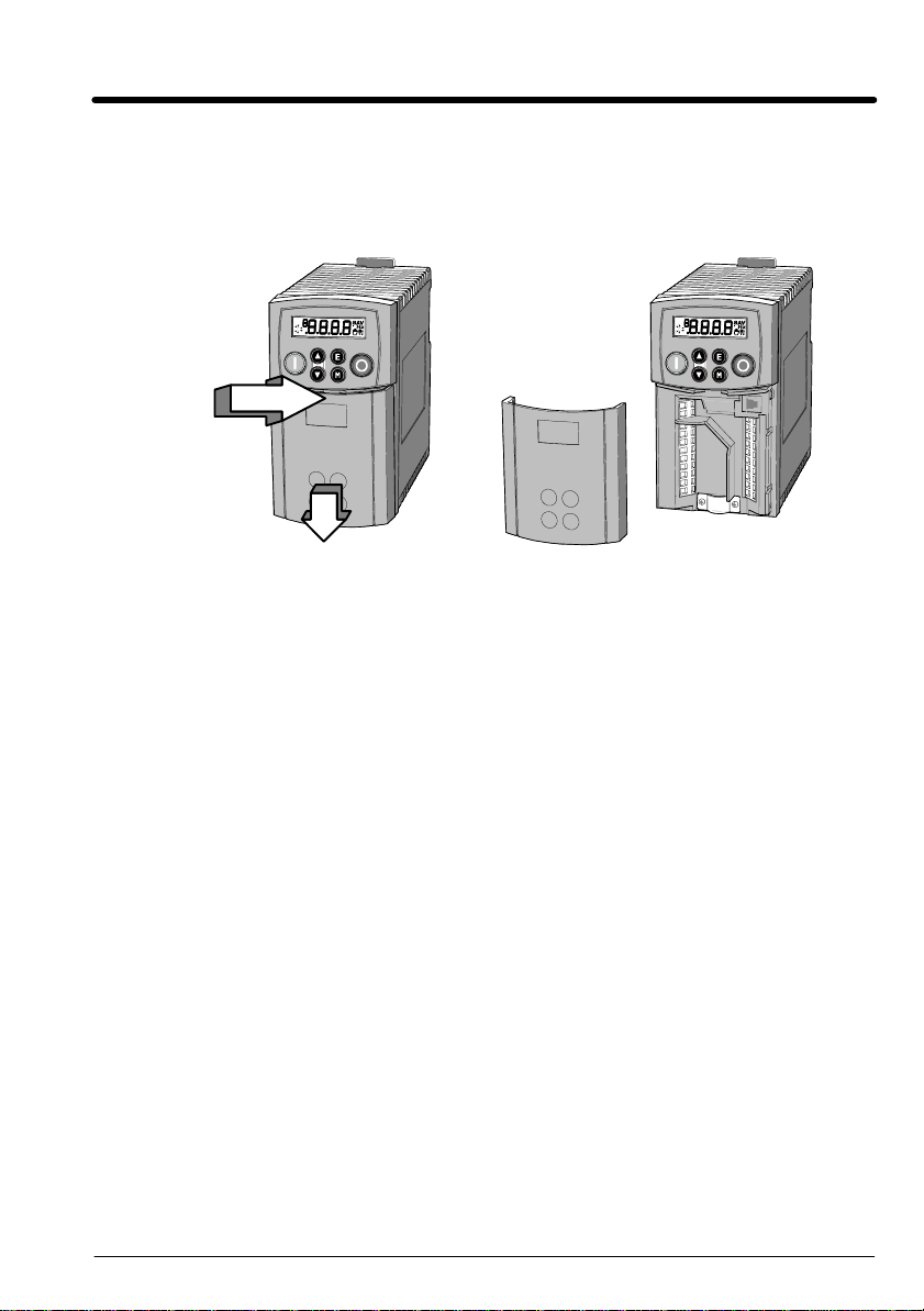
Cover Removal To connect power and signal wires, the cover must be removed. This
1. Press in to
release cover
Power Conditioning
procedure describes how to access all terminal connections inside the
control.
Using your thumbs, press in and slide the cover down as shown in Figure
3-2.
Figure 3-2 Top Cover Removal
2. Slide cover down and remove.
System Grounding Baldor Controls are designed to be powered from standard
three phase power lines that are electrically symmetrical with respect to
ground. System grounding is an important step in the overall installation to
prevent problems.
Ungrounded Distribution System
With an ungrounded power distribution system it is possible to have a
continuous current path to ground through the MOV devices. To avoid
equipment damage, an isolation transformer with a grounded secondary is
recommended. This provides three phase AC power that is symmetrical
with respect to ground.
Input Power Conditioning
Baldor controls are designed for direct connection to standard three phase
lines that are electrically symmetrical with respect to ground. Certain
power line conditions must be avoided. An AC line reactor or an isolation
transformer may be required for some power conditions.
S If the feeder or branch circuit that provides power to the control has
permanently connected power factor correction capacitors, an input
AC line reactor or an isolation transformer must be connected
between the power factor correction capacitors and the control.
S If the feeder or branch circuit that provides power to the control has
power factor correction capacitors that are switched on line and off
line, the capacitors must not be switched while the control is
connected to the AC power line. If the capacitors are switched on line
while the control is still connected to the AC power line, additional
protection is required. TVSS (Transient Voltage Surge Suppressor) of
the proper rating must be installed between the AC line reactor or an
isolation transformer and the AC input to the control.
Receiving & Installation 3–3MN735
Page 15

Line Impedance The Baldor control requires a 1% line impedance minimum . If
the impedance of the incoming power does not meet the requirement for
the control, a 3 phase line reactor can be used to provide the needed
impedance in most cases. Line reactors are optional and are available from
Baldor.
The input impedance of the power lines can be determined as follows:
Measure the line to line voltage at no load and at full rated load.
Use these measured values to calculate impedance as follows:
%Impedance +
(Volts
No Load Speed
(Volts
* Volts
No Load Speed
Full Load Speed
)
)
100
Line Reactors Three phase line reactors are available from Baldor. The line
reactor to order is based on the full load current of the motor (FLA). If
providing your own line reactor, use the following formula to calculate the
minimum inductance required.
0.03)
(V
L +
L* L
Ǹ
(I 3
377)
Where: L Minimum inductance in Henries.
V
L-L
0.03 Desired percentage of input impedance.
Input volts measured line to line.
I Input current rating of control.
377 Constant used with 60Hz power.
Use 314 if input power is 50Hz.
Load Reactors Line reactors may be used at the control output to the motor.
When used this way, they are called Load Reactors. Load reactors serve
several functions that include:
S Protect the control from a short circuit at the motor.
S Limit the rate of rise of motor surge currents.
S Slowing the rate of change of power the control delivers to the motor.
Load reactors should be installed as close to the control as possible.
Selection should be based on the motor nameplate FLA value.
Power Disconnect A power disconnect should be installed between the input
power service and the control for a fail safe method to disconnect power.
The control will remain in a powered-up condition until all input power is
removed from the control and the internal bus voltage is depleted.
Protective Devices Recommended fuse sizes are based on the following:
115% of maximum continuous current for time delay.
150% of maximum continuous current for Fast or Very Fast action.
Note: These general size recommendations do not consider harmonic currents or
ambient temperatures greater than 40°C.
Be sure a suitable input power protection device is installed. Use the
recommended fuses and wire sizes shown in Table 3-2 is based on the use
of copper conductor wire rated at 75 °C. The table is specified for NEMA B
motors.
Reduced Input Voltage Derating All power ratings stated in Section 6 are for
the stated nominal AC input voltages (230 or 460VAC). The power rating of
the control must be reduced when operating at a reduced input voltage.
The amount of reduction is the ratio of the voltage change.
3–4 Receiving & Installation MN735
Page 16
Examples:
A 5hp, 230VAC control operating at 208VAC has a reduced power rating of
4.5hp.
5HP
Likewise, a 3hp, 460VAC control operating at 380VAC has a reduced
power rating of 2.47hp.
3HP
Electrical Installation All interconnection wires between the control, AC power source,
motor, host control and any operator interface stations should be in metal
conduits or shielded cable must be used. Use listed closed loop
connectors that are of appropriate size for wire gauge being used.
Connectors are to be installed using crimp tool specified by the
manufacturer of the connector. Only class 1 wiring should be used.
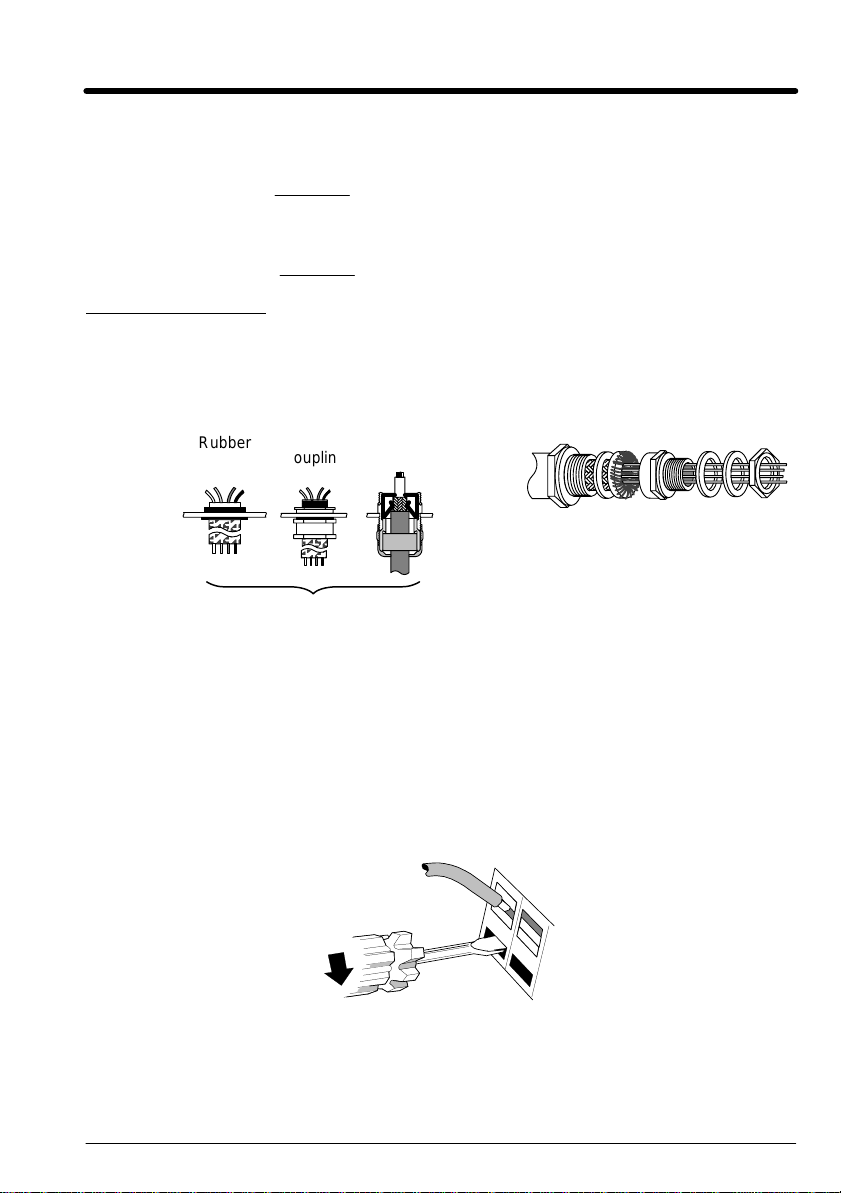
Rubber
Grommet
Holes are required in the enclosure assembly to allow connections to be
made. Use the correct size rubber grommet, conduit coupling or 360
degree coupling.
Clamp Terminals To install a wire into a clamp terminal, first strip wire insulation
to 0.20–0.24 in. (5–6mm). Insert a flat–blade screwdriver, maximum blade
size 0.138 in. (3.5mm) into the adjacent hole. Do not twist or rotate the
screwdriver as this action may damage the terminal. A very slight
downward pressure on the screwdriver should open the terminals and allow
the wire to be inserted. Insert the wire into the clamp opening (Figure 3-4).
Remove the screwdriver. The terminal provides the correct force for a
secure connection.
208VAC
230VAC
380VAC
460VAC
Figure 3-3 Unshielded and Shielded Couplings
Metal
Coupling
+ 4.5hp
+ 2.47hp
360 Degree
Coupling
Figure 3-4 Clamp Terminal
360 Degree Coupling
Receiving & Installation 3–5MN735
Page 17

Table 3-2 Wire Size
Output
Catalog
Number
ID35D8A1F5-CRH 1 1.5 2.3 12 2.5 12 2.5
ID35D8A2F2-CRH 1 2.2 3.3 12 2.5 12 2.5
ID35D8A03-CRH 1 3.0 4.5 12 2.5 12 2.5
ID35D8A04-CRH 1 4.0 6.0 12 2.5 12 2.5
ID35D8A07-CRH 2 7.0 10.5 12 2.5 12 2.5
ID35D2A10-CRH 3 10.5 15.8 10 2.5 10 2.5 12 2.5
ID35D2A16-CRH 3 16.5 24.8 10 2.5 10 2.5 12 2.5
ID35D4A1F5-CRH 2 1.5 2.3 12 2.5 12 2.5 12 2.5
ID35D4A02-CRH 2 2.0 3.0 12 2.5 12 2.5 12 2.5
ID35D4A2F5-CRH 2 2.5 3.8 12 2.5 12 2.5 12 2.5
ID35D4A4F5-CRH 2 4.5 6.8 12 2.5 12 2.5 12 2.5
ID35D4A5F5-CRH 2 5.5 8.3 12 2.5 12 2.5 12 2.5
ID35D4A09-CRH 3 9.0 13.5 10 2.5 10 2.5 12 2.5
ID35D4A12-CRH 3 12.0 18.0 10 2.5 10 2.5 12 2.5
ID35D4A16-CRH 3 16.0 24.0 10 2.5 10 2.5 12 2.5
Size
Current
Cont. Peak
(Amps) (Amps)
L1, L2, L3, N,
GND and Motor
AWG MM2AWG MM2AWG MM
Wire Size
DC+, DBR TH1A, TH1B
Note: All wire sizes based on 75°C copper wire, 40°C ambient temperature, 4-6
conductors per conduit or raceway.
Power Connections The signals are shown in Figure 3-5 and described in
Table 3-3.
1. Remove the cover, shown in Figure 3-2.
2. Loosen the grounded cable clamp, Figure 3-5.
3. Connect the Mains Cable, Motor Cable, Dynamic Brake Cable and
Thermistor Cable wires, if used to their proper clamp terminal, Figure
3-5. Be sure the shields of all shielded cables are in contact with the
grounded cable clamp.
Note: This control must have two separate mains earth grounds connected as
shown in Figures 3-5 and 3-6.
4. Tighten the grounded cable clamp screws to securely hold the cables.
2
3–6 Receiving & Installation MN735
Page 18

Table 3-3 Power Connection Descriptions
idly t
2000Ω
this t
o
Range
above
380/460VAC±10%
with respect to L2, L3.
380/460VAC±10%
with respect to L1, L3.
emperature.
Terminal Description Function
RLY1 Relay Output Normally open, programmable
TH1A Thermistor Connection to motor thermistor It is good practice to protect motors by using
TH1B Thermistor Connection to motor thermistor
Reference
Terminal
L1 Power Input Single and three phase line
L2/NL2Power Input Single phase neutral (or L2 three
contact for a relay output.
Supply protective earth (PE). This terminal must be connected to a protective (earth)
ground for permanent ground.
connection
phase line connection)
230V 1–Phase 460V 3–Phase
Contact closes when the programmed
condition (see Section 4) is true.
No voltage is present on this contact. 6
conditions are available.
thermistors. A typical resistance (up to a
reference temperature of 125_C) is 200Ω,
rising rap
Connect devices in series between TH1A and
TH1B. Jumper TH1A and TH1B if temperature
sensors are not used.
220/240VAC±10%
with respect to L2/N.
220/240VAC±10%
with respect to L1.
L3 Power Input Three phase line connection Not applicable 380/460VAC±10%
DC- No user connection
DC+ Dynamic Brake Connection to external brake
DBR Dynamic Brake Connection to external brake
M1/U
M2/V
M3/W
Power Outputs 3-phase supply connection for
Reference
Terminal
resistor
resistor
motor
Supply protective earth (PE). This terminal must be connected to a protective (earth)
ground for permanent ground.
Not applicable Frame 2 (high volt
Not applicable Frame 2 (high volt
0 to 220/240VAC
0 to 240Hz
with respect to L1, L2.
only) & 3.
See Internal Dynamic
Brake Switch" table
only) & 3.
See Internal Dynamic
Brake Switch" table
0 to 380/460VAC
0 to 240Hz
Receiving & Installation 3–7MN735
Page 19

Size 2 Shown
Figure 3-5 Power and Ground Connections
TH1A and TH1B must
be jumpered if
thermistor is not used
AC Line
Connections
Dynamic Brake
Connections
Motor
Connections
L1, L2, L3, GND
RL1A
RL1B
TH1A
TH1B
L1
L2/N
L3
DC+
DBR
M1/U
M2/V
M3/W
Use 2 Ground
Wires
Motor Cable
Mains Supply
Cable
Use a cable tie
in this area for
control wires.
10
9
8
7
6
5
4
3
2
1
Wire Retainer
(Channel)
Grounded
Cable Clamp
Dynamic Brake Cable
Thermistor Cable
Control Signal Cable
3–8 Receiving & Installation MN735
Page 20

Figure 3-6 Power Connections Continued
10
DIN4/DOUT2
9
8
7
6
5
4
3
2
1
DIN3
DIN2
DIN1
+24V
AOUT1
+10V Ref
AIN2
AIN1
0V
Feedback
Setpoint
See Applications/Modes
10k Speed
Setpoint
Connect 0V to PE (protective earth ground)
for single control installations only. If multiple
controls are used, connect 0V terminals
together and ground to PE at one point only.
Size 1 and 3 Terminal Strips
Size 1
TH1A
TH1B
AC
Line
Motor
L1
L2/N
M1/U
M2/V
M3/W
1φ 230VAC
AC Line
Dynamic
Brake
Motor
Volts or
0–20mA Input
Size 3
TH1A
TH1B
L1
L2
L3
DC+
DBR
DC–
M1/U
M2/V
M3/W
Thermistor Connections (connections are shown in Figure 3-5).
This input is provided for over–temperature detection for motors that have
an internal thermistor. There is no polarity to the thermistor connections.
This provides “Basic” insulation only to the SELV control circuits and
assumes the motor has “Basic” insulation to the windings/mains circuits.
The thermistor type supported is PTC ‘Type A’ as defined in IEC 34–11 Part
2. The resistance thresholds are:
Rising temperature trip resistance: 1650 to 4000 ohms
Falling temperature trip reset resistance 750 to 1650 ohms
If the motor does not have an internal thermistor, you should disable the
thermistor trip function by:
Receiving & Installation 3–9MN735
3φ 460VAC
Page 21

1. Connecting a jumper wire between the thermistor terminals TH1A and
U
Volt-f
0-250VAC/24VDC
TH1B. or
2. Set the parameter Invert Thermistor Input
TRIPS MENU
to 1.
Signal Connections Wire sizes between 12AWG and 28AWG (2.5mm2 to
0.08mm
2
) can be used.
1. With the cover removed, connect the analog and digital inputs and
outputs as shown in Figure 3-5.
The signals are described in Table 3-4.
2. Install the front cover.
Table 3-4 Analog/Digital Signal Descriptions
Terminal
(SELV)
RL1A
RL1B
10 DIN4/
9 DIN3 Digital Input 3. 0-24V source
8 DIN2 Digital Input 2. 0-24V source
7 DIN1 Digital Input 1. 0-24V source
6 +24V 24V ć 24V supply for digital I/O 50mA max
5 AOUT1 Analog Output ć 10mA maximum 0-10V
4 10VREF 10V reference (10mA maximum loading) 10V
3 AIN2 Analog Input 2 0-10V, 4-20mA
2 AIN1 Analog Input 1 - Setpoint. If unused, connect to 0VDC. 0-10V
1 0V 0V - Reference for Analog/Digital I/O
Signal Name Description Range
ser Relay
DOUT2
ree contact - 4A maximum, non-inductive
Configurable I/O, Digital Input 4 or Digital Output 2. 0-24V source
For single control installations, connect pin 1 (0V) to
PE.
For multiple control installations, connect the 0V
terminals of each control together. Then connect only
one control to PE.
open collector
open collector
open collector
open collector
0V
3–10 Receiving & Installation MN735
Page 22

External Brake Resistor
Connect the dynamic brake resistor between terminals DC+ and DBR as
shown in Figure 3-5 and 3-6.
User Relay A customer provided, external DC or AC power supply must be used
if relay output is to be used.
Note: Contact is rated to 250V @ 4A
Volts
Load
Customer Provided Load
resistive (non–inductive).
Contact is open
when power is on
and no faults are
present.
Control
RL1A
RL1B
Applications/Modes There are 6 operating modes. Each mode configures the
terminal strip wiring for a specific application. The following diagrams
document the terminal strip wiring for each (Application 0 to Application 5).
Note: Parameter values are not changed by loading a new Application.
How to Load an Application
In the
The Applications are stored in this menu.
Use the
Press the
menu, go to and press the key.
keys to select the appropriate Application by number.
key to load the Application.
Receiving & Installation 3–11MN735
Page 23

1 – Keypad Mode
In Keypad mode, the control is operated by the keypad and opto isolated
inputs and the analog command inputs are ignored. The analog output
remain active.
Figure 3-7 Keypad Connection Diagram
Speed Output
Pot Reference
Analog Input 2
Analog Input 1
Analog GND
+24VDC
10
9
8
7
6
5
4
3
2
1
Fault
1 Analog GND. Reference for analog inputs.
2 Not used.
3 Not used.
4 +10VDC reference voltage for potentiometer.
5 Analog output that represents the commanded speed output.
6 +24VDC for Optical Inputs power.
7 Not used.
8 Not used.
9 Not used.
10 Not used.
RLY1Digital output that represents the fault status.
RLY1A
RLY1B
3–12 Receiving & Installation MN735
Page 24

2 – Standard Run 3 Wire Mode
In Standard Run mode, the control is operated by the opto isolated inputs
and the analog command input. The opto inputs can be switches as shown
in Figure 3-8 or logic signals from another device.
Figure 3-8 Standard Run Connection Diagram
Analog IN
Select
Open
Closed
Analog Input 1 = 0–10VDC Setpoint
Analog Input 2 = 4–20mA Setpoint
Command
Analog Input 1
Analog Input 2
10K Pot or
0-10VDC
Analog IN SEL
Stop
Run REV
Run FWD
+24VDC
Speed Output
Pot Reference
Analog Input 2
Analog Input 1
Analog GND
10
9
8
7
6
5
4
3
2
1
Fault
1 Analog GND. Reference for analog inputs.
2 Setpoint 0–10VDC. Single ended analog voltage input, referenced to 1.
3 Setpoint 4–20mA. Single ended analog current input, referenced to 1.
4 +10VDC reference voltage for potentiometer.
5 Analog output that represents the commanded speed output.
6 +24VDC for Optical Inputs power.
7 Momentary CLOSED starts motor operation in the Forward direction.
8 Momentary CLOSED starts motor operation in the Reverse direction.
9 Momentary OPEN motor decels to stop.
10 Analog IN Select. OPEN selects Analog Input 1 (2).
CLOSED selects Analog Input 2 (3).
RLY1Digital output that represents the fault status.
RLY1A
RLY1B
Receiving & Installation 3–13MN735
Page 25

3 – 3 Speed 2 Wire Mode
In 3 speed 2 wire mode, the control is operated by the opto isolated inputs
and the analog command input. The opto inputs can be switches as shown
in Figure 3-9 or logic signals from another device.
Figure 3-9 3 Speed Connection Diagram
Speed Select
1 2 Command
Open
Open
Closed
Closed
Open
Closed
Open
Closed
Analog Input 1 & 2 (Add)
Preset Speed 1
Preset Speed 2
Preset Speed 3
Speed Select 2
Speed Select 1
Speed Output
Related Parameters
p302 Preset Speed 1
p303 Preset Speed 2
p304 Preset Speed 3
10K Pot or
Pot Reference
Analog Input 2
Analog Input 1
0-10VDC
Analog Input 1 = 0–10VDC Setpoint
Analog Input 2 = 4–20mA Setpoint
Fault
1 Analog GND. Reference for analog inputs.
2 Setpoint 0–10VDC. Single ended analog voltage input, referenced to 1.
3 Setpoint 4–20mA. Single ended analog current input, referenced to 1.
4 +10VDC reference voltage for potentiometer.
5 Analog output that represents the commanded speed output.
6 +24VDC for Optical Inputs power.
7 CLOSED starts motor operation in the Forward direction.
8 CLOSED starts motor operation in the Reverse direction.
9 Speed Select input 1. Inputs 9 & 10 select preset speeds 1 to 3.
10 Speed Select input 2. Inputs 9 & 10 select preset speeds 1 to 3.
RLY1Digital output that represents the fault status.
Run REV
Run FWD
+24VDC
Analog GND
10
9
8
7
6
5
4
3
2
1
RLY1A
RLY1B
3–14 Receiving & Installation MN735
Page 26

4 – EPOT 3 Wire Mode (Electronic Potentiometer)
In EPOT 3 wire mode, the control is operated by the opto isolated inputs
and the analog command input. The opto inputs can be switches as shown
in Figure 3-10 or logic signals from another device.
Figure 3-10 EPOT Connection Diagram
Note:
Speed Command = Analog1 + Analog2 + EPOT
Analog Input 1 = 0–10VDC Setpoint
Analog Input 2 = 4–20mA Setpoint
10K Pot or
0-10VDC
Decrease
Increase
Stop
Run FWD
+24VDC
Speed Output
Pot Reference
Analog Input 2
Analog Input 1
Analog GND
10
9
8
7
6
5
4
3
2
1
Fault
1 Analog GND. Reference for analog inputs.
2 Setpoint 0–10VDC. Single ended analog voltage input, referenced to 1.
3 Setpoint 4–20mA. Single ended analog current input, referenced to 1.
4 +10VDC reference voltage for potentiometer.
5 Analog output that represents the commanded speed output.
6 +24VDC for Optical Inputs power.
7 Momentary CLOSED starts motor operation in the Forward direction.
8 Momentary OPEN motor decels to stop.
9 Momentary CLOSED increases motor speed while contact is closed.
10 Momentary CLOSED decreases motor speed while contact is closed.
RLY1Digital output that represents the fault status.
RLY1A
RLY1B
Receiving & Installation 3–15MN735
Page 27

5 – EPOT 2 Wire Mode (Electronic Potentiometer)
In EPOT 2 wire mode, the control is operated by the opto isolated inputs
and the analog command input. The opto inputs can be switches as shown
in Figure 3-11 or logic signals from another device.
Figure 3-11 EPOT Connection Diagram
Note:
Speed Command = Analog1 + Analog2 + EPOT
Analog Input 1 = 0–10VDC Setpoint
Analog Input 2 = 4–20mA Setpoint
10K Pot or
0-10VDC
Decrease
Increase
Run REV
Run FWD
+24VDC
Speed Output
Pot Reference
Analog Input 2
Analog Input 1
Analog GND
10
9
8
7
6
5
4
3
2
1
Fault
1 Analog GND. Reference for analog inputs.
2 Setpoint 0–10VDC. Single ended analog voltage input, referenced to 1.
3 Setpoint 4–20mA. Single ended analog current input, referenced to 1.
4 +10VDC reference voltage for potentiometer.
5 Analog output that represents the commanded speed output.
6 +24VDC for Optical Inputs power.
7 CLOSED starts motor operation in the Forward direction.
8 CLOSED starts motor operation in the Reverse direction.
9 Momentary CLOSED increases motor speed while contact is closed.
10 Momentary CLOSED decreases motor speed while contact is closed.
RLY1Digital output that represents the fault status.
RLY1A
RLY1B
3–16 Receiving & Installation MN735
Page 28

6 – PID 2 Wire Mode
In PID 2 wire mode, the control is operated by the opto isolated inputs and
the analog command input. The opto inputs can be switches as shown in
Figure 3-12 or logic signals from another device.
Figure 3-12 PID Connection Diagram
Process
Enable
Open
Closed
Analog Input 1 = 0–10VDC Setpoint
Analog Input 2 = 4–20mA Feedback
Command
Analog Input 1 (Speed Ref)
PID
Process Enable
Speed Output
Pot Reference
Analog Input 2
Related Parameters
p8 Jog Speed
Jog Accel
Jog Decel
10K Pot or
0-10VDC
Analog Input 1
Analog GND
Fault
1 Analog GND. Reference for analog inputs.
2 PID Setpoint 0–10VDC. Single ended analog voltage input, referenced to 1.
3 PID Feedback 4–20mA. Single ended analog current input, referenced to 1.
4 +10VDC reference voltage for potentiometer.
5 Analog output that represents the commanded speed output.
6 +24VDC for Optical Inputs power.
7 Momentary CLOSED starts motor operation in the Forward direction. In Jog mode
(10 Closed), jogs motor in forward direction as long as switch is closed.
8 Momentary CLOSED starts motor operation in the Reverse direction. In Jog mode
(10 Closed), jogs motor in reverse direction as long as switch is closed.
9 CLOSED enables process mode. OPEN selects Analog Input 1 setpoint.
10 CLOSED places control in Jog mode. Forward and Reverse run are used to Jog the motor at
Jog speed.
RLY1Digital output that represents the fault status.
Jog
Run REV
Run FWD
+24VDC
10
9
8
7
6
5
4
3
2
1
RLY1A
RLY1B
Receiving & Installation 3–17MN735
Page 29

3–18 Receiving & Installation MN735
Page 30

Section 4
Start–Up and Operation
Keypad Description
Figure 4-1 Keypad Description
Display
Local
Run
Programming Keys
Key Operation Description
Escape Navigation – Displays the previous level’s menu
Menu Navigation – Displays the next menu level, or the first parameter
Increment Navigation – Move upwards through the menu system
Decrement Navigation – Move down through the menu system
Run Local Mode – Run the drive
Stop Local Mode – Stops the drive. Trip Reset in all modes
Parameter – Returns to the parameter list
Trip Acknowledge – Acknowledges displayed Trip or Error
message
of the current Menu
Parameter – Moves cursor to the left when the parameter is
adjustable
Parameter – Increase value of the displayed parameter
Local Mode – Increase value of the local setpoint
Parameter – Decrease value of the displayed parameter
Local Mode – Decrease value of the local setpoint
Navigation – Press and hold to toggle between Local and
Remote Control modes (refer to Special Menu Features)
Local
Stop
The keypad provides local control and monitoring of the Inverter. Remove
it by simply pulling it from the drive. To install it, push it back into place.
Start–Up and Operation 4–1MN735
Page 31

Display
when in the Parameter menu
when in the Setup menu
when displaying an Alarm code
a negative parameter value
Displays the units for the value:
S for time in seconds, A for current in Amps
V for voltage in Volts, % for percentage
Hz for frequency in Hertz
Represents a rotating motor shaft:
CW = forward rotation
CCW = reverse rotation.
Parameter numbers or values, trip information,
error codes etc. See Drive Status Indications.
Local mode.
(Remote mode when
hand is not visible.
Drive Status Indications (shown on keypad)
Display Status Indication and Meaning Possible Cause
READY/HEALTHY No alarms present.
Remote mode selected
PASSWORD Current password must
be entered before this parameter may
be altered.
LOCAL Local mode selected Added or removed from the display
Enter password to change the parameter.
(See password protection).
letter–by–letter to indicate entering or
leaving Local mode
Diagnostics Menu
Display Name Description
FREQUENCY The current output frequency in Hertz
SPEED SPT The set point as a percentage of MAX SPEED
DC LINK VOLTS VAC √2 = dc link Volts
Not Used
MTR CURRENT The current load value in Amps
4–2 Start–Up and Operation MN735
Page 32

Menu System There are three menu levels as shown in this diagram:
Menu Level 1 Menu Level 2 Parameter Level
Parameter Menu
Remote
Operation
Hold for
2 sec
Local Setpoint
SETUP MENU
Hold for
1 sec
Diagnostic Menu
Menu Level 3
Inputs Menu
Outputs Menu
Trips Menu
Miscellaneous Setup Menu
Start–Up and Operation 4–3MN735
Page 33

Power Up On initial power–up, the drive is in Local control mode and the keypad will
display the Local Setpoint.
.
All parameters are at factory settings. Any changes to these conditions are
automatically saved. The drive will initialize on subsequent power–ups with
the previously saved settings and control mode.
How to Change a Parameter Value
You can change the values of parameters stored in the and
menus. Refer to “Parameter Definitions” for further information.
• View the parameter to be edited and press
to display the
parameter’s value.
• Select the digit to be changed (pressing the
key moves the
cursor from right to left).
• Use the
keys to adjust the value. Hold the key momentarily
to adjust the value marginally, or hold the key to make rapid changes;
the rate of change varies with the time held.
• Press
to return to the parameter display. The new value is
stored.
Special Menu Features
Reset to Factory Settings (2 button Reset)
Turn power on while pressing the Y
and B keys. This loads or restores
the factory settings and application 1.
Select Local or Remote
Remote Control Mode: Allows control using digital and analog inputs and
outputs. Local control keys are inactive when Remote control mode is
selected. In remote mode, the control uses a remote setpoint (analog
Input 1).
Local Control Mode: Provides local control and monitoring of the drive
using the keypad. In local mode, the control uses the local setpoint
parameter (value is adjusted using the keypad).
Note: You can only change between Local and Remote control when the Inverter
is “stopped”, and either
or the Local Setpoint is displayed.
Remote to Local
Note: For safety reasons, the control will not return to Remote mode if this will
cause the drive to start. Verify that the RUN and JOG inputs are low.
HOLD
Then press
4–4 Start–Up and Operation MN735
Page 34

Hold this key down until
the display shows
REMOTE
Hold this key down until
the display spells
LOCAL
Password Protection
When activated, the password prevents unauthorized parameter
modification by making all parameters “read–only”. Password protection is
set–up using the
Steps ACTIVATE TEMPORARY DE-ACTIVATION REMOVE PASSWORD
Actions Display Actions Display Actions Display
1 Try to edit any
2
3 Original
4 A drive will power-up with the last
Default = 0000, de-activated
Any other value is a password
parameter.
parameter with
password activated
parameter
displayed,
password
de-activated
password status. Temporary
de-activation is lost on
power-down.
Quick Application Selection
Press and hold theStop key.
Power up the control.
Continue to hold the key for at least 1 second.
You can navigate immediately to the APPLICATION
parameter,
P
1, from this power–up condition.
Then, press the
Use the
keys to select the appropriate Application by number.
Press the
key to display the current Application.
key to load the Application.
Start–Up and Operation 4–5MN735
Page 35

Parameter Definitions You can program the Inverter for specific applications. The
Inverter is supplied with pre–programmed applications that can be used as
starting points for application–specific programming. Programming is simply
selecting an application, changing some of the parameter values and finally
saving the changes. Each application configures the terminal wiring for a
differently. The Inverter retains the new settings during power–down. The
next time the inverter is powered up, the new settings will be used.
Note: Motor parameters are not changed when a new application is loaded.
Table 4-1 Parameter Definitions
Display
Parameter Description Range Factory
Setting
APPLICATION Selects the applicaton to be used
MAX SPEED The frequency at which the control will run
MIN SPEED The minimum frequency at which the control will
ACCEL TIME The time taken for the control output frequency
DECEL TIME The time taken for the control output frequency
MOTOR
CURRENT
BASE
FREQUENCY
JOG
SETPOINT
RUN STOP
MODE
V/F SHAPE
Application 1: Keypad mode
Application 2: Standard Run 3-Wire
Application 3: 3 Speed 2-Wire
Application 4: EPOT 3-Wire
Application 5: EPOT 2-Wire
Application 6: PID 2-Wire
when maximum setpoint is applied
run.
to ramp up from zero to MAX SPEED
to ramp down from MAX SPEED to zero
This parameter contains the motor nameplate
full-load line current
The output frequency at which maximum
voltage is reached. The default is Product Code
dependent.
Speed the control will run at if the Jog input is
high
RAMP : The motor speed is reduced to zero at
a rate set by DECEL TIME (
pulse is applied at end of ramp
COAST : The motor is allowed to freewheel to a
standstill
INJECTION : On a stop command, the motor
volts are rapidly reduced at constant frequency
to deflux the motor. A low frequency braking
current is then applied until the motor speed is
almost zero. This is followed by a timed DC
pulse to hold the motor shaft.
OUTPUT VOLTS
00%
LINEAR
f
= BASE FREQUENCY
B
P
5). A 2 second
QUADRATIC LAW
f
B
CONSTANT
POWER RANGE
FREQUENCY
0= Application 0
1= Application 1
2= Application 2
3= Application 3
4= Application 4
5= Application 5
6= Application 6
1
7.5 to 240.0Hz 60.0Hz
-100.0 to 100.0% 0.0%
0.0 to 3000.0s 5.0s
0.0 to 3000.0s 5.0s
Product
code
dependent
Product
code
dependent
25.0 to 240.0Hz 60.0Hz
-100.0 to 100.0% 12.0%
0=RAMP
1=COAST
2=INJECTION
0=LINEAR
1=FAN
0
0
4–6 Start–Up and Operation MN735
Page 36

Table 4-1 Parameter Definitions Continued
Display Parameter Description Range Factory
Setting
NORMAL
DUTY
FIXED BOOST
PASSWORD A password may be set to prohibit
Parameters P301 to P308 are visible in the PAR menu when Application 3 is selected in parameter P1
PRESET 0 Preset 0 is normally connected to Setpoint. -100.00 to 100.00% -
PRESET 1 A user-adjustable speed preset -100.00 to 100.00% 20.00%
PRESET 2 A user-adjustable speed preset -100.00 to 100.00% 50.00%
PRESET 3 A user-adjustable speed preset -100.00 to 100.00% 100.00%
PRESET 4 A user-adjustable speed preset -100.00 to 100.00% -10.00%
PRESET 5 A user-adjustable speed preset -100.00 to 100.00% -20.00%
PRESET 6 A user-adjustable speed preset -100.00 to 100.00% -50.00%
PRESET 7 A user-adjustable speed preset -100.00 to 100.00% -100.00%
Parameters P401 to P404 are visible in the PAR menu when Application 4 is selected in parameter P1
R/L RAMP
TIME
R/L MAX
VALUE
R/L MIN VALUE The minimum value for the ramp output -100.0 to 100.0% 0.0%
R/L RESET
VALUE
HEAVY DUTY: the current limit is set to 150%
motor current, inverse time delay is set to 30s
NORMAL DUTY: the current limit is set to
110% motor current, inverse time delay is set
to 10s
P
When
11 is changed from FAN to LINEAR,
P
12 is set to 0 (Heavy Duty)
P
When
11 is changed from LINEAR to FAN,
P
12 is set to 1 (Normal Duty)
P
12 can be changed independently
OUTPUT VOLTS
100%
INCREASED
TORQUE
FLUXING
25%
0%
f
B
= BASE FREQUENCY
unauthorised adjustment of parameters. When
P
99 is set to non-zero you will be required to
match this value before parameters can be
adjusted
The time taken to ramp the Raise/Lower output
from 0.00% to 100.00% of its value
NORMAL FLUXING
INCREASING
BOOST
CONSTANT
POWER RANGE
f
B
FREQUENCY
0=False
1=True
0
0.00 to 25.00% 5.00%
0000 ć FFFF 0000
0.0 to 600.0s 10.0s
The maximum value for the ramp output -100.0 to 100.0% 100.0%
The value the output is set to when Reset is
TRUE, when DIN4 (terminal 10) is 24V in
Application 4
-100.00 to 100.00% 0.00%
Start–Up and Operation 4–7MN735
Page 37

Table 4-1 Parameter Definitions Continued
Display Parameter Description Range Factory
Setting
Parameters P501 and P502 are visible in the PAR menu when Application 5 is selected in parameter P1
PI P GAIN The PID P"roportional gain 0.00 to 100.00 1.00
PI I GAIN The PID I"ntegral gain 0.00 to 100.00 0.00
PID D GAIN ~
PID D FILTER
TC ~
PID FEEDBACK
GAIN ~
PID LIMIT ~
PID SCALING~An overall scale factor which is applied after the
PID ERROR~Error=(Setpoint-Feedback) x (Feedback Gain) x.xx % x.xx %
PID OUTPUT~The output of the PID function block x.xx % x.xx %
DIN 1 INVERT True =Inverts the input signal. 0= False
DIN 2 INVERT True =Inverts the input signal. 0= False
DIN 3 INVERT True =Inverts the input signal. 0= False
DIN 4 INVERT True =Inverts the input signal. 0= False
AIN 1 SCALE
The PID D"erivative gain 0.00 to 100.00 0.00
A first order lag filter to help attenuate high
frequency noise on the derivative term. This
parameter determines the filter time constant.
A multiplier applied to the PID feedback signal -10.00 to 10.00 1.00
Determines the maximum positive and negative
excursion (Limit) of the PID output
PID positive and negative limit clamps
SET::IN Menu
TYPE
SCALE
OFFSET
0.05 to 10.00s 0.05s
0.00 to 300.00% 0.00
-3.0000 to 3.0000 0.00
1= True
1= True
1= True
1= True
-150.0 to 150.0% 100.0%
0
0
0
0
UNPROCESSED
INPUT
0 to 100% of selected TYPE
AIN 1 OFFSET -100.0 to 100.0% 0.00%
AIN 1 TYPE 0= 0-10V
AIN 2 SCALE
AIN 2 OFFSET -100.0 to 100.0% 0.0%
AIN 2 TYPE 0= 0-10V
4–8 Start–Up and Operation MN735
TYPE
UNPROCESSED
INPUT
0 to 100% of selected TYPE
X
SCALE
X
OFFSET
+
+
VALUE
1= 0-5V
-150.0 to 150.0% 100.0%
VALUE
1= 0-5V
2= 0-20mA
3= 4-20mA
0
3
Page 38

Table 4-1 Parameter Definitions Continued
Display Parameter Description Range Factory
Setting
SET::IN Menu Continued
DIN 1 VALUE~The input signal after inversion (if any). 0= False
DIN 2 VALUE~The input signal after inversion (if any). 0= False
DIN 3 VALUE~The input signal after inversion (if any). 0= False
DIN 4 VALUE~The input signal after inversion (if any). 0= False
1= True
1= True
1= True
1= True
AIN 1 VALUE~The analog input signal with scaling and offset. x.x% x.x%
AIN 2 VALUE~The analog input signal with scaling and offset. x.x% x.x%
SET::OUT Menu
AOUT 1
SOURCE
AOUT 1 SCALE
ANALOG OUTPUT
0 NONE
1 DEMAND %
2 CURRENT %
3 PI ERROR %
4 RAISE/LOWER
OUTPUT%
SCALE
OFFSET
Scale
Offset
Absolute
ABS
0= NONE
1= DEMAND
2= CURRENT
3= PI ERROR
0–10V
4= RAISE/LOWER
OUTPUT
-300.0 to 300.0 100.0%
0
0
0
0
1
AOUT 1
OFFSET
AOUT 1
ABSOLUTE
AOUT 1 VALUE
~
DOUT 2
SOURCE
DOUT 2
INVERT
DOUT 2
VALUE ~
RELAY
SOURCE
Value
X
DIN4 / DOUT2
0 NONE
1 HEALTH
2 TRIPPED
3 RUNNING
4 AT ZERO
5 AT SPEED
6 AT LOAD
+
Invert
Output
X
(OUTPUT) As SIP01. Set to 0 for applications
1 & 5.
The output signal that represents the OP21
choice.
RELAY
0 NONE
1 HEALTH
2 TRIPPED
3 RUNNING
4 AT ZERO
5 AT SPEED
6 AT LOAD
Invert
Output
Output
-300.0 to 300.0% 0.00%
0= False
1= True
-300.0 to 300.0% 0.0%
0= NONE (DIN4)
1= HEALTH
2= TRIPPED
3= RUNNING
4= AT ZERO
5= AT SPEED
6= AT LOAD
As SIP01 0
0= False
1= True
0= NONE
1= HEALTH
2= TRIPPED
3= RUNNING
4= AT ZERO
5= AT SPEED
6= AT LOAD
Start–Up and Operation 4–9MN735
0
0
0
2
Page 39

Table 4-1 Parameter Definitions Continued
Display Parameter Description Range Factory
Setting
RELAY INVERT True =Inverts the input signal. 0= False
RELAY VALUE~The output signal that represents the OP31
choice.
1= True
0= False
1= True
SET::TRIP Menu
DISABLE LOOP Disables LOST I LOOP trip (4-20mA) 0= Trip Enabled
AIN2
OVERLOAD
DISABLE
STALL
DISABLE
MOTOR
OVERTEMP
Disables the overload trip (Terminal 3) 0= Trip Enabled
Disables STALL trip 0= Trip Enabled
Disables the motor thermistor trip 0= Trip Enabled
1= Trip Disabled
1= Trip Disabled
1= Trip Disabled
1= Trip Disabled
SET::SETP Menu
Inverse Time Disables the inverse time trip 0= Trip Enabled
Display
(Keypad)
Disables the display (keypad) trip 0= Trip Enabled
1= Trip Disabled
1= Trip Disabled
Jog Accel Time As P4, for Jog 0.0 to 3000.0s 1.0
Jog Decel Time As P5, for Jog 0.0 to 3000.0s 1.0
Ramp Type Selects the ramp type 0=LINEAR
S Ramp Jerk Rate of change of acceleration of the curve in
S Ramp
Continuous
Skip
Frequency 1
Skip Frequency
Band 1
Skip
Frequency 2
Skip Frequency
Band 2
Auto Restart
Attempts
Auto Restart
Delay
Auto Restart
Triggers
units per second
When True and the S Ramp is selected, forces
a smooth transition if the speed setpoint is
changed when ramping. The curve is controlled
by the S Ramp Jerk parameter.
When False, there is an immediate transition
from the old curve to the new curve
The center frequency of skip band 1 in Hz 0.0 to 240.0 Hz 0.0
The width of skip band 1 in Hz 0.0 to 60.0 Hz 0.0
The center frequency of skip band 2 in Hz 0.0 to 240.0 Hz 0.0
The width of skip band 2 in Hz 0.0 to 60.0 Hz 0.0
Determines the number of restarts that will be
permitted before requiring an external fault
reset
The delay between restart attempts for a trip
included in Auto Restart Triggers and Auto
Restart Triggers+. The delay is measured from
all error conditions clearing
Allows Auto Restart to be enabled for a
selection of trip conditions. Refer to Section 5
3
1=S
0.01 to 100.00s
0=FALSE
1=TRUE
0 to 10 0
0.0 to 600.0 s 10.0s
0x0000 to 0xFFFF 0x0000
0
0
1
0
0
0
1
0
0
3
10.00s
1
3
4–10 Start–Up and Operation MN735
Page 40

Table 4-1 Parameter Definitions Continued
Display Parameter Description Range Factory
Setting
Auto Restart
Triggers+
Local MIN
Speed ~
Enabled Keys
~
Application Lock~True prevents editing of parameter P1. 0=FALSE
Detailed Menus True allows Full menu display.
Allows Auto Restart to be enabled for a
selection of trip conditions. Refer to Section 5
The magnitude of the minimum setpoint that will 0.0 to 100.0 % 0.0%
False hides parameters indicated with ~
0x0000 to 0xFFFF 0x0000
0
1=TRUE
0=FALSE
1=TRUE
0
0
Start–Up and Operation 4–11MN735
Page 41

PI Terms PI is used to control the response of any closed loop system. It is
used specifically in system applications involving the control of drives to
provide zero steady state error between Setpoint and Feedback, together
with good transient performance.
P
Proportional Gain (
501)
This is used to adjust the basic response of the closed loop control system.
The PI error is multiplied by the Proportional Gain to produce an output.
Integral (
P
502)
The Integral term is used to reduce steady state error between the setpoint
and feedback values of the PI. If the integral is set to zero, then there will
always be a steady state error.
P Gain
Error
Setpoint
(AIN1)
Feedback
(AIN2)
+
–
I Gain dt
+
+
Output
S Functions as P, PI controller
S Single symmetric limit on output
A Method for Setting–up the PI Gains
Underdamped (oscillatory)
Critically Damped
OUTPUT
SETPOINT
4–12 Start–Up and Operation MN735
Overdamped
Page 42

The gains should be set–up so that a critically damped response is
achieved for a step change in setpoint. An underdamped or oscillatory
system can be thought of as having too much gain, and an overdamped
system has too little.
To set up the P gain, set the I gain to zero. Apply a step change in setpoint
that is typical for the System, and observe the response. Increase the gain
and repeat the test until the system becomes oscillatory. At this point,
reduce the P gain until the oscillations disappear. This is the maximum
value of P gain achievable.
If a steady state error is present, i.e. the feedback never reaches the
setpoint value, the I gain needs to be increased. As before, increase the I
gain and apply the step change. Monitor the output. If the output becomes
oscillatory, reduce the P gain slightly. This should reduce the steady state
error. Increasing the I gain further may reduce the time to achieve zero
steady state error.
These values of P and I can now be adjusted to provide the exact response
required for this step change.
Product Related Parameter Values
Frequency Dependent Parameters
50Hz default 60Hz default
MAX SPEED 50 60
BASE FREQUENCY 50 60
Power Dependent Parameters
Inverter Size Factory
MOTOR
CURRENT
Size 1 : 0.25kw 230V
Size 1 : 0.37kw 230V
Size 1 : 0.55kw 230V
Size 1 : 0.75kw 230V
Size 2 : 1.1kw 230V
Size 2 : 1.5kw 230V
Size 2 : 1.5kw 460V
Size 2 : 2.0kw 460V
Size 2 : 2.5kw 460V
Size 2 : 3.5kw 460V
Size 2 : 4.5kw 460V
Size 2 : 5.5kw 460V
Size 3 : 6.8kw 460V
Size 3 : 9.0kw 460V
Size 3 : 12.0kw 460V
Size 3 : 16.0kw 460V
Setting
1.5A
2.2A
3.0A
4.0A
5.5A
7.0A
1.5A
2.0A
2.5A
3.5A
4.5A
5.5A
6.8A
9.0A
12.0A
16.0A
Start–Up and Operation 4–13MN735
Page 43

Routine Maintenance
Periodically inspect the Inverter for build–up of dust or obstructions that
may affect cooling. Remove any build–up using dry air .
Saving Your Application Data
In the event of a repair, application data will be saved whenever possible.
However, you should record your application settings before returning the
unit. You should actually record the settings after programming. When a
failure occurs, you may not be able to access the parameter values.
Contact Baldor to arrange for the repair.
Disposal This product contains materials which are consignable waste under the
Special Waste Regulations 1996 which complies with the EC Hazardous
Waste Directive – Directive 91/689/EEC. We recommend you dispose of
the appropriate materials in accordance with the valid environmental control
laws. The following table shows which materials can be recycled and which
have to be disposed of in a special way.
Material
Recycle Disposal
metal yes no
plastic materials yes no
printed circuit board no yes
The printed circuit board should be disposed of in one of two ways:
1. High temperature incineration (minimum temperature 1200_C) by an
incinerator authorized under parts A or B of the Environmental
Protection Act.
2. Disposal in an engineered land fill site that is licensed to take
aluminium electrolytic capacitors. Do not dispose of in a land fill site
set aside for domestic waste.
Packaging
During transport our products are protected by suitable packaging. This is
entirely environmentally compatible and should be taken for central
disposal as secondary raw material.
4–14 Start–Up and Operation MN735
Page 44

Section 5
Troubleshooting
Trips The trip display message is briefly displayed repeatedly (flashing) on the
screen to warn of an imminent trip. Some trip conditions need time to take
effect. The warning can allow you time to resolve the situation. The
message will clear when you use the keypad, but after a short time will
reappear until the problem is resolved, or the drive trips.
When a trip occurs, the control’s power stage is immediately disabled
causing the motor and load to coast to a stop. The trip is latched until action
is taken to reset it. This ensures that trips due to transient conditions are
captured and the Inverter is disabled, even when the original cause of the
trip is no longer present. At this time, the activated alarm is displayed on
the keypad display.
Reset a Trip
All trips must be reset before the Inverter can be re–enabled. A trip can
only be reset once the trip condition is no longer active, i.e. a trip due to a
heatsink over–temperature will not reset until the temperature is below the
trip level. You can reset the trip as follows:
1. Press the
(STOP) key to reset the trip and clear the alarm from
the display.
2. Remove and then re–apply the RUN command and the drive will run
normally.
Success is indicated by either
Display Trip Message and Meaning Possible Reason for Trip
DC LINK HIGH
The Inverter internal dc link
voltage is too high
DC LINK LOW DC LINK low trip. Supply is too low/power down
or the Local Setpoint being displayed.
The supply voltage is too high
Trying to decelerate a large inertia load too
quickly; DECEL TIME time too short
The brake resistor is open circuit (400V unit
only)
OVERCURRENT
The motor current being drawn
from the Inverter is too high
HEATSINK
OVERTEMPERATURE
Drive heatsink temperature >
100ºC
Trying to accelerate a large inertia load too
quickly; ACCEL TIME time too short
Trying to decelerate a large inertia load too
quickly; DECEL TIME time too short
Application of shock load to motor
Short circuit between motor phases
Short circuit between motor phase and earth
Motor output cables too long or too many
parallel motors connected to the Inverter
FIXED BOOST level set too high
The ambient air temperature is too high
Poor ventilation or spacing between Inverters
A current of less than 1mA is present when
4–20mA setpoint is selected – look for a wire
break
Troubleshooting 5–1MN735
Page 45

Display
Trip Message and Meaning Possible Reason for Trip
Motor loading too great
FIXED BOOST level set too high
DC LINK RIPPLE
A dc link ripple alert
CURRENT LIMIT
Software overcurrent trip
TERMINAL 3 OVERLOAD AIN2 overload – overcurrent applied in Current
TERMINAL 4 OVERLOAD +10V REF overload warning – 10mA maximum
TERMINAL 5 OVERLOAD AOUT overload – 10mA maximum
TERMINAL 9 OVERLOAD DIN3 overload – 20mA maximum
TERMINAL 10 OVERLOAD DOUT2 overload – 20mA maximum
Supply imbalance in a 3–phase system
Poor supply regulation in a 1–phase system
See OVERCURRENT above
mode
Product Code Error Switch unit off/on. If persistent, return unit to
Calibration Data Error Switch unit off/on. If persistent, return unit to
Configuration Data Error
factory
factory
General Failures
Problem Possible Cause Remedy
Inverter will not power–up Fuse blown Check supply details, fit correct fuse.
Faulty cabling Check all connections are
Inverter fuse keeps blowing
Cannot obtain power–on
state
Motor will not run at
switch–on
Motor runs and stops Motor becomes jammed Stop the Inverter and clear the jam
Faulty cabling or
connections wrong
Faulty Inverter Contact Eurotherm Drives
Incorrect or no supply
available
Motor jammed Stop the Inverter and clear the jam
Open circuit speed reference
potentiometer
Check Product Code against Model
No.
correct/secure.
Check cable continuity
Check for problem and rectify before
replacing with correct fuse
Check supply details
Check terminal
5–2 Troubleshooting MN735
Page 46

Section 6
Specifications & Product Data
General Specifications:
Enclosure: Open Type (Protected Chassis)
Enclosure rating: Europe
North America / Canada
Mounting method: Panel mount or DIN rail mounting (35mm).
Enclosure emissions: Enclosure provides 15dB attenuation to radiated
Horsepower: 1/3–2 HP @ 230VAC, 1 Phase
Voltage Range: 230 VAC Models
460 VAC Models
Input Line Impedance: 1%
Service Factor: 1.0
Duty: Continuous
Ambient Operating Temperature: 0 to +40 °C with linear derating to 50 °C
Cooling: Forced air included when required.
Rated Storage Temperature: – 25 °C to +55 °C
Humidity: 10 to 85% RH @ 40 °C Non-Condensing
Altitude: Sea level to 3300 Feet (1000 Meters)
Shock: 1G
Vibration: 0.5G at 10Hz to 60Hz
Climatic conditions: Class 3k3, as defined by EN50178 (1998)
Safety: Europe
North America / Canada
Overvoltage Category
Pollution Degree
EMC Compliance: Immunity:
Radiated Emissions:
Conducted Emissions: EN50081–1(1992), EN61800–3 unrestricted
IP20
Chassis/IP20
emissions between 30–100MHz. It must also
require a security tool for opening.
3–5 HP @ 230VAC, 3 Phase
1/2–10 HP @ 460VAC, 3 Phase
198-264 VAC 1φ 60 Hz / 198-264 VAC 1φ 50 Hz
198-264 VAC 3φ 60 Hz / 198-264 VAC 3φ 50 Hz
342-506 VAC 3φ 60 Hz / 342-506 VAC 3φ 50 Hz
(maximum).
Derate 1% per 330 Feet (100 Meters) above 3300
Feet
EN50178 (1998), when installed inside suitable
enclosure.
UL508C
Category III (3 phase power), Category II (1 phase
Logic power)
Pollution Degree 2
EN50082–1 (1992), EN50082–2 (1992),
EN61800–3
EN50081–1(1992) and EN61800–3 when mounted
inside the specified enclosure. Control and motor
cables must be screened and correctly installed
with shielded couplings where they exit the
enclosure. Control 0V must be connected to
protective earth/ground.
distribution, maximum motor cable length is 25m.
Specifications & Product Data 6–1MN735
Page 47

Control Specifications:
Control method: Random carrier input, 0–240Hz PWM output.
Output rating: Peak overload capacity of 150% for 30 seconds
for constant torque;
PWM Frequency: Random PWM for quiet motor operation.
V/Hz Ratio: Linear squared reduced; base frequency; min fre-
quency limit; max frequency limit.
Torque Boost Adjustable 0–25% of input voltage.
Brake Torque: Optional external braking resistors available for
460VAC controls.
Frequency Setting: 0–5VDC, 0–10VDC, 0–20mA, 4–20mA, digital us-
ing keypad or RS232.
Accel/Decel: Separate Accel and Decel rates from 0–3000 sec-
onds to maximum frequency.
Protective Features: Adjustable time base overload, display fault
condition, isolated control circuitry, heatsink
thermal sensor and motor thermal monitoring.
Outputs: Analog meter output, opto isolated output, relay
output.
Keypad Display
:
Display: 7 segment and custom character display.
Keys: 10 key membrane with tactile response
Display Function: Running
Output frequency, set speed %, DC link voltage,
motor current
Setting
Analog Inputs
:
Operating range 0–5VDC and 0–10VDC (no sign), set with
Parameter values for setting and viewing
Trip
Separate message for each trip
S
parameter
0–5VDC, 0–10VDC, 0–20mA and 4–20mA (no
sign), set with parameter
IP13 (AIN1)
S
IP23 (AIN2)
25mA maximum input current; 24VDC maximum
input voltage
Input impedance 40k ohms (current input <6VDC @ 20mA)
Resolution 10 bits (1 in 1024)
Sample rate 10mseconds
6–2 Specifications & Product Data MN735
Page 48

Analog Outputs:
Catal
Weigh
Operating range 0–10VDC (no sign); maximum rated output current
10mA with short circuit protection
Resolution 10 bits (1 in 1024)
Dynamic response Bandwidth 15Hz
Digital Inputs
:
Operating range 0–5VDC=OFF; 15–24VDC=ON (30VDC max.)
Input impedance 6k ohms
Rated output current 20mA
Digital Outputs
: DOut2 (DOut1 is reserved)
Nominal open circuit output volts 22.95VDC (19VDC minimum)
Nominal output impedance 82 ohms
Rated output current 20mA
Relay Output
:
Operating range 250VAC maximum
Maximum current 4A resistive (non–inductive)
Sample rate 10mseconds
Ratings
og
Number
ID35D8A1F5-COD 230 1 1 0.33 1.5 2.3 2.8
ID35D8A2F5-COD 230 1 1 0.50 2.2 3.3 2.8
ID35D8A03-COD 230 1 1 0.75 3.0 4.5 2.8
ID35D8A04-COD 230 1 1 1.0 4.0 6.0 2.8
ID35D8A07-COD 230 1 2 2.0 7.0 10.5 4.1
ID35D2A10-COD 230 3 3 3.0 10.5 15.8 6.9
ID35D2A16-COD 230 3 3 5.0 16.5 24.8 6.9
ID35D4A1F5-CRD 460 3 2 0.50 1.5 2.3 4.1
ID35D4A02-CRD 460 3 2 0.75 2.0 3.0 4.1
ID35D4A2F5-CRD 460 3 2 1.0 2.5 3.8 4.1
ID35D4A4F5-CRD 460 3 2 2.0 4.5 6.8 4.1
ID35D4A5F5-CRD 460 3 2 3.0 5.5 8.3 4.1
ID35D4A09-CRD 460 3 3 5.0 9.0 13.5 6.9
ID35D4A12-CRD 460 3 3 7.5 12.0 18.0 6.9
ID35D4A16-CRD 460 3 3 10.0 16.0 24.0 6.9
Input Max. Output
VAC
PH
Size
HP
@230VACHP@460VAC
Cont
Amps
Peak
Amps
lbs
t
Specifications & Product Data 6–3MN735
Page 49

Dimensions
Si
Weight
For Size 1 and 2 controls,the DIN clip can be repositioned
to provide the upper mounting hole for wall mounting.
B
A2
A3
B
DIN
centerline
A2
DIN
centerline
A4
A3
A
A4
DIN centerline
A1
C
SIDE VIEW - Size 1 shown
(Size 2 is similar)
ze
A A1 A2 A3 A4 B C
B
2
REAR VIEW - Size 1 shown
(Size 2 is similar)
Dimensions
B
2
REAR VIEW - Size 3
1 5.6 (143) 5.2 (132) 0.2 (6) 1.4 (35) 5.5 (139) 2.9 (73) 5.6 (142) 1.9
2 7.9 (201) 7.4 (188) 0.24 (6.5) 1.4 (35) 7.7 (194) 2.9 (73) 6.8 (173) 3.1
3 10.2 (260) 9.5 (242) 0.2 (6) 1.5 (38) 4.4 (112) 3.8 (96) 7.9 (200) 5.9
A
A1
Weight
lbs
6–4 Specifications & Product Data MN735
Page 50

Appendix A
Dynamic Brake
230VAC 1 & 3 Phase Controls All controls are supplied without braking resistors.
Size 1 and 2 – 230VAC 1 Phase
Size 1 and 2 230VAC controls have no external dynamic brake capability.
Size 3 – 230VAC 3 Phase
Size 3 230VAC controls have internal brake circuit and can accept external
brake resistor.
460VAC 3 Phase Controls
Size 2 and 3 – 460VAC
Size 2 and 3 460VAC controls have internal brake circuit and can accept
external brake resistor. The dynamic brake circuit is designed for short term
stopping or braking only. It is not rated for a continuously overhauling load.
All controls are supplied without braking resistors. The dynamic brake
switch terminals allow easy connection of an external resistor. These
resistors should be mounted on a heatsink (enclosure panel) and covered
to prevent severe buring.
Brake Calculations
Brake assemblies must be rated to absorb the peak brake power during
deceleration and the average power over the complete cycle.
0.0055 xJx(n
P
+
pk
P
P
where: J = total inertia (kgm2)
pk
+
av
xt
b
t
c
n
= initial speed (RPM)
1
n2 = final speed (RPM)
tb = brake time (seconds)
= cycle time (seconds)
t
c
2
* n
1
t
b
% of Rated
Power
2
)
2
(W)
120
100
80
60
40
20
0
0 25 50 75 100 125 150 175 200
Resistor Derating Graph
chassis mounted
free air
Ambient Temp (C)
The minimum resistance of the combination (series/parallel resistor
connections) must be as specified in Table A-1.
RGA and RGJ Assemblies
Assemblies include braking resistors completely assembled and
mounted in a NEMA 1 enclosure. A listing of available resistor
assemblies is provided in Table A-1. The minimum resistance “Min
Ohms” shown in the table is the minimum resistor value that can be
connected to the control without causing damage to the internal
dynamic brake switch.
Appendix A–1MN735
Page 51

Table A-1 External Brake Resistor Selection
Input
HP Size
Volts
230 3 3
230 5 3
460 0.5-1 2 500 RGJ1500 RGJ2500
460 2-3 2 200 RGJ1200 RGJ2200 RGJ3200 RGA6200
460 5 3 100 RGJ1120 RGJ2120 RGJ3120 RGA6120
460 7.5 - 10 3 56 RGJ160 RGJ260 RGJ360 RGA660
Contact Baldor for information on resistor kits that are not shown.
Min
Ohms
30 RGJ130 RGJ230 RGJ330 RGA630
30 RGJ130 RGJ230 RGJ330 RGA630
Continuous Rated Watts
100 200 300 600
A–2 Appendix MN735
Page 52

Appendix B
CE Guidelines
CE Declaration of Conformity
Baldor indicates that the products are only components and not ready for
immediate or instant use within the meaning of “Safety law of appliance”,
“EMC Law” or “Machine directive”.
The final mode of operation is defined only after installation into the user’s
equipment. It is the responsibility of the user to verify compliance.
The product conforms with the following standards:
DIN VDE 0160 / 05.88 Electronic equipment for use in
DIN VDE 0100 Erection of power installations with
DIN IEC 326 Teil 1 / 10.90 Design and use of printed boards
DIN VDE 0110Teil 1-2 / 01.89 Dimensioning of clearance and
DIN VDE 0110Teil 20 / 08.90 distances
EN 60529 / 10.91 Degrees of protection provided by
EMC – Conformity and CE – Marking
The information contained herein is for your guidance only and does not
guarantee that the installation will meet the requirements of the council
directive 89/336/EEC.
The purpose of the EEC directives is to state a minimum technical
requirement common to all the member states within the European Union.
In turn, these minimum technical requirements are intended to enhance the
levels of safety both directly and indirectly.
Council directive 89/336/EEC relating to Electro Magnetic Compliance
(EMC) indicates that it is the responsibility of the system integrator to
ensure that the entire system complies with all relative directives at the time
of installing into service.
Motors and controls are used as components of a system, per the EMC
directive. Hence all components, installation of the components,
interconnection between components, and shielding and grounding of the
system as a whole determines EMC compliance.
The CE mark does not inform the purchaser which directive the product
complies with. It rests upon the manufacturer or his authorized
representative to ensure the item in question complies fully with all the
relative directives in force at the time of installing into service, in the same
way as the system integrator previously mentioned. Remember, it is the
instructions of installation and use, coupled with the product, that comply
with the directive.
Wiring of Shielded (Screened) Cables
electrical power installations
nominal voltages up to 1000V
creepage
enclosures
Remove the outer insulation
to expose the overall screen.
500mm max.<30mm
Conductive
Clamp
<30mm
CE Guidelines B–1MN735
Page 53

Using CE approved components will not guarantee a CE compliant system!
1. The components used in the drive, installation methods used,
materials selected for interconnection of components are important.
2. The installation methods, interconnection materials, shielding, filtering
and grounding of the system as a whole will determine CE
compliance.
3. The responsibility of CE mark compliance rests entirely with the party
who offers the end system for sale (such as an OEM or system
integrator).
Baldor products which meet EMC directive requirements are indicated by a
“CE” mark. A duly signed CE declaration of conformity is available from Baldor.
EMC Wiring Technique
1 CABINET
The drawing shows an electroplated zinc
coated enclosure, connected to ground.
This enclosure has the following advantages:
- All parts mounted on the back plane are
Capacitor
Y
connected to ground.
- All shield (screen) connections are
connected to ground.
Within the cabinet there should be a spatial
separation between power wiring (motor and
AC power cables) and control wiring.
2 SCREEN CONNECTIONS
All connections between components must
use shielded cables. The cable shields must
be connected to the enclosure. Use
conductive clamps to ensure good ground
connection. With this technique, a good
ground shield can be achieved.
3 EMC - FILTER
The EMI or main filter should be mounted next
to the power supply (here BPS). For the
connection to and from the main filter
screened cables should be used. The cable
screens should be connected to screen
clamps on both sides. (Exception: Analog
Command Signal).
4 Grounding (Earth)
For safety reasons (VDE0160), all BALDOR
components must be connected to ground
with a separate wire. The diameter of the wire
must be at minimum AWG#6 (10mm@).
Ground connections (dashed lines) must be
made from the central ground to the regen
resistor enclosure and from the central ground
to the Shared Power Supply.
5 Y-CAPACITOR
The connection of the regeneration resistor
can cause RFI (radio frequency interference)
to be very high. To minimize RFI, a
Y-capacitor is used. The capacitor should
only be connected between the dynamic
brake resistor housing and terminal pin R1
(lead from Lin).
Recommendation:
0,1µF / 250VAC Type: PME265
BALDOR-Ordering-No.: ASR27104
B–2 CE Guidelines MN735
Page 54

EMC Installation Instructions
To ensure electromagnetic compatibility (EMC), the following installation
instructions should be completed. These steps help to reduce interference.
Consider the following:
• Grounding of all system elements to a central ground point
• Shielding of all cables and signal wires
• Filtering of power lines
A proper enclosure should have the following characteristics:
A) All metal conducting parts of the enclosure must be electrically
connected to the back plane. These connections should be made with
a grounding strap from each element to a central grounding point .
B) Keep the power wiring (motor and power cable) and control wiring
separated. If these wires must cross, be sure they cross at 90
degrees to minimize noise due to induction.
C) The shield connections of the signal and power cables should be
connected to the screen rails or clamps. The screen rails or clamps
should be conductive clamps fastened to the cabinet.
D) The cable to the regeneration resistor must be shielded. The shield
must be connected to ground at both ends.
E) The location of the AC mains filter has to be situated close to the drive
so the AC power wires are as short as possible.
F) Wires inside the enclosure should be placed as close as possible to
conducting metal, cabinet walls and plates. It is advised to terminate
unused wires to chassis ground.
G) To reduce ground current, use at least a 10mm
2
(6 AWG) solid wire
for ground connections.
Grounding in general describes all metal parts which can be connected to a
protective conductor, e.g. housing of cabinet, motor housing, etc. to a
central ground point. This central ground point is then connected to the
main plant (or building) ground.
Or run as twisted pair at minimum.
Cable Screens Grounding
Cable (Twisted Pair Conductors)
Conductive Clamp - Must contact bare cable shield
and be secured to metal backplane.
CE Guidelines B–3MN735
Page 55

Control
X3
1
2
3
7
9
10
11
Input Signal Cable Grounding
Cable
B–4 CE Guidelines MN735
Page 56

Baldor UK Limited
Mint Motion Centre
Hawkley Drive.
Bristol Distribution Centre,
Bristol, BS32 0BF
United Kingdom
Tel: (+44) 01454 850000
Date: 1/5/02 EC Declarations of Conformity Ref: DE00013–000
This is to certify that Baldors Inverter products comply with the requirements of CE Directive as
described below and being one of:–
35D Family 37D Family 38D Family
When used in accordance with the guidance and instructions given in the corresponding Product
Installation Manual, the above Electronic Products conform with the protection requirements of
Council Directive 89/336/EEC and amended by 92/31/EEC and 93/68/EEC, Article 10 and Annex
1, relating to the EMC Directive and Manufacturers Declaration for EMC, by the application of the
relevant clauses of the following standards:
Standard
BSEN 500081–1: 1992 &/or
EMC Directive
nn
BSEN50081–2
(1994): 1996 nn
BSEN 50082–1#: 1998 nn
BSEN 50082–2#: 1995 nn
BSEN 61800–3 : 1996 nn
BSEN 61000–3–2: 1995 nn
# compliant with these immunity standards without specifed EMC Filters and with the protection
requirements of Council Directive 72/23/EEC (amended by 93/68/EEC) article 13 and Annex III
relating to Low Voltage Equipment, by following the guidance found in the relevant clauses of the
following standard:
–
Manufacturers Declara-
tion
Standard Title
EN50178: 1997 Electronic equipment for use in power installations
Machinery Directive
The above Electronic Products are components to be incorporated into machinery and may not be
operated alone. The complete machinery or installation using this equipment may only be put in to
service when the safety considerations of the Directive 89/392/EEC are fully adhered to. Particular
reference should be made to EN60204–1 (Safety of Machinery – Electrical Equipment of
Machines). All instructions, warnings and safety information of the Product Installation Manual
must be adhered to.
Signed: .....................................
Dr. Gerry Boast
Engineering Manager
MN735
CE Guidelines B–5
Page 57

B–6 CE Guidelines MN735
Page 58

BALDOR ELECTRIC COMPANY
P.O. Box 2400
Ft. Smith, AR 72902–2400
(479) 646–4711
Fax (479) 648–5792
www.baldor.com
CH
TEL: +41 52 647 4700
FAX: +41 52 659 2394
I
TEL: +39 11 562 4440
FAX: +39 11 562 5660
D
TEL: +49 89 90 50 80
FAX: +49 89 90 50 8491
AU
TEL: +61 29674 5455
FAX: +61 29674 2495
Baldor Electric Company
MN735
UK
TEL: +44 1454 850000
FAX: +44 1454 859001
CC
TEL: +65 744 2572
FAX: +65 747 1708
F
TEL: +33 145 10 7902
FAX: +33 145 09 0864
MX
TEL: +52 47 61 2030
FAX: +52 47 61 2010
Printed in USA
7/02 C&J 1000
 Loading...