

Page 1

MOTION CONTROL
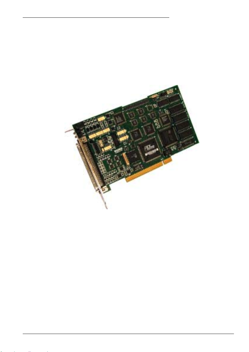
NextMove PCI
Motion Controller
Installation Manual
3/02 MN1903
Page 2

Page 3

Contents
1 General Information 1-1.................................
2 Introduction 2-1........................................
2.1 NextMove PCI features 2-1..................................
2.2 Receiving and inspection 2-3................................
2.2.1 Identifying the catalog number 2-3....................................
2.3 Units and abbreviations 2-4..................................
3 Basic Installation 3-1....................................
3.1 Introduction 3-1............................................
3.1.1 Hardware requirements 3-1.........................................
3.1.2 Tools and miscellaneous hardware 3-1................................
3.1.3 Other information needed for installation 3-1...........................
3.2 Location requirements 3-2...................................
3.3 Installation 3-3.............................................
3.3.1 Installing the NextMove PCI card 3-3.................................
3.3.2 NextMove PCI Expansion card and CAN Bracket board 3-3..............
4 Input / Output 4-1......................................
4.1 Outline 4-1................................................
4.2 100-pin edge connector 4-1..................................
4.2.1 100-pin connector pin assignment 4-2.................................
4.3 Analog I/O 4-4.............................................
4.3.1 Analog inputs - X6 4-5..............................................
4.3.2 Analog outputs (Drive Demand/Command) - X7 4-7.....................
4.4 Digital I/O 4-8..............................................
4.4.1 Digital inputs - X1 4-10..............................................
4.4.2 Digital inputs - X2 4-11..............................................
4.4.3 Digital inputs - X3 4-12..............................................
4.4.4 Digital outputs - X4 4-13.............................................
4.4.5 Digital outputs - X5 4-14.............................................
4.5 Other I/O 4-15..............................................
4.5.1 Encoder interfaces - X12, X13, X14, X15, X16 4-15......................
4.5.2 Encoder input frequency 4-16........................................
4.5.3 Power - X9 4-17....................................................
4.5.4 Relay and CAN power - X8 4-18......................................
4.5.5 Stepper drive outputs - X10, X11 4-19..................................
MN1903
Contents i
Page 4

4.6 CAN Connections 4-20.......................................
4.6.1 CAN1 (CANopen) - X17 4-21.........................................
4.6.2 CAN2 (Baldor CAN) - X18 4-22.......................................
4.7 Other I/O 4-23..............................................
4.7.1 Emulator connection 4-23............................................
4.8 Reset states 4-23...........................................
4.8.1 System watchdog 4-23..............................................
4.9 Connection summary - minimum system wiring 4-24.............
5 Operation 5-1..........................................
5.1 Introduction 5-1............................................
5.1.1 Installing the driver software - Windows 95, 98 and ME 5-1...............
5.1.2 Installing the driver software - Windows NT 5-2.........................
5.1.3 Installing the driver software - Windows 2000 5-2.......................
5.1.4 Installing WorkBench v5 5-3.........................................
5.1.5 Starting WorkBench v5 5-4..........................................
5.2 WorkBench v5 5-7..........................................
5.2.1 Help file 5-7......................................................
5.3 Configuring an axis 5-8.....................................
5.3.1 Choosing an axis - 1, 2, 3 and 4 axis cards 5-8.........................
5.3.2 Choosing an axis - 8 axis card 5-8...................................
5.3.3 Selecting a scale 5-9...............................................
5.3.4 Setting the drive enable output 5-10...................................
5.3.5 Testing the drive enable output 5-11...................................
5.4 Servo axis - testing and tuning 5-12............................
5.4.1 Testing the drive command output 5-12.................................
5.4.2 An introduction to closed loop control 5-13..............................
5.5 Servo axis - tuning for current control 5-16......................
5.5.1 Selecting servo loop gains 5-16.......................................
5.5.2 Underdamped response 5-18.........................................
5.5.3 Overdamped response 5-19..........................................
5.5.4 Critically damped response 5-20......................................
5.6 Servo axis - eliminating steady-state errors 5-21.................
5.7 Servo axis - tuning for velocity control 5-22.....................
5.7.1 Calculating KVELFF 5-22............................................
5.7.2 Adjusting KPROP 5-25..............................................
5.8 Stepper axis - testing 5-27....................................
5.8.1 Testing the drive command output 5-27.................................
5.9 Digital input/output configuration 5-28..........................
5.9.1 Digital input configuration 5-28........................................
5.9.2 Digital output configuration 5-29.......................................
5.10 Saving setup information 5-30.................................
5.10.1 Loading saved information 5-31.......................................
ii Contents
MN1903
Page 5

6 Troubleshooting 6-1....................................
6.1 Introduction 6-1............................................
6.1.1 Problem diagnosis 6-1..............................................
6.1.2 SupportMet feature 6-1............................................
6.2 NextMove PCI indicators 6-2.................................
6.2.1 Status and CAN LEDs 6-2..........................................
6.2.2 Communication 6-3................................................
6.2.3 Motor control 6-3..................................................
7 Specifications 7-1......................................
7.1 Introduction 7-1............................................
7.1.1 Mechanical specifications 7-1.......................................
7.1.2 Analog inputs (X6) 7-1..............................................
7.1.3 Analog outputs (Drive Demand/Command - X7) 7-2.....................
7.1.4 Digital inputs (X1 & X2) 7-2.........................................
7.1.5 Digital inputs (X3) 7-2..............................................
7.1.6 Digital outputs (X4) 7-3.............................................
7.1.7 Relay output (X8) 7-3..............................................
7.1.8 Encoder interfaces (X12 - X16) 7-3...................................
7.1.9 Stepper outputs (X10 & X11) 7-4.....................................
7.1.10 CANopen interface (X17) 7-4........................................
7.1.11 Baldor CAN interface (X18) 7-4......................................
Appendices
A Accessories A-1........................................
A.1 Introduction A-1............................................
A.1.1 NextMove PCI Expansion card A-1...................................
A.1.2 Axis numbering when using expansion card(s) A-2......................
A.1.3 Expansion card status LEDs A-3.....................................
A.1.4 NextMove PCI Breakout module A-4..................................
A.1.5 Digital output modules A-5..........................................
A.1.6 NextMove PC system adapter A-5....................................
A.1.7 Spares A-5.......................................................
A.1.8 Baldor CAN nodes A-6.............................................
A.1.9 NextMove PCI CAN Bracket board A-7................................
A.1.10 Encoder Splitter/Buffer board A-7.....................................
MN1903
Contents iii
Page 6

iv Contents
MN1903
Page 7

Teleph
61296745455
1 General Information
LT0166A00 Copyright Baldor (c) 2002. All rights reserved.
This manual is copyrighted and all rights are reserved. This document or attached software may not,
in whole or in part, be copied or reproduced in any form without the prior written consent of BALDOR.
BALDOR makes no representations or warranties with respect to the contents hereof and specifically
disclaims any implied warranties of fitness for any particular purpose. The information in this
document is subject to change without notice.
BALDOR assumes no responsibility for any errors that may appear in this document.
Mintt is a registered trademark of Baldor.
Windows 95, Windows 98, Windows ME, Windows NT, Windows 2000 and Windows XP are
registered trademarks of the Microsoft Corporation.
UL and cUL are registered trademarks of Underwriters Laboratories.
Limited Warranty:
For a period of two (2) years from the date of original purchase, BALDOR will repair or replace without
charge controls and accessories which our examination proves to be defective in material or
workmanship. This warranty is valid if the unit has not been tampered with by unauthorized persons,
misused, abused, or improperly installed and has been used in accordance with the instructions and/or
ratings supplied. This warranty is in lieu of any other warranty or guarantee expressed or implied.
BALDOR shall not be held responsible for any expense (including installation and removal),
inconvenience, or consequential damage, including injury to any person or property caused by items of
our manufacture or sale. (Some countries and U.S. states do not allow exclusion or limitation of
incidental or consequential damages, so the above exclusion may not apply.) In any event,
BALDOR’s total liability, under all circumstances, shall not exceed the full purchase price of the
control. Claims for purchase price refunds, repairs, or replacements must be referred to BALDOR with
all pertinent data as to the defect, the date purchased, the task performed by the control, and the
problem encountered. No liability is assumed for expendable items such as fuses. Goods may be
returned only with written notification including a BALDOR Return Authorization Number and any
return shipments must be prepaid.
1
Baldor UK Ltd
Mint Motion Centre
6 Bristol Distribution Park
Hawkley Drive
Bristol, BS32 0BF
Telephone: +44 (0) 1454 850000
Fax: +44 (0) 1454 850001
Email: technical.support@baldor.co.uk
Web site: www.baldor.co.uk
Baldor Electric Company
Telephone: +1 501 646 4711
Fax: +1 501 648 5792
Email: sales@baldor.com
Web site: www.baldor.com
Baldor ASR GmbH
Telephone: +49 (0) 89 90508-0
Fax: +49 (0) 89 90508-492
Baldor ASR AG
Telephone: +41 (0) 52 647 4700
Fax: +41 (0) 52 659 2394
Australian Baldor Pty Ltd
one: +
Fax: +61 2 9674 2495
Baldor Electric (F.E.) Pte Ltd
Telephone: +65 744 2572
Fax: +65 747 1708
Baldor Italia S.R.L
Telephone: +39 (0) 11 56 24 440
Fax: +39 (0) 11 56 25 660
General Information 1-1MN1903
Page 8
Safety Notice
Only qualified personnel should attempt the start-up procedure or troubleshoot this equipment.
This equipment may be connected to other machines that have rotating parts or parts that are
controlled by this equipment. Improper use can cause serious or fatal injury. Only qualified personnel
should attempt to start-up, program or troubleshoot this equipment.
Precautions
WARNING: Do not touch any circuit board, power device or electrical connection before you
WARNING: Be sure that you are completely familiar with the safe operation and programming
WARNING: The stop input to this equipment should not be used as the single means of
WARNING: Improper operation or programming may cause violent motion of the motor shaft
CAUTION: The safe integration of this equipment into a machine system is the responsibility
CAUTION: Electrical components can be damaged by static electricity. Use ESD
first ensure that no high voltage is present at this equipment or other equipment to
which it is connected. Electrical shock can cause serious or fatal injury. Only
qualified personnel should attempt to start-up, program or troubleshoot this
equipment.
of this equipment. This equipment may be connected to other machines that have
rotating parts or parts that are controlled by this equipment. Improper use can
cause serious or fatal injury. Only qualified personnel should attempt to program,
start-up or troubleshoot this equipment.
achieving a safety critical stop. Drive disable, motor disconnect, motor brake and
other means should be used as appropriate. Only qualified personnel should
attempt to program, start-up or troubleshoot this equipment.
and driven equipment. Be certain that unexpected motor shaft movement will not
cause injury to personnel or damage to equipment. Peak torque of several times
the rated motor torque can occur during control failure.
of the machine designer. Be sure to comply with the local safety requirements at
the place where the machine is to be used. In Europe these are the Machinery
Directive, the ElectroMagnetic Compatibility Directive and the Low Voltage
Directive. In the United States this is the National Electrical code and local codes.
(electro-static discharge) procedures when handling this drive.
1-2 General Information MN1903
Page 9
2 Introduction
2.1 NextMove PCI features
NextMove PCI is a high speed multi-axis intelligent motion controller for use in PCI bus based
PC systems.
2
NextMove PCI features the MintMT motion control language. MintMT is a structured form of
Basic, custom designed for stepper or servo motion control applications. It allows you to get
started very quickly with simple motion control programs. In addition, MintMT includes a wide
range of powerful commands for complex applications.
Standard features include:
H Control of up to eight axes
H Point to point moves, software cams and gearing
H 20 digital inputs, software configurable as level or edge triggered
H 12 digital outputs with NPN (FET) or PNP (Darlington) options available
H 4 differential analog inputs with 12-bit resolution
H CANopen protocol for peer-to-peer communications with MintMT controllers and other
third party devices
H Proprietary CAN protocol for control of Baldor remote I/O devices
H Programmable in MintMT
Introduction 2-1MN1903
Page 10

Included with NextMove PCI is the Baldor Motion Toolkit CD. This contains a number of
utilities and useful resources to get the most from you MintMT controller. These include:
H Mint WorkBench v5
This is the user interface for communicating with the NextMove PCI. Installing Mint
WorkBench will also install firmware for NextMove PCI.
H PC Developer Libraries
These include ActiveX interfaces that allow PC applications to be written that
communicate with the NextMove PCI.
H Embedded Developer Libraries
Allows embedded C31 applications to be developed using the Texas Instruments
TMS320C3x compiler.
This manual is intended to guide you through the installation of NextMove PCI.
The chapters should be read in sequence.
The Basic Installation section describes the mechanical installation of the NextMove PCI.
The following sections require knowledge of the low level input/output requirements of the
installation and an understanding of computer software installation. If you are not qualified in
these areas you should seek assistance before proceeding.
2-2 Introduction MN1903
Page 11

2.2 Receiving and inspection
When you receive your NextMove PCI, there are several things you should do immediately:
1. Check the condition of the packaging and report any damage immediately to the carrier
that delivered your NextMove PCI.
2. Remove the NextMove PCI from the shipping container but do not remove its anti-static bag
until you are ready to install it. The packing materials may be retained for future shipment.
3. Verify that the catalog number of the NextMove PCI you received is the same as the
catalog number listed on your purchase order. The catalog/part number is described in
the next section.
4. Inspect the NextMove PCI for external damage during shipment and report any damage to
the carrier that delivered it.
5. If the NextMove PCI is to be stored for several weeks before use, be sure that it is stored
in a location that conforms to the storage humidity and temperature specifications shown
in section 3.2.
2.2.1 Identifying the catalog number
NextMove PCI cards are available with different specifications. As a reminder of which card
has been installed, it is a good idea to write the catalog number in the space provided below.
Catalog number:
Installed in: ________________________
A description of the catalog numbers are shown in the following table:
Catalog
number
PCI001-501 NMPCI main card with PNP digital outputs, 1 axis
PCI001-502 NMPCI main card with PNP digital outputs, 2 axes
PCI001-503 NMPCI main card with PNP digital outputs, 3 axes
PCI001-504 NMPCI main card with PNP digital outputs, 4 axes
PCI001-505 NMPCI main card with PNP digital outputs, 8 axes
PCI001-510 NMPCI main card with NPN digital outputs, 1 axis
PCI001-511 NMPCI main card with NPN digital outputs, 2 axes
PCI001-512 NMPCI main card with NPN digital outputs, 3 axes
PCI001-508 NMPCI main card with NPN digital outputs, 4 axes
PCI001-513 NMPCI main card with NPN digital outputs, 8 axes
PCI001-_______
Description
Date: ______
Introduction 2-3MN1903
Page 12

2.3 Units and abbreviations
The following units and abbreviations may appear in this manual:
V Volt (also VAC and VDC)...............
WWatt..............
A Ampere...............
Ω Ohm...............
µF microfarad..............
pF picofarad..............
mH millihenry.............
Φ phase...............
ms millisecond..............
µs microsecond..............
ns nanosecond..............
Kbaud kilobaud (the same as Kbit/s in most applications)...........
MB megabytes.............
CDROM Compact Disc Read Only Memory.........
CTRL+E on the PC keyboard, press Ctrl then E at the same time..........
mm millimeter.............
m meter...............
in inch...............
ft feet...............
lb-in pound-inch (torque).............
Nm Newton-meter (torque).............
DAC Digital to Analog Converter............
ADC Analog to Digital Converter............
AWG American Wire Gauge............
(NC) Not Connected............
2-4 Introduction MN1903
Page 13

3 Basic Installation
3.1 Introduction
You should read all the sections in Basic Installation.
It is important that the correct steps are followed when installing the NextMove PCI.
This section describes the mechanical and electrical installation of the NextMove PCI.
3.1.1 Hardware requirements
The components you will need to complete the basic installation are described below:
H A PC that fulfills the following specification:
Minimum specification Recommended specification
Processor Intel Pentium 133MHz Intel Pentium 200MHz or faster
RAM 32MB 64MB
Hard disk space 40MB 60MB
CD-ROM ACD-ROMdrive
Screen 800 x 600, 256 colors 1024 x 768, 256 colors
Mouse A mouse or similar pointing device
Operating
system
Windows 95, Windows 98, Windows ME,
Windows NT, Windows 2000 or Windows XP
3
PCI slot One spare PCI slot
3.1.2 Tools and miscellaneous hardware
H Your PC operating system user manual might be useful if you are not familiar with Windows.
H A small cross-head screwdriver for fitting the card.
3.1.3 Other information needed for installation
You will need the following information to complete the installation:
H Knowledge of which digital inputs/outputs will be ‘Active Low’ or ‘Active High’ to meet the
requirements and specification of the system you are going to build.
Basic Installation 3-1MN1903
Page 14
3.2 Location requirements
It is essential that you read and understand this section before beginning the
installation
.
CAUTION: To prevent equipment damage, be certain that input and output signals
CAUTION: To ensure reliable performance of this equipment be certain that all
CAUTION: Avoid locating the NextMove PCI or host PC immediately above or beside
CAUTION: Avoid locating the NextMove PCI or host PC in the vicinity of corrosive
The safe operation of this equipment depends upon its use in the appropriate environment.
The following points must be considered:
H The NextMove PCI must be installed in an enclosed cabinet located so that it can only be
accessed by service personnel using tools.
H The maximum suggested operating altitude is 6560ft (2000m).
H The NextMove PCI must be installed in an ambient temperature of 32°F to 104°F
(0°C to 40°C).
H The NextMove PCI must be installed in relative humidity levels of less than 80% for
temperatures up to 87°F (31°C) decreasing linearly to 50% relative humidity at 104°F
(40°C) (non-condensing).
H The NextMove PCI must be installed where the pollution degree according to IEC664 shall
not exceed 2.
H Power is supplied to the card from the host PC power supply bus.
H The atmosphere shall not contain flammable gases or vapors.
H There shall not be abnormal levels of nuclear radiation or X-rays.
are powered and referenced correctly.
signals to/from the NextMove PCI are shielded correctly.
heat generating equipment, or directly below water steam pipes.
substances or vapors, metal particles and dust.
3-2 Basic Installation MN1903
Page 15

3.3 Installation
NextMove PCI can be installed into an AT style personal computer that has a free 7 inch PCI
card slot. The Baldor Motion Toolkit CD supports the following operating systems:
Windows 95, Windows 98, Windows ME, Windows NT4 and Windows 2000.
3.3.1 Installing the NextMove PCI card
CAUTION: Before touching the card, be sure to discharge static electricity from your
1. Exit any applications that are running and close all windows. Shutdown Windows.
2. Turn off the power (if not automatically done by Windows) and unplug all power cords.
3. Remove the cover from the computer system unit.
4. Locate an unused PCI slot.
5. Remove the backplate cover from the slot, and save the screw for later use.
6. Discharge any static electricity from your body and clothing.
7. Remove the card from its protective wrapper. Do not touch the gold contacts at the bottom
of the card.
8. Align the bottom of the card (gold contacts) with the slot and press the card firmly into the
socket. When correctly installed, the card locks into place.
9. Make sure that the top of the card is level (not slanted) and that the slot on top of the card’s
metal bracket lines up with the screw hole in the PC case.
10. Insert the screw and tighten to secure the card.
If you are also installing NextMove PCI expansion card(s) or a CAN Bracket board see section
3.3.2 before continuing with step 11.
11. Replace the computer cover and screws.
12. Reconnect any cables and power cords that were disconnected or unplugged.
body and clothing by touching a grounded metal surface. Alternatively,
wear an earth strap while handling the card.
3.3.2 NextMove PCI Expansion card and CAN Bracket board
1. Remove the backplate and install the NextMove PCI expansion card in the neighboring slot
on the component side of the main NextMove PCI card. See sections A.1.1 for details about
connections to the NextMove PCI card.
2. If you are installing a CAN Bracket board, remove the backplate from a spare PCI slot location
and install the card. See sections 4.6 and A.1.9 for details about the connections to the
NextMove PCI card.
This completes the basic installation.
You should read the following sections in
sequence before using the NextMove PCI.
Basic Installation 3-3MN1903
Page 16

3-4 Basic Installation MN1903
Page 17

4 Input / Output
4.1 Outline
This section describes the digital and analog input and output capabilities of the
NextMove PCI.
The following conventions will be used to refer to the inputs and outputs:
I/O Input / Output..............
DIN Digital Input.............
DOUT Digital Output...........
AIN Analog Input.............
AOUT Analog Output...........
Connections to the NextMove PCI card are made using the 100-pin cable assembly and DIN
rail mounted NextMove PCI Breakout module (supplied as options, see Appendix A).
All connector numbers in the following sections refer to the breakout module.
4.2 100-pin edge connector
100 50
4
51 1
The pin assignment for the 100-pin D-type connector is shown in
Table 1.
Input / Output 4-1MN1903
Page 18

4.2.1 100-pin connector pin assignment
Pin Signal Pin Signal
1 AIN0+ 51 AIN1+
2 AIN0- 52 AIN1-
3 AIN2+ 53 AIN3+
4 AIN2- 54 AIN3-
5 Demand0 55 Demand1
6 Demand2 56 Demand3
7 Analog GND 57 GND
8 GND 58 +5V out
9 CAN1 transmit 59 CAN2 transmit
10 CAN1 receive 60 CAN2 receive
11 Encoder 2 CHA- 61 Encoder 0 CHA-
12 Encoder 2 CHA+ 62 Encoder 0 CHA+
13 Encoder 2 CHB- 63 Encoder 0 CHB -
14 Encoder 2 CHB+ 64 Encoder 0 CHB+
15 Encoder 2 CHZ- 65 Encoder 0 CHZ-
16 Encoder 2 CHZ+ 66 Encoder 0 CHZ+
17 Encoder 3 CHA- 67 Encoder 1 CHA -
18 Encoder 3 CHA+ 68 Encoder 1 CHA+
19 Encoder 3 CHB- 69 Encoder 1 CHB -
20 Encoder 3 CHB+ 70 Encoder 1 CHB+
21 Encoder 3 CHZ- 71 Encoder 1 CHZ-
22 Encoder 3 CHZ+ 72 Encoder 1 CHZ+
23 Master encoder CHA- 73 Master encoder CHB-
24 Master encoder CHA+ 74 Master encoder CHB+
25 Master encoder CHZ- 75 Master encoder CHZ+
26 Step Output 0 76 +5V out
27 Step Output 2 77 Direction Output 0
28 Step Output 1 78 Direction Output 2
4-2 Input / Output MN1903
Page 19

Pin SignalPinSignal
29 Direction Output 1 79 Direction Output 3
30 Step Output 3 80 DOUT11
31 DOUT10 81 USR V+
32 DOUT9 82 DOUT8
33 DOUT7 83 USR V+
34 DOUT6 84 DOUT5
35 DOUT4 85 CGND
36 DOUT3 86 DOUT2
37 DOUT1 87 CGND
38 DOUT0 88 Common2
39 DIN19 89 DIN17
40 DIN18 90 DIN16
41 DIN15 91 DIN13
42 DIN14 92 DIN12
43 DIN11 93 DIN9
44 DIN10 94 DIN8
45 DIN7 95 DIN5
46 DIN6 96 DIN4
47 DIN3 97 DIN1
48 DIN2 98 DIN0
49 Common1 99 Relay NC
50 Relay COM 100 Relay NO
Table 1 - 100-pin connector pin assignment
Input / Output 4-3MN1903
Page 20

4.3 Analog I/O
The NextMove PCI provides:
H Four 12-bit resolution analog inputs.
The inputs are available on connector X6 on the NextMove PCI Breakout module.
H Four 14-bit resolution analog outputs.
The outputs are available on connector X7 on the NextMove PCI Breakout module.
Sections 4.3.1 to 4.3.2 describe each analog input and output.
4-4 Input / Output MN1903
Page 21
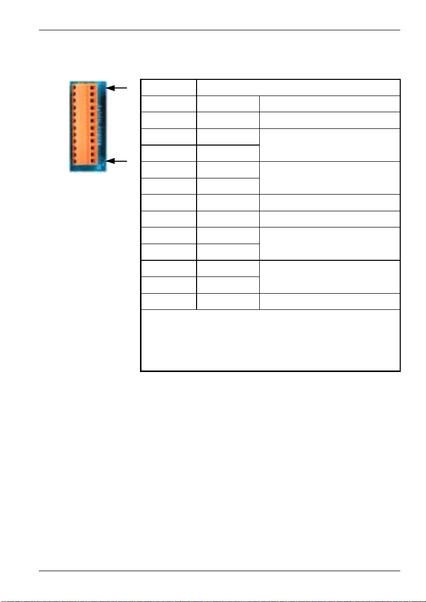
4.3.1 Analog inputs - X6
A
A
A
A
12
1
Description
Single ended or differential inputs
Voltage range: software selectable 0-5V, ±5V, 0-10V, ±10V
Resolution: 12-bit with sign (accuracy ±4.9mV @ ±10V input)
Input impedance: >5kΩ
Sampling frequency: 2.5kHz
Location Breakout module, connector X6
Pin Name MintMT keyword / description
1 AGND Analog ground
2 AIN0+
3 AIN0-
4 AIN1+
5 AIN1-
6 Shield Shield connection
7 AGND Analog ground
8 AIN2+
9 AIN2-
10 AIN3+
11 AIN3-
12 Shield Shield connection
IN0
IN1
IN2
IN3
Shielded twisted pairs should be used and connected as shown in Figure 1. The shield
connection should be made at one end only. The analog inputs pass through a differential
buffer and second order Butterworth filter with a cut-off frequency of 1kHz. Both the filtered
and unfiltered signals are converted using a multiplexed 12-bit ADC. This has four input
voltage ranges that can be selected in MintMT using the ADCMODE keyword.
Input / Output 4-5MN1903
Page 22
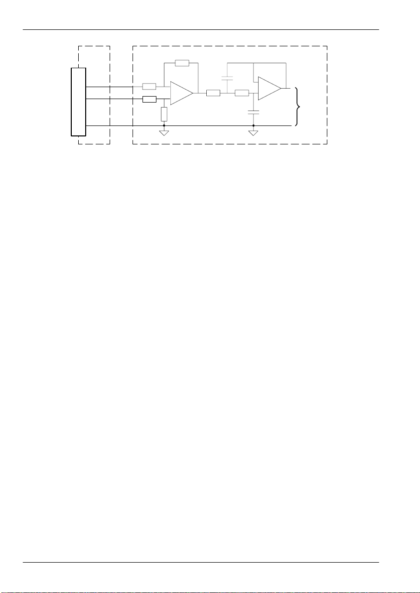
AIN0-
AGND
Breakout
module
X6
3
2
1
NextMove PCI
100
pin
cable -
-
+AIN0+
+
MintMT
ADC.0
Figure 1 - Analog input wiring, AIN0 shown
For differential inputs connect input lines to AIN+ and AIN-. Leave AGND unconnected.
For single ended inputs, connect signal to AIN+. Connect signal ground to AIN- and AGND.
4-6 Input / Output MN1903
Page 23
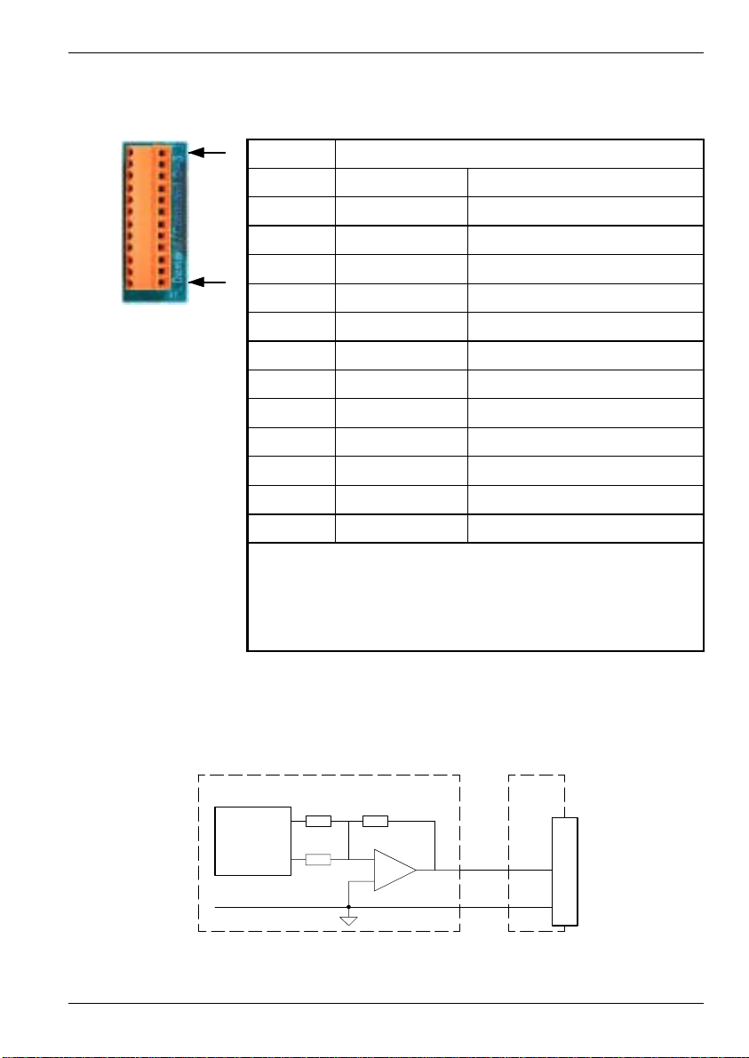
4.3.2 Analog outputs (Drive Demand/Command) - X7
Location Breakout module, connector X7
12
Pin Name Description
1 Demand0 Demand output signal for axis 0
2 AGND Analog ground
1
Description
Four independent command outputs
Output range: ±10VDC (±0.1%).
Resolution: 14-bit (accuracy ±1.22mV).
Output current: 1mA maximum
Update frequency: Immediate
3 Shield Shield connection
4 Demand1 Demand output signal for axis 1
5 AGND Analog ground
6 Shield Shield connection
7 Demand2 Demand output signal for axis 2
8 AGND Analog ground
9 Shield Shield connection
10 Demand Demand output signal for axis 3
11 AGND Analog ground
12 Shield Shield connection
MintMT and the Mint Motion Library use the analog outputs to control servo drives.
Demand / Command outputs 0 to 3 correspond to axes 0 to 3. The analog outputs may be
used to drive loads of 10kΩ or greater. The outputs are referenced to PC system ground.
Shielded twisted pair cable should be used. The shield connection should be made at one end
only.
NextMove PCI
Demand
±100%
10k 10k
160k
-
+
100
pin
cable
Breakout
module
X7
1
2
Demand0
AGND
Figure 2 - Analog output circuit - Demand0 shown
Input / Output 4-7MN1903
Page 24

4.4 Digital I/O
X
3-Fast
itioni
C
1
X
C
2
X
1-G
There are a total of 20 general purpose digital inputs. Inputs can be configured in MintMT for
any of the following functions:
H forward limit (end of travel) input on any axis
H reverse limit (end of travel) input on any axis
H home input on any axis
H drive error input on any axis.
The inputs use two separate common connections. This can be useful for separating inputs
which are active low from others which are active high. If all inputs are similar then the
commons can be connected together to form one common connection. The arrangement of
the inputs, their common power connection and the connectors on which they are available
are described in Table 2 :
Common Breakout module connector
Input
DIN0
DIN1
DIN2
DIN3
DIN4
DIN5
DIN6
DIN7
DIN8
DIN9
DIN10
DIN11
DIN12
DIN13
DIN14
DIN15
DIN16
DIN17
DIN18
DIN19
ommon
ommon
pos
2 - General purpose inputs
eneralpurposeinputs
nputs
Table 2 - Digital input arrangement
4-8 Input / Output MN1903
Page 25

Inputs can be shared between axes, and are programmable in MintMT (using the keywords
INPUTACTIVELEVEL, INPUTMODE, INPUTPOSTRIGGER and INPUTNEGTRIGGER)to
determine their active level and if they should be edge triggered. Four of the inputs,
DIN0-DIN3, are fast position latch inputs.
There are a total of 12 general purpose digital outputs. An output can be configured in MintMT
as a general purpose output, a drive enable output or a general error output. Outputs can be
shared between axes and are programmable, using the MintMT keyword
OUTPUTACTIVELEVEL, to determine their active level.
The outputs are driven by a module fitted to the NextMove PCI card. Two module types are
available:
H Current sourcing, PNP Darlington with overcurrent and short circuit protection
(OPT025-507, fitted as standard).
H Current sinking, open drain N -channel MOSFET (OPT025-508).
If further digital outputs are required, an expansion card is recommended (see section A.1.1).
If an expansion card is not available, unused stepper axes can be configured as Off, and their
direction and pulse output pins then used as outputs. See the MintMT keywords CONFIG and
STEPPERIO.
Input / Output 4-9MN1903
Page 26
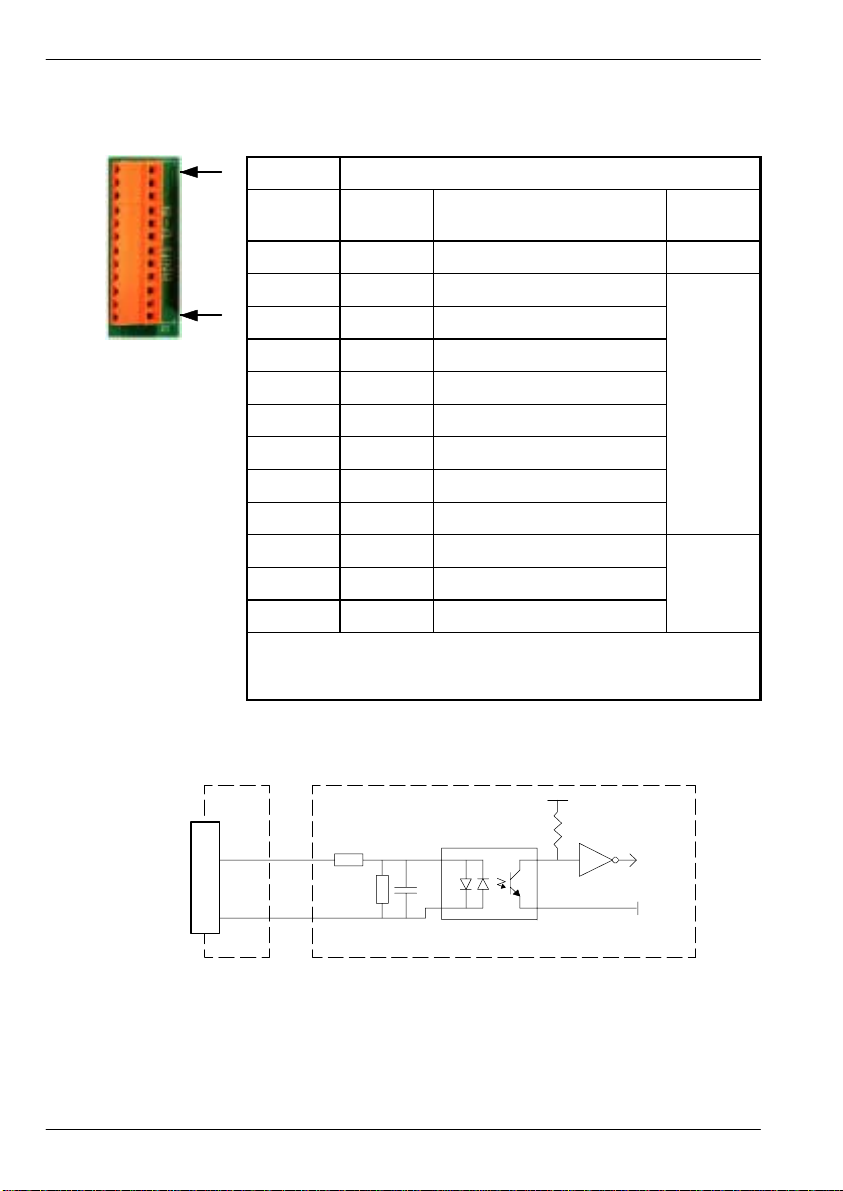
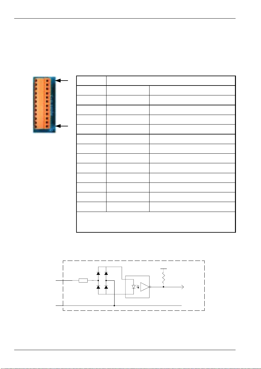
4.4.1 Digital inputs - X1
C
2
12
1
Description
Eight general purpose optically isolated AC digital inputs.
Sampling frequency: 1kHz
Location Breakout module, connector X1
Pin Name MintMT keyword /
description
1 Shield Shield connection
2 DIN12 INX.12
3 DIN13 INX.13
4 DIN14 INX.14
5 DIN15 INX.15
6 DIN16 INX.16
7 DIN17 INX.17
8 DIN18 INX.18
9 DIN19 INX.19
10 Shield Shield connection
11 - (NC)
12 Common2 Common connection
Common
ommon
100
pin
cable
NextMove PCI
Vcc
Active low:
DINx =0V
Common2 = 12-24VDC (±20%)
DIN12
Common2
Breakout
module
X1
2
12
Active high:
DINx = 12-24VDC (±20%)
Common2 =0V
Figure 3 - Digital input circuit - DIN12 shown
4-10 Input / Output MN1903
MintMT
INX.12
DGND
Page 27
The inputs are conditioned using low pass RC filters and Schmitt trigger buffers. If an input is
C
1
C
2
configured as edge triggered, the triggering pulse must have a duration of at least 1ms (one
software scan) to guarantee acceptance by MintMT. Voltages below 2V are considered as 0V.
The use of shielded cable for inputs is recommended.
Active high: The digital inputs will be active when a voltage of +24VDC (±20%) is applied to
them and will sink a maximum of 8mA each.
Active low: The digital inputs will be active when grounded (<2V) and will source a maximum
of 8mA each.
Note: Sustained input voltages above 28V will damage the inputs.
4.4.2 Digital inputs - X2
Location Breakout module, connector X2
12
Pin Name MintMT keyword /
1 Shield Shield connection
2 DIN4 INX.4
1
Description
Eight general purpose optically isolated AC digital inputs.
3 DIN5 INX.5
4 DIN6 INX.6
5 DIN7 INX.7
6 DIN8 INX.8
7 DIN9 INX.9
8 DIN10 INX.10
9 DIN11 INX.11
10 Shield Shield connection
11 Common1 Common connection
12 Common2 Common connection
description
Common
ommon
ommon
The inputs are electrically identical to inputs DIN12 to DIN19 described in section 4.4.1.
Input / Output 4-11MN1903
Page 28
4.4.3 Digital inputs - X3
Digital inputs DIN0 to DIN3 can be used as high speed position latches. The fast position
inputs are routed through a programmable cross-point switch which allows any input to cause
the position of any combination of axes to be captured (by the hardware) within 1µs. Special
MintMT keywords (beginning with the letters FAST...) allow specific functions to be performed
as a result of fast position inputs becoming active.
12
Location
Breakout module, connector X3
Pin Name MintMT keyword / description
1 DIN0 INX.0
2 Common1 Common connection
3 Shield Shield connection
1
4 DIN1 INX.1
5 Common1 Common connection
6 Shield Shield connection
7 DIN2 INX.2
8 Common1 Common connection
9 Shield Shield connection
10 DIN3 INX.3
11 Common1 Common connection
12 Shield Shield connection
Description
Four fast position digital inputs.
Sampling frequency: 1kHz (MintMT)
Note: Digital inputs DIN0 to DIN3 are particularly sensitive to noise, so inputs must use
shielded twisted pair cable.
DINx
Common1
NextMove PCI
3k3
Active high:
DINx = 12-24VDC (±20%)
Common1 =0V
TLP115
Active low:
DINx =0V
Common1 = 12-24VDC (±20%)
Vcc
MintMT
Figure 4 - Digital input circuit - fast interrupts
4-12 Input / Output MN1903
Page 29

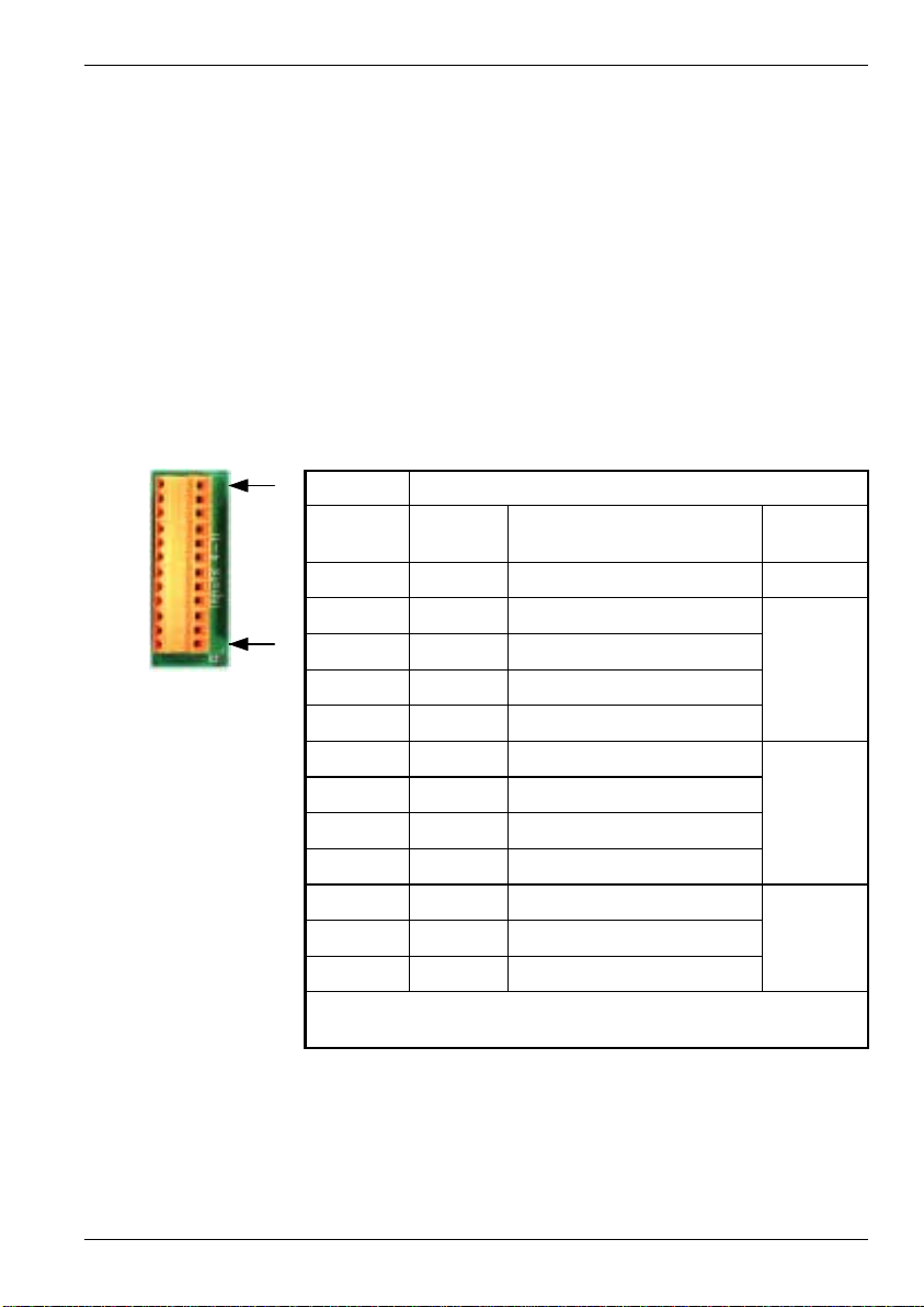
4.4.4 Digital outputs - X4
Location Breakout module, connector X4
12
1
Description
Six general purpose optically isolated digital outputs.
Output current: 50mA maximum each output
Update frequency: Immediate
Pin Name MintMT keyword / description
1 Shield Shield connection
2 DOUT6 OUTX.6
3 DOUT7 OUTX.7
4 DOUT8 OUTX.8
5 DOUT9 OUTX.9
6 DOUT10 OUTX.10
7 DOUT11 OUTX.11
8 - (NC )
9 - (NC)
10 Shield Shield connection
11 USR V+ Customer power supply
12 CGND Customer power supply ground
Each optically isolated output is designed to source current from the customer supplied
12-24V supply (USR V+) as shown in Figure 5. The use of shielded cable is recommended.
The CGND must be connected to the host PC’s GND. See section 4.5.3 for details about
connecting the USR V+ supply.
DOUT6
USR V+
Output
load
CGND
NextMove PCI
OUTX.6
Output
module
100
pin
cable
Breakout
module
X4
11
2
12
Figure 5 - Digital output circuit with standard ‘PNP’ current sourcing module - DOUT6 shown
Input / Output 4-13MN1903
Page 30

NextMove PCI
OUTX.6
Output module
100
pin
cable
Breakout
module
USR V+
X4
11
Output
load
2
DOUT6
12
CGND
Figure 6 - Digital output circuit with optional ‘NPN’ current sinking module - DOUT6 shown
4.4.5 Digital outputs - X5
Location Breakout module, connector X5
12
Pin Name MintMT keyword / description
1 Shield Shield connection
2 DOUT0 OUTX.0
1
Description
Six general purpose optically isolated digital outputs.
3 DOUT1 OUTX.1
4 DOUT2 OUTX.2
5 DOUT3 OUTX.3
6 DOUT4 OUTX.4
7 DOUT5 OUTX.5
8 - (NC )
9 - (NC)
10 Shield Shield connection
11 USR V+ Customer power supply
12 CGND Customer power supply ground
The outputs are electrically identical to outputs DOUT6 to DOUT11 described in section 4.4.4.
4-14 Input / Output MN1903
Page 31

4.5 Other I/O
4.5.1 Encoder interfaces - X12, X13, X14, X15, X16
Location Breakout module, connectors X12, X13, X14, X15, X16
Pin Name Description
1 Encoder V+ Power supply to encoder
15
69
Description
Five identical encoder inputs, each with complementary A, B and Z
channel inputs on a 9-pin female D-type connector
Up to five incremental encoders may be connected to NextMove PCI. Each input channel
uses a MAX3095 differential line receiver with pull up resistors and terminators. Encoders
must provide either 5V differential signals or RS422/RS485 differential signals. The maximum
input frequency is 7.5 million quadrature counts per second. This is equivalent to a maximum
frequency for the A and B signals of 1.87MHz. The shell of the connector is connected to
pin 4. The use of individually shielded twisted pair cable is recommended. See section 4.5.3
for details of the encoder power supply.
2 CHZ+ Index channel signal
3 CHB- Channel B signal complement
4 Shield Shield connection
5 CHA+ Channel A signal
6 CHZ- Index channel signal complement
7 GND Power supply ground
8 CHB Channel B signal
9 CHA- Channel A signal complement
100
pin
cable
NextMove PCI
10R
10R
150R 3k3
Vcc
3k3
MAX3095
CHA+
CHA-
X12
5
9
Breakout
module
Figure 7 - Encoder channel input circuit - Encoder C, Channel A shown
Input / Output 4-15MN1903
Encoder
input
circuit
Page 32

4.5.2 Encoder input frequency
F
y
The maximum encoder input frequency is affected by the length of the encoder cables.
The theoretical maximum frequency is 7.5 million quadrature counts per second. This is
equivalent to a maximum frequency for the A and B signals of 1.87MHz. However, the effect of
cable length is shown in Table 3:
requenc
1.3MHz 2 6.56
500kHz 10 32.8
250kHz 20 65.6
100kHz 50 164.0
50kHz 100 328.1
20kHz 300 984.2
10kHz 700 2296.6
7kHz 1000 3280.8
Table 3 - Effect of cable length on maximum encoder frequency
The maximum recommended cable length is 30.5m (100ft).
meters feet
Maximum cable length
4-16 Input / Output MN1903
Page 33
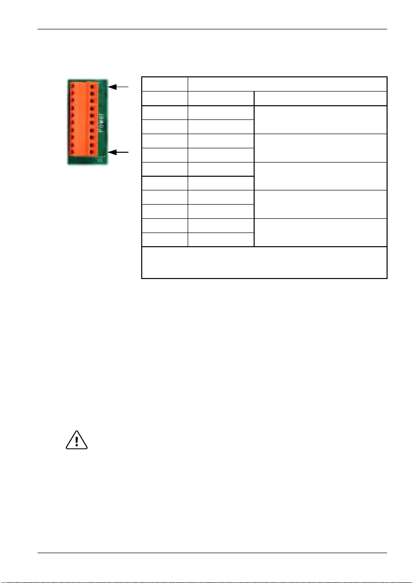
4.5.3 Power - X9
5
V
l
y
t
hehostPC
P
t
h
D
igi
tal
d
f
t
hehostPC
Cust
l
y
Cust
l
y
d
Location Breakout module, connector X9
10
Pin Name Description
1 Vcc
2 Vcc
3 Encoder V+
1
Description
Connection point for customer power supply USR V+.
Also used to route power to encoders.
The power connector X9 provides a single connection point for external power supplies.
Access is also provided to the host PC’s 5V supply. Each connection is assigned two pins on
X9 to provide increased wiring capacity. Use wire links to connect power as required.
The Encoder V+ and GND connections on X9 are connected internally to the Encoder V+ and
GND pins on connectors X12 to X16. The host PC’s +5V supply can be use to power the
encoders by connecting pin 1 or 2 to pin 3 or 4. A link is provided for this purpose. The total
current requirement of the encoders must not exceed 500mA. Check that the PC’s power
supply is capable of supplying this extra current.
4 Encoder V+
5 GND
6 GND
7 USR V+
8 USR V+
9 CGND
10 CGND
+
supp
owerto
groun
omer power supp
omer power supp
sourcefrom
e encoder connectors
rom
groun
Alternatively, a further external supply (or the USR V+ supply, see below) can be connected to
pins 3 or 4. (Remove any existing link to pin 1 or 2 before connecting an external supply). This
supply must not exceed the PCB track rating of the breakout module which is 3A at 30V.
Check that the encoders have a suitable voltage rating before connecting them to USR V+ or
other external supply.
CAUTION: Encoder power must be connected before operating the system. If the
The customer supplied USR V+ is used as the supply for the digital outputs (see sections
4.4.4 and 4.4.5). The USR V+ and CGND connections on connector X9 are connected
internally to the USR V+ and CGND pins on connectors X4, X5 and X8.
Note: The CGND (pin 9 or 10) must be connected to the host PC’s GND (pin 5 or 6).
encoders are not powered when the system is enabled, there will be no
position feedback which could cause violent motion of the motor shaft.
Input / Output 4-17MN1903
Page 34
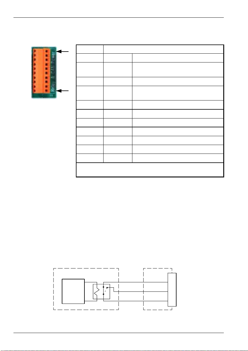
4.5.4 Relay and CAN power - X8
Location Breakout module, connector X8
10
1
The CANopen (CAN1) channel is isolated and requires a 12-24V, 60mA supply (pins 1 and 2).
These pins are connected internally to pins 9 and 3 of connector X17 (see section 4.6.1).
The Baldor CAN channel (CAN2) is normally non-isolated and therefore does not need a
power supply. However, it may be necessary for some Baldor CAN nodes to derive a 12-24V
supply from the CAN cable. For this reason, X8 provides a convenient connection point for the
supply (pins 3 and 4). These pins are connected internally to pins 5 and 4 of connector X18
(see section 4.6.2).
Pin Name Description
1 CAN1 V+ Power input for CAN1 (CANopen)
network (12-24V)
2 CAN1 GND Ground for CAN1 (CANopen) network
3 CAN2 V+ Power input for CAN2 (Baldor CAN)
network (12-24V)
4 CAN2 GND Ground for CAN2 (Baldor CAN) network
5 Relay NC Normally closed relay connection
6 Relay NO Normally open relay connection
7 Relay COM Common relay connection
8 USR V+ Customer power supply
9 CGND Customer power supply ground
10 Shield Shield connection
Description
Connection point for CAN power supply and relay contacts.
The relay pins are isolated from any internal circuits on the NextMove PCI. The relay is
controlled by a latch, which is cleared when the NextMove PCI resets. Reset can occur due to
power-down, a watchdog error or when deliberately caused by the host PC. In normal
operation the Relay NC contact is connected to Relay COM. The relay is energized in normal
use and is the factory preset global error output channel. In the event of an error or power loss
to the card, the relay is de-energized and the Relay NO contact is connected to Relay
common.
NextMove PCI Breakout
MintMT
Relay
100-pin
cable
module
X8
5
6
7
Relay NC
Relay NO
Relay COM
Figure 8 - Relay connections
4-18 Input / Output MN1903
Page 35

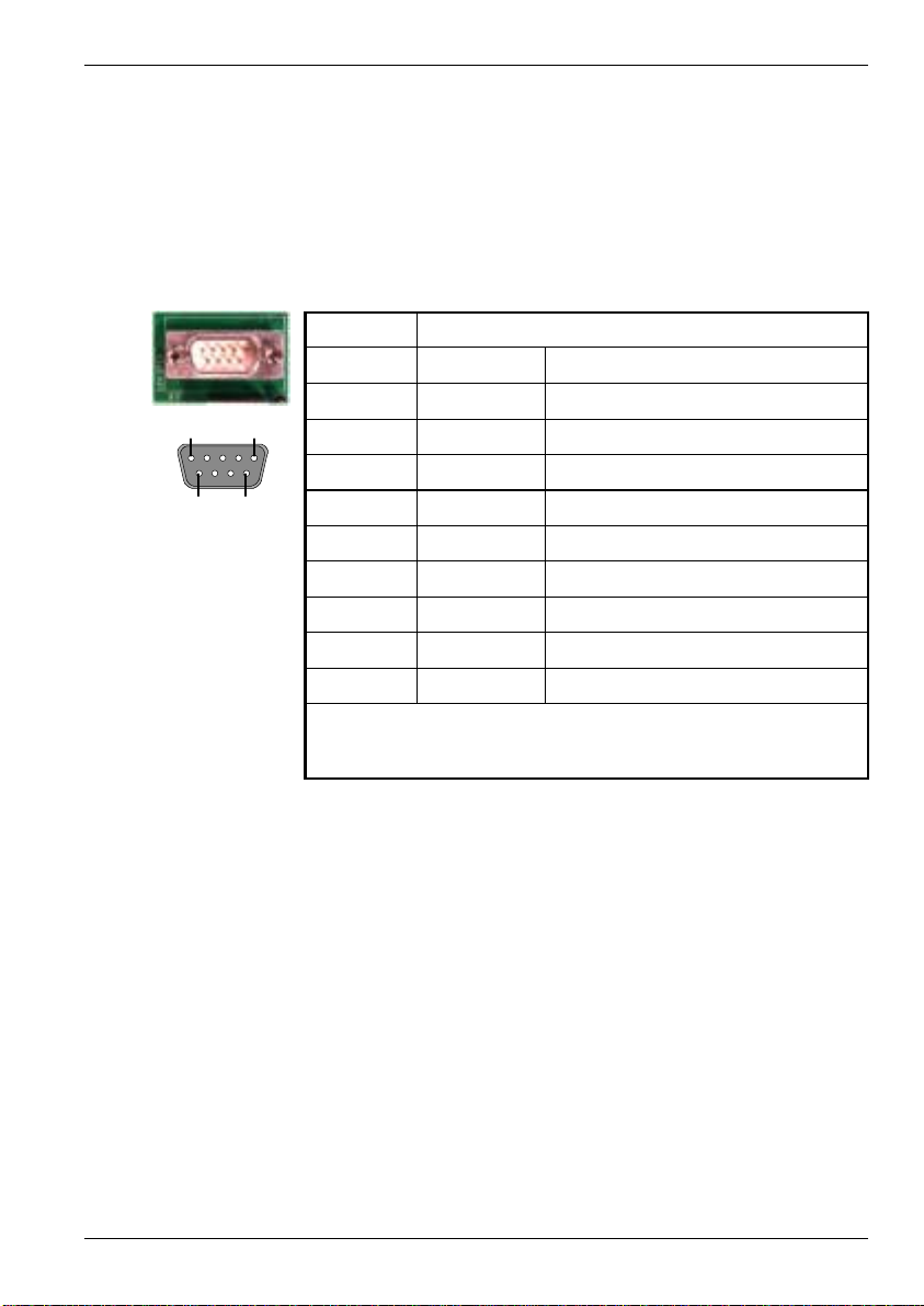
4.5.5 Stepper drive outputs - X10, X11
Location Connectors X10, X11
Pin X10 Name X11 Name Description
1 Step0+ Step2+ Step signal
2 Dir0+ Dir2+ Direction signal
1 5
6 9
Description
Four sets of stepper motor control outputs available on two 9-pin female
D-type connectors
The stepper drive outputs can operate at up to 3MHz. The signals from the NextMove PCI are
at TTL levels but are converted to 5V differential drive signals by a circuit board mounted on
the breakout module. The 9-pin D -type connectors provide 360° shielding when using high
step rates. The outputs can be connected directly to drives with single ended logic inputs by
connecting the complement of the differential signal to the drive ground. The outputs may be
programmed in MintMT for the following functions:
3 GND GND Signal ground
4 Dir1+ Dir3+ Direction signal
5 Step1+ Step3+ Step signal
6 Step0- Step2- Step signal complement
7 Dir0- Dir2- Direction signal complement
8 Dir1- Dir3- Direction signal complement
9 Step1- Step3- Step signal complement
H Step and direction for driving stepper motor drives.
H Digital outputs for general purpose use. See the MintMT keyword STEPPERIO for details.
Input / Output 4-19MN1903
Page 36
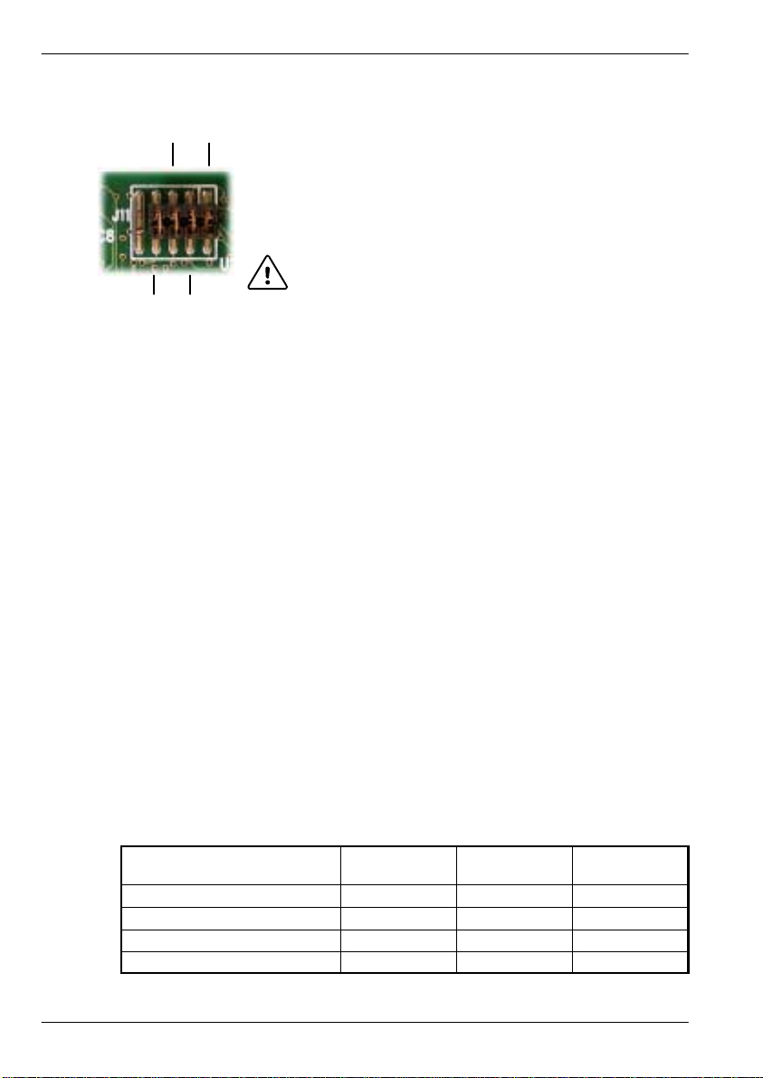
4.6 CAN Connections
CAN (Controller Area Network) is a 1Mb/s local area network.
1&2
5&6
Two CAN channels are supported by NextMove PCI - CANopen and
Baldor CAN. Access to both channels is configured by a 10-pin 2mm
pin header, J11, mounted along the top edge of the NextMove PCI
card. Jumpers link pin pairs 1 and 2, 3 and 4, 5 and 6, 7 and 8.
These jumpers route the CAN signals to the breakout module and
only need to be removed if you are connecting a CAN Bracket card.
CAUTION: Pins 9 and 10 must NOT be connected
3&47&8
together. Doing so will short-circuit the PC’s
5V power supply.
The NextMove PCI can communicate with I/O expansion modules or other MintMT controllers
via CAN, and is compatible with DS-301, version 4 (Application Layer and Communication
Profile) and mandatory sections of DS -401, version 2 (Device Profile for Generic I/O modules).
Some parts of DS-403, version 1 (Device Profile for Human Machine Interfaces)arealso
supported. When connecting third party devices please contact Baldor if you are unsure about
compatibility.
CAN offers serial communications over a two wire twisted pair cable up to a maximum of
500m (1640ft) in length, and offers very high communication reliability in an industrial
environment; the probability of an undetected error is 4.7x10
-11
. The default transmission rate
is 125Kbit/s although higher rates up to 1000Kbit/s can be selected. CAN is optimized for the
transmission of small data packets and therefore offers fast update of I/O devices (peripheral
devices) connected to the bus.
Up to 63 mixed type Baldor CAN peripherals may be connected to the NextMove PCI Baldor
CAN network using the CAL protocol, with the limitation that only 4 enabled keypads are
allowed at one time. In addition, a number of CANopen nodes can be connected
simultaneously to the CANopen network.
Terminators are provided on the breakout module for each CAN channel. These are connected
by jumpers J7 (Baldor CAN) and J8 (CANopen).
A very low error rate over CAN can only be achieved with a suitable wiring scheme, so the
following points should be observed:
H CAN must be connected via twisted pair cabling to reduce RF emissions and provide
immunity to conducted interference. The connection arrangement is normally a simple
multi-point drop. The CAN cables should have a characteristic impedance of 120Ω and a
delay of 5ns/m. Other characteristics depend upon the length of the cabling:
Cable length
0m ~ 40m (0ft ~ 131ft) 1000Kbit/s <70mΩ/m 0.25 ~ 0.34mm
40m ~ 300m (131ft ~ 984ft) 500Kbit/s <60mΩ/m 0.34 ~ 0.60mm
300m ~ 600m (984ft ~ 1968ft) 100Kbit/s <40mΩ/m 0.50 ~ 0.60mm
600m ~ 1000m (1968ft ~ 3280ft) 50Kbit/s <26mΩ/m 0.75 ~ 0.80mm
Maximum bit
rate
Resistance Conductor
area
2
2
2
2
4-20 Input / Output MN1903
Page 37
H T erminators must only be fitted at both ends of the network, not at intermediate nodes.
H The 0V connection of all of the nodes on the network must be tied together through the
CAN cabling. This ensures that the CAN signal levels transmitted by NextMove PCI or
CAN peripheral devices are within the common mode range of the receiver circuitry of
other nodes on the network.
4.6.1 CAN1 (CANopen) - X17
CANopen connections are made using the breakout module connector X17.
Location
1 5
6 9
Description
CANopen interface using a 9-pin male D -type connector with CiA
standard DS102 pin configuration
If NextMove PCI is at the end of the CANopen network the termination resistor must be
connected by fitting the termination jumper J8, labelled “CO Term”, on the breakout module.
Breakout module, connector X17
Pin Name Description
1 Shield Cable shield
2 CAN1- CAN channel 1 negative
3 CAN1 GND CAN1 Ground / earth reference
4 - (NC)
5 - (NC)
6 - (NC)
7 CAN1+ CAN channel 1 positive
8 - (NC)
9 CAN1 V+ CAN1 power (12-24V)
Input / Output 4-21MN1903
Page 38
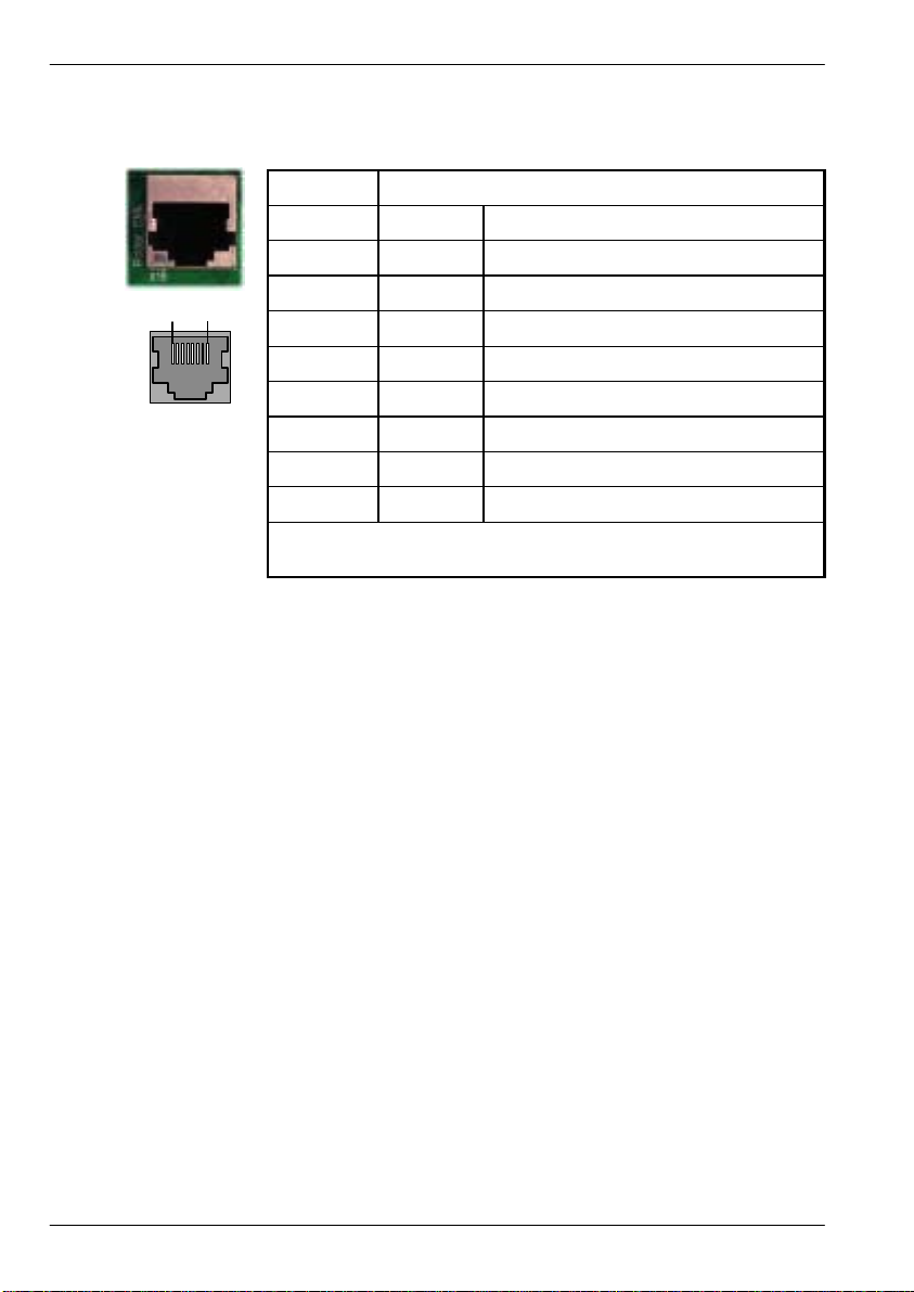
4.6.2 CAN2 (Baldor CAN) - X18
Baldor CAN connections are made using the breakout module connector X18.
Location
1 8
Description
Baldor proprietary CAN interface using a RJ45 connector.
If NextMove PCI is at the end of the Baldor CAN network a termination resistor must be
connected by fitting the termination jumper J7, labelled “BC Term”, on the breakout module.
Breakout module, connector X18
Pin Name Description
1 - (NC)
2 - (NC)
3 - (NC)
4 CAN2 0V Ground/earth reference for CAN signal
5 CAN2 V+ CAN remote node power V+ (12-24V)
6 - (NC)
7 CAN2+ CAN channel 2 positive
8 CAN2- CAN channel 2 negative
4-22 Input / Output MN1903
Page 39

4.7 Other I/O
4.7.1 Emulator connection
An 11-pin footprint on the rear of the card marked ‘ICE’ provides access to the processor for
boundary scan emulation. To connect the Texas Instruments emulator pod, a two row 12-pin
0.1in pitch surface mount pin header with pin 8 missing must be fitted. The connections are
those specified by Texas Instruments. See the ‘MintMT Embedded Programming Guide’ for
details on emulator based system debugging.
4.8 Reset states
During power up, NextMove PCI is held in a safe non-operational state known as hardware
reset. It will also go into hardware reset if the 5V supply drops below approximately 4.75V, to
prevent uncontrolled operation due to the electronics losing power. When NextMove PCI is in
hardware reset for any reason, most of the controlled interfaces fall into known states. It is
also possible for NextMove PCI to be in a state known as software reset. This is a safe
operational state where only the bootloader firmware present on NextMove PCI is running.
Hardware and software reset states should not be confused with the Mint keyword RESET
whichisusedtoclearaxiserrors.
Communications
At power up the CAN controllers will be held in reset and will have no effect on the CAN
buses. If a reset occurs during the transmission of a message CAN errors are likely to occur.
Dual Port RAM (DPR) will contain no information at power up but will be accessible by the PC.
A reset during operation will cause the DPR to stay in its current state.
Digital Outputs
All of the digital outputs are inactive on power up regardless of their polarity. They will return
to the inactive state whenever a reset occurs.
Analog Outputs
All analog outputs are set to 0V by hardware during power-up and will return to 0V on a reset.
Stepper/Encoder ASICs
The stepper/encoder ASICs will not generate stepper pulses or register any encoder input
during reset. If the unit goes into reset all position data will be lost.
4.8.1 System watchdog
The system watchdog provides hardware protection in the event of a firmware or embedded
‘C’ program malfunction. If the system watchdog is not updated, the controller is put into the
software reset state. It may be disabled during embedded code development and debugging.
Input / Output 4-23MN1903
Page 40
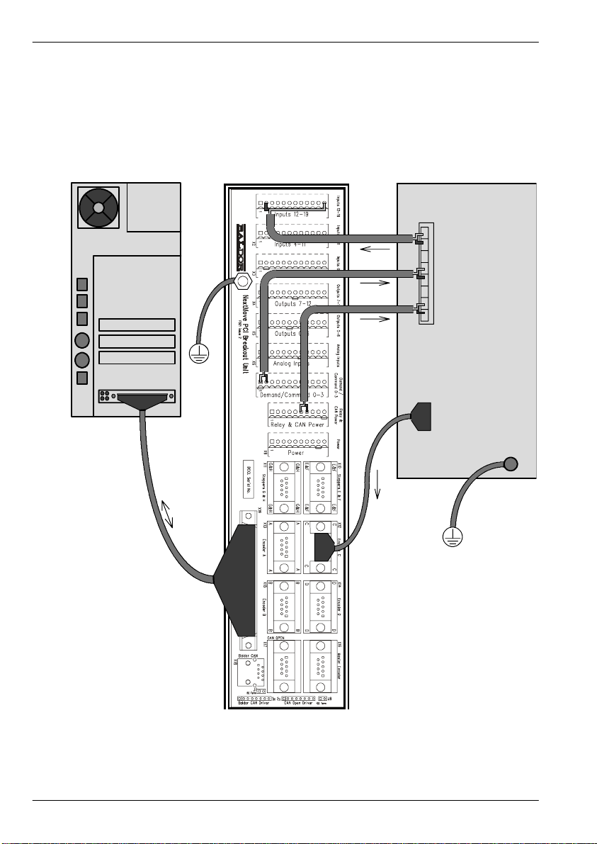
4.9 Connection su mmary - minimum system wiring
As a guide, Figure 9 shows an example of the typical minimum wiring required to allow the
NextMove PCI and a single axis servo amplifier (motor drive) to work together. Details of the
connector pins are shown in Table 4.
Host PC Breakout module Servo amplifier (axis 0)
X1
Error out
Demand +
Demand -
Enable*
Gnd*
NextMove PCI
100-pin
connecting
cable
X7
X8
X12
*Note:
This diagram shows the relay contacts
being us ed as a switch across the servo
amplifier’s enable input.
If the servo amplifier requires a 24V
enable signal then:
- Connect Gnd to CGND (X8 pin 9).
- Connect Enable to one side of the relay
(X8 pin 5 for normally clos ed operation).
- Connect the other side of the relay (X8
pin7)toUSRV+(X8pin8).
Figure 9 - Example minimum system wiring
Encoder output
from drive or
motor
4-24 Input / Output MN1903
Page 41

The pin connections in the example are described below:
C
l
f
x
is0
E
t
E
t
Breakout
module
connector
Table 4 - Connector details for minimum system wiring shown in Figure 9
Pin Name of
signal
X7 1 Demand0
2 AGND
X12 - Encoder Position feedback Encoder out
X1 2 DIN12
12 Common2
X8 7 Relay COM Common connection of relay Enable input
6 Relay NO Normally open connection
Function Connection on drive
ommandsigna
rrorinpu
of relay
or a
(Note: drive may be
labelled differently)
Demand+ input
Demand- input
(or direct from motor)
rror outpu
Amplifier/Digital
Ground
This completes the input/output wiring.
You should read the following sections in
sequence before using the NextMove PCI.
Input / Output 4-25MN1903
Page 42

4-26 Input / Output MN1903
Page 43

5 Operation
5.1 Introduction
The software provided includes a number of applications and utilities to allow you to configure,
tune and program the NextMove PCI. If you do not have experience of software installation or
Windows applications you will need to seek further assistance for this stage of the installation.
The CDROM containing the software can be found inside the rear cover of this manual or
separately within the packaging.
5.1.1 Installing the driver software - Windows 95, 98 and ME
1. Turn on the PC. During the start process, Windows will detect the newly installed
NextMove PCI card.
5
2. When the Update Device Driver wizard is displayed, place the Baldor Motion Toolkit CD
into the CDROM drive.
3. Click Next and then locate the folder containing the device driver for NextMove PCI.
This is on the CD in the folder:
Drivers\nmPCI\win9x
Follow the instructions on screen to load the device driver. Once the device driver has been
installed from the CD, Windows will continue starting as normal.
Operation 5-1MN1903
Page 44

5.1.2 Installing the driver software - Windows NT
Windows NT does not support ‘plug and play’ so there will be no indication that a new card
has been installed. The device driver for NextMove PCI must be installed from the Baldor
Motion Toolkit CD.
1. Place the Baldor Motion Toolkit CD into the CDROM drive. The CD should auto-run and
display the opening page. If auto-run is disabled, browse the CD and double click the file
SETUP.HTM.
2. Go to the NextMove PCI area and select the NextMove PCI NT Device Driver option.
Once the device driver has been installed, shut down all applications and restart the PC.
The device driver will now be loaded automatically each time Windows is started.
Note: If you are upgrading your device driver from a previous release, you must first
uninstall the old device driver. To do this, go to the Windows Control Panel, select
‘Add/Remove Programs’ and then select ‘NextMove PCI Device Driver’ from the
list.
On the CD, the Windows NT driver is located in the folder Drivers\nmPCI\winnt.
5.1.3 Installing the driver software - Windows 2000
The Windows NT device driver is used with Windows 2000, but is installed differently.
1. After installing the NextMove PCI card, turn on the PC.
2. Enter the BIOS and disable the ‘Plug and Play’ option or select ‘Operating system is not
plug and play compatible’. Exit the BIOS and allow Windows 2000 to boot normally. When
Windows 2000 has loaded it will enter the Hardware Wizard.
3. Select ‘Search for a suitable device driver’, and click Next.
4. Remove the checks from all the search locations, and click Next.
5. Select the ‘Disable the device’ option, and click Finish.
6. Restart the PC. The hardware wizard should not appear this time.
7. The Windows NT device driver can now be loaded. Place the Baldor Motion Toolkit CD
into the CDROM drive. The CD should auto-run and display the opening page. If auto-run
is disabled, browse the CD and double click the file SETUP.HTM.
8. Go to the NextMove PCI area and select the NextMove PCI NT Device Driver option.
Note: Although the Windows NT device driver works under Win2000, the Device
Manager may report a conflict and display the NextMove PCI device along with a !
symbol. This is because the device driver is not specifically designed for Windows
2000. This will not affect operation of the NextMove PCI card.
5-2 Operation MN1903
Page 45

5.1.4 Installing WorkBench v5
You will need to install WorkBench v5 to configure and tune the NextMove PCI.
1. Insert the CDROM into the drive.
2. After a few seconds the setup wizard should start automatically. If the setup wizard does not
appear, select Run... from the Windows Start menu and type
d:\start
where d represents the drive letter of the CDROM device.
Follow theon-screen instructions to install WorkBench v5. The setup Wizard will copy the files
to appropriate folders on the hard drive. The preset folder is C:\Program Files\Baldor\MintMT,
although this can be changed during setup.
Operation 5-3MN1903
Page 46

5.1.5 Starting WorkBench v5
1. On the Windows Start menu, select Programs, WorkBench v5, WorkBench v5.
WorkBench v5 will start, and the Tip of the Day dialog will be displayed.
You can prevent the Tip of the Day dialog appearing next time by removing the check
mark next to Show tips at startup.
Click Close to continue.
2. In the small opening dialog box, click Start New Project...
5-4 Operation MN1903
Page 47

3. In the Select Controller dialog, go to the drop down box near the top and select
Do not scan serial ports.
Click Scan to search for the NextMove PCI.
When the search is complete, click ‘NextMove PCI card 0’ and then click Select.
4. A dialog box will appear to tell you that the NextMove PCI currently has no firmware.
Click Yes to search for firmware.
Operation 5-5MN1903
Page 48

5. In the Open dialog, look in the sub folder ‘NextMove PCI’.
Select the file with extension ‘.chx’ and click Open to download the firmware.
The firmware will be downloaded to the NextMove PCI. (A dialog box may be displayed to tell
you that WorkBench v5 has detected the new firmware. Click OK to continue).
WorkBench v5 reads back data from the NextMove PCI. When this is complete,
Fine-tuning mode is displayed. This completes the software installation.
5-6 Operation MN1903
Page 49
5.2 WorkBench v5
WorkBench v5 is a fully featured application for programming and controlling the
NextMove PCI. The main WorkBench window contains a menu system, the Toolbox and other
toolbars. Many functions can be accessed from the menu or by clicking a button - use
whichever you prefer. Most buttons include a ‘tool-tip’; hold the mouse pointer over the button
(don’t click) and its description will appear.
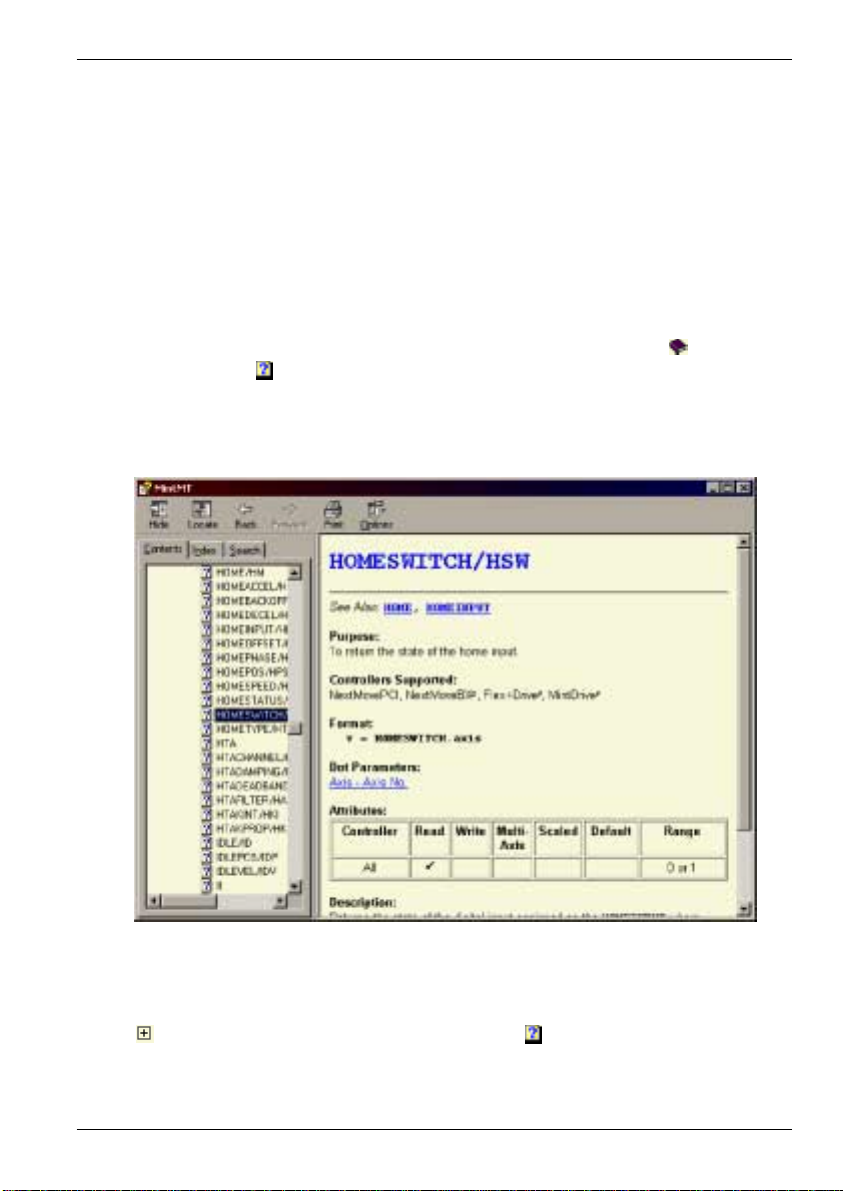
5.2.1 Help file
WorkBench v5 includes a comprehensive help file that contains information about every
MintMT keyword, how to use WorkBench and background information on motion control
topics. The help file can be displayed at any time by pressing F1. On the left of the help
window, the Contents tab shows the tree structure of the help file; each book
number of topics
allows you to search for them by name. The Search tab allows you to search for words or
phrases appearing anywhere in the help file. Many words and phrases are underlined and
highlighted with a color (normally blue) to show that they are links. Just click on the link to go
to an associated keyword. Most keyword topics begin with a list of relevant See Also links.
. The Index tab provides an alphabetic list of all topics in the file, and
contains a
Figure 10 - The WorkBench help file
For help on using WorkBench v5, click the Contents tab, then click the small plus sign
beside the Wor kBench v5 book icon. Double click a topic name to display it.
Operation 5-7MN1903
Page 50
5.3 Configuring an axis
The NextMove PCI is capable of controlling servo and stepper axes. This section describes
the basic setup for both types of axis. Commands typed in the Command window have
immediate effect - they do not need to be separately downloaded to the NextMove PCI.
5.3.1 Choosing an axis - 1, 2, 3 and 4 axis cards
For the 1, 2, 3 and 4 axis cards, each axis can be configured as either a servo axis or a
stepper axis. The factory preset configuration for all the axes is servo. If a stepper axis is
required it must be configured:
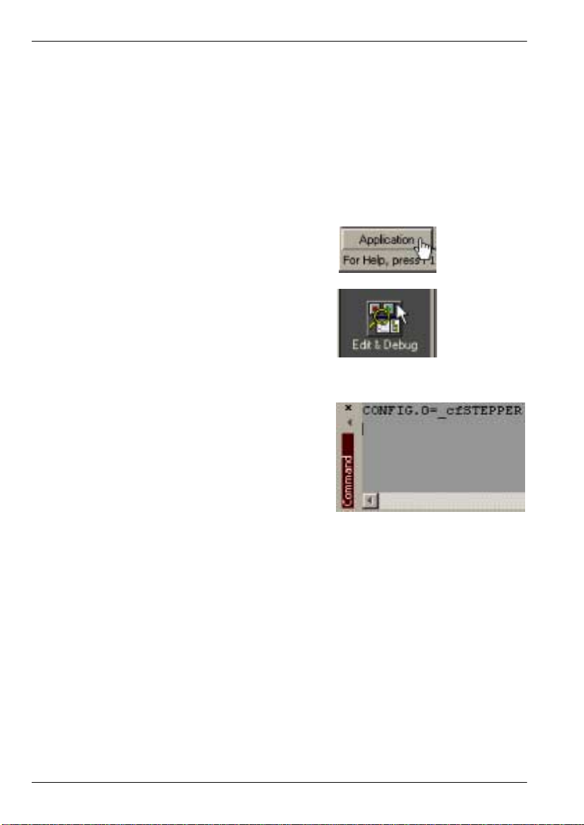
1. In the Toolbox, click Application, then
click the Edit & Debug icon.
2. Click in the Command window.
3. Type the command
CONFIG.0=_cfSTEPPER
where 0 is the axis to be configured.
Press Enter to enter the value. This
immediately sets axis 0 to be a stepper
axis.
Note: For NextMove PCI products, axis numbering always begin at 0. For example, a
four axis card has axes numbered 0, 1, 2 and 3.
When an axis is configured as a stepper axis, it uses the correspondingly numbered stepper
output channel. For example, axis 0 will use stepper channel 0 as its output (breakout module
connector X10, pins 1, 2, 6 and 7). See section 4.5.5 for details of the stepper channel
outputs.
5.3.2 Choosing an axis - 8 axis card
For the 8 axis card, the axis configuration is preset. Axes 0 to 3 are servo axes and axes 4 to
7 are stepper axes. No further axis configuration is necessary.
5-8 Operation MN1903
Page 51
5.3.3 Selecting a scale
MintMT defines all positional and speed related motion keywords in terms of encoder
quadrature counts (for servo motors) or steps for stepper motors. The number of quadrature
counts (or steps) is divided by the SCALE factor allowing you to use units more suitable for
your application. The unit defined by setting a value for scale is called the user unit (uu).
Consider a motor with a 1000 line encoder. This provides 4000 quadrature counts for each
revolution. If SCALE is not set, a MintMT command that involves distance, speed, or
acceleration may need to use a large number to specify a significant move. For example
MOVER=16000 (Move Relative) would rotate the motor by 16000 quadrature counts - only four
revolutions. By setting a SCALE factor of 4000, the user unit becomes revolutions. The more
understandable command MOVER=4 could now be used to move the motor four revolutions.
In applications involving linear motion a suitable value for SCALE would allow commands to
express values in linear distance, for example inches, feet or millimetres.
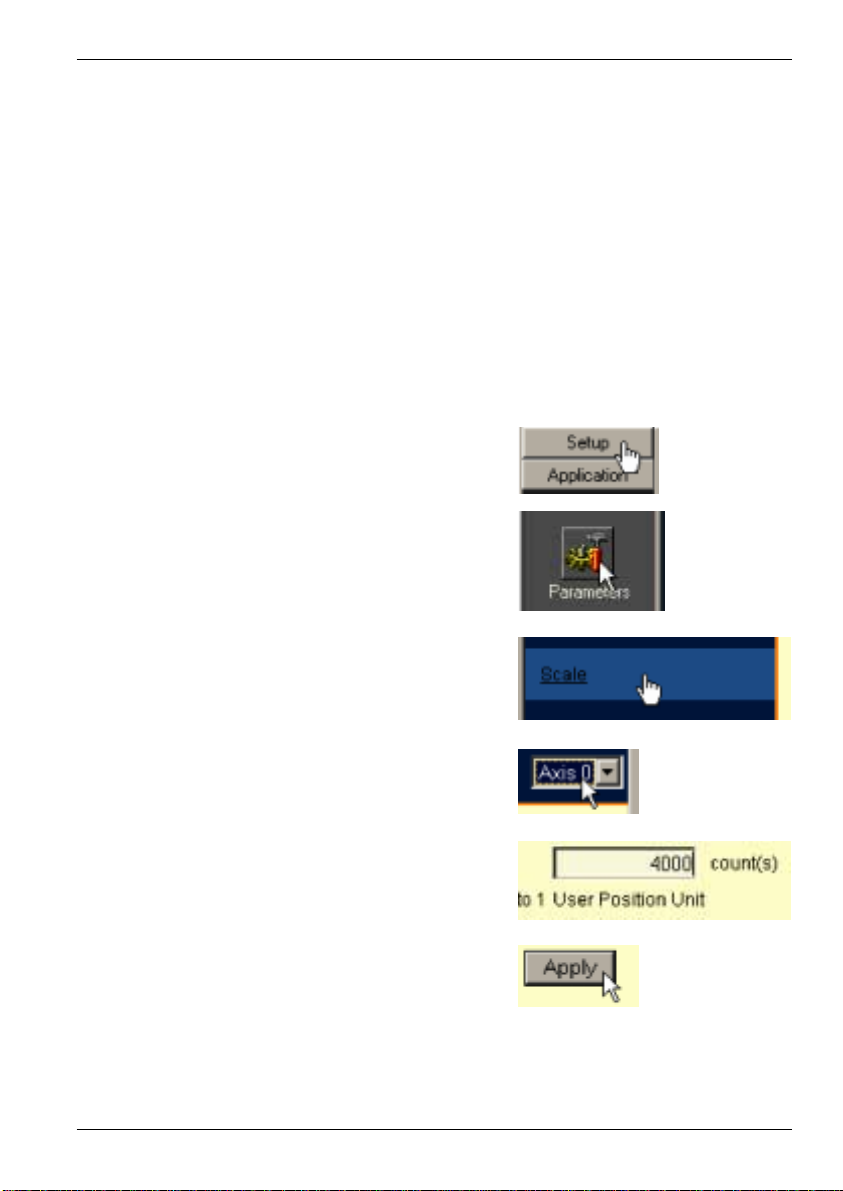
1. In the Toolbox, click Setup, then click
the Parameters icon.
2. Click the Scale tab.
3. Click in the Axis drop down box to select the
axis. Each axis can have a different scale if
required.
4. Click in the Scale box and type a value.
5. Click Apply.
This immediately sets the scaling factor for
the selected axis which will remain in the
NextMove PCI until another scale is defined
or power is removed from the NextMove PCI.
Operation 5-9MN1903
Page 52
5.3.4 Setting the drive enable output
The drive enable output allows NextMove PCI to disable the drive in the event of an error.
Each axis can be configured with its own drive enable output, or can share an output with
other axes. If an output is shared, an error on any of the axes sharing the output will cause all
of them to be disabled.
The drive enable output can either be a digital output or the relay.
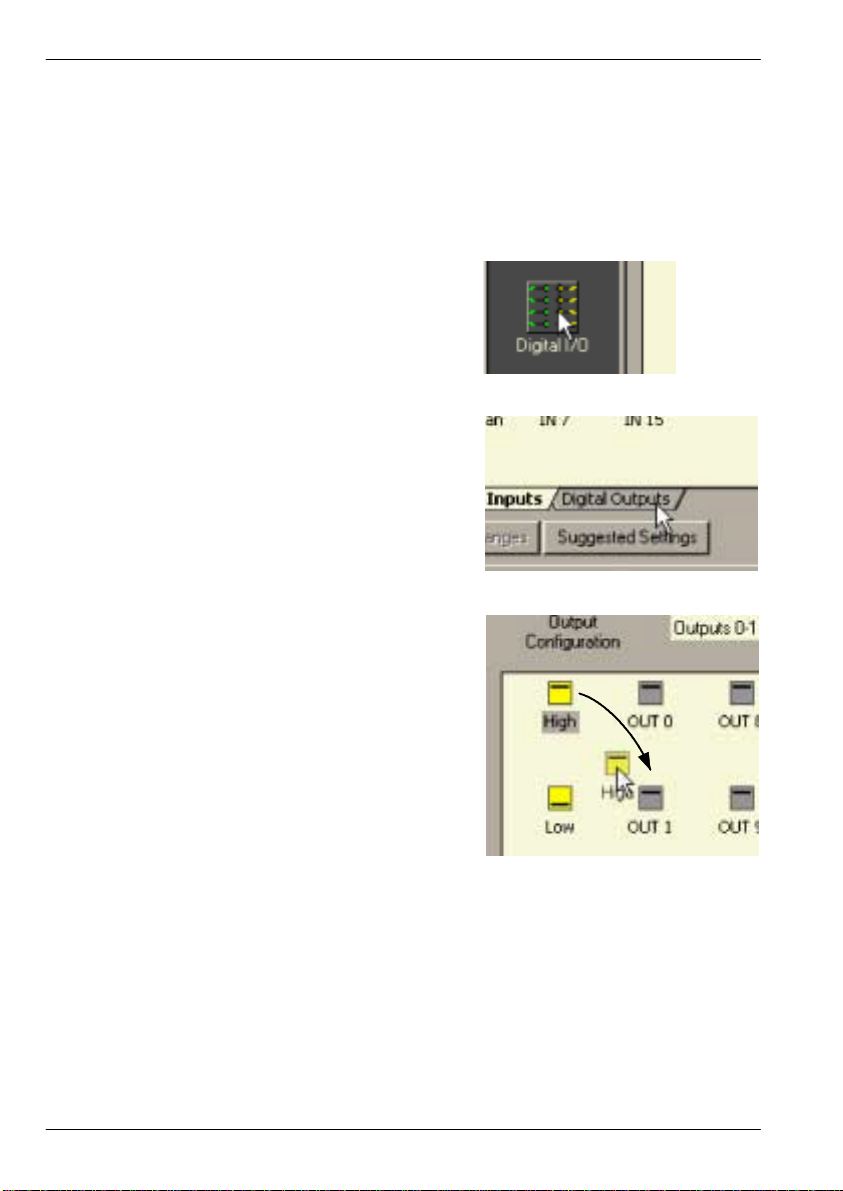
1. In the Toolbox, click the Digital I/O icon.
2. At the bottom of the Digital I/O screen, click
the Digital Outputs tab.
The left of the screen shows a column of
yellow icons - High, Low, Rising, Falling and
Rise/Fall. These describe how the output
should behave when activated (to enable the
axis).
3. If you are going to use the relay, ignore this
step and go straight to step 4.
If you are going to use a digital output, drag
the appropriate yellow icon to the grey OUT
icon that will be used as the drive enable
output. Its color will change to bright blue.
5-10 Operation MN1903
Page 53

4. If you are going to use the relay, drag the grey Relay0 icon to the grey X axis icon on the right
of the screen. To configure multiple axes to use the relay, repeat this step for the other axes.
If you are using a digital output, drag the bright blue OUT icon to the grey X axis icon on the
right of the screen. To configure multiple axes with the same drive enable output, repeat this
step for the other axes.
5. Click Apply at the bottom of the screen. This
sends the output configuration to the
NextMove PCI.
5.3.5 Testing the drive enable output
1. On the main WorkBench v5 toolbar, click the
Drive enable button. Click the button again.
Each time you click the button, the drive
enable output is toggled.
When the button is in the pressed (down)
position the drive should be enabled. When
the button is in the raised (up) position the
drive should be disabled.
If this is not working, or the action of the button is reversed, check the electrical
connections between the breakout module and the drive.
If you are using the relay output, check that you are using the correct normally open or
normally closed connection.
If you are using a digital output, check that it is using the correct high, low, edge or rise/fall
triggering method expected by the drive.
Operation 5-11MN1903
Page 54
5.4 Servo axis - testing and tuning
This section describes the method for testing and tuning a servo axis. To test a stepper axes,
go straight to section 5.8.
5.4.1 Testing the drive command output
This section tests the operation and direction of the axis command output. It is recommended
that the motor is disconnected for this test.
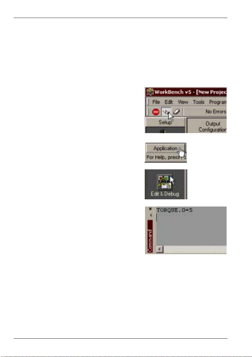
1. Check that the Drive enable button is
pressed (down).
2. In the Toolbox, click Application then click
the Edit & Debug icon.
3. Click in the Command window.
4. Type:
TORQUE.0=5
where 0 is the axis (demand output) to be
tested. In this example, this should cause a
demand of +5% of maximum output (0.5V)
to be produced at the Demand 0 output
(breakout module connector X7, pin 1).
See section 4.3.2 for details of the demand outputs. In WorkBench v5, look at the Spy
window located on the right of the screen. The virtual LED Command display should show
5 (approximately). If there seems to be no command output, check the electrical
connections between the breakout module and the drive.
5. To repeat the tests for negative (reverse) demands, type:
TORQUE.0=-5
This should cause a demand of -5% of maximum output (-0.5V) to be produced at the
Demand 0 output.
5-12 Operation MN1903
Page 55

6. To remove the demand and stop the test, type:
STOP.0
This should cause the demand produced at
the Demand 0 output to become 0V.
5.4.2 An introduction to closed loop control
This section describes the basic principles of closed loop control. If you are familiar with
closed loop control go straight to section 5.5.1.
When there is a requirement to move an axis, the NextMove PCI control software translates
this into a demand output voltage. This is used to control the drive (servo amplifier) which
powers the motor. An encoder or resolver on the motor is used to measure the motor’s
position. Every 1ms* (adjustable using the LOOPTIME keyword) the NextMove PCI compares
the demanded and measured positions. It then calculates the demand needed to minimize the
difference between them, known as the following error.
This system of constant measurement and correction is known as closed loop control.
[ For the analogy, imagine you are in your car waiting at an intersection. You are going to go
straight on when the lights change, just like the car standing next to you which is called
Demand. You’re not going to race Demand though - your job as the controller (NextMove PCI)
is to stay exactly level with Demand, looking out of the window to measure your position ].
The main term that the NextMove PCI uses to correct the error is called Proportional gain
(KPROP). A very simple proportional controller would simply multiply the amount of error by
the Proportional gain and apply the result to the motor [ the further Demand gets ahead or
behind you, the more you press or release the gas pedal ].
If the Proportional gain is set too high overshoot will occur, resulting in the motor vibrating back
and forth around the desired position before it settles [ you press the gas pedal so hard you go
right past Demand. To try and stay level you ease off the gas, but end up falling behind a little.
You keep repeating this and after a few tries you end up level with Demand, travelling at a
steady speed. This is what you wanted to do but it has taken you a long time ].
If the Proportional gain is increased still further, the system becomes unstable [ you keep
pressing and then letting off the gas pedal so hard you never travel at a steady speed ].
To reduce the onset of instability, a term called Velocity Feedback gain (KVEL) is used. This
resists rapid movement of the motor and allows the Proportional gain to be set higher before
vibration starts. Another term called Derivative gain (KDERIV) can also be used to give a
similar effect.
With Proportional gain and Velocity Feedback gain (or Derivative gain) it is possible for a
motortocometoastopwithasmallfollowingerror[Demandstopped so you stopped too, but
not quite level ].
The NextMove PCI tries to correct the error, but because the error is so small the amount of
torque demanded might not be enough to overcome friction.
* The 1ms sampling interval can be changed using the LOOPTIME keyword to either 500µs or
200µs.
Operation 5-13MN1903
Page 56

This problem is overcome by using a term called Integral gain (KINT). This sums the error
over time, so that the motor torque is gradually increased until the positional error is reduced to
zero [ like a person gradually pushing harder and harder on your car until they’ve pushed it
level with Demand].
However, if there is large load on the motor (it is supporting a heavy suspended weight for
example), it is possible for the output to increase to 100% demand. This effect can be limited
using the KINTLIMIT keyword which limits the effect of KINT to a given percentage of the
demand output. Another keyword called KINTMODE can even turn off integral action when it’s
not needed.
The remaining gain terms are Velocity Feed forward (KVELFF) and Acceleration Feed
forward (KACCEL) described below.
In summary, the following rules can be used as a guide:
H KPROP: Increasing KPROP will speed up the response and reduce the effect of
disturbances and load variations. The side effect of increasing KPROP is that it also
increases the overshoot, and if set too high it will cause the system to become unstable.
The aim is to set the Proportional gain as high as possible without getting overshoot,
instability or hunting on an encoder edge when stationary (the motor will buzz).
H KVEL: This gain has a damping effect, and can be increased to reduce any overshoot. If
KVEL becomes too large it will amplify any noise on the velocity measurement and
introduce oscillations.
H KINT: This gain has a de-stabilizing effect, but a small amount can be used to reduce any
steady state errors. By default, KINTMODE is set so that the KINT term is either ignored,
or is only applied during periods of constant velocity.
H KINTLIMIT: The integration limit determines the maximum value of the effect of integral
action. This is specified as a percentage of the full scale demand.
H KDERIV: This gain has a damping effect. The Derivative action has the same effect as
the velocity feedback if the velocity feedback and feedforward terms are equal.
H KVELFF: This is a feed forward term and as such has a different effect on the servo
system than the previous gains. KVELFF is outside the closed loop and therefore does
not have an effect on system stability. This gain allows a faster response to demand
speed changes with lower following errors, for example you would increase KVELFF to
reduce the following error during the slew section of a trapezoidal move. The trapezoidal
test move can be used to fine-tune this gain. This term is especially useful with velocity
controlled servos
H KACCEL: This term is designed to reduce velocity overshoots on high acceleration
moves. Due to the quantization of the positional data and the speed of the servo loop, for
the acceleration feed forward term to affect the servo loop the acceleration of the axis
must exceed 1,000,000 encoder counts per second.
5-14 Operation MN1903
Page 57
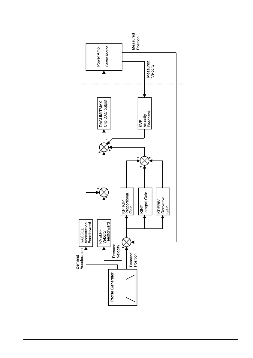
Figure 11 - The NextMove PCI servo loop
Operation 5-15MN1903
Page 58

5.5 Servo axis - tuning for current control
5.5.1 Selecting servo loop gains
All servo loop parameters default to zero, meaning that the demand output will be zero at
power up. Most servo amplifiers can be set to current (torque) control mode or velocity control
mode; check that the servo amplifier will operate in the correct mode. The procedure for
setting system gains differs slightly for each. To tune an axis for velocity control, go straight to
section 5.7. It is recommended that the system is initially tested and tuned with the motor shaft
disconnected from other machinery.
Note: The method explained in this section should allow you to gain good control of the
motor, but will not necessarily provide the optimum response without further
fine-tuning. Unavoidably, this requires a good understanding of the effect of the
gain terms.
1. In the Toolbox, click the Fine-tuning icon.
The Fine-tuning window is displayed at the
right of the screen. The main area of the
WorkBench v5 window displays the Capture
window. When tuning tests are performed,
this will display a graph representing the
response.
2. In the Fine-tuning window, click in the
KDERIV box and enter a starting value of 1.
Click Apply and then turn the motor shaft by
hand. Repeat this process, slowly increasing
the value of KDERIV until you begin to feel
some resistance in the motor shaft. The
exact value of KDERIV is not critical at this
stage.
5-16 Operation MN1903
Page 59

3. Click in the KPROP box and enter a value
that is approximately one quarter of the value
of KDERIV. If the motor begins to vibrate,
decrease the value of KPROP or increase
the value of KDERIV until the vibration stops.
Small changes may be all that is necessary.
4. In the Move Type drop down box, check that
the move type is set to Step.
5. Click in the Distance box and enter a distance
for the step move. It is recommended to set
a value that will cause the motor to turn a
short distance, for example one revolution.
Note: The distance depends on the scale set in section 5.3.3.
If you set a scale so that units could be expressed in revolutions (or other unit of
your choice), then those are the units that will be used here. If you did not set a
scale, the amount you enter will be in encoder counts.
6. Click in the Duration box and enter a duration
for the move, in seconds. This should be a
short duration, for example 0.15 seconds.
7. Click Go.
The NextMove PCI will perform the move and the motor will turn. As the soon as the
move is completed, WorkBench v5 will download captured data from the NextMove PCI.
The data will then be displayed in the Capture window as a graph.
Note: The graphs that you see will not look exactly the same as the graphs shown here!
Remember that each motor has a slightly different response.
8. Using the check boxes below the graph,
select the traces you require, for example
Demand position and Measured position.
Operation 5-17MN1903
Page 60

5.5.2 Underdamped response
If the graph shows that the response is underdamped (it overshoots the demand, as shown in
Figure 12) then the value for KDERIV should be increased to add extra damping to the move.
If the overshoot is excessive or oscillation has occurred, it may be necessary to reduce the
value of KPR OP.
Measured position
Demand position
Figure 12 - Underdamped response
9. Click in the KDERIV and/or KPROP boxes
and make the required changes. The ideal
response is shown in section 5.5.4.
5-18 Operation MN1903
Page 61

5.5.3 Overdamped response
If the graph shows that the response is overdamped (it reaches the demand too slowly, as
shown in Figure 13) then the value for KDERIV should be decreased to reduce the damping of
the move. If the overdamping is excessive, it may be necessary to increase the value of
KPROP.
Demand
position
10. Click in the KDERIV and/or KPROP boxes
and make the required changes. The ideal
response is shown in section 5.5.4.
Measured position
Figure 13 - Overdamped response
Operation 5-19MN1903
Page 62

5.5.4 Critically damped response
If the graph shows that the response reaches the demand quickly and only overshoots the
demand by a small amount, this can be considered an ideal response for most systems.
See Figure 14.
Demand position
Measured position
Figure 14 - Critically damped (ideal) response
5-20 Operation MN1903
Page 63
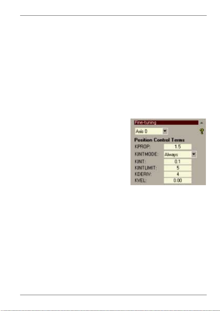
5.6 Servo axis - eliminating steady-state errors
In systems where precise positioning accuracy is required, it is often necessary to position
within one encoder count. Proportional gain, KPROP, is not normally able to achieve this
because a very small following error will only produce a small demand for the drive which may
not be enough to overcome mechanical friction (this is particularly true in current controlled
systems). This error can be overcome by applying integral gain. The integral gain, KINT,
works by accumulating following error over time to produce a demand sufficient to move the
motor into the required position with zero following error.
KINT can therefore overcome errors caused by gravitational effects such as vertically moving
linear tables. With current controlled drives a non-zero demand output is required to hold the
load in the correct position, to achieve zero following error.
Care is required when setting KINT since a high value will cause instability during moves. A
typical value for KINT would be 0.1. The effect of KINT should also be limited by setting the
integration limit, KINTLIMIT , to the smallest possible value that is sufficient to overcome friction
or static loads, for example 5. This will limit the contribution of the integral term to 5% of the full
DAC output range.
1. Click in the KINT box and enter a small
starting value, for example 0.1.
2. Click in the KINTLIMIT box and enter a value
of 5.
With NextMove PCI, the action of KINT and KINTLIMIT can be set to operate in various
modes:
H Never - the KINT term is never applied
H Always - the KINT term is always applied
H Smart - the KINT term is only applied when the demand is zero or constant.
This function can be selected using the KINTMODE drop down box.
Operation 5-21MN1903
Page 64

5.7 Servo axis - tuning for velocity control
Drives designed for velocity control incorporate their own velocity feedback term to provide
system damping. For this reason, KDERIV (and KVEL) can be set to zero.
Correct setting of the velocity feed forward gain KVELFF is important to get the optimum
response from the system. The velocity feed forward term takes the instantaneous velocity
demand from the profile generator and adds this to the output block (see Figure 11).
KVELFF is outside the closed loop and therefore does not have an effect on system stability.
This means that the term can be increased to maximum without causing the motor to oscillate,
provided that other terms are setup correctly.
When setup correctly, KVELFF will cause the motor to move at the speed demanded by the
profile generator. This is true without the other terms in the closed loop doing anything except
compensating for small errors in the position of the motor. This gives faster response to
changes in demand speed, with reduced following error.
5.7.1 Calculating KVELFF
To calculate the correct value for KVELFF, you will need to know:
H The speed, in revolutions per minute, produced by the motor when a maximum demand
(+10V) is applied to the drive.
H The setting for LOOPTIME. The factory preset setting is 1ms.
H The number of encoder lines for the attached motor. Baldor BSM motors use either 1000
or 2500 line encoders.
The servo loop formula uses speed values expressed in quadrature counts per servo loop.To
calculate this figure:
1. First, divide the speed of the motor, in revolutions per minute, by 60 to give the number of
revolutions per second. For example, if the motor speed is 3000rpm when a maximum
demand (+10V) is applied to the drive:
Revolutions per second = 3000 / 60
2. Next, calculate how many revolutions will occur during one servo loop. The factory preset
servo loop time is 1ms (0.001 seconds), so:
Revolutions per servo loop = 50 x 0.001 seconds
3. Now calculate how many quadrature encoder counts there are per revolution. The NextMove
PCI counts both edges of both pulse trains (CHA and CHB) coming from the encoder, so for
every encoder line there are 4 ‘quadrature counts’. With a 1000 line encoder:
Quadrature counts per revolution = 1000 x 4
4. Finally, calculate how many quadrature counts there are per servo loop:
Quadrature counts per servo loop = 4000 x 0.05
=
50
=
0.05
=
4000
=
200
5-22 Operation MN1903
Page 65
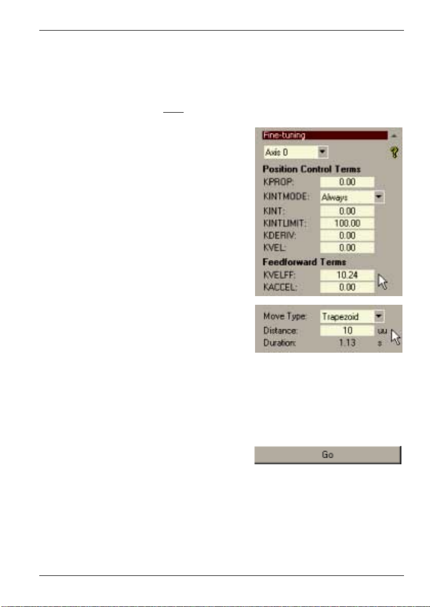
The analog demand output is controlled by a 12-bit DAC, which can create output voltages in
the range -10V to +10V. This means a maximum output of +10V corresponds to a DAC value
of 2048. The value of KVELFF is calculated by dividing 2048 by the number of quadrature
counts per servo loop, so:
KVELFF = 2048 / 200
5. Click in the KVELFF box and enter the value.
The calculated value should give zero
following error in normal operation. Using
values greater than the calculated value will
cause the controller to have a following
error ahead of the desired position. Using
values less than the calculated value will
cause the controller to have following error
behind the desired position.
6. In the Move Type drop down box, check that
the move type is set to Trapezoid.
7. Click in the Distance box and enter a distance
for the step move. It is recommended to set
a value that will cause the motor to make a
few revolutions, for example 10.
=
10.24
Note: The distance depends on the scale set in section 5.3.3. If you set a scale so that
units could be expressed in revolutions (or other unit of your choice), then those
are the units that will be used here. If you did not set a scale, the amount you
enter will be in encoder counts.
8. Click Go.
The NextMove PCI will perform the move and the motor will turn. As the soon as the
move is completed, WorkBench v5 will download captured data from the NextMove PCI.
The data will then be displayed in the Capture window as a graph.
Note: The graph that you see will not look exactly the same as the graph shown here!
Remember that each motor has a slightly different response.
Operation 5-23MN1903
Page 66

9. Using the check boxes below the graph,
select the Measured velocity and Demand
velocity traces.
Demand velocity
Measured velocity
Figure 15 - Correct value of KVELFF
It may be necessary to make changes to the calculated value of KVELFF. If the trace for
Measured velocity appears above the trace for Demand velocity, reduce the value of KVELFF.
If the trace for Measured velocity appears below the trace for Demand velocity, increase the
value of KVELFF. Repeat the test after each change. When the two traces appear on top of
each other (approximately), the correct value for KVELFF has been found as shown in
Figure 11.
5-24 Operation MN1903
Page 67

5.7.2 Adjusting KPROP
The KPROP term can be used to reduce following error. Its value will usually be much smaller
than the value used for an equivalent current controlled system. A fractional value, for example
0.1, will probably give the best response.
1. Click in the KPROP box and enter a starting
value of 0.1.
2. Click Go.
The NextMove PCI will perform the move and the motor will turn. As the soon as the
move is completed, WorkBench v5 will download captured data from the NextMove PCI.
The data will then be displayed in the Capture window as a graph.
Note: The graph that you see will not look exactly the same as the graph shown here!
Remember that each motor has a slightly different response.
3. Using the check boxes below the graph,
select the Measured position and Demand
position traces.
Operation 5-25MN1903
Page 68
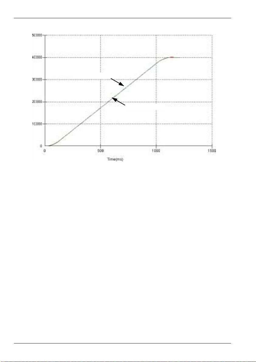
Demand position
Measured position
Figure 16 - Correct value of KPROP
The two traces will probably appear with a small offset from each other. Adjust KPROP by
small amounts until the two traces appear on top of each other (approximately), as shown in
Figure 16.
5-26 Operation MN1903
Page 69
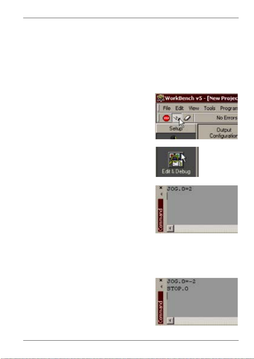
5.8 Stepper axis - testing
This section describes the method for testing a stepper axis. The stepper control is an open
loop system so no tuning is necessary.
5.8.1 Testing the drive command output
This section tests the operation and direction of the axis command output. It is recommended
that the system is initially tested and tuned with the motor shaft disconnected from other
machinery.
1. Check that the Drive enable button is
pressed.
2. In the Toolbox, click the Edit & Debug icon.
3. Click in the Command window.
4. Type:
JOG.0=2
where 0 is the axis (stepper output) to be
tested and 2 is the speed.
Note: The JOG command specifies a speed in user units per second, so the speed is
affected by SCALE (section 5.3.3).
If there appears to be no pulse or direction output, check the electrical connections
between the breakout module and the drive.
5. To repeat the tests for reverse moves, type:
JOG.0 = -2
6. To remove the demand and stop the test, type:
STOP.0
Operation 5-27MN1903
Page 70

5.9 Digital input/output configuration
The Digital I/O window can be used to setup other digital inputs and outputs.
5.9.1 Digital input configuration
The Digital Inputs tab allows you to define how each digital input will be triggered and,
optionally, if it is to be allocated to a special function, for example the Forward Limit. In the
following example, digital input 1 will be set to trigger on a falling edge, and allocated to the
forward limit input of axis 0:
1. In the Toolbox, click the Digital I/O icon.
2. At the bottom of the Digital I/O screen, click
the Digital Inputs tab.
The left of the screen shows a column of
yellow icons - High, Low, Rising, Falling
and Rise/Fall. These describe how the
input will be triggered.
3. Drag the Falling icon
onto the IN1 icon . This will setup IN1 to respond to a falling edge.
5-28 Operation MN1903
Page 71
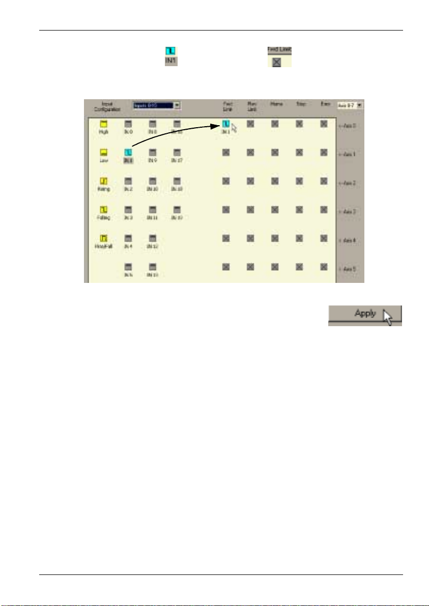
4. Now drag the IN1 icon onto the Fwd Limit icon .
This will setup IN1 as the Forward Limit input of axis 0.
5. Click Apply to send the changes to the NextMove PCI.
Note: If required, multiple inputs can be configured before clicking Apply.
5.9.2 Digital output configuration
The Digital Outputs tab allows you to define how each digital output will operate and if it is to
be allocated to a drive enable output (see section 5.3.4). Remember to click Apply to send the
changes to the NextMove PCI.
Operation 5-29MN1903
Page 72
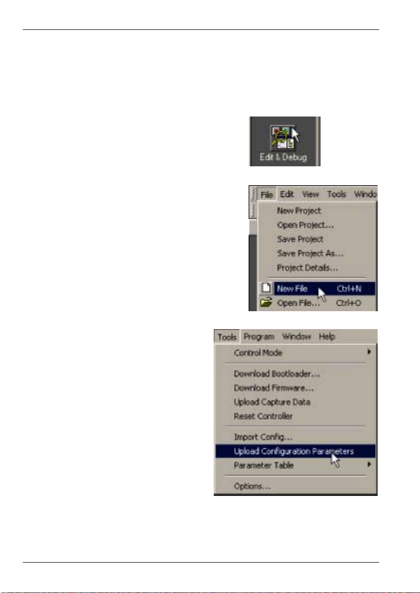
5.10 Saving setup information
When power is removed from the NextMove PCI all data, including configuration and tuning
parameters, is lost. Y ou should therefore save this information in a file, which can be loaded
when the card is next used. Alternatively, the information can be included in program files as
part of the Startup block.
1. In the Toolbox, click the Edit & Debug icon.
2. On the main menu, choose File, New File.
A new program editing window will appear.
3. On the main menu, choose Tools,
Upload Configuration Parameters.
WorkBench v5 will read all the
configuration information from the
NextMove PCI and place it in a Startup
block. For details of the Startup block,
see the MintMT help file.
5-30 Operation MN1903
Page 73
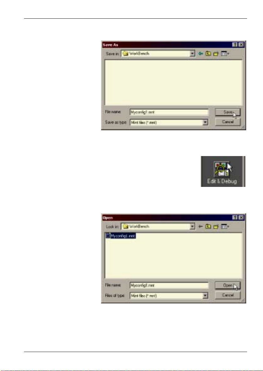
4. On the main menu, choose File, Save File. Locate a folder, enter a filename and click Save.
5.10.1Loading saved information
1. In the Toolbox, click the Edit & Debug icon.
2. On the main menu, choose File, Open File...
Locate the file and click Open.
A Startup block should be included in every Mint program, so that whenever a program is
loaded and run the NextMove PCI will be correctly configured. Remember that every
drive/motor combination has a slightly different response. If the same program is used on
a different NextMove PCI installation, the Startup block will need to be changed.
Operation 5-31MN1903
Page 74

5-32 Operation MN1903
Page 75

6 Troubleshooting
6.1 Introduction
This section explains common problems and their solutions.
If you want to know the meaning of the LED indicators, see section 6.2.
6.1.1 Problem diagnosis
If you have followed all the instructions in this manual in sequence, you should have few
problems installing the NextMove PCI. If you do have a problem, read this section first. In
WorkBench v5, use the Error Log tool to view recent errors and then check the help file. If you
cannot solve the problem or the problem persists, the SupportMet feature can be used.
6.1.2 SupportMet feature
The SupportMet feature (on the Help menu) can be used to e-mail information to the Baldor
representative from whom you purchased the equipment. If required, you can choose to add
your program files as attachments. WorkBench v5 will automatically start up your e-mail
program and begin a new message, with comprehensive system information and selected
attachments already in place. You can add any additional message of your own and then send
the e-mail. The PC must have email facilities to use the SupportMet feature. If you prefer to
contact Baldor technical support by telephone or fax, contact details are provided at the front
of this manual. Please have the following information ready:
6
H The serial number of your NextMove PCI (if known).
H Use the Help, SupportMe menu item in WorkBench v5 to view details about your system.
H The type of servo amplifier and motor that you are using.
H Give a clear description of what you are trying to do, for example performing fine-tuning.
H Give a clear description of the symptoms that you can observe, for example error
messages displayed in WorkBench v5, or the current value of any of the Mint error
keywords AXISERROR, AXISSTATUS, INITERROR, and MISCERROR.
H The type of motion generated in the motor shaft.
H Give a list of any parameters that you have setup, for example the gain settings you have
entered.
Troubleshooting 6-1MN1903
Page 76

6.2 NextMove PCI indicators
6.2.1 Status and CAN LEDs
The backplate of the NextMove PCI contains four LEDs. S1 and S2
represent general status information. C1 and C2 are CAN traffic
indicators. The LEDs may illuminate red or green and can be
continuous or flashing.
C1 C2
S1
S2
LED State(s)
All off NextMove PCI is not powered.
All red In hardware reset (see section 4.8).
All green,
cycling
All red,
cycling
S1 green,
flashing
S1 red,
flashing
S1 red,
flashing fast
S1 green,
flashing fast
All green,
flashing
Allred,turnoff
in sequence:
C1,S1,S2,C2
C2 green,
flashing
Meaning
In software reset, with no errors (see section 4.8).
In software reset, Power On Self Test (POST) error has occurred.
Program is running OK.
Program is running, but there is an initialization error.
Asynchronous error - for example, a limit switch has been activated.
Miscellaneous error - for example, the output driver board is not
working.
Updating firmware.
POST is in operation (after reset).
Message received on CAN2 bus.
6-2 Troubleshooting MN1903
Page 77

6.2.2 Communication
If the problem is not listed below please contact Baldor Technical Support. An oscilloscope will
be useful for many of the electrical tests described below.
Symptom
Cannot detect NextMove
PCI
Cannot communicate with
the controller.
6.2.3 Motor control
Symptom Check
Controller appears to be
working but will not cause
motor to turn.
Motor runs uncontrollably
when controller is switched
on.
Check
Check that the NextMove PCI driver has been installed.
Verify that WorkBench v5 is loaded and that NextMove PCI
is the currently selected controller. The MintMT operating
system (firmware) must be downloaded to the controller
each time it is powered.
Check the card is firmly seated in its socket in the computer
and this socket is of the correct type.
Check that the green S1 LED on the card backplate is
flashing (approximately twice per second).
Check that the connections between motor and drive are
correct. Use WorkBench v5 to perform the basic system
tests (see section 5.4 or 5.8).
Ensure that while the controller is not in error the drive is
enabled and working. When the controller is first powered up
the drive should be disabled if there is no program running
(there is often an LED on the front of the drive to indicate
status).
Check that the servo loop gains are setup correctly - check
the Fine-tuning window. See sections 5.4.2 to 5.6.
Check that the encoders are connected, they have power
through Encoder V+ (if required, see section 4.5.3) and are
functioning correctly. Use a dual trace oscilloscope to
display both channels of the encoder and/or the complement
signals simultaneously.
Check that the drive is connected correctly to the breakout
module and that with zero demand there is 0V at the drive
demand input. See section 5.4.1.
Verify that the breakout module and drive are correctly
grounded to a common earth point.
Troubleshooting 6-3MN1903
Page 78

Symptom Check
Motor runs uncontrollably
when controller is switched
on and servo loop gains are
applied or when a move is
set in progress. Motor then
stops after a short time.
Motor is under control, but
vibrates or overshoots
during a move.
Motor is under control, but
when moved to a position
and then back to the start it
does not return to the same
position.
Check that the axis’ corresponding encoder and demand
signals are connected to the same axes of motion. Check
the demand to the drive is connected with the correct
polarity.
Check that for a positive demand signal, a positive increase
in axis position is seen. The MintMT ENCODERMODE
keyword can be used to change encoder input direction.
The MintMT DACMODE keyword can be used to reverse DAC
output polarity.
Check that the maximum following error is set to a
reasonable value. For setting up purposes, following error
detection may be disabled by setting FOLERRORMODE = 0.
Servo loop gains may be set incorrectly. See sections 5.4.2
to 5.6.
Using an oscilloscope at the breakout module connectors,
check:
H all encoder channels are clear signals and free from
H they are correctly wired to the controller;
H when the motor turns, the two square wave signals are
Ensure that the encoder lead uses shielded twisted pair
cable and that the shield is attached to the shield connection
only at the breakout module end.
electrical noise;
90 degrees out of phase. Also check the complement
signals.
Verify that the breakout module and drive are correctly
grounded to a common earth point.
6-4 Troubleshooting MN1903
Page 79

7.1 Introduction
This section provides technical specifications of the NextMove PCI
7.1.1 Mechanical specifications
Description Value
Input power
(from host PC)
Input power
(from customer supply)
Power consumption 15W (PCI card only)
Weight Approximately 0.67lb (305g)
Nominal overall
dimensions
Operating temperature 0 - 40°C (32 - 104°F) ambient
+5V at 1200mA
±12V at 250mA
Additional current will be required when powering the
encoders from the host PC’s +5V supply.
+12V to +24V at 1200mA
Standard 7in PCI card
175mm (6.875in) long x 106.7mm (4.2in) high.
7 Specifications
7
The host PC must have a spare 7 inch PCI card slot. Additional slots will be required to
accommodate expansion cards. The PC must be an AT type - the card cannot be fitted into
MCA type machines. The card dimensions conform to the PCI standard except that it cannot
be fitted with a Micro Channel bracket.
7.1.2 Analog inputs (X6)
Description Unit Value
Type Single ended or differential
Common mode voltage range VDC ±10
Input impedance kΩ >5
Input ADC resolution bits 12
Equivalent resolution (±10V input) mV ±4.9
Sampling interval µs 400
(software selectable)
(includes sign bit)
Specifications 7-1MN1903
Page 80

7.1.3 Analog outputs (Drive Demand/Command - X7)
Description Unit Value
Type Bipolar
Output voltage range VDC ±10
Output current (max) mA 1
Output DAC resolution bits 14
Equivalent resolution mV ±1.22
Update interval Immediate
7.1.4 Digital inputs (X1 & X2)
Description Unit Value
Type VDC Opto-isolated, AC inputs
Input voltage (Active high)
Nominal
Minimum
Input voltage (Active low)
Nominal
Maximum
Input current (approximate, per input) mA 8
Sampling interval ms 1
VDC
VDC
(includes sign bit)
24
12
0
2
7.1.5 Digital inputs (X3)
Description Unit Value
Type VDC Non-isolated, AC inputs
Input voltage (Active high)
Nominal
Minimum
Input voltage (Active low)
Nominal
Maximum
Input current (approximate, per input) mA 8
Sampling interval ms 1
7-2 Specifications MN1903
VDC
24
12
VDC
0
2
Page 81

7.1.6 Digital outputs (X4)
Description Unit Value
Output current
(maximum, each output)
Update interval Immediate
7.1.7 Relay output (X8)
Description Unit Value
Contacts Normally closed
Contact rating (resistive) 1A @ 24VDC
Maximum carrying current A 2
Maximum switching power 62.5VA, 30W
Maximum switching voltage 125VAC, 60VDC
Maximum switching current A 1
Contact resistance (maximum) mΩ 100
Update interval Immediate
7.1.8 Encoder interfaces (X12 - X16)
mA
50
or
0.5A @ 125VAC
Description Unit Valu e
Encoder input A/B Differential, Z index
Maximum input frequency
(quadrature)
Output power supply to encoders
Total, if sourced from host PC
Total, if sourced from user supply
Maximum recommended cable
length
MHz 1.87
5V, 500mA max.
30V, 3A max.
30.5m (100ft)
Specifications 7-3MN1903
Page 82

7.1.9 Stepper outputs (X10 & X11)
Description Unit Valu e
Output type Pulse (step) and direction
Maximum output frequency MHz 3
Output voltage 5V
Output current mA 20 max.
7.1.10CANopen interface (X17)
Description Unit Valu e
Signal 2-wire, isolated
Channels 1
Bit rate Kbit/s 10, 20, 50, 100, 125, 250, 500, 800, 1000
Protocol CANopen
7.1.11Baldor CAN interface (X18)
Description Unit Valu e
Signal 2-wire
Channels 2
Bit rate Kbit/s 10, 20, 50, 125, 250, 500, 800, 1000
Protocol Baldor CAN
7-4 Specifications MN1903
Page 83
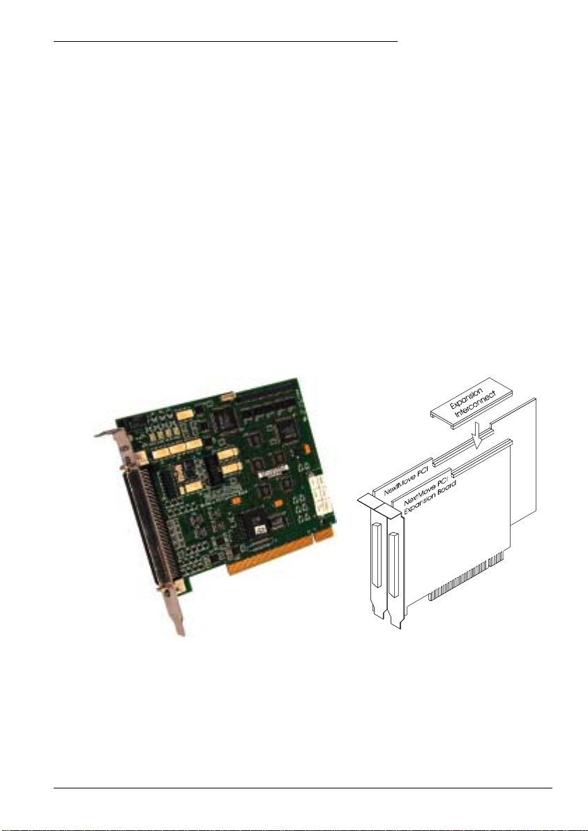
A Accessories
A.1 Introduction
NextMove PCI is supplied with a software license to control 1, 2 ,3, 4 or 8 axes. Similarly, the
NextMove PCI Expansion Card is supplied with a software license to control a further 4 or 8
axes. A license cannot be upgraded.
A.1.1 NextMove PCI Expansion card
The NextMove PCI Expansion Card is available in 4 or 8 axis variants and provides an
additional 20 digital inputs, 12 digital outputs, 4 analog inputs, 4 analog outputs (drive
command outputs) and a relay. However, there are no CAN functions. The electrical
specification of the I/O is the same as the main NextMove PCI card. The card requires its own
additional breakout module and 100-pin cable.
NextMove PCI supports either one or two expansion cards. Connection to the cards is made
through a bridging PCB (the expansion interconnect) that connects across the top of the
cards.
A
Figure 17 - NextMove PCI Expansion card
Note: If two expansion cards are used then the dual interconnect board is needed. It is
advisable to exert a retaining force on the interconnect board, to prevent it working
loose due to vibration.
Accessories A-1MN1903
Page 84

A description of the catalog numbers are shown in the following table:
Mai
Catalog
number
PCI002-501 NextMove PCI Expansion card with PNP digital outputs, 4 axis
PCI002-502 NextMove PCI Expansion card with PNP digital outputs, 8 axis
PCI002-503 NextMove PCI Expansion card with NPN digital outputs, 4 axis
PCI002-504 NextMove PCI Expansion card with NPN digital outputs, 8 axis
OPT025-504
OPT025-505
The relay on the expansion card can be accessed by using the MintMT RELAY keyword, with
the bank dot parameter set to 1. For example, RELAY.1=1 will activate the relay on the first
expansion card. The RELAY keyword cannot be used if the relay is being used as a drive
enable output. See the MintMT help file.
Connections to the expansion card’s relay are present only on the breakout module attached
to the expansion card.
Description
Expansion interconnect card to connect NextMove PCI to one expansion
card
Dual expansion interconnect card to connect NextMove PCI to two
expansion cards
A.1.2 Axis numbering when using expansion card(s)
The main NextMove PCI card is available in 1, 2, 3, 4, or 8 axis variants. The expansion card
isavailablein4or8axisvariants.However,usinga8axismaincardanda8axisexpansion
card will not provide 16 axes of control. This is because the NextMove PCI system can control
a maximum 12 axes. Also, when the 1, 2 or 3 axis NextMove PCI cards are used, some axis
numbers become unavailable.
The axis numbers available for different combinations of hardware are summarized in the
following table:
n
NextMove
PCI
card model
1 axis 0 04-7 04-11 04-78-11
2 axes 0,1 0,1 4-7 0,1 4-11 0,1 4-7 8-11
3 axes 0,1,2 0,1,2 4-7 0,1,2 4-11 0,1,2 4-7 8-11
4 axes 0-3 0-3 4-7 0-3 4-11 0-3 4-7 8-11
8 axes 0-7 0-7 8-11 0-7 8-11
With no
expansion
main main expansion main expansion main exp1 exp2
Table 5 - Available axis numbers and locations
One 4-axis
expansion card
Expansion cards
One 8-axis
expansion card
expansion cards
A-2 Accessories MN1903
Two 4-axis
Page 85

A.1.3 Expansion card status LEDs
The backplate of the NextMove PCI Expansion card contains two LEDs, S1 and S2. These
represent general status information. The LEDs may illuminate red or green and can be
continuous or flashing.
Expansion card LED
State(s)
Both off The expansion card is not powered.
Both red In hardware reset (see section 4.8).
Both green,
flashing alternately
Both red,
flashing alternately
S1 green,
flashing
S1 red,
flashing
S2 red,
flashing fast
S2 green,
flashing fast
Meaning
In software reset, with no errors (see section 4.8).
In software reset, Power On Self Test (POST) error has occurred.
Program is running OK.
Program is running, but there is an initialization error.
Asynchronous error - for example, a limit switch has been activated.
Miscellaneous error - for example, the output driver board is not
working.
Accessories A-3MN1903
Page 86
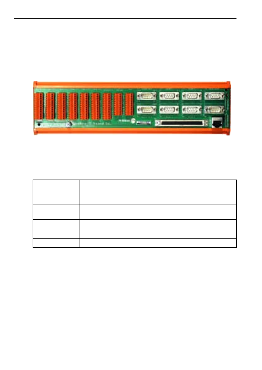
A.1.4 NextMove PCI Breakout module
Breakout modules are available for use with the NextMove PCI and expansion cards,
providing one or two part screw-down terminals for the I/O, power and relay connections, with
9-pin D-type connectors for the encoders and steppers. CAN connections are brought out on a
CANopen compatible D-type for CAN1 (CANopen) and an RJ45 for CAN2 (Baldor CAN). For
further details of each connector, see section 4. The breakout module connects to the
NextMove PCI or expansion card using a 100-pin cable.
Figure 18 - NextMove PCI Breakout module
The breakout module is approximately 292mm (11.50in) long by 70mm (2.76in) wide by 62mm
(2.45in) high. It is designed to mount on either a 35mm symmetric DIN rail (EN 50 022, DIN
46277-3) or a G-profile rail (EN 50 035, DIN46277-1). Ready-made cables of different lengths
are available for connecting between the breakout module and NextMove PCI:
Catalog number
PCI003-501
PCI002-502
CBL021-501 1.0m 100-pin cable to attach card to breakout module
CBL021-503 1.5m 100-pin cable to attach card to breakout module
CBL021-503 3.0m 100-pin cable to attach card to breakout module
The shield connections on the breakout module are all connected internally. These include:
H the ‘shield’ pins present on many connectors
H the metal backshell of all of the D-type connectors, the CAN connectors and the 100-pin
connector
H the stud located below connectors X3 and X4.
If the breakout module (Issue 2) is being used to replace an existing Issue 1 breakout module,
the power connections must be altered. Connections that were previously made to pins 3, 4, 5
and 6 of the J10 power connector on the Issue 1 board must now be connected only to pins 5
and 6 of the Issue 2 module’s power connector X9. The issue number of the board is printed
below the main title, near connectors X5 and X6.
When connected to an expansion card, the breakout module’s two CAN connectors are
inactive.
Description
Breakout module: Single part screw down terminals and signal
conditioning.
Breakout module: Two part screw down terminals and signal
conditioning.
A-4 Accessories MN1903
Page 87

A.1.5 Digital output modules
The digital output drive on NextMove PCI is in the form of a removable module which allows
different types of outputs for different applications. Currently there are two modules available:
Catalog
number
OPT025-508 NPN - N-channel unprotected MOSFET module for current sinking outputs
OPT025-507
Description
PNP - Darlington module for current sourcing outputs, with built in fly-back
diodes.
A.1.6 NextMove PC system adapter
The NextMove PC adapter takes the output from the 100-pin connector of NextMove PCI and
converts it to be compatible with the NextMove PC cable, allowing for machine conversion
from NextMove PC to NextMove PCI with minimal change to the physical wiring of the
machine.
Catalog
number
OPT026-506 Allows NextMove PCI to connect to a NextMove PC system.
Note: If the NextMove PC Breakout module is also being used, the digital input banks
Description
use one common connection. The USR V+ supply is used to determine the sense
of the digital inputs. Connecting CGND to the common connection will cause
inputs to be active high (active when a +24V is applied). Connecting USR V+ to
the common connection will cause inputs to be active low (active when a 0V is
applied). Jumpers on the system adapter select whether USR V+ or CGND is
connected to the common connection.
A.1.7 Spares
Catalog
number
FU056A01 NextMove PCI - Strip of 10 fuses for the digital outputs.
OPT025-501* Cable to allow NextMove PCI to connect to a NextMove PC system.
OPT025-502*
OPT025-503*
Description
Non-isolated CAN transceiver (SIL hybrid module).
Supports speeds up to 500Kbit/s.
Isolated CAN transceiver (SIL hybrid module).
Supports speeds up to 1Mbit/s.
*These items are located on the breakout module.
Accessories A-5MN1903
Page 88
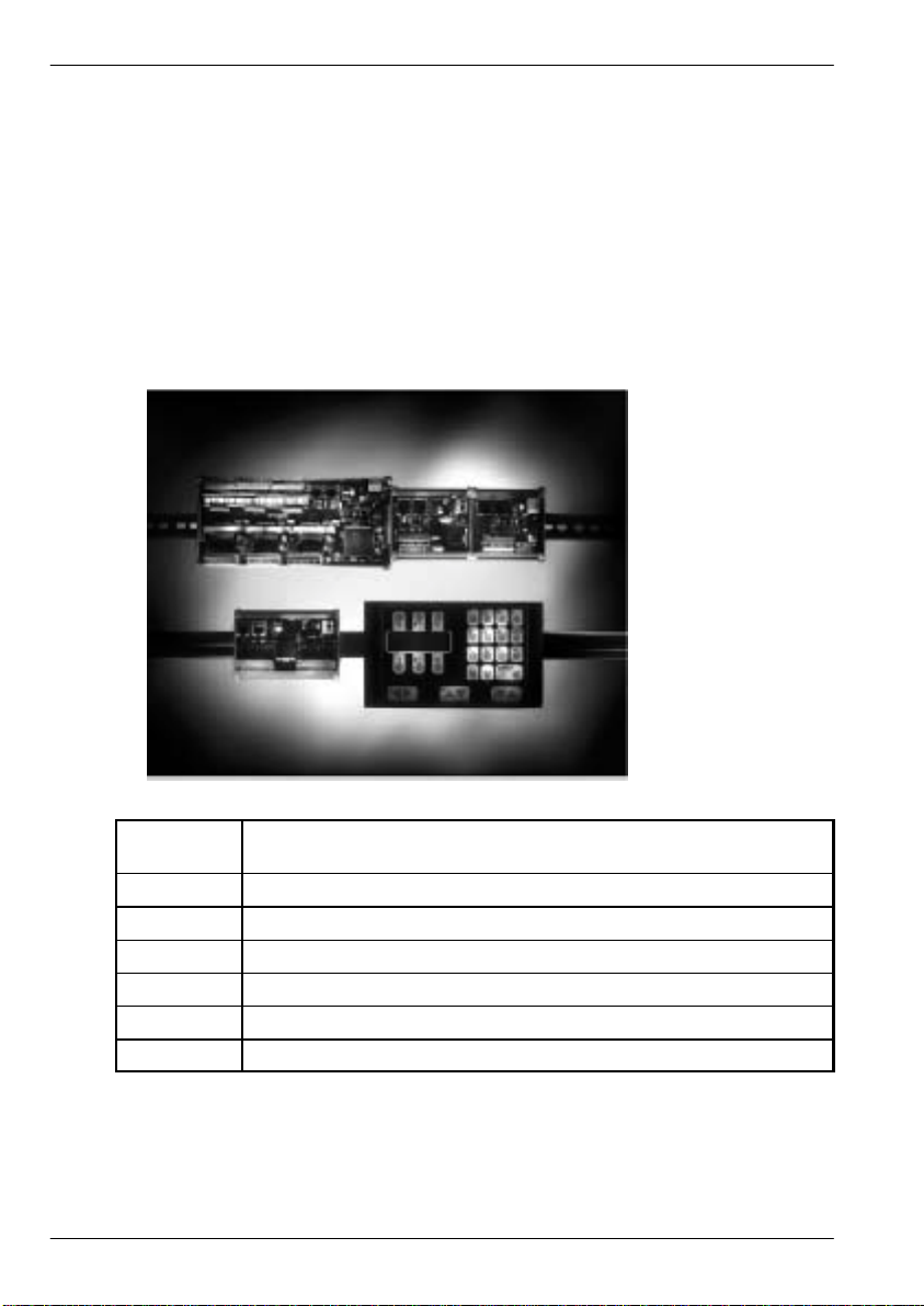
A.1.8 Baldor CAN nodes
Digital I/O can be expanded easily on NextMove PCI using the Baldor CAN (CAN2)
connection. This provides a high speed serial bus interface to a range of I/O devices,
including:
H inputNode 8: 8 opto isolated digital inputs.
H relayNode 8: 8 relay outputs.
H outputNode 8: 8 opto isolated digital outputs with short circuit and over current protection.
H ioNode 24/24: 24 opto isolated input and 24 opto isolated outputs.
H keypadNode: General purpose operator panel (3 and 4 axis versions).
Catalog
number
ION001-503 8 digital inputs
ION002-503 8 relay outputs
ION003-503 8 digital outputs
ION004-503 24 digital inputs and 24 digital outputs
KPD002-502 27 key keypad and 4 line LCD display
KPD002-505 41 key keypad and 4 line LCD display
Description
A-6 Accessories MN1903
Page 89

A.1.9 NextMove PCI CAN Bracket board
This is a compact alternative to using the breakout module when the
NextMove PCI controller is being used only as a CAN network
manager. Both CAN channels are presented on 9-pin D-type
connectors. The board is connected to the NextMove PCI CAN
jumpers by a ribbon cable.
The CAN1 (CANopen) channel is presented on a 9-pin male D-type
connector and is fitted with the isolated CAN transceiver module.
A supply of 12-24V (60mA) must be connected to CAN1 V+ and
CAN1 GND (see section 4.6).
The CAN2 (Baldor CAN) channel is presented on a 9-pin male D-type
and is fitted with the non-isolated CAN transceiver module.
Terminators J4 (Baldor CAN) and J5 (CANopen) are provided for
terminating the CAN networks. There should be terminators at the
both ends of each network and nowhere else.
Catalog
number
OPT030-501
Description
CAN bracket assembly - alternative to breakout module for CAN
connections only
A.1.10 Encoder Splitter/Buffer board
This is a stand alone PCB that takes an encoder signal, either single ended or differential and
gives differential outputs. This is useful for ‘daisy chaining’ an encoder signal from a master
across a number of controllers.
Catalog
number
OPT008-501
OPT029-501
Description
2-way encoder splitter - allows a single-ended or differential encoder pulse
train to be shared between two devices
4-way encoder splitter - allows a single-ended or differential encoder pulse
train to be shared between four devices
Accessories A-7MN1903
Page 90

A-8 Accessories MN1903
Page 91

Page 92

L T0166A00
Baldor Electric Company
P.O. Box 2400
Ft. Smith, AR 72902-2400
Tel: (479) 646-4711
Fax: (479) 648-5792
www.baldor .com
PrintedinUK
E Baldor UK Ltd
 Loading...