

Page 1

Quick Start Guide
MN1944 8/05
IMPORTANT NOTE !
This Quick Start Guide is not in tended as a replacemen t for the full in stallation manual,
MN1942 Micr oFlex e100 Installation Manual, which pr ovides detailed information about the product.
The installation manual is available in PDF format on the supplied Baldor Motion Toolkit CD.
Mounting
MicroFlex e100 is designed to be support ed by four M5 sc rews,
spaced as shown in the diagram.
MicroFlex e100 must be fixed to a s mooth vertical metal surface to
ensure effective cooling.
63.5mm
167.7 mm
LT0228A00
PrintedinUK
© Baldor UK Ltd
Baldor UK Ltd
Mint Motion Centre
6 Bristol Distribution Park
Hawkley Drive
Bristol, BS32 0BF
Visit www.supportme.net for the latest documentation and software releases.
Mounting
hole centers
Cooling for 6A & 9A models
Effective cooling f or the MicroFlex e100 is ess ential:
* The 3A model requires no additional cooling.
* The 6A model requires additional forc ed air cooling at 1.0m/s or greater.
* The 9A model requires additional forc ed air cooling at 2.5m/s or greater.
2
1
Heatsink
Fan
Quoted air veloc ities are for air originating from below the MicroFlex e100,
passing parallel to the heats ink. With MicroFlex e100 mounted as specified,
quoted air velocities allow full driv e rated current at ambient temperatures up
to 45°C.
Page 2
Regeneration resistor (optional)
A suitable r egeneration res istor may be required to
dissipate exc ess power from the internal DC bus
during motor deceleration.
The regenerat ion resistor must have a resistanc e of
at least 39Ω, induc tance of less than 100µH, and a
power rating suitable for the application. B aldor parts
RG56 (44W) or RG 39 (100W) are rec ommended.
Connect the regener ation resistor to R1 and R2.
X1
R1
R2
Motor feedback input
The Micr oFlex e100 can operate with incremental,
SSI, EnDat or SinCos encoder feedback devices.
The device type is configured in Mint WorkBenc h.
Suitable cables are av ailable from Baldor.
Connect the motor feedback signal t o connect or X8.
X8
USB communication
The MicroFlex e100 communicates w ith the host P C
using U SB1.1 communication.
Connect the supplied USB cable between the
MicroFlex e100 and the host PC’s USB port (USB 1.1
or USB2.0).
AC power, fuses and filter
MicroFlex e100 c an acc ept supply voltages of
105-250VAC 50/60Hz , 1-phase or 3 -phase.
For three phase supplies, connec t phases to L1, L2
and L3.
For single phase supplies, connect supply to any two
line inputs , for example L1 and L2.
The AC supply must incorpor ate a circuit breaker (or
fuse) and the specified filter. For ideal earthing, mount
filter on the same metal s urface as MicroFlex e100.
Protective earth must be connected to the
MicroFlex e100 cas e using an M4 scr ew in the top of
the metal heatsink.
X1
L1
L2
L3
Motor U V W outputs
Connect the motor to the U, V and W outputs.
The U, V and W outputs must be c onnected to
their c orresponding U, V or W terminal on the
motor. Misconnection may res ult in uncontrolled
motor mov ement.
Motor earth should be connected to the
MicroFlex e100 case using an M4 sc rew in the
top of the metal heat sink.
The motor cable shield s hould be connected
using a conductiv e earth/ground clamp,
attached to the same metal surface as the
MicroFlex e100.
X1
V
W
U
24VDC control circuit supply
MicroFlex e100 requires a 24VDC (20-30VDC), 1A supply to power the
control electronics.
Connect the c ontrol supply at connector X2.
A fused D C supply should be provided for the MicroFlex e100. If other
devices are to be power ed from the same 24V supply, a filter (Baldor catalog
number FI0014A00) should beins talledto isolate the MicroFlex e100 from the
rest of the system. Alternatively, a ferrite sleeve may be attached to the supply
cable near connec tor X2.
X2
24V
0V
Drive enable input
To enable the MicroFlex e100, 24VDC (12-30VDC)
must be applied to the driv e enable input.
Connect the drive enable signal to pins 9 and 19 of
connector X3.
X3
Drive
enable+
Drive
enable-
3
4
5
6
8
10
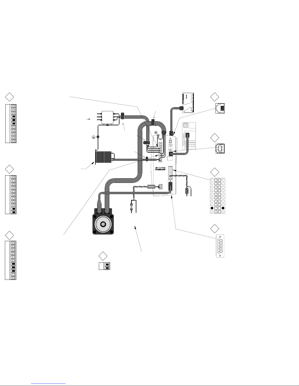
USB
Host PC
AC power
Motor power U V W
USB communication
Control circuit supply.
Use twisted pair cabl e
with a ferrite sleeve.
Motor
+24V 0V
Filter
L1
L2
L1
L2
L3
Star
point
L1
L2
L3
Optional regen resistor
(Dynamic brake)
L3
PE
From
fuses
AC power in
Motor feedback
Regen
Shielded twisted pair, clamped to
metal backplane near drive using
conductive shield earth/ground
clamp.
Connect AC power cable s hield to
metal backplane usi ng conductive
shield clamp.
Connect motor
power cable shield
to metal backplane
using conductive
shield clamp
Drive enable
input
+24V 0V
Ethernet communication
The MicroFlex e100 rec eives demand signals and
sends feedback over the Ethernet based ETHERNET
Powerlink (EPL) connection.
Connect a CAT5 Ethernet cable bet ween the
MicroFlex e100 and an EPL compatible controller
such as NextMove e100. Su itable cables are
available from Baldor.
7
Ethernet
9
NextMovee100
Ferrite
Fuse
 Loading...