

Page 1

Linear Motors
Installation & Operating Manual
1/01 MN1800
Page 2

Table of Contents
Section 1
General Information 1-1. . . . . . . . . . . . . . . . . . . . . . . . . . . . . . . . . . . . . . . . . . . . . . . . . . . . . . . . . . . . . . . . . . . . . . . . . . . . . . .
Overview 1-1. . . . . . . . . . . . . . . . . . . . . . . . . . . . . . . . . . . . . . . . . . . . . . . . . . . . . . . . . . . . . . . . . . . . . . . . . . . . . . . . . . . . .
Limited Warranty 1-1. . . . . . . . . . . . . . . . . . . . . . . . . . . . . . . . . . . . . . . . . . . . . . . . . . . . . . . . . . . . . . . . . . . . . . . . . . . . . . .
Safety Notice 1-2. . . . . . . . . . . . . . . . . . . . . . . . . . . . . . . . . . . . . . . . . . . . . . . . . . . . . . . . . . . . . . . . . . . . . . . . . . . . . . . . . .
Receiving 1-3. . . . . . . . . . . . . . . . . . . . . . . . . . . . . . . . . . . . . . . . . . . . . . . . . . . . . . . . . . . . . . . . . . . . . . . . . . . . . . . . . . . . .
Storage 1-3. . . . . . . . . . . . . . . . . . . . . . . . . . . . . . . . . . . . . . . . . . . . . . . . . . . . . . . . . . . . . . . . . . . . . . . . . . . . . . . . . . . . . . .
Unpacking 1-3. . . . . . . . . . . . . . . . . . . . . . . . . . . . . . . . . . . . . . . . . . . . . . . . . . . . . . . . . . . . . . . . . . . . . . . . . . . . . . . . . . . .
Handling 1-3. . . . . . . . . . . . . . . . . . . . . . . . . . . . . . . . . . . . . . . . . . . . . . . . . . . . . . . . . . . . . . . . . . . . . . . . . . . . . . . . . . . . . .
Section 2
Installation & Operation 2-1. . . . . . . . . . . . . . . . . . . . . . . . . . . . . . . . . . . . . . . . . . . . . . . . . . . . . . . . . . . . . . . . . . . . . . . . . . .
Overview 2-1. . . . . . . . . . . . . . . . . . . . . . . . . . . . . . . . . . . . . . . . . . . . . . . . . . . . . . . . . . . . . . . . . . . . . . . . . . . . . . . . . . . . .
Location 2-1. . . . . . . . . . . . . . . . . . . . . . . . . . . . . . . . . . . . . . . . . . . . . . . . . . . . . . . . . . . . . . . . . . . . . . . . . . . . . . . . . . . . . .
Clean Room 2-1. . . . . . . . . . . . . . . . . . . . . . . . . . . . . . . . . . . . . . . . . . . . . . . . . . . . . . . . . . . . . . . . . . . . . . . . . . . . . . . . . . .
Mounting a Stage to the Machine Base and Payload To Stage 2-1. . . . . . . . . . . . . . . . . . . . . . . . . . . . . . . . . . . . . . .
LMAC Linear Induction Motor 2-2. . . . . . . . . . . . . . . . . . . . . . . . . . . . . . . . . . . . . . . . . . . . . . . . . . . . . . . . . . . . . . . . . . . .
LMBR Series Brush DC Linear Servo Motor 2-3. . . . . . . . . . . . . . . . . . . . . . . . . . . . . . . . . . . . . . . . . . . . . . . . . . . . . . .
LMBL Series 2-4. . . . . . . . . . . . . . . . . . . . . . . . . . . . . . . . . . . . . . . . . . . . . . . . . . . . . . . . . . . . . . . . . . . . . . . . . . . . . . . . . .
Brushless Linear Iron Core Servo Motor 2-4. . . . . . . . . . . . . . . . . . . . . . . . . . . . . . . . . . . . . . . . . . . . . . . . . . . . . .
Modular Magnet Track 2-6. . . . . . . . . . . . . . . . . . . . . . . . . . . . . . . . . . . . . . . . . . . . . . . . . . . . . . . . . . . . . . . . . . . . .
LMCF Series Brushless Linear Cog Free Servo Motor 2-8. . . . . . . . . . . . . . . . . . . . . . . . . . . . . . . . . . . . . . . . . . . . . .
LMNC Moving Coil Type 2-9. . . . . . . . . . . . . . . . . . . . . . . . . . . . . . . . . . . . . . . . . . . . . . . . . . . . . . . . . . . . . . . . . . . . . . . .
LMNM Moving Magnet Type 2-10. . . . . . . . . . . . . . . . . . . . . . . . . . . . . . . . . . . . . . . . . . . . . . . . . . . . . . . . . . . . . . . . . . . . .
LMPY Series Polynoid Linear Motor Holding Option 2-11. . . . . . . . . . . . . . . . . . . . . . . . . . . . . . . . . . . . . . . . . . . . . . . .
LMSS Series Linear Stepper 2-13. . . . . . . . . . . . . . . . . . . . . . . . . . . . . . . . . . . . . . . . . . . . . . . . . . . . . . . . . . . . . . . . . . . .
Roller Bearing Motor 2-13. . . . . . . . . . . . . . . . . . . . . . . . . . . . . . . . . . . . . . . . . . . . . . . . . . . . . . . . . . . . . . . . . . . . . . .
Air Bearing Motor 2-14. . . . . . . . . . . . . . . . . . . . . . . . . . . . . . . . . . . . . . . . . . . . . . . . . . . . . . . . . . . . . . . . . . . . . . . . . .
LMDS Series Dual Axis Linear Stepper Motor 2-15. . . . . . . . . . . . . . . . . . . . . . . . . . . . . . . . . . . . . . . . . . . . . . . . . . . . .
Positioning Stages 2-16. . . . . . . . . . . . . . . . . . . . . . . . . . . . . . . . . . . . . . . . . . . . . . . . . . . . . . . . . . . . . . . . . . . . . . . . . . . . .
Unpacking 2-16. . . . . . . . . . . . . . . . . . . . . . . . . . . . . . . . . . . . . . . . . . . . . . . . . . . . . . . . . . . . . . . . . . . . . . . . . . . . . . . .
Handling and General Guidelines 2-16. . . . . . . . . . . . . . . . . . . . . . . . . . . . . . . . . . . . . . . . . . . . . . . . . . . . . . . . . . . .
Stage Specifications Disclaimer 2-16. . . . . . . . . . . . . . . . . . . . . . . . . . . . . . . . . . . . . . . . . . . . . . . . . . . . . . . . . . . . .
LSE Series 2-17. . . . . . . . . . . . . . . . . . . . . . . . . . . . . . . . . . . . . . . . . . . . . . . . . . . . . . . . . . . . . . . . . . . . . . . . . . . . . . .
LSC Series 2-21. . . . . . . . . . . . . . . . . . . . . . . . . . . . . . . . . . . . . . . . . . . . . . . . . . . . . . . . . . . . . . . . . . . . . . . . . . . . . . .
LSS Series 2-24. . . . . . . . . . . . . . . . . . . . . . . . . . . . . . . . . . . . . . . . . . . . . . . . . . . . . . . . . . . . . . . . . . . . . . . . . . . . . . .
LSX Series 2-26. . . . . . . . . . . . . . . . . . . . . . . . . . . . . . . . . . . . . . . . . . . . . . . . . . . . . . . . . . . . . . . . . . . . . . . . . . . . . . .
Continued on next page
Table of Contents iMN1800
Page 3

Bearing Maintenance 2-31. . . . . . . . . . . . . . . . . . . . . . . . . . . . . . . . . . . . . . . . . . . . . . . . . . . . . . . . . . . . . . . . . . . . . . . . . . .
Recirculating Bearing Rail And Block 2-31. . . . . . . . . . . . . . . . . . . . . . . . . . . . . . . . . . . . . . . . . . . . . . . . . . . . . . . . .
Cross Roller Type Bearing 2-31. . . . . . . . . . . . . . . . . . . . . . . . . . . . . . . . . . . . . . . . . . . . . . . . . . . . . . . . . . . . . . . . . .
Encoder Maintenance 2-32. . . . . . . . . . . . . . . . . . . . . . . . . . . . . . . . . . . . . . . . . . . . . . . . . . . . . . . . . . . . . . . . . . . . . . . . . .
RSF Series MSA6x Enclosed Type 2-32. . . . . . . . . . . . . . . . . . . . . . . . . . . . . . . . . . . . . . . . . . . . . . . . . . . . . . . . . .
RSF Series MS6x Open Type Glass Scale 2-33. . . . . . . . . . . . . . . . . . . . . . . . . . . . . . . . . . . . . . . . . . . . . . . . . . . .
Renishaw RGH22 series Open Type Metal Scale 2-34. . . . . . . . . . . . . . . . . . . . . . . . . . . . . . . . . . . . . . . . . . . . . .
ELGO Mix 4 series Magnetic Type 2-36. . . . . . . . . . . . . . . . . . . . . . . . . . . . . . . . . . . . . . . . . . . . . . . . . . . . . . . . . . .
ELGO Mix 5 series Magnetic Type 2-37. . . . . . . . . . . . . . . . . . . . . . . . . . . . . . . . . . . . . . . . . . . . . . . . . . . . . . . . . . .
Encoder Specifications 2-38. . . . . . . . . . . . . . . . . . . . . . . . . . . . . . . . . . . . . . . . . . . . . . . . . . . . . . . . . . . . . . . . . . . . . . . . .
Cables and Cable Chain Procedures 2-39. . . . . . . . . . . . . . . . . . . . . . . . . . . . . . . . . . . . . . . . . . . . . . . . . . . . . . . . . . . . .
Additional Cables 2-40. . . . . . . . . . . . . . . . . . . . . . . . . . . . . . . . . . . . . . . . . . . . . . . . . . . . . . . . . . . . . . . . . . . . . . . . . . . . . .
ii Table of Contents MN1800
Page 4

Section 1
General Information
Overview This manual contains general procedures that apply to Baldor Linear Motor products. Be sure to read
and understand the Safety Notice statements in this manual. For your protection, do not install, operate
or attempt to perform maintenance procedures until you understand the Warning and Caution statements.
A Warning statement indicates a condition that can cause harm to personnel. A Caution statement
indicates a condition that can cause damage to equipment.
Important: This instruction manual is not intended to include a comprehensive listing of all details for all
procedures required for installation, operation and maintenance. This manual describes general
guidelines that apply to most of the linear motor products shipped by Baldor. If you have a
question about a procedure or are uncertain about any detail, Do Not Proceed. Please contact
your Baldor distributor for more information or clarification.
Before you install, operate or perform maintenance, become familiar with the following:
NEMA Publication MG-2, Safety Standard for Construction and guide
for Selection, Installation and Use of Electric Motors and Generators.
The National Electrical Code
Local codes and practices
Limited Warranty
1. Baldor Electric motors are warranted for a period of one (1) year, from date of shipment from the factory or factory
warehouse against defects in material and workmanship. To allow for stocking and/or fabrication period and to
provide one year of actual service, the warranty period is extended for an additional period of six (6) months for a
total of eighteen (18) months from the original date of shipment from the factory or factory warehouse stock. In no
case will the warranty period be extended for a longer period. Baldor extends this limited warranty to each buyer
of the electric motor for the purpose of resale and to the original purchaser for use.
2. Baldor will, at its option repair or replace a motor which fails due to defects in material or workmanship during the
warranty period if:
a. the purchaser presents the defective motor at or ships it prepaid to, the Baldor plant in Fort Smith, Arkansas
or one of the Baldor Authorized Service Centers and
b. the purchaser gives written notification concerning the motor and the claimed defect including the date
purchased, the task performed by the Baldor motor and the problem encountered.
3. Baldor will not pay the cost of removal of any electric motor from any equipment, the cost of delivery to Fort Smith,
Arkansas or a Baldor Authorized Service Center, or the cost of any incidental or consequential damages resulting
from the claimed defects. (Some states do not allow the exclusion or limitation of incidental or consequential
damages, so the above exclusion may not apply to you.) Any implied warranty given by laws shall be limited to
the duration of the warranty period hereunder. (Some states do not allow limitations on how long an implied
warranty lasts, so the above limitation may not apply to you.)
4. Baldor Authorized Service Centers, when convinced to their satisfaction that a Baldor motor developed defects in
material or workmanship within the warranty period, are authorized to proceed with the required repairs to fulfill
Baldor’s warranty when the cost of such repairs to be paid by Baldor does not exceed Baldor’s warranty repair
allowance. Baldor will not pay overtime premium repair charges without prior written authorization.
5. The cost of warranty repairs made by centers other than Baldor Authorized Service Centers WILL NOT
unless first authorized in writing by Baldor.
6. Claims by a purchaser that a motor is defective even when a failure results within one hour after being placed into
service are not always justified. Therefore, Baldor Authorized Service Centers must determine from the condition
of the motor as delivered to the center whether or not the motor is defective. If in the opinion of a Baldor
Authorized Service Center, a motor did not fail as a result of defects in material or workmanship, the center is to
proceed with repairs only if the purchaser agrees to pay for such repairs. If the decision is in dispute, the
purchaser should still pay for the repairs and submit the paid invoice and the Authorized Service Center’s signed
service report to Baldor for further consideration.
7. This warranty gives you specific legal rights, and you may also have other rights which vary from state to state.
be paid
General Information 1-1MN1800
Page 5

Safety Notice: This equipment contains high voltage! Electrical shock can cause serious or fatal injury.
Only qualified personnel should attempt installation, operation and maintenance of
electrical equipment.
Be sure that you are completely familiar with NEMA publication MG-2, safety standards
for construction and guide for selection, installation and use of electric motors and
generators, the National Electrical Code and local codes and practices. Unsafe
installation or use can cause conditions that lead to serious or fatal injury. Only qualified
personnel should attempt the installation, operation and maintenance of this equipment.
WARNING: The magnetic attraction between the motor and the magnet
assembly is extremely high. Keep fingers and other body parts
away from these objects to avoid injury by this magnetic attraction.
WARNING: Use proper care and procedures that are safe during handling,
lifting, installing, operating and maintaining operations.
Improper methods may cause muscle strain or other harm.
WARNING: Do not touch electrical connections before you first ensure that
power has been disconnected. Electrical shock can cause serious
or fatal injury. Only qualified personnel should attempt the
installation, operation and maintenance of this equipment.
WARNING: Be sure the system is properly grounded before applying power.
Do not apply AC power before you ensure that all grounding
instructions have been followed. Electrical shock can cause
serious or fatal injury. National Electrical Code and Local codes
must be carefully followed.
WARNING: This equipment may be connected to other machinery that has
moving parts that are driven by this equipment. Improper use can
cause serious or fatal injury. Only qualified personnel should
attempt to install operate or maintain this equipment.
WARNING: Do not by-pass or disable protective devices or safety guards.
Safety features are designed to prevent injury to personnel or
damage to equipment. These devices can only provide protection if
they remain operative.
WARNING: Disconnect all electrical power from the motor windings and
accessory devices before disassembly of the motor. Electrical
shock can cause serious or fatal injury.
WARNING: Do not use these motors in the presence of flammable or
combustible vapors or dust. These motors are not designed for
atmospheric conditions that require explosion proof operation.
WARNING: Motors that are to be used in flammable and/or explosive
atmospheres must display the UL label on the nameplate.
Specific service conditions for these motors are defined in
NEC 70-599.
Caution: Be careful when sliding the motor from its shipping container. Slide
the motor from the box onto a level, flat surface to prevent bending.
Bending can damage the windings and commutators.
1-2 General Information MN1800
Page 6

Receiving Each Baldor motor is thoroughly tested at the factory and carefully packaged for
shipment. When you receive your motor, there are several things you should do
immediately.
1. Observe the condition of the shipping container and report any damage
immediately to the commercial carrier that delivered your motor.
2. Verify that the part number of the motor you received is the same as the part
number listed on your purchase order.
Storage If the parts are not put into service immediately, store them in a clean, dry and warm
location. If the storage location is damp or humid, the exposed metal surface of the
motors and windings must be protected from moisture. If the ambient temperature
decreases suddenly, condensation may form. Protect all parts from moisture.
Unpacking Each Baldor motor is packaged for ease of handling and to prevent entry of
contaminants.
1. To avoid condensation inside the motor, do not unpack until the motor has
reached room temperature. (Room temperature is the temperature of the room
in which it will be installed). The packing provides insulation from temperature
changes during transportation.
2. When the motor has reached room temperature, remove all protective wrapping
material from the motor.
3. The magnet track sections may come packaged in one or more boxes. Do not
flip any magnet track sections inside the box. Unpack the magnet track
sections one piece at a time. Place each section on a clean non–magnetic
surface away from other magnet track sections and any other ferrous material.
4. Always keep the magnet track sections at a safe distance from each other. If
the assemblies are to be left unattended for any period of time, precautions
should be taken to prevent accidents due to the strength of the magnets (it is
best to leave them in their packing material to prevent injury due to magnetic
attraction). Persons who will come in contact with this assembly while
receiving, transporting, storing, installing, disassembling or at any other time,
must be made aware of this danger.
Handling Be extremely careful. Keep in mind:
1. The magnetic attraction between the motor and the magnet assembly is
extremely high. Keep fingers and other body parts away from these objects to
avoid injury by this magnetic attraction.
2. Use proper care and procedures that are safe during handling, lifting, installing,
operating and maintaining operations.
Improper methods may cause muscle strain or other harm.
Repairs Baldor will not share any responsibility for damage caused by customer attempt to repair
or modify a motor. Consult Baldor for any service.
For further assistance please contact the factory:
Baldor Linear Motion Products
25026 Anza Drive
Santa Clarita, CA 91355, USA
(661) 257–0216 (phone)
(661) 257–2037 (fax)
General Information 1-3MN1800
Page 7

1-4 General Information MN1800
Page 8

Section 2
Installation & Operation
Overview Installation should conform to the National Electrical Code as well as local codes and
practices. When other devices are coupled to the motor, be sure to install protective
devices to prevent accidents. Machinery that is accessible to personnel should provide
protection in the form of guard rails, screening, warning signs etc.
Location The motor should be installed in an area that is protected from direct sunlight, corrosives,
harmful gases or liquids, dust, metallic particles, welding spatters and vibration.
Exposure to these can reduce the operating life and degrade performance. Be sure to
allow clearance for ventilation and access for cleaning, repair, service and inspections.
Ventilation is extremely important. Be sure the area for ventilation is not obstructed.
Obstructions limit the free passage of air. Motors get warm and the heat must be
dissipated to prevent damage.
These motors are not designed for atmospheric conditions that require explosion proof
operation. They must NOT
or dust.
Clean Room Stages prepared for Class 10, 100 and 10,000 clean room requirements can be ordered
as an option to our standard products. Materials must be suitable for the specified
environment. The customer must perform the final cleaning due to contamination during
shipping and handling.
The most common changes to the stages include the replacement of the bellows,
installation of special greases, elimination of bearing shields and the removal of other
non–critical components that may contribute to particle generation.
Mounting a Stage to the Machine Base and Payload To Stage
S Your stage is provided with mounting holes to attach the stage to a machine base. If
your stage is supplied with bellows, you must remove the bellows to access the
mounting holes. The mounting holes are typically non–threaded, counter–bored
holes that accommodate a variety of screw sizes. It is recommended that a
hardened machine screw be used. Refer to the mechanical drawings provided with
your stage for mounting screw size and hole locations.
S The flatness of your mounting surface will greatly influence the flatness and
straightness specification of your stage. The stage structure will tend to mirror the
flatness of the mounting surface. For the stage to maintain its specification, it must
be mounted to a surface that is flat (maximum error of 0.0005 inches per foot). A
maximum of 0.010 inches per foot is the maximum mounting surface flatness error
allowable for operation of the stage. However, at 0.010 inches per foot mounting
base flatness, the stage flatness and straightness specification will be degraded.
S The mounting surface must be clean and free of particles that could affect flatness
(particles that come between the stage and the mounting surface) . It is also
recommended that the base of the stage be cleaned to remove contamination.
Cleaning with alcohol or acetone is suggested, however avoid submersion or
contamination of the internal components.
S When mounting the payload to the slide assembly, use the same precautions
mentioned for the stage. Refer to the stage outline drawing for hole locations and
specifications.
S When pinning is required, Baldor recommends that the stage be machined and
assembled at the factory.
Note: It is strongly recommended that a thread locking compound be used when
mounting the stage to the base and when mounting the payload to the slide
assembly.
be used in the presence of flammable or combustible vapors
Installation & Operation 2-1MN1800
Page 9
LMAC Linear Induction Motor
General Description: Single or three phase, linear AC induction motor primary.
Construction: Epoxy encapsulated and steel laminated coil assembly (motor primary) Motor secondary
(customer supplied) must conform to the following specifications: 1/8–inch aluminum or
copper plate backed by a
be at least the with of the motor coil assembly.
Maintenance: Motor should be kept dry and relatively free of contamination. This motor is water
resistant, not water proof. Avoid submersion. Avoid contact with petroleum–based
solvents. Alcohol or soapy water can be used to remove contaminants.
Motor specifications: Refer to catalog or outline drawing supplied with motor for mechanical dimensions and
electrical specifications.
Motor Mounting: Your motor may be supplied with either base or foot mounting, refer to catalog or outline
drawing supplied with motor for mounting details and hole dimensions. It is
recommended that all available coil assembly mounting holes be utilized to properly
secure the coil assembly. If the coil is in motion, the motor wires must be strain relieved.
We recommend that the motor secondary be secured with 1/4inch fasteners on the left
and right sides of the secondary, every four to six inches of its length. An air–gap of 1/8
inch is recommended. Refer to linear induction motor duty cycle–force–current curves in
this booklet for information regarding the affects of air–cap size on motor performance.
Electrical Connections For voltage and current specifications, refer to Catalog BR1800 or to documentation
enclosed for custom motors. The 10 foot flying leads can be cut to remove excess length
if required. Connectors are available; contact a Baldor representative for more
information.
For single phase motors, refer to the table supplied with this booklet for capacitor
selection.
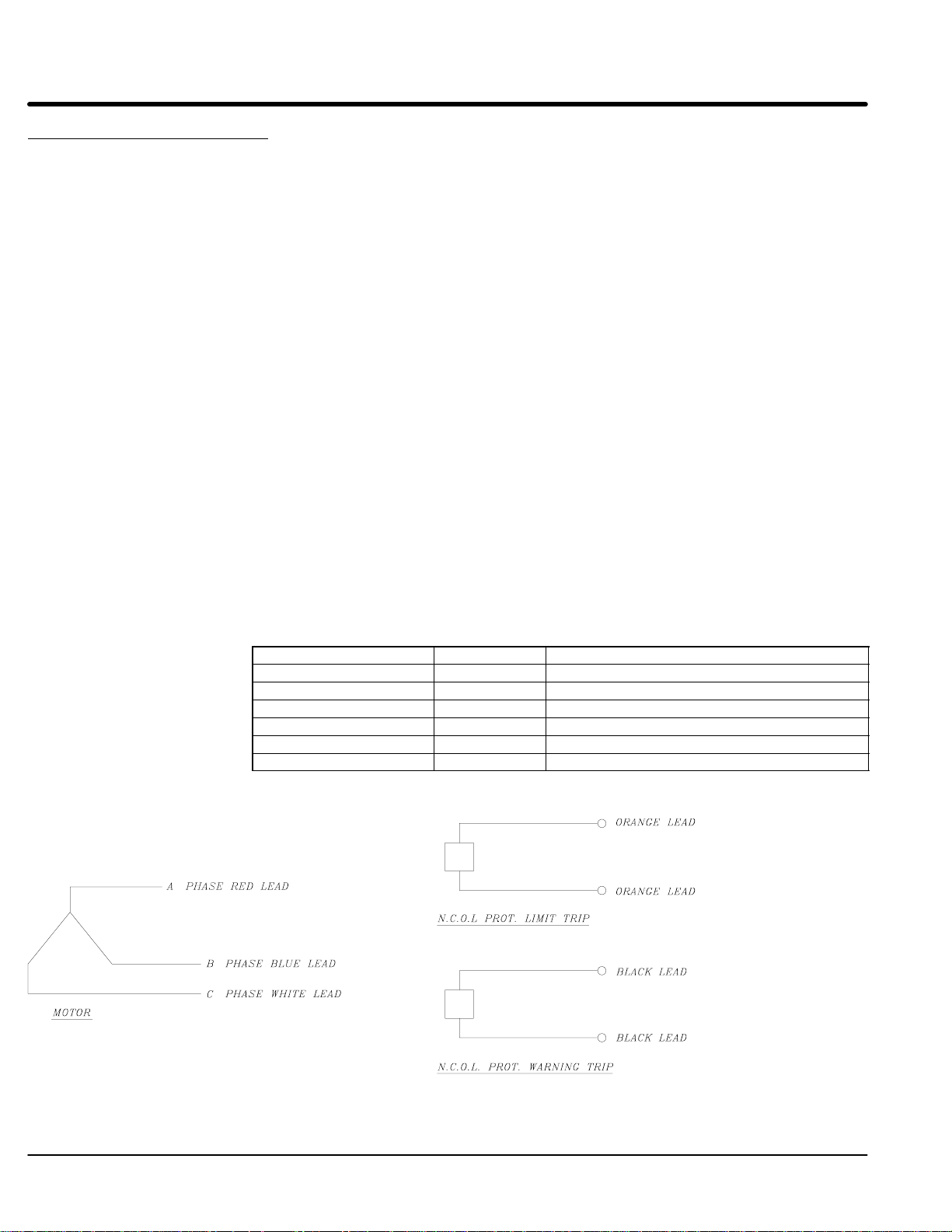
Motor Wire
Function Gauge Color
Phase A 10 Red
Phase B 10 Blue (substituted by black in older models)
Phase C 10 White
Ground Motor housing
Thermal switch 20 Orange (two wires, interchangeable)
Thermal warning 20 Black (two wires, interchangeable)
1/4 inch cold rolled steel plate. The width of the secondary must
LMAC Connection Diagram
2-2 Installation & Operation MN1800
Page 10

LMBR Series Brush DC Linear Servo Motor
Mounting The motor primary must be aligned (parallel) to the equipment guide ways within 0.005″
(0.127mm) on each end. Use gauge blocks and shims as necessary. Precise parallel
alignment of the motor to the equipment guideways is required. Align the stationary half
of the motor to the guideways. Then align the moving half with the stationary half.
When securing the primary to the equipment base do not allow the screws to penetrate
the motor more than .25″ deep (to prevent damage to the motor windings).
To mount the motor secondary, slide the table over the secondary and align the mounting
holes. The secondary is to be secured to the moving table with screws after the proper
amount of shims are added to maintain an air gap of .015″ min. to .020″ max. (unless
otherwise specified) between the secondary and the primary. This is achieved by
ensuring that the plastic shim provided does not bind anywhere over the length of the
primary when moving the table top with secondary back and forth by hand.
The plastic shim between the primary and the secondary can now be removed. Be sure
that the secondary is centered and runs parallel to the commutator to within .005″ at each
end.
Electrical Check: With an ohmmeter across input terminals, verify that the resistance reading does not drop
to zero when the secondary / commutator assembly is moved over the entire length of the
stationary primary. If a zero reading is observed, inspect the connections between the
commutator brushes and the power input wires. In addition, inspect the connections
between the motor windings and the commutator bar.
Motor Removal: Insert the plastic shim between the primary and secondary to maintain the air gap. First,
disconnect the power input wires. Next, remove the screws between the secondary and
the moving table as this allows the secondary to sit on the primary. Then remove the
mounting screws between the primary and the base. Finally, the complete motor
assembly can be removed and placed on a level, flat surface.
Secondary Removal: If just the secondary must be removed,slide the table with the secondary attached, to one
end of the primary. Insert a .015″ minimum plastic shim between the secondary and the
primary to maintain the air gap. Remove the screws between the secondary and the
sliding table. Move the table out of the way and slide the secondary out using extreme
caution so as to not damage the brushes. If brushes are worn out, contact Northern
Magnetics for replacement.
Secondary Reinstallation: Place .015″ minimum plastic shim on primary face. Next place .015″ min fiberglass shims
on the brush assembly and completely depress the brushes into their holders. With the
brushes toward the commutator bars, slide the secondary onto the primary face (with the
shim in place). When the secondary is in place, gently remove the shim from between
the brushes and commutator bars.
Note: Ensure that the shim between commutator and brushes has rounded ends
and that they do not cut the leads to the commutator bars.
Refer to “Mounting” instructions to reinstall.
Brush Motor Connections: – Black / Red (+)
White (–)
Installation & Operation 2-3MN1800
Page 11
LMBL Series
Brushless Linear Iron Core Servo Motor
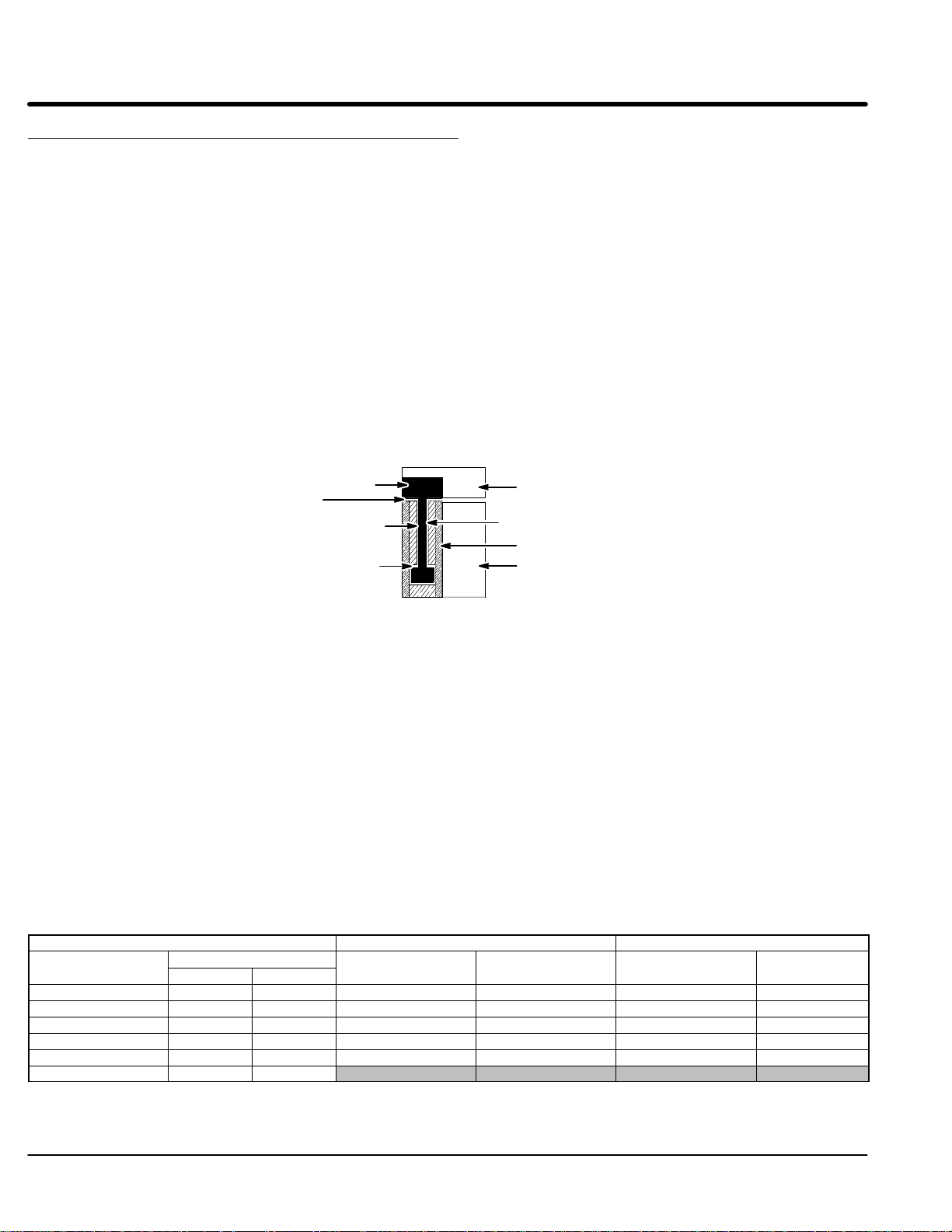
Installation Refer to Figure 2-1.
1. Install the magnet assembly onto the machine mounting base.
2. With the slide assembly removed from the rails, install the coil assembly onto
3. Place a non–magnetic shim over the magnets, sized to cover all the magnets.
4. Install and push the slide along the rails, positioning the coil assembly directly
For either method, it is extremely important to uniformly tighten the mounting screws.
Improper tightening will bend the primary or secondary and damage the motor.
If there is not enough space to install the coil assembly as described, use this alternate
procedure.
Alternate Installation Refer to Figure 2-1.
1. Place the non–magnetic shim on the magnet track.
2. With a firm grip on the coil assembly, place one end of it on the shim and slide it
3. Align the fastening screw holes on the slide with the holes on the coil assembly.
4. Loosely install all the mounting screws.
5. Insert enough shims between the slide and the coil assembly to fill the gap.
6. Tighten all the mounting screws, alternating in a systematic manner while
7. Remove the shim that sets the air gap prior to operation.
Coil Assembly
Magnet
the slide, tightening the mounting screws.
(The shim thickness must be equivalent to the air gap specification. The normal
air gap is 0.030″ ± 0.005″ unless otherwise specified).
over the shim.
(An alternate method is to install the slide on a set of rails that is identical to the
one being used. Butt the temporary rails to the system rails and transfer the
slide onto the system rails.)
into place, centered over the magnets. Be careful not to let the magnet and coil
“Slam” together.
tightening such that the coil assembly is drawn–up evenly leaving a uniform air
gap between the coil assembly and the magnets. This air gap must be
maintained along the entire length of the magnet assembly i.e.; the coil
assembly must never touch the magnets at any point when moving along the
length of the magnet assembly and the air gap specification must be
maintained at all times.
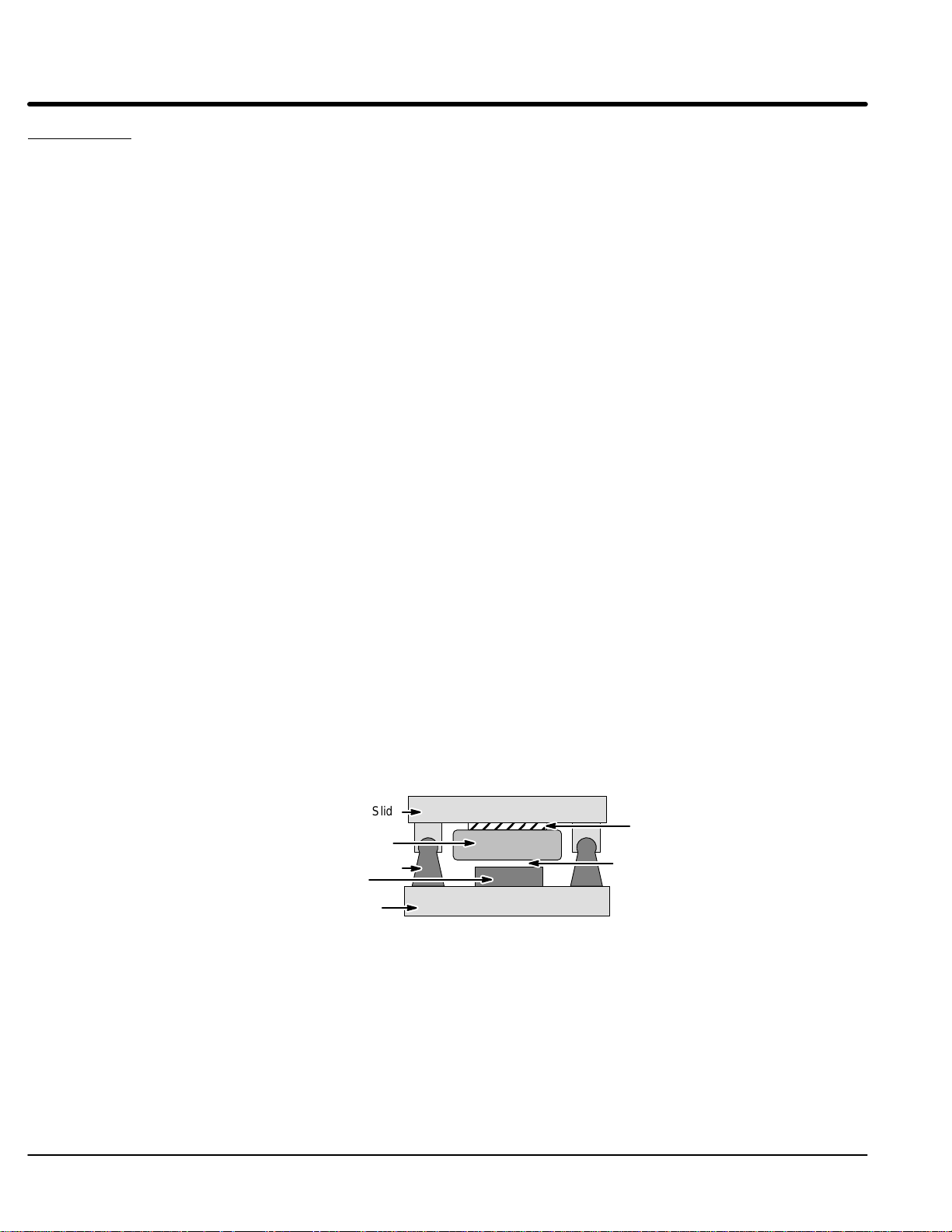
Figure 2-1 Air Gap Adjustment
Slide
Rail
Shim
(if necessary)
Air Gap (0.30 ± 0.005)
Base
2-4 Installation & Operation MN1800
Page 12
LMBL Series Continued
Brushless Linear Iron Core Servo Motor Continued
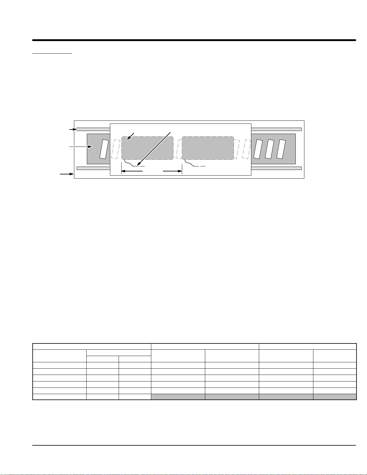
Multiple Coil Assembly Operation
In addition to maintaining an air gap, multiple coil assemblies must also maintain a
spacing factor of 1.8″. In other words, the space between coil assemblies may vary,
however, the distance from the front end of the first coil assembly to the front end of the
next must be a multiple of 1.8″. See Figure 2-2.
Ensure that this spacing is established at the time of installation.
Figure 2-2 Multiple Coil Assemblies
Rail
Magnet
Assembly
Coil Assembly Cable
Base
n (1.8″)
n = 1, 2, 3 , . . .
Operation Considerations The motor must always be operated within the specified operating parameter limits.
Exceeding those limits will permanently damage the motor Refer to the motor
specifications for operating parameter limits.
The motor must never touch the magnets during operation. Refer to “Adjust Air Gap”.
Remove the shim that sets the air gap between the motor and the magnets prior to
operation.
Note: Be aware that the total bearing load includes the magnetic attractive force.
The following steps must be completed to ensure safe and proper operation.
1. Verify that all electrical wiring and cables are properly connected. Refer to the
manual provided with the control for this information.
2. Adjust the control continuous current limit to match the motor’s continuous
current specifications.
3. Adjust the servo drive current to match the motor’s current specification.
4. Refer to the motor specifications for operating parameters. Adjust the control
parameters as necessary to the motor data specifications.
5. Adjust the control for the proper P.I.D. loop tuning. Begin at a low gain setting
and increase the gain as necessary.
6. Strain relieve the wires prior to operating.
AY1763A00 Leadwire Connection
Motor Cable Hall Cable Limit Cable
Signal Name
Motor Phase A (U) Red Black Hall 1 White Limit + Output White
Motor Phase B (V) White Red Hall 2 Red Limit – Output Red
Motor Phase C (W) Black White Hall 3 Black Home Output Black
Motor Ground Green Hall Ground Green Limit & Home PWR * Brown
Thermal Switch+ Blue Hall +5VDC Brown Limit & Home GND Green
Thermal Switch– Orange
Wire Color
LinDrive Trap
Signal Name Wire Color Signal Name Wire Color
* Limit & Home power is +4 to +24VDC.
Note: Motor phasing is for LinDrive or MintDrive. Other controls may require different phasing (such as most trap
drives (U) Black, (V) Red, (W) White). Phase angle between phases is 120 degrees.
Installation & Operation 2-5MN1800
Page 13
LMBL Series Continued
Brushless Linear Iron Core Servo Motor Continued
Modular Magnet Track
Installation Refer to Figure 2-3. Some magnets are provided in modular segments. This is the
recommended procedure to install these modular magnet track sections.
Note: It is recommended that rubber coated tool handles be used to reduce injury
(pinching fingers etc.) and protect the surface of the magnets.
1. Bolt the coil assembly onto the underside of the slide (carriage). Ensure the
leads extend in the proper direction.
2. Install the magnet track on the base–plate adjacent to or between the linear
bearing. Magnet track ends should not oppose each other.
Place a 0.030″ ± 0.005″ thick non magnetic shim on the magnet track. The
shim thickness must be equal to the recommended air gap (space between the
coil assembly and the magnet track).
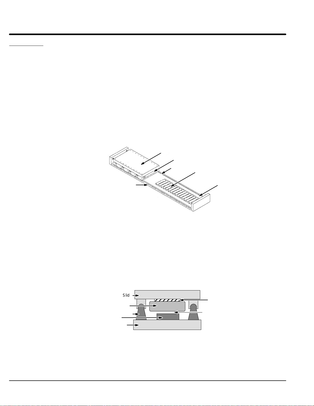
Figure 2-3 Modular Magnet Track Installation
Slide
Coil Assembly
Rail
Install one section of magnet track
Base
Move Slide to this side
after coil is installed
3. Hold the slide with a firm grip and move it over the magnet track section/shim.
Note: The slide will be drawn forcefully towards the magnet track and may
overshoot the rails if not held firmly.
Check the space between the shim and the coil assembly. If the space
between the shim and the coil assembly is large, uniformly loosen the mounting
screws allowing the coil assembly to be fully and evenly lowered onto the shim.
Insert another shim thick enough to fill the gap between the coil assembly and
the slide, see Figure 2-4. Tighten the mounting screws once again.
Figure 2-4 Air Gap Adjustment
Coil Assembly
Magnet
Base
Slide
Rail
Shim
(if necessary)
Air Gap (0.30± 0.005)
2-6 Installation & Operation MN1800
Page 14
LMBL Series Continued
Brushless Linear Iron Core Servo Motor Continued
Modular Magnet Track Continued
4. Install the remaining magnet track sections on the base plate. See Figure 2-5.
5. Remove the air–gap setting shim from the magnet track before use.
Figure 2-5 Modular Magnet Track Installation
Install other section of magnet track with
slide positioned as shown
Guide Rail
Operation Considerations The motor must always be operated within the specified operating parameter limits.
Exceeding those limits will permanently damage the motor Refer to the motor
specifications for operating parameter limits.
The motor must never touch the magnets during operation. The air gap must be
maintained over full length of travel.
Remove the shim that sets the air gap between the motor and the magnets prior to
operation.
Note: Be aware that the total bearing load includes the magnetic attractive force.
The following steps must be completed to ensure safe and proper operation.
1. Verify that all electrical wiring and cables are properly connected. Refer to the
manual provided with the control for this information.
2. Adjust the servo drive current to match the motor’s current specification.
3. Refer to the motor specifications for operating parameters. Adjust the control
parameters as necessary to the motor data specifications.
4. Adjust the control for the proper P.I.D. loop tuning. Begin at a low gain setting
and increase the gain as necessary.
5. Strain relieve the wires prior to operating.
AY1763A00 Leadwire Connection
Motor Cable Hall Cable Limit Cable
Signal Name Wire Color Signal Name Wire Color Signal Name Wire Color
Motor Phase A (U) Red Hall 1 White Limit + Output White
Motor Phase B (V) White Hall 2 Red Limit – Output Red
Motor Phase C (W) Black Hall 3 Black Home Output Black
Motor Ground Green Hall Ground Green Limit & Home PWR * Brown
Thermal Switch+ Blue Hall +5VDC Brown Limit & Home GND Green
Thermal Switch– Orange
* Limit & Home power is +4 to +24VDC.
Note: Motor phasing is for LinDrive or MintDrive. Other controls may require different phasing (such as most trap
drives (U) Black, (V) Red, (W) White). Phase angle between phases is 120 degrees.
Installation & Operation 2-7MN1800
Page 15
LMCF Series Brushless Linear Cog Free Servo Motor
1. Install the coil and magnet assemblies. While mounting the coil, be sure to
adjust coil assembly so it is centered within the magnet assembly with equal air
gap in the vertical and horizontal positions. See Figure 2-6.
2. Verify that the coil assembly is centered within the magnet assembly with equal
air gap in the vertical and horizontal positions along its entire length of travel.
The coil assembly must never be allowed to touch the magnets at any point
from one end of travel to the other.
Note: For modular magnet mounting, magnets are mounted end–to–end without
spacing. The mounting hole pattern is repeating and is unaffected by magnet
segments. Hole pattern repeats across joining ends of magnets.
Multiple Coil Assembly Operation
In addition to maintaining an air gap, multiple coil assemblies must also maintain a
spacing factor of 2.4″. In other words, the space between coil assemblies may vary,
however, the distance from the front end of the first coil assembly to the front end of the
next must be a multiple of 2.4″. See Figure 2-6.
Ensure that this factor is established at the time of installation.
Figure 2-6 Air Gap Spacing
Coil Assembly
Vertical Air Gap
Horizontal Air Gap
Vertical Air Gap
Mounting Plate
Horizontal Air Gap
Magnet Assembly
Machine Base
Operation Considerations The motor must always be operated within the specified operating parameter limits.
Exceeding those limits will permanently damage the motor.
The motor must never touch the magnets during operation. Equal horizontal and vertical
air gap must be maintained.
Remove the shim that sets the air gap between the motor and the magnets prior to
operation.
Note: Be aware that the total bearing load includes the magnetic attractive force.
The following steps must be completed to ensure safe and proper operation.
1. Verify that all electrical wiring and cables are properly connected. Refer to the
manual provided with the control for this information.
2. Adjust the servo drive current to match the motor’s current specification.
3. Refer to the motor specifications for operating parameters. Adjust the control
parameters as necessary to the motor data specifications.
4. Adjust the control for the proper P.I.D. loop tuning. Begin at a low gain setting
and increase the gain as necessary.
5. Strain relieve the wires prior to operating.
AY1763A00 Leadwire Connection
Motor Cable Hall Cable Limit Cable
Signal Name
Motor Phase A (U) Red Black Hall 1 White Limit + Output White
Motor Phase B (V) White Red Hall 2 Red Limit – Output Red
Motor Phase C (W) Black White Hall 3 Black Home Output Black
Motor Ground Green Hall Ground Green Limit & Home PWR * Brown
Thermal Switch+ Blue Hall +5VDC Brown Limit & Home GND Green
Thermal Switch– Orange
Wire Color
LinDrive Trap
Signal Name Wire Color Signal Name Wire Color
* Limit & Home power is +4 to +24VDC.
Note: Motor phasing is for LinDrive or MintDrive. Other controls may require different phasing (such as most trap
drives (U) Black, (V) Red, (W) White). Phase angle between phases is 120 degrees.
2-8 Installation & Operation MN1800
Page 16

LMCF Series Brushless Linear Cog Free Servo Motor Continued
LD9073A00 Hall Sensor Cable Connections (6 pin to flying leads)
Pin# Color Description
1 Black C
2 Red B
3 N.C.
4 Green Ground
5 White A
6 Brown +5VDC
LMNC Moving Coil Type
General Description Bi–directional DC linear motor consisting of a moving wound bobbin assembly and a
stationary magnet assembly. (Refer to catalog BR1800 for motor specifications, if your
motor is custom; refer to documentation included with shipment or contact Baldor).
Construction: Plated steel magnet housing assembly, nylon or like material wound bobbin assembly.
Your motor may or may not be supplied with a mounting flange or other mounting
provisions refer to catalog BR1800 for standard motor specifications or refer to
documentation included with shipment for custom motors.
Bearing type: Bearings are not provided with standard models. It is the purchaser’s responsibility to
supply bearings on standard models. With the magnet assembly secured, the bearing
must support the bobbin assembly so that it is mechanically centered in the magnet
assembly. Failure to center the coil assembly may lead to mechanical contact between
the coil and magnet assembly. If this occurs, motor electrical shorts are possible. If your
motor is supplied with bearings, refer to documentation included with shipment for
additional information. If this additional information is not available, contact your local
Baldor representative for assistance.
Maintenance: Motor should be kept dry and relatively free of contamination. This motor is NOT WATER
PROOF. Avoid submersion. Contact your local Baldor representative for service
information. Avoid contact with petroleum–based solvents. Alcohol can be used to
remove contaminants.
Motor specifications: Refer to catalog or outline drawing supplied with motor for mechanical dimensions and
electrical specifications.
Motor Mounting: Refer to catalog or outline drawing supplied with motor for mounting details and hole
dimensions. If you motor is supplied with drilled and tapped mounting holes, refer to the
recommended seating torque for screws in this document. It is recommended that a
thread locking compound be used with mounting screws. Motor wires must be strain
relieved.
Electrical Connections For voltage and current specifications, refer to Catalog BR1800 for catalog motors or to
documentation enclosed for custom motors. Your motor is supplied with 24 inch flying
leads*. These wires can be cut to remove excess length if required. Connectors are
available; contact a Baldor representative for more information.
Motor Wire
Function Color
– DC Black
+DC White
Ground Motor housing
* Some motors are supplied with custom cables; refer to documentation included with this
shipment for any custom motor designs.
Installation & Operation 2-9MN1800
Page 17

LMNM Moving Magnet Type Non Commutated DC Linear Servo Motor
General Description: Bi–directional DC linear motor with integral bearing. (Refer to catalog BR1 800 for motor
specifications, if your motor is custom; refer to documentation included with shipment or
contact Baldor)
Construction: Anodized aluminum or plated steel housing, aluminum end–caps, steel center shaft.
Your motor may or may not be supplied with a mounting flange or other mounting
provisions refer to catalog BR1 800 for standard motor specifications or refer to
documentation included with shipment for custom motors.
Bearing type: Depending on motor catalog number the bearing may be one of the following: linear, anti
rotational linear, rulon, sapphire, or flexure. Refer to catalog BR1 800. If your motor is
custom, refer to documentation included with shipment. Maintenance: Motor should be
kept dry and relatively free of contamination. This motor is NOT WATER PROOF. Avoid
submersion. These motors are factory assembled and aligned, the bearings must be
serviced by Baldor or a Baldor authorized repair center. Disassembly of motor will void
warranty. Avoid contact with petroleum based solvents. Alcohol can be used to remove
contaminants. Contact your local Baldor representative for service information.
Motor specifications: Refer to catalog or outline drawing supplied with motor for mechanical dimensions and
electrical specifications.
Motor Mounting: Refer to catalog or outline drawing supplied with motor for mounting details and hole
dimensions. When attaching payload to motor, avoid axial loading of the motor shaft.
Axial loading can damage the bearing thus reducing its life. If your motor is supplied with
drilled and tapped mounting holes, refer to the recommended seating torque for screws in
this document. It is recommended that a thread locking compound be used with
mounting screws.
Electrical Connections For voltage and current specifications, refer to Catalog BR1800 or to documentation
enclosed for custom motors. Your motor is supplied with 24 inch flying leads*. These
wires can be cut to remove excess length if required. Connectors are available; contact a
Baldor representative for more information.
Motor Wire
Function Color
– DC Black
+DC White
Ground Motor housing
Thermal switch Orange and Blue pair
(optional on some models)
*If your motor was supplied with custom cables; refer to enclosed documentation for any
custom motor designs.
2-10 Installation & Operation MN1800
Page 18

LMPY Series Polynoid Linear Motor Holding Option
Mounting: The rectifier package is wired externally in the stator circuit.
For 115/60Hz, rectifier package CO0126A00 is provided.
For 230/60Hz, rectifier package CO0125A00 is provided.
Rated holding force is only achieved when the keeper plate is against the holding coil. To
reduce shock loads, a shock absorbing connection between the polynoid rod and the load
is recommended.
Switching: Two switching modes can be used for various applications.
Single Holding:
Energized constantly except momentary interruption to release holding so rod
can be reversed.
Energized only during period when holding is required.
Energized only when rod is moving towards the holding end of the stator and
during the holding period.
Double Holding:
Energized constantly except momentary interruption to release holding so rod
can be reversed.
Energized only during period when holding is required.
Double holding coils may be switched together or one at a time.
Note: Double holding coil units are normally supplied with 2 yellow leads and one
small diameter black lead so that the holding coils may be operated
independently by applying rated voltage to the yellow and black lead. The wire
marker on one yellow lead indicates the lead that operates the holding coil on
the lead egress end of the stator. If desired, the 2 yellow leads can be tied
together for simultaneous operation of both holding coils.
WIRING GUIDES:
1. Single Holding
:
Installation & Operation 2-11MN1800
Page 19

LMPY Series Continued
Polynoid Linear Motor Holding Option Continued
Operation Considerations The motor must always be operated within the specified operating parameter limits.
Exceeding those limits will permanently damage the motor.
Note: Rod should not support axial loads that can induce premature bearing failure.
The following steps must be completed to ensure safe and proper operation.
1. Verify that all electrical wiring and cables are properly connected. Refer to the
manual provided with the control for this information.
2. If using a control, adjust the control continuous current limit to match the
motor’s continuous current specifications.
3. Adjust the control peak current limit so it will not exceed the motor’s peak
current specification.
Leadwire Connection
Motor Cable
Signal Name Wire Color
Motor Phase A Black
Motor Phase B Red
Motor Phase C White
Mounting Instructions Refer to the outline drawing (supplied with motor) for hole dimensions and mounting
information. When attaching the payload to the motor, avoid axial loading of the motor
shaft. Axial loading can damage the rulon bearing.
2-12 Installation & Operation MN1800
Page 20

LMSS Series Linear Stepper
Roller Bearing Motor
Installation Prior to placing the Forcer on the Platen both surfaces must be cleaned. Use this
method:
1. Apply masking tape to lamination surface of the Forcer to remove any metallic
contaminants.
2. Using alcohol, clean both surfaces to remove any adhesive residue and any
other contaminants on the Forcer and the Platen.
Note: Apply small amount of alcohol to cloth for cleaning. Never pour or drip alcohol
or other chemicals onto the forcer or platen surfaces.
3. Wax and polish Platen and Forcer surfaces. ( Turtle Wax ). Remove any visible
residue.
Adjust Air Gap Factory preset to 0.0015″.
Note: When receiving the Forcer and the Platen, the air gap is already set to
0.0015″. (Increasing the air gap will decrease the force). Use the following
instructions only if you need to reset the air gap.
1. Carefully remove the Forcer from the platen by sliding off the Forcer of the end
of the Platen. (So as not to score the Forcer and the Platen surfaces).
2. Loosen the four screws (1 turn) on the bearing kits using an Allen key.
3. Center the shim on the toothed section of the Platen.
4. Place the Forcer on the Platen. Be sure that the shim is only between the
Forcer and the Platen, and not between the wheels and the Platen.
5. Apply downward pressure on both bearing kits only (the Forcer is attached
magnetically) and then tighten the four screws to 30 in–lbs of torque.
6. Slide the Forcer down the Platen while holding the shim in place and remove
the shim.
Maintenance Waxing of the Forcer lamination for corrosion protection is recommended every month (or
as needed) depending on environmental conditions (i.e. humidity and moisture).
Operation Considerations The motor must always be operated within the specified operating parameter limits.
Exceeding those limits will permanently damage the motor.
The forcer must never touch the platen during operation. Equal horizontal and vertical air
gap must be maintained.
The following steps must be completed to ensure safe and proper operation.
1. Verify that all electrical wiring and cables are properly connected. Refer to the
manual provided with the control for this information.
2. Adjust the stepper driver current to match the motor’s current specification.
3. Strain relieve the wires prior to operating.
AY0165A00 Leadwire Connection (9 pin to flying leads)
Color Pin# Description
White 1 A1+ Winding
2 N.C.
Green 3 B1+ Winding
4 N.C.
Black 5 Ground
6 N.C.
Red 7 A1– Winding
8 N.C.
Orange 9 B1– Winding
6
7
8
9
Male (D Sub)
When a Male D Sub connector is used, use the pin numbers to connect the forcer.
1
2
3
When flying leads are used, use the color codes to connect the forcer.
4
5
Installation & Operation 2-13MN1800
Page 21

LMSS Series Continued
Air Bearing Motor
Cleaning the Forcer and Platen
Prior to placing the Forcer on the Platen both surfaces must be cleaned.
Use this method:
1. Apply masking tape to lamination surface of the Forcer. Removing the tape
removes large particle contaminants.
2. Using alcohol, clean both surfaces to remove any adhesive residue and any
other contaminants on the Forcer and the Platen.
Note: Apply small amount of alcohol to cloth for cleaning. Never pour or drip alcohol
or other chemicals onto the forcer or platen surfaces.
3. Wax and polish Platen and Forcer surfaces. ( Turtle Wax ). Remove any visible
residue.
Cleaning the Air Bearings Required if the forcer is not lifting between 0.0005″ – 0.001″ ( i.e. rubbing on the Platen ).
1. Using a small screw driver, unscrew one air bearing.
2. Blow compressed air through the bearing in both directions.
3. Screw the air bearing back to its original position.
Note: Do not mix the air bearings, they have to be installed at their original position.
Installation: Mounting the Forcer on the Platen
1. Before placing the forcer on the platen be sure there is at least 60 psi of
regulated and filtered air flowing through the forcer.
2. At one end of the platen, carefully slide the Forcer onto the Platen.
(BE EXTREMELY CAREFUL ).
Removing the Forcer from the Platen
1. Before moving the forcer, be sure there is at least 60 psi of regulated and
filtered air flowing through the forcer.
2. Carefully slide the Forcer to one end of the Platen and remove it.
(Be Extremely Careful).
Maintenance Waxing of the Forcer lamination for corrosion protection is recommended every month (or
sooner) depending on environmental conditions (i.e. humidity and moisture).
Operation Considerations The motor must always be operated within the specified operating parameter limits.
Exceeding those limits will permanently damage the motor.
The forcer must never touch the platen during operation. Equal horizontal and vertical air
gap must be maintained.
The following steps must be completed to ensure safe and proper operation.
1. Verify that all electrical wiring and cables are properly connected. Refer to the
manual provided with the control for this information.
2. Adjust the stepper driver current to match the motor’s current specification.
3. Strain relieve the wires prior to operating.
LD9145A00 9 pin Female to flying leads LD9147A00 25 pin Female to flying leads
Color Pin# Description
Red 1 A+ Winding
Green 2 A– Winding
Yellow 3 B+ Winding
Orange 4 B– Winding
Black 5 Ground
Blue 6 C+ Winding
Green 7 C– Winding
White 8 D+ Winding
Black 9 D– Winding
Use twisted pairs, shield is open at backshell.
Color Pin# Description
Red 1 1A+ Winding
Green 2 1A– Winding
Yellow 3 1B+ Winding
Orange 4 1B– Winding
Blue 5 1C+ Winding
Green 6 1C– Winding
White 7 1D+ Winding
Black 8 1D– Winding
Black 13 1Ground
Use twisted pairs, shield is open at backshell.
Color Pin# Description
Red 14 2A+ Winding
Green 15 2A– Winding
Yellow 16 2B+ Winding
Orange 17 2B– Winding
Black 18 2C+ Winding
Blue 19 2C– Winding
Green 20 2D+ Winding
White 21 2D– Winding
Black 13 2Ground
2-14 Installation & Operation MN1800
Page 22

LMDS Series Dual Axis Linear Stepper Motor
Items Required but NOT
1. A regulated 80 PSI air supply with a 5 micron filter for each motor.
A water separator is also required.
2. Two or four phase, 2 ampere (micro) stepper motor driver/controller for each motor.
Cleaning the Forcer and Platen
Cleaning the Air Bearings Required if the forcer is not lifting between 0.0005″ – 0.001″ ( i.e. rubbing on the Platen ).
Installation: Mounting the Forcer on the Platen
Maintenance Waxing of the Forcer lamination for corrosion protection is recommended every month (or
Operation Considerations The motor must always be operated within the specified operating parameter limits.
Included
Prior to placing the Forcer on the Platen both surfaces must be cleaned.
Use this method:
1. Apply masking tape to lamination surface of the Forcer. Removing the tape
removes large particle contaminants.
2. Using alcohol, clean both surfaces to remove any adhesive residue and any
other contaminants on the Forcer and the Platen.
Note: Apply small amount of alcohol to cloth for cleaning. Never pour or drip alcohol
or other chemicals onto the forcer or platen surfaces.
3. Wax and polish Platen and Forcer surfaces. ( i.e. Turtle Wax ). Remove any
visible residue.
1. Using a small screw driver, unscrew one air bearing.
2. Blow compressed air through the bearing in both directions.
3. Screw the air bearing back to its original position.
Note: Do not mix the air bearings, they have to be installed at their original position.
1. Before placing the forcer on the platen be sure there is at least 60 psi of
regulated and filtered air flowing through the forcer.
2. Use the lifting tool (in reverse) to gently, place the forcer on the platen. Be
careful not to place your fingers between forcer and platen.
Removing the Forcer from the Platen
1. Before moving the forcer, be sure there is at least 60 psi of regulated air supply
with a 5 µm air filter flowing through the forcer.
2. Place lifting tool (provided) in slot on the side of the forcer. Gently, pry the
forcer from the platen with the tool. Lift the forcer and remove it from the
platen. Be careful not to place your fingers between forcer and platen.
as needed) depending on environmental conditions (i.e. humidity and moisture).
Exceeding those limits will permanently damage the motor.
The following steps must be completed to ensure safe and proper operation.
1. Verify that all electrical wiring and cables are properly connected. Refer to the
manual provided with the control for this information.
2. Adjust the stepper driver current to match the motor’s current specification.
3. Strain relieve the wires prior to operating.
Installation & Operation 2-15MN1800
Page 23

Leadwire Connection
LD9068A00
Color Pin# Description (2 Phase 9 pin to flying leads)
Red 1 (X) A+ Winding
Green 2 (X) A– Winding
Yellow 3 (X) B+ Winding
Orange 4 (X) B– Winding
Black 5 Ground
Blue 6 (Y) A+ Winding
Green 7 (Y) A– Winding
White 8 (Y) B+ Winding
Black 9 (Y) B– Winding
Use twisted pair wires. Shield open at shell.
LD9074A00
Color Pin# Description (2 Phase 25 pin pin to flying leads)
Red 1 (X) A+ Winding
Green 2 (X) A– Winding
Yellow 3 (X) B+ Winding
Orange 4 (X) B– Winding
Black 13 Ground
Blue 14 (Y) A+ Winding
Green 15 (Y) A– Winding
White 16 (Y) B+ Winding
Black 17 (Y) B– Winding
Use twisted pair wires. Shield open at shell.
6
7
8
9
Female (D Sub)
14
15
16
17
18
19
20
21
22
23
24
25
Female (D Sub)
1
2
3
4
5
LD9092A00 (4 Phase 25 pin pin to flying leads)
X–Axis Connections
1
2
Color Pin# Description
3
Red 1 A+ Winding
4
Green 2 A– Winding
5
Yellow 3 B+ Winding
6
Orange 4 B– Winding
7
Blue 5 C+ Winding
8
9
Green 6 C– Winding
White 7 D+ Winding
10
11
Black 8 D– Winding
12
Black 13 Ground
13
Use twisted pair wires.
Shield open at shell.
Y–Axis Connections
Color Pin# Description
Red 14 A+ Winding
Green 15 A– Winding
Yellow 16 B+ Winding
Orange 17 B– Winding
Blue 18 C+ Winding
Green 19 C– Winding
White 20 D+ Winding
Black 21 D– Winding
Black 13 Ground
Use twisted pair wires.
Shield open at shell.
Positioning Stages
Unpacking Observe the condition of the shipping container and report any damage immediately to
the commercial carrier that delivered your stage. Carefully remove the positioning stage
from the shipping crate or box. Inspect the stage and report any evidence of damage to
your local Baldor sales office or authorized distributor. Save the shipping container for
future transportation.
Handling and General Guidelines Be sure to observe the following guidelines:
1. Carefully set the positing stage in place. Do not drop a positioning stage onto
the mounting surface or machine base as this can result in internal damage to
bearing and drive components.
2. Do not drill holes in a positing stage. Contact Baldor if holes must be added.
3. Avoid impact loads such as hammering and punching which may cause internal
damage to bearing and drive components.
4. Avoid submersion in liquids of all types.
5. Do not disassemble the positioning stage as this may void the product warranty.
Stage Specifications Disclaimer
Positioning stage specifications are dependant on the three following variables:
Temperature: Catalog specifications are measured at 25 degrees Celsius.
Measurements of performance at other temperatures may yield different measurements.
Minimum ambient operating temperature: 5 degrees Celsius. Maximum ambient
operating temperature: 75 degrees Celsius. The positioning stage can be modified by
Baldor to allow the unit to be operated at temperatures outside of this range. Contact
Baldor for more information.
Point of measurement: Catalog specifications are measured 25mm above the slide
mounting surface. If measurements are taken from other relative locations, results may
be different from the catalog specifications.
Mounting surface: Catalog specifications are measured with the positioning stage
supported under its entire length, fastened down (bolted) and is mounted to a machine
base that has a maximum flatness error of 0.0005”/ft.
2-16 Installation & Operation MN1800
Page 24

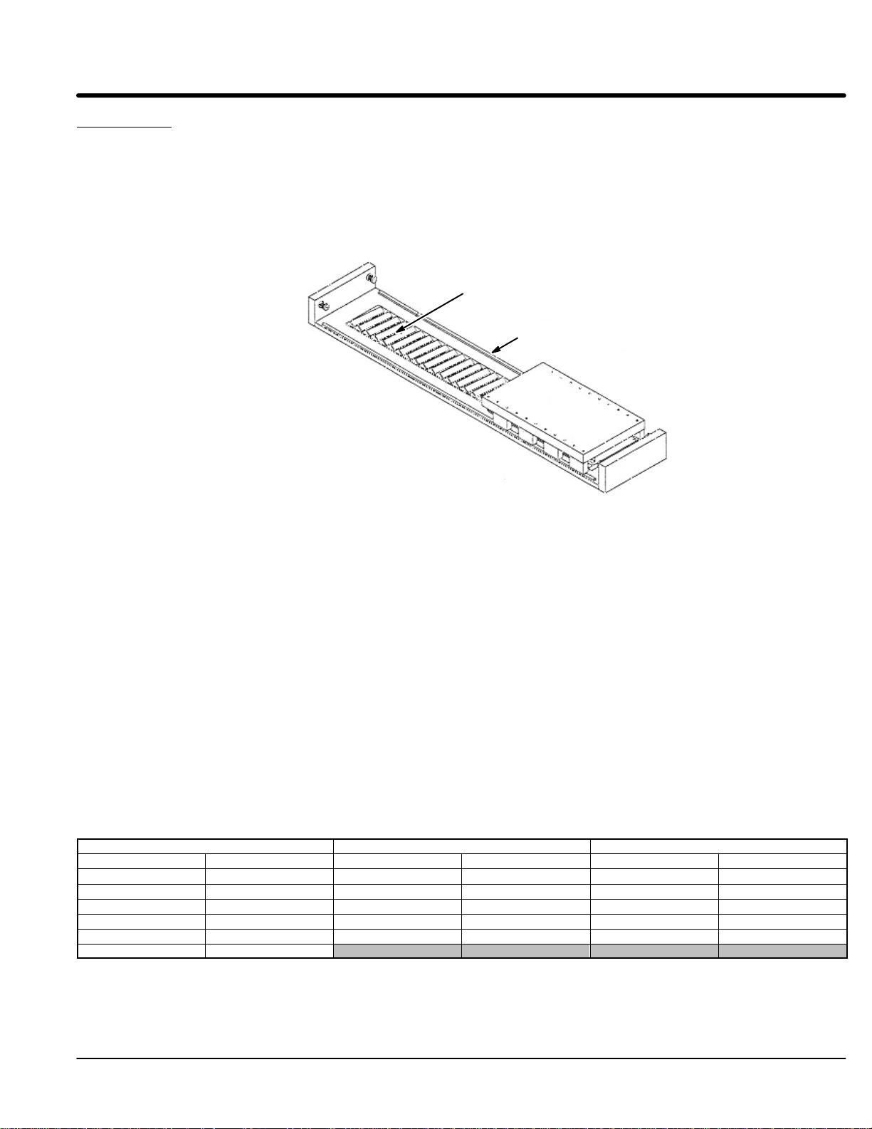
LSE Series Enclosed Position Stage
General Description: Single axis linear stage with linear motor, linear bearings, linear encoder, limit switches,
cable carrier, and bellows
Construction: Hard anodized aluminum
Bearing type: Recirculating ball linear bearing
Encoder type: Open glass scale, optical, magnetic
Motor type: Brushless three phase, iron core or cog free type linear motor. Refer to catalog for motor
specifications and stage model number description. Brush type DC linear motors
available upon request.
Maintenance: Refer to bearing and encoder maintenance recommendations in this manual. Exterior of
stage should be kept dry and relatively free of contamination. This stage is NOT WATER
PROOF. Avoid submersion.
Stage specifications: Refer to catalog or outline drawing supplied with stage for mechanical dimensions.
Stage Mounting: Removal of bellows is required for access to base mounting holes. Refer to mounting
recommendations.
ELECTRICAL CONNECTIONS (cables labeled accordingly)
Encoder: Refer to Encoder connections.
Motor/hall/limit switches: Your stage has flying leads 10 foot in length. These cables can be cut if required.
Connectors are available, contact Baldor for more information.
AY1763A00 Leadwire Connection
Motor Cable Hall Cable Limit Cable
Signal Name
Motor Phase A (U) Red Black Hall 1 White Limit + Output White
Motor Phase B (V) White Red Hall 2 Red Limit – Output Red
Motor Phase C (W) Black White Hall 3 Black Home Output Black
Motor Ground Green Hall Ground Green Limit & Home PWR * Brown
Thermal Switch+ Blue Hall +5VDC Brown Limit & Home GND Green
Thermal Switch– Orange
Wire Color
LinDrive Trap
Signal Name Wire Color Signal Name Wire Color
* Limit & Home power is +4 to +24VDC.
Note: Motor phasing is for LinDrive or MintDrive. Other controls may require different phasing (such as most trap
drives (U) Black, (V) Red, (W) White). Phase angle between phases is 120 degrees.
AY1780A00 Leadwire Connection for MintDrive (9 pin to flying leads)
Color Pin# Description
Brown 1 +5VDC
Pink 2 C+
Red 3 B–
Inner Shield 4 Inner Shield
Green 5 A+
Gray 6 C–
White 7 0V
Blue 8 B+
Yellow 9 A–
6
7
8
9
Male (D Sub)
Outer shield to shell.
1
2
3
4
5
Installation & Operation 2-17MN1800
Page 25

AY1775A00 LSE, Encoder (RGH24) & Hall Connections for LinDrive/MintDrive (15 pin to flying leads)
Color Pin# Description
Green 1 A+
Blue 2 B+
Pink 3 C+
White 4 Hall1
5 N/C
Yellow 6 A–
Red 7 B–
Gray 8 C–
Black 9 Hall3
Red 10 Hall2
Brown 11 +5VDC (Halls Brown)
12 N/C
White 13 Encoder GND (Halls Green)
14
15
11
12
13
14
15
Male (D Sub)
Outer shield to shell.
Inner shield to pin 13.
1
2
3
4
5
AY1779A00 LSE with Renishaw Encoder (RGH24) Flying Leads
10 ft cable for use with Renishaw RGH24.
Flying leads are color coded as shown in this diagram.
Cable 1
(Hall Cable)
Cable 2
(Motor Cable)
* Limit & Home power is +4 to +24VDC.
Cable 4
(RGH24
Encoder Cable)
Cable 3
Limit Cable
Cable
1
1
1
1
1
1
1
2
2
2
2
2
2
2
3
3
3
3
3
3
4
4
4
4
4
4
4
4
4
4
Conductor
A
B
C
D
E
F
G
A
B
C
D
E
F
G
A
B
C
D
E
F
A
B
C
D
E
F
G
H
I
J
Signal Name
Hall 3 (C)
Hall 2 (B)
N/C
Hall Ground
Hall 1 (A)
Voltage IN (+5VDC)
Shield
Motor Phase A (U)
Motor Phase B (V)
Motor Phase C (W)
Motor Ground
Thermal Switch +
Thermal Switch -
Shield
Limit/Home Ground
Home Output
Limit + Output
Shield
Limit & Home PWR *
Limit - Output
Signal A+
Signal ASignal B+
Signal BSignal C+
Signal C-
+5VDC
0VDC
Outer Shield
Inner Shield
Color
Black
Red
N/C
Blue, Green or Yellow
White
Brown or Violet
Red
White
Black
Green
Orange
Blue
Blue, Green or Yellow
Black
White
Brown
Red
Green
Yellow
Blue
Red
Pink
Gray
Brown
White
Note: Motor phasing is for LinDrive or MintDrive. Other controls may require different phasing (such as most trap
drives (U) Black, (V) Red, (W) White). Phase angle between phases is 120 degrees.
External Connections
LD9127A00 Leadwire Connection Limit/Home Switch Interface (6 pin to flying leads)
Color Pin# Description
Black 1 Home Output
White 2 Limit+ Output
Red 3 Limit– Output
Green 4 Ground
Brown 5 Limit & Home PWR *
Orange 6 Series / Parallel (Jumper 6 to 3=Series,
Jumper 6 to 5=Parallel)
* Limit & Home power is +4 to +24VDC.
6 3
5 2
4 1
(Connector viewed from cable side)
Jumper pin 3 to pin 6 for Series operation.
Jumper pin 5 to pin 6 for Parallel operation.
(Series jumper option is for Omron 670/671P limits only).
2-18 Installation & Operation MN1800
Page 26

Internal Connections
Leadwire Connection Limit Switch Pigtails
LD9125A01 Limit only
Color Pin# Description
Brown 1 Limit & Home power *
2 N/C
White 3 Limit Output
Green 4 Ground
* Limit & Home power is +4 to +24VDC.
Limit
OUT
671P
4
L
3
2
1
LD9125A02 Limit and Home
Color Pin# Description
Brown 1 Limit & Home power *
Black 2 Home Output
Red 3 Limit Output
Green 4 Ground
* Limit & Home power is +4 to +24VDC.
LD9137A01 Limit only
Color Pin# Description
Brown 1 Limit & Home power *
2 N/C
Black 3 Limit Output
Blue 4 Ground
* Limit & Home power is +4 to +24VDC.
LD9137A02 Limit and Home
Color Pin# Description
Brown 1 Limit & Home power *
Black 2 Home Output
Black 3 Limit Output
Blue 4 Ground
* Limit & Home power is +4 to +24VDC.
L
OUT
Limit
Home
HomeH–Limit
4
671P
OUT
671P
L
3
2
1
Limit
4
3
2
1
4
3
2
LD9124A00 Limit and Home, Axis 1, Internal
Connect to Limit Pigtail
Pin# Color
1 Brown
2
3 White
4
3
2
1
4 Green
Pin# Color
1 Brown
2 Black
3 Red
4
3
2
1
4 Green
Connect to Limit/Home Pigtail
1
Pin# Color
6
3
5
2
4
1
1 Black
2 White
3 Red
4 Green
5 Brown from LD9125A02
6 Brown from LD9125A01
Installation & Operation 2-19MN1800
Page 27

LSE Stage Connector Locations
Home Limit
LD9123A00
LD9125A02
LD9124A00
LD9125A01
Limit
2-20 Installation & Operation MN1800
Page 28

LSC Series Cross Roller Position Stage
General Description: Single axis linear stage with linear motor, linear bearings, linear encoder, limit switches,
cable carrier (on some models), and bellows
Construction: Hard anodized aluminum, black oxide steel
Bearing type: Cross roller linear bearing
Encoder type: Open glass scale if internal, or enclosed type if external
Motor type: Brushless three phase, iron core or cog free type linear motor. Refer to catalog for motor
specifications and stage model number description. Brush type DC linear motors
available upon request.
Maintenance: Refer to bearing and encoder maintenance recommendations in this manual. Exterior of
stage should be kept dry and relatively free of contamination. This stage is NOT WATER
PROOF. Avoid submersion.
Stage specifications: Refer to catalog or outline drawing supplied with stage for mechanical dimensions.
Stage Mounting: Removal of bellows is required for access to base mounting holes. Refer to mounting
recommendations.
ELECTRICAL CONNECTIONS (cables labeled accordingly)
Encoder: Refer to RGH24 series internal encoder connections or MSA6x series external encoder
connections in this manual.
Motor/hall/limit switches: Your stage has flying leads 10 foot in length. These cables can be cut if required.
Connectors are available, contact Baldor for more information.
AY1763A00 Leadwire Connection
Motor Cable Hall Cable Limit Cable
Signal Name
Motor Phase A (U) Red Black Hall 1 White Limit + Output White
Motor Phase B (V) White Red Hall 2 Red Limit – Output Red
Motor Phase C (W) Black White Hall 3 Black Home Output Black
Motor Ground Green Hall Ground Green Limit & Home PWR * Brown
Thermal Switch+ Blue Hall +5VDC Brown Limit & Home GND Green
Thermal Switch– Orange
Wire Color
LinDrive Trap
Signal Name Wire Color Signal Name Wire Color
* Limit & Home power is +4 to +24VDC.
Note: Motor phasing is for LinDrive or MintDrive. Other controls may require different phasing (such as most trap
drives (U) Black, (V) Red, (W) White). Phase angle between phases is 120 degrees.
AY1780A00 Leadwire Connection for MintDrive (9 pin to flying leads)
Color Pin# Description
Brown 1 +5VDC
Pink 2 C+
Red 3 B–
Inner Shield 4 Shield
Green 5 A+
Gray 6 C–
White 7 0V
Blue 8 B+
Yellow 9 A–
6
7
8
9
Male (D Sub)
Outer shield to shell.
1
2
3
4
5
Installation & Operation 2-21MN1800
Page 29

AY1775A00 Leadwire Connection for LinDrive 15 pin
Color Pin# Description
Green 1 A+
Blue 2 B+
Pink 3 C+
White 4 Hall1
5 N/C
Yellow 6 A–
Red 7 B–
Gray 8 C–
Black 9 Hall3
Red 10 Hall2
Brown 11 +5VDC
12 N/C
White 13 Encoder GND
(Halls Brown)
14
15
11
12
13
14
15
Male (D Sub)
Outer shield to shell.
Inner shield to pin 13.
1
2
3
4
5
AY1779A00 LSE with Renishaw Encoder (RGH24) Flying Leads
Cable
10 ft cable for use with Renishaw RGH24.
Flying leads are color coded as shown in this diagram.
Cable 1
(Hall Cable)
Cable 2
(Motor Cable)
* Limit & Home power is +4 to +24VDC.
Cable 4
(RGH24
Encoder Cable)
Cable 3
Limit Cable
Conductor
1
1
1
1
1
1
1
2
2
2
2
2
2
2
3
3
3
3
3
3
4
4
4
4
4
4
4
4
4
4
A
B
C
D
E
F
G
A
B
C
D
E
F
G
A
B
C
D
E
F
A
B
C
D
E
F
G
H
I
J
Signal Name
Hall 3 (C)
Hall 2 (B)
N/C
Hall Ground
Hall 1 (A)
Voltage IN (+5VDC)
Shield
Motor Phase A (U)
Motor Phase B (V)
Motor Phase C (W)
Motor Ground
Thermal Switch +
Thermal Switch -
Shield
Limit/Home Ground
Home Output
Limit + Output
Shield
Limit & Home PWR *
Limit - Output
Signal A+
Signal ASignal B+
Signal BSignal C+
Signal C-
+5VDC
0VDC
Outer Shield
Inner Shield
Color
Black
Red
N/C
Blue, Green or Yellow
White
Brown or Violet
Red
White
Black
Green
Orange
Blue
Blue, Green or Yellow
Black
White
Brown
Red
Green
Yellow
Blue
Red
Pink
Gray
Brown
White
LD9127A00 Leadwire Connection Limit/Home Switch Interface (6 pin to flying leads)
Color Pin# Description
Black 1 Home Output
White 2 Limit+ Output
Red 3 Limit– Output
Green 4 Ground
Brown 5 Limit & Home PWR *
Orange 6 Series / Parallel (Jumper 6 to 3=Series,
Jumper 6 to 5=Parallel)
* Limit & Home power is +4 to +24VDC.
6 3
5 2
4 1
(Connector viewed from cable side)
Jumper pin 3 to pin 6 for Series operation.
Jumper pin 5 to pin 6 for Parallel operation.
(Series jumper option is for Omron 670/671P limits only).
2-22 Installation & Operation MN1800
Page 30

Leadwire Connection Limit Switch Pigtails
LD9125A01 Limit only
Color Pin# Description
Brown 1 Limit & Home power *
2 N/C
White 3 Limit Output
Green 4 Ground
* Limit & Home power is +4 to +24VDC.
Limit
OUT
671P
4
L
3
2
1
LD9125A02 H–Limit and Home
Color Pin# Description
Brown 1 Limit & Home power *
Black 2 Home Output
Red 3 Limit Output
Green 4 Ground
* Limit & Home power is +4 to +24VDC.
LD9137A01 Limit only
Color Pin# Description
Brown 1 Limit & Home power *
2 N/C
Black 3 Limit Output
Blue 4 Ground
* Limit & Home power is +4 to +24VDC.
LD9137A02 Limit and Home
Color Pin# Description
Brown 1 Limit & Home power *
Black 2 Home Output
Black 3 Limit Output
Blue 4 Ground
* Limit & Home power is +4 to +24VDC.
L
OUT
Limit
Home
HomeH–Limit
4
671P
OUT
671P
L
3
2
1
Limit
4
3
2
1
4
3
2
LD9124A00 Limit and Home, Axis 1, Internal
Connect to Limit Pigtail
Pin# Color
1 Brown
2
3 White
4
3
2
1
4 Green
Pin# Color
1 Brown
2 Black
3 Red
4
3
2
1
4 Green
Connect to Limit/Home Pigtail
1
Pin# Color
6
3
5
2
4
1
1 Black
2 White
3 Red
4 Green
5 Brown from LD9125A02
6 Brown from LD9125A01
Installation & Operation 2-23MN1800
Page 31

LSS Series Single Bearing Position Stage
General Description: Single axis linear stage with cog–free linear motor, linear bearings, optical linear encoder,
limit switches, cable carrier and bellows
Construction: Magnet assembly/stage base is hard chrome plated steel. Slide is hard anodized
aluminum
Bearing type: Recirculating ball type linear bearing
Encoder type: Open scale optical
Motor type: Brushless, three phase, cog free type linear motor. Refer to catalog for motor
specifications and stage model number description.
Maintenance: Refer to bearing and encoder maintenance recommendations in this manual. Exterior of
stage should be kept dry and relatively free of contamination. This stage is NOT WATER
PROOF. Avoid submersion.
Stage specifications: Refer to catalog or outline drawing supplied with stage for mechanical dimensions.
Stage Mounting: Threaded mounting holes are provided on the underside of the stage base. Also,
non–threaded countersunk holes are provided along the length of the stage. Refer to
mounting recommendations.
ELECTRICAL CONNECTIONS (cables labeled accordingly)
Encoder: Refer to RGH22 or MS6x series internal (open type) encoder connections in this manual.
Motor/hall/limit switches: Your stage has flying leads 10 foot in length. These cables can be cut if required.
Connectors are available, contact Baldor for more information.
AY1763A00 Leadwire Connection
Motor Cable Hall Cable Limit Cable
Signal Name
Motor Phase A (U) Red Black Hall 1 White Limit + Output White
Motor Phase B (V) White Red Hall 2 Red Limit – Output Red
Motor Phase C (W) Black White Hall 3 Black Home Output Black
Motor Ground Green Hall Ground Green Limit & Home PWR * Brown
Thermal Switch+ Blue Hall +5VDC Brown Limit & Home GND Green
Thermal Switch– Orange
Wire Color
LinDrive Trap
Signal Name Wire Color Signal Name Wire Color
* Limit & Home power is +4 to +24VDC.
Note: Motor phasing is for LinDrive or MintDrive. Other controls may require different phasing (such as most trap
drives (U) Black, (V) Red, (W) White). Phase angle between phases is 120 degrees.
Leadwire Connection for LinDrive/MintDrive (15 pin to flying leads)
AY1800A00 Renishaw RGH22 Encoder AY1759A00 Renishaw RSF Encoder
Color Pin# Description
Green 1 A+
Blue 2 B+
Violet 3 C+
White 4 Hall1
5 N/C
Yellow 6 A–
Red 7 B–
Gray 8 C–
Black 9 Hall3
Red 10 Hall2
Brown 11 +5VDC (Halls Brown)
12 N/C
White 13 Encoder GND (Halls Green)
14
15
11
12
13
14
15
Male (D Sub)
Outer shield to shell.
Inner shield to pin 13.
1
2
3
4
5
Color Pin# Description
Green 1 A+
Orange 2 B+
Blue 3 C+
White 4 Hall1
5 N/C
Yellow 6 A–
Red 7 B–
Violet 8 C–
Black 9 Hall3
Red 10 Hall2
Black 11 +5VDC (Halls Brown)
12 N/C
Brown 13 Encoder GND (Halls Green)
14
15
2-24 Installation & Operation MN1800
Page 32

AY1801A00 Stages with Renishaw Encoder (RGH22) Flying Leads
10 ft cable for use with Renishaw RGH24.
Flying leads are color coded as shown in this diagram.
Cable 1
(Hall Cable)
Cable 2
(Motor Cable)
* Limit & Home power is +4 to +24VDC.
Cable 4
(RGH22
Encoder Cable)
Cable 3
Limit Cable
(optional)
Cable
1
1
1
1
1
1
1
2
2
2
2
2
2
2
3
3
3
3
3
3
4
4
4
4
4
4
4
4
4
4
Conductor
A
B
C
D
E
F
G
A
B
C
D
E
F
G
A
B
C
D
E
F
A
B
C
D
E
F
G
H
I
J
Signal Name
Hall 3 (C)
Hall 2 (B)
N/C
Hall Ground
Hall 1 (A)
Voltage IN (+5VDC)
Shield
Motor Phase A (U)
Motor Phase B (V)
Motor Phase C (W)
Motor Ground
Thermal Switch +
Thermal Switch -
Shield
Limit/Home Ground
Home Output
Limit + Output
Shield
Limit & Home PWR *
Limit - Output
Signal A+
Signal ASignal B+
Signal BSignal C+
Signal C-
+5VDC
0VDC
Outer Shield
Inner Shield
Color
Black
Red
N/C
Blue, Green or Yellow
White
Brown or Violet
Red
White
Black
Green
Orange
Blue
Blue, Green or Yellow
Black
White
Brown
Red
Green
Yellow
Blue
Red
Violet
Gray
Brown
White
Note: Motor phasing is for LinDrive or MintDrive. Other controls may require different phasing (such as most trap
drives (U) Black, (V) Red, (W) White). Phase angle between phases is 120 degrees.
AY1802A00 Stages with Renishaw Encoder (RSF) Flying Leads
Cable
10 ft cable for use with RSF.
Flying leads are color coded as shown in this diagram.
Cable 1
(Hall Cable)
Cable 2
(Motor Cable)
* Limit & Home power is +4 to +24VDC.
Cable 4
(MS6X
Encoder Cable)
Cable 3
Limit Cable
(optional)
Conductor
1
1
1
1
1
1
1
2
2
2
2
2
2
2
3
3
3
3
3
3
4
4
4
4
4
4
4
4
4
4
A
B
C
D
E
F
G
A
B
C
D
E
F
G
A
B
C
D
E
F
A
B
C
D
E
F
G
H
I
J
Signal Name
Hall 3 (C)
Hall 2 (B)
N/C
Hall Ground
Hall 1 (A)
Voltage IN (+5VDC)
Shield
Motor Phase A (U)
Motor Phase B (V)
Motor Phase C (W)
Motor Ground
Thermal Switch +
Thermal Switch -
Shield
Limit/Home Ground
Home Output
Limit + Output
Shield
Limit & Home PWR *
Limit - Output
Signal A+
Signal ASignal B+
Signal BSignal C+
Signal C-
+5VDC
0VDC
Limit +
Limit -
Color
Black
Red
N/C
Blue, Green or Yellow
White
Brown or Violet
Red
White
Black
Green
Orange
Blue
Blue, Green or Yellow
Black
White
Brown
Red
Green
Yellow
Orange
Red
Blue
Violet
Black
Brown
Gray
White
Note: Motor phasing is for LinDrive or MintDrive. Other controls may require different phasing (such as most trap
drives (U) Black, (V) Red, (W) White). Phase angle between phases is 120 degrees.
Installation & Operation 2-25MN1800
Page 33

LSX Series Single Bearing Position Stage
General Description: Single axis linear stage with linear motor, linear bearings, magnetic encoder, limit
switches, cable carrier and bellows
Construction: Hard anodized aluminum
Bearing type: Recirculating ball type linear bearing
Encoder type: Magnetic
Motor type: Brushless three phase, iron core linear motor. Refer to catalog for motor specifications
and stage model number description.
Maintenance: Refer to bearing and encoder maintenance recommendations in this manual. Exterior of
stage should be kept dry and relatively free of contamination. This stage is NOT WATER
PROOF. Avoid submersion.
Stage specifications: Refer to catalog or outline drawing supplied with stage for mechanical dimensions.
Stage Mounting: Two parallel “T” slots on surface opposite of slide. Insert drilled and tapped steel rod .
ELECTRICAL CONNECTIONS (cables labeled accordingly)
Encoder: Refer to Elgo Mix 5 series magnetic encoder connections in this manual (Elgo Mix 4 is
optional).
Motor/hall/limit switches: Your stage has flying leads 10 foot in length. These cables can be cut if required.
Connectors are available, contact Baldor for more information.
AY1763A00 Leadwire Connection
Motor Cable Hall Cable Limit Cable
Signal Name
Motor Phase A (U) Red Black Hall 1 White Limit + Output White
Motor Phase B (V) White Red Hall 2 Red Limit – Output Red
Motor Phase C (W) Black White Hall 3 Black Home Output Black
Motor Ground Green Hall Ground Green Limit & Home PWR * Brown
Thermal Switch+ Blue Hall +5VDC Brown Limit & Home GND Green
Thermal Switch– Orange
Wire Color
LinDrive Trap
Signal Name Wire Color Signal Name Wire Color
* Limit & Home power is +4 to +24VDC.
Note: Motor phasing is for LinDrive or MintDrive. Other controls may require different phasing (such as most trap
drives (U) Black, (V) Red, (W) White). Phase angle between phases is 120 degrees.
Leadwire Connection
LD9103A00
LD9114A00
LXS (15 pin to flying leads)LSX to LinDrive (15 pin D Sub on each end of cable)
LXS Connections (Female) LinDrive Connections (Male)
Color Pin# Description
Green 1 A+
Pink 2 B+
Brown 3 C+
White 4 Hall1
5 N/C
Yellow 6 A–
Red 7 B–
Gray 8 C–
Black 9 Hall3
Red 10 Hall2
White 11 +5VDC
(Halls Brown)
12 N/C
Black 13 Encoder GND
(Halls Green)
14 Hall Shield
15 Encoder Shield
Color Pin# Description
Green 1 A+
Pink 2 B+
Brown 3 C+
White 4 Hall1
5 N/C
Yellow 6 A–
Red 7 B–
Gray 8 C–
Black 9 Hall3
Red 10 Hall2
White 11 +5VDC
(Halls Brown)
12 N/C
Black 13 Encoder GND
(Halls Green)
14
15
11
12
13
14
15
Male (D Sub)
Outer shield to shell
(LinDrive side only).
Color Pin# Description
Green 1 A+
Pink 2 B+
1
Brown 3 C+
2
White 4 Hall1
3
4
5
Yellow 6 A–
Red 7 B–
Gray 8 C–
Black 9 Hall3
Red 10 Hall2
White 11 +5VDC
Black 13 Encoder GND
5 N/C
12 N/C
14 Hall Shield
15 Encoder Shield
(Halls Brown)
(Halls Green)
2-26 Installation & Operation MN1800
Page 34

AY1682A00 LSX Stage Endplate Internal Connections
19 Pin Circular Connector (Male)
A
M
L
U
K
J
B
N
T
H
C
P
V
D
R
E
S
F
G
15 Pin D Sub (Male)
11
12
13
14
15
Male (D Sub)
1
2
3
4
5
Encoder / Hall Connections
15 Pin D Sub (Male)
Color Pin# Description
Green 1 A+
Pink 2 B+
Brown 3 C+
White 4 Hall1
5 N/C
Yellow 6 A–
Red 7 B–
Gray 8 C–
Black 9 Hall3
Red 10 Hall2
White 11 +5VDC
(Halls Brown)
12 N/C
Black 13 Encoder GND
(Halls Green)
14 Hall Shield
15 Encoder Shield
Motor / Limit Connections
19 Pin Circular Connector (Male)
Color Pin# Description
Red A Motor Phase A (U)
White B Motor Phase B (V)
Black C Motor Phase C (W)
Green D Motor Ground
E Motor Shield
Blue F Thermal Switch +
Orange G Thermal Switch –
M Limit Shield
White N Limit + Output
Red P Limit – Output
Black R Home Output
Green S Limit & Home Ground
Brown T Limit & Home Power *
* Limit & Home power is +4 to +24VDC.
Note: Motor phasing is for LinDrive or MintDrive. Other
controls may require different phasing (such as
most trap drives (U) Black, (V) Red, (W) White).
Phase angle between phases is 120 degrees.
Installation & Operation 2-27MN1800
Page 35

LD9102A00 LSX Motor/Limit Cable Connections (19 pin to flying leads)
19 Pin Circular Connector (Female)
A
M
L
U
K
J
B
N
T
H
C
P
V
D
R
E
S
F
G
Note: Motor phasing is for LinDrive or MintDrive. Other controls
may require different phasing (such as most trap drives (U)
Black, (V) Red, (W) White). Phase angle between phases
is 120 degrees.
LD9114A00 LSX Encoder/Hall Cable Connections (15 Pin to Flying Leads)
15 Pin D Sub (Female)
11
12
13
14
15
Male (D Sub)
1
2
3
4
5
15 Pin D Sub (Female)
Color Pin# Description
Green 1 A+
Pink 2 B+
Brown 3 C+
White 4 Hall1
5 N/C
Yellow 6 A–
Red 7 B–
Gray 8 C–
Black 9 Hall3
Red 10 Hall2
White 11 +5VDC
(Halls Brown)
12 N/C
Black 13 Encoder GND
(Halls Green)
14 Hall Shield
15 Encoder Shield
19 Pin Circular Connector (Female)
Color Pin# Description
Red A Motor Phase A (U)
White B Motor Phase B (V)
Black C Motor Phase C (W)
Green D Motor Ground
E Motor Shield
Blue F Thermal Switch +
Orange G Thermal Switch –
M Limit Shield
White N Limit + Output
Red P Limit – Output
Black R Home Output
Green S Limit & Home Ground
Brown T Limit & Home Power *
* Limit & Home power is +4 to +24VDC.
LD9117A00 LSX Encoder/Hall Cable Connections (15 Pin Encoder/Halls to 9 Pin Encoder & Halls Flying Leads)
15 Pin D Sub (Female)
11
12
13
14
15
Male (D Sub)
Outer shield to shell.
1
2
3
4
5
15 Pin D Sub (Female)
Color Pin# Description
Green 1 A+
Pink 2 B+
Brown 3 C+
White 4 Hall1
5 N/C
Yellow 6 A–
Red 7 B–
Gray 8 C–
Black 9 Hall3
Red 10 Hall2
White 11 +5VDC
(Halls Brown)
12 N/C
Black 13 Encoder GND
(Halls Green)
14 Hall Shield
15 Encoder Shield
6
7
8
9
Male (D Sub)
Outer shield to shell.
1
2
3
4
5
9 Pin D Sub (Male)
Color Pin# Description
White 1 +5VDC
Brown 2 Encoder C+
Red 3 Encoder B–
4 N/C
Green 5 Encoder A+
Gray 6 Encoder C–
Black 7 Ground
Pink 8 Encoder B+
Yellow 9 Encoder A–
2-28 Installation & Operation MN1800
Page 36

LSX Leadwire Connection Limit Switch Pigtails
LD9119A01
Color Pin# Description
Brown 1 Limit & Home power *
2 N/C
White 3 Limit Output
Green 4 Ground
* Limit & Home power is +4 to +24VDC.
LD9119A02
Color Pin# Description
Brown 1 Limit & Home power *
Black 2 Home Output
Red 3 Limit Output
Green 4 Ground
* Limit & Home power is +4 to +24VDC.
LD9137A01 Limit only
Color Pin# Description
Brown 1 Limit & Home power *
2 N/C
Black 3 Limit Output
Blue 4 Ground
* Limit & Home power is +4 to +24VDC.
LD9137A02 Limit and Home
Color Pin# Description
Brown 1 Limit & Home power *
Black 2 Home Output
Black 3 Limit Output
Blue 4 Ground
* Limit & Home power is +4 to +24VDC.
Pin# Color
Connect to Limit Pigtail
1 Brown
2
4
3
2
1
3 White
4 Green
Connect to Limit/Home Pigtail
4
3
2
1
LD9121A00 LSX Limit Switch Cable, for Axes 1 (19 pin to 6 pin)
Jumper shown for Series Wired Limits.
6
3
5
2
4
1
(Series jumper option is for
Omron 670/671P limits only).
Limit
OUT
670P
L
Limit
OUT
670P
L
Home
OUT
670P
L
6
3
5
2
4
1
Pin# Color
1 Black
2 White
3 Red
4 Green
5 Brown from LD9125A02
6 Brown from LD9125A01
19 Pin Circular Connector (Male)
4
3
2
1
4
3
2
1
4
3
2
1
4
3
2
1
Color Pin# Description
Black 1 Home Output
White 2 Limit+ Output
Red 3 Limit– Output
Green 4 Ground
Brown 5 Limit & Home PWR *
Orange 6 Series / Parallel (Jumper 6 to 3=Series,
Jumper 6 to 5=Parallel)
* Limit & Home power is +4 to +24VDC.
Color Pin# Description
White N Limit + Output
Red P Limit – Output
Black R Home Output
Green S Limit & Home Ground
Brown T Limit & Home Power *
M Limit Shield
* Limit & Home power is +4 to +24VDC.
Installation & Operation 2-29MN1800
Page 37

AY1743A00 LSX Internal Encoder/Hall Cable (15 pin to 8 pin and 6 pin)
Color Pin# Description
Green 1 A+
Blue 2 B+
Pink 3 C+
White 4 Hall1
5 N/C
Yellow 6 A–
Red 7 B–
Gray 8 C–
Black 9 Hall3
Red 10 Hall2
Brown 11 +5VDC
12 N/C
White 13 Encoder GND
(Halls Brown)
14 Hall Shield
15 Encoder Shield
11
12
13
14
15
Male (D Sub)
Outer shield to shell.
Inner shield to pin 13.
1
2
3
4
5
Hall Cable
LD9073A00
LD9073A00 Hall Sensor Cable Connections (6 pin to flying leads)
Pin# Color Description
1 Black C
2 Red B
3 N.C.
4 Green Ground
5 White A
6 Brown +5VDC
8 Pin Encoder Connector
1
6
4
8
2
7
5
3
8 Pin Encoder Connections
Color Pin# Description
Black 1 Encoder GND
White 2 +5VDC
Green 3 A+
Pink 4 B+
Brown 5 C+
Yellow 6 A–
Red 7 B–
Gray 8 C–
(Shield should not be connected at this connector)
2-30 Installation & Operation MN1800
Page 38

Bearing Maintenance
Recirculating Bearing Rail And Block
Lubrication type: For grease lubrication, a lithium–soap base grease (consistency
No. 2 of JIS) is most frequently used. For linear guides operating under a heavy load, a
grease containing extreme pressure additive is recommended.
Maintenance procedure: Clean rails with clean cloth. Apply a thin film of grease onto
the rail. Manually pass the bearing block down the rail and allow the grease to pass
through the wipers on the leading and trailing edges of the bearing block. Wipe away any
excess grease. Avoid excess grease to achieve the lowest friction resistance.
Some bearings are supplied with special grease fittings. Contact Baldor for specific
instructions for these fittings.
Frequency of maintenance: Recirculating bearing rails are lubricated by Baldor prior to
shipment of the positioning stage. Inspect the rails frequently and apply grease at least
once each year. Frequency of maintenance depends on factors including duty cycle and
environment. Inspect for contamination, damage, corrosion, etc.
Note: Do not mix synthetic greases with petroleum based greases. For special
Cross Roller Type Bearing
Lubrication type: Usually these bearings do not require additional lubrication. However,
in applications where the duty cycle is high with rapid motion, lubrication with lithium, non
paraffin base bearing grease is recommended. A mineral based grease with a viscosity
of 15 to 30 is recommended
Maintenance procedure: Apply a thin film of grease into the “V” surface of the bearing
rail. Avoid excess grease to achieve the lowest friction resistance.
Frequency of maintenance: Cross roller bearing assemblies are designed to provide
long, trouble free working life and require minimal maintenance. Cross roller bearing rails
are lubricated by Baldor prior to shipment of the positioning stage. We recommend that
you inspect the rails frequently and apply grease at least once each year. Frequency of
maintenance depends on factors including duty cycle and environment. Inspect for
contamination, damage, corrosion, etc.
requirements lubrication, consult Baldor.
Installation & Operation 2-31MN1800
Page 39

Encoder Maintenance
RSF Series MSA6x Enclosed Type
Technical Data: Linear encoders measure the position of linear axis without mechanical
translation components. This reduces the potential error due to thermal behavior of the
linear motor and backlash from mechanical translation.
Encoder type: Non contact optical, sealed type. Sealed linear encoders are used in
harsh environments in such applications as milling machines, drilling machines, grinding
machines, lathes, electrical discharge machines, and welding machines.
Mechanical design: Glass scale, optical scanning unit, high flex twisted shielded cable.
Encoder scale, optical scanning unit and guide–way are protected from chips, swarf, dirt
and fluids by an aluminum housing and flexible rubber type seals. The optical scanning
unit travels on a low friction guide within the encoder enclosure.
Maintenance: The exterior of the encoder should be inspected and cleaned. An alcohol
or soapy water saturated cloth is usually effective for removing external contamination. If
the internal components are contaminated, please consult with Baldor or an authorized
distributor for assistance. (DO NOT attempt to dissemble the encoder enclosure).
Wiring diagram: (for flying leads, high flex cable)
ML6003A24 3.9mm Diameter Cable
Color Description Function
Black +5VDC Encoder Power
0VDC Encoder GND
Green A+ Incremental Signal
Yellow A– Incremental Signal
Orange B+ Incremental Signal
Red B– Incremental Signal
Blue C+ Incremental Signal
Violet C– Incremental Signal
Gray Limit+ Limit
White Limit– Limit
Inner Shield Inner Shield (Connect to 0VDC, Logic Ground)
Outer Shield Outer Shield (Connect to Earth Ground)
Technical Data:
Encoder Type: Digital output, glass scale
Input power: 5VDC, 200mA
Output: A/B quadrature and reference marks, differential line drive output
Resolution: 0.1, 1.0, 5.0, 10.0 micron
Accuracy: ±3 micron after scaling*
Reference mark: ±one count (bidirectional)
(reference marks located 35mm from each end)**
* Scaling is a calibration technique used to determine and communicate linear encoder
and positioning stage mechanical characteristics, (accuracy and resolution) to the
motion controller.
** Custom location reference marks can be ordered, contact Baldor for more information
Note: Max speed is determined by the encoder resolution, the controller’s band
width and the mechanical limitations of the positioning stage. Should you
need assistance in calculating the maximum speed for the positioning stage,
please consult with Baldor.
2-32 Installation & Operation MN1800
Page 40

RSF Series MS6x Open Type Glass Scale
Encoder type: Non contact optical, glass scale, open type. Open scale linear encoders
are used primarily where environmental conditions are clean, dry and free of oils. Due to
the fragile nature of the encoder scale, extra care should be taken to prevent physical
damage from impact or abrasion.
Mechanical design: Glass scale, optical scanning unit, high flex twisted shielded cable.
Encoder is adhered to stage surface with a two part, releasable bonding agent. (DO NOT
attempt to remove the scale from the stage surface, for this will permanently damage the
encoder scale. Contact Baldor or an authorized distributor for assistance)
Maintenance: The encoder scale can be cleaned with alcohol. Avoid chemicals such as
acetone, MEK, and other solvents and soaps that can damage the scale or leave a film.
The encoder optical scanning unit should be treated with great care as not to scratch or
mar the external read head surface. If cleaning is required, the encoder read head
surface can be cleaned with alcohol. (Avoid submersion). Using a cotton swab, lightly
wipe clean the contaminated surfaces. If removal of the encoder optical read head is
required, consult with Baldor or an authorized distributor.
Wiring diagram: (for flying leads, high flex)
ML6003A24 3.9mm Diameter Cable
Color Description Function
Black +5VDC Encoder Power
Green A+ Incremental Signal
Yellow A– Incremental Signal
Orange B+ Incremental Signal
Red B– Incremental Signal
Blue C+ Incremental Signal
Violet C– Incremental Signal
Gray Limit+ Limit
White Limit– Limit
0VDC Encoder GND
Inner Shield Inner Shield (Connect to 0VDC, Logic Ground)
Outer Shield Outer Shield (Connect to Earth Ground)
Technical Data:
Encoder Type: Digital output, glass scale
Input power: 5VDC, 200mA
Output: A/B quadrature and reference marks, differential line drive output
Resolution: 0.1, 1.0, 5.0, 10.0 micron
Accuracy: ±3 micron after scaling*
Reference mark: ±one count (bidirectional)
(reference marks separated by n x 50mm)
* Scaling is a calibration technique used to determine and communicate linear encoder
and positioning stage mechanical characteristics, (accuracy and resolution) to the
motion controller.
Note: Max speed is determined by the encoder resolution, the controller’s band
width and the mechanical limitations of the positioning stage. Should you
need assistance in calculating the maximum speed for the positioning stage,
please consult with Baldor.
Installation & Operation 2-33MN1800
Page 41

Renishaw RGH22 series Open Type Metal Scale
Encoder type: Non contact optical, metal scale, open type. Open scale linear encoders
are used primarily where environmental conditions are clean, dry and free of oils. Due to
the fragile nature of the encoder scale, extra care should be taken to prevent physical
damage from impact or abrasion.
Mechanical design: Metal scale, optical scanning unit, high flex twisted shielded cable.
Encoder is adhered to stage surface with a two part, releasable bonding agent. (DO NOT
attempt to remove the scale from the stage surface, for this will permanently damage the
encoder scale. Contact Baldor or an authorized distributor for assistance)
Maintenance: The encoder scale can be cleaned with alcohol. Avoid chemicals such as
acetone, MEK, and other solvents and soaps that can damage the scale or leave a film.
The encoder optical scanning unit should be treated with great care as not to scratch or
mar the external read head surface. If cleaning is required, the encoder read head
surface can be cleaned with alcohol. (Avoid submersion). Using a cotton swab, lightly
wipe clean the contaminated surfaces. If removal of the encoder optical read head is
required, consult with Baldor or an authorized distributor.
Wiring diagram: (for flying leads, high flex cable)
Color Description Function
Brown +5VDC Encoder Power
White 0VDC Encoder GND
Green A+ Incremental Signal
Yellow A– Incremental Signal
Blue B+ Incremental Signal
Red B– Incremental Signal
Violet C+ Incremental Signal
Gray C– Incremental Signal
Pink Limit Limit
Black Alarm+ Alarm
Orange Alarm– Alarm
Clear X External Setup
Inner Shield Inner Shield (Connect to 0VDC, Logic Ground)
Outer Shield Outer Shield (Connect to Earth Ground)
Technical Data:
Encoder Type: Digital output, metal scale
Input power: 5VDC, 120mA
Output: A/B quadrature and reference marks, differential line drive output
Resolution: 0.1, 1.0, 5.0 micron
Accuracy: ±1–3 micron after scaling*
Reference mark: ±one count (bidirectional), Asynchronous pulse Q
Available on specific heads only, provides end of travel home
position.
* Scaling is a calibration technique used to determine and communicate linear encoder
and positioning stage mechanical characteristics, (accuracy and resolution) to the
motion controller.
Note: Max speed is determined by the encoder resolution, the controller’s band
width and the mechanical limitations of the positioning stage. Should you
need assistance in calculating the maximum speed for the positioning stage,
please consult with Baldor.
2-34 Installation & Operation MN1800
Page 42

Renishaw RGH22 series Open Type Metal Scale Continued
Specifications:
DC Power: 5VDC @ 120mA
Output Signal: Square wave differential line driver to EIA RS422 (except limit switch Q
and external set–up signal X).
Model Resolution Speed (m per second) Edge Separation (µ seconds)
RGH22D – 5µm resolution 5 0.5
RGH22X – 1µm resolution 3 0.15
RGH22Z – 0.5µm resolution 1.5 0.15
RGH22Y – 0.1µm resolution 0.3 0.1
The non–contact optical encoder is designed for position feedback solutions. The
encoder system uses a reflective tape scale that is scanned by a read head. The RGH22
offers high resolution and high speed with stability and reliability.
Associated Components:
Self Adhesive Scale – RCS–S
Reference Mark Actuator – RGM22S
Limit Switch Actuator – RGP22S
2.2mm
Limit
Switch
Actuator
Roll
Yaw
Reference
Mark
Actuator
2.0mm
0.8mm +0.1
Read head to scale clearance
Set–up
LED
Pitch
Installation & Operation 2-35MN1800
Page 43

ELGO Mix 4 series Magnetic Type
Encoder type: Non contact, magnetic, open type. Open scale linear encoders are used
primarily where environmental conditions are clean, dry and free of oils. The magnetic
encoder scale is susceptible to damage from magnetic fields. Great care should be taken
to isolate the magnetic scale from magnets, static electricity, and electrical current.
Mechanical design: Magnetic scale with stainless steel protective cover, magnetic
sensor unit, high flex twisted shielded cable. The magnetic linear encoder system
features an integrated sensor and translator with a one shot marker pulse output (Elgo
Mix 4). With the one shot marker pulse, the encoder can send a marker pulse once after
power–up when it passes the marker tape (maximum speed 0.1 m/second). Encoder is
bonded to the stage surface with a double sided industrial adhesive tape. (DO NOT
attempt to remove the scale from the stage surface, for this will permanently damage the
encoder scale. Contact Baldor or an authorized distributor for assistance).
Maintenance: The encoder scale can be cleaned with soapy water or alcohol. Avoid
chemicals such as acetone, MEK, and other solvents. The encoder magnetic scanning
unit should be treated with great care as not to scratch or mar the external read head
surface. If cleaning is required, the encoder read head surface can be cleaned with
soapy water or alcohol. (Avoid submersion). Using a cotton swab, lightly wipe clean the
contaminated surfaces. If removal of the encoder magnetic read head is required,
consult with Baldor or an authorized distributor.
Wiring diagram: (for flying leads, high flex cable, 5.7mm diameter)
ML6004A00 5.7mm Diameter Cable
Color Description Function
White +5VDC Encoder Power
Black 0VDC Encoder GND
Green A+ Incremental Signal
Yellow A– Incremental Signal
Pink B+ Incremental Signal
Red B– Incremental Signal
Brown C+ Incremental Signal
Gray C– Incremental Signal
Shield Shield (Connect to Earth Ground)
Technical Data:
Encoder Type: Quad digital output
Input power: 5VDC, 200mA
Output: A/B quadrature and reference marks, differential line drive output
Resolution: 5.0, 10.0 micron
Accuracy: Resolution dependent
Reference mark: one shot (bidirectional)*
* Custom location reference marks can be ordered, contact Baldor for more information.
Encoder Head Output Connector Pin Assignment
ML6040A00 Cable
1
4
6
8
2
7
5
3
Color Pin# Description
Black 1 Encoder GND
White 2 +5VDC
Green 3 Encoder A+
Pink 4 Encoder B+
Brown 5 Encoder C+
Yellow 6 Encoder A–
Red 7 Encoder B–
Gray 8 Encoder C–
2-36 Installation & Operation MN1800
Page 44

Mix 4 and Mix 5 Dial Settings
Dial Setting Resolution (using 4x multiplier)
ELGO Mix 5 series Magnetic Type
Encoder type: Non contact, magnetic, open type. Open scale linear encoders are used
primarily where environmental conditions are clean, dry and free of oils. The magnetic
encoder scale is susceptible to damage from magnetic fields. Great care should be taken
to isolate the magnetic scale from magnets, static electricity, and electrical current.
Mechanical design: Magnetic scale with stainless steel protective cover, magnetic
sensor unit, high flex twisted shielded cable. The magnetic linear encoder system
features an integrated sensor and translator with a continuous marker pulse output. The
marker pulse is sent every time the sensor passes the marker tape (maximum speed 0.1
m/second). Encoder is bonded to the stage surface with a double sided industrial
adhesive tape. (DO NOT attempt to remove the scale from the stage surface, for this will
permanently damage the encoder scale. Contact Baldor or an authorized distributor for
assistance).
Maintenance: The encoder scale can be cleaned with soapy water or alcohol. Avoid
chemicals such as acetone, MEK, and other solvents. The encoder magnetic scanning
unit should be treated with great care as not to scratch or mar the external read head
surface. If cleaning is required, the encoder read head surface can be cleaned with
soapy water or alcohol. (Avoid submersion). Using a cotton swab, lightly wipe clean the
contaminated surfaces. If removal of the encoder magnetic read head is required,
consult with Baldor or an authorized distributor.
Wiring diagram: (for flying leads, high flex cable, 5.7mm diameter)
ML6004A00 5.7mm Diameter Cable
Color Description Function
White +5VDC Encoder Power
Black 0VDC Encoder GND
Green A+ Incremental Signal
Yellow A– Incremental Signal
Pink B+ Incremental Signal
Red B– Incremental Signal
Brown C+ Incremental Signal
Gray C– Incremental Signal
Technical Data:
Encoder Type: Quad digital output
Input power: 5VDC, 200mA
Output: A/B quadrature and reference marks, differential line drive output
Resolution: 5.0, 10.0 micron
Accuracy: Resolution dependent
Reference mark: Continuous (bidirectional)
1000 1000 µm/pulse (1mm) Note: These resolutions
are only available
with 4 edge
counting mode.
500 500 µm/pulse (0.5mm)
100 100 µm/pulse (0.1mm)
50 50 µm/pulse (0.05mm)
10 10 µm/pulse (0.01mm)
5 5 µm/pulse (0.005mm)
Shield Shield (Connect to Earth Ground)
Installation & Operation 2-37MN1800
Page 45

Encoder Specifications
Encoder Head Output Connector Pin Assignment
ML6040A00 Cable
1
4
6
8
2
7
5
3
Color Pin# Description
Black 1 Encoder GND
White 2 +5VDC
Green 3 Encoder A+
Pink 4 Encoder B+
Brown 5 Encoder C+
Yellow 6 Encoder A–
Red 7 Encoder B–
Gray 8 Encoder C–
Encoder Model Resolution
EMIX3 10 196 0.8mm maximum 5VDC(±5%) @200mA Yes 30 FT (9m)
MIX4 5, 10, 50 78, 157, 787 2.5mm maximum 5VDC(±5%) @200mA One Shot 30 FT (9m)
MIX5 5, 10, 50 49, 98, 492 2.5mm maximum 5VDC(±5%) @200mA Yes 30 FT (9m)
MS 61–46 (RSF) 10 393 0.5 ± 0.2mm 5VDC(±5%) @150mA Yes 30 FT (9m)
MS 61–36 (RSF) 5 196 0.4 ± 0.2mm 5VDC(±5%) @150mA Yes 30 FT (9m)
MS 61–26 (RSF) 2 78 0.3 ± 0.1mm 5VDC(±5%) @150mA Yes 30 FT (9m)
MS 62–27 (RSF) 1 78 0.3 ± 0.1mm 5VDC(±5%) @150mA Yes 30 FT (9m)
MS 63–55 (RSF) 0.5 59 0.2 ± 0.05mm 5VDC(±5%) @150mA Yes 30 FT (9m)
RGH24D (Renishaw) 5 393 0.8 ± 0.1mm 5VDC(±5%) @150mA Yes 30 FT (9m)
RGH24X (Renishaw) 1 196 0.8 ± 0.1mm 5VDC(±5%) @150mA Yes 30 FT (9m)
RGH24Z (Renishaw) 0.5 118 0.8 ± 0.1mm 5VDC(±5%) @150mA Yes 30 FT (9m)
RGH24Y (Renishaw) 0.1 27 0.8 ± 0.1mm 5VDC(±5%) @150mA Yes 30 FT (9m)
LR050RD (Danaher) 5 787 0.2 ± 0.15mm 5VDC(±5%) @100mA Yes 30 FT (9m)
LR025RD (Danaher) 10 787 0.2 ± 0.15mm 5VDC(±5%) @100mA Yes 30 FT (9m)
LR010RD (Danaher) 25 787 0.2 ± 0.15mm 5VDC(±5%) @100mA Yes 30 FT (9m)
(microns)
Maximum
Velocity
(inch/second)
Air Gap Power Supply
Requirements
Z Pulse Max Cable
Length
(ML6040A00)
2-38 Installation & Operation MN1800
Page 46

Cables and Cable Chain Procedures
If your positioning stage is supplied with a cable chain, follow these recommendations
regarding its use:
S Your stage is supplied with high flex cables that are designed to withstand
S The cable chain must never be more than 80% filled. Additional cables,
S If your stage was provided with flying leads, Baldor recommends that the cables
S To install additional cables and pneumatic hoses you must open one side of the
S Baldor recommends that you inspect the cables and pneumatic hoses during
Note: If your cable chain is not large enough to accommodate your cables and
millions of bend cycles. In addition, the internal conductors of the cable are
twisted and shielded. A twisted, shielded cable reduces the problems
associated with EMI and EFI noise. Using other types of cable may cause
difficultly during servo tune procedure. Baldor recommends that any additional
cables installed into the cable chain conform to this standard.
pneumatic hoses, etc. contained by the cable chain require enough space to
freely bend and conform to the cable chain without kinking or cork screwing as
the stage cycles. The cables and pneumatic hoses must be installed without
twists and should never be put on top of one another in high velocity and high
cycle applications.
be strain relieved, i.e. clamp the cables as they exit the cable chain to relieve
tensile loads. Be sure not to pull the cables out of the cable chain making them
“taut” inside the chain. Allow the cables to freely lay within the cable chain and
find their natural position.
cable chain. Typically the side of the cable chain facing the cable chain tray is
the side that opens. Gently pull one end of the removable side toward the
opposite end of the cable chain. Slowly pull the removable side loose,
detaching the plastic segments. The segments are loosely attached to each
other and may become separated. Be careful that the segments are not lost.
To re–install the cable chain segments, it is recommended that a section of
three or four segments be done at a time. Once a section is installed,
additional sections can be easily assembled into place.
regular maintenance procedures.
pneumatic hoses, please contact Baldor for assistance.
Installation & Operation 2-39MN1800
Page 47

Additional Cables
LD9110A00 LinDrive External Encoder Output X7 Leadwire Connection (9 pin to flying leads)
Color Pin# Description
Green 1 A+
Pink 2 B+
Brown 3 C+
4 N.C.
Black 5 DGND
Yellow 6 A–
Red 7 B–
Gray 8 C–
9 N.C.
6
7
8
9
Male (D Sub)
LD9101A00 LinDrive to Positioner Leadwire Connection (9 pin to 9 pin)
LinDrive Cable End Connections SmartMove or NextMove BX Cable End Connections
Color Pin# Description
Green 1 A+
Pink 2 B+
Brown 3 C+
4 N.C.
Black 5 DGND
Yellow 6 A–
Red 7 B–
Gray 8 C–
9 N.C.
Color Pin# Description
Brown 2 C+
Red 3 B–
Green 5 A+
Gray 6 C–
Black 7 DGND
Pink 8 B+
Yellow 9 A–
1
2
3
4
5
1 N.C.
4 N.C.
6
7
8
9
each cable end
1
2
3
4
5
Male (D Sub)
2-40 Installation & Operation MN1800
Page 48

BALDOR ELECTRIC COMPANY
P.O. Box 2400
Ft. Smith, AR 72902–2400
(501) 646–4711
Fax (501) 648–5792
CH
TEL:+41 52 647 4700
FAX:+41 52 659 2394
I
TEL:+39 11 562 4440
FAX:+39 11 562 5660
Baldor Electric Company
MN1800
D
TEL:+49 89 90 50 80
FAX:+49 89 90 50 8491
AU
TEL:+61 29674 5455
FAX:+61 29674 2495
UK
TEL:+44 1454 850000
FAX:+44 1454 850001
CC
TEL:+65 744 2572
FAX:+65 747 1708
F
TEL:+33 145 10 7902
FAX:+33 145 09 0864
MX
TEL:+52 47 61 2030
FAX:+52 47 61 2010
Printed in USA
1/01 C&J1500
 Loading...