

Page 1
MN901
Assembly Instructions For GA16 and GA20 Pedestals
Installation When you receive your unit, there are several things you should do immediately.
1. Observe the condition of the shipping container and report any damage immediately to the commercial carrier
that delivered the product.
2. Verify that the part number you received is the same as the part number listed on your purchase order.
3. Tools required − 9/16 in socket and drive, 3−in extension, and torque wrench.
4. Parts Required −
Part Description (QTY) GA16 Pedestal GA20 Pedestal
Top Plate (1) HA6069A01 G8BA1001A01
Pedestal (1) G8BA5000A03 G8BA5000A01
Base Plate (1) G6BA1001A01 G8BA1002A01
Screws (6) 3/8−16 x 1−1/4” 3/8−16 x 1−1/2”
Lock washers (6) 3/8” 3/8”
SAFETY NOTICE: WARNING statements describe conditions that may lead to personnel injury including potentially fatal injuries if the
machine is not properly used and warnings are not properly followed.
Caution statements describe conditions that may lead to equipment damage.
WARNING: The GA16 pedestal weighs 61 lbs. the GA20 pedestal weighs 128 lbs. Use appropriate lift equipment or
several people to move and assemble. Use proper lift procedures and avoid back strain. Heavy objects can
cause serious strain and crushing of fingers or other body parts. Be careful, never place fingers or other
body parts under heavy items and avoid injury.
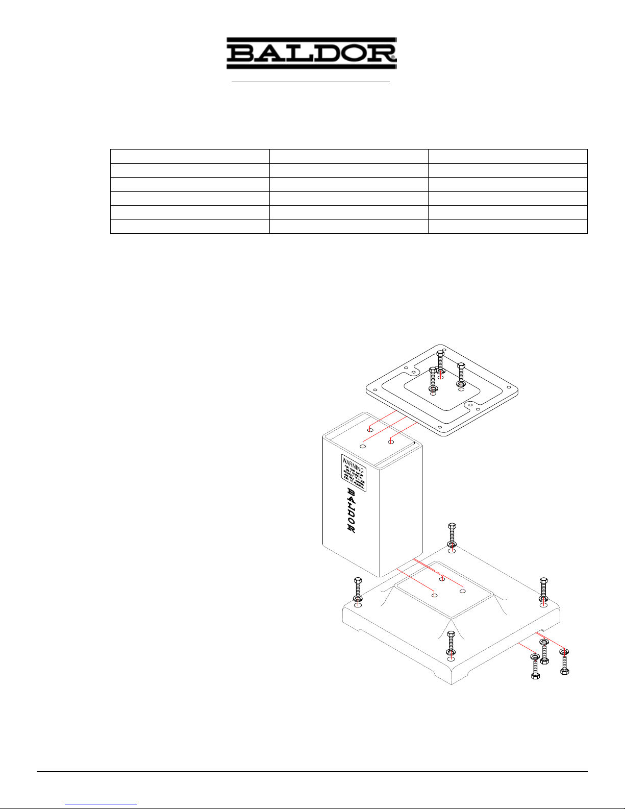
Assembly Refer to Figure 1 during assembly.
1. Remove parts from carton.
2. Place a lock washer on each screw.
3. Place pedestal in vertical position on a at, level surface
(oor) so that the pedestal is stable and the labels may be
read correctly (Figure 1).
4. Place the top plate on top of the pedestal, and align the
3 screw holes in the top plate with the 3 tapped holes in the
pedestal.
5. Secure the top plate to the pedestal using 3 screws and
lock washers supplied. Tighten the screws to
19.1 to 23.3 lb−ft using torque wrench.
6. Rotate the pedestal/top plate assembly upside down. Be
sure the assembly is stable and that it will not tip over.
7. Place the Base Plate on the pedestal, and align the 3 screw
holes in the Base Plate with the 3 tapped holes in the
pedestal.
8. Attach the Base Plate to the pedestal using 3 screws and
lock washers supplied. Tighten the screws to
19.1 to 23.3 lb−ft using torque wrench.
9. Rotate the pedestal assembly to it’s normal position so that
the Base Plate is down.
10. Secure the pedestal Base Plate to the oor (hardware not
provided) before mounting the grinder or buffer to the
pedestal.
11. Secure the grinder or buffer to the pedestal, refer to manual
for the grinder or buffer.
Figure 1 Pedestal Components
Top Plate
Pedestal
Base Plate
1MN901
Page 2

P.O. Box 2400, Fort Smith, AR 72902-2400 U.S.A., Ph: (1) 479.646.4711, Fax (1) 479.648.5792, International Fax (1) 479.648.5895
© Baldor Electric Company
MN901
Baldor Electric Company
www.baldor.com
All Rights Reserved. Printed in USA.
10/05
 Loading...