

Baldor FPX A02T, FPX A02S, FPX A015S, FP4 A02TB, FP4 A07TB Installation & Operating Manual
...Page 1

SERVO DRIVE
Servo Control
Installation & Operating Manual
Flex+Drive
2/03 MN1276
Page 2

Table of Contents
Section 1
General Information 1-1.............................................................
CE Compliance 1-1..............................................................
Limited Warranty 1-1.............................................................
Product Notice 1-2...............................................................
Safety Notice 1-2................................................................
Section 2
Product Overview 2-1...............................................................
Section 3
Receiving and Installation 3-1.......................................................
Receiving & Inspection 3-1.......................................................
Location Considerations 3-1......................................................
Mechanical Installation 3-1........................................................
Electrical Installation 3-2..........................................................
System Grounding 3-2.......................................................
Power Disconnect 3-4.......................................................
Protection Devices 3-4.......................................................
X1 Power Connections 3-5...................................................
X1 Motor Connections 3-10....................................................
M-Contactor 3-10............................................................
Motor Thermostat 3-11........................................................
X1 Dynamic Brake Resistor 3-11...............................................
X1 +24VDC Logic Supply 3-12.................................................
X3 Control Inputs & Digital I/O Connections 3-12.................................
Factory Installed Settings 3-15.................................................
Move to Buffer 1 Position 3-15.................................................
X6 RS232 / 485 Connections 3-17..............................................
X7 Simulated Encoder Output 3-20.............................................
X8 Resolver Feedback 3-21...................................................
X9 Encoder w/Hall Tracks 3-22.................................................
Section 4
Switch Setting and Start-Up 4-1......................................................
Switch AS1 Settings 4-1..........................................................
Start-Up Procedure 4-3...........................................................
Power Off Checks 4-3.......................................................
Power On Checks 4-3.......................................................
Table of Contents iMN1276
Page 3

Section 5
Operation 5-1.......................................................................
Installing Software on your PC 5-1.................................................
Minimum system requirements 5-1............................................
Installation 5-1..............................................................
Host Ccommunications Setup 5-1..................................................
UsingTheSetupWizard 5-3......................................................
Set up Software 5-5..............................................................
Motor 5-6..................................................................
Control 5-6.................................................................
Operating Mode 5-7.........................................................
Current Parameter 5-8.......................................................
Velocity Parameter 5-8.......................................................
Positioning 5-9..................................................................
Software Triggered 5-9.......................................................
Hardware Triggered 5-9......................................................
Initialize Buffers 5-9.........................................................
Home 5-10......................................................................
Limit Switches 5-10...............................................................
Drift 5-11....................................................................
Autotune 5-11...............................................................
Main Menu Choice Descriptions 5-12................................................
File 5-12....................................................................
Edit 5-12....................................................................
Setup 5-12..................................................................
Tuning 5-13.................................................................
Watch 5-13..................................................................
Functions 5-13...............................................................
Motion 5-13.................................................................
Terminal 5-13................................................................
Windows 5-13...............................................................
PLC Program 5-14................................................................
Section 6
Troubleshooting 6-1................................................................
ii Table of Contents MN1276
Page 4

Section 7
Specifications & Product Data 7-1....................................................
Identification 7-1.................................................................
Specifications 7-2...............................................................
24VDC Logic Power Input 7-4.................................................
Velocity Control 7-4..........................................................
Resolver Feedback 7-4......................................................
Simulated Encoder Output 7-4................................................
Encoder Input 7-5...........................................................
Serial Interface 7-5..........................................................
Optional Interface 7-5........................................................
Regeneration 7-5...........................................................
Dimensions 7-6.................................................................
Section 8
CE Guidelines 8-1...................................................................
CE Declaration of Conformity 8-1..................................................
EMC -- Conformity and CE -- Marking 8-1...........................................
EMC Installation Instructions 8-3.................................................
Section 9
Accessories and Options 9-1........................................................
Cables 9-1......................................................................
Connectors 9-1..................................................................
EMC AC Mains Filter 9-2.........................................................
Regeneration Resistor 9-4........................................................
CAN Bus 9-5....................................................................
Getting Started with CAN_OPEN 9-7...............................................
Identifiers and object list 9-10......................................................
Appendix A
Manual Tuning A-1..................................................................
Motor A-2.......................................................................
Control A-2.....................................................................
Operating Mode A-3.............................................................
Current Parameter A-4...........................................................
Velocity Parameter A-4...........................................................
Drift A-5........................................................................
Manual Tuning A-5...............................................................
Plotting of Move A-9.............................................................
Pulse Follower Applications A-10...................................................
Appendix B
Command Set B-1...................................................................
MN1276
Table of Contents iii
Page 5

iv Table of Contents
MN1276
Page 6

Section 1
General Information
Copyright Baldor ! 1999. All rights reserved.
This manual is copyrighted and all rights are reserved. This document may not, in
whole or in part, be copied or reproduced in any form without the prior written
consent of Baldor.
Baldor makes no representations or warranties with respect to the contents hereof
and specifically disclaims any implied warranties of fitness for any particular
purpose. The information in this document is subject to change without notice.
Baldor assumes no responsibility for any errors that may appear in this document.
Microsoft and MS--DOS are registered trademarks, and Windows is a trademark of
Microsoft Corporation.
UL and cUL are registered trademarks of Underwriters Laboratories.
CE Compliance
A custom unit may be required, contact Baldor. Compliance to Directive
89/336/EEC is the responsibility of the system integrator. A control, motor and all
system components must have proper shielding, grounding, and filtering as
described in MN1383. Please refer to MN1383 for installation techniques for CE
compliance. For additional information, refer to Sections 3 and 8 of this manual.
Limited Warranty
For a period of two (2) years from the date of original purchase, BALDOR will repair or
replace without charge controls and accessories which our examination proves to be
defective in material or workmanship. This warranty is valid if the unit has not been
tampered with by unauthorized persons, misused, abused, or improperly installed and
hasbeenusedinaccordancewiththeinstructionsand/orratingssupplied. Thiswarranty
is in lieu of any other warranty or guarantee expressed or implied. BALDOR shall not be
held responsible for any expense (including installation and removal), inconvenience, or
consequential damage, including injury to any person or property caused by items of our
manufacture or sale. (Some states do not allow exclusion or limitation of incidental or
consequentialdamages,sotheabove exclusionmaynotapply.) Inany event,BALDOR’s
total liability, under all circumstances, shall not exceed the full purchase price of the
control. Claims for purchase price refunds, repairs, or replacements must be referred to
BALDOR with all pertinent data as to the defect, the date purchased, the task performed
bythecontrol, andtheproblemencountered. Noliabilityisassumedforexpendableitems
such as fuses.
Goods may be returned only with written notification including a BALDOR Return
Authorization Number and any return shipments must be prepaid.
General Information 1-1MN1276
Page 7

Product Notice Intended use:
These drives are intended for use in stationary ground based applications in
industrial power installations according to the standards EN60204 and VDE0160.
They are designed for machine applications that require variable speed controlled
three phase brushless AC motors.
These drives are not intended for use in applications such as:
-- Home appliances
-- Medical instrumentation
-- Mobile vehicles
-- Sh i p s
-- Airplanes
Unless otherwise specified, this drive is intended for installation in a suitable
enclosure. The enclosure must protect the control from exposure to excessive or
corrosive moisture, dust and dirt or abnormal ambient temperatures. The exact
operating specifications are found in Section 7 of this manual.
The installation, connection and control of drives is a skilled operation,
disassembly or repair must not be attempted.
In the event that a control fails to operate correctly, contact the place of purchase
for return instructions.
Safety Notice: This equipment contains high voltages. Electrical shock can cause serious or fatal
injury. Only qualified personnel should attempt the start--up procedure or
troubleshoot this equipment.
This equipment may be connected to other machines that have rotating parts or
parts that are driven by this equipment. Improper use can cause serious or fatal
injury. Only qualified personnel should attempt the start--up procedure or
troubleshoot this equipment.
-- System documentation must be available at all times.
-- Keep non-qualified personnel at a safe distance from this equipment.
-- Only qualified personnel familiar with the safe installation, operation and
maintenance of this device should attempt start-up or operating
procedures.
-- Always remove power before making or removing any connections to
this control.
PRECAUTIONS: Classifications of cautionary statements.
WARNING: Indicates a potentially hazardous situation which, if not avoided,
could result in injury or death.
Caution: Indicates a potentially hazardous situation which, if not avoided,
could result in damage to property.
1-2 General Information MN1276
Page 8

PRECAUTIONS:
WARNING: Do not touch any circuit board, power device or electrical
connection before you first ensure that power has been
disconnected and there is no high voltage present from this
equipment or other equipment to which it is connected.
Electrical shock can cause serious or fatal injury.
WARNING: Be sure that you are completely familiar with the safe operation
of this equipment. This equipment may be connected to other
machines that have rotating parts or parts that are controlled by
this equipment. Improper use can cause serious or fatal injury.
WARNING: Be sure all wiring complies with the National Electrical Code and
all regional and local codes or CE Compliance. Improper wiring
may cause a hazardous condition.
WARNING: Be sure the system is properly grounded before applying power.
Do not apply AC power before you ensure that grounds are
connected. Electrical shock can cause serious or fatal injury.
WARNING: Do not remove cover for at least five (5) minutes after AC power
is disconnected to allow capacitors to discharge. Electrical
shock can cause serious or fatal injury.
WARNING: Improper operation of control may cause violent motion of the
motor shaft and driven equipment. Be certain that unexpected
motor shaft movement will not cause injury to personnel or
damage to equipment. Peak torque of several times the rated
motor torque can occur during control failure.
WARNING: Motor circuit may have high voltage present whenever AC power
is applied, even when motor is not rotating. Electrical shock can
cause serious or fatal injury.
WARNING: If a motor is driven mechanically, it may generate hazardous
voltages that are conducted to its power input terminals. The
enclosure must be grounded to prevent a possible shock hazard.
WARNING: When operating a motor with no load coupled to its shaft,
remove the shaft key to prevent injury if it were to fly out when
the shaft rotates.
WARNING: The motor shaft will rotate during the autotune procedure. Be
certain that unexpected motor shaft movement will not cause
injury to personnel or damage to equipment.
WARNING: A DB Resistor may generate enough heat to ignite combustible
materials. To avoid fire hazard, keep all combustible materials
and flammable vapors away from brake resistors.
WARNING: The user must provide an external hard-wired emergency stop
circuit to disable the control in the event of an emergency.
Caution: To prevent equipment damage, be certain that the input power has
correctly sized protective devices installed as well as a power disconnect.
Continued on next page.
MN1276
General Information 1-3
Page 9

Caution: Suitable for use on a circuit capable of delivering not more than the RMS
symmetrical short circuit amperes listed here at rated voltage.
Horsepower
RMS Symmetrical Amperes
1--50 5,000
Caution: Avoid locating control immediately above or beside heat generating
equipment, or directly below water or steam pipes.
Caution: Avoid locating control in the vicinity of corrosive substances or vapors,
metal particles and dust.
Caution: For UL installations, do not connect any resolver cable shields to the
motor frame. At a minimum, resolver signal integrity will be compromised
and damage to the control may result.
For CE installations, refer to CE guidelines stated in Sections 3 and 8 of
this manual.
Caution: Do not connect AC power to the control terminals U, V and W. Connecting
AC power to these terminals may result in damage to the control.
Caution: Baldor recommends not using “Grounded Leg Delta” transformer power
leads that may create ground loops and degrade system performance.
Instead, we recommend using a four wire Wye.
Caution: Logic signals are interruptible signals; these signals are removed when
power is removed from the drive.
Caution: Controls are intended to be connected to a permanent main power source,
not a portable power source. Suitable fusing and circuit protection devices
are required.
Caution: The safe integration of the drive into a machine system is the
responsibility of the machine designer. Be sure to comply with the local
safety requirements at the place where the machine is to be used. In
Europe this is the Machinery Directive, the ElectroMagnetic Compatibility
DirectiveandtheLowVoltageDirective.IntheUnitedStatesthisisthe
National Electrical code and local codes.
Caution: Controls must be installed inside an electrical cabinet that provides
environmental control and protection. Installation information for the drive
is provided in this manual. Motors and controlling devices that connect to
the drive should have specifications compatible to the drive.
Caution: Violent jamming (stopping) of the motor shaft during operation may
damage the motor and control.
Caution: Do not tin (solder) exposed wires. Solder contracts over time and may
cause loose connections.
Caution: Electrical components can be damaged by static electricity. Use ESD
(electro-static discharge) procedures when handling this control.
Caution: Ensure that resolver or encoder wires are properly connected. Incorrect
installation may result in improper rotation or incorrect commutation.
Caution: The holes in the top and bottom of the enclosure are for cable clamps. Be
sure to use an M4 bolt 12mm in length. Longer bolts may short circuit the
electrical components inside the control.
1-4 General Information
MN1276
Page 10

Section 2
Product Overview
Overview The Flex+Drive product is designed to serve the needs of machine designers and
manufacturers. Baldor products have both UL and CE approvals. The Flex+Drive
is a “flexible” versatile compact control for brushless servo motors. This digital
servo control can be tailored to suit many applications. It can accept 0--10VDC
input, standard "10VDC input, current loop input, electronic handwheel input or 15
preset point to point moves.
Some flexible options are CAN bus interface (for resolver feedback only), internal
or external regen, or with customer provided 24VDC to maintain logic power.
The Flex+Drive can be integrated with Baldors’ motion controllers or to any
industry standard motion controller.
Motors Baldor servo controls are compatible with many motors from Baldor and other
manufacturers. Motor parameters are provided with the PC software making the
setup easy. Baldor compatible motors include:
S BSM--A--Series motors
S BSM--B--Series motors
S BSM--F--Series motors
S BSM--N--Series motors
Refer to the Speed/Torque curves in the BR1202 catalog or contact your local
Baldor distributor or sales representative for assistance with motor sizing and
compatibility. Custom motors or motors not manufactured by Baldor may be
used. Please contact your local Baldor distributor or sales representative for
assistance.
Command Source
In the analog mode (current or velocity), the control requires a variable 0-10VDC
or "10VDC external analog signal. Suitable sources can be a PLC or motion
controller.
Positioning Mode
In the positioning mode, up to 15 preset repeatable positions (moves) may be
defined in software. These moves may either be incremental, absolute or mixed.
A specific “preset” position is selected using the switch inputs (machine inputs
1--4) and a “trigger” input activates the move. A home position could also be set if
desired.
Serial Communications Interface
A serial port allows external communication. This means that the Flex+Drive can
interface to a PC (for configuration and control) or to other user--supplied
equipment such as:
S Host computers
S PLC’s
S PC’s
S Motion controllers
The serial communication interface supports:
S RS232 and the four wire RS--485 communication standards
S Baud rate: 9600
Product Overview 2-1MN1276
Page 11

Control Inputs Opto isolated inputs are single ended, user selectable and active high or low:
Enable Machine Input 1
Quit Machine Input 2
Fault Reset Machine Input 3
Home Flag Machine Input 4
Trigger
Control Outputs
One normally closed relay contact provides a dedicated “Drive Ready” output.
Two opto isolated outputs are single ended, active low and are current sinking.
Either output can be assigned to one of the following:
In Position Machine Input 1
CW Warning Machine Input 2
CCW Warning Machine Input 3
Following Error Flag Machine Input 4
Following Error Warning Drive Over Temperature
2
t Warning
I
Simulated Encoder Output
Resolver Feedback
The resolver feedback signal is converted to PPR (pulses per revolution) by a
Resolver to Digital Converter. A position controller uses position feedback
The resolution of the simulated encoder output is software controlled with the
following available resolutions:
512 PPR, 1024 PPR, 2048 PPR or 4096 PPR
Note: For speeds above 6000 RPM, resolution is limited to 1024PPR maximum.
Encoder Feedback
When encoder feedback is used, the encoder input signal is buffered and provided
at the simulated encoder output.
2-2 Product Overview MN1276
Page 12

Section 3
Receiving and Installation
Receiving & Inspection Baldor Controls are thoroughly tested at the factory and carefully
packaged for shipment. When you receive your control, there are several things
you should do immediately.
1. Observe the condition of the shipping container and report any damage
immediately to the commercial carrier that delivered your control.
2. Remove the control from the shipping container and remove all packing
materials. The container and packing materials may be retained for
future shipment.
3. Verify that the part number of the control you received is the same as the
part number listed on your purchase order.
4. Inspect the control for external physical damage that may have been
sustained during shipment and report any damage immediately to the
commercial carrier that delivered your control.
5. If the control is to be stored for several weeks before use, be sure that it
is stored in a location that conforms to published storage humidity and
temperature specifications stated in this manual.
Location Considerations The location of the control is important. Installation should be in an area
that is protected from direct sunlight, corrosives, harmful gases or liquids, dust,
metallic particles, and vibration. Exposure to these can reduce the operating life
and degrade performance of the control.
Several other factors should be carefully evaluated when selecting a location for
installation:
1. For effective cooling and maintenance, the control should be mounted
on a smooth, non-flammable vertical surface.
2. At least 0.6 inches (15mm) top and bottom clearance must be provided
for air flow. At least 0.4 inches (10mm) clearance is required between
controls (each side).
3. Altitude derating. Up to 3300 feet (1000 meters) no derating required.
Derate the continuous and peak output current by 1.1% for each 330
feet (100 meters) above 3300 feet.
4. Temperature derating.From0#Cto40#C ambient no derating
required. Above 40#C, derate the continuous and peak output current by
2.5% per #C above 40#C. Maximum ambient is 50#C.
5. The control must be installed where the pollution degree according to
IEC664 shall not exceed 2.
Mechanical Installation
Mount the control to the mounting surface. The control must be securely fastened
to the mounting surface by the control mounting holes. The location of the
mounting holes is shown in Section 7 of this manual.
Receiving & Installation 3-1MN1276
Page 13
Electrical InstallationAll interconnection wires between the control, AC power source, motor, host
control and any operator interface stations should be in metal conduits. Use listed
closed loop connectors that are of appropriate size for wire gauge being used.
Connectors are to be installed using crimp tool specified by the manufacturer of
the connector. Only class 1 wiring should be used.
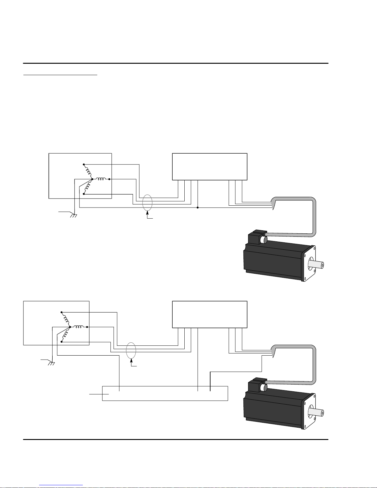
System Grounding Baldor controls are designed to be powered from standard single and three
phase lines that are electrically symmetrical with respect to ground. System
grounding is an important step in the overall installation to prevent problems. The
recommended grounding method is shown in Figure 3-1 and 3-3 for UL compliant
systems (Figure 3-2 and 3-4 for CE compliant systems).
Figure 3-1 Recommended System Grounding (3 phase) for UL
L1
AC Main
Supply
Safety
Ground
Driven Earth
Ground Rod
(Plant Ground)
Note: Use shielded cable for control signal wires. Route
control signal wires in conduit. These wires must be
kept separate from power and motor wires.
L2
L3
Earth
Four Wire
“Wye”
Route all power wires L1, L2, L3 and Earth
(Ground) together in conduit or cable.
Figure 3-2 Recommended System Grounding (3 phase) for CE
AC Main
Supply
Four Wire
“Wye”
Safety
Ground
PE
L1
L2
L3
Route all power wires
L1, L2, L3 and Earth
(Ground) together in
conduit or cable.
Control
VL1 L2 L3 U WPE
Ground per NEC and Local codes.
Control
VL1 L2 L3 U WPE
Note:
Wiring shown for clarity of
grounding method only.
Not representative of actual
terminal block location.
Note:
Wiring shown for clarity of
grounding method only.
Not representative of actual
terminal block location.
Motor
GND
All shields
Note: Use shielded cable for control signal wires. Route
control signal wires in conduit. These wires must be
kept separate from power and motor wires.
Enclosure Backplane (see Section 8)
3-2 Receiving & Installation MN1276
Page 14
AC Main
Supply
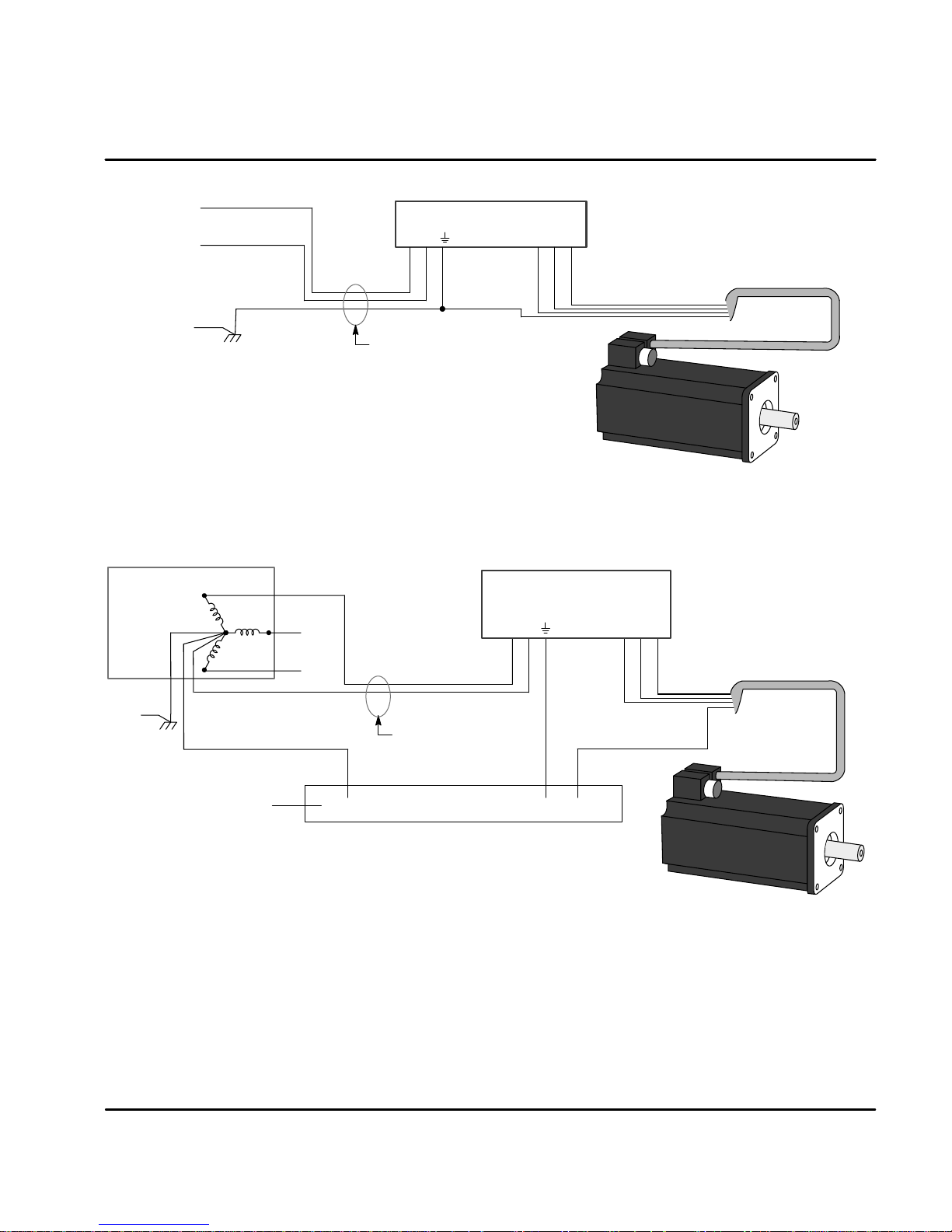
Figure 3-3 Recommended System Grounding (1 phase) for UL
L
Control
N
VLN U W
Note:
Wiring shown for clarity of grounding
method only. Not representative of
actual terminal block location.
Safety
Ground
Driven Earth
Ground Rod
(Plant Ground)
Note: Use shielded cable for control signal wires. Route
control signal wires in conduit. These wires must be
kept separate from power and motor wires.
Earth
Route all 3 wires L, N, and Earth
(Ground) together in conduit or cable.
Figure 3-4 Recommended System Grounding (1 phase) for CE
AC Main
Supply
Four Wire
“Wye”
Safety
Ground
PE
L1
L2
L3
Neutral
Route all power wires
together in conduit or
cable.
Ground per NEC and Local codes.
Control
VLN U W
Note:
Wiring shown for clarity of
grounding method only.
Not representative of actual
terminal block location.
Motor
GND
All shields
Note: Use shielded cable for control signal wires. Route
control signal wires in conduit. These wires must be
kept separate from power and motor wires.
MN1276
Enclosure Backplane (see Section 8)
Receiving & Installation 3-3
Page 15

System Grounding
Continued
Ungrounded Distribution System
With an ungrounded power distribution system it is possible to have a continuous
current path to ground through the MOV devices. To avoid equipment damage, an
isolation transformer with a grounded secondary is recommended. This provides
three phase AC power that is symmetrical with respect to ground.
Input Power Conditioning
Baldor controls are designed for direct connection to standard single and three
phase lines that are electrically symmetrical with respect to ground. Certain power
line conditions must be avoided. An AC line reactor or an isolation transformer
may be required for some power conditions.
$ If the feeder or branch circuit that provides power to the control has
permanently connected power factor correction capacitors, an input AC
line reactor or an isolation transformer must be connected between the
power factor correction capacitors and the control.
$ If the feeder or branch circuit that provides power to the control has
power factor correction capacitors that are switched on line and off line,
the capacitors must not be switched while the control is connected to the
AC power line. If the capacitors are switched on line while the control is
still connected to the AC power line, additional protection is required.
TVSS (Transient Voltage Surge Suppressor) of the proper rating must be
installed between the AC line reactor or an isolation transformer and the
AC input to the control.
Power Disconnect A power disconnect should be installed between the input power service
and the control for a fail--safe method to disconnect power. The control will remain
in a powered-up condition until all input power is removed from the control and the
internal bus voltage is depleted.
Protection Devices The control must have a suitable input power protection device installed.
Input and output wire size is based on the use of copper conductor wire r ated at
75 #C. Table 3-1 and 3-2 describes the wire size to be used for power connections
and the ratings of the protection devices. Use the recommended circuit breaker or
fuse types as follows:
Circuit Breaker: 1 phase, thermal magnetic.
Equal to GE type THQ or TEB for 115 or 230 VAC
3 phase, thermal magnetic.
Equal to GE type THQ or TEB for 230 VAC or
GE type TED for 460 VAC.
Time Delay Fuses: Buss FRN on 230 VAC or
Buss FRS on 460 VAC or equivalent.
Recommended fuse sizes are based on the following:
UL 508C suggests a fuse size of four times the continuous output
current of the control.
Dual element, time delay fuses should be used to avoid nuisance trips
due to inrush current when power is first applied.
For European installations, you may want to consider the following fast acting
fuse: Gould Shawmut Cat. No. ATMR15 for up to 15 amperes.
3-4 Receiving & Installation
MN1276
Page 16

Table 3-1 Wire Size and Protection Devices (for units with Power Supply)
g
Input
W
ireG
NominalInpu
t
CatalogNumb
W
ireG
g
Continuou
s
Catalog Number Incoming Power
Input
Fuse
Time
Delay (A)
AWG
(USA)
FP1A02SR-XXXX
FP2A02SR-XXXX
FP1A02TR-XXXX
FP2A02TR-XXXX
FP4A02TB-XXXX
FP1A05SR-XXXX
FP1A05SR-XXXX
FP1A05TR-XXXX
FP2A05TR-XXXX
FP4A05TB-XXXX
FP1A07TR-XXXX
FP2A07TR-XXXX
FP4A07TR-XXXX
FP1A10SR-XXXX
FP2A10SR-XXXX
FP1A15SR-XXXX
FP2A15SR-XXXX
FP4A15TR-XXXX
FP4A20TR-XXXX
FP4A27TR-XXXX
Nominal Input
Voltage
115V (1Ô)
230V (3Ô)
115V (1Ô)
230V (1Ô)
400/460V (3Ô)
115V (1Ô)
230V (3Ô)
115V (1Ô)
230V (1Ô)
400/460V (3Ô)
115V (1Ô)
230V (1Ô)
400/460V (3Ô)
115V (1Ô)
230V (3Ô)
115V (1Ô)
230V (3Ô)
400/460V (3Ô)
400/460V (3Ô)
400/460V (3Ô)
Continuous
Output
(RMS)
Amps
2.0A 7.5 8 14 2.5
2.5A 7 4.5 14 2.5
2.0A 7.5 8 14 2.5
2.5A 5 4.5 14 2.5
2.5A 7 4 14 2.5
5A 7.5 8 14 2.5
5A 7 8 14 2.5
5A 7.5 8 14 2.5
5A 7.5 7 14 2.5
5A 7 7.5 14 2.5
7.5A 10 10 14 2.5
7.5A 10 10 14 2.5
7.5A 15 12 14 2.5
10A 12.5 15 14 2.5
10A 15 15 14 2.5
15A 20 20 12 2.5
15A 20 25 12 2.5
15A 20 20 12 2.5
20A 30 35 10 5.26
27.5A 40 45 10 5.26
Input
Breaker
(A)
auge
mm
(Europe)
2
Table 3-2 Wire Size (for units without Power Supply)
er
Bus
Voltage
FP1A02PO-xxxx 160VDC 2.0A 14 2.5
FP2A02PO-xxxx 300VDC 2.5A 14 2.5
FP1A05PO-xxxx 160VDC 5.0A 14 2.5
FP2A05PO-xxxx 300VDC 5.0A 14 2.5
FP1A10PO-xxxx 160VDC 10.0A 12 2.5
FP2A10PO-xxxx 300VDC 10.0A 12 2.5
FP1A15PO-xxxx 160VDC 15.0A 10 2.5
FP2A15PO-xxxx 300VDC 15.0A 10 2.5
Continuous
Output
Amps
AWG
(USA)
Note: All wire sizes are based on 75#C copper wire. Higher temperature smaller gauge wire may
be used per NEC and local codes. Recommended fuses/breakers are based on 25 # C
ambient, maximum continuous control output current and no harmonic current.
X1 Power Connections
Power connections are shown in Figures 3-5 through 3-8.
MN1276
auge
mm
(Europe)
2
Receiving & Installation 3-5
Page 17
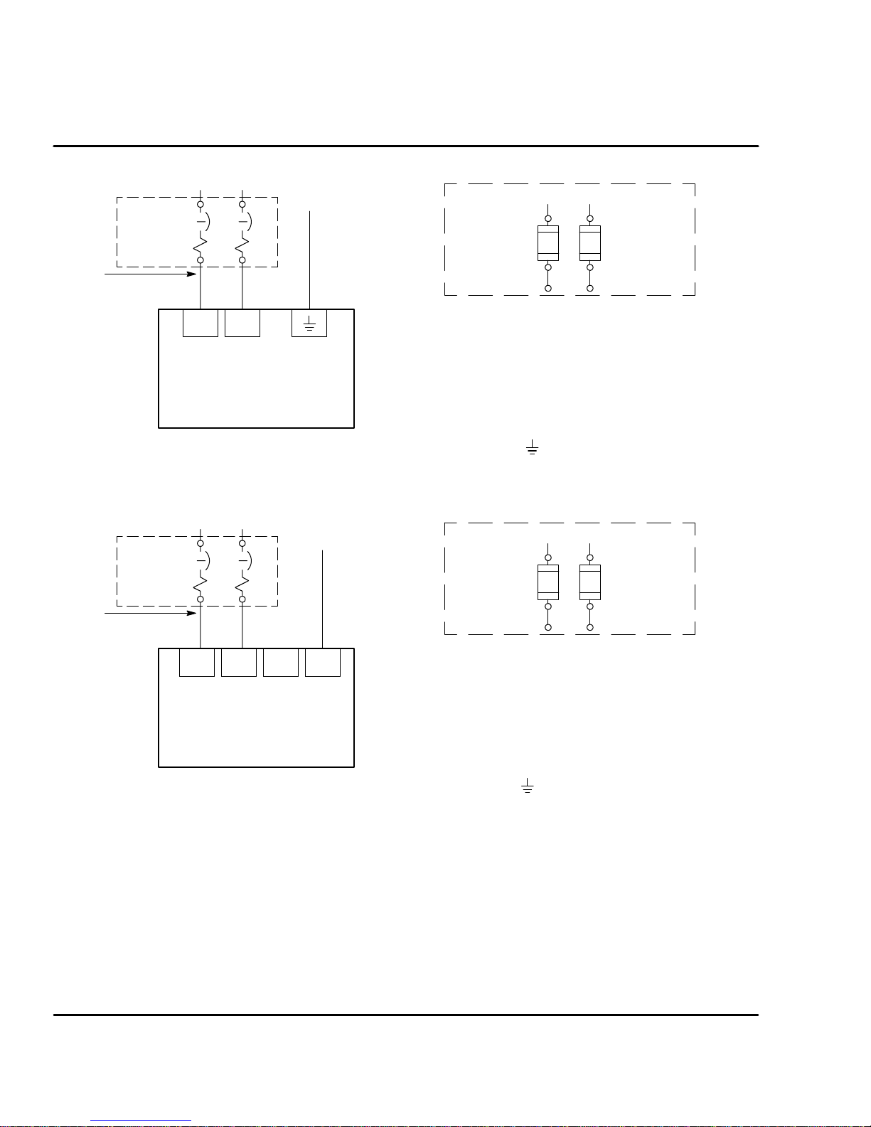
Figure 3-5 Single Phase AC Power Connections (FP1AxxT & FP2AxxT only)
L1 L2
L1 L2
Note 1
Note 2
* Circuit
Breaker
Earth
Note 3 & 4
Alternate *
Fuse
Connection
Note 1
LN
Baldor
Control
For CE Compliance, refer to Section 8 of this manual.
Figure 3-6 Single Phase AC Power Connections (FP1AxxS only)
L1 L2
Earth
Note 1
Note 2
For CE Compliance, refer to Section 8 of this manual.
* Circuit
Breaker
L1 L2 L3
Baldor
Control
Note 3 & 4
PE
* Components not provided with Control.
Notes:
1. See “Protection Devices” described in this section.
2. Metal conduit or shielded cable should be used. Connect
conduits so the use of a Reactor or RC Device does not
interrupt EMI/RFI shielding.
3. Use same gauge wire for Earth ground as is used for L and N.
(VDE (Germany) requires 10mm
Compliance, connect tothe backplane of the enclosure.
4. Reference EMC wiring in Section 8.
2
minimum). For CE
L1 L2
Alternate *
Fuse
Note 1
Connection
* Components not provided with Control.
Notes:
1. See “Protection Devices” described in this section.
2. Metal conduit or shielded cable should be used. Connect
conduits so the use of a Reactor or RC Device does not
interrupt EMI/RFI shielding.
3. Use same gauge wire for Earth ground as is used for L and N.
(VDE (Germany) requires 10mm
Compliance, connect tothe backplane of the enclosure.
4. Reference EMC wiring in Section 8.
2
minimum). For CE
Note: These Flex+Drive versions are not designed for use with 400/460VAC
connections.
3-6 Receiving & Installation
MN1276
Page 18
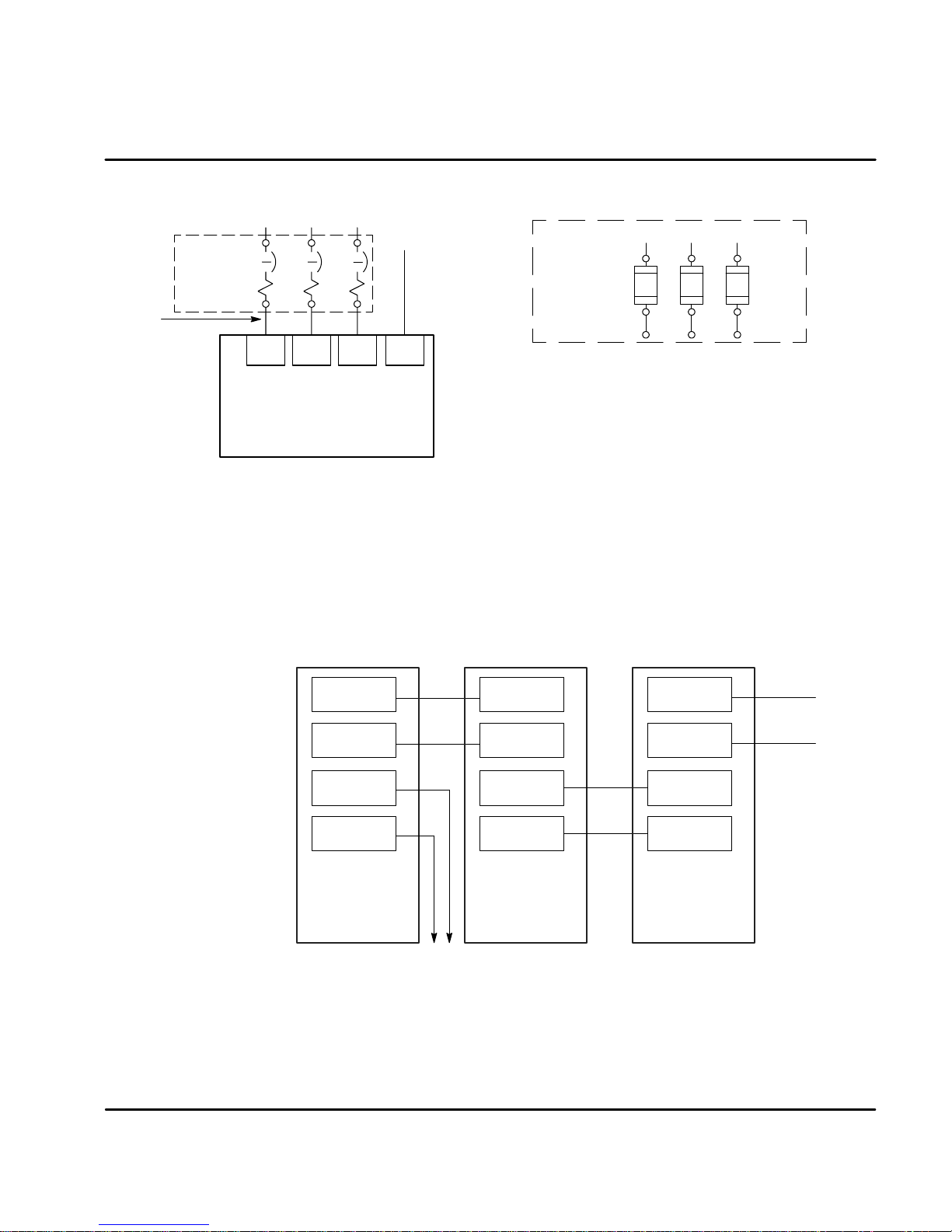
Figure 3-7 3 Phase Power Connections (FP2AxxS & FP4AxxT only)
L1 L2 L3
Earth
Note 1
Note 2
For CE Compliance, refer to Section 8 of this manual.
* Circuit
Breaker
L1 L2 L3
PE
Baldor
Control
A shared supply configuration is shown in Figure 3-8. The first drive must have an
internal power supply such as an Option “S” control.
L1 L2 L3
Note 3 & 4
Notes:
1. See Protection Device description in this section.
2. Metal conduit or shielded cable should be used. Connect
conduitsso theuse ofa Reactoror RC Devicedoes notinterrupt
EMI/RFI shielding.
3. Use the same gauge wire for Earth as used for L1, L2, L3
connections.
3. Use same gauge wire for Earth ground as is used for L and N.
(VDE (Germany) requires 10mm
compliance, connect “PE” to the backplane of the enclosure.
4. Reference EMC wiring in Section 8.
Alternate *
Fuse
Connection
A1 B1 C1
Note 1
* Components not provided with Control.
2
minimum). For CE
Figure 3-8 Shared Supply Power Connections
VCC+
VCC-
R1
R2
Baldor
Option S
Control
To
Regen
Resistor
VCC+
VCC-
VCC+
VCC-
Baldor
Option P
Control
VCC+
VCC-
VCC+
Baldor
Option P
Control
VCC-
MN1276
Receiving & Installation 3-7
Page 19
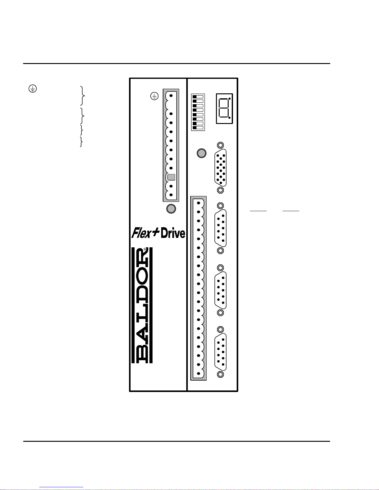
Figure 3-9 Connector Locations (Single Phase Controls)
X1 - Power Connector
Earth
LACLine
N Neutral
U Motor lead “U”
V Motor lead “V”
W Motor lead “W”
R1 Dynamic Brake
R2 Dynamic Brake
+24V Customer
0V Provided
Terminal tightening torque is
0.5 lb-in (0.6Nm)
X3 - Control Signals & Digital I/O
1CMD+
2CMD3AGND
4 Fault Relay+
5 Fault Relay-6CIV
7 CREF
8CGND
9 Enable
10 MaI3
11 MaI4
12 Quit
13 Fault Reset
14 Home Flag
15 Trigger
16 MaI1
17 MaI2
18 MaO1
19 MaO2
20 DrOK
Input Power
Motor
Dynamic Brake
(Regen Resistor)
FPxAxxxx-xxx3
only ¡
NC
L
N
U
V
W
R1
R2
+24V
0V
DB On
X1
AS1
Off/On
Ready
Monitor
1
2
3
4
5
6
7
8
The holes in the top and
bottom of the enclosure
are for cable clamps. Be
sure to use an M4 bolt
12mm in length. Longer
bolts may short circuit the
electrical components
inside the control.
X9 - Encoder Feedback Option
(only --Exxx versions)
1 CHA+ 9 HALL3+
2 CHB+ 10 HALL2+
3 CHC+ 11 +5VDC
4 HALL1+ 12 N.C.
5 HALL1-- 13 DGND
6 CHA-- 14 HALL3--
Encoder In X9RS232 / 485 X6Encoder Out X7Resolver In X8
7 CHB-- 15 HALL2-8 CHC--
X6 - RS232 / 485
RS232
1 Reserved 1 TX-
Data 2 TX+
2R
x
3T
Data 3 RX+
x
4DTR 4RX5 DGND 5 DGND
6DSR 6RTS7RTS 7RTS+
8CTS 8CTS+
9+5V 9CTS-
X7 - Simulated Encoder Output
1 CHA 6 CHA-2 CHB 7 CHB-3 CHC 8 CHC-4 Reserved 9 Reserved
5DGND
X8 - Resolver Input
1REF 6REF-2COS 7COS-3SIN 8SIN-4 Reserved 9 Reserved
5AGND
RS485
Important:
¡
FPxAxxxx-xxx3 only.
A separate 24VDC supply to the “Logic Power” input is required for
operation. An FPxAxxxx-xxx3 control will not operate without 24VDC
on this input.
3-8 Receiving & Installation
X3
Note: Reserved means no
connection is required and
no connection should be
made to this terminal. It is
reserved for future use.
MN1276
Page 20

Figure 3-10 Connector Locations (Three Phase Controls)
X1 - Power Connector
PE Earth
L1 Phase 1 Input
L2 Phase 2 Input
L3 Phase 3 Input
U Motor lead “U”
V Motor lead “V”
W Motor lead “W”
R1 Dynamic Brake
R2 Dynamic Brake
+24V Customer
0V Provided
Terminal tightening torque is
0.5 lb-in (0.6Nm)
X3 - Control Signals & Digital I/O
1CMD+
2CMD3AGND
4 Fault Relay+
5 Fault Relay-6CIV
7 CREF
8CGND
9 Enable
10 MaI3
11 MaI4
12 Quit
13 Fault Reset
14 Home Flag
15 Trigger
16 MaI1
17 MaI2
18 MaO1
19 MaO2
20 DrOK
Input Power
Motor
Dynamic Brake
(Regen Resistor)
FPxAxxxx-xxx3
only ¡
The holes in the top and bottom of the
enclosure are for cable clamps. Be sure
to use an M4 bolt 12mm in length.
Longer bolts may short circuit the
electrical components inside the control.
X9 - Encoder Feedback Option
(only --Exxx versions)
1 CHA+ 9 HALL3+
2 CHB+ 10 HALL2+
3 CHC+ 11 +5VDC
4 HALL1+ 12 N.C.
5 HALL1-- 13 DGND
6 CHA-- 14 HALL3-7 CHB-- 15 HALL2-8 CHC--
X6 - RS232 / 485
RS232
1 Reserved 1 TX-
Data 2 TX+
2R
x
Data 3 RX+
3T
x
4DTR 4RX5 DGND 5 DGND
6DSR 6RTS7RTS 7RTS+
8 CTS 8 CTS+
9 +5V 9 CTS-
X7 - Simulated Encoder Output
1 CHA 6 CHA-2 CHB 7 CHB-3 CHC 8 CHC-4 Reserved 9 Reserved
5DGND
X8 - Resolver Input
1 REF 6 REF-2 COS 7 COS-3SIN 8SIN-4 Reserved 9 Reserved
5AGND
RS485
¡ Important:
FPxAxxxx-xxx3 only.
A separate 24VDC supply to the “Logic Power” input is required for
operation. An FPxAxxxx-xxx3 control will not operate without 24VDC on this input.
MN1276
Note: Reserved means no connection is required
and no connection should be made to this
terminal. It is reserved for future use.
Receiving & Installation 3-9
Page 21
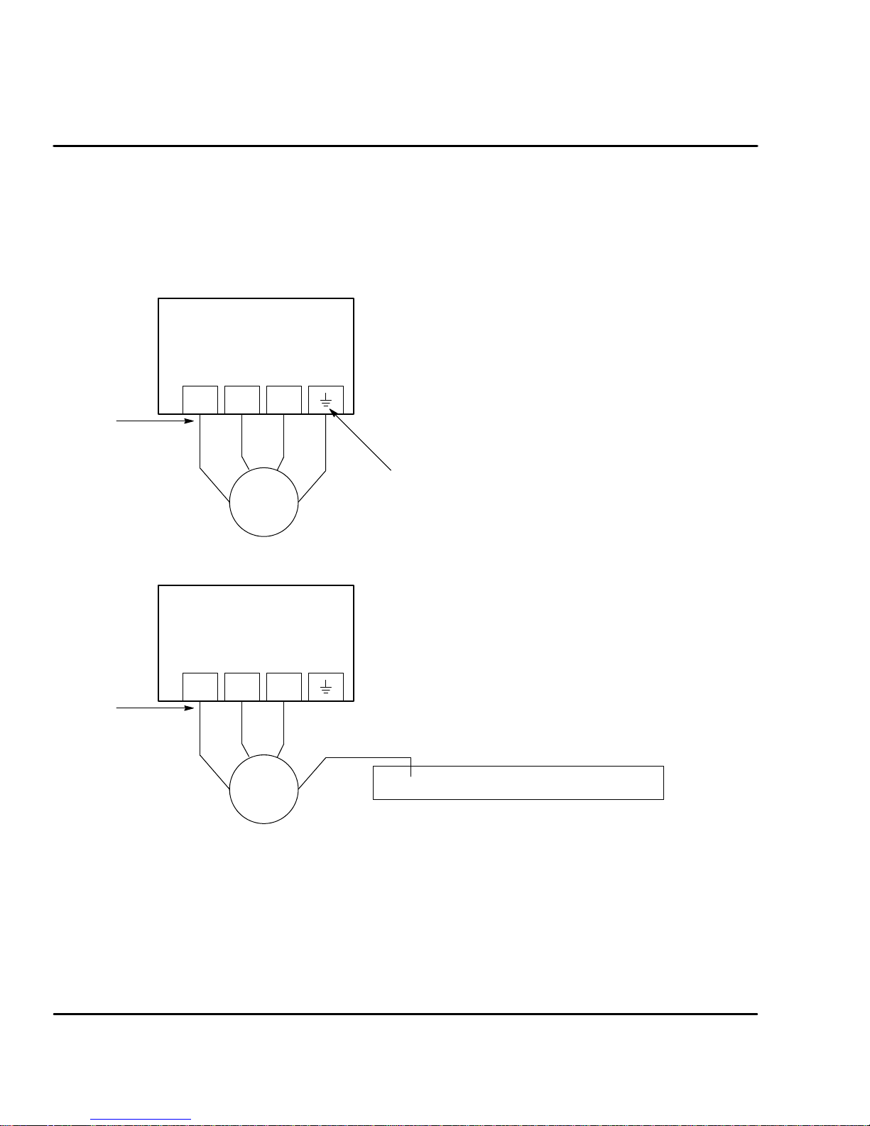
X1 Motor Connections Motor connections are shown in Figure 3-11 and Figure 3-12.
It is important to connect the motor leads U, V and W correctly at the X1 connector
of the control. Incorrect wiring can cause erratic operation including moves at
peak force until the overcurrent limit trips. This will result in a display of “7” and a
“6” on the monitor. If erratic movement of the motor occurs, turn off power
immediately and check the connections of the motor, resolver or hall sensors and
encoder.
Figure 3-11 Motor Connections for UL
Notes:
Baldor
Control
UVW
Note 1
1. Metal conduit or shielded cable should be used. Connect
conduits so the use of Load Reactor* or RC Device* does not
interrupt EMI/RFI shielding.
2. Use same gauge wire for Earth ground as is used for L and N.
(VDE (Germany) requires 10mm
3. Reference EMC wiring in Section 8.
4. Motor and resolver are phase sensitive. Connect only as
instructed.
2
minimum, 6AWG).
Note 1
* AC Servo Motor
* AC Servo Motor
Note: For CE compliant installations, connect unused leads within the motor cable
VW
U
G
Note 2
* Optional components not provided with control.
Figure 3-12 Motor Connections for CE
Notes:
Baldor
Control
UVW
VW
U
Note 2
G
to “PE” on both ends of the cable.
1. Metal conduit or shielded cable should be used. Connect
2. Use same gauge wire for Earth ground as is used for L and N.
3. Reference EMC wiring in Section 8.
4. Motor and encoder are phase sensitive. Connect only as
For three phase controls, this is labeled “PE”.
conduits so the use of Load Reactor* or RC Device* does not
interrupt EMI/RFI shielding.
(VDE (Germany) requires 10mm
compliance, connect motor ground to the backplane of the
enclosure.
instructed.
Enclosure Backplane (see Section 8)
2
minimum, 6AWG). For CE
* Optional components not provided with control.
M-Contactor If required by local codes or for safety reasons, an M-Contactor (motor circuit
contactor) may be installed. However, incorrect installation or failure of the
M-contactor or wiring may damage the control. If an M-Contactor is installed, the
control must be disabled for at least 20msec before the M-Contactor is opened or
the control may be damaged. M-Contactor connections are shown in Figure 3-13.
3-10 Receiving & Installation
MN1276
Page 22
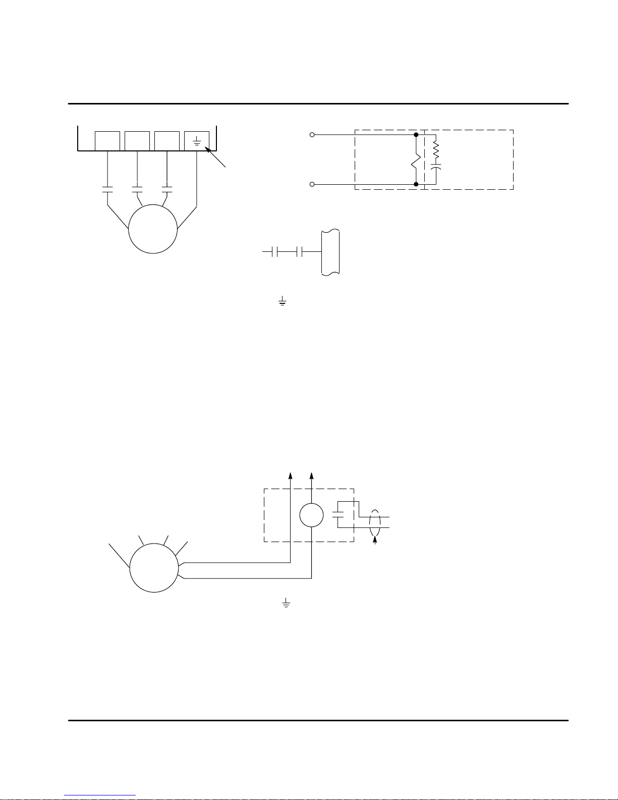
Figure 3-13 Optional M-Contactor Connections
UVW
To Power Source
(Rated Coil Voltage)
Note 1
Note 2
For three phase
controls, this is
labeled “PE”.
M Enable
* Optional components not provided with control.
*
X3
9
*
MMM
VW
U
G
* Motor
M=Contacts of optional M-Contactor
Notes:
1. Use same gauge wire for Earth ground as is used for L and N. (VDE (Germany) requires 10mm
2. For UL installations, connect motor ground to of the control as shown.
For CE installations, connect motor ground to the enclosure backplane (see Figure 3-12).
* M-Contactor
Note: Close “Enable”
after “M” contact closure.
* RC Device
Electrocube
RG1781-3
2
minimum, 6AWG).
Motor Thermostat A relay contact can be used to isolate the motor thermostat leads for use
with other devices, shown in Figure 3-14. The thermostat or overload relay should
be a dry contact type with no power available from the contact. The optional relay
(CR1) shown provides the isolation required and the N.O. contact is open when
power is applied to the relay and the motor is cold. If the motor thermostat is
tripped, CR1 is de-energized and the N.O. contact closes.
Connect the External Trip Input wires (N.O. relay contact) to a PLC or other
device. Note that a machine input may be used and the PLC software of the
Flex+Drive can define the thermal protection. Do not place these wires in the
same conduit as the motor power leads.
Figure 3-14 Motor Temperature Relay
Customer Provided
Source Voltage
Note: Add appropriately rated protective
device for AC relay (snubber)
or DC relay (diode).
W
V
U
Note:
1. For UL installations, connect motor ground to of the control as shown.
For CE installations, connect motor ground to the enclosure backplane (see Figure 3-12).
* Motor
Note 1
G
Motor Thermostat Leads
X1 Dynamic Brake Resistor An external DB (dynamic brake or regen resistor) resistor may be
required to dissipate excess power from the DC bus during motor deceleration
operations. Some controls have an internal resistor. For selection of the DB
resistor, refer to the specifications located in Section 7 and the regeneration
resistor specifications in Section 9 of this manual. DB hardware is connected at
R1 and R2 terminals of the X1 connector, Figure 3-9 and 3-10.
MN1276
*
CR1
Do not run these wires in same conduit
as motor leads or AC power wiring.
Optional, customer supplied.
*
External Trip
Receiving & Installation 3-11
Page 23
X1 +24VDC Logic Supply For FPxAxxxx-xxx3 only. A separate 24VDC supply to the “Logic
X
A
Power” input is required for operation. An external 24 VDC power source must be
used. If bus power is lost, the logic circuits are still active if the 24VDC is present.
This is important to maintain position reference, for example. If the control was
not ordered with this option, do not connect any voltage to these pins.
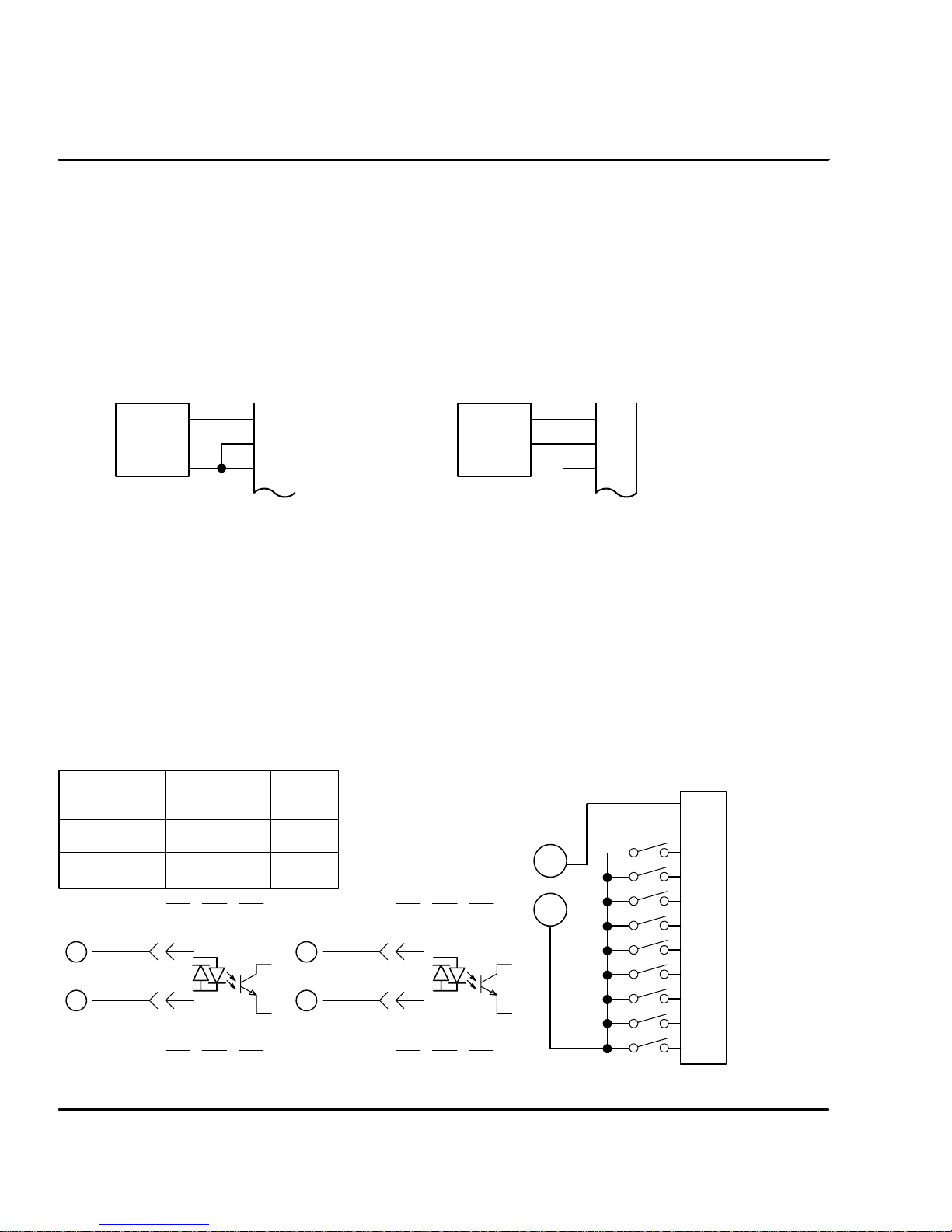
X3 Control Inputs & Digital I/O Connections
Control Inputs X3 pins 1 and 2 allows connection of an external analog command input. This
input can accept a 0-10VDC or "10VDC signal and can be wired as a single
ended or differential input, shown in Figure 3-15.
Figure 3-15 Control Input Wiring
Single Ended Connection Differential Connection
X3
X3
CMD+
Signal
Source
1
CMD-
2
AGND
3
Signal
Source
X3 Digital Inputs - Opto Isolated Inputs (uses CREF, X3-7)
Active High (Sourcing) - If pin X3-7 is grounded, an input is active when it is
at +24VDC (+12VDC to +30VDC).
Active Low (Sinking) - If pin X3-7 is at +24VDC (+12VDC to +30VDC), an
input is active when it is grounded.
Logic input connections are made at terminal strip X3. Input connections can be
wired as active High or active Low as shown in Figure 3-16. X3 pin 7 is the
Control Reference point (CREF) for the Opto Isolated Input signals.
Note: An internal 24VDC power supply connection is not available from the control
to power the Opto Input circuits. A customer provided external power
source must be used as indicated in Figure 3-16.
Figure 3-16 Active HIGH /LOW Relationship
Active Low
(Sink)
+24VDC
GND
+24VDC
B
GND
A
Source
Active High
(Source)
GND
+24VDC
20mA 20mA
9-17
7
Typical
Control
Input
A
B
B
A
Note:
GND
+24VDC
Sink
ll Opto inputs are referenced to
CREF, X3-7.
9-17
7
Typical
Control
Input
A
B
CMD+
1
CMD-
2
AGND
3
3
CREF
7
CGND
8
ENABLE
9
MAI3
10
MAI4
11
QUIT
12
FAULT RESET
13
HOME FLAG
14
TRIGGER
15
16
MAI1
MAI2
17
3-12 Receiving & Installation
MN1276
Page 24

X3 Digital Inputs Continued
Table 3-3 Opto Input Signal Conditions
Pin
Number
X3-9 Enable Drive enabled. Drive disabled.
X3-10 MaI3 Machine Input 3 = Logical 1 Machine Input 3 = Logical 0
X3-11 MaI4 Machine Input 4 = Logical 1 Machine Input 4 = Logical 0
X3-12 Quit Stop positioning mode operation Positioning mode is operating
X3-13 Fault Reset Fault Reset is active (reset control). Fault Reset is not active.
X3-14 Home Flag Home flag = closing (rising) edge Home flag = opening (falling) edge
X3-15 Trigger Trigger = closing (rising) edge Trigger = opening (trailing) edge
X3-16 MaI1 Machine Input 1 = Logical 1 Machine Input 1 = Logical 0
X3-17 MaI2 Machine Input 2 = Logical 1 Machine Input 2 = Logical 0
Signal
Name
Switch = Closed (active) Switch = Open (not active)
Signal Name Opto Input Signal Definition
Enable CLOSED allows normal operation.
OPEN disables the control and motor coasts to a stop.
Quit CLOSED cancels any move in progress and the motor will decelerate (at
parameter MOT.ACC) to rest. This input is edge triggered.
OPEN allows position mode operation.
Fault Reset CLOSED allows the control to be cleared or “Reset” for any of the following four
fault conditions (provided that the cause of the fault has been removed):
$ Overvoltage $ Electronic Fusing
$ Undervoltage $ Resolver Fault
OPEN allows normal operation.
Home Flag Edge triggered input that is used to sense the “Home Position”.
Trigger Rising edge triggered input that initiates a “point-to-point move”. The move is
defined by the machine inputs MaI1-4.
MaI1,2,3,& 4 Four machine inputs are provided. These may be used with the internal PLC
software program. The internal PLC software can cause an event to occur based
on the presence of these inputs.
However, more often these inputs are used to define up to 15 preset positions or
point to point moves. The 16th move is always home. With this method, it is not
possible to use hardware limits (CW and CCW). Therefore, software limits must
be used. Software limits are only active after a homing routine has completed.
Note: Hardware limit switches may be wired in series with the “Enable” input
X3--9. Then if a limit is reached, the control will be disabled.
MN1276
Receiving & Installation 3-13
Page 25
X3 Digital Inputs Continued
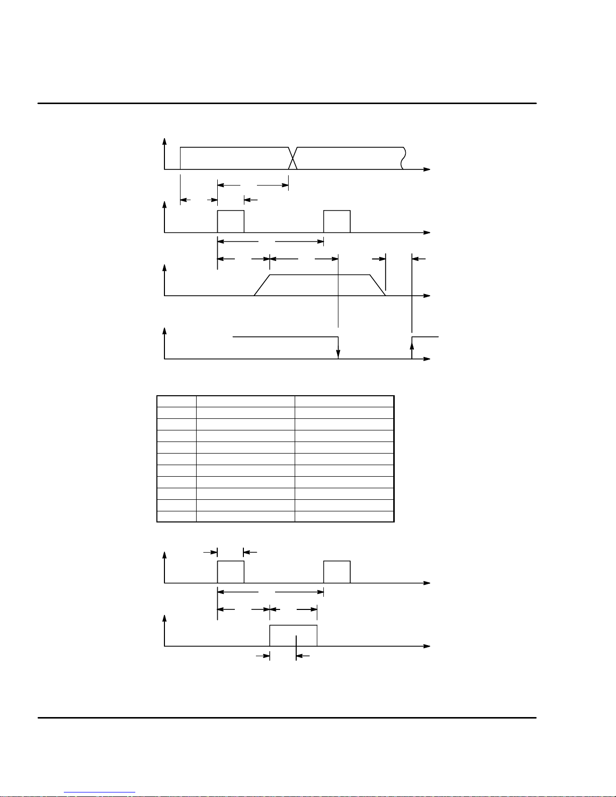
Figure 3-17 Positioning Mode Timing Diagram
MaI1-4
SeeTable3-4.
Trajectory
Motion Ready =
Motion in Process
Table 3-4 Process Duration for Resolver and Encoder Feedback
Trigger
T3
T2
T1
T4
T5 T6
Time Resolver Encoder
T1 %1ms &2ms
T2
T3 &28ms &14ms
T4 &28ms &14ms
T5 %10ms %14ms
T6 %10ms %14ms
T7 %10ms %14ms
T8 &28ms &100ms
T9
T10
&1.2ms
&1.2ms
&1.2ms
&1ms
&2ms
&2ms
Time
Time
T7
Time
Time
Figure 3-18 Homing Process Timing Diagram
Trigger
Home Flag
SeeTable3-4.
3-14 Receiving & Installation
T2
T8 T9
T4
T10
Time
Time
Recognition Time (T10)
MN1276
Page 26

Factory Installed Settings Absolute moves
A
Buffe
r
Positi
Speed
Acceleratio
n
15 predefined absolute moves have been programmed at the factory. These
moves are defined in Table 3-5.
Table 3-5 Machine Inputs and Position Move Definitions
Buffer
(Move Number)
0(Home) OFF OFF OFF OFF 0 100 40
1 OFF OFF ON OFF 100000 2000 300
2 OFF OFF OFF ON 200000 2000 300
3 OFF OFF ON ON 300000 2000 300
4 OFF ON OFF OFF 400000 2000 300
5 OFF ON ON OFF 500000 2000 300
6 OFF ON OFF ON 600000 2000 300
7 OFF ON ON ON 700000 2000 300
8 ON OFF OFF OFF 800000 2000 300
9 ON OFF ON OFF 900000 2000 300
10 ON OFF OFF ON 1000000 2000 300
11 ON OFF ON ON 1100000 2000 300
12 ON ON OFF OFF 1200000 2000 300
13 ON ON ON OFF 1300000 2000 300
14 ON ON OFF ON 1400000 2000 300
15 ON ON ON ON 1500000 2000 300
MAI4 MAI3 MAI1 MAI2
Note: The machine Inputs of Table 3-5 are “OFF” when the switch is open.
Machine Inputs
on
Speed
(RPM)
Therefore, when MAI1 -- 4 are open, move number 0 (Home) is selected.
Move to Buffer 1 Position (Absolute move to position 100000).
Note:Tostopa movebeforeithascompleted,disablethedrive (Enableinput= Open)
orResetthe drive (Reset input = closed then open) or Quit (Quit input=closed
then open).
1. Open MAI1 -- 4 inputs (position 0 select).
2. Enable the drive.
3. Close MAI1 input.
4. Close the Trigger input. Motor immediately moves to position 100000.
5. Open the Trigger input.
cceleration
(RPM / ms)
This completes an absolute move to buffer 1 position. Use switches MAI1 -- 4 to
select other move numbers and use the Trigger switch to begin each move.
Note: If the motor is already at buffer 1 position, commanding another absolute
move to the same position will not cause the motor shaft to rotate.
Therefore, command a move to a different absolute position before
commanding another move to buffer 1 position.
MN1276
Receiving & Installation 3-15
Page 27
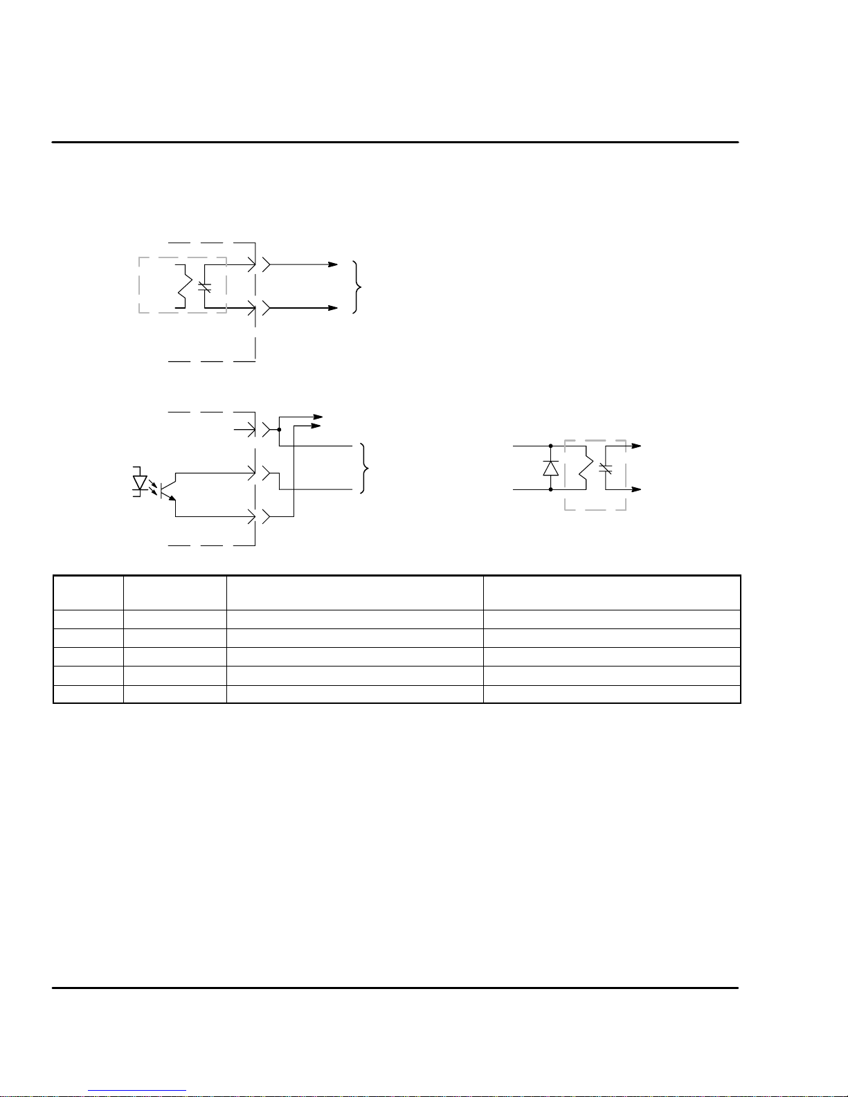
X3 Digital Outputs - Opto Isolated Outputs
The control outputs are located on the X3 connector. A customer provided,
external power supply must be used if digital outputs are to be used. The opto
outputs provide status information and are not required for operation, Table 3-6.
Figure 3-19 Fault Relay Connections
Relay
Contact is closed when power is on
and no faults are present.
Control
4
5
Customer Provided Interface Circuit
Customer provided external power source: and Non-Inductive Load
110VAC @ 0.3A maximum or
24VDC @ 0.8A maximum
Figure 3-20 Opto Output Connections
+
Typical
35mA
Maximum
CIV
18, 19, 20
CGND
Control
6
8
Customer Provided Interface Circuit
(+12VDC to +30VDC)
Output Signal
OR
Relay
Table 3-6 Opto Output Signal Conditions
Pin
Number
X3-4 Fault + Drive OK - no faults detected Fault is detected
X3-5 Fault - Drive OK - no faults detected Fault is detected
X3-18 MAO1 Machine Output 1 = Logical 1 Machine Output 1 = Logical 0
X3-19 MAO2 Machine Output 2 = Logical 1 Machine Output 2 = Logical 0
X3-20 DrOK Drive OK - no faults detected Fault is detected
Signal
Name
Switch = Closed (active) Switch = Open (not active)
Fault Relay A normally closed relay contact that opens if a fault occurs. The contact is rated:
24VDC @ 0.8A maximum or 110VAC @ 0.3A maximum.
MaO1 & 2 Two machine outputs are provided. Either output can be set to one of the
following conditions: CW Warning, CCW Warning, In Position, Error Flag,
Following Error Warning, MAI1-2, Drive Overtemperature or I
Each output is rated 30VDC @ 35mA maximum.
DrOK This output is active when the control is ready for operation.
This output is rated 30VDC @ 35mA maximum.
3-16 Receiving & Installation
2
T Warning.
MN1276
Page 28
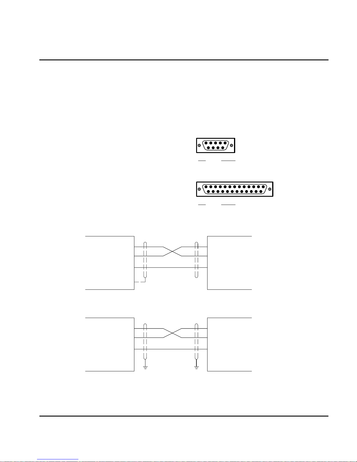
X6 RS232 / 485 Connections
RS232
A null modem cable (also called a modem eliminator cable) must be used to
connect the control and the computer COM port. This will ensure that the transmit
and receive lines are properly connected. Either a 9 pin or a 25 pin connector
can be used at the computer, Figure 3-21. Maximum recommended length for
RS232 cable is 3 ft. (1 meter).
Figure 3-21 9 & 25 Pin RS-232 Cable Connections for UL Installations
9 Pin Connector
RXD
TXD
GND
Signal
25 Pin Connector
Signal
Computer
COM
Port
(DTE)
Control
(DCE)
X6
RXD
TXD
GND
Chassis
Pin
2RXD
3TXD
5GND
Pin
2RXD
3TXD
7GND
Null Modem Cable Connections
Figure 3-22 9 & 25 Pin RS-232 Cable Connections for CE Installations
Null Modem Cable Connections
X6
Control
(DCE)
Note: For CE installations, connect the overall shield at each end of the cable to PE. The
voltage potential between the PE points at each end of the cable must be Zero Volts.
MN1276
RXD
TXD
GND
PE PE
RXD
TXD
GND
Computer
COM
Port
(DTE)
Receiving & Installation 3-17
Page 29
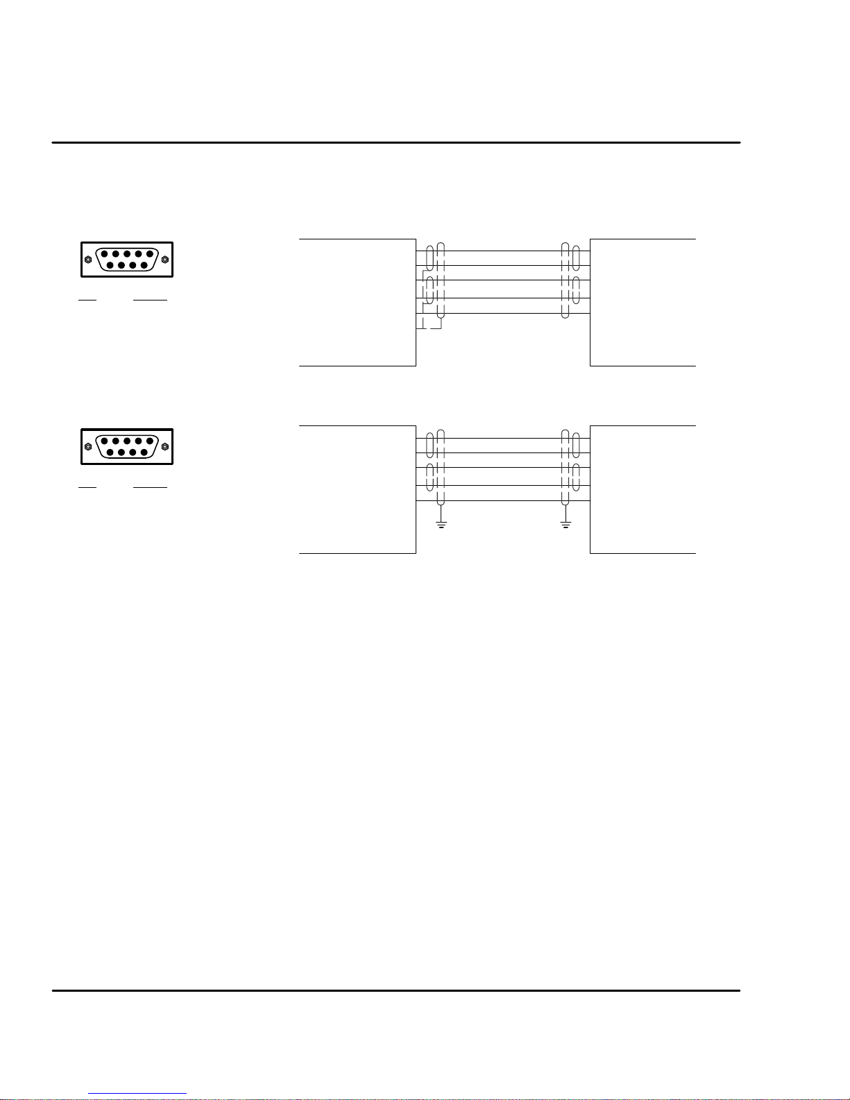
RS485
Standard RS485 connections are shown in Figure 3-24. Maximum cable length is
3280 ft (1000M).
Figure 3-23 9 Pin RS-485 Cable Connections For UL Installations
9 Pin Connector
Pin
1TX2TX+
3RX+
4RX5DGND
Signal
Control
(DCE)
X6
RX+
RX-TX+
TXDGND
Chassis
TX+
TX-RX+
RXDGND
Computer
COM
Port
(DTE)
Figure 3-24 9 Pin RS-485 Cable Connections For CE Installations
9 Pin Connector
Pin
1TX2TX+
3RX+
4RX5DGND
Signal
Note: For CE installations, connect the overall shield at each end of the cable to PE. The
voltage potential between the PE points at each end of the cable must be Zero Volts.
RS485 Multi-Drop Connections
What does termination or a termination resistor do?
Termination resistance is used to match the impedance of the load to the
impedance of the transmission line (cable) being used. Unmatched impedance
causes the transmitted signal to not be fully absorbed by the load. This causes a
portion of the signal to be reflected back into the transmission line (noise). If the
Source impedance, Transmission Line impedance, and Load impedance are all
equal, these reflections (noise) are eliminated.
Termination does increase load current and sometimes changes the bias
requirements and increases the complexity of the system.
What is a termination resistor?
A resistor is added in parallel with the receiver input to match the impedance of the
cable being used. Typically, the resistor value that is used is 100 ohm or 120 ohm.
Resistors with 90 ohms or less should never be used.
Where are these resistors placed?
Terminators or Termination resistors are placed in parallel with the receiver at both
ends of a transmission line. This means that you should never have more than
two terminators in the system (unless repeaters are being used).
How many resistors should my system have?
Terminators or Termination resistors are placed in parallel with the receiver at both
ends of a transmission line. This means that you should never have more than
two terminators in the system (unless repeaters are being used).
Control
(DCE)
X6
RX+
RX-TX+
TXDGND
Chassis
PE PE
TX+
TX-RX+
RXDGND
Computer
COM
Port
(DTE)
3-18 Receiving & Installation
MN1276
Page 30
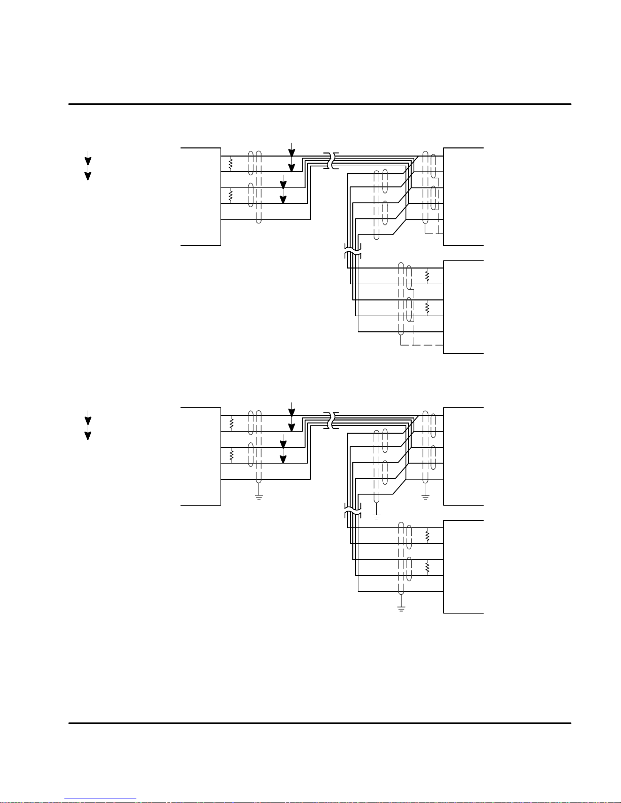
Figure 3-25 RS485 4 Wire Multi-Drop for UL Installations
Host
P
=TwistedPair
Computer
RX+
RX-TX+
TX-
DGND
GND
*
T
R
*
T
R
P
P
Use twisted pair shielded cable
with an overall shield.
* Terminating resistor TRis 120 W typical value.
Only the PC and last control are terminated.
Figure 3-26 RS485 4 Wire Multi-Drop for CE Installations
Host
Computer
P
=TwistedPair
RX+
RX-TX+
TX-
DGND
GND
Use twisted pair shielded cable
with an overall shield.
* Terminating resistor TRis 120 W typical value.
Only the PC and last control are terminated.
Note: For CE installations, connect the overall shield at each end of the cable to PE. The
voltage potential between the PE points at each end of the cable must be Zero Volts.
*
T
R
*
T
R
P
P
PE
Shields
PE
PE
Shields
PE
X6
TX+
TX-RX+
RX-
DGND
GND
X6
T
R
*
TX+
TX--
T
R
*
RX+
RX-
DGND
GND
X6
TX+
TX-RX+
RX-
DGND
GND
X6
T
R
*
TX+
TX--
T
R
*
RX+
RX-
DGND
GND
See Section 4 of this manual for the description of switch “AS1-1 to AS1-4” for
address settings for multi-drop applications.
MN1276
Receiving & Installation 3-19
Page 31

X7 Simulated Encoder Output
The control provides a simulated encoder output at connector X7. This output
may be used by external hardware to monitor the encoder signals. It is
recommended that this output only drive one circuit load (RS422 interface -28LS31 device). Refer to Table 3-7. The simulated Encoder Output is set by
software control in “General Motor & Control”.
Table 3-7 Simulated Encoder Output at X7 Connector
X7 Pin Signal Name
1 A+
2 B+
3 C+
4 Reserved
5 DGND
6 A-7 B-8 C-9 Reserved
Shell * Chassis (Cable Shield)
* For UL Installations ONLY. For CE Installations, connect the outer shield on
each end of the cable to the enclosure backplane “PE”.
3-20 Receiving & Installation
MN1276
Page 32

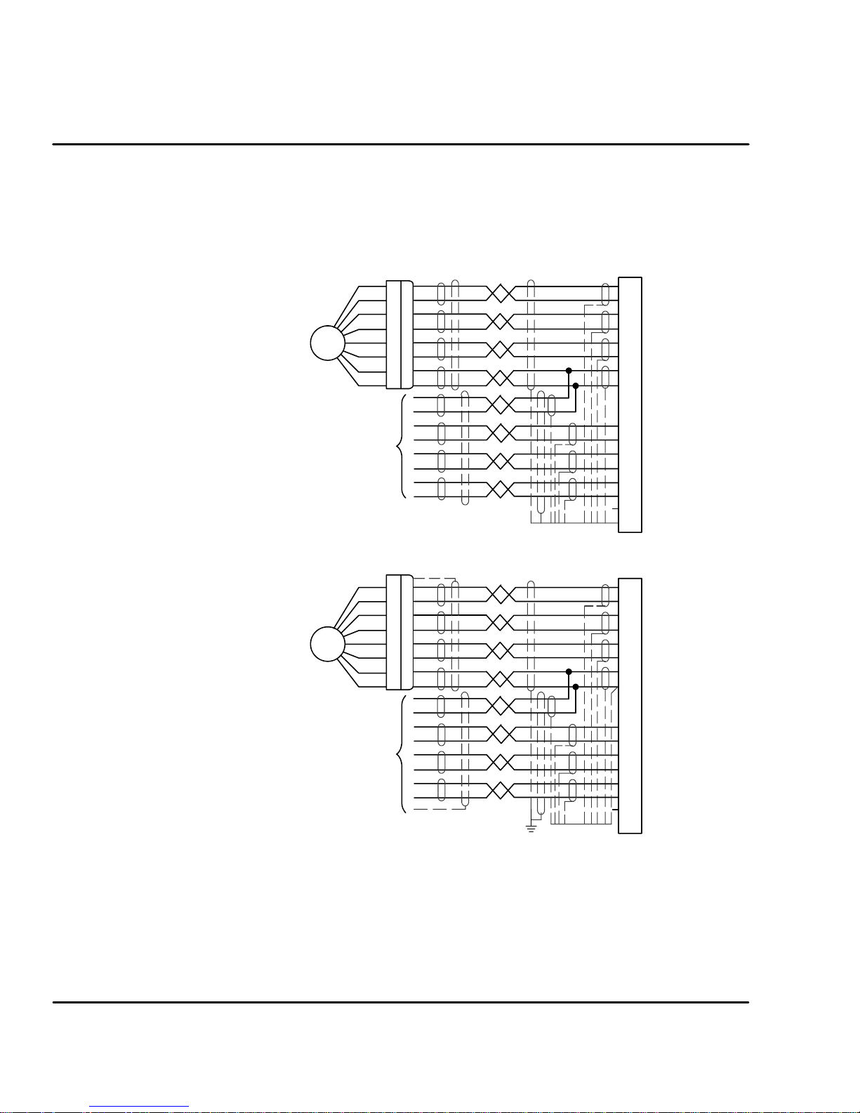
X8 Resolver Feedback The resolver connections are the standard feedback on Flex+ drives and
connections are made at the X8 connector as shown in Figure 3-27. The resolver
2
cable must be shielded twisted pair #22 AWG (0.34mm
) wire minimum. The
cable must also have an overall shield. Maximum wire-to-wire or wire-to-shield
capacitance is 50pf per foot.
Resolver wiring must be separated from power wiring. Separate parallel runs of
resolver and power cables by at least 3'. Cross power wires at right angles only.
Insulate or tape ungrounded end of shields to prevent contact with other
conductors or ground.
Note: Motor and resolver are phase sensitive. Connect only as instructed.
Figure 3-27 Resolver Cable Connections for UL Installations
R2
R1
P
=TwistedPair
S2
P
S4
P
S1S3
P
Shields
X8
3SIN+
8SIN2COS+
7COS1REF+
6 REF- (Common)
Shell (Chassis)
Figure 3-28 Resolver Cable Connections for CE Installations
R2
R1
P
=TwistedPair
S2
P
S4
P
S1S3
P
Connect overall shield
to connector backshells
X8
3SIN+
8SIN2COS+
7COS1REF+
6 REF- (Common)
5AGND
Connect internal
shields to AGND
MN1276
Receiving & Installation 3-21
Page 33
X9 Encoder w/Hall Tracks Optional (Option E)
Twisted pair shielded wire with an overall shield should be used. Figure 3-29
shows the electrical connections between the encoder and the encoder connector.
Figure 3-29 Encoder with Hall Tracks Connections for UL Installations
Encoder
Hall
Feedback
Figure 3-30 Encoder with Hall Tracks Connections for CE Installations
Encoder
X9
A+
1
A--
6
B
2
B+
7
C+
3
C--
8
+5V
11
DGND
13
4
Hall 1+
5
Hall 1--
9
Hall 3+
14
Hall 3-Hall2+
10
Hall 2--
15
12 Not Used
Shell (Chassis)
X9
1
A+
6
A--
2
B
7
B+
C+
3
C--
8
11
+5V
DGND
13
3-22 Receiving & Installation
Hall
Feedback
Hall 1+
4
Hall 1--
5
Hall 3+
9
Hall 3--
14
Hall2+
10
Hall 2--
15
Not Used
12
Shell (Chassis)
MN1276
Page 34

Section 4
Switch Setting and Start-Up
Switch AS1 Settings
AS1
Off/On
Monitor
1
2
3
4
5
6
7
8
AS1 switches are located on the front panel
between X1 and the “Monitor” LED.
Note: AS1--8 is shown in the “ON” position (Drive
Enabled). All other switches are shown in
the “OFF” position.
Address Setting, AS1-1 to AS1-4 (for Multi-Drop Applications)
Each control address can be set using switches AS1-1 to AS1-4 of each control.
Each control must have a unique address. Refer to Table 4-1.
Table 4-1 Control Address Setting
AS1-1 AS1-2 AS1-3 AS1-4 Control Address (Hexadecimal)
OFF OFF OFF OFF 0 (Factory Setting)
ON OFF OFF OFF 1
OFF ON OFF OFF 2
ON ON OFF OFF 3
OFF OFF ON OFF 4
ON OFF ON OFF 5
OFF ON ON OFF 6
ON ON ON OFF 7
OFF OFF OFF ON 8
ON OFF OFF ON 9
OFF ON OFF ON A
ON ON OFF ON B
OFF OFF ON ON C
ON OFF ON ON D
OFF ON ON ON E
ON ON ON ON F
Switch Setting & Start-Up 4-1MN1276
Page 35

Setting of switches AS1-5 to AS1-8
The function of switches AS1-5 to AS1-8 are described in Table 4-2.
Table 4-2 AS1-5 to AS1-8 Description
Switch Function ON OFF
AS1-5 Not Used
AS1-6 Hold-Position Hold-Position is active. Hold-Position is not active
AS1-7 Offset Tuning Automatic Offset Tuning is
active.
AS1-8 Enable Control is enabled
(Enable is active)
Hold-Position OFF allows normal operation.
ON causes the motor to quickly decelerate to rest and maintain a constant position
(in current or velocity modes). (Time to max velocity = 0 with the Hold function.)
Offset Tuning OFF allows normal operation.
ON causes Offset Tuning to automatically start the next time Enable is changed
from ON to OFF. The purpose of Offset Tuning is to remove DC offset voltages (on
the command input X3-1 and X3-2) and achieve a stationary motor shaft with
0VDC at the command input. Leave this switch OFF when not in use. See Figure
4-1 for additional information.
Enable OFF disables the control and the motor coasts to a stop.
ON allows normal operation.
Note: AS1-8 and X3-9 must both be enabled to allow control operation.
Automatic Offset Tuning is not
active.
Control is disabled
(Enable is not active)
Main
Power
Enable
Switch AS1-8
Offset Tuning
Switch AS1-7
Automatic
Offset Tuning
Figure 4-1 Automatic Offset Tuning Timing Diagram
On
Off
On
On or Off On
Off
On
Off
On
Off
Note: It is important that you set the analog command to 0VDC before the
On or Off On
Start
Offset
Tuning
Offset
Tuning
Done
Automatic Offset Tuning is started.
Time
Time
Time
Time
4-2 Switch Setting & Start-Up MN1276
Page 36

Start-Up Procedure
Power Off Checks
Before you apply power, it is very important to verify the following:
Power On Checks
When power is first applied, the “ Monitor” LED display will show four indications if
there is no failure found.
Procedure:
1. Disconnect the load from the motor shaft until instructed to apply a load.
If this cannot be done, disconnect the motor wires at X1-U, V and W.
2. Verify that switches AS1-5 to AS1-8 are set to OFF.
3. Verify the AC line voltage at the source matches the control rated
voltage.
4. Inspect all power connections for accuracy, workmanship and tightness.
5. Verify that all wiring conforms to applicable codes.
6. Verify that the control and motor are properly grounded to earth ground.
7. Check all signal wiring for accuracy.
8. All segments and decimal point are on.
0 Display test.
1 Option number of test (1, 2 etc.).
d Final display with no decimal point (control disabled because
AS1-8 = OFF).
1. Apply AC power.
2. Apply logic power (only if your control is equipped with this option).
3. Verify the Monitor LED power on sequence. If “d” is displayed, continue
otherwise disconnect AC power and refer to the Troubleshooting
procedure.
4. Disconnect AC power.
5. Connect the load to the motor shaft (or connect the motor wires at X1).
6. Apply Logic Power (24VDC) if option is present.
7. Apply AC power.
8. Set switches AS1-7 and AS1-8 to ON.
9. Set switch AS1-8 to OFF (initiate offset tuning).
10. Set switch AS1-7 to OFF.
11. Configure the control using the Setup Software provided.
Refer to Section 5 of this manual.
12. Set switch AS1-8 to ON (drive enabled).
13. Perform System Tuning.
The drive is now ready for use.
Note: To protect the internal fuse, allow at least 1 minute after power down before
turning power on (power Off/On cycle).
MN1276
Switch Setting & Start-Up 4-3
Page 37

4-4 Switch Setting & Start-Up
MN1276
Page 38

Section 5
Operation
Installing Software on your PC
The setup software is Windows--based. The servo control connects to a serial port
on your PC. The setup wizard will guide you through the necessary steps to
set--up your servo control. Online--help to each topic is available.
Minimum system requirements
Hardware requirements (minimum):
Processor: Intel 80486 / 33 MHz
RAM: 8 MB
Hard Disk Space: 50 MB
Screen: 600 x 480 (minimum)
Recommended: Intel Pentium, 16 MB RAM, 133 MHz, 100 MB Free Space
Software requirements:
Operating system: Windows 3.1x (minimum)
Recommended: Win95 or Windows NT
Installation The following procedure will install the setup software on your computer’s hard
disk:
1. Start Windows. Make sure that no other programs are running during
this installation.
2. Place installation Disk #1 in your computer’s floppy drive.
3. Run A:\Setup.exe (if A:\ is your floppy drive) or double click the file
Setup.exe from My computer, 3.5 inch Floppy (A:).
4. Follow the instructions and insert the other installation disks as required.
After the installation process is finished, a program manager group for Flex with a
Flex progman icon is created. Double clicking this icon will start the setup
program.
A file “Readme.txt” is included in the master directory of the software. This file
contains installation instructions, change notices from previous revisions and
information that became available after this manual was printed.
Host Ccommunications Setup
Be sure the communications port of the PC is correctly set for communications
with the Drive software. The following examples assume COM1 of the PC is used.
If you are using COM2 -- 4, substitute the correct COM port number in the
example.
Windows 3.1 Terminal Emulation
1. Power up the Host and start Windows software.
2. In the “Windows Accessories Group” select “Terminal” ICON.
3. Select “Communications” from the Settings pull down menu within
Terminal program.
4. Set the communications settings for:
9600 Baud rate
8DataBits
1StopBit
No Parity
Xon/Xoff Flow Control
COM1
Operation 5-1MN1276
Page 39

5. Select “Binary Transfers” from the Settings pull down menu within
Terminal program.
6. Set the Binary Transfer protocol to XModem/CRC.
7. Close menu and save the settings.
8. Terminal Communications settings are now complete.
Windows 95
1. Power up the Host and start Windows software.
2. In “Control Panel” select and open “System”.
3. Open “Ports”, select the COM port you are using then click “properties”.
Figure 5-2
4. Be sure the port settings are as: Bits per second=9600, Data bits=8,
Parity=none, Stop bits=1 and Flow control=Xon/Xoff.
Windows NT
1. Power up the Host and start Windows software.
2. In “Control Panel”, select and open “Ports” then click “Settings”.
Figure 5-3
3. Be sure the port settings are as: Bits per second=9600, Data bits=8,
Parity=none, Stop bits=1 and Flow control=Xon/Xoff.
5-2 Operation MN1276
Page 40

Using The Setup Wizard
The setup software wizard guides you through each step to set the basic
parameters. This wizard is activated automatically after each start-up of the
software. This automatic start of the Wizard can be turned off. It can be activated
(and reset to automatic start) by Help ( Wizard.
Figure 5-1 shows the flowchart of the Setup Wizard.
All selected parameters can be stored in a file. To save the configuration, select
Setup ( Save Configuration. To restore these parameter values or to configure
a several controls with the same parameter sets, select the
Setup ( Restore Configuration.
MN1276
Operation 5-3
Page 41

Figure 5-1 Flowchart of the Setup Wizard
Setup Wizard
Skip
Skip
Sequence 1:
Motor and Control
-- App. Bus Voltage
--Sim Enc. Output
-- Select the motor
-- Control is selected
automatically
Sequence 2:
Operating Mode
-- Current
-- Vel oc it y
-- Positioning
General:
Motor:
Control:
Download
General:
Download
Skip
Skip
Sequence 4:
Velocity Parameters
-- Max. Velocity
-- Tim e to
-- Mi n. Vel o ci ty
-- Scaling Factor
Sequence 5:
Auto
Tune
Sequence 6:
Auto tuning
General:
Max. Velocity
Download
Drift Offset
Offset
Value
(mV)
Download
Close
Skip
Sequence 3:
Current Parameters
General:
-- App. Peak Amps
--App. Nom. Amps
--BEMF Compensation
--Scaling Factor
Sequence 4:
5-4 Operation
Auto Tuning
Procedure
Done
MN1276
Page 42
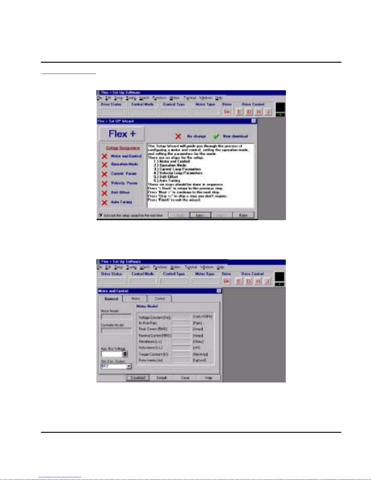
Set up Software Opening menu. Click NEXT to go to the Set up Software. If you have already set
up the parameters and saved them to a file, click FINISH then load the parameter
file using the File ( Open selection.
Start by selecting the Motor and Control and these parameters will be entered automatically for you by
the software for a stock motor. For a custom motor, the motor parameters must be entered on the
general menu. First, click on “Motor” and then select “User Models” in the Library menu. Then, click
“General” to return to this menu and enter all parameters.
MN1276
Operation 5-5
Page 43

There are 7 parts to the setup procedure:
Motor Select your motor from the list. First, select the general “Motor Type”. Then select
your specific “Motor ID”. All of the parameters will be entered if your motor is on
the list. If your motor is not on the list, you must define a motor and all of its
parameters. If your motor is not listed, select “User Models” in the Library menu
and enter the motor parameters. Click “Download” when finished.
Figure 5-2 Motor Selection Screen
Control The “Control ID” is automatically selected. All of the parameters will be entered if
your control is on the list. Click “Download” when finished.
Figure 5-3 Control Selection Screen
5-6 Operation
MN1276
Page 44

After the motor and control are selected, click the General menu and note that the values are filed in.
Operating Mode
Select the operating mode of the control. Choices are:
1. Current Mode
2. Velocity Mode
3. Positioning (15 preset point to point moves)
Click “Download” when finished.
Note: If an encoder with hall feedback is plugged into X9, the handwheel cannot
be used. Only one device may be plugged into X9.
MN1276
Figure 5-4 Operating Mode Selection Screen
Operation 5-7
Page 45

Current Parameter
Nominal and peak current values are automatically entered for the motor type.
For manual tuning only, set the control current limit value to a percentage of the
continuous current rating. For example, if your control is rated for 5A continuous
current and you desire to limit the output current to 4A, enter 80%. If you wish to
use the full output power of the control, enter 100%. Click “Download” when
finished.
Figure 5-5 Current Parameter Screen
Velocity Parameter
Set the velocity parameters of the control:
1. Scale factor - ratio of the input voltage to output RPM.
2. Minimum velocity
3. Time to maximum velocity
Click “Download” when finished.
Figure 5-6 Velocity Parameter Screen
5-8 Operation
MN1276
Page 46
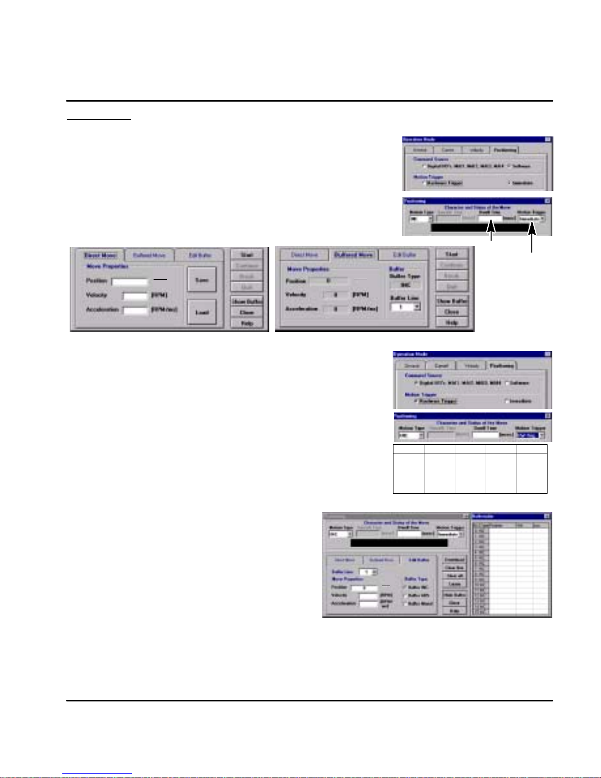
Positioning There are two ways to start a move: Software triggered or Hardware triggered.
Software Triggered (Refer to Section 3 for information on how to setup a move).
1. From the Main menu select “Setup ) Operation Mode”.
2. Click on “Positioning Tab”and set Command Source to “Software”.
3. Set Motion Trigger to “Immediate” then click “Download” and “Close”.
4. From the Main menu select “Motion ) Positioning”.
5. Set Motion Type to “INC” = Incremental or “ABS” = Absolute.
6. Set “Dwell Time” as desired (the wait time before the next move starts).
7. Set Motion Trigger to “Immediate”.
Note: The Motion Trigger must be set to identical values in both of these
8. For Direct move, enter the position, velocity and acceleration parameters.
9. For Buffered move, select “Buffered Move” then select the buffer line number 1--15.
10. Click the Start button to begin (Quit button to stop).
1. From the Main menu select “Setup ) Operation Mode”.
2. Click on “Positioning Tab”and set Command Source to “Digital I/O’s”.
3. Set Motion Trigger to “HW Trig.” then click “Download” and “Close”.
4. From the Main menu select “Motion ) Positioning”.
5. Set Motion Type to “INC” = Incremental or “ABS” = Absolute.
6. Set “Dwell Time” as desired (the wait time before the next move starts).
7. Set Motion Trigger to “HW Trig.”.
8. For a Direct move, enter position, velocity and acceleration parameters.
9. To start a direct move, the external trigger must be present at input X3
10.For a buffered move, the buffer line must be selected by MAI1--4.
11.After the buffer line is selected, the external trigger must be present at
positioning menus. Otherwise, problems will occur.
1
Rev
65536
Hardware Triggered
Note: The Motion Trigger must be set to identical values in both of these
positioning menus. Otherwise, problems will occur.
pin 15.
input X3 pin 15 to start the move.
1
65536
Rev
Buffer
0
1
2
etc.
MAI4
Open
Open
Open
Dwell
Time
MAI3
Open
Open
Open
MAI2
Open
Open
Closed
Motion
Trigger
MAI1
Open
Closed
Open
Initialize Buffers
1. From the Main menu select “Motion ) Positioning”.
2. Select “Edit Buffer”.
3. Set Motion Type, Dwell and Motion Trigger. (Software or
Hardware Triggered).
4. If you want to see the buffer c ontents, click on “Show Buffer”.
5. Define up to 15 moves by selecting the Buffer Line number,
then enter the position, velocity and acceleration for that move.
6. If you want the present absolute position to be stored in a
buffer,select the buffer line number, then click “Learn”.
7. In the box “Edit Buffer” select the “Buffer Type”
(INC = incremental, ABS = absolute or Mixed = absolute +
incremental). Mixed is a combination of absolute and
incremental. The position value in line 0 is an absolute position and is the reference position for the other buffer lines.
Example:
The position values in the buffer lines 2 .. 15 are incremental values.
e.g. Position value in Buffer line 1=1000, Buffer line 2=10.
If you start a move with buffer line one, the control stops the move when the position 1000 is reached.
If you start a move with buffer line two the control stops the move if the position 10 reached.
If you start an incremental move with buffer line 1, then buffer line 2 the control stops the move at position 1010.
MN1276
65536
1
Rev
Operation 5-9
Page 47
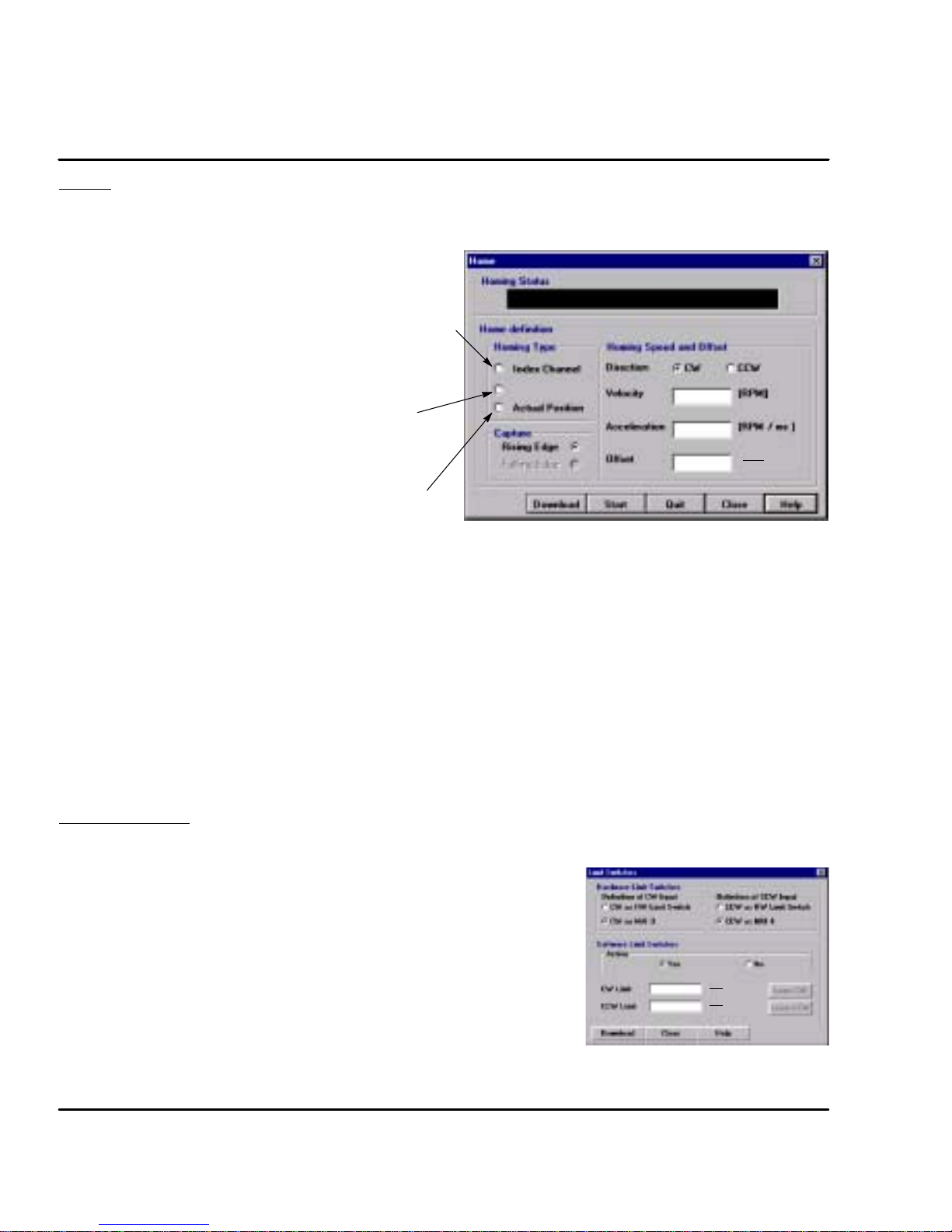
Home Starts a search for the machines absolute zero position. When home is found, the
control will hold the position at absolute zero. There are three Homing types:
Index channel, Capture and Actual Position.
Index Channel causes the motor shaft to rotate to a predefined
home position. The motor may rotate CW or CCW as specified
by the user. Home is located when a machine mounted switch is
activated, then the motor direction is reversed and continues until
the “0” position of the resolver is detected (or the “C” channel of
an encoder). The actual position of “Zero” relative to this point
can be set by the user by changing the offset value.
If home flag is active, clear absolute revolution counter at position
C. Set C (+ HOME.OFFSET) = Zero Position.
Brake with HOME.ACC to zero velocity. Move to Zero.
Capture is a more accurate way to define home position.
The home flag captures the closure of the machine mounted
switch. This captured position (+ HOME.OFFSET) = Zero
Position.
Brake with HOME.ACC to zero velocity. Move back to Zero.
Actual position sets the Zero position to the current position.
No movement required.
Procedure to define home position.
1. Be sure the machine mounted switch (Home position) is connected to X3 pin 14.
2. Select “Homing” from the Motion menu.
3. Choose the desired homing type.
4. Choose the desired capture edge (rising or falling).
5. Choose the desired home direction, CW or CCW.
6. Choose the desired home velocity, acceleration and offset parameters.
7. Click Download.
8. Click the Start button to begin the homing definition (Quit button to stop).
9. To start homing by hardware, buffer line 0 must be selected by MAI1--4.
10. To begin the home move, the external trigger must be present at input X3 pin 15.
Capture
1
65536
Rev
Limit Switches After Homing is set, the limit switches can be activated and set as desired. If the
inputs at X3--10 and X3--11 are used for machine inputs, software limits can be
used to sense when a position limit has been reached.
1. From the Main menu select “Setup ) Limit Switches”.
2. Set “Hardware Limit Switches” as limits switches or as machine inputs.
3. Set the Software Limit Switches, “Active” to Yes or No. Yes activates a software
switch when the position exceeds a predefined limit. No deactivates the software
limit switch feature.
4. If software limit switches are set to Active = Yes, enter a position for the CW limit
and a position for the CW limit.
If you want to take the current absolute position as CW limit or CCW limit, click on
“Learn CW” or “Learn CCW”. The ”Learn” function only works after a successful
homing sequence.
5. Click ”Download” to send the parameters to the control.
Note: The value for the CW limit must be greater than the CCW limit value.
5-10 Operation
65536
65536
1
1
Rev
Rev
MN1276
Page 48

Drift If you know the input offset value of the control, you may enter the value manually.
Otherwise, you may initiate automatic offset tuning and let the control measure
and set this value. Click “Download” when finished.
Figure 5-7 Drift Parameter Screen
Autotune You may manually tune the control (see appendix) or use autotune to allow the
control to tune itself. Click “Download” when finished.
Figure 5-8 Autotune Screen
MN1276
Operation 5-11
Page 49

Main Menu Choice Descriptions
File
Open a new editor window.
Open an existing editor window.
Close the active editor window.
Close all editor windows.
Save the active editor window to a file.
Save the active editor window to a new file name .
Save all editor windows.
Print the contents of the active editor window.
Exit and close the Set up software.
Edit
Cut the selected text in the active editor window to the clipboard.
Copy the selected text in the active editor window to the clipboard.
Paste text from the clipboard at the cursor location in the active editor window.
Erase the contents of the active window.
Select everything in the active window.
Setup
5-12 Operation
Save the active editor window to a new file name .
Allows selection of the motor being used.
Allows selection of Current, Velocity or Positioning modes.
Allows PC to read the control configuration and save the parameters to a file.
Allows PC to read a configuration file and download parameters to the control.
Save the contents of the motion buffer to a file.
Restore a motion buffer file and downloads the parameters to the control.
Select a control for communication (8 maximum in daisy chain).
Not available for this control.
Not available for this control.
Set CW and CCW inputs to MAI3 and MAI4 respectively.
MN1276
Page 50

Tuning
Watch
Functions
Allows manual or automatic tuning to remove offset drift.
Allows manual or automatic tuning of velocity control
parameters.
Show or hide the “symbols list bar”.
Show or hide the “system parameters bar”.
Show or hide the “system status bar”.
Gather and plot motor data for two variables.
View the error log.
View the available options for the selected control.
Enable the control.
Disable the control -- Active: Motor decels to stop then control disables.
Passive: Motor coasts to stop.
Cause motor to stop and maintain position.
Allow you to Jog the position of the motor.
Motion
Terminal
Windows
Define up to 12 PLC statements (logical association of input / output conditions).
Searches for absolute position Zero and hold position at absolute Zero.
Start a positioning move, Direct move or Buffer move.
Allows communication with selected control using command set (see Appendix B).
Configure PC COM port 1, 2, 3 or 4 to communicate with the selected control.
Cascade display of all open software windows.
Tile display of all open software windows.
MN1276
Operation 5-13
Page 51

Alphabetic glossary listing of keywords.
Search for help based on a keyword.
Get help for a specific topic.
Starts the setup wizard to configure a motor and control.
Software version and release information.
PLC Program At the main menu, select “Functions” then “PLC”. See Figure 5-9.
1. Determine which event (listed under the THEN column) you wish to use.
2. Next, click in the IF column on the same ROW as the desired event. For
example, If you are to use the MAO1 output, click in row 1 in the IF
column as shown.
3. Choose the condition for the desired event.
4. Set other event conditions as desired.
5. Activate the PLC by selecting “Enable” on PLC Status.
6. Select “Download” to update the parameter values in the control.
7. Select “Close” when finished.
Note: To reset all IF conditions to False, select “Clear” located just below the
Download selection. This will clear all condition choices.
Figure 5-9 PLC Program Menu
5-14 Operation
MN1276
Page 52

Section 6
Troubleshooting
Overview
The system troubleshooting procedures involves observing the status of the
“Ready” LED, the “DB On” LED and the “Monitor” 7 segment display. The tables
in this section provide information related to the indications provided by these
devices.
Note: The “Ready” LED can display RED, YELLOW or GREEN color.
Table 6-1 Operating Mode Indications
Ready Monitor Status Cause
OFF OFF Control Disabled No Fault.
Green Decimal
Point
Red 1 Over-voltage fault (DC Bus) Missing, damaged or wrong REGEN resistor.
Red 3 Over-current fault.
Red 4 Over or Under-voltage fault. Internal 15VDC supply fault.
Red 5 Resolver fault (or encoder fault). Resolver or cable short circuit or resolver not
Red 6 Electronic fusing
Red 7 I2t limit reached. After a fault is detected,
Red 9 User defined fault (see PLC).
Red 0 Processor “Watchdog” timeout Reset control (turn off AC power, wait 1
Green
Control Enabled Normal operating mode. No Fault.
Input voltage too high.
(More than 2X peak current)
(also see fault 7)
control will run at nominal output current for
2.5seconds then stop.The control isdisabled
and the Monitor will first display “7” fault then
the “6” fault.
Control Over-Temperature
Move Command not accepted. More than two move commands have been
+
*
Motor leads shorted or control failure.
Load exceeds motor rating (too much
current).
Accel time set too short.
connected (open circuit).
Control current over-load detected by
software.
Cycle time between Acceleration and
Deceleration is too short.
Control should be relocated to cooler area.
Add fans or air conditioning to control
cabinet.
minute then turn power on).
sent to the control. To return to normal
status, send a “Quit” or a new move
command to the control.
A non-initialized buffer line has been called
by the Machine inputs. To return to normal
status, call an initialized buffer line by
MA1-4 or send a “Quit” to the control.
Note: To protect the internal fuse, allow at least 1 minute after power down before
turning power on (power Off/On cycle).
Troubleshooting 6-1MN1276
Page 53

Table 6-1 Operating Mode Indications Continued
Ready Monitor Status Cause
Red A EEPROM checksum error. The personality must be downloaded to
Red c Velocity data in the EEPROM failed. The velocity data must be downloaded to
Green C CAN bus problem detected. (“C” blinking) A communication error on the
Red C CAN bus problem detected. (“C” blinking) A communication error on the
Green d Control Disabled. Disable mode activated by hardware or
Green E Following Error. The following error exceeded the user
Green F Fatal Following Error. The following error exceeded the user
Green H Hold-Position mode. Hold mode activated by hardware or
Green J Jog mode. Jog mode activated by hardware or software.
Red L Both limit switches active. Defective or missing limit switch or wiring.
Green P In Position. The following error is less than the user
Red U EPROM version fault. The personality must be downloaded to
Red u EEPROM version fault. The personality must be downloaded to
EEPROM and reset the control. If problem
remains, contact Baldor.
EEPROM and reset the control. If problem
remains, contact Baldor.
CAN bus exists. The control is still
connected to the CAN bus.
CAN bus exists. The control will attempt
resynchronization to establish the CAN bus.
software.
defined value of the Following Error Band.
This error is not stored and goes away when
the following error is reduced to within limits.
defined value of the Following Fatal Error.
The following error preset level is
“Operation Mode ( Pulse Follower”
This error is stored and must be cleared by
the operator, but operation continues as
long as the error is less than "2
software.
defined preset value.
EEPROM and reset the control.
EEPROM and reset the control.
15
("32768).
It is important to connect the motor leads U, V and W correctly at the X1 connector
of the control. Incorrect wiring can cause erratic operation including moves at
peak force until the overcurrent limit trips. This will result in a display of “7” and a
“6” on the monitor. If erratic movement of the motor occurs, turn off power
immediately and check the connections of the motor, hall sensors and encoder.
6-2 Troubleshooting MN1276
Page 54

Section 7
X
X
X
X
X
Specifications & Product Data
Identification
Servo Control
Flex +Drive
Input Voltage
1=115VAC
2=230VAC
4=460/400VAC
Current Rating
A02=2/2.5Amps
A05=5Amps
A07 = 7.5 Amps
A10 = 10 Amps
A15 = 15 Amps
A20 = 20 Amps
A27 = 27.5 Amps
Enclosure T ype
T= Panel Mount w/internal power supply
P= Panel Mount w/external power supply
S = Panel Mount w/internal power supply
(suitableforsharingwithothercontrols).
Braking (Option)
R = Requires external regen resistor
B = Built-in regen resistor
O = No internal regen capability
FP
A
-- R
C
3
4
Logic Supply (Option)
0 = Internal 24VDC Supply
3 = External customer provided
24VDC required
Serial Port Type (Option)
2 = RS232
4 = RS485
Bus (Option)
N = None
C= CAN Bus
Feedback Device (Option)
R= Resolver
E= Encoder
*
* CAN Bus is only available for controls with
resolver feedback. Controls that have encoder
feedback may not have CAN Bus.
Specifications & Product Data 7-1MN1276
Page 55

Specifications
Description Unit FPX
Input Voltage Range Nominal
VAC 115 / 230
A02T
Minimum
Maximum
FPX
A05T
FPX
A07T
FPX ©
A02S
92 / 184
132 / 265
FPX ©
A05S
FPX ©
A010S
FPX ©
A015S
Input Frequency Hz 50/60 "5%
Nominal Output Bus Nominal
(@ 115 / 230 input) Minimum
Maximum
Nominal Phase Current ("10%) A
Peak Phase Current ("10%); for
VDC 160 / 320
88 / 176
180 / 360
2.5 5.0 7.5 2.0 5.0 10 15
5 10 15 4 10 20 30
A
RMS
RMS
2.4sec (+0.5s/--0sec) maximum ¡
Nominal Output Power KVA 1.01 2.17 2.99 0.87 2.17 4.33 5.2
Output Frequency Hz 0 -- 500
Efficiency % >95
Nominal Switching Frequency KHz 8.5
Current Loop Bandwidth Hz 1200
Velocity Loop Bandwidth Hz 10 to 200 (software selectable)
Mounting -- Panel
Package Size -- A B C E E E E
Operating Altitude Feet
(Meters)
To 3300 feet (1000 meters). Derate the continuous and
peak output current by 1.1% for each 330 feet (100
meters) above 3300 feet.
Operating Temperature #C
+0 to 40. Above 40#C, derate the continuous and peak
output current by 2.5% per #C above 40#C. Maximum
ambient is 50#C.
Rated Storage Temperature #C -- 25 to + 70
Humidity % 10% to 90% non-condensing
Class of Protection (Enclosure) IP20
Shock 10G (according to DIN IEC 68--2--6/29)
Vibration 1G @ 10 -- 150 Hz (according to DIN IEC 68--2--6/29)
¡ Valid for zero current initial condition.
© These specifications also apply to model FPxAxxP except it has DC input (no AC input).
All values at ambient temperature of 25# C unless otherwise stated.
For safe operation, allow a clearance distance between each control and on all sides of each control.
7-2 Specifications & Product Data MN1276
Page 56

Specifications Continued
Description Unit FP4
Input Voltage Range Nominal
VAC 460 @ 60Hz / 400 @ 50Hz
A02TB
Minimum
Maximum
FP4
A05TB
FP4
A07TB
400 / 360
528 / 480
FP4
A15TR
FP4
A20TR
FP4
A27TR
Input Frequency Hz 50/60 "5%
Nominal Output Bus Nominal
(@ 400 / 460 input) Minimum
Maximum
Nominal Phase Current ("10%) A
Peak Phase Current ("10%);
VDC 565 / 678
509 / --
-- / 746
2.5 5 7.5 15 20 27.5
5 10 15 30 40 55
A
RMS
RMS
1.25s +0.25s/--0s ¡
Nominal Output Power KVA 1.9 3.8 5.7 11.4 15.2 20.9
Output Frequency Hz 0 -- 500
Efficiency % >95
Nominal Switching Frequency KHz 8.0
Current Loop Bandwidth Hz 1200
Velocity Loop Bandwidth Hz 10 to 200 (software selectable)
Mounting -- Panel
Package Size -- G G G H H H
Operating Altitude Feet
(Meters)
To 3300 feet (1000 meters). Derate the continuous and
peak output current by 1.1% for each 330 feet (100
meters) above 3300 feet.
Operating Temperature #C
+0 to 40. Above 40#C, derate the continuous and peak
output current by 2.5% per #C above 40#C. Maximum
ambient is 50#C.
Rated Storage Temperature #C -- 2 5 to +7 0
Humidity % 10% to 90% non-condensing
Class of Protection (Enclosure) IP20
Shock 10G (according to DIN IEC 68--2--6/29)
Vibration 1G @ 10 -- 150 Hz (according to DIN IEC 68--2--6/29)
¡ Valid for zero current initial condition.
All values at ambient temperature of 25# C unless otherwise stated.
For safe operation, allow a clearance distance between each control and on all sides of each control.
MN1276
Specifications & Product Data 7-3
Page 57

24VDC Logic Power Input (Option FPxAxxxx--xxx3 ONLY)
Description Unit FPX
A02T
FPX
A05T
FPX
A07T
FPX
A02S
A05S
Input Voltage (maximum ripple = "10%) VDC 20 -- 30
Input Current @ 24VDC A
Power On surge current (24VDC 100msec) A
RMS
RMS
0.55 -- 0.8 ¡
4.0 2.5
¡ Depends on installed options.
24VDC Logic Power Input Continued (Option FP4Axxxx--xxx3 ONLY)
Description Unit FP4
A02
Input Voltage (maximum ripple = "10%) VDC 20 -- 30
Input Current @ 24VDC A
Power On surge current (24VDC 100msec) A
RMS
RMS
0.8 1.0 1.0 1.4 1.6 1.6
FP4
A05
FP4
A7
FP4
A15
4.0
Velocity Control
Description Unit All
Command Input VDC 0 to 10; or "10
Command Signal Resolution bit 12
Update Rate
msec
500
Resolver Feedback
Description Unit All
Resolution
(Automatically set by software. Depends on
maximum speed.)
Pole Pairs 1
Resolver Winding Ratio 0.5
bit Velocity < 6100RPM ( Resolution 14 bits
Velocity > 6100RPM ( Resolution 12 bits
FPX
1.4
FPX
A10S
FP4
A20
FPX
A15S
FP4
A27
Simulated Encoder Output
Description Unit All
Signal RS422
Encoder Resolution ppr
7-4 Specifications & Product Data
512 / 1024 ¡ / 2048 / 4096
¡ Factory Setting
MN1276
Page 58

Encoder Input (Handwheel or Feedback)
Description Unit All
Signal Type RS422
Operating Mode A/BQuadrature
Maximum Input Frequency kHz 125
Cycle Time msec 1
Serial Interface (Option FPXAXXXX--XX2X)
Description Unit All
Communication Type RS232C (not galvanically isolated)
Transmission Rate Baud 9600 (not adjustable)
Optional Interface (Option FPXAXXXX--XX4X)
Communication Type RS485 (not galvanically isolated)
Transmission Rate Baud 9600 (not adjustable)
Regeneration (115 / 230VAC)
Description Unit FPX
A02T
Switching Threshold
VDC
115VAC
230VAC
ON: OFF:
188 - 195 183 - 188
373 - 383 362 - 372
FPX
A05T
FPX
A07T
FPX
A02S
ON: OFF:
180 200
388 375
FPX
A05S
FPX
A10S
FPX
A15S
Nominal / Peak Power (10% Duty Cycle) kW 0.25 / 2.7
Maximum Regeneration Switching Current A 10
Maximum Load Inductance
mH
100
Regeneration (400 / 460VAC)
Description Unit FP4
A02
Switching Threshold 400/460VAC VDC ON: 794 OFF: 787 ON: 794 OFF: 764
Nominal / Peak Power (10% Duty Cycle) kW 0.94 / 9.4 2.9 / 29
Maximum Regeneration Switching Current A 15 45 40 80
Maximum Load Inductance
mH
FP4
A05
FP4
A07
100
FP4
A15
FP4
A20
FP4
A27
MN1276
Specifications & Product Data 7-5
Page 59

Dimensions
A
Size A, B and C
1.57'
(40mm)
Size E, G and H
A
W
7.70'
(195.5mm)
6.81'
(173mm)
0.2 (5.2) Dia.
4Places
0.12 (3.0)
Clearance Requirements (all sizes):
0.06' (15mm) top and bottom
0.04' (10mm) left and right side
W
15.75
(400)
15.14
(385)
14.05
(357)
Depth
Size A, B, C = 6.0 (152)
0.374 (9.5)
X
Package
Size
A
A w/CAN option
B
B w/CAN option
C
E
G
H
0.59 (15)
0.59 (15)
0.90 (23)
0.90 (23)
0.90 (23)
1.08 (27.5)
1.28 (32.5)
2.6 (65)
Dimensions in (mm)
WA
2.6 (67.5)
3.3 (84.0)
3.6 (92.5)
4.3 (109)
4.3 (109)
2.17 (55)
2.6 (65)
5.3(130)
For safe operation, allow a clearance distance between each control and on all sides of each control.
7-6 Specifications & Product Data
X
--
--
--
--
--
1.42 (36)
1.81 (46
4.37 (111)
0.3
(8.0)
Weight lb (kg)
2.73 (1.24)
3.17 (1.44)
4.69 (2.13)
5.06 (2.3)
4.8 (2.19)
11 (5)
10.1 (4.6)
20.9 (9.5)
0.25 (6.5) Dia. 3 Places
Depth
Size E, G and H = 10.4 (265)
MN1276
Page 60
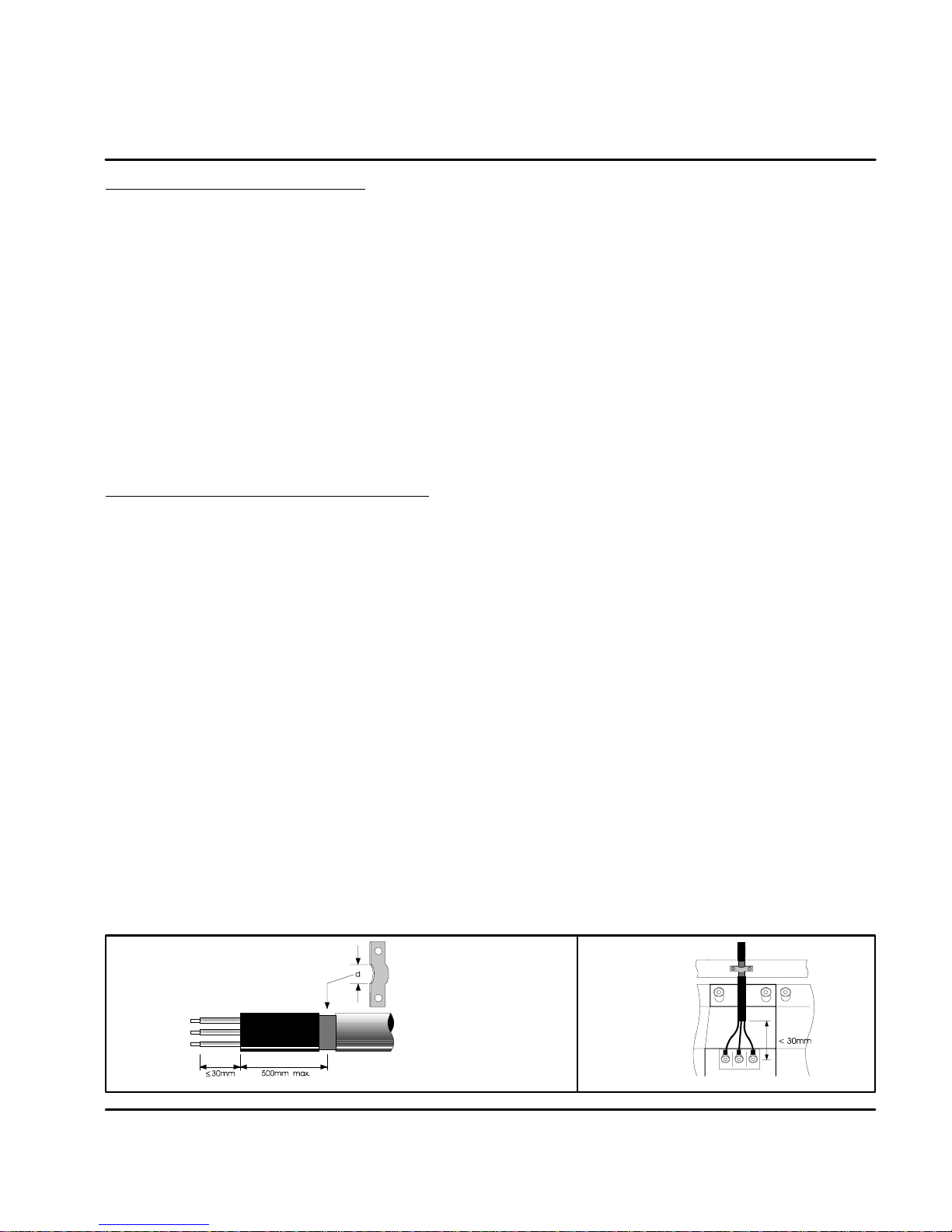
Section 8
CE Guidelines
CE Declaration of Conformity
Baldor indicates that the products are only components and not ready for
immediate or instant use within the meaning of “Safety law of appliance”, “EMC
Law” or “Machine directive”.
The final mode of operation is defined only after installation into the user’s
equipment. It is the responsibility of the user to verify compliance.
The product conforms with the following standards:
DIN VDE 0160 / 05.88 Electronic equipment for use in electrical power
DIN VDE 0100 Erection of power installations with nominal
DIN IEC 326 Teil 1 / 10.90 Design and use of printed boards
DIN VDE 0110Teil 1-2 / 01.89 Dimensioning of clearance and creepage
DIN VDE 0110Teil 20 / 08.90 distances
EN 60529 / 10.91 Degrees of protection provided by enclosures
EMC -- Conformity and CE -- Marking
The information contained herein is for your guidance only and does not
guarantee that the installation will meet the requirements of the council directive
89/336/EEC.
The purpose of the EEC directives is to state a minimum technical requirement
common to all the member states within the European Union. In turn, these
minimum technical requirements are intended to enhance the levels of safety both
directly and indirectly.
Council directive 89/336/EEC relating to Electro Magnetic Compliance (EMC)
indicates that it is the responsibility of the system integrator to ensure that the
entire system complies with all relative directives at the time of installing into
service.
Motors and controls are used as components of a system, per the EMC directive.
Hence all components, installation of the components, interconnection between
components, and shielding and grounding of the system as a whole determines
EMC compliance.
The CE mark does not inform the purchaser which directive the product complies
with. It rests upon the manufacturer or his authorized representative to ensure the
item in question complies fully with all the relative directives in force at the time of
installing into service, in the same way as the system integrator previously
mentioned. Remember, it is the instructions of installation and use, coupled with
the product, that comply with the directive.
installations
voltages up to 1000V
Wiring of Shielded (Screened) Cables
Remove the outer insulation
to expose the overall screen.
Conductive
Clamp
CE Guidelines 8-1MN1276
Page 61
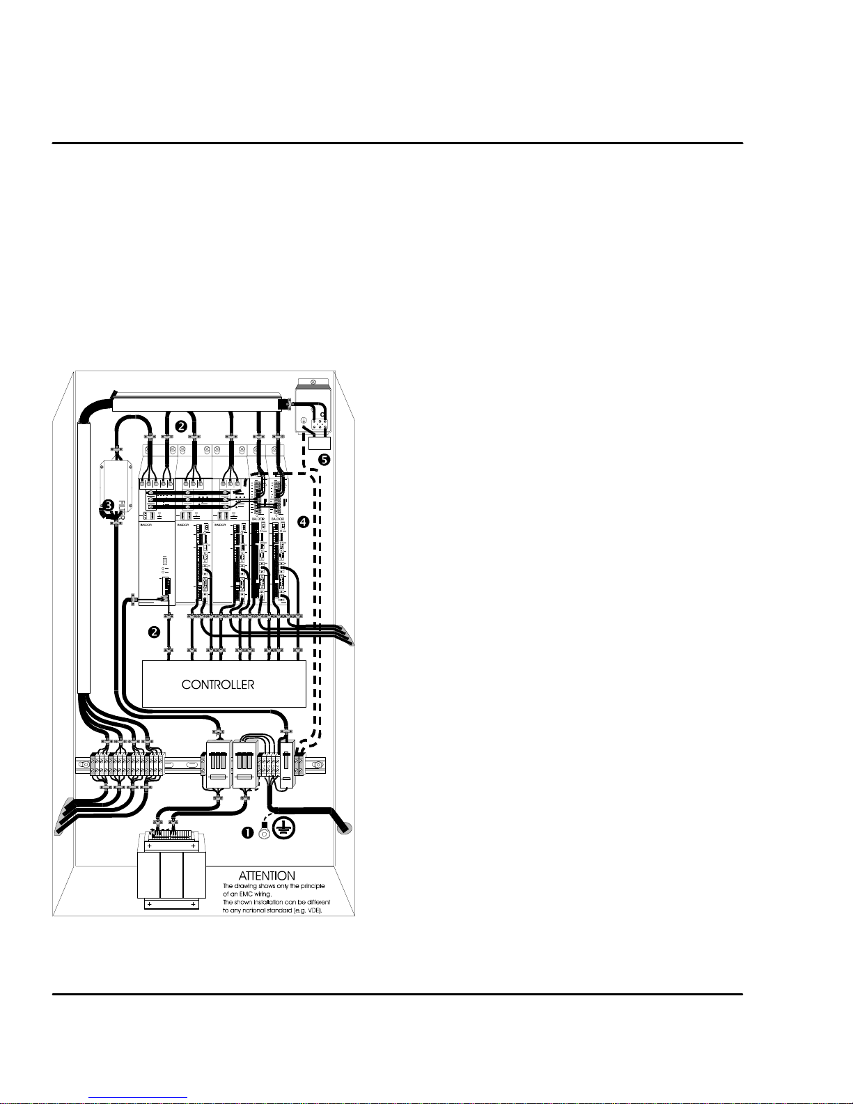
Using CE approved components will not guarantee a CE compliant system!
1. The components used in the drive, installation methods used, materials
selected for interconnection of components are important.
2. The installation methods, interconnection materials, shielding, filtering
and grounding of the system as a whole will determine CE compliance.
3. The responsibility of CE mark compliance rests entirely with the party
who offers the end system for sale (such as an OEM or system
integrator).
Baldor products which meet the EMC directive requirements are indicated with a
“CE” mark. A duly signed CE declaration of conformity is available from Baldor.
EMC Wiring Technique
1 CABINET
The drawing shows an electroplated zinc coated enclosure,
Capacitor
Y
which is connected to ground.
This enclosure has the following advantages:
-- All parts mounted on the back plane are connected to ground.
-- All shield (screen) connections are connected to ground.
Within the cabinet there should be a spatial separation between
power wiring (motor and AC power cables) and control wiring.
2 SCREEN CONNECTIONS
All connections between components must use shielded cables.
The cable shields must be connected to the enclosure. Use
conductive clamps to ensure good ground connection. With this
technique, a good ground shield can be achieved.
3 EMC -- FILTER
The EMI or main filter should be mounted next to the power
supply (here BPS). For the connection to and from the main
filter screened cables should be used. The cable screens should
be connected to screen clamps on both sides. (Exception:
Analog Command Signal).
4 Grounding (Earth)
For safety reasons (VDE0160), all BALDOR components must
be connected to ground with a separate wire. The diameter of
the wire must be at minimum AWG#6 (10mm@). Ground
connections (dashed lines) must be made from the central
ground to the regen resistor enclosure and from the central
ground to the Shared Power Supply.
5 Y--CAPACITOR
The connection of the regeneration resistor can cause RFI (radio
frequency interference) to be very high. To minimize RFI, a
Y--capacitor is used. The capacitor should only be connected
between the dynamic brake resistor housing and terminal pin R1
(lead from Flex).
Recommendation: 0,1,F / 250VAC Type: PME265
BALDOR--Ordering--No.: ASR27104
8-2 CE Guidelines MN1276
Page 62
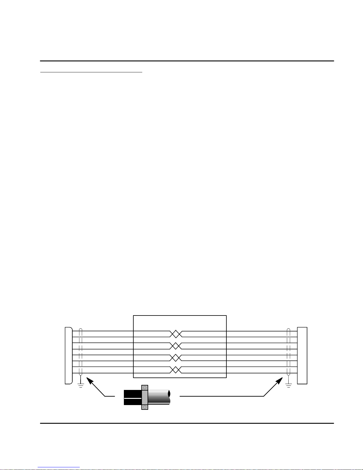
EMC Installation Instructions
To ensure electromagnetic compatibility (EMC), the following installation
instructions should be completed. These steps help to reduce interference.
Consider the following:
$ Grounding of all system elements to a central ground point
$ Shielding of all cables and signal wires
$ Filtering of power lines
A proper enclosure should have the following characteristics:
A) All metal conducting parts of the enclosure must be electrically
connected to the back plane. These connections should be made with a
grounding strap from each element to a central grounding point . ¡
B) Keep the power wiring (motor and power cable) and control wiring
separated. If these wires must cross, be sure they cross at 90 degrees to
minimize noise due to induction.
C) The shield connections of the signal and power cables should be
connected to the screen rails or clamps. The screen rails or clamps
should be conductive clamps fastened to the cabinet. ©
D) The cable to the regeneration resistor must be shielded. The shield must
be connected to ground at both ends.
E) The location of the AC mains filter has to be situated close to the drive
so the AC power wires are as short as possible.
F) Wires inside the enclosure should be placed as close as possible to
conducting metal, cabinet walls and plates. It is advised to terminate
unused wires to chassis ground. ¡
G) To reduce ground current, use at least a 10mm
ground connections.
¡ Grounding in general describes all metal parts which can be connected to a protective
conductor, e.g. housing of cabinet, motor housing, etc. to a central ground point. This
central ground point is then connected to the main plant (or building) ground.
© Or run as twisted pair at minimum.
2
(6 AWG) solid wire for
MN1276
Cable Screens Grounding
Cable (Twisted Pair Conductors)
Conductive Clamp -- Must contact bare cable shield
and be secured to metal backplane.
CE Guidelines 8-3
Page 63
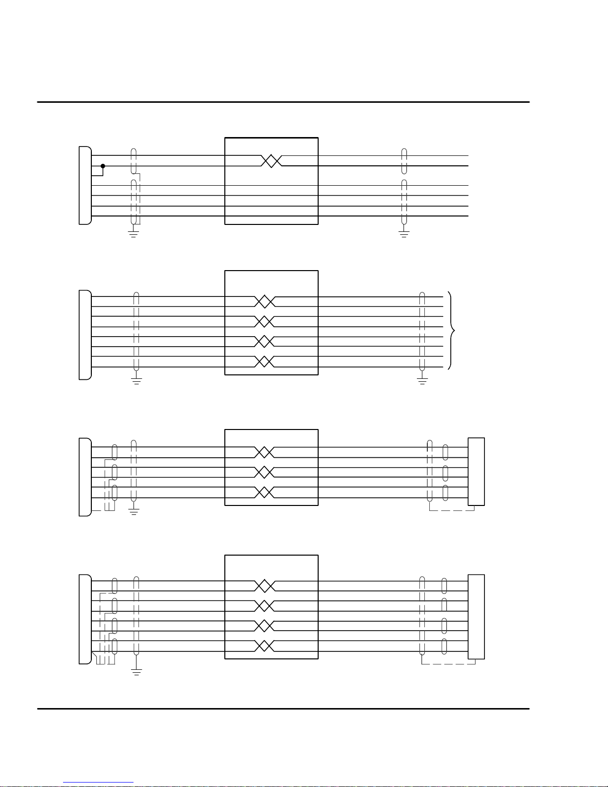
Control
X3
1
2
3
7
9
10
11
Input Signal Cable Grounding
Cable
Control
X7
1
6
2
7
3
8
11
13
Control
X8
1
6
2
7
3
8
5
Control
X9
1
6
2
7
3
8
11
13
Simulated Encoder Output Cable Grounding
Cable
Resolver Cable Grounding
Cable
Connection of shields to analog ground is optional.
Encoder Cable Grounding
Cable
To
Controller
Resolver Connector
Housing
1
2
3
4
5
6
Encoder Connector
Housing
Connection of shields to digital ground is optional.
8-4 CE Guidelines
MN1276
Page 64

Section 9
CableAssembly
Accessories and Options
Cables Shielded (Screened) cable provides EMI / RFI shielding and are required for
compliance to CE regulations. All connectors and other components used must
be compatible with this shielded cable.
Motor Power Cable
Cable Rated Current
20 Amps
30 Amps
Description
Power Cable Assembly
Threaded connector
(Standard-Metric Style)
Power Cable Assembly
Quick Connect Style
Power Cable Assembly
CE Style Threaded
Connector
Power Cable
No Connectors
Power Cable
No Connectors
Baldor Catalog Number
CBL015SP--FHM
CBL030SP--FHM
CBL046SP--FHM
CBL061SP--FHM
CBL076SP--FHM
CBL152SP--FHM
CBL015SP--FHQ
CBL030SP--FHQ
CBL046SP--FHQ
CBL061SP--FHQ
CBL076SP--FHQ
CBL152SP--FHQ
CBL030SP--FHCE
CBL061SP--FHCE
CBL091SP--FHCE
CBL152SP--FHCE
CBL030SP--F
CBL046SP--F
CBL061SP--F
CBL076SP--F
CBL091SP--F
CBL152SP--F
CBL030SP--E
CBL046SP--E
CBL061SP--E
CBL091SP--E
CBL152SP--E
Length
Feet Meters
5
10
15
20
25
50
5
10
15
20
25
50
10
20
30
50
10
15
20
25
30
50
10
15
20
30
50
1.5
3.0
4.6
6.1
7.6
15.2
1.5
3.0
4.6
6.1
7.6
15.2
3.0
6.1
9.1
15.2
3.0
4.6
6.1
7.6
9.1
15.2
3.0
4.6
6.1
9.1
15.2
Connectors
Mating Connector by connector number (for spare parts)
X1 -- #ASR29714 (9 pin, Female) Phoenix Part No. MVSTBW2,5/9--ST
X1 -- #ASR29715 (2 pin, Female) Phoenix Part No. MVSTBW2,5/2--ST
X3 -- #ASR16000 (20 pin, Female) Phoenix Part No. MVSTBR2,5/20--ST
X6 -- #ASR16215 (9 pin, Male)
X7 -- #ASR16215 (9 pin, Male)
X8 -- #ASR23345 (9 pin, Female) Resolver
X9 -- #ASR25828A (15 pin, Male) Encoder
Accessories & Options 9-1MN1276
Page 65

Resolver Feedback Cable
y
M
CableAssembly
Bal
dorC
otorType
Resolver Feedback Cable
Resolver Feedback Cable
BSM 50/63/80/90/100
Resolver Feedback Cable
Resolver Feedback Cable
BSM 50/63/80/90/100
CableAssembl
Description
Assembly
Threaded connector
(Standard-Metric Style)
Assembly
Quick Connect Style
Assembly CE Style
Threaded Connector
No Connector
atalogNumber
CBL015SF--ALM
CBL030SF--ALM
CBL046SF--ALM
CBL061SF--ALM
CBL076SF--ALM
CBL152SF--ALM
CBL015SF--ALQ
CBL030SF--ALQ
CBL046SF--ALQ
CBL061SF--ALQ
CBL076SF--ALQ
CBL152SF--ALQ
CBL030SF--ALCE
CBL061SF--ALCE
CBL091SF--ALCE
CBL152SF--ALCE
CBL030SF--A
CBL061SF--A
CBL091SF--A
CBL152SF--A
Length
Feet Meters
5
10
15
20
25
50
5
10
15
20
25
50
10
20
30
50
10
20
30
50
1.5
3.0
4.6
6.1
7.6
15.2
1.5
3.0
4.6
6.1
7.6
15.2
3.0
6.1
9.1
15.2
3.0
6.1
9.1
15.2
EMC AC Mains Filter AC filters remove high frequency noise to protect the control. These filters
also prevent high frequency signals from being transmitted back onto the power
lines and help meet CE requirements. To select the proper filter, you must know
the voltage and current used by the drive and the impedance of the AC line.
For package size A, B and C (Model T -- 1 Phase)
Filter Type Rated Volts
FN 2070 - 12 250 12 0.4 1.61 (0.73) 30548
Rated
Amps
@40#C
For package size E, G and H (Model S -- 3 Phase)
Filter Type Rated Volts
FN351-8-29 440 8 16 8.0 3.97 (1.8) ASR24667
FN 351 - 16 - 29 440 16 16 9.0 3.97 (1.8) ASR24668
FN 351 - 25 - 33 440 25 170 9.0 6.61 (3.0) ASR24669
FN 351 - 36 - 33 440 36 170 10.5 6.61 (3.0) ASR24670
FN 351 - 50 - 33 440 50 190 12.5 6.83 (3.1) ASR24671
Rated
Amps
@40#C
Leakage
Current mA
Leakage
Current mA
Power
Losses
Watts
Weight
lbs (kg)
Weight
lbs (kg)
Baldor No.
Baldor No.
9-2 Accessories & Options MN1276
Page 66

For package size E, G and H (Model T -- 3 Phase Required for FP4xx)
Filter Type Rated Volts
Amps
@40#C
FN 3258 - 30 - 47 480 30 184.7 2.64 (1.2) ASR30521
FN 3258 - 7 - 45 480 7 172.4 0.11 (0.5) ASR30522
Rated
Leakage
Current mA
Weight
lbs (kg)
Baldor No.
AC Filter Dimensions Continued
Dim. For For Filters: FN 351 -
FN350 8 - 29 16 - 29 25 - 33 36 - 33 50 - 33
A 5.4 8.6 9.45 9.84
(139) (220) (240) (250)
B 3.9 7.1 7.87 7.87
(99) (180) (200) (200)
C 4.2 4.5 5.9 5.9
(105) (115) (150) (150
D 3.32 3.35 4.7 4.72
(84.5) (85) (119.5) (120)
E 3.73 3.93 5.31 5.31
(95) (100) (135) (135)
F 2.24 2.36 2.55 2.55
(57) (60) (65) (65)
G 0.39 0.39 0.39 0.78
(10) (10) (10) (20)
H 1.74 0.76 1.22 0.83
(19) (19.5) (31) (21)
AC Filter Dimensions Continued
Dim. For Filters:
FN3358- 7- 45 FN3358- 30- 47
A 7.48 10.63
(190) (270)
B 6.29 9.45
(160) (240)
C 7.08 10.04
(180) (255)
D 0.79 1.18
(20) (30)
E 0.18 0.21
(4.5) (5.4)
F 2.75 3.35
(70) (85)
G 1.57 1.97
(40) (50)
Depth = F
G
G
H
M6
F
M5
D
E
G
4.53 (115)
D
C E
B
A
B
A
MN1276
C
Accessories & Options 9-3
Page 67

Regeneration Resistor
Control
Control
Some controls are shipped with an internal regen resistor. If an internal resistor is
not present, a regeneration resistor should be installed to dissipate energy during
braking if a Fault “1” (over-voltage) occurs.
Baldor Catalog Number
Control
Rated
Amps
Size
2.5 A RG27 44 RG56 44
5 B RG27 44 RG56 44
7.5 C RG22 100 RG39 100
2.5 G *RG68 320
5 G *RG68 320
7.5 G RG68 320
15 H RG27A 320
20 H RG11 640
27.5 H RG11 640
2 E RG4.7 320 RG10 320
5 E RG4.7 320 RG10 320
10 E RG4.7 320 RG10 320
15 E RG4.7 320 RG10 320
115VAC Controls 230VAC Controls 400/460VAC Controls
Resistor
Catalog
No.
Resistor
Watts
Resistor
Catalog
No.
Resistor
Watts
Resistor
Catalog
No.
Resistor
Watts
* These controls have a 200 ohm, 50 watt resistor installed (internal).
An RG68 resistor can be installed in parallel for additional capability.
1.7 (45)
3.9
(100)
3.54
(90)
L
2.6 (65)
5.5 (140) for 44 watt
L=
8.9 (228) for 100 watt
13.2 (337) for 320/640 watt
M4
Clearance Requirements (all sizes):
2' (51mm) top and bottom
1' (26mm) left and right side
For safe operation, allow a clearance distance between each control and on all sides of each control.
9-4 Accessories & Options
MN1276
Page 68

CAN Bus (Optional -- Not available for controls with encoder feedback)
Controls that are supplied with the CAN bus option have two additional
connectors, X10 and X11 (conform to DS102, version 2.0). These are shown in
Figure 9-1. CAN is a factory installed option.
Figure 9-1 CAN Bus Connectors
Monitor
1
2
3
4
5
6
7
8
Note: On some models, the width of the
control may increase slightly when
equipped with the CAN option.
NC
L
N
U
V
W
R1
R2
X1
AS1
Off/On
Ready
+24V
0V
DB On
Encoder In X9RS232 / 485 X6Encoder Out X7Resolver In X8
X10 - CAN Bus
1 Reserved 6 GND
CAN X10CAN X11
2CAN_L 7CAN_H
3 GND 8 Reserved
4 Reserved 9 VCC
5 Reserved
X11 - CAN Bus
1 Reserved 6 GND
2CAN_L 7CAN_H
3 GND 8 Reserved
4 Reserved 9 VCC
5 Reserved
MN1276
X3
Accessories & Options 9-5
Page 69

Figure 9-2 CAN Bus Interconnections
Flex Control
X10 X11
X10-7 X10-2 X11-7 X11-2
X10-3
CAN_H
CAN_L
120W 120W
CAN_H
Terminate the
last drive
CAN Bus Protocol
Baldor uses CAN_OPEN, DS 301 protocol.
Baud rate is preset to 125kbit/second may be changed by AS1 switch settings or
serial command (e.g. command: CAN.BD = 1000 for 1Mbit/sec). Available baud
rates are: 10, 20, 50, 100, 125, 250, 500, 800, and 1000kbit/sec.
NODE_ID may be changed by switch settings or serial command (e.g. command:
CAN.ID = 50). Available addresses are 1 to 127.
CAN Bus Features
The following features are available with the Baldor CAN_OPEN structure:
S
S Two PDO’s; each for transmit and receive (synchronous or asynchronous)
S SYNC message
S EMERGENCY object
S Default and variable PDO mapping
S All ID’s can be set with SDO
S
S Simple boot-up
GND
CAN_L
One SDO
Node guarding
Flex Control
X10 X11
X10-7 X10-2
X10-3
GND
CAN_H
X11-7 X11-2
CAN_L
X10-3
CAN_H
GND
CAN_L
CAN
MASTER
GND
CAN_H
Terminate the
Master
CAN_L
9-6 Accessories & Options
MN1276
Page 70

Index Range The index range from 0x1000 to 0x100D is valid.
The following index ranges are important:
0x1400 1st PDO receive (communication)
0x1402 2nd PDO receive (communication)
0x1600 1st PDO receive (mapping)
0x1602 2nd PDO receive (mapping)
0x1800 1st PDO transmit (communication)
0x1802 2nd PDO transmit (communication)
0x1A00 1st PDO transmit (mapping)
0x1A02 2nd PDO transmit (mapping)
Object Entries The following object entries are available with PDO:
-- Read position (absolute and resolver position)
-- Read and write velocity
-- Read status
-- Write torque
The following object entries are available with SDO:
-- Variables and commands
Getting Started with CAN_OPEN
The CAN message transmission consists of an address (=Identifier = ID) followed
by 0 to 8 Data bytes. CAN drives use the following addresses (according to
CAN_OPEN, DS301):
PDO1 (Receive, Master to Drive): 0x200 + Node_ID
PDO2 (Receive, Master to Drive): 0x300 + Node_ID
PDO1 (Transmit, Drive to Master): 0x180 + Node_ID
PDO2 (Transmit, Drive to Master): 0x280 + Node_ID
MN1276
NMT: 0x000
SYNC: 0x80
EMERGENCY: 0x80 + Node_ID
SDO (Master to Drive): 0x600 + Node_ID
SDO (Drive to Master): 0x580 + Node_ID
PDO = Process data transfer, fast communication ex: velocity command.
SDO = Service data transfer, slow communication to access all parameters inside the drive.
NMT = Network management task, to switch the PDOs free and to reset the drive.
SYNC = Specific CAN_OPEN message to do some synchronization.
EMERGENCY: The drive will send this message automatically if a fatal drive error occurs
Node_ID: Special setting (= drive number) for each drive. Range : 1 to 127
Accessories & Options 9-7
Page 71

The default Baud rate is set to 125 kbit/second and the Node_ID is the drive
address+1 (AS1 switches 1 to 4).
Note: Every drive, connected to one CAN Bus system must have a different
Node_ID.
After power up you will receive an EMERGENCY message with two data bytes
(0x00 and 0x00) to inform you that the CAN_DRIVE is now active.
Now you will have access to all commands via SDO. If you want to give a
command or set a parameter, you have to put the following message on the
CAN_BUS:
To send a command or set a parameter in the drive:
D0 D1 D2 D3 D4 D5 D6 D7
0x20 Ind_lo Ind_hi Sub XXX XXX XXX XXX
ID = 0x600 + NODE_ID <--------------------------------------------
0x20
Ind_lo Ind_hi Sub XXX XXX XXX XXX
ID = 0x580 + NODE_ID <--------------------------------------------
Where:
X Data bytes (to write a parameter)
ID Identifier
0x Hexadecimal data format
D0-D7 Databyte0to7ofCANmessage
Ind_lo Low byte of Index of Object dictionary
Ind_hi High byte of Index of Object dictionary
Sub Subindex of Object dictionary. If Object has only one entry, Subindex must always be 0
DrivePC Master
Note: If the first data byte in the returned message from the drive = 0x80, the
9-8 Accessories & Options
commanded action failed.
MN1276
Page 72

To read a parameter from the drive:
D0 D1 D2 D3 D4 D5 D6 D7
0x40 Ind_lo Ind_hi Sub XXX XXX XXX XXX
ID = 0x600 + NODE_ID <--------------------------------------------
0x60
Ind_lo Ind_hi Sub 0x00 0x00 0x00 0x00
ID = 0x580 + NODE_ID <--------------------------------------------
Where:
X Don’t care
ID Identifier
0x Hexadecimal data format
D0-D7 Databyte0to7ofCANmessage
Ind_lo Low byte of Index of Object dictionary
Ind_hi High byte of Index of Object dictionary
Sub Subindex of Object dictionary. If Object has only one entry, Subindex must always be 0
P_lsb Low byte of requested parameter
P_msb High byte of requested parameter
Note: If the first data byte in the returned message from the drive = 0x80, the
commanded action failed.
To send a velocity command to the drive:
1. Verify that the correct motor and drive parameters and operating mode
are set. This is done by CAN or RS232 communications.
2. Send the following CAN messages to the drive.
DrivePC Master
ID
0x601
0x581
D0 D1 D2 D3 D4 D5 D6 D7
0x20 0x8F 0x21 0x00 0x08 XXX XXX XXX
0x60
0x20 0x83 0x21 0x00 XXX XXX XXX XXX0x601 Enable drive.
0x60 0x8F 0x21 0x00 0x00 0x00 0x00 0x000x581 Drive response with “OK”.
0x20 0x90 0x20 0x00 Vl Vm XXX XXX0x601 Velocity command (Vl=lsb; Vm=msb. Scaling=bits/msec)
0x60 0x8F 0x21 0x00 0x00 0x00 0x00 0x000x581 Drive response with “OK”.
0x8F 0x21 0x00 0x00 0x00 0x00 0x00
Description
Select CAN card for velocity command.
Drive response with “OK”.
Note: Every command is answered by the drive. Allow time for the response.
Summary:
With a CAN_OPEN master you don’t need to know each data byte. Therefore you
only should be informed about the object dictionary, which you will find in the
Appendix.
Appendix: Object dictionary
ASCII command set description
MN1276
Accessories & Options 9-9
Page 73

Identifiers and object list
The distribution of the identifiers of the supported objects conforms to Can Open
(DS301, V 3.0, S. 8--12).
Message / Object Function Code COB - Identifier Services
Start_Remote_Node
NMT Services 0 0 (broadcast)
Sync. Emergency
PDO1 (tx) 384 + Node_ID Transmit PDO (asynchronous)
PDO1 (rx) 512 + Node_ID Receive PDO (asynchronous)
PDO2 (tx) 640 + Node_ID Transmit PDO (synchronous)
PDO2 (rx) 768 + Node_ID Receive PDO (synchronous)
SDO (tx) 1408 + Node_ID Transmit SDO
SDO (rx) 1536 + Node_ID Receive SDO
Node guarding 1760 NMT node guarding
1
1
128 (broadcast)
128 + Node_ID
Node_ID is the node identifier, which is the card--address (set by switch AS1--4).
SDO Protocols (CMS Multiplexed Domain Protocols)
In CiA/DS202--2 CMS protocol specification, the following specifications of the
SDO COB identifier. This protocol specifies the meaning of the content of the 8
data bytes transferred within a CAN Message for the different domain protocols.
Stop_Remote_Node
Pre-Operational-State
NMT_Reset_Node
NMT_Reset_Com
Synchronization
Emergency (fault)
Byte 1
Protocol
Control Bits
Byte 2
index, lsb
Byte 3
Multiplexer or Data Bytes
index, msb
Byte 4
sub-index
Byte5toByte8
up to 4 Data Bytes
Data (byte 5 is lsb; byte 8 is msb)
Multiplexed: Same identifier, message indication by Index + Subindex
Expedited: Used, if data to be transported is less or equal 4 byte (long int, 32 Bit)
The following tables list the meaning / setting of the control bits of first byte (x =
not used, always 0) to select the protocol and the correspondent meaning of the
further 7 data bytes of the CAN frame.
9-10 Accessories & Options
MN1276
Page 74

Expedited domain download and initiate domain download
Domain Protocols
Expedited Domain Download
Request
Confirm
Initiate Domain Download
Request
Confirm
7..5:
ccs 001
scs 011
ccs 001
scs 011
4:
x
x
x
x
3..2:n
(0 or n)
x
x
x
1:e
1
x
0
x
n: If e=1 & s=1, n indicates the number of bytes, which do not contain data
(therefore only valid for expedited protocol)
s: Data set size is not indicated / indicated: 0 / 1
1
If s=1, the 1.byte contains: 23 or (n shifted 2 left)
2
If s=1, the 4 data bytes contain the number of data bytes to be transferred in
the segmented domain.
Segmented domain download
Domain Protocols
Download Domain Segment
Request
Confirm
End of Download Domain Segment
Request
Confirm
7..5:
ccs 000
scs 001
ccs 000
scs 001
4: t
0/1
0/1
0/1
0/1
3..1:n
n
x
n
x
t: Toggle bit of segmented domain, with first download domain segment
t=0
n: n indicates the number of bytes, which do not contain data
c: 1 if last segment to be downloaded, else 0
3
The1.bytecontains:01or(nshifted1left)
0:s
0:c
=1.byte
s
=22, 2x1
x
=60
s
=20, 2x2
x
=60
=1.byte
0
=00 / 10
x
=20 / 30
1
=0X / 1X
=20 / 30
x
m
multiplexor
multiplexor
up to 3+
7 data bytes to be downloaded
Reserved
3
<7 data bytes to be downloaded
Reserved
up to 4 data bytes
datatobe
downloaded
if s=1: number of
data reserved
up to 4 data bytes
Expedited domain upload and initiate domain upload
Domain Protocols
Expedited Domain Upload
Request
Confirm
Initiate Domain Upload
Request
Confirm
7..5:
ccs 001
scs 010
ccs 001
scs 010
4: t
3..1:n
x
x
x
x
x
(0 or n)
x
0
n: If e=1 & s=1, n indicates the number of bytes, which do not contain data
s: Data set size is not indicated / indicated: 0 / 1, in the case of expedited
protocol s indicates that n gives the number of non--data bytes, in the
case of initiate protocol s indicates that the four data bytes 5. data byte 5
.. 8. data byte contain the total number of bytes to be uploaded.
4
If s=1, the 1.byte contains: 43 or (n shifted 2 left)
MN1276
0:c
X
1
x
0
x
s
x
s
=1.byte
=40
=42,4X
=40
=40, 41
4
m up to 4 data bytes1:e
multiplexor
multiplexor
reserved
data to be downloaded
reserved
if s=1: number of data
Accessories & Options 9-11
Page 75

Segmented domain upload
Domain Protocols
Upload Domain Segment
Request
Confirm
End of Upload Domain Segment
Request
Confirm
7..5:
ccs 001
scs 000
ccs 011
scs 000
4: t
0/1
0/1
0/1
0/1
t: Toggle bit of segmented domain, with first upload domain segment t=0
n: n indicates the number of bytes, which do not contain data
c: 1 if last segment to be uploaded, else 0
5
The1.bytecontains:01or(nshifted1left)
Abort Domain Transfer (Unconfirmed)
Domain Protocols 4.0
Request
7..5:
c100Expedited Domain Upload
x
3..1:n
x
n
x
n
0:c
=1.byte
x
=60 / 70
0
=0E / 1E
x
=60 / 70
1
=0X / 1X
1.byte
80
up to 3+
Reserved
7 data bytes to be downloaded
Reserved
5
7 data bytes to be downloaded
<
m up to 4 data bytes
multiplexor reason for the abort
up to 4 data bytes
9-12 Accessories & Options
MN1276
Page 76

Object Dictionary (CAN - Version: 23310D)
Index (hex) Object Used
0000 not used
0001 -- 001F Static Data Types OBJECT_UNSIGNED8 0005
0020 -- 003F Complex Data Types
0040 -- 005F Manufacturer Specific Data Types
0060 -- 007F “Device Profile Specific Static Data Types”
00A0 -- 0FFF ”Reserved for future use ”
1000 -- 1FFF Communication Profile Area DEVICE_TYPE
ERROR_REGISTER
MANUFACT_STATUS_REGISTER
PREDEFINED_ERROR_FIELD
NUMBER_OF_PDOS
COB_ID_SYNC_MSG
COMMUNI_CYCLE_PERIODE
SYNCHRON_WINDOW_LENGTH
MANUFACT_DEVICE_NAME
MANUFACT_HW_VERSION
MANUFACT_SW_VERSION
NODE_ID
GUARD_TIME
LIFE_TIME_FACTOR
RECEIVE_PDO_2_COMMUNI_PARAM
RECEIVE_PDO_1_COMMUNI_PARAM
RECEIVE_PDO_2_MAPPING_PARAM
RECEIVE_PDO_1_MAPPING_PARAM
TRANSMIT_PDO_2_COMMUNI_PARAM
TRANSMIT_PDO_1_COMMUNI_PARAM
TRANSMIT_PDO_2_MAPPING_PARAM
TRANSMIT_PDO_1_MAPPING_PARAM
2000 -- 5FFF Manufacturer Specific Profile Area MANUFACT_NODI_ID
MANUFACT_BAUD_RATE
Objects with Subindexes (2010 -- 2020):
MANUFACT_CUR_CONTROLLER
MANUFACT_VEL_CONTROLLER
MANUFACT_HANDWHEEL_PARAM
MANUFACT_POS_CONTROLLER
MANUFACT_MOTOR_PARAM
MANUFACT_DRIVE_PARAM
MANUFACT_SYS_PARAM
MANUFACT_JOG_PARAM
MANUFACT_MOT_PARAM
MANUFACT_HOM_PARAM
MANUFACT_LIM_PARAM
MANUFACT_COM_JOG
MANUFACT_COM_MOV
MANUFACT_COM_GO
MANUFACT_COM_LRN
1000
1001
1002
1003
1004
1005
1006
1007
1008
1009
100A
100B
100C
100D
1400
1402
1600
1602
1800
1802
1A00
1A02
2000
2001
2010
2011
2012
2013
2014
2015
2016
2017
2018
2019
2020
2050
2051
2052
2053
MN1276
Accessories & Options 9-13
Page 77

Continued
Index (hex) Object Used
PDO mappable parameters (2080 -- 2093):
MANUFACT_POS
MANUFACT_ABS_POS
MANUFACT_VEL
MANUFACT_VEL_COMMAND
MANUFACT_CONTROL_COMMAND
MANUFACT_TORQUE_COMMAND
MANUFACT_POS_COMMAND
Read only:
MANUFACT_COM_ACTU
MANUFACT_COM_ACTV
MANUFACT_COM_ANAIN
MANUFACT_COM_CUR
MANUFACT_COM_FLT
MANUFACT_COM_FEST
MANUFACT_COM_LOG
MANUFACT_COM_MODE
MANUFACT_COM_MPFE
MANUFACT_COM_MVFE
MANUFACT_COM_PFE
MANUFACT_COM_VFE
MANUFACT_COM_POS
MANUFACT_COM_PREF
MANUFACT_COM_RFOFS
MANUFACT_COM_VEL
MANUFACT_COM_VREF
MANUFACT_COM_WRN
MANUFACT_COM_ABSPOS
Write only:
MANUFACT_COM_CLEAR
2180 MANUFACT_COM_DIS
MANUFACT_COM_ENA
MANUFACT_COM_DISA
MANUFACT_COM_FRST
MANUFACT_COM_GRST
MANUFACT_COM_HOLD
MANUFACT_COM_IADJ
MANUFACT_COM_ICLC
MANUFACT_COM_JS
MANUFACT_COM_LOGRST
MANUFACT_COM_PRST
MANUFACT_COM_ABS
MANUFACT_COM_HOME
MANUFACT_COM_INC
MANUFACT_COM_CALC
MANUFACT_COM_QUIT
MANUFACT_COM_CONT
MANUFACT_COM_STOP
MANUFACT_COM_PLOAD
MANUFACT_COM_PSAVE
6000 -- 9FFF Standardized Device Profile Area
A000-- FFFF Reserved
2080
2082
2081
2090
2091
2092
2093
2100
2101
2102
2103
2104
2105
2106
2107
2108
2109
210A
210B
210C
210D
210E
210F
2110
2111
2112
2180
2181
2182
2183
2184
2185
2186
2187
2188
2189
218A
218B
218C
218D
218E
2190
2191
2192
2193
2194
2195
9-14 Accessories & Options
MN1276
Page 78

Subindexes to Index 2010 (CUR. Commands)
ASCII Command Subindex Read/Write (RW), Read only (RO), Write only (WO)
(Entries) 0x00 RO
CUR.ACTV 0x01 RO
CUR.ACTU 0x02 RO
Reserved 0x03
CUR.IPEAK 0x04 RW
CUR.INOM 0x05 RW
Reserved 0x06
Reserved 0x07
Reserved 0x08
CUR.TOFR 0x09 RW
CUR.TOSH 0x0A RW
CUR.BEMF 0x0B RW
CUR.SCAL 0x0C RW
CUR.VOLT 0x0D RW
Subindexes to Index 2011 (VEL. Commands)
ASCII Command Subindex Read/Write (RW), Read only (RO), Write only (WO)
(Entries) 0x00 RO
VEL.ACC 0x01 RW
VEL.ADZON 0x02 RW
VEL.BW 0x03 RW
Reserved 0x04
VEL.MXRPM 0x05 RO
VEL.VEL 0x06 RO
Reserved 0x07
VEL.VREF 0x08 RO
VEL.CTRL 0x09 RW
VEL.TRKFCT 0x0A RW
VEL.GV 0x0B RW
VEL.GVI 0x0C RW
Reserved 0x0D
Reserved 0x0E
Reserved 0x0F
VEL.INRT 0x10 RW
VEL.SCAL 0x11 RW
VEL.VOLT 0x12 RW
MN1276
Accessories & Options 9-15
Page 79

Subindexes to Index 2012 (HW. Commands)
ASCII Command Subindex Read/Write (RW), Read only (RO), Write only (WO)
(Entries) 0x00 RO
HW.GRFX 0x01 RW
HW.GRSH 0x02 RW
HW.PLCGEAR 0x03 RW
HW.RES 0x04 RW
HW.TYPE 0x05 RW
Subindexes to Index 2013 (POS. Commands)
ASCII Command Subindex Read/Write (RW), Read only (RO), Write only (WO)
(Entries) 0x00 RO
POS.FEWRN 0x01 RW
POS.FEFAT 0x02 RW
POS.FEST 0x03 RO
POS.FFA 0x04 RW
POS.FFTYPE 0x05 RW
POS.FFV 0x06 RW
POS.IPOS 0x07 RW
POS.KP 0x08 RW
POS.MPFE 0x09 RO
POS.REF 0x0A RO
POS.PFE 0x0B RO
POS.POS 0x0C RO
Subindexes to Index 2014 (MTR. Commands)
ASCII Command Subindex Read/Write (RW), Read only (RO), Write only (WO)
(Entries) 0x00 RO
MTR.IDX 0x01 RW
MTR.IND 0x02 RW
MTR.INOM 0x03 RW
MTR.IPEAK 0x04 RW
MTR.JM 0x05 RW
MTR.MPLS 0x06 RW
MTR.RPLS 0x07 RW
MTR.RES 0x08 RW
MTR.KT 0x09 RW
MTR.KV 0x0A RW
MTR.NAME 0x0B RW
9-16 Accessories & Options
MN1276
Page 80

Subindexes to Index 2015 (DRV. Commands)
ASCII Command Subindex Read/Write (RW), Read only (RO), Write only (WO)
(Entries) 0x00 RO
DRV.BUSAPP 0x01 RW
DRV.BUSOV 0x02 RW
DRV.BUSV 0x03 RW
DRV.I2T 0x04 RW
DRV.ID 0x05 RW
DRV.IDX 0x06 RW
DRV.INOM 0x07 RW
DRV.IPEAK 0x08 RW
DRV.LIFE 0x09 RO
Subindexes to Index 2016 (SYS. Commands)
ASCII Command Subindex Read/Write (RW), Read only (RO), Write only (WO)
(Entries) 0x00 RO
SYS.ANAIN 0x01 RO
SYS.ANA2 0x02 RO
SYS.ENC 0x03 RW
SYS.ENCRES 0x04 RW (encoder system only)
SYS.FAULT 0x05 RO
SYS.FBACK 0x06 RW
SYS.INFO 0x07 RO
SYS.MOD 0x08 RW
SYS.OPT 0x09 RO
SYS.POWER 0x0A RO
SYS.RFOFS 0x0B RW
SYS.POS 0x0C RO
SYS.STTS 0x0D RO
SYS.VER 0x0E RO
SYS.WRN 0x0F RO
Reserved 0x10
SYS.ENCINDX 0x11 RW
SYS.LEVEL 0x12 RO
Subindexes to Index 2017 (JOG. Commands)
ASCII Command Subindex Read/Write (RW), Read only (RO), Write only (WO)
(Entries) 0x00 RO
JOG.TIME 0x01 RW
JOG.TYPE 0x02 RW
JOG.VEL 0x03 RW
MN1276
Accessories & Options 9-17
Page 81

Subindexes to Index 2018 (MOT. Commands)
ASCII Command Subindex Read/Write (RW), Read only (RO), Write only (WO)
(Entries) 0x00 RO
MOT.ABSPOS 0x01 RO
MOT.ACC 0x02 RW
MOT.VEL 0x03 RW
Reserved 0x04
MOT.TYPE 0x05 RW
MOT.DWELL 0x06 RW
MOT.INCCW 0x07 RW
MOT.INCW 0x08 RW
MOT.SRC 0x09 RW
MOT.STATUS 0x0A RO
MOT.TRIG 0x0B RW
MOT.BUFTYPE 0x0C RW
MOT.GENPOS 0x0D RO
Subindexes to Index 2019 (HOM. Commands)
ASCII Command Subindex Read/Write (RW), Read only (RO), Write only (WO)
(Entries) 0x00 RO
HOM.ACC 0x01 RW
Reserved 0x02
HOM.VEL 0x03 RW
HOM.TYPE 0x04 RW
HOM.OFFSET 0x05 RW
HOM.POLR 0x06 RW
HOM.STATUS 0x07 RO
Subindexes to Index 2020 (LIM. Commands)
ASCII Command Subindex Read/Write (RW), Read only (RO), Write only (WO)
(Entries) 0x00 RO
LIM.CW 0x01 RW
LIM.CCW 0x02 RW
LIM.ON 0x03 RW
LIM.LRN 0x04 RW
9-18 Accessories & Options
MN1276
Page 82

Appendix A
Manual Tuning
TUNING
This appendix presents guidelines for manual tuning the Control. Tuning is
necessary, since a various loads (friction and inertia) will effect the drive response.
Response may be defined as the time required for the drive to reach speed.
Various software “tools” are available to make tuning easier, such as:
Internal libraries (easy definition of parameters),
pole placement (the software calculates a “no--overshoot” response),
plotting routine (the drive response is displayed on a screen).
This information is as a guide only and the exact response is entirely up to the
individual performing the tuning.
TUNING GUIDELINES
The Flex control is easily tuned using a laptop computer and Flex software. The
autotuning procedure provides a stable and responsive drive, by adjusting the
parameter values for velocity loop tuning. The autotuning procedure will work for
most applications. Manual tuning however may be desirable when very tight
response is required. These guidelines provide a basic reference starting point for
any additional adjustments.
General Tuning Rules
Tune the velocity loop first, and then tune the position loop (when using
pulse/direction, or position follower mode). The velocity loop should always be
tuned before the position loop, as velocity loop tuning affects the position loop
response. To reduce mechanical resonance, use a stiffer mechanical coupling or
decrease the low--pass filter value.
Manual Tuning
Manual tuning may be used to adjust the response of the control. Two types of
manual tuning are possible: velocity tuning and position tuning (for a system which
has been set up to operate in either the pulse/direction, or position follower mode).
Initial Settings Required
Before manual tuning can begin, the motor, control, and operating mode must be
set. Make sure that these parameters have been selected and downloaded.
Manual Tuning A-1MN1276
Page 83

There are 7 parts to the setup procedure:
Motor Select your motor from the library. First, select the general motor type. Then
select your specific motor. All of the parameters will be entered if your motor is
on the list. If your motor is not on the list, you may define a motor and all of its
parameters. Click “Download” when finished.
Figure A-3 Motor Selection Screen
Control The “Control ID” is automatically selected. All of the parameters will be entered if
your control is on the list. Click “Download” when finished.
Figure A-4 Control Selection Screen
A-2 Manual Tuning MN1276
Page 84
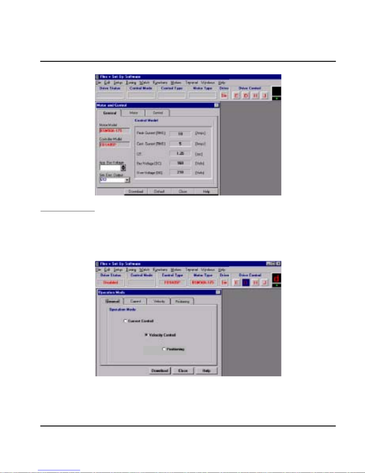
After the motor and control are selected, click the General menu and note that the values are filed in.
Operating Mode Select the operating mode of the control. Choices are:
1. Current Mode
2. Velocity Mode
3. Positioning (15 preset point to point moves)
Click “Download” when finished.
Figure A-5 Operating Mode Selection Screen
MN1276
Manual Tuning A-3
Page 85

Current Parameter
Nominal and peak current values are automatically entered for the motor type.
For manual tuning only, set the control current limit value to a percentage of the
continuous current rating. For example, if your control is rated for 5A continuous
current and you desire to limit the output current to 4A, enter 80%. If you wish to
use the full output power of the control, enter 100%. Click “Download” when
finished.
Figure A-6 Current Parameter Screen
Velocity Parameter Set the velocity parameters of the control:
1. Scale factor - ratio of the input voltage to output RPM.
2. Minimum velocity
3. Time to maximum velocity
Click “Download” when finished.
Figure A-7 Velocity Parameter Screen
A-4 Manual Tuning
MN1276
Page 86

Drift If you know the input offset value of the control, you may enter the value manually.
Otherwise, you may initiate automatic offset tuning and let the control measure
and set this value. Click “Download” when finished.
Figure A-8 Drift Parameter Screen
Manual Tuning The first six steps of the manual tuning process is shown in Figure A-9.
Figure A-9 Select Manual Tuning
1
Select
Tuning
2
Select Manual
Tuning
4
Select Pole
Placement
5
Enter either Inertia
or Inertia Ratio
(the other value is
automatically
entered).
3
Select OK
6
Enter a value
for Bandwidth
7
Click on
Download
If “Pole Placement” method of adjustment is selected, you would enter values for
“inertia” or “inertia ratio”. Enter either one, and the other value will automatically
be entered. This is the easiest and recommended method of adjustment.
If “PI” method of adjustment is selected, you would enter values for GV--gain and
GVI--gain. This is an advanced method of adjustment, and is more difficult.
Both methods of adjustment provide identical results. PI method is described
later in this section.
MN1276
Manual Tuning A-5
Page 87

POLE
PLACEMENT
Pole placement provides a “no--overshoot response” when tuned for the correct
inertia. This is the easiest and recommended method of adjustment.
2
Inertia Click in the “Load” block and enter the value in Kg--cm
2
0to133Kg--cm
.
. The range is from
If the inertia is under--estimated, the system will be stable. If the inertia is
over--estimated, the system will vibrate or oscillate due to too much system gain.
If the load inertia is unknown, estimate low. It is recommended to start with “load
inertia = 0.2”, which represents a stable condition.
If you entered the “inertia ratio”, you should enter a value representing the ratio of
reflected load inertia to motor inertia. The range is from 0 to 100.
Response Move to the “Response” block and place the cursor in the “bandwidth” window,
and click on it.
The “bandwidth” is a measure of the range over which the system can respond. It
is expressed in frequency or Hertz. This parameter controls the “rise time” of the
system. It does not effect overshoot.
It is recommended that bandwidth is increased only if higher dynamic response is
required. Increase the bandwidth and observe (go to plotting of move) the
“velocity” and “command current”, until current reaches maximum value, then back
off to 80%. The range is from 10--200.
The next step, would be to verify that the value you entered, provides for adequate
system response. You can check this out, by having the software move the
equipment and plot the response. Proceed to “Plotting of Move”.
Over--Estimated Under--Estimated
1500
1000
500
Velocity (RPM)
0
--500
Velocity Command / Velocity
Time
Tracking factor
The tracking factor parameter controls the amount of tracking versus overshoot.
The range is 0 to 200. A “tracking factor” of “0” generates no overshoot. A
“tracking factor” of 200 results in a PI equivalent control (i.e. with overshoot).
The next step, would be to verify that the values you entered, provides for
adequate system response. You can check this out, by having the software move
the equipment and plot the response. Proceed to “Plotting of Move”.
Click in the “Tracking” block and enter the desired adjustment value. This
adjustment is used for applications that require improved tracking (or following)
capability, to improve (or reduce) following error.
Figure A -10 Inertia and Load Response Examples
1500
1000
500
Velocity (RPM)
0
-- 5 0 0
Velocity Command / Velocity
Time
1500
1000
500
Velocity (RPM)
-- 5 0 0
Velocity Command / Velocity
Good Response
0
Time
A-6 Manual Tuning
MN1276
Page 88

PI COMPENSA
TION
PI method of adjustment allows adjustment of the acceleration ramp time and
overshoot values. If “PI” Compensation is selected, you would enter values for
GV--gain and GVI--gain. Select PI Compensation instead of Pole Placement on
the menu shown in Figure A-9.
This is an advanced method of adjustment for use by servo engineers. The “pole
placement” method is easier to use for most applications and is recommended.
Figure A -11 PI Compensation Menu
GVI--Gain The “Integral Gain (GVI)” is the “integral gain” of the velocity loop. It controls 1)
the stiffness (the ability to reject load disturbances), and 2) the amount of offset, or
following error, during steady state conditions (velocity command or load does not
change). The adjustable range is from 0 to 32767.
1. Click on the “Integral Gain (GVI)” box and enter a value. You may want
to begin with the default values – click on the “default” button and
answer “yes. To increase stiffness, increase the GVI--gain setting. It
rejects load disturbance and compensates for system friction.
To reduce following error, or offset, during steady state running
conditions, increase the GVI--gain setting. To reduce the overshoot,
reduce the GVI--gain setting.
Note: As you increase the value for GVI, the system will become unstable, i.e.
oscillate. You may hear an audible noise. Decrease the GVI value
immediately. Continue to decrease the value until the noise is no longer
heard, then decrease it another 10%.
2. Next, verify that the value you entered provides adequate system
response. To verify, have the software move the equipment and plot the
response. Proceed to “Plotting of Move”.
MN1276
Manual Tuning A-7
Page 89

GV--Gain This is the “proportional gain” of the velocity loop. It controls the gain of the
velocity loop by adjusting the controls response to the error. The error is the
difference between the commanded and actual velocity. The higher the gain, the
smaller the difference (or error). The adjustable range is from 0 to 32767.
1. Click in the “Proportional Gain (GV)” box. Enter a value for GV. You
may want to begin with the default values – click on the “default” button
and answer “yes”.
Note: The default values may not be best for all applications, it may be too high. If
the system is noisy (displays an audible noise) decrease this value
immediately.
To obtain a faster rise time, increase the GV--gain setting. The ramp up
time (to operating speed) will be faster. As you increase the value for
GV, the system may have very large overshoots and become unstable.
Decrease the GV value immediately. Then decrease it another 10%.
2. Next, verify that the value you entered provides adequate system
response. You can check this out, by having the software move the
equipment and plot the response. Proceed to “Plotting of Move”.
A-8 Manual Tuning
MN1276
Page 90

Plotting of Move
Control Window
At any time after the setup parameters are downloaded to the control, you may
proceed to the plotting routine. Plot allows you to verify that the parameter values
you entered provide adequate system response.
In this section, you will inform the software what move to perform. You will enter
time (for the move), direction (CW or CCW) and speed. It is recommended that
you start with low speeds (i.e. 100 RPM) and short time periods (i.e. 0.5 sec) until
you get a feel for your system.
Enter the parameter values using the Pole Placement menu and click the
“Download” button. Refer to Figure A-9 for details.
Figure A-12 Record & Plot Menu
1.0
0.8
0.6
0.4
0.2
Velocity (RPM)
0
0.04 0.08 0.13 0.17 0.21 0.25 0.29 0.33 0.38 0.42
Graphic Screen
Jog Block
Initiate Move
2 Select 1P variable
Overshoot
Good Response
(Constant Acceleration)
3 Select 2P variable
Time (sec)
1
Click Record
4
Enter
Jog
values
5
Click on CW or CCW
Click on the “Record” button to activate a graphic screen.
Move the cursor to the “plot variable” window (1P and 2P windows = 1
st
and 2
nd
Plot windows) and choose one or two variables which will be drawn on the plot
(such as velocity, velocity command, etc).
Click on “velocity” in the Jog window. Enter a value to run the motor. A low speed
(i.e. 100 RPM) is recommended.
Click on “duration” in the Jog window. Choose a duration time (range is 0.01 to 32
seconds). Recommend that you use a short time period (i.e. 0.5 sec).
Click on either the “CW” or “CCW“ button. This selects the direction of movement
and the software will plot the variables you selected. Observe the performance
plot. If it meets your expectations, you are done. If you wish to alter parameters
and view another plot, repeat the above procedure.
MN1276
Manual Tuning A-9
Page 91

Pulse Follower Applications
Choose T
uning
Select the “Manual tune” method as shown in Figure shown in Figure A-9.
Position Parameters
Click on the “Position Parameters” button. You will see parameters as shown in
Figure A-13. Selecting “None Feedforward” allows you to enter Position Gain.
Select Velocity feedforward allows you to enter Position Gain and Velocity, a
parameter that is proportional to the desired velocity. Increasing this gain,
compensates for damping (brings actual velocity closer to desired velocity). It is
not within the servo loop, so it does not effect stability. The adjustable range is
from 25 to 100%.
Select Acceleration feedforward allows you to enter Position Gain and Velocityand
Acceleration. Acceleration is a parameter that is proportional to the desired
acceleration. Increasing this gain, compensates for inertia (brings desired
acceleration closer to actual acceleration). It is not within the servo loop, so it
does not effect stability. Inertia resists acceleration. The adjustable range is from
25 to 100%.
Initiate Move
To verify that the parameter values are correct, you must cause the system to
move. This would be accomplished by having the “host controller”, or “indexer”, or
“computer” output a string of pulses.
During movement, observe the “Monitor” (7--segment display) on the front panel.
If a “P” is observed on the Monitor display, the drive is within the “in--position” band
which has been set. If a “P” is not observed, then the drive is outside the band, or
window. This would occur, for example, with a high friction system.
Either the gain or feedforward term must be adjusted, or the “in--position” band
must be opened (until a “P” is observed).
Note: To change the “in--position” band or window, you have to choose Setup
(from the “toolbar” at top of the screen). In the box, choose “O
Mode”. You will see choices of “general”, “current”, “velocity”, and “pulse”.
Select “pulse” tab. This will open the window showing the “following error
limits”. You may enter and modify (open) the in--position bands.
(Only used in “pulse follower” applications).
Figure A-13 Position Control Menu
peration
A-10 Manual Tuning
MN1276
Page 92

Appendix B
Command Set
Flex -- ASCII -- Command -- Set
General
Flex controls use the RS232 communication port (optional RS485) as the
Interface. This document describes existing FlexDrive/Flex+Drive ASCII terminal
commands for setup and control of the servo drive.
There are three types of ASCII commands:
1. Parameters. Without parameters, these commands are handled as
queries. To modify the value of a parameter, the value to be set is added
to the command. Some parameters may only be modified under special
drive conditions. Query is not restricted t o special drive conditions.
2. Variables or system constants. System variables are internally updated
in the control, and can not be changed by the user. System constants
are fixed (e.g. by hardware) system properties. Query of variables or
constants is not restricted to special drive conditions.
3. Methods support control of the system. Methods may or may not require
a parameter. Commanding a method to be executed is in some cases
also restricted to special drive conditions. Each command is defined as
a special mnemonic, which is used for query of parameters, variables
and constants as well as for parameter less methods. Modifying a
parameter respectively commanding a parameterized method is done by
simply adding the parameter value to the mnemonic.
Syntax
General structure of the ASCII command
Each ASCII command is structured in principle according to “Mnemonic”
“Delimiter” “Parameter List”. Syntax allows multiple commands in the same string
separated by blank space delimiter. Each command string is terminated by a
carriage return. i.e. generally, a command string looks like:
“Mnemonic1” “Delimiter” “Parameter List1”... “MnemonicN” “Delimiter” “Parameter ListN” [CR]
Up to 80 characters are allowed at the command prompt.
For each correct command the control returns a “>” sign (ASCII 3E hex) as an
acknowledge. If a command is not accepted, the reason for the command revision
is sent instead of the acknowledge.
Mnemonics
The mnemonics are not case sensitive. Most of the ASCII commands are grouped
into functional groups. The Mnemonics of the commands of parameters, variables
and methods of these function groups have a prefix, which indicate the function
and, separated by the dot, the command identifier. The general structure of
Function Group Commands is as follows:
“Functional Group”.“Command Identifier” “Delimiter”“Parameter list” [CR].
e.g.SYS.MOD 1
All prefixed commands are drive parameters. The delimiter between mnemonic
and parameter of these commands is either blank space or equal sign (one of both
is mandatory). To query all parameters and variables of a function group, the
function group prefix followed by dot and asterisk can be used:
“Functional Group”.*
e.g.SYS.*
Command Set B-1MN1276
Page 93

Upon receiving a command, the controller answers by sending the function
parameter and variable list. General purpose commands are not prefixed. These
commands only consist of the command identifier and therefore need the general
structure
“Command Identifier” [“Delimiter”]“Parameter list” [CR]
With the non--prefixed commands, no delimiter is mandatory, but the blank space
can be inserted optional.
Parameters and Units
The parameters used within the ASCII commands are integers of different sizes:
INTEGER:
UNSIGNED INT: 16 bit value ranged 0.. FFFF hex (0..2
LONG: 32 bit value ranged 80000000.. 7FFFFFFF hex ( --2
UNSIGNED LONG: 32 bit value ranged 0.. FFFFFFFF hex ( 0.. +2
16 bit value ranged 8000.. 7FFF hex ( --215.. +215--1 dec. )
16
dec.)
31
31--1
.. +2
dec.)
32--1
dec.)
STRINGS: Strings of ASCII characters (0 .. FF hex).
A string parameter is preceded and terminated with double quote character (')!
Commands, which accept or require more than one parameter, use parameter lists
which are composed of the sequence of parameters necessary, with the delimiters
blank space or comma between.
The number of the parameter can be given as decimal value or as hexadecimal
value. Hexadecimal values are preceded by one or more 0--character (30 hex),
while decimal values are taken as default without indicator.
The ASCII command set description below, also shows the units of the parameters
respectively indicate parameters with no units. For best resolution within the
accepted range, the units of the parameters are not chosen according to SI, but
most of the units used are SI units multiplied with potentials of 10.
In some cases, units are related to system properties and can therefore not be
same for all applications. The following is an example of how to calculate Counts
and Limits, used with positioning and homing:
max. RPM Resolution Counts/rev. Limits
< 1500 216 216 " 229--1
< 6100 214 216 " 229--1
< 6100 212 216 " 229--1
Pulses/rev. Resolution Counts/rev. Limits
1000 4000 64000 225--1
1500 6000 48000 226--1
2000 8000 64000 226--1
2500 10000 40000 227--1
5000 20000 40000 228--1
6000 24000 48000 228--1
The resolution of all (Resolver or Encoder) is between " 213and " 214.
B-2 Command Set MN1276
Resolver
Encoder
Page 94

Start--up with Terminal Communication and Command Examples
1. Select the correct COM port NR. and set the following at your PC:
-- Baud Rate: 9600
-- Protocol (Hardware, Xon/Xoff, None): OFF
-- Data Length: 8 Bit
--Stop Bit: 1
-- Parit y : N O NE
2. Set the control address. The address is set by switch AS1-1 to AS1-4.
To locate a control, type “A” then the control address, e.g. A3 (searches
for a control with address 3). If a drive with address “3” is running and
connected to the PC COM, this drive answers with the prompt sign “>” to
indicate that communication to the drive is established. Additional
command may be sent to the A3 control.
Entering an address command with another address number, will
terminate communication with control A3. If more than one drive is
connected to the PC COM port, typing the address of another drive
connected, will change communication path to this one.
3. Communication is now established and the ASCII commands may be
used.
Note: If more than one drive is connected to the PC port, correct communication
can only be established if all drives have different addresses.
4. Error messages (from the control)
If the syntax and the values of the ASCII command string are correct, the
control accepts the command and answers by sending “<” as
acknowledge. If any error within the transferred command was found,
the control rejects the command by sending a correlated error string.
There are following terminal--reported errors :
-- SYNTAX ERROR: invalid character;
-- EXECUTION ERROR: invalid command;
-- RANGE ERROR: invalid parameter value;
-- INVALID EXE CONTEXT: invalid command or operation mode;
-- control DESIGN FAILURE: invalid control design;
-- INPUT BUFFER OVERFLOW: command line exceeded 80 char.;
-- TOO MANY PARAMETERS: too many parameters;
-- REQ. PARAMETER MISSED: not enough parameters;
MN1276
In case of an error, the event protocol will return a NAK ( negative
acknowledge ) to a user. The error check can only provide a syntax and
range check for each command. Error checking will not check a wrong
parameter value that may degrade system performance.
Command Set B-3
Page 95

General Settings
SYS.INF
O
Queriesfirmwareversionwithnamingand
ASCIIletter
s
X
¡
System Constants
Command Description Range Common Lev I LevII
SYS.POWER Queries dip switch ID, (see DRV.ID) X
SYS.FBACK Queries system feedback
SYS.INFO Queries firmware version with naming and ASCII letters
(SYS.VER)
SYS.LEVEL Queries level version 1:2
SYS.OPT Queries ALTERA option(s)X 0:7 X
SYS.STTS
(COM.ADDR)
(encoder / resolver)as defined by ALTERA
version number as ASCII string
Most Significant--Word of SYS.STTS gives
control address of (LS--Word s. below).
Control Address is set per Dip Switch
¡ Firmware versions RES--1.xx, ENC--1.xx SYS.VER is equal to
0:1 X
X ¡
X ©
(MS-Word of
SYS.STTS)
SYS.INFO , downward versions: answer to SYS.VER is unsigned integer
version number only
© Firmware versions RES--1.xx, ENC--1.xx only (no version)
Basic System Parameters
Motor Parameters (MTR. prefixed)
Command Description Units Range Default E2/ Par. set
MTR.IDX D3S/FlexDrive/Flex+Drive Setup library
defined Motor Index
MTR.IND Motor inductance 0.01 H 1 : 65535 E/P
MTR.INOM Motor nominal current 0.1 A 1 : 65535 E/P
MTR.IPEAK Motor peak 0.1 A 1 : 65535 E/P
MTR.JM Motor Inertia 0.01 Kg-cm
MTR.MPLS Motor number of poles 1 : 65535 E/P
MTR.RES Motor resistance 0.01 Ohm 1 : 65535 E/P
MTR.KT Motor torque constant (torque to RMS
phase current)
MTR.KV Motor bemf constant V/1000RPM 1 : 65535 E/P
MTR.NAME Motor string name in ASCII characters ASCII char E/P
0.001 Nm/A 1 : 65535 E/P
Unsign Int. E/P
2
1 : 65535 E/P
Drive Parameters (typical DRV. prefixed)
Command Description Units Range Default E2/ Par. set
DRV.BUSAPP Application bus voltage V Unsign. Int. E/P
DRV.BUSOV Application bus over voltage V Unsign. Int. E/P
DRV.BUSV Drive Bus voltage V Unsign. Int. E/P
DRV.I2T I2t warning time 0.01 s 100 : 300 E/P
DRV.ID Drive ID (EEPROM value) to be checked
DRV.IDX FlexDrive/Flex+Drive Setup library index Unsign. Int. E/P
DRV.INOM Drive nominal current 0.1 A Unsign. Int. E/P
DRV.IPEAK Drivepeak current 0.1 A Unsign. Int. E/P
against power ID ( dip switch ) in case of
Version Error ( “U” )
B-4 Command Set
Unsign. Int. E/P
MN1276
Page 96

Additional System parameters (mostly SYS.* prefixed)
Velocity Feedback Parameters:
Command Description Units Range Default E2/ Par. set
MTR.RPLS Resolver number of poles -- 1 : 65535 E/P
SYS.ENCRES Queries / updates encoder feedback
resolution for encoder motors (in pulses
per revolution, i.e. before quadrature)
SYS.ENCTBL Queries encoder motor hall table type. -- 0:2 E/P
pulses/rev. 1 : 16384 E/P
Firmware versions RES--1.xx, ENC--1.xx only Encoder Simulation Output Parameter:
Command Description Units Range Default E2/ Par. set
SYS.ENC Encodersimulation resolution. Range de-
pends on maximum velocity (VEL.MXRPM)
Up to 1500 RPM: 512 :4096; above 1500
RPM: 512 only. Downward versions to
80112d1000,(incl.) also provide the decimal values.
Puls/Rev. 512 : 1024
(2048 : 4096)
(500, 1000
1250, 1500)
E/
Software Limit Switches Parameters:
Command Description Units Range Default E2/ Par. set
LIM.CCW Absolute Position of Software Limit Switch
CCW (related to1 Home, activated after
Homing only)
LIM.CW Absolute Position of Software Limit Switch
CW (related to1 Home, activated after
Homing only)
LIM.ON Deactivate / activate Software Limit
Switches (independent from Hardware
Limit Switches)
1 Counts and Limits depend on Resolver and Encoder
resolution
Counts 1 --Limit:Limit 1 0 E/
Counts 1 --Limit:Limit 1 0 E/
-- 0(off)
1 (on)
0 E/
Variables: NONE
Software Limit Switches Methods:
Command Description Parameter Units Range
LIM.LRN Take actual position as software limit for CW respectively
CCW
MN1276
0: CW
1: CCW
-- 0:1
Command Set B-5
Page 97

PLC Parameters:
Command Description Units Range Default E2/ Par. set
PLC.LINE Defines PLC statement :IF [input]=TRUE,
THEN [action] set/started, with sytax
PLC.LINE [num] [action] [input] [num]
[action] -- PLC line number, and string
parameter for PLC action, fixed to line
number:
0 “ENABLE” (PLC enable)
1 “MAO1” (Digital Input MAO1)
2 “MAO2” (Digital Input MAO2)
3 “MAO3” (Digital Input MAO3, if available)
4 “MAO4” (Digital Input MAO4, if available)
5 “RELAY” (
6 “USRERR” (Error “9”)
7 “FRST” (Fault Reset)
8 “DISA” (Disable active, s. 0)
9 “DISP” (Disable active, s. 0)
10 “HOLD” (Hold--status, s. 0)
11“JOG” (JOG function, s. 0)
12 “GEAR”
[input] -- string parameter with enumerated
values:
“FALSE”: Always false, i.e. switched off
“CW”, “CCW”: Hardware or Software
Limit Switches
“MAI1”, “MAI2 ”: Digital Inputs
“MAI3”, “MAI4”: Digital Inputs (if
available)
“DRVOT”,“MTROT”: Drive respectively
motor overtemperature
“I2tWRN”: I
“TRUE”: Always true, i.e. switched ON
“INPOS”, “FEWRN”, “FEFAT”: Flags of
Position Controller in position,
following error warning, following error
limit (s. 0)
BADMOV: Not initialized motion buffer
line commanded (s. 0)
“MOTRDY”, “MOTNRDY”: Positioning
finished respectively in process
2
T--warning (error “7”)
num:0:12
action: s. left
lines:
input: s. left
lines:
PLC disabled,
all lines:
input = false
E/P
Choice of Inputs and Outputs is not completely available in all configurations
Variables: NONE
PLC Methods:
Command Description Parameter Units Range
PLC Enables (“on”) / disables (“off”) / clears and disables (“clr”)
PLC. PLC on and off command is stored in PLC buffer line
0.
B-6 Command Set
“on”, (“off”), “clr”
MN1276
Page 98

OCI Interface Parameters:
Command Description Units Range Default
CAN.BD (The range check is: Invalid execute
context.) It should be: “Range error”
CAN.ID (The range check is: Invalid execute
context.)
Hz 10 : 1000 OK
-- 1 : 127 OK
Significant
E2/ Par. set
Digital Interface Parameters:
Command Description Units Range Default E2/ Par. set
MOT.INCCW Defines digital Input CCW/MAI4 as CCW
(0) or as MAI4 (1) for positioning
MOT.INCW Defines digital Input CW/MAI3 as CW (0)
or as MAI3 for positioning
-- 0:1 0 E/P
-- 0:1 0 E/P
Analog Interface Parameters:
Command Description Units Range Default E2/ Par. set
SYS.RFOFS
(RFOFS)
Query / updates system reference offset of
the analog input, with analog input range
"10V (RFOFS only supports query)
mV --100000 :
100000
0 E/--
Note: Scaling of the analog input command is offered with firmware versions
RES--1.xx, ENC--1.xx. Because scaling parameters are different for current
mode and velocity mode, these parameters are described under 0 (current
command scaling) respectively 0 (velocity command scaling).
MN1276
Command Set B-7
Page 99

System Variables
General Variables:
Command Description Units Range Default E2/ Par. set
DRV.LIFE Drive life time. Hrs Unsign.Word E/-SYS.STTS Queries system status as a double word,
where Word High word is drive address
(set by Dip switches)
Low word: bit array “OR”ed with system
status:
0x0001: Disable SW
0x0002: Disable HW
0x0004: CW
0x0008: CCW
0x0010: Fault exists
0x0020: Warning exits
0x0040: Hold mode
0x0080: Burn in Status
0x0100: Jog Status
0x0200: Enable
0x0400: Jog Non Zero Velocity
0x0800: n/a
0x1000: HW source for Disable HW:
0x2000: PLC active
-- Long Word -- / --
Queries / modifications of Fault Listing Variables:
Command Description Units Range Default E2/ Par. set
FAULT Gets system fault string list, response is
multiple string X1
FLT Gets system fault string list, response is
error numberX1
LOG, LG Gets system fault log list X1 -- X1 -- / -LG Gets system fault log number list X1 -- -- / -WRN Gets system warning list as multiple strings -- -- / -SYS.FAULT Queries system fault as ID of the most
significant fault
SYS.WRN Queries system warnings. The most
important warning will be reported as ID
-- -- / --
-- X1 -- / --
-- -- / --
-- -- / --
X1 Possible Faults
X1 Fault
1 “USER ERROR” PLC user generated error. Displays ’9’.
2 “OVERCURRENT” over current. displays ’3’.
3 “OVERVOLTAGE” 3-- bus over voltage. displays ’1’.
4 “FEEDBACK” resolver/encoder position feedback error. displays ’5’.
5 “POWER_FAIL” power fail. displays ’2’.
6 “BPS” BPS fail. displays ’2’.
7 “OVER_15_VOLTAGE” "15v over voltage. +15v line is more then 17v or --15v line is
8 “UNDER_15_VOLTAGE” "15v under voltage. +15v line is less then 12v or --15v line is
9 “EEPROM_ERROR” N.I
10 “EPROM_ERROR” N.I
11 “RAM_ERROR” RAM integrity error. Displays ’9’.
Display Description
B-8 Command Set
more than --17v. displays ’4’.
less than --12v. displays ’4’.
MN1276
Page 100

X1 Possible Faults -- Continued
X1 Fault
12 “FAULT_RELAY” when fault relay is closed. Displays ’9’.
13 “EAF” N.I
14 “MISSING INT” N.I
15 “POWER_ID” DRV.ID != SYS.POWER. Displays small ’u’.
16 “CW_CCW” Both limit switches are on. Displays ’L’.
17 “DESIGN_FAILURE” Control design fail. Displays small ’c’.
18 “EE_CLEARED” EEPROM header stamp was not detected.
19 “EE_INTEGRITY” EEPROM footer stamp was not detected. Displays big ’A’.
20 “EAF Drive Temp” EAFdrive over temperature error. Displays ’6’.
21 “EAF Motor Temp” EAF motor over temperature error. Displays ’6’.
22 “EAF Drive I2T” EAF drive I2T error. Displays ’6’.
23 “EAF Motor I2T” EAF motor I2T error. Displays ’6’.
Display Description
Displays big ’U’
Methods:
Command Description Parameter Units Range
FRST Resets system faults if allowed. Reset is not allowed, if
error is still pending.
LOGRST Resets system fault log -- -- --
-- -- --
Communication Settings
Parameter:
Command Description Units Range Default E2/ Par. set
ECHO Disable / enable echoing for input
characters
PROMPT Enables / disables terminal prompt -- “ON/OFF “ON” -- / -TALK Enables / Disables terminal error
notification
-- “ON/OFF “ON” -- / --
-- “ON/OFF “ON” -- / --
Variable:
Command Description Units Range Default E2/ Par. set
COM.STTS Queries the most recent communication
handler error
Methods:
Command Description Parameter Units Range
B Opens communication to the drive, c alled by its address
(the addresses a constant, which can be queried by
COM.ADDR or SYS.STTS)
MN1276
-- 0:65535 -- / --
Address -- 0:7
Command Set B-9
 Loading...