

Page 1

FlexDrive
II
/ Flex+Drive
II
Servo Controls
SERVO DRIVE
Installation Manual
10/02 MN1902
Page 2

Page 3

Contents i
MN1902
Contents
1 General Information 1-1.................................
2 Introduction 2-1........................................
2.1 FlexDriveIIfeatures 2-1.....................................
2.2 Receiving and inspection 2-2................................
2.2.1 Identifying the catalog number 2-2....................................
2.3 Units and abbreviations 2-3..................................
3 Basic Installation 3-1....................................
3.1 Introduction 3-1............................................
3.1.1 Power sources 3-1................................................
3.1.2 Hardware requirements 3-1.........................................
3.1.3 RS485 / RS422 systems 3-2........................................
3.1.4 Tools and miscellaneous hardware 3-2................................
3.1.5 Other information needed for installation 3-3...........................
3.2 Mechanical installation and location requirements 3-4...........
3.2.1 Mounting the FlexDrive
II
3-5.........................................
3.2.2 Dimensions 3-6...................................................
3.3 Connector locations 3-7.....................................
3.4 Power connections 3-8......................................
3.4.1 Single-phase connection to package sizes A, B, C, D 3-9................
3.4.2 Three-phase connection to package sizes E, G, H 3-10...................
3.4.3 Input power conditioning 3-11.........................................
3.4.4 Power disconnect and protection devices 3-11..........................
3.4.5 Power supply filters 3-12.............................................
3.4.6 Wire sizes and protection device ratings 3-13...........................
3.4.7 External customer supplied 24V control supply 3-14......................
3.5 Motor connections 3-15......................................
3.5.1 Motor circuit contactors 3-16.........................................
3.5.2 Motor power cable pin configuration - Baldor BSM rotary motors 3-16.......
3.5.3 Motor cable pin configuration - Baldor linear motors 3-17..................
3.5.4 Thermal switch connection 3-18.......................................
3.5.5 Motor brake connection 3-19.........................................
3.6 Regeneration resistor (Dynamic Brake resistor) 3-20.............
3.6.1 Controlling regeneration 3-20.........................................
3.7 Feedback connections 3-21...................................
3.7.1 Resolver option - X8 3-22............................................
3.7.2 Encoder option - X8 3-24............................................
3.7.3 EnDat (absolute encoder) option - X8 3-27..............................
Page 4

ii Contents
MN1902
3.8 Drive enable - X3 3-29.......................................
3.8.1 Drive enable - X3 3-29..............................................
3.8.2 Drive enable - SW1 DIP switch 3-30...................................
3.8.3 Drive enable command 3-30..........................................
3.9 DIP switches - SW1 3-31.....................................
3.9.1 Switches 1-4 3-31..................................................
3.9.2 Switch 5 - Hold 3-32................................................
3.9.3 Switch 6 - RS485 terminator 3-32.....................................
3.9.4 Switch 7 - Offset tuning 3-32.........................................
3.9.5 Switch 8 - Enable 3-32..............................................
3.9.6 Switches 9 and 10 - RS232/RS485 select 3-33..........................
3.9.7 Factory settings 3-33................................................
3.9.8 Preventing a program running at startup 3-34...........................
4 Input / Output 4-1......................................
4.1 Introduction 4-1............................................
4.2 Analog I/O 4-1.............................................
4.2.1 Analog input - X3 (command) 4-2....................................
4.2.2 Relay output - X3 4-4..............................................
4.3 Digital I/O 4-5..............................................
4.3.1 Digital inputs - X3 4-6..............................................
4.3.2 CREF and digital inputs 4-7.........................................
4.3.3 Special functions on DIN4 and DIN5 - pulse and direction inputs 4-7.......
4.3.4 Special functions on DIN4 and DIN5 - fast inputs 4-8....................
4.3.5 Digital outputs - X3 4-9.............................................
4.4 Other I/O 4-10..............................................
4.4.1 Encoder output - X7 4-10............................................
4.4.2 Master (auxiliary) encoder input - X9 4-12..............................
4.4.3 Serial port - X6 4-14.................................................
4.4.4 Using RS232 cable 4-15.............................................
4.4.5 Multidrop using RS485 / RS422 cable 4-16.............................
4.4.6 Connecting Baldor HMI Operator Panels 4-17...........................
4.5 Connection summary - minimum system wiring 4-18.............
4.6 Option connectors 4-19......................................
5 Operation 5-1..........................................
5.1 Introduction 5-1............................................
5.1.1 Connecting the FlexDriveIIto the PC 5-1..............................
5.1.2 Installing the software 5-1...........................................
5.1.3 Starting the FlexDrive
II
5-2..........................................
5.1.4 Preliminary checks 5-2.............................................
5.1.5 Power on checks 5-2...............................................
5.1.6 Offset tuning 5-3..................................................
Page 5

Contents iii
MN1902
5.2 WorkBench v5 5-4..........................................
5.2.1 Help file 5-4......................................................
5.2.2 Starting WorkBench v5 5-5..........................................
5.2.3 Commissioning Wizard 5-7..........................................
5.2.4 Using the Commissioning Wizard 5-7.................................
5.2.5 Completing the Commissioning Wizard 5-7............................
5.3 Further configuration 5-8....................................
5.3.1 Fine-tuning tool 5-8................................................
5.3.2 Parameters tool 5-10................................................
5.3.3 Digital I/O tool 5-11.................................................
5.3.4 Other tools and windows 5-11........................................
6 Troubleshooting 6-1....................................
6.1 Introduction 6-1............................................
6.1.1 Problem diagnosis 6-1..............................................
6.1.2 SupportMet feature 6-1............................................
6.1.3 Power-cycling the FlexDrive
II
6-1....................................
6.2 FlexDriveIIindicators 6-2....................................
6.2.1 Status display 6-2.................................................
6.2.2 DB On (Regeneration) LED 6-5......................................
6.2.3 Communication 6-5................................................
6.2.4 Power on 6-6.....................................................
6.2.5 Tuning 6-6........................................................
6.2.6 Status display shows a digit or ‘E.’ 6-6................................
7 Specifications 7-1......................................
7.1 Introduction 7-1............................................
7.1.1 AC input power and motor output - single-phase models 7-2..............
7.1.2 AC input power and motor output - 230V three-phase models 7-3..........
7.1.3 AC input power and motor output - 230-460V three-phase models 7-4......
7.1.4 Customer supplied 24VDC supply input 7-4............................
7.1.5 Regeneration 7-5..................................................
7.1.6 Analog input (X3) 7-6...............................................
7.1.7 Digital inputs (X3) 7-7..............................................
7.1.8 Digital outputs (X3) 7-7.............................................
7.1.9 Relay output (X3) 7-8..............................................
7.1.10 Serial RS232 interface (X6) 7-8......................................
7.1.11 Serial RS485 interface (X6) 7-8......................................
7.1.12 Encoder output (simulated) (X7) 7-8..................................
7.1.13 Resolver feedback option (X8) 7-9...................................
7.1.14 Encoder feedback option (X8) 7-9....................................
7.1.15 EnDat (absolute encoder) feedback option (X8) 7-9.....................
7.1.16 Master (auxiliary) encoder input (X9) 7-10..............................
7.1.17 Pulse and direction input (X9) 7-10....................................
7.1.18 Environmental 7-1 1.................................................
Page 6

iv Contents
MN1902
Appendices
A Accessories A-1........................................
A.1 Introduction A-1............................................
A.1.1 Factory fitted options A-1...........................................
A.1.2 Motor power cables A-2.............................................
A.1.3 Motor power cable part numbers A-2..................................
A.1.4 Feedback cables A-3...............................................
A.1.5 Feedback cable part numbers A-4....................................
A.1.6 EMC filters A-5....................................................
A.1.7 Regeneration resistors A-7..........................................
B Control System B-1.....................................
B.1 Introduction B-1............................................
B.1.1 Current (Torque) control B-2.........................................
B.1.2 Velocity (Speed) control B-3.........................................
B.1.3 Position control (Pulse and Direction) B-4..............................
B.1.4 Position control B-5................................................
B.2 Control system operation B-6................................
B.2.1 Position controller B-6..............................................
B.2.2 Speed controller B-7...............................................
B.2.3 Torque controller and feedback B-8...................................
C CE Guidelines C-1......................................
C.1 Outline C-1................................................
C.1.1 EMC Conformity and CE marking C-1.................................
C.1.2 Use of CE compliant components C-2.................................
C.1.3 EMC wiring technique C-2...........................................
C.1.4 EMC installation suggestions C-3.....................................
C.1.5 Wiring of shielded (screened) cables C-4..............................
Page 7

General Information 1-1MN1902
LT0160A02 Copyright Baldor (c) 2002. All rights reserved.
This manual is copyrighted and all rights are reserved. This document or attached software may not,
in whole or in part, be copied or reproduced in any form without the prior written consent of Baldor.
Baldor makes no representations or warranties with respect to the contents hereof and specifically
disclaims any implied warranties of fitness for any particular purpose. The information in this
document is subject to change without notice. Baldor assumes no responsibility for any errors that
may appear in this document.
Mintt is a registered trademark of Baldor.
Windows 95, Windows 98, Windows ME, Windows NT, Windows XP and Windows 2000 are
registered trademarks of the Microsoft Corporation. UL and cUL are registered trademarks of
Underwriters Laboratories. EnDat is a registered trademark of Heidenhain Corporation.
Limited Warranty
For a period of two (2) years from the date of original purchase, Baldor will repair or replace without
charge controls and accessories that our examination proves to be defective in material or
workmanship. This warranty is valid if the unit has not been tampered with by unauthorized persons,
misused, abused, or improperly installed and has been used in accordance with the instructions and/or
ratings supplied. This warranty is in lieu of any other warranty or guarantee expressed or implied.
Baldor shall not be held responsible for any expense (including installation and removal),
inconvenience, or consequential damage, including injury to any person or property caused by items of
our manufacture or sale. (Some countries and U.S. states do not allow exclusion or limitation of
incidental or consequential damages, so the above exclusion may not apply.) In any event, Baldor’s
total liability, under all circumstances, shall not exceed the full purchase price of the control. Claims for
purchase price refunds, repairs, or replacements must be referred to Baldor with all pertinent data as
to the defect, the date purchased, the task performed by the control, and the problem encountered. No
liability is assumed for expendable items such as fuses. Goods may be returned only with written
notification including a Baldor Return Authorization Number and any return shipments must be prepaid.
1 General Information
1
Page 8

1-2 General Information MN1902
Product notice
Only qualified personnel should attempt the start-up procedure or troubleshoot this equipment.
This equipment may be connected to other machines that have rotating parts or parts that are
controlled by this equipment. Improper use can cause serious or fatal injury. Only qualified personnel
should attempt to start-up, program or troubleshoot this equipment.
Safety Notice
Intended use: These drives are intended for use in stationary ground based applications in industrial
power installations according to the standards EN60204 and VDE0160. They are designed for
machine applications that require variable speed controlled three-phase brushless AC motors. These
drives are not intended for use in applications such as:
H Home appliances
H Medical instrumentation
H Mobile vehicles
H Ships
H Airplanes.
Unless otherwise specified, this drive is intended for installation in a suitable enclosure. The enclosure
must protect the drive from exposure to excessive or corrosive moisture, dust and dirt or abnormal
ambient temperatures. The exact operating specifications are found in section 7 of this manual. The
installation, connection and control of drives is a skilled operation, disassembly or repair must not be
attempted. In the event that a drive fails to operate correctly, contact the place of purchase for return
instructions.
Precautions
WARNING: Do not touch any circuit board, power device or electrical connection before you
first ensure that no high voltage is present at this equipment or other equipment to
which it is connected. Electrical shock can cause serious or fatal injury. Only
qualified personnel should attempt to start-up, program or troubleshoot this
equipment.
WARNING: Be sure the system is properly earthed/grounded before applying power. Do not
apply AC power before you ensure that earths/grounds are connected. Electrical
shock can cause serious or fatal injury.
WARNING: Be sure that you are completely familiar with the safe operation and programming
of this equipment. This equipment may be connected to other machines that have
rotating parts or parts that are controlled by this equipment. Improper use can
cause serious or fatal injury. Only qualified personnel should attempt to program,
start-up or troubleshoot this equipment.
Page 9
General Information 1-3MN1902
WARNING: Be sure all wiring complies with the National Electrical Code and all regional and
local codes. Improper wiring may result in unsafe conditions.
WARNING: The stop input to this equipment should not be used as the single means of
achieving a safety critical stop. Drive disable, motor disconnect, motor brake and
other means should be used as appropriate. Only qualified personnel should
attempt to program, start-up or troubleshoot this equipment.
WARNING: Improper operation or programming of the drive may cause violent motion of the
motor and driven equipment. Be certain that unexpected motor movement will not
cause injury to personnel or damage to equipment. Peak torque of several times
the rated motor torque can occur during control failure.
WARNING: The motor circuit might have high voltages present whenever AC power is
applied, even when the motor is not moving. Electrical shock can cause serious or
fatal injury.
WARNING: If a motor is driven mechanically, it might generate hazardous voltages that are
conducted to its power terminals. The enclosure must be earthed/grounded to
prevent possible shock hazard.
WARNING: When operating a rotary motor with no load coupled to its shaft, remove the shaft
key to prevent it flying out when the shaft rotates.
WARNING: A regeneration resistor may generate enough heat to ignite combustible materials.
To avoid fire hazard, keep all combustible materials and flammable vapors away
from the brake resistors.
CAUTION: To prevent equipment damage, be certain that the input power has correctly sized
protective devices installed.
CAUTION: To prevent equipment damage, be certain that input and output signals are
powered and referenced correctly.
CAUTION: To ensure reliable performance of this equipment be certain that all signals to/from
the drive are shielded correctly.
CAUTION: Suitable for use on a circuit capable of delivering not more than the RMS
symmetrical short circuit amperes listed here at rated voltage.
Horsepower
RMS Symmetrical Amperes
1-50 5,000
CAUTION: Avoid locating the drive immediately above or beside heat generating equipment,
or directly below water or steam pipes.
Page 10

1-4 General Information MN1902
CAUTION: Avoid locating the drive in the vicinity of corrosive substances or vapors, metal
particles and dust.
CAUTION: Do not connect AC power to the drive terminals U, V and W. Connecting AC
power to these terminals may result in damage to the drive.
CAUTION: Baldor does not recommend using “Grounded Leg Delta” transformer power leads
that may create earth/ground loops and degrade system performance. Instead,
we recommend using a four wire Wye.
CAUTION: Drives are intended to be connected to a permanent main power source, not a
portable power source. Suitable fusing and circuit protection devices are required.
CAUTION: The safe integration of the drive into a machine system is the responsibility of the
machine designer. Be sure to comply with the local safety requirements at the
place where the machine is to be used. In Europe these are the Machinery
Directive, the ElectroMagnetic Compatibility Directive and the Low V oltage
Directive. In the United States this is the National Electrical code and local codes.
CAUTION: Drives must be installed inside an electrical cabinet that provides environmental
control and protection. Installation information for the drive is provided in this
manual. Motors and controlling devices that connect to the drive should have
specifications compatible to the drive.
CAUTION: Violent jamming (stopping) of the motor during operation may damage the motor
and drive.
CAUTION: Do not tin (solder) exposed wires. Solder contracts over time and may cause
loose connections. Use crimp connections where possible.
CAUTION: Electrical components can be damaged by static electricity. Use ESD
(electro-static discharge) procedures when handling this drive.
CAUTION: Ensure that resolver or encoder wires are properly connected. Incorrect
installation may result in improper movement.
CAUTION: The threaded holes in the top and bottom of the enclosure are for cable clamps.
Be sure to use a M4 bolt no longer than 12mm in length. Longer bolts might
short-circuit the electrical components inside the drive.
CAUTION: Removing the cover will invalidate UL certification.
Page 11

Introduction 2-1MN1902
2.1 FlexDriveIIfeatures
Throughout this manual, both the FlexDriveIIand the Flex+DriveIIwill be referred to simply as
FlexDrive
II
. Where there is a difference in specification it will be clearly marked.
The FlexDrive
II
is a versatile compact control, providing a flexible and powerful solution for
single axis rotary systems. Standard features include:
H Single axis AC brushless drive
H Wide range of models with continuous current ratings from 2.5A to 27.5A
H Direct connection to 115V AC or 230VAC single-phase or 230-460VAC three-phase
supplies (model dependent)
H Resolver or encoder feedback
H Velocity and current control, with pulse and direction input for position control
H Auto-tuning wizard (including position loop) and software oscilloscope facilities
H 8 optically isolated digital inputs
H 3 optically isolated digital outputs
H 1 general-purpose analog input (can be used as a speed or torque command reference)
H 1 control relay
H Selectable RS232 or RS485 communications
Flex+Drive
II
only:
H Integrated motion controller for rotary and linear positioning systems
H Programmable in Mint
H Up to 16 programmable preset moves (expandable to 256 with factory-fitted CAN and I/O
option)
H Position control using preset moves, software gearing and point to point moves
H Flash memory for program storage (64k).
H Motion controller for rotary and linear positioning systems
Factory-fitted options expand the I/O capabilities of the FlexDrive
II
and provide CANopen,
DeviceNet or Profibus connectivity. See Appendix A for details about options. FlexDrive
II
will
operate with a large number of brushless servo motors - for information on selecting Baldor
servo motors, please see the sales brochure BR1202 (BR1800 for linear motors) available
from your local Baldor representative.
This manual is intended to guide you through the installation of FlexDrive
II
. The sections
should be read in sequence.
The Basic Installation section describes the mechanical installation of the FlexDrive
II
,the
power supply connections and motor connections. The other sections require knowledge of
the low level input/output requirements of the installation and an understanding of computer
software installation. If you are not qualified in these areas you should seek assistance before
proceeding.
2 Introduction
2
Page 12

2-2 Introduction MN1902
2.2 Receiving and inspection
When you receive your FlexDriveII, there are several things you should do immediately:
1. Check the condition of the shipping container and report any damage immediately to the
carrier that delivered your FlexDrive
II
.
2. Remove the FlexDrive
II
from the shipping container and remove all packing material. The
container and packing materials may be retained for future shipment.
3. Verify that the catalog number of the FlexDrive
II
you received is the same as the catalog
number listed on your purchase order. The catalog number is described in the next section.
4. Inspect the FlexDrive
II
for external damage during shipment and report any damage to the
carrier that delivered your FlexDrive
II
.
5. If FlexDrive
II
is to be stored for several weeks before use, be sure that it is stored in a location
that conforms to the storage humidity and temperature specifications shown in section 7.1.18.
2.2.1 Identifying the catalog number
The FlexDriveIIis available with different current ratings and package sizes. The catalog
number is marked on the front of the unit, just below the Baldor logo. It is a good idea to look
for the catalog number (sometimes shown as ID/No: ) and write it in the space provided here:
Catalog number:
F_H______________-________
Installed at: ________________________
Date: ______
A description of a catalog number is shown here, using the example FDH1A05TB-RC23:
Meaning Alternatives
FDH FlexDriveIIfamily FPH=Flex+Drive
II
1 Requires an AC supply voltage of 115 Volts, 1Φ
2=230V (1Φ or 3Φ);
4=230V-460V (3Φ)
A05 Continuous current rating of 5.0A
A02=2.5A; A07=7.5A; A15=15A;
A20=20A; A27=27.5A
T Built in AC power supply -
B
Dynamic Brake with a built in transistor and
resistor (available on 2.5A and 5A models only)
R= Requires external braking
resistor
R Feedback option is a resolver
E=Encoder;
D=EnDat (absolute encoder)
C Option fitted: 1 CAN channel
B=CAN & Auxiliary I/O
(Flex+Drive
II
only); D=DeviceNet;
P=Profibus DP;
N=No options specified
2 Serial port type is combined RS232 / RS485 -
3
Customer’s own 24VDC supply is required to
power the internal FlexDrive
II
logic
0= Internally generated 24VDC
supply*
* An external 24VDC supply will always be required to operate the enable input, digital inputs
and digital outputs on connector X3 . See sections 4.3.1 to 4.3.5.
Page 13

Introduction 2-3MN1902
2.3 Units and abbreviations
The following units and abbreviations are used in this manual:
V Volt (also VAC and VDC)...............
WWatt..............
A Ampere...............
Ω Ohm...............
µF microfarad..............
pF picofarad..............
mH millihenry.............
Φ phase...............
ms millisecond..............
µs microsecond..............
ns nanosecond..............
Kbaud kilobaud (the same as Kbit/s in most applications)...........
MB megabytes.............
CDROM Compact Disc Read Only Memory.........
CTRL+E on the PC keyboard, press Ctrl then E at the same time..........
mm millimeter.............
m meter...............
in inch...............
ft feet...............
lb-in pound-inch (torque).............
Nm Newton-meter (torque).............
ADC Analog to Digital Converter............
DAC Digital to Analog Converter............
AWG American Wire Gauge............
(NC) Not Connected............
Page 14

2-4 Introduction MN1902
Page 15

Basic Installation 3-1MN1902
3.1 Introduction
You should read all the sections in Basic Installation to ensure safe installation.
This section describes the mechanical and electrical installation of the FlexDrive
II
in the
following stages:
H Location considerations
H Mounting the FlexDrive
II
H Connecting the AC power supply
H Connecting the optional customer supplied 24VDC control supply
H Connecting the motor
H Installing a regeneration resistor (Dynamic Brake resistor)
H Connecting the feedback device
H Connecting the drive enable input.
These stages should be read and followed in sequence.
3.1.1 Power sources
An AC power source (IEC1010 over-voltage category III or less) in the installation area is
required. This will need to be single or three-phase depending upon the type of FlexDrive
II
.
An AC power filter is required to comply with the CE directive for which the FlexDrive
II
was
tested (see section 3.4.5).
If the FlexDrive
II
requires an external (customer supplied) 24VDC logic supply then this must
be a regulated power supply with a continuous current supply capability of 1.75A (4A power on
surge). A 24V filter may be required to comply with the CE directive for which the FlexDrive
II
was tested (see section 3.4.5).
3.1.2 Hardware requirements
The components you will need to complete the basic installation are:
H The motor that will be connected to the FlexDrive
II
H A motor power cable
H A resolver or encoder feedback cable (and Hall cable for linear motors)
H With some applications there may be a requirement for a regeneration resistor (Dynamic
Brake).
Note: Without the regeneration resistor, the drive may produce an overvoltage fault. All
FlexDrive
II
models have overvoltage sensing circuitry, but only 2.5A and 5A
models (catalog numbers FDHxxxxxB-xxxx and FPHxxxxxB-xxxx) have an
internal regeneration resistor. For 7.5A, 15A, 20A and 27.5A models a
regeneration resistor must be purchased separately if required. See Appendix A.
3 Basic Installation
3
Page 16

3-2 Basic Installation MN1902
H A serial cable.
Note: The serial connector on the FlexDrive
II
(connector X6) can be configured as either
RS232 or RS485 / RS422. Pin 9 is used to carry +8V for powering some Baldor
keypad peripherals. Ensure that pin 9 is not connected to earth/ground or to
equipment that could be damaged by the +8V supply. See sections 4.4.3 and
4.4.4. A suitable cable is available from Baldor, catalog number CBL001-501.
H A PC (with one free COM port) with the following specification:
Minimum specification Recommended specification
Processor Intel Pentium 133MHz Intel Pentium 200MHz or faster
RAM 32MB 64MB
Hard disk space 40MB 60MB
CD-ROM ACD-ROMdrive
Screen 800 x 600, 256 colors 1024 x 768, 256 colors
Mouse A mouse or similar pointing device
Operating system Windows 95, Windows 98, Windows ME,
Windows NT, Windows XP or Windows 2000
3.1.3 RS485 / RS422 systems
If you will be using RS485 / RS422 and your PC does not have an RS485 / RS422 connector,
an RS232 to 4-wire RS485 / RS422 converter will be required. These commercially available
devices convert the signals from the RS232/RS485 port (connector X6) to the signals
necessary for RS485 / RS422 communications. Special care must be taken with the pin
assignment on all RS485 / RS422 devices, as this can differ between products. Connectors
might need to be rewired to provide the correct pin assignment. The FlexDrive
II
pin
assignment is shown in section 4.4.3.
Note: If this is the first time you are installing a FlexDriveIIthen it is strongly
recommended that you use RS232 to get started and try RS485 later. This will
avoid any potential problems involving the RS232-RS485 converter. Selection of
RS232 or RS485 is controlled using DIP switch 10 - see section 3.9.6.
3.1.4 Tools and miscellaneous hardware
H Your PC operating system user manual might be useful if you are not familiar with
Windows
H A small screwdriver (supplied) with a blade width less than 3mm (1/10 in)
H M5 screws or bolts for mounting the FlexDrive
II
H Crimping tool.
A connector kit is supplied with your FlexDrive
II
. This contains a number of useful connectors
and a screwdriver for tightening the connections.
Page 17

Basic Installation 3-3MN1902
3.1.5 Other information needed for installation
This information is useful (but not essential) to complete the installation:
H The data sheet or manual provided with your motor, describing the wiring information of
the motor cables/connectors
H Knowledge of which digital inputs/outputs will be ‘Active Low’, ‘Active High’ or edge
triggered.
Page 18

3-4 Basic Installation MN1902
3.2 Mech an ical installation and location requirements
It is essential that you read and understand this section before beginning the
installation
.
CAUTION: To prevent equipment damage, be certain that the input power has
correctly rated protective devices installed.
CAUTION: To prevent equipment damage, be certain that input and output signals
are powered and referenced correctly.
CAUTION: To ensure reliable performance of this equipment be certain that all
signals to/from the FlexDrive
II
are shielded correctly.
CAUTION: Avoid locating the FlexDriveIIimmediately above or beside heat
generating equipment, or directly below water steam pipes.
CAUTION: Avoid locating the FlexDriveIIin the vicinity of corrosive substances or
vapors, metal particles and dust.
The safe operation of this equipment depends upon its use in the appropriate environment.
The following points must be considered:
H The FlexDrive
II
must be installed indoors, permanently fixed and located so that it can
only be accessed by service personnel using tools.
H The maximum suggested operating altitude is 1000m (3300ft).
Above 1000m (3300ft) de-rate output current 1.1% per 100m (330ft).
H The FlexDrive
II
must operate in an ambient temperature of 0°C to 40°C (32°F to 104°F).
De-rate output current 2.5% per 1°C (1.8°F) from 40°C (104°F) to 50°C (122°F) maximum.
H The FlexDrive
II
must operate in relative humidity levels of less than 90% for temperatures
up to 31°C (87°F) decreasing linearly to 50% relative humidity at 40°C (104°F)
(non-condensing).
H The FlexDriveIImust be installed where the pollution degree according to IEC664 shall not
exceed 2.
H The external customer supplied 24VDC for the logic supply must be installed so that the
24VDC supplied to the unit is isolated from the AC supply using double or reinforced
insulation.
H The inputs and outputs of the control circuit must be limited to Safety Extra Low Voltage
circuits.
H Both the AC supply and the external 24VDC supply must be fused.
H The atmosphere must not contain flammable gases or vapors.
H There must not be abnormal levels of nuclear radiation or X-rays.
H The FlexDrive
II
must be secured by the slots in the flange, with the protective
earth/ground stud bonded to a safety earth/ground by either a 25A conductor or a
conductor of three times the peak current rating - whichever is the greater.
Page 19

Basic Installation 3-5MN1902
H For effective cooling and maintenance, the FlexDriveIIshould be mounted on a smooth,
non-flammable vertical surface. The power handling capability is affected by the
temperature of the left side of the unit.
H At least 50mm (2 in) top and bottom clearance of the FlexDriveIImust be provided for
airflow.
H If multiple FlexDrive
II
are being mounted side by side there must be 13mm (0.5 in)
between them. The FlexDrive
II
nearest the side of the cabinet / enclosure must be
separated from it by at least 13mm (0.5 in).
H To comply with CE directive 89/336/EEC an appropriate AC filter must be installed. The
external customer supplied 24VDC logic supply might also require a 24V filter. See section
3.4.7.
H The threaded holes in the top and bottom of the enclosure are for cable clamps. The holes
are threaded for M4 bolts no longer than 12mm (0.47 in) in length. Longer bolts may short
circuit the electrical components inside the FlexDrive
II
.
H Each D-type connector on the front panel of the FlexDrive
II
is secured using two
hexagonal jack screws (sometimes known as “screwlocks”). If a jack screw is removed
accidentally or lost it must be replaced with an identical jack screw with an external male
threaded section of 5mm (0.2 in). Jack screws with longer threads could damage or short
circuit internal components.
3.2.1 Mounting the FlexDrive
II
Ensure you have read and understood the Mechanical installation and location requirements in
section 3.2. Mount your FlexDrive
II
on its rear side, the side opposite to the front panel.
The FlexDrive
II
must be mounted upright to ensure adequate cooling (you can check this by
ensuring that the Hazardous Voltages warning information is clearly readable to you).
M5 bolts or screws should be used to mount the FlexDrive
II
.
There are seven different package sizes depending on the specification of the FlexDrive
II
:
AC power
Current Factory fitted option Package size
Single-phase 2A without option A
with option B
5A without option C
with option D
7.5A without option D
with option D
230V
Three-phase
15A with or without option E
230-460V
2.5A, 5A, 7.5A with or without option G
Three-phase
15A, 20A, 27.5A with or without option H
Detailed dimensions for each package are shown in section 3.2.2.
Page 20
3-6 Basic Installation MN1902
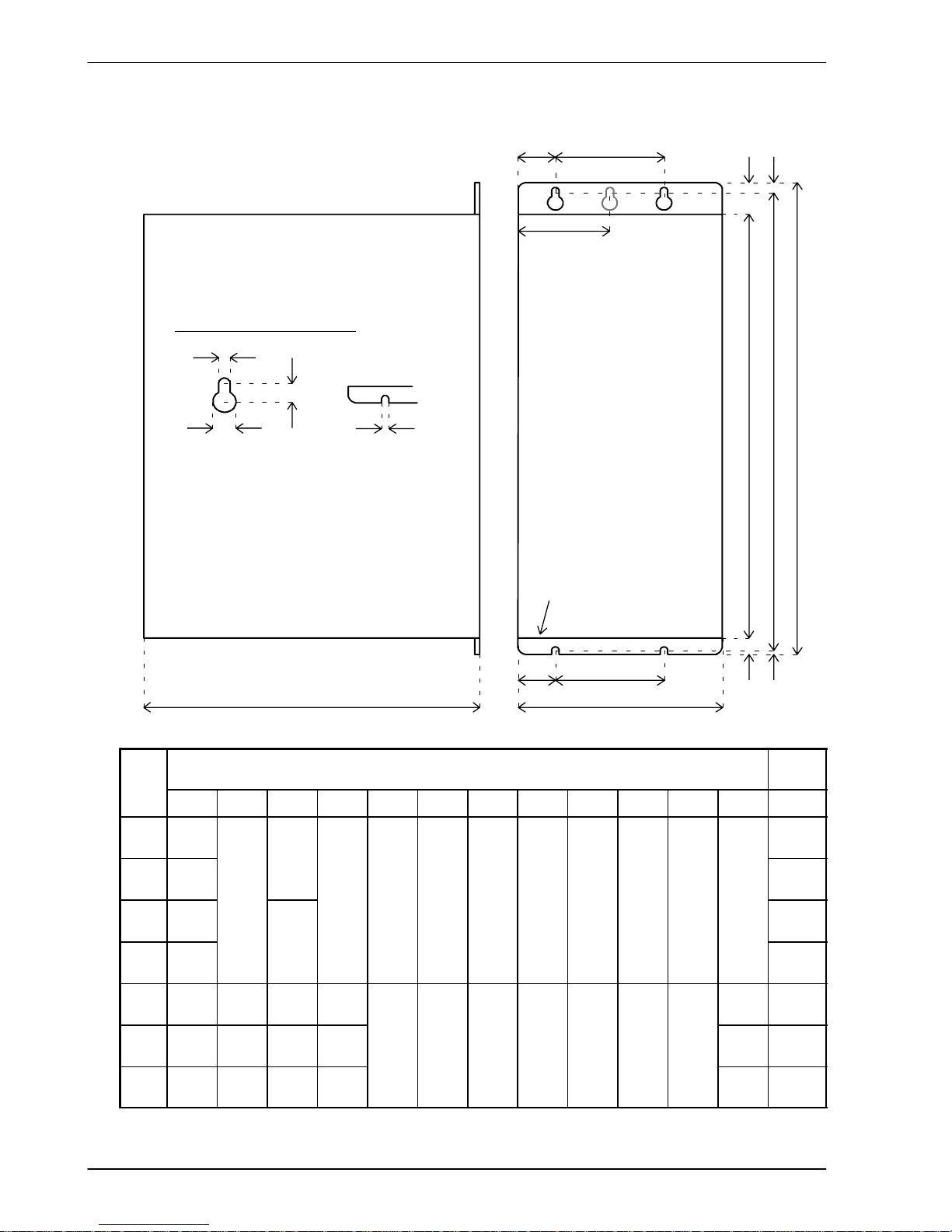
3.2.2 Dimensions
H
1
H
2
H
W
D
W
2
W
1
W
3
Package size
H only.
W
4
Package sizes E, G & H only:
W4=9.5mm.
All other sizes:
W4=W
2
H3H
4
65mm
FRONT PANEL
H5H
6
Mounting keyhole and slot detail
A
B
C
A
A 5mm (package sizes E, G and H: 6.5mm)
B 10mm (package sizes E, G and H: 12mm)
C 9mm (package sizes E, G and H: 10mm)
Dimensions
mm / inches
Weight
Case W W
1
W
2
W
3
H H
1
H
2
H
3
H
4
H
5
H
6
D kg / lb
A 67.5
2.66
15
1.25
2.76
B 84
3.31
40
1
5
0.59
40 173 195.5 205 23.5 6.5 8.5 3 152
1.55
3.42
C 92.5
3.64
4
0
1.57
23
4
0
1.57
173
6.81
195.5
7.70
205
8.07
2
3.5
0.93
6.5
0.26
8.5
0.3330.12
152
6.00
2.1
4.63
D 109
4.29
2
3
0.91
2.3
5.07
E 55
2.17361.42
27.5
1.08
- 263.5
10.37
3.3
7.28
G 65
2.56461.81
32.5
1.28
-
357
14.06
384
15.12
400
15.75
26.5
1.0480.31
16.5
0.6580.31
262
10.31
4.9
10.8
H 130
5.12
111
4.37
27.5
1.08752.95
328
12.91
9.05
19.95
Figure 1 - Package dimensions
Page 21
Basic Installation 3-7MN1902
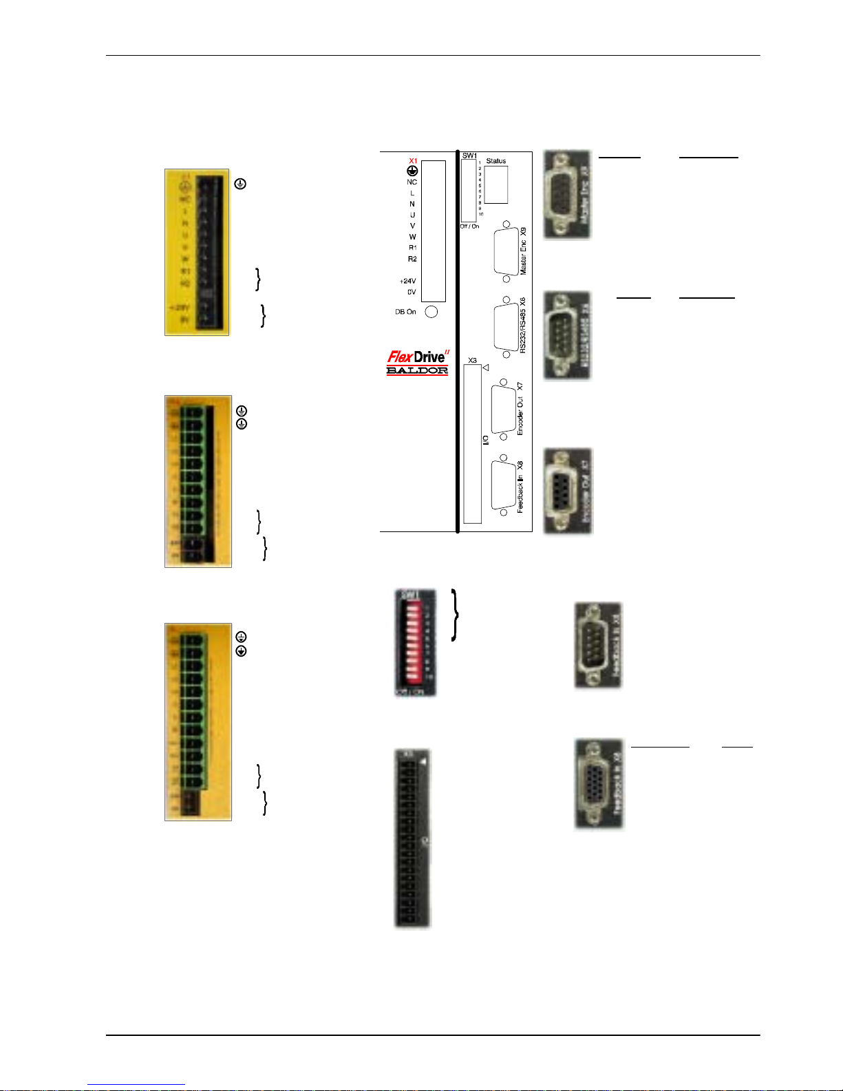
3.3 Conn ecto r locations
1 AIN0+ (Command+)
2 AIN0- (Command-)
3AGND
4 Relay+
5 Relay6UserV+
7 CREF
8CGND
9 Drive Enable
10 DIN0
11 DIN1
12 DIN2
13 DIN3
14 DIN4 (Pulse)
15 DIN5 (Direction)
16 DIN6
17 DIN7
18 DOUT0
19 DOUT1
20 DOUT2
1 CHA+
2 CHB+
3 CHZ+
4 (NC)
5DGND
6 CHA7 CHB8 CHZ9 (NC)
Encoder Pulse & Dir.
1 CHA+ Pulse+
2 CHB+ Dir.+
3 CHZ+ (NC)
4 (NC) (NC)
5DGND (NC)
6 CHA- Pulse GND
7 CHB- Dir. GND
8 CHZ- (NC)
9+5V (NC)
RS232 RS485/422
1 (NC) (NC)
2RXD RX3TXD TX4 (NC) (NC)
5 0V GND 0V DGND
6 (NC) (NC)
7 RTS TX+
8CTS RX+
9 (NC - see section 4.4.3)
1REF+
2COS+
3SIN+
4 (NC)
5AGND
6REF7COS8SIN9 Chassis
1 Node
2 number
3 selection
4
5 (Reserved)
6Hold
7 Offset tuning
8 Enable
9 (Reserved)
10 RS232/RS485
X3 General I/O
X6 RS232/RS485
X7 Encoder Out
X8 Feedback In
Resolver option
Encoder options
X1 / X1A Power
Single-phase models
Three-phase models, 230-460V
Earth
NC (NC)
LACLine
N AC Neutral
U Motor U
V Motor V
W Motor W
R1 Regen Resistor
R2 (Dynamic Brake)
- (NC)
+24V Customer
0V supplied 24V
(FDHxxxxxx-xxx3/
FPHxxxxxx-xxx3)
Options:
If there are other connectors on the
front panel of your FlexDriveII, then an
option is fitted. See the other manuals
supplied with your FlexDriveII.
Earth
Earth
L1 AC Phase 1
L2 AC Phase 2
L3 AC Phase 3
U Motor U
V Motor V
W Motor W
R1 Regen Resistor
R2 (Dynamic Brake)
+24V Customer supplied 24V
0V (FDH4xxxxx-xxx3/
FPH4xxxxx-xxx3
X9 Master Encoder
SW1 DIP switches
Earth
Earth
L1 AC Phase 1
L2 AC Phase 2
L3 AC Phase 3
U Motor U
V Motor V
W Motor W
Vcc+ (NC)*
Vcc- (NC)*
R1 Regen Resistor
R2 (Dynamic Brake)
+24V Customer supplied 24V
0V (FDH2xxxxx-xxx3/
FPH2xxxxx-xxx3
Tightening torque for terminal block
connections is 0.5-0.6Nm (4.4-5.3 lb-in)
* Warning! High voltages are present on
terminals labeled Vcc+ and Vcc-. Do not
make a connection to these terminals.
(NC) = Not Connected. Do not make a
connection to this pin.
Three-phase models, 230V
Incremental EnDat
1 CHA+ Data+
2 CHB+ Data3 CHZ+ (NC)
4 Hall U+ +5V
5HallU- DGND
6 CHA- Shield
7 CHB- Cos B8 CHZ- (NC)
9 Hall W+ Clock10 Hall V+ Clock+
11 +5V DG ND
12 (NC) Sin A13 DGND Sin A+
14 Hall W- Cos B+
15 Hall V- (NC)
Page 22

3-8 Basic Installation MN1902
3.4 Power connections
This section provides instructions for connecting the AC power supply. It is important that you
refer to the correct front panel for your FlexDrive
II
package.
The installer of this equipment is responsible for complying with NEC (National Electric Code)
guidelines or CE (Conformite Europeene) directives and application codes that govern wiring
protection, earthing/grounding, disconnects and other current protection.
WARNING: Electrical shock can cause serious or fatal injury. Do not touch any
power device or electrical connection before you first ensure that
power has been disconnected and there is no high voltage present
from this equipment or other equipment to which it is connected.
The power supply module within all FlexDrive
II
models provides rectification, smoothing and
current surge protection. On 2.5A and 5A models a regeneration resistor (Dynamic Brake
resistor) is also built-in. The power stage is internally fused and therefore self protected, but
fuses or circuit breakers are required in the input lines for cable protection (depending on local
codes and regulations).
A power disconnect should be installed between the AC supply and the input of the FlexDrive
II
for a fail safe method to disconnect power. On models with the internally generated 24VDC
logic supply (catalog numbers FDHxxxxx-xxx0 and FPHxxxxx -xxx0), the FlexDrive
II
will
remain operational until the internal bus voltage is depleted. Position and I/O information will
then be lost. On models with an external customer supplied 24VDC logic supply (catalog
numbers FDHxxxxx -xxx3 and FPHxxxxx-xxx3), position and I/O information will be retained
while the 24V supply is present.
Note: A Residual Current Device (RCD) must not be used for fusing the drive. A circuit
breaker or fuse must be used.
All interconnection wires should be in metal conduits between the FlexDrive
II
, AC power
source, motor, host controller and any operator interface stations. Use UL listed closed loop
connectors that are of appropriate size for the wire gauge being used. Connectors are to be
installed using only the crimp tool specified by the manufacturer of the connector. Only class 1
wiring should be used.
Baldor drives are designed to be powered from standard single and three-phase lines
(depending on model) that are electrically symmetrical with respect to earth/ground. Due to
the importance of system earthing/grounding for increased reliability, earthing/grounding
methods are shown in sections 3.4.1 and 3.4.2.
Note: When using unearthed/ungrounded distribution systems, an isolation transformer
with an earthed/grounded secondary is recommended. This provides three-phase
AC power that is symmetrical with respect to earth/ground and can prevent
equipment damage.
Page 23
Basic Installation 3-9MN1902
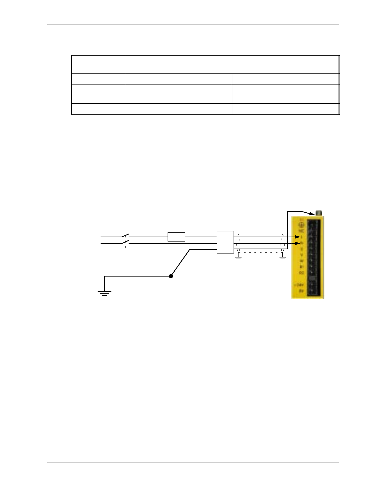
3.4.1 Single-phase connection to package sizes A, B, C, D
Location Connector X1
(Mating connector: Phoenix COMBICON MVSTBW 2,5/9-ST, 5mm pitch)
Part number FDH1A.../FPH1A... FDH2A.../FPH2A...
Nominal input
voltage
115VAC, 1Φ line to neutral 230VAC, 1Φ line to neutral
Range 97-125VAC 220-250VAC
For single-phase connection, the voltage ripple on the DC-bus is 25Vp-p for 5A peak current
rising to 50Vp-p for 10A peak current. This can limit the maximum speed of the motor.
Tightening torque for terminal block connections is 0.5-0.6Nm (4.4-5.3 lb-in).
The threaded hole in the top of the enclosure is for protective earth/ground connections.
The threaded hole in the bottom of the enclosure may be used as an additional functional
earth/ground connection for signals on connector X3. It may also be used to attach strain relief
clamps. The holes are threaded for M4 bolts no longer than 12mm (0.47 in) in length. Longer
bolts may short circuit the electrical components inside the FlexDrive
II
.
AC
Supply
Line (L)
Neutral (N)
Route L, N, and
earth/ground together
in conduit or cable
Circuit breaker or fuse.
See section 3.4.4
AC filter.
See section
3.4.5
STAR POINT
Incoming safety
earth/ground (PE)
Isolating switch
* If filter has no
output
earth/ground
terminal, earth
wire may be
connected directly
to star point.
*
If AC power wires
are shielded,
earth/ground
outer shield using
360º clamps
connected to
backplane.
Figure 2 - Earthing/grounding for single-phase installations
Note: For CE compliance, a filter must be connected between the AC power supply and
the FlexDrive
II
. If local codes do not specify different regulations, use at least the
same gauge wire for earth/ground as is used for L and N.
Page 24
3-10 Basic Installation MN1902
3.4.2 Three-phase connection to package sizes E, G, H
Location Connector X1A
(Mating connector: Phoenix POWER COMBICON PC4/..-ST- 7.62)
Part number FDH2A15.../FPH2A15... FDH4A.../FPH4A...
Nominal input
voltage
230VAC, 3Φ line to line 230-460VAC, 3Φ line to line
Range 184-253VAC 180-528VAC
Tightening torque for terminal block connections is 0.5-0.6Nm (4.4-5.3 lb-in). The threaded
hole in the top of the enclosure is for protective earth/ground connections. The threaded hole
in the bottom of the enclosure (if present) may be used as an additional functional
earth/ground connection for signals on connector X3. It may also be used to attach strain relief
clamps. The holes are threaded for M4 bolts no longer than 12mm (0.47 in) in length. Longer
bolts may short circuit the electrical components inside the FlexDrive
II
.
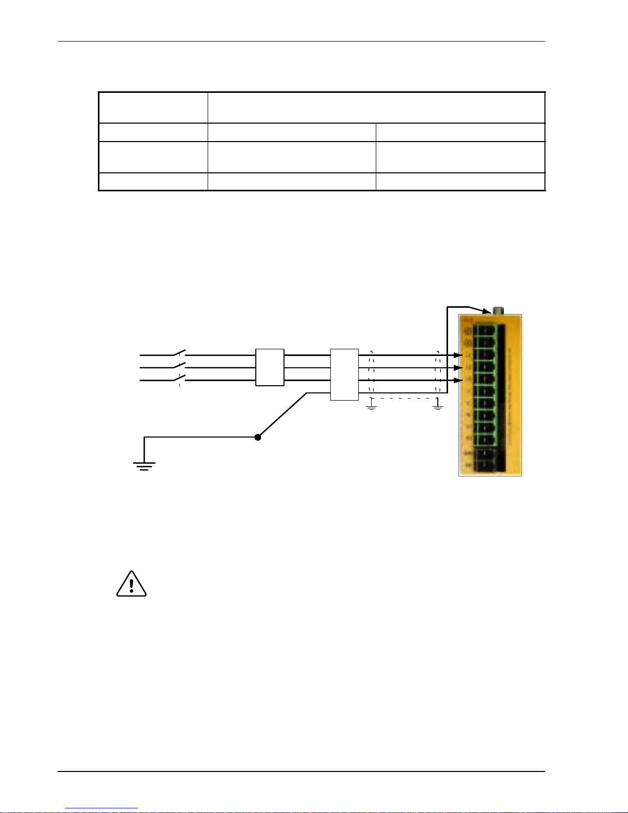
AC
Supply
Line (L1)
Route L1, L2, L3 and
earth/ground together
in conduit or cable
Circuit breaker or fuses.
See section 3.4.4
AC filter.
See section
3.4.5
Line (L2)
Line (L3)
STAR POINT
Incoming safety
earth/ground (PE)
Isolating switch
* If filter has no
output
earth/ground
terminal, earth
wire may be
connected
directly to star
point.
*
If AC power wires
are shielded,
earth/ground
outer shield using
360º clamps
connected to
backplane.
FDH4A... shown
for illustration
purposes
Figure 3 - Earthing/grounding for three-phase installations
WARNING: Drives with part numbers FDH2A15... or FPH2A15... have two
additional terminals on the X1 connector labeled Vcc+ and Vcc-.
The full output bus voltage is present on the these terminals so do not
make any connection to them.
Note: For CE compliance, a three-phase AC filter must be connected between the AC
power supply and the FlexDrive
II
. If local codes do not specify different
regulations, use at least the same gauge wire for earth/ground as is used for L
and N.
Page 25
Basic Installation 3-11MN1902
3.4.3 Input power conditioning
Baldor drives are designed for direct connection to standard single and three-phase lines
(depending on model) that are electrically symmetrical with respect to earth/ground. Certain
power line conditions must be avoided; an AC line reactor, an isolation transformer or a step
up/step down transformer may be required for some power conditions:
H If the feeder or branch circuit that provides power to the FlexDrive
II
has permanently
connected power factor correction capacitors, an input AC line reactor or an isolation
transformer must be connected between the power factor correction capacitors and the
FlexDrive
II
.
H If the feeder or branch circuit that provides power to the FlexDrive
II
has power factor
correction capacitors that are switched on line and off line, the capacitors must not be
switched while the drive is connected to the AC power line. If the capacitors are switched
on line while the drive is still connected to the AC power line, additional protection is
required. A Transient Voltage Surge Suppressor (TVSS) of the proper rating must be
installed between the AC line reactor (or isolation transformer) and the AC input to the
FlexDrive
II
.
3.4.3.1 Input power-cycling
If AC power has been removed from the FlexDrive
II
, it should not be reapplied for at least one
minute. This delay allows the input surge protection circuit to perform correctly. Power-cycling
the drive more frequently could cause nuisance trips when power is reapplied and reduce the
lifetime of the FlexDrive
II
.
3.4.4 Power disconnect and protection devices
A power disconnect should be installed between the input power service and the FlexDrive
II
for a fail-safe method to disconnect power. The FlexDriveIIwill remain in a powered condition
until all input power is removed from the drive and the internal bus voltage has depleted.
The FlexDrive
II
must have a suitable input power protection device installed. Recommended
circuit breakers are thermal magnetic devices (1 or 3 phase as required) with characteristics
suitable for heavy inductive loads (D-type trip characteristic). Recommended time delay fuses
are Buss FRN on 230V AC or equivalent, following the UL 508C recommendation of a fuse
size of four times the continuous output current of the drive. Dual element, time delay fuses
should be used to avoid nuisance trips due to inrush current when power is first applied.
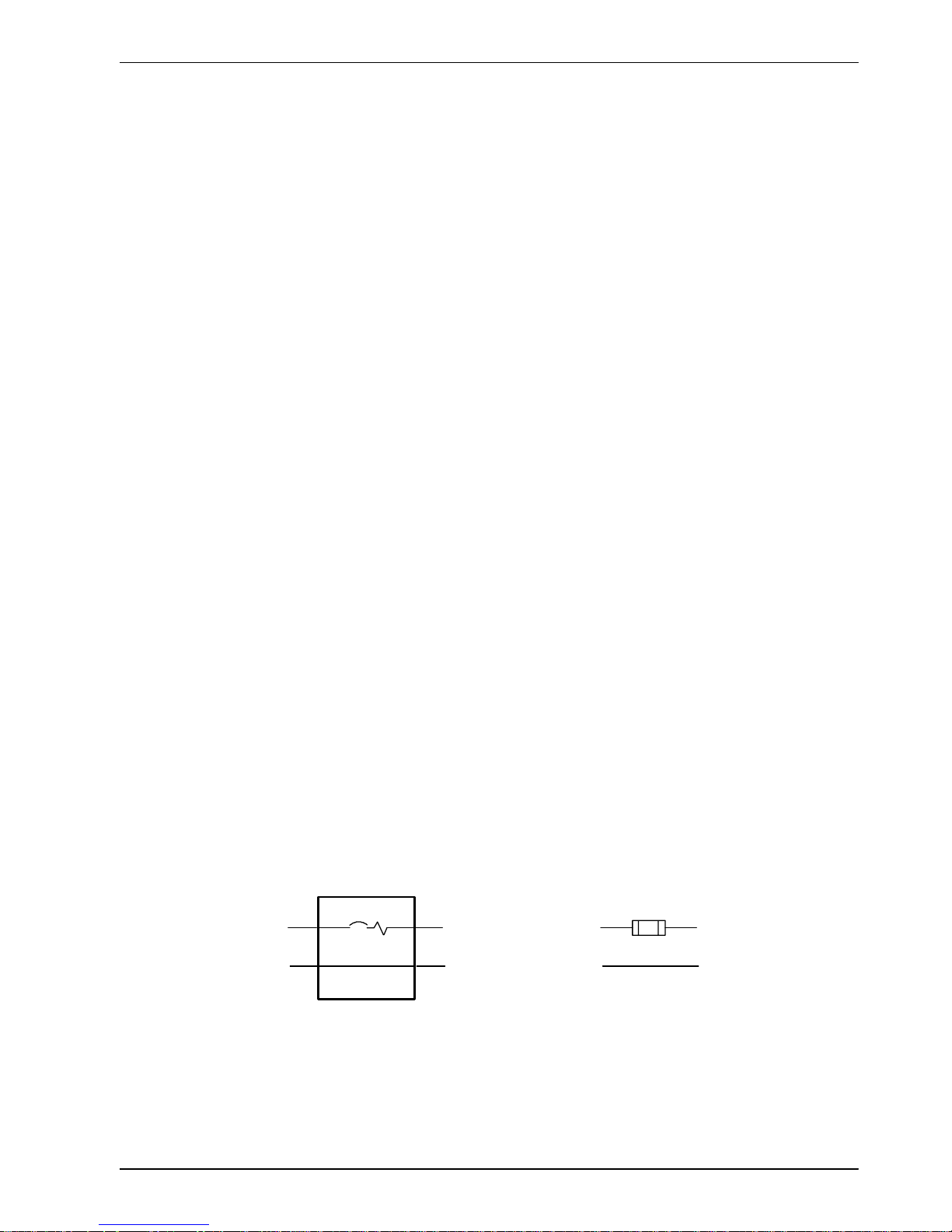
Circuit Breaker
L
N
From
supply
L
N
From
supply
Fuse
L
N
L
N
Figure 4 - Circuit breaker and fuse, single-phase (package sizes A, B, C, D)
Page 26
3-12 Basic Installation MN1902
Note: Power to single phase models may be derived by connecting two phases of an
appropriate three-phase supply (L1 and L2 for example). When supplying
AC
power in this way, the voltage between the two phases must not exceed the
rated
input voltage of the FlexDrive
II
. A two pole breaker must be used to isolate both
lines. Fuses must be fitted in both lines. Circuit breaker or fuse are not supplied.
For CE compliance, see Appendix C.
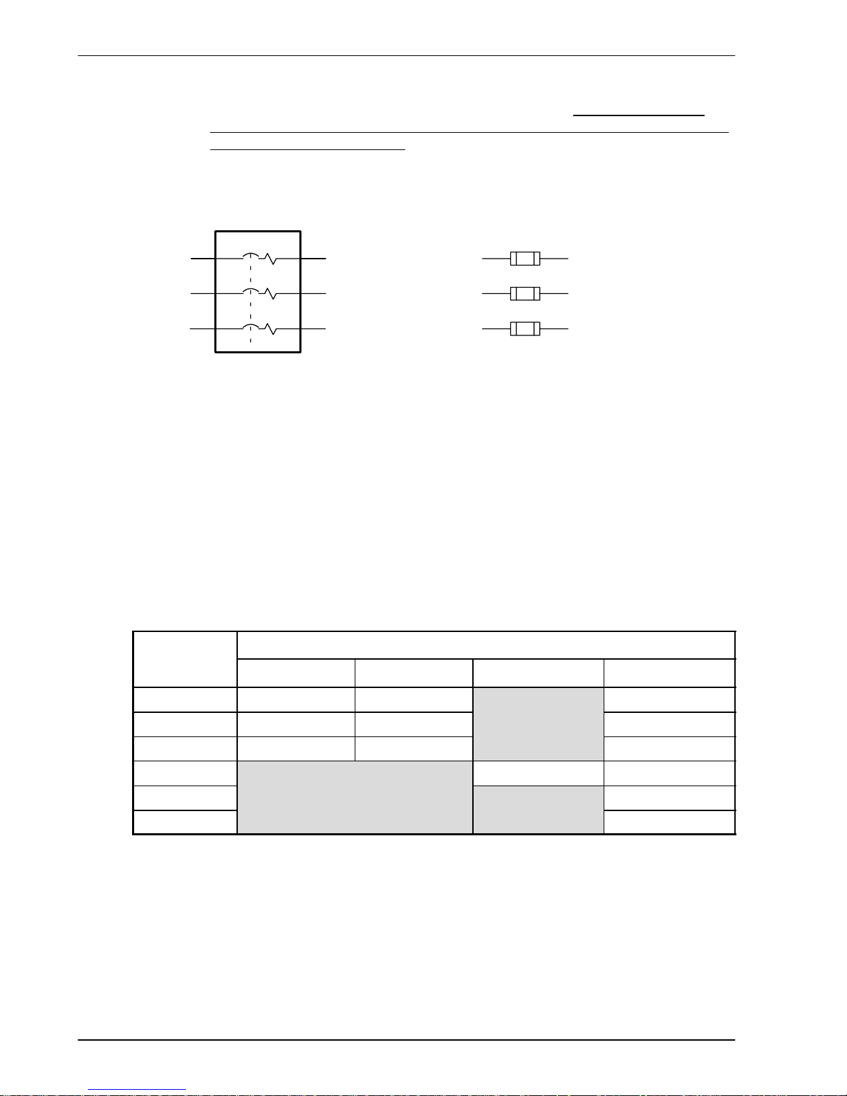
Circuit Breaker
Circuit breaker or fuse are not supplied.
For CE Compliance, see Appendix C.
L1
From
supply
Fuses
L2
L3
L1
L2
L3
From
supply
L1
L2
L3
Figure 5 - Circuit breaker and fuse, three-phase (package sizes E, G, H)
Note: Metal conduit or shielded cable should be used. Connect conduits so the use of a
line reactor or RC device does not interrupt EMI/RFI shielding.
3.4.5 Power supply filters
To comply with EEC directive 89/336/EEC, an AC power filter of the appropriate type must be
connected. This can be supplied by Baldor and will ensure that the FlexDrive
II
complies with
the CE specifications for which it has been tested. Table 1 lists the appropriate filters:
FlexDrive
II
Input voltages
curren
t
rating
115VAC, 1Φ 230VAC, 1Φ 230VAC, 3Φ 230-460VAC, 3Φ
2.5A FI0014A00 FI0019A00 FI0018A00
5A FI0015A00 FI0015A00
FI0018A00
7.5A FI0015A01 FI0015A01* FI0018A00
15A FI0018A01 FI0018A01
20A FI0018A01
27.5A FI0018A01
Ta ble 1 - Baldor filter part numbers
* If this model requires a customer supplied 24V control supply (catalog numbers
FDH2A07Tx-xxx3 or FPH2A07Tx -xxx3), use filter FI0015A02. For further details of power
supply filters see section A.1.6.
Page 27

Basic Installation 3-13MN1902
3.4.6 Wire sizes and protection device ratings
Table 2 describes the wire size to be used for power connections and the ratings of the
protection devices.
Incoming Power
Nominal
Continuous
D-Type
Time
Minimum
Catalog Number
Input
Output
y
p
Input
Dela
yMinimu
m
Wire Gauge
Vol
t
age
A
mps
(RMS)
B
reaker
(A)
I
npu
t
Fuse
(A)
AWG mm
2
FDH1A02xx-xxxx
FPH1A02xx-xxxx
115V
(1Φ)
2.5A 6 6 14 2.0
FDH2A02xx-xxxx
FPH2A02xx-xxxx
230V
(1Φ)
2.5A 6 6 14 2.0
FDH1A05xx-xxxx
FPH1A05xx-xxxx
115V
(1Φ)
5A 10 10 14 2.0
FDH2A05xx-xxxx
FPH2A05xx-xxxx
230V
(1Φ)
5A 10 10 14 2.0
FDH1A07xx-xxxx
FPH1A07xx-xxxx
115V
(1Φ)
7.5A 16 16 14 2.0
FDH2A07xx-xxxx
FPH2A07xx-xxxx
230V
(1Φ)
7.5A 16 16 14 2.0
FDH4A02xx-xxxx
FPH4A02xx-xxxx
230-460V
(3Φ)
2.5A 6 6 14 2.0
FDH4A05xx-xxxx
FPH4A05xx-xxxx
230-460V
(3Φ)
5A 10 10 14 2.0
FDH4A07xx-xxxx
FPH4A07xx-xxxx
230-460V
(3Φ)
7.5A 16 16 14 2.0
FDH2A15xx-xxxx
FPH2A15xx-xxxx
230V
(3Φ)
15A 32 32 12 3.3
FDH4A15xx-xxxx
FPH4A15xx-xxxx
230-460V
(3Φ)
15A 32 32 12 3.3
FDH4A20xx-xxxx
FPH4A20xx-xxxx
230-460V
(3Φ)
20A 40 40 10 5.3
FDH4A27xx-xxxx
FPH4A27xx-xxxx
230-460V
(3Φ)
27.5A 60 60 10 5.3
Table 2 - Protection device and wire ratings
Note: All wire sizes are based on 75°C (167°F) copper wire. Higher temperature smaller
gauge wire may be used per National Electric Code (NEC) and local codes.
Recommended fuses/breakers are based on 25°C (77°F) ambient, maximum
continuous control output current and no harmonic current. Earth/ground wires
must be the same gauge, or larger, than the Line and Neutral wires.
Page 28
3-14 Basic Installation MN1902
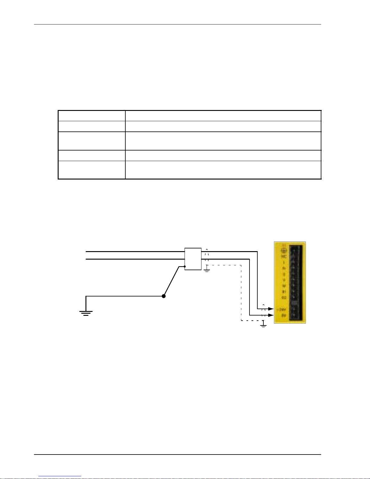
3.4.7 External customer supplied 24V control supply
Depending on model (catalog numbers FDHxxxxx-xxx3 and FPHxxxxx -xxx3) a 24VDC
control supply must be provided to power the control electronics. This is useful for safety
reasons where AC power needs to be removed from the power stage but the control
electronics must remain powered to retain position and I/O information. It is recommended
that a separate fused 24V supply is provided for the FlexDrive
II
. If other devices are likely to
be powered from the same 24V supply then a filter (Baldor catalog number FI0014A00) should
be installed to isolate the FlexDrive
II
from the rest of the system.
Location
Connector X1 / X1A
Part number FDHxxxxx -xxx3 or FPHxxxxx-xxx3
Nominal input
voltage
24V
Range 20.4-28.8VDC
Input current
(maximum)
1.75A continuous (4A power on surge)
Tightening torque for terminal block connections is 0.5-0.6Nm (4.4-5.3 lb-in)
Note: Connect 24V to connector X1 only if your model has this feature. Connecting 24V
to a model that does not require an external 24V supply (FDHxxxxx-xxx0 and
FPHxxxxx-xxx0) could damage the unit.
Customer supplied
24VDC (fused)
+24V
24V filter
(optional)
GND
Single-phase model
shown for illustration
purposes
STAR
POINT
Incoming safety
earth/ground (PE)
If 24V wires are
shielded,
earth/ground
outer shields,
using 360º
clamps connected
to backplane.
Figure 6 - Customer supplied 24V supply connections
Page 29
Basic Installation 3-15MN1902
3.5 Motor connections
The motor can be connected directly to the FlexDriveIIor through a motor contactor
(M-Contactor).
Location
Connector X1 / X1A
Part number
FDH1A...
FPH1A...
FDH2A...
FPH2A...
FDH2A15...
FPH2A15...
FDH4A...
FPH4A...
Nominal output voltage 160VDC 320VDC 320VDC 565/650V
Output voltage range 135-176VDC 306-350VDC 258-355VDC 254-746VDC
See
section
3.5.4
V
W
U
Motor
To earth/ground outer shield, use 360° clamps connected to backplane
Thermal
switch
A
B
Brake
(if present)
C
D
See
section
3.5.5
Unshielded
lengths should be
as short as
possible.
Optional motor
circuit contactors
Figure 7 - Motor connections
CAUTION: Do not connect supply power to the FlexDriveIIUVW outputs. The
FlexDrive
II
might be damaged.
CAUTION: The motor leads U, V and W must be connected to their corresponding U,
V or W terminal on the motor. Misconnection will result in uncontrolled
motor movement.
The motor power cable must be shielded for CE compliance. The connector or gland used at
the motor must provide 360 degree shielding. The maximum recommended cable length is
30.5m (100ft).
Note: For CE compliance the motor earth/ground should be connected to the drive
earth/ground.
Page 30
3-16 Basic Installation MN1902
3.5.1 Motor circuit contactors
If required by local codes or for safety reasons, an M-Contactor (motor circuit contactor) may
be installed to provide a physical disconnection of the motor windings from the FlexDrive
II
(see section 3.5). Opening the M-Contactor ensures that the FlexDriveIIcannot drive the
motor, which may be necessary during equipment maintenance or similar operations. Under
certain circumstances, it may also be necessary to fit a brake to a rotary motor. This is
important with hanging loads where disconnecting the motor windings could result in the load
falling. Contact your local supplier for details of appropriate brakes.
CAUTION: If an M-Contactor is installed, the FlexDriveIImust be disabled at least
20ms before the M-Contactor is opened. If the M-Contactor is opened
while the FlexDrive
II
is supplying voltage and current to the motor, the
FlexDrive
II
may be damaged. Incorrect installation or failure of the
M-Contactor or its wiring may result in damage to the FlexDrive
II
.
Ensure that shielding of the motor cable is continued on both sides of the contactor.
3.5.2 Motor power cable pin configuration - Baldor BSM rotary motors
Figure 8 shows the pin configuration for a typical Baldor motor cable, part number
CBL030SP-MHCE:
Signal name
Motor / cable pin Motor cable wire color
Motor U 1 Black, labeled ‘1’
Motor V 4 Black, labeled ‘2’
Motor W 3 Black, labeled ‘3’
Earth/ground 2 Green/Yellow
Thermal switch A Green
Thermal switch B White
Brake C Blue
Brake D Red
Cable connector end view
(female)
1
B
A
3
2
4
Motor power connector
(male)
1
B
A
3
2
4
C
D
C
D
Note:
Not all motors
arefittedwith
a brake so
pins C and D
might not be
connected.
Figure 8 - Baldor motor power cable pin configuration
Page 31

Basic Installation 3-17MN1902
3.5.3 Motor cable pin configuration - Baldor linear motors
The following table shows the pin colors used in a typical Baldor linear motor cable set, part
number A Y1763A00:
Signal name
Motor cable wire color
Motor U Black
Motor V Red
Motor W White
Motor ground Green
Thermal switch Blue
Thermal switch Orange
Signal name Hall cable wire color
Hall 1 (U) White
Hall 2 (V) Red
Hall 3 (W) Black
Hall ground Green
Hall +5VDC Brown
Page 32

3-18 Basic Installation MN1902
3.5.4 Thermal switch connection
You might wish to wire the motor’s thermal switch contacts (normally open), using a relay, to a
digital input on connector X3 (see section 4.3.1). Using the WorkBench v5 Digital I/O tool, the
input can be configured to be the motor trip input. This allows the FlexDrive
II
to respond to
motor over-temperature conditions. The Mint keyword MOTORTEMPERATUREINPUT can also
be used to configure a digital input for this purpose. A typical circuit, using DIN1 as the input,
is shown in Figure 9.
A
B
motor
thermal
switch
CREF
X3
7
DIN0 (INX.0)
Relay
Customer
supplied
24VDC
supply
+24VDC 0V
10
11
12
13
14
15
16
17
DIN1 (INX.1)
DIN3 (INX.3)
DIN7 (INX.7)
DIN5 (INX.5)
DIN4 (INX.4)
DIN2 (INX.2)
DIN6 (INX.6)
Separate
customer
supplied
24VDC supply
+24VDC 0V
Figure 9 - Motor thermal switch circuit
CAUTION: The 24VDC power supply connected to the thermal switch must be a
separate supply as shown in Figure 9. Do not use the 24V supply used
for the drive enable signal, or the internally generated supply (if present).
The thermal switch wires often carry noise that could cause erratic drive
operation or damage. The thermal switch contacts must never be wired
directly to a digital input.
The separate 24VDC supply used for the thermal switch may also be
used for the motor brake circuit (section 3.5.5).
Page 33

Basic Installation 3-19MN1902
3.5.5 Motor brake connection
You might wish to wire a motor’s brake, via relays, to digital outputs on connector X3 (see
section 4.3.1). This provides a way for the Mint program to control the motor’s brake. A typical
circuit is shown in Figure 10.
C
D
from motor brake
connections
Separate
customer
supplied
24VDC supply
X3
8
18
19
DOUT0 (OUTX.0)
DOUT1 (OUTX.1)
CGND
Relay 2
Relay 1
+24VDC 0V
The inner shield
surrounding the
brake wires should
be earthed/grounded
at one point only.
The relays have normally open
contacts and are shown deactivated
(contacts open, brake engaged).
Figure 10 - Motor brake control circuit
This circuit uses the drive enable signal (configured using DRIVEENABLEOUTPUT to appear
on DOUT0) in conjunction with DOUT1. With this configuration, the following sequences can
be used to control the brake.
To engage the brake:
H The motor is brought to rest under normal control;
H Relay 2 is deactivated, causing the brake to engage;
H The drive is disabled. This removes power from the motor and causes Relay 1 to be
deactivated.
To disengage the brake:
H The drive is enabled, activating Relay 1;
H Power is applied to the motor to hold position under normal control;
H Relay 2 is activated, causing the brake to be disengaged.
CAUTION: The 24VDC power supply must be a separate supply as shown in Figure
10. Do not use the 24V supply powering the FlexDrive
II
digital outputs, or
the internally generated supply (if present). The brake wires often carry
noise that could cause erratic drive operation or damage. The brake
contacts must never be wired directly to the digital outputs. The relay(s)
should be fitted with a protective flyback diode, as shown.
The separate 24VDC supply used for the motor brake may also be used
to power the relay in the thermal switch circuit (section 3.5.4).
Page 34

3-20 Basic Installation MN1902
3.6 Regeneration resistor (Dynamic Brake resistor)
The 2.5A and 5A FlexDriveIIboth have an internally fitted regeneration resistor *. For 7.5A,
15A, 20A and 27.5A FlexDrive
II
, an external regeneration resistor must be installed to
dissipate excess power from the internal DC bus during motor deceleration.
Suitable regeneration resistors are listed in section A.1.7.
WARNING: A regeneration resistor may generate enough heat to
ignite combustible materials. To avoid fire hazard,
keep all combustible materials and flammable vapors
away from the resistors.
The regeneration resistor should be mounted near the top of an enclosure
to maximize heat dissipation. When the motor regenerates, the yellow
DB On LED on the front panel of the FlexDrive
II
will illuminate.
* If required by the application, additional external resistors connected to R1 and R2 will be
connected in parallel with the internal resistor.
3.6.1 Controlling regeneration
Some regeneration resistor assemblies include an overload switch to indicate when too much
power is being dissipated by the resistor. This switch can be wired to a digital input on the
FlexDrive
II
. Using the WorkBench v5 Digital I/O tool, the input can be configured to be the
brake trip input. This allows the FlexDrive
II
to respond to resistor overload conditions.
The Mint keyword DBEXTTRIPINPUT can also be used to configure a digital input for this
purpose. On three-phase FlexDrive
II
models, the operation of the regeneration resistor can be
controlled by further Mint keywords. These also begin with the letters DB..., for example
DBEXTPEAKPOWER. See the Mint help file for details.
R1
R2
Page 35

Basic Installation 3-21MN1902
3.7 Feed b ack connectio n s
Two feedback options are available for use with linear and rotary motors - commutating
encoder or resolver. Confirm the catalog number of your FlexDrive
II
(see section 2.2.1) to
ensure you are wiring the correct feedback device. There are some important considerations
when wiring the feedback device:
H The feedback device wiring must be separated from power wiring.
H Where feedback device wiring runs parallel to power cables, they must be separated by at
least 76mm (3 in)
H Feedback device wiring must cross power wires at right angles only.
H To prevent contact with other conductors or earths/grounds, unearthed/ungrounded ends
of shields must be insulated.
H Some larger D-type connector shells may be obstructed by neighboring connector X3.
H Linear motors use two separate cables (encoder and Hall). The cores of these two cables
will need to be wired to the appropriate pins of the 15-pin D-type mating connector
(supplied).
An encoder output signal is available on connector X7 for supplying other equipment.
FlexDrive
II
models with the resolver option provide a simulated encoder output, while the
encoder based FlexDrive
II
duplicates the encoder signals entering X8. See section 4.4.1 for
details.
Page 36

3-22 Basic Installation MN1902
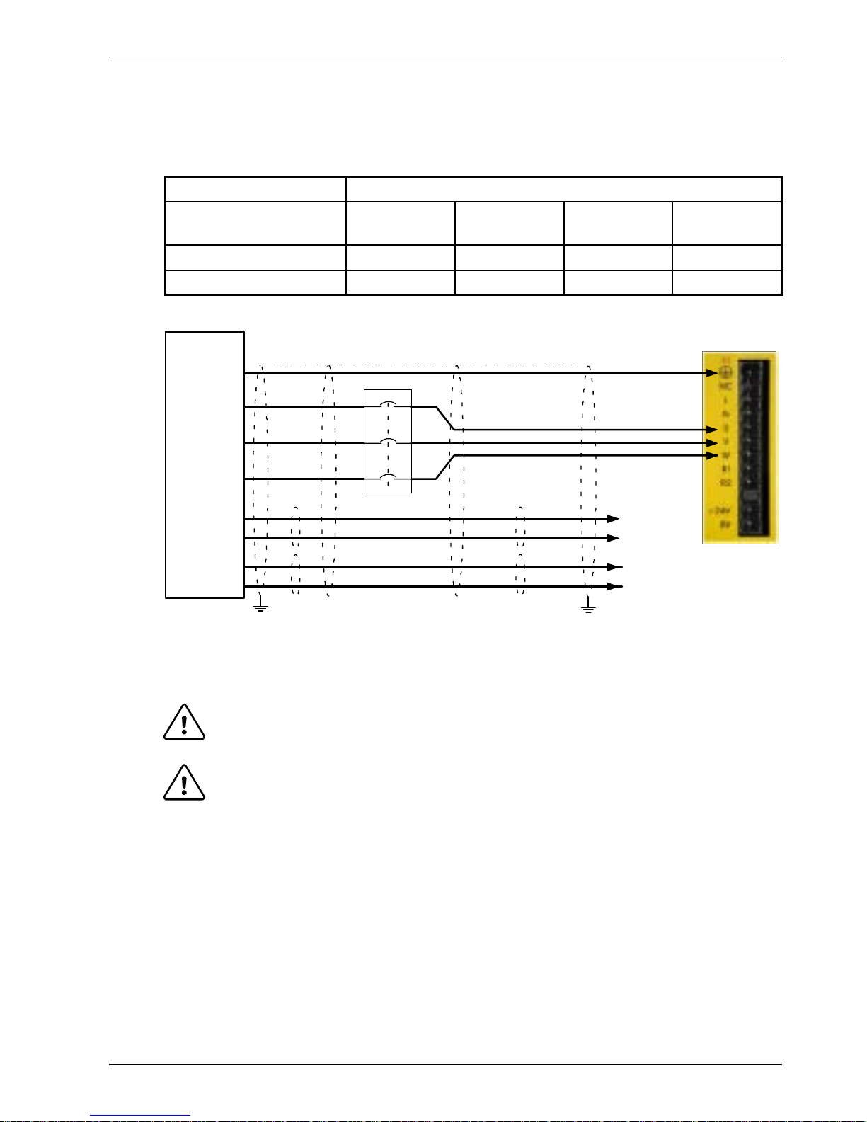
3.7.1 Resolver option - X8
The resolver connections are made using the 9-pin D-type male connector X8. Twisted pair
cables must be used for the complementary signal pairs e.g. SIN+ and SIN-. The overall cable
shield (screen) must be connected to the metallic shell of the D-type connector.
Location
Connector X8, 9-pin D-type male connector
Pin Resolver function
1 REF+
2 COS+
3 SIN+
4 (NC)
5 Analog Ground
6 REF-
7 COS-
8 SIN-
9 Chassis Ground
Description Resolver input with 14-bit resolution
The resolver input is used to create an encoder signal inside the FlexDriveII. This provides the
FlexDrive
II
with an equivalent resolution of 4096 pulses per revolution (ppr), although this can
be reconfigured in the WorkBench v5 Commissioning Wizard to provide 1024 ppr. The
FlexDrive
II
provides an input accuracy of ±3 counts. When used with a typical Baldor BSM
series resolver motor the combined accuracy is ±11 counts (calculated with the input
equivalent resolution set to the factory preset value of 4096 ppr).
1
6
2
7
3
8
5
R2
R1
S2
S4
S1S3
X8
SIN+
SIN-
COS+
COS-
REF+
REF-
AGND
+
Twisted
pairs
Baldor motor
resolver connector
5
6
3
4
1
2
Connect overall shield
to connector backshells.
Connect internal
shields to AGND.
+
+
Figure 11 - Resolver cable connections
1
5
6
9
Page 37

Basic Installation 3-23MN1902
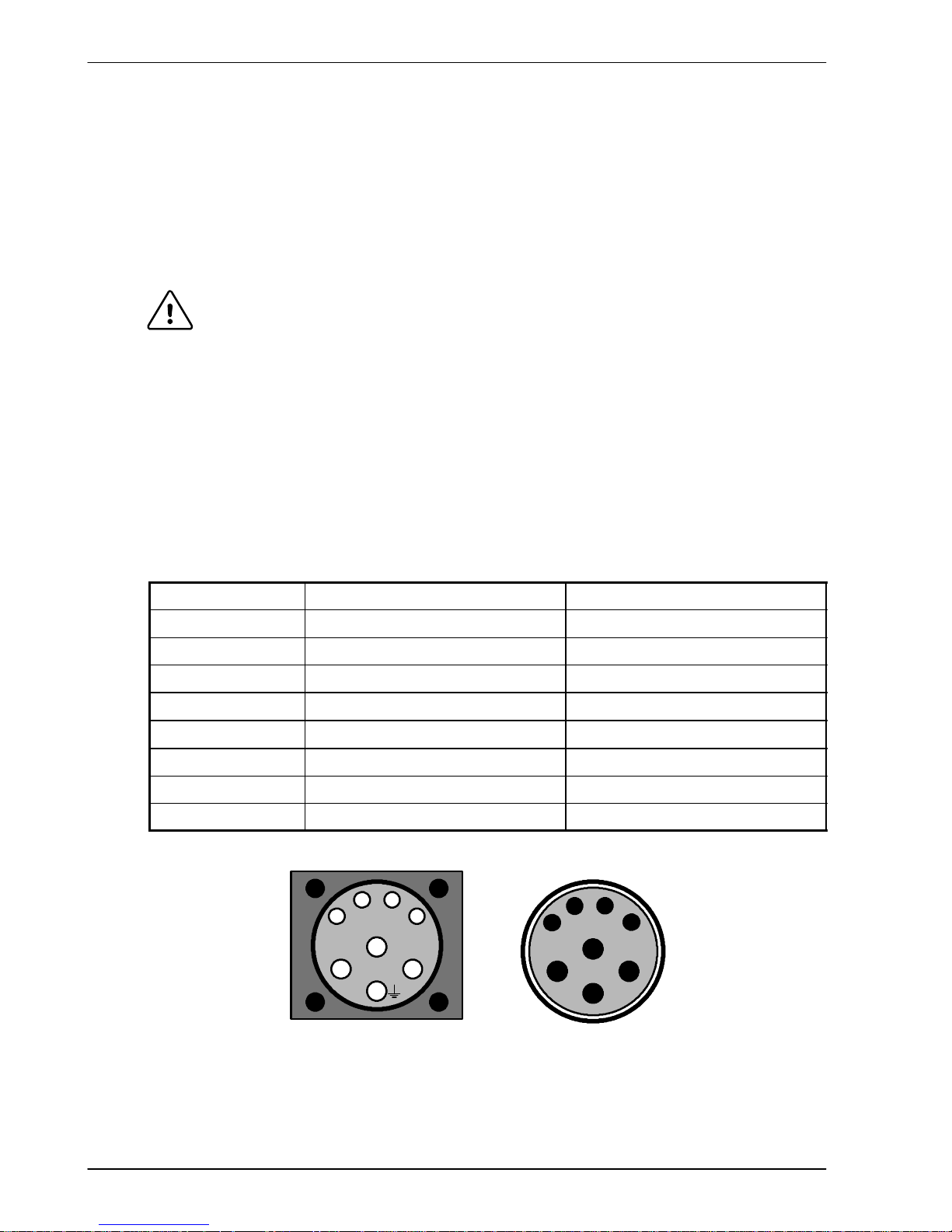
3.7.1.1 Resolver cable pin configuration
Figure 12 shows the pin configuration for a typical Baldor resolver feedback cable, part
number CBL030SF-ALCE.
Signal name
FlexDrive
II
X8 pin
Motor / cable
pin
Baldor resolver cable
internal wire colors
REF+ 1 1 Red
REF- 6 2 Blue
COS+ 2 3 Green
COS- 7 4 Yellow
SIN+ 3 5 Pink
SIN- 8 6 Grey
1
2
3
45
6
7
89
101112
Motor resolver connector
(male)
Pins 7-12
are not us ed
and may not
be present
1
2
3
45
6
7
89
10
11
12
Cable connector end view
(female)
Figure 12 - Baldor motor resolver cable pin configuration
The maximum recommended cable length is 30.5m (100ft).
Page 38

3-24 Basic Installation MN1902
3.7.2 Encoder option - X8
The encoder connections (ABZ channels and Hall signals) are made using the 15-pin D-type
female connector X8. Twisted pair cables must be used for the complementary signal pairs
e.g. CHA+ and CHA-. The overall cable shield (screen) must be connected to the metallic
shell of the D-type connector.
Location
Connector X8, 15-pin D-type female connector
Pin Encoder function
1 CHA+
2 CHB+
3 CHZ+
4 Hall U+
5 Hall U-
6 CHA-
7 CHB-
8 CHZ-
9 Hall W+
10 Hall V+
11 +5V out
12 (NC)
13 DGND
14 Hall W-
15 Hall V-
Description Commutating (UVW) encoder input, non-isolated. Pin 11
provides +5V for encoders requiring power (200mA max)
CHA+
CHA-
CHB+
CHB-
+5V
DGND
1
6
2
7
3
8
11
X8
CHZ+ (INDEX)
CHZ- (INDEX)
4
5
9
14
10
15
13
Hall U+
Hall U-
Hall W+
Hall WHall V+
Hall V-
12 (NC)
Hall
Feedback
Connect overall shield
to connector backshells.
Twisted pai rs
Connect internal
shields to DGND.
Encoder
Feedback
Motor
Figure 13 - Encoder cable connections - rotary motors
1
5
15
6
11
10
Page 39

Basic Installation 3-25MN1902
3.7.2.1 Encoder cable pin configuration - rotary motors
Figure 14 shows the pin configuration for a typical Baldor encoder feedback cable, part
number CBL030SF-KPCEA3.
Signal name
FlexDrive
II
X8 pin
Motor / cable
pin
CHA+ 1 3
CHA- 6 4
CHB+ 2 5
CHB- 7 6
CHZ+ 3 7
CHZ- 8 8
Hall U+ 4 10
Hall U- 5 11
Hall V+ 10 12
Hall V- 15 13
Hall W+ 9 14
Hall W- 14 15
+5V 11 1
DGND 13 2
Motor encoder connector
(male)
Pins 9 and 16
are not
connected
1
2
3
4
5
6
7
8
9
10
11
12
13
1415
16
Cable connector end view
(female)
1
2
3
4
5
6
7
8
9
10
11
12
13
14 15
16
Figure 14 - Baldor rotary motor encoder cable pin configuration
The maximum recommended cable length is 30.5m (100ft).
Page 40

3-26 Basic Installation MN1902
3.7.2.2 Encoder cable connections - linear motors
CHA+
CHA-
CHB+
CHB-
+5V
DGND
1
6
2
7
3
8
11
X8
Encoder
Feedback
CHZ+ (INDEX)
CHZ- (INDEX)
4
5
9
14
10
15
13
Hall U+
Hall U-
Hall W+
Hall WHall V+
Hall V-
12 (NC)
Hall
Feedback
Connect overall shield to
connector backshells.
Twisted pai rs
Connect internal
shields to DGND.
Leave pins
5, 12, 14, 15
unconnected
Motor
Figure 15 - Encoder cable connections - linear motors
3.7.2.3 Encoder cable pin configuration - linear motors
Linear motors use two separate cables (encoder and Hall). The cores of these two cables
must be wired to the appropriate pins of the 15-pin D-type mating connector (supplied):
Signal name
FlexDrive
II
X8 pin
Encoder cable internal wire colors
CHA+ 1
CHA- 6
CHB+ 2
Please refer to MN1800 Linear Motors
CHB- 7
PleaserefertoMN1800
LinearMotor
s
Installation & Operating Manual for details.
CHZ+ 3
CHZ- 8
Baldor Hall cable internal wire colors
Hall U+ 4 White
Hall V+ 10 Red
Hall W+ 9 Black
+5V 11 Brown
Hall GND 13 Green
Page 41

Basic Installation 3-27MN1902
3.7.3 EnDat (absolute encoder) option - X8
The absolute encoder interface supports both incremental and absolute (multi and single turn)
feedback using SinCos technology. It is possible to read and write information to the encoder.
The absolute encoder connections are made using the 15-pin D-type female connector X8.
Twisted pair cables must be used for the complementary signal pairs e.g. SinA+ and SinA-.
The overall cable shield (screen) must be connected to the metallic shell of the D-type
connector.
Location
Connector X8, 15-pin D-type female connector
Pin Encoder function
1 Data+
2 Data-
3 (Reserved - do not connect)
4 +5V
5 DGND
6 Shield
7 Cos B-
8 (Reserved - do not connect)
9 Clock-
10 Clock+
11 (Reserved - do not connect)
12 Sin A-
13 Sin A+
14 Cos B+
15 (Reserved - do not connect)
Description Absolute encoder input, non-isolated. Pin 4 provides
power to the encoder (200mA max)
Data+
Data-
Cos BCos B+
1
2
7
14
12
13
X8
Absolute
Encoder
Sin ASin A+
6
Twisted p airs
109Clock+
Clock-
5DGND
Chassis
4+5V
Connect overall shield
to connector backshells.
Connect internal
shields to pin 6.
Motor
Figure 16 - Absolute encoder cable connections
1
5
15
6
11
10
Page 42

3-28 Basic Installation MN1902
3.7.3.1 Absolute encoder cable pin configuration
Figure 17 shows the pin configuration for a typical Baldor absolute encoder feedback cable,
part number CBL030SF-KLCEA3.
Signal name
FlexDrive
II
X8 pin
Motor / cable
pin
Data - 2 1
Sin A+ 13 2
Cos B+ 14 4
Clock- 9 5
Clock + 10 7
Cos B- 7 8
+5V 4 9
DGND 5 10
Sin A- 12 11
Data + 1 12
1
2
3
45
6
7
89
101112
Motor absolute encoder connector
(male)
1
2
3
45
6
7
89
10
11
12
Cable connector end view
(female)
Figure 17 - Baldor rotary motor absolute encoder cable pin configuration
The maximum recommended cable length is 30.5m (100ft).
Page 43

Basic Installation 3-29MN1902
3.8 Drive enable - X3
Location Connector X3, pins 7 & 9 (Mating connector:
Phoenix MINI-COMBICON MC 1.5/20-ST-3,5)
Name Drive enable
Input voltage +24VDC (±20%)
To enable the FlexDriveIIand allow motion, three actions are necessary:
H A customer supplied externally generated 24VDC supply must be
connected between pins 7 and 9.
H The drive enable DIP switch (switch 8) must be in the On position.
H A drive enable command must be received.
These actions are explained in the following sections.
3.8.1 Drive enable - X3
The wiring to the drive enable input can be connected in one of two ways. Because CREF is
common to all the digital inputs, this has an effect on the sense of DIN0 to DIN7. Either
method provides a suitable drive enable input:
Active high
To cause the digital inputs to be active high (active when a voltage of +24VDC is applied to
them) connect +24VDC to pin 9 and 0V to pin 7 (CREF).
Active low
To cause the digital inputs to be active low (active when grounded) connect +24VDC to pin7
(CREF) and 0V to pin 9.
The drive enable connection can be wired directly or through an intermediate switch. If a
switch is used it should always be used to switch the signal to pin 9, with the signal to pin 7
(CREF) being hard-wired.
The sense of the digital inputs can also be configured in WorkBench v5 using the Digital inputs
tab of the Digital I/O tool. Alternatively, the Mint INPUTACTIVELEVEL keyword can be used to
select the sense of all the digital inputs (except drive enable).
The state of the drive enable input is displayed in the WorkBench v5 Spy window. It can also
be checked (but not set) using the Mint keyword DRIVEENABLESWITCH. See the Mint help file
for details.
ENABLE 9
CREF 7
Page 44

3-30 Basic Installation MN1902
3.8.2 Drive enable - SW1 DIP switch
To enable the FlexDriveIIthe front panel DIP switch 8 must be set to On.
This switch provides a local enable/disable switch that can be useful
during testing.
The state of the drive enable DIP switch is displayed in the WorkBench v5
Spy window. It can also be checked (but not set) using the Mint keyword
ENABLESWITCH. See the Mint help file for details.
See section 3.9 for full details of other DIP switch functions.
3.8.3 Drive enable command
The other action required to enable the FlexDriveIIcan be controlled either by software or
hardware.
Note: This method is explained here for your information, but cannot be completed until
you have installed the software and are ready to turn on AC power to the drive.
Please continue to read all sections in sequence. Do not turn on AC power until
you reach the appropriate instructions.
In software, a drive enable command must be issued. The easiest way to do this is by clicking
the Drive enable button
in WorkBench v5. Alternatively, the Mint commands RESET or
DRIVEENABLE=1 can be used. See the Mint help file for details.
In hardware, a digital input can be used to create the drive enable command. This can be
configured in WorkBench v5 using the Digital inputs tab of the Digital I/O tool. Alternatively, the
Mint keyword RESETINPUT can be used to select the required digital input. See the Mint help
file for details.
Another method is to use the Mint keyword DRIVEENABLEMODE. This allows the combination
of DIP switch 8 and the Enable input to create the drive enable command. Both inputs must
become active. Provided one input is already on, as soon as the other input changes from off
to on (active), the drive will be enabled. See the Mint help file for details.
On
8
Page 45

Basic Installation 3-31MN1902
3.9 DIP switches - SW1
Various functions of the FlexDriveIIcan be controlled by the front panel SW1 DIP switches.
Location
Switch block SW1
Switch Function
1 8
2 4
Node number selection (serial and fieldbus networks)
3 2
Nodenumberselection(serialandfieldbusnetworks
)
Bit pattern values shown in italics
4 1
5 Hold
6 RS485 terminator
7 Offset tuning
8 Enable
9 (Reserved)
10 RS232/RS485 select
Description 10-way DIP switch module for major functions
3.9.1 Switches 1-4
Switches 1-4 set the network node number (address) after the next power off/on cycle.
The switches can be used to select any node number from 1 to 14, as shown in Figure 18.
Switch
1
Switch
2
Switch
3
Switch
4
Node number
(address)
Off Off Off Off Set by Mint NODE keyword
Off Off Off On 1
Off Off On Off 2
Off Off On On 3
Off On Off Off 4
Off On Off On 5
Off On On Off 6
Off On On On 7
On Off Off Off 8
On Off Off On 9
On Off On Off 10
On Off On On 11
On On Off Off 12
On On Off On 13
On On On Off 14
On On On On Do not use!
See section 3.9.7
Figure 18 - Node number (address) switch settings
OnOff
Page 46

3-32 Basic Installation MN1902
If switches 1-4 are all in the Off position, the Mint NODE keyword can be used to set the node
number. WorkBench v5 (see section 5.2) reads the FlexDrive
II
node number (during the scan
process) and then uses it to direct commands to the FlexDrive
II
.
Avoid accidentally setting switches 1-4 to the On position at the same time. In combination
with DIP s witch 8, this will reset the FlexDrive
II
to its factory defaults. See section 3.9.7.
3.9.2 Switch 5 - Hold
Switch 5 stops the motor. In the Off position, normal operation is allowed. When switched to
the On position, the motor decelerates to rest and maintains position. The switch position is
sampled every 100ms.
3.9.3 Switch 6 - RS485 terminator
Switch 6 is used to connect a termination resistor to the RS485 network. In the Off position,
the RS485 network is unterminated at the FlexDrive
II
. In the On position, an internal 120Ω
termination resistor is connected between the RX+ and RX- signals - see section 4.4.5.
Switch 6 should remain in the Off position when using RS232.
3.9.4 Switch 7 - Offset tuning
Switch 7 is used to start offset tuning on analog (command) input AIN0. The purpose of offset
tuning is to remove DC offset voltages on analog input 0 (the command reference input) to
achieve a stationary motor shaft with 0VDC at the input. Confirm that the device supplying the
AIN0 command input is set to its intended zero output setting (nominally 0VDC) before starting
offset tuning. When switch 7 is in the On position, offset tuning will start the next time Enable
(switch 8) is changed from On to Off.
On
7
Wait for 1 second
for offset tuning
to be completed.
Off
7
1. 2. 3. 4.
Off
8
On
8
Figure 19 - Offset tuning using switch 7 and 8
Leave switch 7 Off in normal use. After offset tuning, remember to set switch 8 to the On
position to allow the drive to be enabled. The switch positions are sampled every 100ms. The
Mint keyword ADCOFFSETTRIM canbeusedtoperformthesameaction.
3.9.5 Switch 8 - Enable
Switch 8 must be set to On to allow the drive to be enabled. The switch position is sampled
every 100ms. However, two other actions are necessary to enable the FlexDrive
II
:
H The enable input (see section 3.8) must be active.
H The drive must also be enabled by using a drive enable command (see section 3.8.3).
Page 47

Basic Installation 3-33MN1902
3.9.6 Switches 9 and 10 - RS232/RS485 select
Switch 9 is reserved for Baldor keypad selection.
Switch 10 selects RS232 communications (Off) or RS485/RS422 (On) the next time the
FlexDrive
II
is power-cycled.
3.9.7 Factory settings
If switches 1-4 are all in the On position and switch 8 is set to Off, the FlexDriveIIwill be reset
to its preset factory settings at power on (or whenever the processor is reset by
WorkBench v5).
CAUTION: Use this function carefully - it will erase your drive setup information.
When using the SW1 DIP switches to reset the FlexDrive
II
to its factory defaults, all
parameters including the node number and serial communications baud rate will be reset.
In WorkBench v5, this means it will be necessary to rescan for the FlexDrive
II
(by starting a
new project) to enable communication. It will also be necessary to re-tune your motor and
drive.
On
1
Reapply
power.
1. 2.
On
2
On
3
On
4
FlexDriveIIwill
be reset to its
preset factory
settings.
3.
Off
8
Remove
power.
4.
Figure 20 - Resetting the FlexDriveIIto its factory default settings
The Mint keyword FACTORYDEFAULTS canalsobeusedtoresettheFlexDrive
II
to its factory
defaults. However, it will not reset the node number or serial communications baud rate. See
the Mint help file for details.
Page 48

3-34 Basic Installation MN1902
3.9.8 Preventing a program running at startup
Flex+DriveIIonly:
If switches 5 and 9 are set to On and switch 8 is set to Off, any program already in the
Flex+Drive
II
that contains an Auto command will be prevented from running automatically at
startup.
On5
Reapply power. Mint program
with Auto command will not run.
1. 2.
On9
3.
Off 8
Remove
power.
Figure 21 - Preventing the Auto command from running a stored Mint program
This completes the basic installation.
You should read the following sections in sequence
before attempting to start the FlexDrive
II
.
Page 49

Input / Output 4-1MN1902
4.1 Introduction
This section describes the various digital and analog input and output capabilities of the
FlexDrive
II
, with descriptions of each of the connectors on the front panel.
The following conventions will be used to refer to the inputs and outputs:
I/O Input / Output..............
DIN Digital Input.............
DOUT Digital Output...........
AIN Analog Input.............
AOUT Analog Output...........
CH Encoder channel.............
4.2 Analo g I/O
The FlexDriveIIprovides as standard:
H 1 analog input on the connector block X3 (command input)
The analog input is not optically isolated from internal power rails, so care must be taken to
avoid earth/ground loops and similar associated problems. The input buffers provide low pass
filtering of the applied voltage. To minimize the effects of noise, the analog input signal should
be connected to the system using individual shielded / screened cable (a twisted pair cable in
the case of differential operation) with an overall shield. The overall shield should then be
connected to the chassis at one end only. No other connection should be made to the shield.
If the input is unused, then it is advisable to connect it to the AGND pin. Do not leave the input
unconnected (floating).
4 Input / Output
4
Page 50

4-2 Input / Output MN1902
4.2.1 Analog input - X3 (command)
Location
Connector X3, pins 1-3
(Mating connector:
Phoenix MINI-COMBICON MC 1.5/20-ST-3,5)
Name AIN0
Mint keyword ADC.0
Description Single ended or differential input.
Common mode voltage range: ±10VDC.
Resolution: 14-bit with sign (accuracy ±4.9mV)
Common mode rejection: 40dB
Input impedance: >5kΩ
Sampling interval: 500µs - Software (Mint programs)
125µs - High speed command
reference signal
Analog input X3 can be connected as either a differential or a single ended input as shown in
Figure 22.
AIN0-
Pin 2
AIN0+
Pin 1
10k
LF412
AGND
Mint
ADC.0
FlexDrive
II
10k
10k
10k
-15V+15V
-15V+15V
20k
-
+
20k
Low pass filter &
level correction
(inverts signal)
Figure 22 - AIN0 analog input circuit
1
2
3
Page 51

Input / Output 4-3MN1902
AIN0
(ADC.0)
X3
AIN0
(ADC.0)
1
2
3
X3
AIN0-
Differential connection Single ended connection
AIN0+
1
2
3
AIN0+
GND
Figure 23 - AIN0 analog input wiring
AIN0
1kΩ, 0.25W
potentiometer
(ADC.0)2
1
X3
1.5kΩ, 0.25W
0V
+24VDC
3
Figure 24 - Typical input circuit to provide 0-10V (approx.) input from a 24V source
Page 52

4-4 Input / Output MN1902
4.2.2 Relay output - X3
Location Connector X3, pins 4 (+) & 5 (-)
Name General purpose relay
Mint keyword RELAY
Description Relay switch contacts controlled by Mint, rated at 1A,
30VDC. Normally closed.
Update interval: Immediate
The factory preset assignment for the relay is as the global error output signal
(see the Mint keyword GLOBALERROROUTPUT). When an error occurs the relay
is de-energized and the normally closed relay contacts are opened.
When the error is cleared, the relay is re-energized and the contacts are
closed. The relay can be also be controlled directly by the Mint keyword RELAY.
When the relay is de-energized (RELAY=_off) the contacts open.
An axis can use the relay as its drive enable output signal. This can be configured in
WorkBench v5 or by using the Mint keyword DRIVEENABLEOUTPUT. This prevents
access by RELAY, but means that the relay can be used to monitor the state of the
DRIVEENABLE keyword. See the Mint help file for details.
Internal relay
FlexDrive
II
Relay +
Pin 4
Relay Pin 5
Control
circuitry
Figure 25 - Relay contact outputs
4
5
Page 53

Input / Output 4-5MN1902
4.3 Digital I/O
The FlexDriveIIprovides as standard: *
H 8 general-purpose inputs on connector block X3
H 3 general-purpose outputs on connector block X3
A digital input can be used to support many typical input functions:
H Error input
H Reset input
H Stop input
H Forward limit
H Reverse limit
H Interrupts (controlled from Mint)
H Regeneration resistor (Dynamic Brake) overtemperature input
H PLC Task input conditions
H General purpose use.
Flex+Drive
II
only:
H Home input
H Index selection and triggering for preset move types
H DIN4 and DIN5 are fitted with Schmitt trigger devices and can be configured using Mint for
position capture of the axis or the master/auxiliary encoder positions. See section 4.3.4.
H The main axis’ fast input (assigned using the Mint keyword FASTSELECT) can also be
used as a trigger for point to point move types. See the Mint help file for details.
* Additional I/O is available on connector X12 if the option B is fitted. See MN1908 CAN &
Auxiliary I/O option for Flex+Drive
II
and MintDriveII.
Page 54

4-6 Input / Output MN1902
4.3.1 Digital inputs - X3
Location Connector X3
Pin Name Mint keyword
9 Drive Enable -
10 DIN0 INX.0
11 DIN1 INX.1
12 DIN2 INX.2
13 DIN3 INX.3
14 DIN4 INX.4
15 DIN5 INX.5
16 DIN6 INX.6
17 DIN7 INX.7
Description Eight general-purpose optically isolated AC digital inputs.
One committed drive enable input (Drive Enable).
Sampling interval: 2ms
The digital inputs DIN0 - DIN7 can be read individually using the associated Mint keyword INX
(for example INX.7) and can be configured for many user definable functions. Each input
circuit contains an opto-isolator as shown in Figure 26. Inputs DIN4 and DIN5 can also be
used as fast inputs - see section 4.3.4. The state of each digital input is displayed in the
WorkBench v5 Spy window.
Active high: DINx=+24VDC (±20%)
CREF=0V
CREF
Pin 7
DIN0
Pins 10
4k7
1k 0.1µF
NECPS2565
DGND
Mint
INX.0
10k
Vcc
FlexDrive
II
Active low: DINx=0V
CREF=+24VDC (±20%)
Figure 26 - X3 digital input circuit - DIN0 shown
9
17
CREF 7
Page 55

Input / Output 4-7MN1902
4.3.2 CREF and digital inputs
Pin 7 (CREF) controls the sense of all the digital inputs (X3 pins 9 to 17) and should be
permanently wired, dependent on the user requirements:
Active high: connect 0V to pin 7.
The digital inputs will be active when a voltage of +24VDC (greater than 12VDC) is applied to
them and will sink a current of approximately 5mA each.
Active low: connect +24VDC to pin7.
The digital inputs will be active when grounded (less than 2V) and will source a current of
approximately 5mA each.
The +24VDC supply is from a customer supplied 24VDC supply that should have a continuous
current capability of 1.75A.
The sense of the inputs can be configured in WorkBench v5 or controlled individually in Mint
using the keyword INPUTACTIVELEVEL.
See section 3.8 for more information about Drive Enable.
4.3.3 Special functions on DIN4 and DIN5 - pulse and direction inputs
DIN4 and DIN5 can be configured using the MASTERSOURCE keyword to behave as pulse
and direction inputs:
H DIN4 is used as the pulse input. The pulse frequency controls the speed of the motor.
H DIN5 is used as the direction input. The state of the direction input controls the direction of
motion. A positive voltage will result in forward motion. If DIN5 is grounded, movement will
be in the opposite direction.
Note: If DIN4 and DIN5 have been configured as pulse and direction inputs, the
alternative pulse and direction inputs, available on connector X9, cannot be used.
See the Mint keyword MASTERSOURCE.
Page 56

4-8 Input / Output MN1902
4.3.4 Special functions on DIN4 and DIN5 - fast inputs
Flex+DriveIIonly:
DIN4 and DIN5 can be configured using the FASTSELECT keyword to perform special
functions:
H Fast interrupt hardware position capture input. The position of the axis is captured in real
time and can be read using the Mint keyword FASTPOS.
H Master or auxiliary encoder input capture, read using the Mint keyword
FASTAUXENCODER
(DIN5 only).
The maximum latency to read the fast position is approximately 1µs. The fast interrupt will be
latched on a pulse width of about 30µs, although a width of 100µs is recommended to ensure
capture. To prevent subsequent inputs causing the captured value to be overwritten, the
interrupt is latched in software. It is necessary to clear the latch before subsequent interrupts
can be detected. See the Mint help file. Both inputs are fitted with Schmitt trigger devices.
Note: The fast inputs are particularly sensitive to noise, so inputs must use shielded
twisted pair cable. The inputs are not opto-isolated.
Do not connect mechanical switches, relay contacts or other sources liable to
signal ‘bounce’ directly to the fast inputs. This could cause unwanted multiple
triggering.
Active high: DINx=+24VDC (±20%)
CREF=0V
CREF
Pin 7
DINx
Pins 14-15
4k7
33pF
HCPL2231
to CPU
Vcc
FlexDrive
II
Active low: DINx=0V
CREF=+24VDC (±20%)
1k
10k
DGND
Figure 27 - X3 pulse and direction / fast digital input circuit
Page 57

Input / Output 4-9MN1902
4.3.5 Digital outputs - X3
Location Connector X3
Pin Name Mint keyword
18 DOUT0 OUTX.0
19 DOUT1 OUTX.1
20 DOUT2 OUTX.2
Description Three general-purpose optically isolated digital outputs.
Output current: 50mA maximum each output
Update interval:
Immediate - Software (Mint programs)
2ms - DRIVEENABLEOUTPUT,
DRIVEOKOUTPUT and
GLOBALERROROUTPUT functions
Programmable - PLC Task functions
Each optically isolated PNP output is designed to source current from the USR V+ supply as
shown in Figure 28. The maximum saturated voltage across any of the outputs when active is
1.0VDC, so they can be used as TTL compatible outputs. If the outputs are used to directly
drive a relay, a suitably rated flyback diode must be fitted across the relay coil, observing the
correct polarity. This is to protect the output from the back-EMF generated by the relay coil
when it is de-energized. The outputs can be written to directly using the Mint keyword OUTX
(for example OUTX.2=1). The sense of the outputs can be configured in WorkBench v5, and
their states are displayed in the Spy window.
CGND
OUTX.x
USR V+
FlexDrive
II
NEC PS2562L-1
DOUT0
Load
(Relay with
flyback diode
shown)
Pin 18
Pin 8
Pin 6
Figure 28 - X3 digital output circuit - DOUT0 shown
18
20
CGND 8
Page 58

4-10 Input / Output MN1902
4.4 Other I/O
4.4.1 Encoder output - X7
Location Connector X7
Pin Name
1 CHA+
2 CHB+
3 CHZ+
4 (NC)
5 DGND
6 CHA-
7 CHB-
8 CHZ-
9 (NC)
Description Encoder output on a 9-pin female D-type connector
This output can be used for position feedback to a host positioner, or in master/slave situations
where the axis movement can be transmitted to another controller or FlexDrive
II
.Itis
recommended that this output only drives one output circuit load. The encoder outputs are
differential and conform to the RS422 electrical specification. Shielded twisted pair cable is
recommended.
If the resolver feedback option is fitted, a simulated encoder output is produced at X7. If the
resolver input has been configured to simulate an encoder input of 1024 pulses per revolution
(ppr), the output at X7 can be set to either 512 or 1024 ppr. If the resolver input has been
configured to simulate an encoder input of 4096 ppr, output modes of 512, 1024, 2048 and
4096 ppr are possible. Note that these values represent actual encoder lines, not quadrature
counts. See the keyword ENCODERLINESOUT in the Mint help file.
If the basic encoder feedback option is fitted, X7 duplicates the encoder signals entering X8.
If the EnDat (absolute encoder) feedback option is fitted, a simulated encoder output is
produced at X7. The output ppr is equal to the number of Sin/Cos cycles of the absolute
encoder. For example, if a 2048 cycle absolute encoder is connected, the output at X7 will be
equivalent to a 2048 ppr encoder. Note that this value represents actual encoder lines, not
quadrature counts.
The encoder output supports an index or marker pulse
CAUTION: Using connectors X7 and X8, multiple FlexDriveIIunits can be
‘daisy-chained’ together. However, if another Mint based controller such
as a NextMoveBX is to be connected, a special cable must be built, as
shown in Figure 29:
1
5
6
9
Page 59

Input / Output 4-11MN1902
5
9
2
6
7
8
3
1
6
3
8
5
2
7
FlexDrive
II
X7
NextMoveBX
encoder input
Connect overall shield
to connector backshells.
Connect internal
shields to DGND.
CHA+
CHA-
CHB+
CHB-
CHZ+
CHZ-
DGND
Figure 29 - FlexDriveIIencoder output to Mint controller encoder input
Page 60

4-12 Input / Output MN1902
4.4.2 Master (auxiliary) encoder input - X9
Location Connector X9
Pin Encoder name Pulse & direction name
1 CHA+ Pulse+
2 CHB+ Direction+
3 CHZ+ -
4 (NC) -
5 DGND -
6 CHA- Pulse GND
7 CHB- Direction GND
8 CHZ- -
9 +5V -
Description Optically isolated encoder or pulse and direction input on
a 9-pin female D-type connector.
Sampling interval: 1 or 2ms
The FlexDriveIIprovides an auxiliary (master or handwheel) encoder input that allows it to
follow a master encoder or pulse and direction inputs. An interface for a three-channel,
incremental encoder (CHA, CHB, CHZ) is provided. The input receiver circuit allows only
encoders with differential line drivers (RS422) to be used. The interface also provides an
isolated 5V supply for the encoder electronics, capable of driving up to 100mA.
CAUTION: The master encoder input does not use the same pin configuration as
some Baldor controllers such as NextMoveBX
CHAPin 6
CHA+
Pin 1
Vcc
FlexDrive
II
1k51k5
3k3
AM26LS32
Differential
line receiver
to CPU
EMIF01
ESD
protection
150R
2.2nF
150R
Figure 30 - Master encoder channel input circuit - Channel A shown
1
5
6
9
Page 61

Input / Output 4-13MN1902
CHA+
CHA--
CHB+
CHB--
+5V
DGND
1
6
2
7
3
8
9
5
X9
CHZ+
CHZ --
Twisted pai rs
Connect overall shield
to connector backshells.
Connect internal
shields to DGND.
Master
Encoder
Figure 31 - Differential encoder connections
4.4.2.1 Pulse and Direction following
The master encoder pulse and direction inputs accept 5V differential line driver (RS422)
signals from an external source. The pulse frequency controls the speed, and the state of the
direction signal controls the direction of motion. A positive direction voltage (greater than
200mV) will result in motion in one direction. A negative direction voltage (less than -200mV)
will result in movement in the opposite direction.
The Mint keyword AUXENCODERMODE (bit 2) is used to configure X9 for pulse and direction
operation. If necessary, the sense of the direction input can be reversed in software using the
Mint keyword AUXENCODERMODE (bit 0). See the Mint help file for details.
Note: If X9 has been configured for pulse and direction input, the alternative pulse and
direction inputs, available on connector X3, cannot be used. See the Mint keyword
MASTERSOURCE.
Pulse +
Pulse - (GND)
Direction+
Direction - (GND)
DGND
1
6
2
7
5
X9
Twisted pai rs
Pulse and direction
source
Pulse
Direction
Connect overall shield
to connector backshells.
Connect internal
shields to DGND.
Figure 32 - Pulse and direction connections
Page 62

4-14 Input / Output MN1902
4.4.3 Serial port - X6
Location Connector X6
Pin RS232 name RS485 / RS422 name
1 (NC) (NC)
2 RXD RX- (input)
3 TXD TX- (output)
4 (NC) (NC)
5 0V GND 0V DGND
6 (NC) (NC)
7 RTS TX+ (output)
8 CTS RX+ (input)
9 (Do not connect! See caution below)
Description RS232 or RS485 / RS422 connections on a single
9-pin female D-type connector
Connector X6 is a 9-pin male D-type connector. This port is configurable as either RS232 or
4-wire RS422 / RS485, using front panel DIP switch number 10 (see section 3.9.6). The Mint
keyword SERIALBAUD is used to configure the port and is explained in the Mint help file. See
also sections 4.4.4 and 4.4.5. The port is fully ESD protected to IEC 1000-4-2 (15kV).
When using RS485 / RS422 mode, front panel DIP switch number 6 may be used to connect
an internal 120Ω termination resistor between the RX+ and RX- signals. Switch 6 should
remain in the Off position when using RS232.
CAUTION: Pin 9 is used to carry +8V for powering certain Baldor keypad peripherals.
Ensure that pin 9 is not connected to earth/ground or to equipment that
could be damaged by the +8V supply.
1
5
6
9
Page 63

Input / Output 4-15MN1902
4.4.4 Using RS232 cable
CAUTION: The serial connector on the FlexDriveII(X6) can be configured as either
RS232 or RS485 / RS422. Pin 9 is used to carry +8V for powering certain
Baldor keypad peripherals. Ensure that pin 9 is not connected to
earth/ground or to equipment that could be damaged by the +8V supply.
A suitable cable is available from Baldor, catalog number CBL001-501.
Front panel DIP switch 10 must be in the Off position to select RS232 operation.
The FlexDrive
II
has a full-duplex RS232 serial port with the following preset configuration:
H 57.6Kbaud
H 1startbit
H 8 data bits
H 1stopbit
H No parity
H Hardware handshaking lines (RS232) RTS and CTS must be connected.
This configuration can be changed if required. The RS232 connections are brought out onto a
9-pin male D-type connector. The RS232 port is configured as a DTE (Data Terminal
Equipment) unit. Both the output and input circuitry are single ended and operate between
±12V. The port is capable of operation at up to 57.6Kbaud.
FlexDrive
II
(DTE)
9-pin
Computer
COM Port
(DCE / DTE)
X6
RXD 2
TXD 3
GND 5
2RXD
3TXD
5GND
RTS 7
CTS 8
7RTS
8CTS
COM
Connect overall
shield to connector
backshell.
Figure 33 - RS232 serial port connections
The maximum recommended cable length is 3m (10ft) at 57.6KBaud (the factory preset rate).
When using lower Baud rates, longer cable lengths may be used up to maximum of 15m (49ft)
at 9600 Baud.
Page 64

4-16 Input / Output MN1902
4.4.5 Multidrop using RS485 / RS422 cable
Multidrop systems allow one device to act as a ‘network master’, controlling and interacting
with the other (slave) devices on the network. The network master can be a controller such as
a FlexDrive
II
, a host application such as WorkBench v5 (or other custom application), or a
programmable logic controller (PLC). RS422 may be used for multi-drop applications as
shown in Figure 34. Four-wire RS485 may be used for single point-to-point applications
involving only one Baldor controller. If firmware is updated over RS485/RS422, it can only be
downloaded to the drive that was chosen in the Select Controller dialog in WorkBench v5.
Network slave
T
R
RX-
DGND
RX+
TX+
TX- RX-
DGND
RX+
TX+
TX-
RX-
DGND
RX+
TX+
TX-
Twisted pai rs
T
R
Connect overall shield
to connector backshell.
Network slave
Network
master
Master and final slave are
shown with terminating
resistors, TR, typical value
120Ω.
Front panel DIP swi tch 6 may
be used to connect an internal
120Ω terminating resistor
.
Figure 34 - 4-wire RS422 multi-drop connections
Any FlexDrive
II
on the network must have its SW1 DIP switch 10 (located
on the front panel) set to the On position (see also section 3.9.6). This will
set the serial port to RS422/RS485 mode after the next power off/on cycle.
When SW1 DIP switch 6 is set to the On position, a 120Ω termination
resistor is connected between the RX+ and RX- signals.
Each TX/RX network requires a termination resistor at the final RX
connection, but intermediate devices must not be fitted with termination
resistors. An exception is where repeaters are being used which may
correctly contain termination resistors. Termination resistors are used to match the impedance
of the load to the impedance of the transmission line (cable) being used. Unmatched
impedance causes the transmitted signal to not be fully absorbed by the load. This causes a
portion of the signal to be reflected back into the transmission line as noise. If the source
impedance, transmission line impedance, and load impedance are all equal, the reflections
(noise) are eliminated. Termination resistors increase the load current and sometimes change
the bias requirements and increase the complexity of the system.
On10
On6
Page 65

Input / Output 4-17MN1902
4.4.6 Connecting Baldor HMI Operator Panels
Baldor HMI Operator Panels use a 15-pin male D-type connector (marked PLC PORT), but
the FlexDrive
II
connector X6 is a 9-pin male D-type connector. If you do not require hardware
handshaking then use the connections shown in Figure 35:
7RTS
8CTS
3TXD
2RXD
5GND
1
RXD 2
TXD 3
GND 5
Baldor HMI
PLC PORT
FlexDrive
II
X6
Twisted pai r
Figure 35 - Cable wiring if hardware handshaking is not required
If hardware handshaking is required then use the connections shown in Figure 36:
7RTS
8CTS
3TXD
2RXD
5GND
1
RXD 2
TXD 3
GND 5
Baldor HMI
PLC PORT
FlexDrive
II
X6
CTS 11
RTS 10
Twisted pai r
Figure 36 - Cable wiring if hardware handshaking is required
Page 66

4-18 Input / Output MN1902
4.5 Conn ection s u mmary - minimum system wiring
As a guide, Figure 37 shows an example of the typical minimum wiring required to allow the
FlexDrive
II
to control a motor.
COM
Host PCAC power
Motor
power
UVW
Serial communic ation
To regen
resistor
(Dynamic
brake)**
Customer
supplied
24V**
Motor
Drive
enable
switch
+24V
+24V 0V
** Model shown: FDH2A07TR-RN23:
This model requires an external regeneration resistor and customer supplied 24V supply - see sections 3.6 and 3.4.7.
Some models contain an internal 24V supply and/or an internal regeneration resistor.
Command input may be differential (shown) or singl e ended. See sec tion 4.2.1.
Motor represents a typical Baldor BSM motor. Linear motors may also be controll ed by Flex DriveII.
Shield earth/ground clamps are not supplied.
0V
Filter
L
N
PE
L
N
E
Star
point
If the filter has no output
earth/ground terminal , earth
wire may be connected
directly to the star point.
AC
power
in
L
N
E
Shield earth/ground clamp
attached to enclosure backplane
Command
input
Figure 37 - Example minimum system wiring
Page 67

Input / Output 4-19MN1902
4.6 Option connectors
If there are additional connectors on the front panel of your FlexDriveIIthat have not been
described in previous sections, these are part of a factory fitted option. Y o u will need to refer to
the extra manual supplied with your FlexDrive
II
for details of the option’s connectors.
This completes the input/output wiring.
You should read the following sections in sequence
before attempting to start the FlexDrive
II
.
Page 68

4-20 Input / Output MN1902
Page 69

Operation 5-1MN1902
5.1 Introduction
Before powering the FlexDriveIIyou will need to connect it to the PC using a serial cable and
install the supplied PC software WorkBench v5. This software includes a number of tools to
allow you to configure and tune the FlexDrive
II
. If you do not have experience of software
installation or Windows applications you may need further assistance for this stage of the
installation.
5.1.1 Connecting the FlexDriveIIto the PC
Connect the serial cable between a PC serial port (often labeled as “COM”) to the FlexDrive
II
connector X6 (RS232/RS485). WorkBench v5 can scan all the COM ports, so you can use
any port.
CAUTION: The serial connector on the FlexDriveII(X6) can be configured as either
RS232 or RS485 / RS422. If this is the first time you are installing a
FlexDrive
II
then it is strongly recommended that you use RS232 to get
started (the preset factory setting) and use RS485 later. Pin 9 is used to
carry +8V for powering a Baldor keypad peripheral. Ensure that pin 9 is
not connected to earth/ground or to equipment that could be damaged by
the +8V supply. A suitable cable is available from Baldor, catalog number
CBL001-501.
5.1.2 Installing the software
The CDROM containing the software can be found separately within the packaging.
1. Insert the CDROM into the drive.
2. After a few seconds the setup wizard should start automatically. If the setup wizard does not
appear, select Run... from the Windows Start menu and type
d:\start
where d represents the drive letter of the CDROM device (use the correct letter for your
installation).
Follow the on-screen instructions to install WorkBench v5. The setup wizard will copy the files
to appropriate folders on the hard drive. The default folder is C:\Program Files\Baldor\MintMT ,
although this can be changed during setup.
5 Operation
5
Page 70

5-2 Operation MN1902
5.1.3 Starting the FlexDrive
II
If you have followed the instructions in the previous sections, you should now have connected
all the power sources, your choice of inputs and outputs and the serial cable linking the PC
with the FlexDrive
II
.
5.1.4 Preliminary checks
Before you apply power for the first time, it is very important to verify the following:
H Disconnect the load from the motor until instructed to apply a load. If this cannot be done,
disconnect the motor wires at connector X1/X1A.
H Verify that the front panel DIP switches 1-9 are in the Off position.
It is recommended that you use RS232 communications to begin with, in which case DIP
switch 10 must also be in the Off position. However, if you are using RS485/RS422
communication then DIP switch 10 must be in the On position (also DIP switch 6 if
termination is required).
H Verify that the AC line voltage matches the specification of the FlexDrive
II
.
H Inspect all power connections for accuracy, workmanship and tightness.
H Verify that all wiring conforms to applicable codes.
H Verify that the FlexDrive
II
and motor are properly earthed/grounded.
H Check all signal wiring for accuracy.
5.1.5 Power on checks
If at any time the S tatus display shows a flashing symbol or ‘E.’ this indicates that the drive has
detected a fault - see section 6.
1. Turn on the 24VDC supply (only for FlexDrive
II
with catalog numbers FDHxxxxx-xxx3 /
FPHxxxxx-xxx3).
2. Turn on the AC supply.
3. After a brief test sequence, the Status display should show a minus sign (
).
If the display is not lit then re-check the power supply connections.
4. If the motor wires were disconnected in section 5.1.4, turn off the AC supply and reconnect
the motor wires. Turn on the AC supply.
5. To allow the Commissioning Wizard to function, SW1 DIP switch 8 will need to be set to the
On position to allow the FlexDrive
II
to be enabled. If you do not wish to enable the FlexDrive
II
yet, the Commissioning Wizard will inform you when this step is necessary.
6. To allow the Commissioning Wizard to function, the +24VDC drive enable signal will need to
be present on connector X3 (between pins 7 and 9) to allow the FlexDrive
II
to be enabled. If
you do not wish to enable the FlexDrive
II
yet,the Commissioning Wizard willinform you when
this step is necessary.
The FlexDrive
II
is now ready to be commissioned using WorkBench v5.
Page 71

Operation 5-3MN1902
5.1.6 Offset tuning
If the FlexDriveIIwill be using analog input 0 (AIN0) as a command reference input (or for any
other purpose) you may wish to perform offset tuning before continuing. The purpose of offset
tuning is to remove DC offset voltages on the command reference input to achieve a stationary
motor shaft with 0VDC at the input. Offset tuning is controlled by DIP switches 7 and 8.
Before starting, confirm that the device supplying the AIN0 command input is set to its
intended zero output setting (nominally 0VDC).
On
7
Wait for 1 second
for offset tuning
to be completed.
Off 7
1. 2. 3. 4.
Off
8
On
8
Figure 38 - Offset tuning using switch 7 and 8
After offset tuning, remember to set switch 8 to the On position to allow the drive to be
enabled.
Page 72

5-4 Operation MN1902
5.2 WorkBench v5
WorkBench v5 is a fully featured application for programming (Flex+DriveIIonly) and
controlling the FlexDrive
II
. The main WorkBench v5 window contains a menu system, the
Toolbox and other toolbars. Many functions can be accessed from the menu or by clicking a
button - use whichever you prefer. Most buttons include a ‘tool-tip’; hold the mouse pointer
over the button (don’t click) and its description will appear .
5.2.1 Help file
WorkBench v5 includes a comprehensive help file that contains information about every Mint
keyword, how to use WorkBench v5 and background information on motion control topics. The
help file can be displayed at any time by pressing F1. On the left of the help window, the
Contents tab shows the tree structure of the help file. Each book
contains a number of
topics
. The Index tab provides an alphabetic list of all topics in the file, and allows you to
search for them by name. The Search tab allows you to search for words or phrases
appearing anywhere in the help file. Many words and phrases are underlined and highlighted
with a color (normally blue) to show that they are links. Just click on the link to go to an
associated keyword. Most keyword topics begin with a list of relevant See Also links.
Figure 39 - The WorkBench v5 help file
For help on using WorkBench v5, click the Contents tab, then click the small plus sign
beside the WorkBench v5 book icon. Double click a topic name to display it.
Page 73

Operation 5-5MN1902
5.2.2 Starting WorkBench v5
1. On the Windows Start menu, select Programs, WorkBench v5, WorkBench.
WorkBench v5 will start, and the Tip of the Day dialog will be displayed.
You can prevent the Tip of the Day dialog appearing next time by removing the check mark
next to Show tips at startup.
Click Close to continue.
2. In the opening dialog box, click Start New Project... .
Page 74

5-6 Operation MN1902
3. In the Select Controller dialog, go to the drop down box near the top and select the PC serial
port to which the drive is connected.
(If you are unsure which PC serial port is connected to the drive, select Scan all serial ports).
Click Scan to search for the FlexDrive
II
.
When the search is complete, click on FlexDrive
II
in the list to select it, and click the Select
button.
This check box is already s elected for you. When you
click Select, it means that the Commissioning Wizard
will start automatically.
Note: If the FlexDriveIIis not listed, check the serial lead between the FlexDriveIIand
the PC and that the FlexDrive
II
is powered correctly. Click Scan to re-scan the
ports.
Page 75

Operation 5-7MN1902
5.2.3 Commissioning Wizard
Each type of motor and drive combination has slightly different performance characteristics.
Before the FlexDrive
II
can be used to control the motor accurately, the FlexDriveIImust be
“tuned”. This is the process where the FlexDrive
II
powers the motor in a series of tests. By
monitoring the feedback from the motor’s resolver or encoder and performing a number of
calculations, the FlexDrive
II
can make small adjustments to the way it controls the motor. This
informationisstoredintheFlexDrive
II
EEPROM and can be uploaded to a file if necessary.
The Commissioning Wizard provides a simple way to tune the FlexDrive
II
and create the
necessary configuration information for your drive/motor combination, so this is the first tool
that should be used.
5.2.4 Using the Commissioning Wizard
CAUTION: The motor will move during commissioning. For safety it is advisable to
disconnect any load from the motor during initial commissioning. The
motor can be tuned with the load connected after the Commissioning
Wizard has finished.
Each screen of the Commissioning Wizard requires you to enter information about the motor
or drive. Read each screen carefully and enter the required information.
If you need extra help, click the Help button or press F1 to display the help file.
When you have completed a screen, click Next > to display the next screen. If you need to
change something on a previous screen, click the < Back button. The Commissioning Wizard
remembers information that you have entered so you will not need to re-enter everything if you
go back to previous screens.
5.2.5 Completing the Commissioning Wizard
The final screen (Tuning) has a Finish button that is grayed out until the tuning tests have been
completed. When the tuning tests have finished click Finish to complete the Commissioning
Wizard.
The parameters that have been calculated by the Commissioning Wizard do not need to be
downloaded to the FlexDrive
II
. They are already in the FlexDriveIIand will not be lost even
when it is powered down.
Page 76

5-8 Operation MN1902
5.3 Further configuration
WorkBench v5 provides a number of tools, each of which has an icon on the left of the screen.
Click once on an icon to select the tool. Three of the main tools used for tuning and
configuring the FlexDrive
II
are described in the following sections.
Every tool is explained fully in the help file. Press F1 to display the help file, then navigate to
the WorkBench v5 book. Inside this is the T oolbox book.
5.3.1 Fine-tuning tool
The Commissioning Wizard calculates many parameters that allow the FlexDriveIIto provide
basic control of the motor . These parameters may need to be fine-tuned to provide the exact
response that you require. The Fine-tuning screen allows you to do this.
1. Click the Fine-tuning icon in the Toolbox on the left of the screen.
The Fine-tuning window is displayed at the right of the screen. This
already shows some of the parameters that have been calculated
by the Commissioning Wizard.
The main area of the WorkBench v5 window displays the capture
window. When further tuning tests are performed, this will display
a graph representing the response.
2. The Fine-tuning window has three tabs at the
bottom - Position, Speed and Current. Click on
a tab to select it.
Click the tab for the type of tests you wish to
perform.
Note: Some tabs may not be available depending on the configuration mode you
selected in the Commissioning Wizard.
Page 77

Operation 5-9MN1902
5.3.1.1 Fine-tuning - Position tab
The position tab allows you to set position loop gains and perform test moves. The
Commissioning Wizard may have already set some of these values, depending on the type of
system selected on the mode screen.
Enter new values in the required boxes and then click Apply to download the values to the
FlexDrive
II
. To perform tests, go to the Test Parameters area at the bottom of the tab. Enter
test values and then click Go to perform the test move. If you need help, just press F1 to
display the help file.
5.3.1.2 Fine-tuning - Speed tab
The speed tab allows you to set speed loop gains and perform test moves. The
Commissioning Wizard may have already set some of these values, depending on the type of
system selected on the mode screen.
Enter new values in the required boxes and then click Apply to download the values to the
FlexDrive
II
. To perform tests, go to the Test Parameters area at the bottom of the tab. Enter
test values and then click Go to perform the test move. If you need help, just press F1 to
display the help file.
5.3.1.3 Fine-tuning - Current tab
The current tab allows you to set current loop gains and perform test moves. The
Commissioning Wizard may have already set some of these values, depending on the type of
system selected on the mode screen.
Enter new values in the required boxes and then click Apply to download the values to the
FlexDrive
II
.
To perform tests, go to the Test Parameters area at the bottom of the tab. Enter test values
and then click Go to perform the test move. If you need help, just press F1 to display the help
file.
The additional Measure and Feedback alignment buttons can be used to repeat the same
measurement and alignment tests as the Commissioning Wizard.
Page 78

5-10 Operation MN1902
5.3.2 Parameters tool
The Parameters tool can be used to setup many important parameters, such as a scaling
factor for the feedback input, and the action to take when errors occur.
1. Click the Parameters icon in the Toolbox on the left
of the screen.
The main area of the WorkBench v5 window
displays the Controller Parameters screen.
2. The Controller Parameters screen has a
number of tabs listed on the left. Click on a tab
to select it.
If you need help with any of the options, just
press F1 to display the help file.
Remember to click the tab’s Apply button to
send the changes to the FlexDrive
II
.
Page 79

Operation 5-11MN1902
5.3.3 Digital I/O tool
The Digital I/O tool allows you to define how each digital input and output will be triggered and
if it is to be assigned to a special function, for example the forward limit or stop input.
1. Click the Digital I/O icon in the Toolbox on the left
of the screen.
The main area of the WorkBench v5 window
displays the Digital I/O screen. Y ou can use a drag
and drop method to assign triggering options to
inputs and outputs and assign them to special
purpose functions.
If you need help, just press F1 to display the help
file. Remember to click the Apply button to send
the changes to the FlexDrive
II
.
5.3.4 Other tools and windows
Each tool and window is explained fully in the help file, so is not described here in detail.
H Edit & Debug Tool
This tool provides a work area including the Command window and Output window. The
Command window can be used to send immediate Mint commands to both the FlexDrive
II
and Flex+DriveII.
H Scope Tool
Displays the capture screen. This screen is also shown when the Fine-tuning tool is
selected.
H Jog Tool
Allows you to perform jog moves - useful for testing purposes.
H PLC Task Tool
Allows you to setup the PLC Task, a special task that can be used to check for a number
of pre-defined conditions and then perform actions if they become true.
H Error Log Tool
Displays a list showing when errors occurred and when they were cleared.
H Spy window
Allows you to monitor all the important parameters for the axis, and shows the state of
digital inputs and outputs, limit switches and comms locations.
Flex+Drive
II
only:
H Edit & Debug also provides the environment for programming the Flex+Drive
II
. Multiple
editing windows can be opened for entering program code.
H Presets T ool
Allows you to setup preset moves and the way in which they should be triggered. An
interactive table of the moves is used to make changes.
H Homing Tool
Allows you to setup homing moves.
Remember, for help on each tool just press F1 to display the help file, then navigate to the
WorkBench v5 book. Inside this is the Toolbox book.
Page 80

5-12 Operation MN1902
Page 81

Troubleshooting 6-1MN1902
6.1 Introduction
This section explains common problems that may be encountered, together with possible
solutions.
6.1.1 Problem diagnosis
If you have followed all the instructions in this manual in sequence, you should have few
problems installing the FlexDrive
II
. If you do have a problem, read this section first.
In WorkBench v5, use the Error Log tool to view recent errors and then check the help file.
If you cannot solve the problem or the problem persists, the SupportMet feature can be used.
6.1.2 SupportMet feature
The SupportMet feature (on the Help menu) can be used to e-mail information to the Baldor
representative from whom you purchased the equipment. If required, you can choose to add
your program files as attachments. WorkBench v5 will automatically start up your e-mail
program and begin a new message, with comprehensive system information and selected
attachments already in place. Y ou can add any additional message of your own and then send
the e-mail. The PC must have email facilities to use the SupportMet feature. If you prefer to
contact Baldor technical support by telephone or fax, contact details are provided at the front
of this manual. Please have the following information ready:
H The serial number of your FlexDrive
II
.
H Use the Help, SupportMe menu item in WorkBench v5 to view details about your system.
H The catalog and specification numbers of the motor that you are using.
H Give a clear description of what you are trying to do, for example trying to establish
communications with WorkBench v5 or trying to perform fine-tuning.
H Give a clear description of the symptoms that you can observe, for example the Status
display, error messages displayed in WorkBench v5, or the current value of any of the
Mint error keywords AXISERROR, AXISSTATUS, INITERROR, MISCERROR and
DRIVEERROR.
H The type of motion generated in the motor shaft.
H Give a list of any parameters that you have setup, for example the motor data you
entered/selected in the Commissioning Wizard, the gain settings generated during the
tuning process and any gain settings you have entered yourself.
6.1.3 Power-cycling the FlexDrive
II
The term “Power-cycle the FlexDrive
II
” is used in the Troubleshooting sections. On models
with a customer supplied 24V supply, remove the 24V supply, wait for the FlexDrive
II
to power
down completely (all Status LED segments will turn off), then re-apply the 24V supply.
On models with an internally generated 24V supply, remove the AC power supply, wait for the
FlexDrive
II
to power down completely (all Status LED segments will turn off), then re-apply AC
power.
6 Troubleshooting
6
Page 82

6-2 Troubleshooting MN1902
6.2 FlexDriveIIindicators
6.2.1 Status display
The Status LED display indicates general FlexDriveIIstatus information.
Some characters will flash to indicate an error.
Drive / comms watchdog. Interprocessor communications failure.
This is potentially a severe problem if it occurs repeatedly. Communications failure
could indicate a process locking out the interprocessor communications. Clear the
error; if the problem persists then contact Baldor technical support.
Over volts. The DC Bus voltage has exceeded the powerbase overvolts level (see
DRIVEBUSOVERVOLTS). Check the DC Bus level being fed into the system (see Mint
keyword DRIVEBUSVOLTS). This should be close to the nominal voltage (see Mint
keyword DRIVEBUSNOMINALVOLTS). Ensure that your input voltage is relevant to the
voltage rating of your drive. If the input voltage is correct, then this error may be the
result of high deceleration rates. If it is not possible to reduce the harshness of the
deceleration rate, then a regeneration resistor should be used. To help you, use
WorkBench v5 capture facility to monitor the DC Bus level during moves.
Integrated Power Module (IPM) trip.
The unit’s powerbase has been overloaded. This should not happen in normal use if
limits have been configured correctly. See the Mint keyword CURRENTLIMIT and
related commands.
Current trip. Instantaneous over-current trip.
One or more of the 3 motor phases has exceeded 300% of Drive Rated Current.
Under volts. The DC Bus voltage has dropped below the powerbase undervolts level
(see DRIVEBUSUNDERVOLTS). This error will only be generated if the drive is in the
enabled state. As with the overvolts error, check the input voltage being fed into the
system. The error could also occur during high acceleration profiles.
Feedback trip. Can be enabled/disabled using FEEDBACKFAULTENABLE.Five
consecutive errors (or five errors in any 500 servo tick period) will cause the drive to
trip. This error indicates loss of encoder/resolver feedback and may indicate that the
feedback cable has become detached or one of the signals has broken. Check the
wiring in the Feedback cable; check for noise immunity; check the feedback device
fitted to the motor (if possible).
Motor or Drive trip. The motor I2T or the drive I.T current protection algorithms have
exceeded their limit and tripped the drive (disabled it). Check DRIVEERROR or the Error
Log to determine which error has occurred.
The motor and drive current limits are fixed according to the database parameters. The
drive can demand peak current for a short duration (see DRIVEPEAKDURATION),
thereafter it will trip or Foldback according to the setting of DRIVEOVERLOADMODE.The
same is true for the motor (see MOTORPEAKDURATION and MOTOROVERLOADAREA).
Use the Foldback option to automatically foldback the current to a level where the
drive/motor can recover.
Page 83

Troubleshooting 6-3MN1902
(Symbol not flashing)
Motor I
2
T / It foldback. Motor I2T or Drive I.T algorithm has resulted in the demand
current being folded back to a level where the drive/motor can recover. The motor /
drive can run with demand currents greater than their rated value for a period of time;
after that time the drive will either trip or automatically foldback the demand current.
Overtemperature. The temperature of the drive or motor has exceeded a trip level (see
Mint keyword TEMPERATURELIMITFATAL ) or the Motor overtemperature trip input
has been activated (see Mint keyword MOTORTEMPERATUREINPUT).
Drive enabled. The drive is enabled (except where CONFIG = _cfVirtual, where it
is not physically enabled).
Torque mode. The drive is in Torque mode. See the Mint keywords TORQUE,
TORQUEREFSOURCE and related commands.
Auto tune test driving motor. Autotune is active and driving the motor. The motor may
move.
Power base not ready. This error condition applies to 3-phase drives only. These drives
have a pre-charge circuit which must activate after power-up before the drive can be
enabled. If the drive is enabled prior to this then the error occurs. The error could also
indicate the loss of one or more of the input phases.
Cam. A Cam profile is being profiled. See the Mint keyword CAM.
General error. See AXISERROR and DRIVEERROR. The motion toolbar displays the
status of AXISERROR, which is a bit pattern of all latched errors. See also the Error Log
topics in the help file.
Error input. The ERRORINPUT has been activated and generated an error.
Flying shear. A flying shear is being profiled. See the Mint keyword FLY.
Position or velocity following error. A following error has occurred. See the Mint
keyword AXISERROR and associated keywords. Following errors could be caused by a
badly tuned drive/motor. At higher acceleration and deceleration rates, the following
error will typically be greater. Ensure that the drive/motor is adequately tuned to cope
with these acceleration rates.
The following error limit can be adjusted to suite your application (see Mint keywords
FOLERRORFATAL and VELFATAL). Following error could also be the cause of
encoder/resolver loss (see also Mint keyword FEEDBACKFAULTENABLE).
Follow mode. The drive is in Follow mode. See the Mint keyword FOLLOW.
Hold. The Hold DIP switch is active (see section 3.9.2) or the PLC Task has requested
a Hold state. Motion will be ramped to zero demand and will then hold on position while
the switch is active.
Homing. The drive is currently homing. See the Mint keyword HOME.
Preset Homing. The drive is currently homing. This motion has been triggered from a
Preset move table.
Page 84

6-4 Troubleshooting MN1902
Incremental move. An incremental move is being profiled. See the Mint keywords
INCA and INCR.
Jog. The drive is jogging. In the Mint help file, see the topics JOG, JOGCOMMAND and
Jog screen.
Preset jog. The drive is jogging. The jog was triggered from a Preset jog table.
Overspeed. The measured speed of the motor has exceeded the trip level defined by
DRIVESPEEDFATAL. Check that the trip level is set to a suitable value for your
application. When accelerating to a demand speed close to the trip level, there will
typically be a certain amount of overshoot. Using the Fine-tuning tool, check the
amount of overshoot you get with the acceleration and demand speeds being used in
your application.
Positional Move. The drive is performing a linear move. See the Mint keywords MOVEA
and MOVER.
Preset positions. The drive is performing a linear move. This motion has been triggered
from a Preset move table.
DB Overload. The regeneration resistor (Dynamic Brake) has been overloaded. See
the Mint keyword DBEXTTRIPSWITCH and associated keywords.
Stop. A STOP command has been issued or the stop input is active.
Drive disabled. The drive must be enabled before operation can continue. See section
3.8. Click the Drive enable button in WorkBench v5.
Crash. The drive enable input or the Enable DIP switch have become inactive whilst the
drive was in the enable state (or the drive was enabled whilst they were inactive) - bit
13 in AXISEERROR will be set. The drive can be programmed to ignore this state using
the Mint keyword DRIVEENABLEINPUTMODE (see the Parameters tool).
Suspend. The SUSPEND command has been issued and is active. Motion will be
ramped to zero demand whilst active.
Speed demand. The drive is under speed control. See the Mint keywords SPEEDREF,
SPEEDREFSOURCE and related commands.
Reverse software or hardware limit. A reverse software limit has been activated.
See AXISERROR and/or AXISSTATUS to determine which applies.
Forward software or hardware limit. A forward software limit has been activated.
See AXISERROR and/or AXISSTATUS to determine which applies.
Firmware being updated (horizontal bars appear sequentially). New firmware is being
downloaded to the drive.
Initialization error. An initialization error has occurred at power on. See the Error Log or
INITERROR topics in the help file. Initialization errors should not normally occur.
User defined symbols can be made to appear using the Mint keywords LED and LEDDISPLAY.
Page 85

Troubleshooting 6-5MN1902
6.2.2 DB On (Regeneration) LED
The front panel DB On LED indicates regeneration activity.
Yellow
Power is being dissipated into the regeneration resistor
Off No regeneration is occurring.
6.2.3 Communication
Problem Check
Status display is
blank
Check that the customer supplied 24VDC power supply is connected
correctly to connector X1 and is switched on.
On models with an internally generated 24VDC supply, check that the
AC power supply is connected correctly to connector X1 and is
switched on.
WorkBenchv5fails
to detect the
FlexDrive
II
-it
detects “No
controller found.
Communication
fault on COMx”.
Ensure that the FlexDriveIIis powered and the Status display is
illuminated (see section 6.2).
Check that the serial cable is connected between the PC’s COM port
and connector X6 on the FlexDrive
II
.
Check which PC COM port is being used, or use the “Scan all serial
ports” option to locate the FlexDrive
II
.
Check the wiring of the serial cable or try an alternate cable. Check
that DIP switch 10 (RS232/RS422) is set correctly (see section 3.9.6).
On the PC, try an alternative COM port.
Confirm that a mouse driver or other serial device is not conflicting
(using the same COM port) as WorkBench v5.
Does the FlexDrive
II
have firmware in it? If you tried to download new
firmware and the download failed, the controller may not have
firmware. If this has happened, the Status display will show a minus
sign (-) and flash the decimal point repeatedly.
Check that the selected Baud rate is supported by the PC and
FlexDrive
II
.
If the “Only scan COMx” option is selected in WorkBench v5, check
that the correct COM port is selected.
If the “Search up to Nodexx“ option is selected in WorkBench v5,
check that the FlexDrive
II
node number is not higher than this value.
Do you have multiple nodes on the bus? If so, they must all be set to
the same Baud rate. WorkBench v5 scans through all the node Id’s at
different Baud rates. When it finds a node, it will only continue to scan
for other nodes at the same Baud rate.
Page 86

6-6 Troubleshooting MN1902
6.2.4 Power on
Problem Check
The Status display is
showing a flashing symbol
with a static decimal point.
The FlexDriveIIhas detected a motion error. Use the Error
Log tool to view a list of recent errors, or click the Error
button on the motion toolbar to view a description of the
error. Alternatively, type any or all of these commands in the
Command window:
PRINT AXISERROR
PRINT DRIVEERROR
PRINT MISCERROR
PRINT INITERROR
Click the Clear Errors button on the motion toolbar.
6.2.5 Tuning
Problem Check
Cannot enable the FlexDrive
II
because AXISERROR has bit 13 set
Check the drive enable input on connector X3 pins 7
and 9 is connected and powered correctly. Check
that DIP switch 8 (enable) is set to the On position.
When the FlexDriveIIis enabled the
motor is unstable
Check that the current loop has been tuned.
Check that the current loop was tuned with the
correct motor data. If the motor is still unstable try
reducing the Speed Proportional gain (KVPROP) and
Speed Integral gain (KVINT) on the Speed tab of the
Fine-tuning window.
I get a Following Error (AXISERROR
bit 5 is set) and the drive disables
when tuning the Mint gains
Set FOLERRORMODE to zero to ignore the following
error while tuning the Mint gains.
I get a Software limit error
(AXISERROR bits 3 or 4 set) and the
drive disables when tuning the Mint
gains
Set SOFTLIMITMODE to zero to ignore the software
limit error while tuning the Mint gains.
I get a Hardware limit error
(AXISERROR bits 1 or 2 set) and the
drive disables when tuning the Mint
gains
Set LIMITMODE to zero to ignore the hardware limit
errors while tuning the Mint gains. Alternatively,
disable the hardware limit inputs.
6.2.6 Status display shows a digit or ‘E.’
If the Status display shows a flashing digit, ‘E’ or the forward or reverse hardware limit symbol,
use the Error Log tool to view a list of recent errors. Alternatively, type PRINT DRIVEERROR,
PRINT AXISERROR and PRINT MISCERROR as separate commands in the WorkBench v5
Command window. Each of these commands will return an error code, a description of which
can be found in the help file.
Press F1 and locate the DRIVEERROR, AXISERROR and MISCERROR keywords. The Error
Handling book contains topics listing the Status display indicators and basic error codes.
Remember that many error codes are the sum of a bit pattern so may not be listed individually.
For help on understanding bit pattern values, see the Bit pattern values topic in the Keywords
book.
Page 87

Specifications 7-1MN1902
7.1 Introduction
This section provides technical specifications for the various FlexDriveIImodels.
7 Specifications
7
Page 88

7-2 Specifications MN1902
7.1.1 AC input power and motor output - single-phase models
115VAC (Catalog number FDH1.../FPH1...) Unit 2.5A 5A 7.5A
Nominal input voltage VAC 115
Minimum input voltage 97
Maximum input voltage 125
Nominal DC-Bus voltage VDC 160
Minimum DC-Bus voltage 135
Maximum DC-Bus voltage 176
230VAC (Catalog number FDH2.../FPH2...) Unit 2.5A 5A 7.5A
Nominal input voltage VAC 230
Minimum input voltage 220
Maximum input voltage 250
Nominal DC-Bus voltage VDC 320
Minimum DC-Bus voltage 306
Maximum DC-Bus voltage 350
All single-phase models (Catalog numbers:
FDH1.../FPH1... and
FDH2.../ FPH2...)
Unit 2.5A 5A 7.5A
Output voltage (line-line)
@VDC-Bus=320V
V
RMS
0 - 230
Nominal phase current (±10%) A
RMS
2.5 5.0 7.5
Peak phase current (±10%)
2.5A & 5A: for 2.4s (+0.5s / -0s)
7.5A: for 1.25s (+0.5s / -0s)
A
RMS
5 10 15
Nominal output power kVA 1.01 2.17 2.99
Efficiency % >95
Output frequency Hz 0 - 500
Nominal switching frequency kHz 8.0
Page 89

Specifications 7-3MN1902
7.1.2 AC input power and motor output - 230V three-phase models
230VAC 50/60Hz
(Catalog numbers
FDH2A15... and FPH2A15...)
Unit 15A
Nominal input voltage
VAC
230
Minimum input voltage 184
Maximum input voltage 253
Nominal DC-Bus voltage
VDC
320
Minimum DC-Bus voltage 258
Maximum DC-Bus voltage 355
(Programmable using Mint keyword
DRIVEBUSOVERVOLTS)
Output voltage (line-line)
@VDC-Bus=320V
V
RMS
0 - 250
Nominal phase current (±10%) A
RMS
15
Peak phase current (±10%)
for 1.25s (+0.5s / -0s)
A
RMS
30
Nominal output power kVA 5.2
Efficiency % >95
Output frequency Hz 0 - 500
Nominal switching frequency kHz 8.0
Page 90

7-4 Specifications MN1902
7.1.3 AC input power and motor output - 230-460V three-phase models
230-460VAC 50/60Hz
(Catalog number FDH4.../FPH4...)
Unit 2.5A 5A 7.5A 15A 20A 27.5A
Nominal input voltage
VAC
230-460
Minimum input voltage 180
Maximum input voltage 528
Nominal DC-Bus voltage
VDC
325 (230VAC input) / 650 (460VAC input)
Minimum DC-Bus voltage 254
Maximum DC-Bus voltage 746
(Programmable using Mint keyword
DRIVEBUSOVERVOLTS)
Output voltage (line-line)
@VDC-Bus=500V
V
RMS
0 - 353
Nominal phase current (±10%) A
RMS
2.5 5.0 7.5 15 20 27.5
Peak phase current (±10%)
for 1.25s (+0.5s / -0s)
A
RMS
5 10 15 30 40 55
Nominal output power kVA 1.9 3.8 5.7 11.4 15.2 20.9
Efficiency % >95
Output frequency Hz 0 - 500
Nominal switching frequency kHz 8.0
7.1.4 Customer supplied 24VDC supply input
24VDC (Catalog numbers
FDHxxxxx-xxx3 and
FPHxxxxx-xxx3)
Unit 2.5A 5A 7.5A 15A 20A 27.5A
Nominal input voltage
VDC
24
Minimum input voltage 20.4
Maximum input voltage 28.8
Maximum ripple % ±10
Maximum continuous current
@24VDC
A 1.75
Power on surge current
@24VDC, 100ms
A 4
Page 91

Specifications 7-5MN1902
7.1.5 Regeneration
115VAC (Catalog number FDH1.../FPH1...) Unit 2.5A 5A 7.5A
Switching threshold VDC on: 188-195, off: 183-188
Nominal power (10% power cycle) kW 0.25
Peak power (10% power cycle) kW 2.7
Maximum regeneration
switching current
A
RMS
10
Maximum load inductance ìH 100
*Note: 2.5A models (FDH1A02... and FPH1A02...) contain an internal 175Ω, 20W resistor.
5A models (FDH1A05... and FPH1A05...) contain an internal 90Ω, 40W resistor.
230VAC (Catalog number FDH2.../FPH2...) Unit 2.5A 5A 7.5A
Switching threshold VDC on: 373-383, off: 362-372
Nominal power (10% power cycle) kW 0.25
Peak power (10% power cycle) kW 2.7
Maximum regeneration
switching current
A
RMS
10
Maximum load inductance ìH 100
*Note: 2.5A models (FDH2A02... and FPH2A02...) contain an internal 175Ω, 20W resistor.
5A models (FDH2A05... and FPH2A05...) contain an internal 90Ω, 40W resistor.
230VAC three-phase models
(Catalog number FDH2A15.../FPH2A15...)
Unit 15A
Switching threshold VDC on: 376, off: 365
Nominal power (10% power cycle) kW 1.0
Peak power (10% power cycle) kW 15
Maximum regeneration
switching current
A
RMS
40
Maximum load inductance ìH 100
Page 92

7-6 Specifications MN1902
230-460VAC three-phase models
(Catalog number FDH4.../FPH4...)
Unit 2.5A 5A 7.5A 15A 20A 27.5A
Switching threshold
V
in
=400VAC
V
in
=460VAC
VDC
on: 794, off: 787 on: 794, off: 764
Nominal power (10% power cycle) kW 0.94 2.9
Peak power (10% power cycle) kW 9.4 29
Maximum regeneration
switching current
A
RMS
15 40 80
Maximum load inductance ìH 100
*Note: 2.5A models (FDH4A02... and FPH4A02...) contain an internal 200Ω, 300W resistor.
5A models (FDH4A05... and FPH4A05...) contain an internal 200Ω, 300W resistor.
7.1.6 Analog input (X3)
All models Unit All models
Type Differential
Common mode voltage range VDC ±10
Common mode rejection dB 40
Input impedance kÙ >5
Input ADC resolution bits 14
(includes sign bit)
Equivalent resolution mV ±1.2
Sampling interval
Software (Mint programs)
High speed command reference signal
ìs
500
125
Page 93

Specifications 7-7MN1902
7.1.7 Digital inputs (X3)
All models Unit All models
Type Opto-isolated DC inputs
Input voltage (Active high)
Nominal
Minimum
VDC
24
12
Input voltage (Active low)
Nominal
Maximum
VDC
0
2
Input current (approximate, per input) mA 5
Sampling interval ms 2
Maximum pulse input frequency
(DIN4, pulse and direction mode)
MHz 1
Minimum pulse width
(DIN4/DIN5, pulse and direction mode)
ns 250
7.1.8 Digital outputs (X3)
All models Unit All models
Output current
(maximum, each output)
mA
50
Update interval
Software (Mint programs)
DRIVEOKOUTPUT,
DRIVEENABLEOUTPUT,
and GLOBALERROROUTPUT
functions
PLC Task functions
Immediate
2ms
Programmable
Page 94

7-8 Specifications MN1902
7.1.9 Relay output (X3)
All models Unit All models
Contacts Normally closed
Contact rating (resistive) 1A @ 30VDC
or
0.5A @ 125VAC
Maximum carrying current A 2
Maximum switching power 62.5AV, 30W
Maximum switching voltage 250VAC, 220VDC
Maximum switching current A 2
Capacitance
(between open contacts, at 1kHz)
pF 0.5
Update interval Immediate
7.1.10 Serial RS232 interface (X6)
All models Unit All models
Signal RS232, non-isolated CTS/RTS
Bit rate Baud 9600, 19200, 38400, 57600
7.1.11 Serial RS485 interface (X6)
All models Unit All models
Signal 4-wire RS485, non-isolated
Bit rate Baud 9600, 19200
7.1.12 Encoder output (simulated) (X7)
All models Unit All models
Signal RS422
Resolution
with resolver input on X8
with encoder input on X8
with absolute encoder input on X8
ppr Simulated 512 / 1024 / 2048* / 4096*
(*Only available if resolver input is set to
simulate a 4096ppr source.
Output is a copy of the input on X8
Output ppr equals the number of Sin/Cos
cycles per revolution of the input.
See section 4.4.1.
Page 95

Specifications 7-9MN1902
7.1.13 Resolver feedback option (X8)
Catalog numbers:
FDHxxxxxx-Rxxxx
FPHxxxxxx-Rxxxx
Unit All models
Resolution
set automatically by software
bits 14
Resolver winding ratio 0.5
FlexDriveIIresolver input accuracy counts ±3
Typical accuracy
using Baldor BSM series resolver motor
(with input set to simulate 4096 ppr)
counts ±11
Maximum recommended cable length 30.5m (100ft)
7.1.14 Encoder feedback option (X8)
Catalog numbers:
FDHxxxxxx-Exxxx
FPHxxxxxx-Exxxx
Unit All models
Encoder input A/B Differential, Z index
Maximum input frequency
(quadrature)
MHz 8
Hall inputs Single ended, 5V logic
Output power supply to encoder 5V, 200mA max.
Maximum recommended cable length 30.5m (100ft)
7.1.15 EnDat (absolute encoder) feedback option (X8)
Catalog numbers MDHxxxxxx-Dxxxx Unit All models
Absolute encoder input EnDat Sin/Cos differential inputs
and data input
Operating modes
(Baldor motors)
Single or multi-turn.
512 or 2048 Sin/Cos cycles per turn,
with absolute positioning resolution of
2048 or 8192 steps.
(Many other encoder specifications are
supported - contact Baldor.)
Output power supply to encoder 5V , 200mA max.
Maximum recommended cable length 30.5m (100ft)
Page 96

7-10 Specifications MN1902
7.1.16 Master (auxiliary) encoder input (X9)
All models Unit All models
Signal RS422
Operating mode A/B quadrature
Maximum input frequency
(quadrature)
MHz 2.5
Sampling interval ms Software selectable: 1, 2
Output power supply to encoder 5V, 100mA max.
7.1.17 Pulse and direction input (X9)
All models Unit All models
Pulse and direction signals RS422
Input current (5V input) mA 1.2mA
Maximum input frequency MHz 1.25
Sampling interval ms Software selectable: 1, 2
Page 97

Specifications 7-11MN1902
7.1.18 Environmental
All models Unit All models
Operating temperature range °C °F
Minimum
Maximum
Derate
+0
+40
2.5% / °C between
40°C and 50°C (max)
+32
+104
2.5% / 1.8°F between
104°F and 122°F (max)
Storage temperature range -25to+70 -13to+158
Humidity % 10-90 non-condensing according to
DIN40 040 / IEC144
Above 31°C (87°F) derate linearly to
50% relative humidity at 40°C (104°F)
Maximum installation altitude
(above m.s.l.)
m
ft
1000
Derate 1.1% / 100m over 1000m
3300
Derate 1.1% / 330ft over 3300ft
Shock 10G according to
DIN IEC 68-2-6/29
Vibration 1G, 10-150Hz, according to
DIN IEC 68-2-6/29
Page 98

7-12 Specifications MN1902
Page 99

Accessories A-1MN1902
A.1 Introduction
This section describes accessories and options that you may need to use with your
FlexDrive
II
. Shielded (screened) cables provide EMI / RFI shielding and are required for
compliance with CE regulations. All connectors and other components must be compatible
with the shielded cable.
A.1.1 Factory fitted options
The FlexDriveIIcan be supplied with a number of factory fitted options. Each option is
described in a separate manual that will be supplied with your product as necessary:
H MN1908 - CAN & Auxiliary I/O Option for Flex+Drive
II
and MintDriveII.
Option B provides CANopen and additional input / output capabilities. If this option is fitted,
the Flex+Drive
II
front panel will include connectors X10, X11 and X12.
H MN1909 - CAN Option for FlexDrive
II
, Flex+DriveIIand MintDriveII.
Option C provides CANopen capabilities. If this option is fitted, the FlexDrive
II
front panel
will include connectors X10 and X11.
H MN1910 - DeviceNet Option for FlexDrive
II
, Flex+DriveIIand MintDriveII.
Option D provides DeviceNet capabilities. If this option is fitted, the FlexDrive
II
front panel
will include connector X15.
H MN1911 - PROFIBUS DP Option for FlexDrive
II
, Flex+DriveIIand MintDriveII.
Option P provides Profibus capabilities. If this option is fitted, the FlexDrive
II
front panel
will include connector X14.
A Accessories
A
Page 100

A-2 Accessories MN1902
A.1.2 Motor power cables
Cable Cable assembl
y
Baldor catalo
g
Length
Cable
rated current
Cableassembly
description
Baldorcatalog
number
ft m
10 Amps
Power Cable
Assembly
CE Style Threaded
Connector
CBL015SP-MHCE
CBL030SP-MHCE
CBL061SP-MHCE
CBL091SP-MHCE
CBL152SP-MHCE
CBL229SP-MHCE
CBL305SP-MHCE
5
10
20
30
50
75
100
1.5
3.0
6.1
9.1
15.2
22.9
30.5
Power Cable
Assembly
Threaded connector
(Standard-Metric
Sty le)
CBL015SP-FHM
CBL030SP-FHM
CBL061SP-FHM
CBL076SP-FHM
CBL091SP-FHM
CBL152SP-FHM
CBL229SP-FHM
CBL305SP-FHM
5
10
20
25
30
50
75
100
1.5
3.0
6.1
7.6
9.1
15.2
22.9
30.5
20 Amps
Power Cable
Assembly
CE Style Threaded
Connector
CBL030SP-FHCE
CBL061SP-FHCE
CBL091SP-FHCE
CBL152SP-FHCE
10
20
30
50
3.0
6.1
9.1
15.2
Power Cable
No Connectors
CBL030SP-F
CBL046SP-F
CBL061SP-F
CBL076SP-F
CBL091SP-F
CBL152SP-F
10
15
20
25
30
50
3.0
4.6
6.1
7.6
9.1
15.2
30 Amps
Power Cable
No Connectors
CBL030SP-E
CBL046SP-E
CBL061SP-E
CBL091SP-E
CBL152SP-E
10
15
20
30
50
3.0
4.6
6.1
9.1
15.2
A.1.3 Motor power cable part numbers
For easier installation, it is recommended that a color-coded Baldor motor power cable is
used. A description of a Baldor motor power cable catalog number is shown here, using the
example number CBL030SP-MHCE:
Meaning Alternatives
CBL The item is a cable -
030 Indicates the length, in this example 3.0 meters Various lengths are available
SP ThecableisaServo motor Power cable -
M Current rating of 10A F=20A; E=30A
H 8-pin connector -
CE Metric threaded CE connector M=Metric threaded connector
Motor power cables are also available without connectors, in which case the final letters (HCE
in the example above) are not used.
 Loading...