

Page 1

Device Net
Expansion Board
(Baldor Binary Protocol)
Catalog No. EXB013A01
Installation and Operating Manual
8/03 MN1320
Page 2

Table of Contents
Section 1
General Information 1-1. . . . . . . . . . . . . . . . . . . . . . . . . . . . . . . . . . .
Introduction 1-1. . . . . . . . . . . . . . . . . . . . . . . . . . . . . . . . . . . . . . . . .
Limited Warranty 1-2. . . . . . . . . . . . . . . . . . . . . . . . . . . . . . . . . . . . .
Safety Notice 1-3. . . . . . . . . . . . . . . . . . . . . . . . . . . . . . . . . . . . . . . .
Precautions 1-3. . . . . . . . . . . . . . . . . . . . . . . . . . . . . . . . . . . . . . .
Section 2
Expansion Board Description 2-1. . . . . . . . . . . . . . . . . . . . . . . . . .
Introduction 2-1. . . . . . . . . . . . . . . . . . . . . . . . . . . . . . . . . . . . . . . . .
Section 3
Installation 3-1. . . . . . . . . . . . . . . . . . . . . . . . . . . . . . . . . . . . . . . . . . . .
Board Installation 3-1. . . . . . . . . . . . . . . . . . . . . . . . . . . . . . . . . . . .
AC Controls 3-2. . . . . . . . . . . . . . . . . . . . . . . . . . . . . . . . . . . . . . . . .
Single Expansion Board Installation 3-2. . . . . . . . . . . . . . . . . .
Dual Expansion Board Installation 3-4. . . . . . . . . . . . . . . . . . .
Section 4
Hardware Setup 4-1. . . . . . . . . . . . . . . . . . . . . . . . . . . . . . . . . . . . . . .
DIP Switch Settings 4-1. . . . . . . . . . . . . . . . . . . . . . . . . . . . . . . . . .
Cable Connection 4-1. . . . . . . . . . . . . . . . . . . . . . . . . . . . . . . . . . . .
Powerup 4-1. . . . . . . . . . . . . . . . . . . . . . . . . . . . . . . . . . . . . . . . . . . .
LED Indicators 4-4. . . . . . . . . . . . . . . . . . . . . . . . . . . . . . . . . . . . . . .
Control Terminal Strip Connections 4-5. . . . . . . . . . . . . . . . . . . . .
Section 5
Software Setup 5-1. . . . . . . . . . . . . . . . . . . . . . . . . . . . . . . . . . . . . . . .
Configure Control Software for Device Net Mode 5-1. . . . . . . . .
Device Net Configuration 5-4. . . . . . . . . . . . . . . . . . . . . . . . . . . . . .
EXB I/O Instances 5-4. . . . . . . . . . . . . . . . . . . . . . . . . . . . . . . . . . .
Section 6
Command Language 6-1. . . . . . . . . . . . . . . . . . . . . . . . . . . . . . . . . .
EXB I/O Instances 6-1. . . . . . . . . . . . . . . . . . . . . . . . . . . . . . . . . . .
Transaction Specification 6-1. . . . . . . . . . . . . . . . . . . . . . . . . . . . .
Transaction Specification Table 6-5. . . . . . . . . . . . . . . . . . . . . . . .
5 - Command Mode 6-17. . . . . . . . . . . . . . . . . . . . . . . . . . . . . . . . . .
31- Terminal Strip 6-19. . . . . . . . . . . . . . . . . . . . . . . . . . . . . . . . . . . .
36 or 37 - Optionald# 6-20. . . . . . . . . . . . . . . . . . . . . . . . . . . . . . . . .
41 - Watchdog Time 6-21. . . . . . . . . . . . . . . . . . . . . . . . . . . . . . . . . .
Parameter Details 6-21. . . . . . . . . . . . . . . . . . . . . . . . . . . . . . . . . . . .
Table of Contents i
Page 3

ii Table of Contents
Page 4

Section 1
General Information
Introduction
The Baldor controls represent the latest technology in microprocessor
based motor controls. In addition to the user programmable parameters
available in every control, many different expansion boards are available
from Baldor to further customize the control to most any application.
Expansion boards are categorized by compatibility into two groups:
Group 1 and Group 2, see Table 1-1. A board from either group may be
used alone in a control. If two boards are to be used, one board must
be from Group 1 and the other from Group 2.
Note: Using two Group 1 or two Group 2 boards in the same control is
not allowed.
Table 1-1 Group 1 and Group 2 Board Categories
Group 1 Board Name Catalog No. Manual No.
Isolated Input EXB003A0X MN1314
Master Pulse Reference/
Isolated Pulse Follower
DC Tachometer Interface EXB006A0X MN1311
Isolated Encoder EXB008A0X MN1317
Resolver to Digital Interface EXB009A0X MN1313
Group 2 Board Name
RS-232 Serial EXB001A0X MN1310
RS-422/RS-485 Serial EXB002A0X MN1310
RS-232/485 Serial EXB012A0X MN1310
Four Output Relays/3-15 PSI
Pneumatic
High Resolution Analog I/O EXB007A0X MN1316
2 Isolated Analog Output/ 3 Relay
Output
Device Net EXB013A0X MN1320
Profibus EXB014A0X MN1323
Modbus Plus EXB015A0X MN1322
EXB005A0X MN1312
EXB004A0X MN1315
EXB010A0X MN1319
General Information 1-1
Page 5

Limited Warranty
For a period of two (2) years from the date of original purchase,
BALDOR will repair or replace without charge controls and
accessories which our examination proves to be defective in
material or workmanship. This warranty is valid if the unit has not
been tampered with by unauthorized persons, misused, abused, or
improperly installed and has been used in accordance with the
instructions and/or ratings supplied. This warranty is in lieu of any
other warranty or guarantee expressed or implied. BALDOR shall
not be held responsible for any expense (including installation and
removal), inconvenience, or consequential damage, including
injury to any person or property caused by items of our manufacture
or sale. (Some states do not allow exclusion or limitation of
incidental or consequential damages, so the above exclusion may
not apply.) In any event, BALDOR’s total liability, under all
circumstances, shall not exceed the full purchase price of the
control. Claims for purchase price refunds, repairs, or
replacements must be referred to BALDOR with all pertinent data
as to the defect, the date purchased, the task performed by the
control, and the problem encountered. No liability is assumed for
expendable items such as fuses.
Goods may be returned only with written notification including a
BALDOR Return Authorization Number and any return shipments
must be prepaid.
1-2 General Information
Page 6

Safety Notice
This equipment contains voltages that may be as great as 1000 volts!
Electrical shock can cause serious or fatal injury. Only qualified
personnel should attempt the start-up procedure or troubleshoot this
equipment.
This equipment may be connected to other machines that have rotating
parts or parts that are driven by this equipment. Improper use can
cause serious or fatal injury. Only qualified personnel should attempt
the start-up procedure or troubleshoot this equipment.
PRECAUTIONS
WARNING: Do not touch any circuit board, power device or
electrical connection before you first ensure that power has
been disconnected and there is no high voltage present
from this equipment or other equipment to which it is
connected. Electrical shock can cause serious or fatal
injury. Only qualified personnel should attempt the start-up
procedure or troubleshoot this equipment.
WARNING: Be sure that you are completely familiar with the
safe operation of this equipment. This equipment may be
connected to other machines that have rotating parts or
parts that are controlled by this equipment. Improper use
can cause serious or fatal injury. Only qualified personnel
should attempt the start-up procedure or troubleshoot this
equipment.
General Information 1-3
Page 7

WARNING: Be sure the system is properly grounded before
applying power. Do not apply AC power before you ensure
that all grounding instructions have been followed.
Electrical shock can cause serious or fatal injury.
WARNING: Do not remove cover for at least five (5) minutes
after AC power is disconnected to allow capacitors to
discharge. Dangerous voltages are present inside the
equipment. Electrical shock can cause serious or fatal
injury.
WARNING: Improper operation of control may cause violent
motion of the motor shaft and driven equipment. Be certain
that unexpected motor shaft movement will not cause injury
to personnel or damage to equipment. Peak torque of
several times the rated motor torque can occur during
control failure.
WARNING: Motor circuit may have high voltage present
whenever AC power is applied, even when motor is not
rotating. Electrical shock can cause serious or fatal injury.
Caution: To prevent equipment damage, be certain that the
electrical service is not capable of delivering more than the
maximum line short circuit current amperes listed in the
appropriate control manual, 230 VAC, 460 VAC or 575 VAC
maximum per control rating.
1-4 General Information
Page 8

Section 2
Expansion Board Description
Introduction
The Device Net expansion board is a Device Net Group 2 Only Slave
device using the predefined master/slave connection set, as defined by
the ODVA. It is capable of explicit messaging, as well as polled and/or
COS/Cyclic I/O. The interface is based on the Baldor Binary Protocol
(BBP) command set.
Group 2 board
Device Net Communications Expansion Board
Catalog No. EXB013A01
Description 2-1
Page 9

2-2 Description
Page 10

Section 3
Installation
Board Installation
This section describes the Expansion Board installation procedure.
Caution: Before you proceed, be sure to read and become
familiar with the safety precautions at the beginning of this
manual. Do not proceed if you are unsure of the safety
precautions described. If you have any questions, contact
BALDOR before you proceed.
1. Remove the expansion board from the shipping container.
2. Remove all packing material from the board.
Caution: Be sure all packing materials are removed from the
board. Conductive foam may be present on the connectors
to prevent static build up during shipping. This can prevent
proper circuit operation.
If you are installing only one board, refer to the “Single Expansion Board Installation” procedure. If you are installing two expansion boards (or a second board) refer to the “Dual Expansion Board Installation” procedure.
Installation 3-1
Page 11

AC Controls
(For all 15H Inverter, 21H Line Regen Inverter, 18H Vector, 22H Line
Regen Vector and 23H Servo).
Single Expansion Board Installation
Procedure:
1. Be sure drive operation is terminated and secured.
2. Remove all power sources from the control.
3. Wait at least 5 minutes for internal capacitors to discharge.
4. Remove the four (4) Phillips head screws (
control cover. (For A & B size, remove four screws that secure the
cover. On floor mounted G size enclosures, open the enclosure
door).
5. Remove the control cover.
6. Slide the expansion board male connector into the female
connector of the control board. See Figure
7. Securely mount the expansion board to the sheet metal mounting
plate using the #6 screws provided in the installation hardware.
See Figure 3-2.
8. The mechanical installation of the expansion board is now
complete. Refer to Section 4 of this manual and configure the
jumpers as desired. Also complete the wiring before you proceed
to step 9.
9. When complete, install the control cover using the four (4) Phillips
head screws (
1
/4 turn). (For A & B size, install four screws that
secure the cover. On floor mounted G size enclosures, close the
enclosure door).
10. Restore all power sources to the control.
11. Restore drive operation.
1
/4 turn) that secure the
3-1.
3-2 Installation
Page 12
AC Controls
Single Expansion Board Installation (Continued)
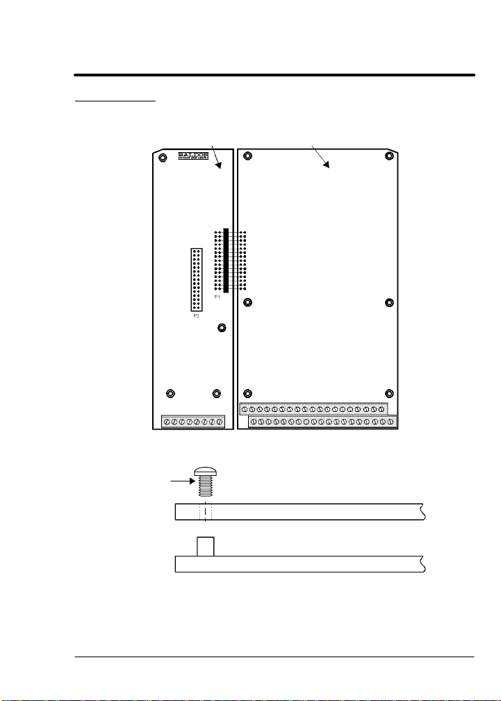
Figure 3-1 Single Expansion Board Installation
Expansion Board Motor Control Board
Terminal tightening torque is 7 lb-in (0.8 Nm) maximum.
Figure 3-2 Single Expansion Board Installation
#6 Screw
Group 1 or 2 Expansion Board
Sheet Metal Mounting Plate
Installation 3-3
Page 13

AC Controls (Continued)
Dual Expansion Board Installation
Procedure:
1. Be sure drive operation is terminated and secured.
2. Remove all power sources from the control.
3. Wait at least 5 minutes for internal capacitors to discharge.
4. Remove the four (4) Phillips head screws (
control cover. (For A & B size, remove four screws that secure the
cover. On floor mounted G size enclosures, open the enclosure
door).
5. Remove the control cover.
6. Slide the Group 1 expansion board male connector into the female
connector of the control board. See Figure 3-1.
7. Securely mount the Group 1 expansion board to the sheet metal
mounting plate using the short standoffs provided in the installation
hardware. See Figure 3-3.
8. The mechanical installation of the expansion board is now
complete. Refer to the manual for the Group 1 board and configure
the jumpers as desired. Also complete the wiring before you
proceed to step 9.
9. Install the Group 2 board on top of the previously installed Group 1
board by plugging the female connector onto the male connector of
the Group 1 board as shown in Figure 3-3.
10. Secure this Group 2 board to the Group 1 board using the #6
screws provided. See Figure 3-3.
11. The mechanical installation of the expansion board is now
complete. Refer to the manual for the Group 2 board and configure
any jumpers and switches as desired. Also complete the wiring for
this board before you install or close the cover.
1
/4 turn) that secure the
3-4 Installation
Page 14
AC Controls
Dual Expansion Board Installation (Continued)
12. When complete, install the control cover using the four (4) Phillips
head screws (
secure the cover. On floor mounted G size enclosures, close the
enclosure door).
13. Restore all power sources to the control.
14. Restore drive operation.
1
/4 turn). (For A & B size, install four screws that
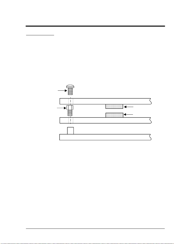
#6 Screw
Short
Aluminum
Standoff
Figure 3-3 Dual Expansion Board Installation
Group 2 Expansion Board
Female Connector
Male Connector
Group 1 Expansion Board
Control Board Mounting Plate
Installation 3-5
Page 15

3-6 Installation
Page 16

Section 4
Hardware Setup
DIP Switch Settings
This procedure will configure the Device Net Expansion Board for
communication with a computer or terminal. Reference Figure 4-1 and
Table 4-1 for the following procedure.
1. Set DIP switches 1 and 2 for the desired baud rate.
2. Set switches 3 through 8 for the ID number desired.
3. Install the Device Net expansion board in the Series H control as
instructed in Section 3 of this manual.
Note: The switch settings can be changed after the board is powered
up. However, switch changes will not take effect until the board
is reset (by pushing PB1 or by turning power off then on).
Cable Connection
1. Connect the Device Net wires to the 5 pin connector provided with
the expansion board as shown in Figure 4-1.
Note: The Device Net bus must provide 24VDC power to the
expansion board.
2. If a terminator is required, connect a 120 ohm terminating resistor
across pins 2 and 4 of the modular connector (CAN– and CAN+).
Powerup
When the Device Net expansion board is powered up it will perform the
following:
1. Perform a self test.
2. Check the switch settings for configuration information.
3. Verify communications with the Series H control board.
4. Check for power on the Device Net bus.
5. Perform a Duplicate MAC ID check to determine if any other
devices on the network have the same MAC ID number.
6. Go online.
After powerup, both LED’s should be GREEN.
Refer to the LED Indicators description in this section of the manual.
Hardware Setup 4-1
Page 17
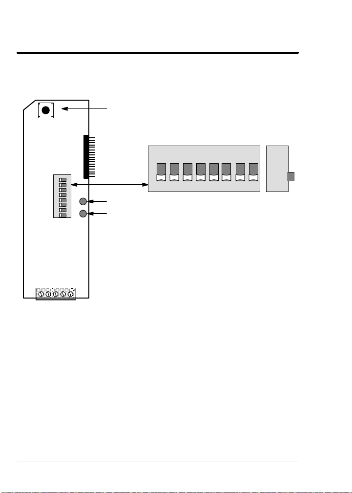
Figure 4-1 Board Configuration
Device Net Expansion Board Catalog No. EXB013A01
P3
12345
V–
(Black)
PB1
12345678
S1
CAN_–
Shield
Shield
CAN_–
(Blue)
(Bare)
ON
MS NS
V+V–CAN_+
V+
CAN_+
(Red)
(White)
Reset switch
All switches shown in OFF position.
ON
12345678
Module Status LED
Network Status LED
Side
View
4-2 Hardware Setup
Page 18

Table 4-1 Switch Settings
Description
125kBPS OFF OFF
250kBPS OFF ON
500kBPS ON OFF
MAC ID 0 OFF OFF OFF OFF OFF OFF
MAC ID 1 OFF OFF OFF OFF OFF ON
MAC ID 2 OFF OFF OFF OFF ON OFF
MAC ID 3 OFF OFF OFF OFF ON ON
MAC ID 4 OFF OFF OFF ON OFF OFF
MAC ID 5 OFF OFF OFF ON OFF ON
MAC ID 6 OFF OFF OFF ON ON OFF
MAC ID 7 OFF OFF OFF ON ON ON
MAC ID 8 OFF OFF ON OFF OFF OFF
MAC ID 9 OFF OFF ON OFF OFF ON
MAC ID 10 OFF OFF ON OFF ON OFF
MAC ID 11 OFF OFF ON OFF ON ON
MAC ID 12 OFF OFF ON ON OFF OFF
MAC ID 13 OFF OFF ON ON OFF ON
MAC ID 14 OFF OFF ON ON ON OFF
MAC ID 15 OFF OFF ON ON ON ON
MAC ID 16 OFF ON OFF OFF OFF OFF
MAC ID 17 OFF ON OFF OFF OFF ON
MAC ID 18 OFF ON OFF OFF ON OFF
MAC ID 19 OFF ON OFF OFF ON ON
MAC ID 20 OFF ON OFF ON OFF OFF
MAC ID 21 OFF ON OFF ON OFF ON
MAC ID 22 OFF ON OFF ON ON OFF
MAC ID 23 OFF ON OFF ON ON ON
MAC ID 24 OFF ON ON OFF OFF OFF
MAC ID 25 OFF ON ON OFF OFF ON
MAC ID 26 OFF ON ON OFF ON OFF
MAC ID 27 OFF ON ON OFF ON ON
MAC ID 28 OFF ON ON ON OFF OFF
MAC ID 29 OFF ON ON ON OFF ON
MAC ID 30 OFF ON ON ON ON OFF
MAC ID 31 OFF ON ON ON ON ON
MAC ID 32 ON OFF OFF OFF OFF OFF
. . . . . . . . . . . . . . . . . . . . . . . . . . .
MAC ID 63 ON ON ON ON ON ON
1 2 3 4 5 6 7 8
Switch Number
Hardware Setup 4-3
Page 19

LED Indicators
Two LED’s are located on the Device net expansion board.
MS - Module Status LED
Displays the operational status of the Device Net Interface expansion
board (EXB). Status is summarized in Table 4-2.
Table 4-2
LED State Status Description
OFF No power is applied to the EXB.
Green The EXB is operating in a normal condition.
Flashing
Green
Red The EXB has an unrecoverable fault and may need to be
Flashing
Red
Flashing
Red-Green
NS - Network Status LED
Displays the status of the connection to the Device Net network. Status
is summarized in Table 4-3.
LED State Status Description
OFF The EXB is not Online or has lost power.
Green The EXB is Online and operating. Link OK, Online, Connected.
Flashing
Green
Red Failed communications tests. EXB detected errors that prevent
Flashing
Red
Flashing
Red-Green
The EXB is in standby mode. The EXB may be attempting to
communicate with the Series H control. Be sure the Series H
control is in RS485BBP mode.
replaced.
The EXB has had a recoverable fault. This may be an invalid
DIP switch setting or the lost Bus Power (Device Net cable
disconnected).
The EXB is in a self test mode.
Table 4-3
EXB is Online but no connection is established. EXB passed
the DUP_MAC_ID test, Online, but has no connections to other
nodes.
it from communicating on the network. Duplicate MAC ID,
Bus-Off.
One or more I/O connections have timed out. Connection timed
out.
The EXB is in a self test mode.
4-4 Hardware Setup
Page 20
Control Terminal Strip Connections
For Serial Mode operation, the Input/Output terminal strip of the control
(J1 of the Vector and DC controls and J4 of the Inverters) is wired as
shown in Figure 4-2. Connect the Enable, Forward Enable Switch,
Reverse Enable Switch, External Trip and Opto Common connections
as shown.
Note: All opto-isolated outputs and analog outputs remain active while
operating in the Serial Mode.
When these connections are complete, refer to Section 5 of this manual
and set the software for Serial Mode.
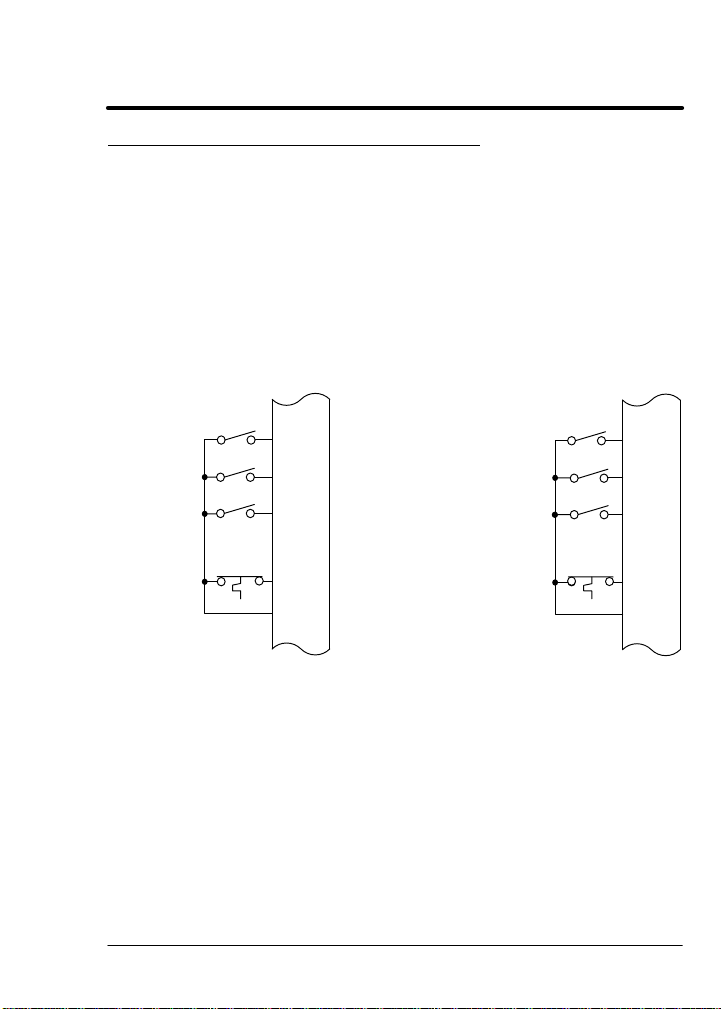
Figure 4-2 Serial Opto Input Connections
J1*
J4**
Enable
Forward
Enable
Reverse
Enable
External
Trip
Common
8
9
10
16
17
* Series 18H, 22H and 23H controls.
** Series 15H and 21H controls.
Enable
Forward
Enable
Reverse
Enable
External
Trip
Common
Hardware Setup 4-5
8
9
10
16
17
Page 21

4-6 Hardware Setup
Page 22

Section 5
Software Setup
Configure Control Software for Device Net Mode
The Series H control operating mode must be set to Serial to use the
Device Net expansion board. There is no selection for Device Net on
the Level 1 Input block Operating mode parameter list. However,
selecting Serial with the Device Net expansion board installed will allow
operation of the Device Net board.
Many commands in the Command Language can be used regardless of
the setting of the control’s Operating Mode parameter (such as
changing and viewing parameters). However, commands intended to
control the motor shaft require the control be in the Serial (Device Net)
Mode.
Note: The firmware version of the Series H control must support the
Baldor Binary Protocol (BBP). To confirm that BBP is supported,
perform the following:
Scroll to the Level 2 Communications block, and view the
selections. If RS485BBP is available, the software version is
compatible with the Device Net expansion board. Otherwise,
contact Baldor to obtain a software update.
During power up, the control checks if the communication board
is installed. If an RS485 board is installed, the RS485BBP
protocol is automatically selected during power up.
Software Setup 5-1
Page 23

Action Description Display Comments
Apply
Power
Display illuminates
BALDOR
MOTORS & DRIVES
Logo is
displayed for 5
seconds.
If no fault is found and
control is programmed for
STP MOTOR SPEED
LOCAL 0RPM
Display mode.
local mode,OR,
If no fault is found and
control is programmed for
STP MOTOR SPEED
REMOTE 0RPM
Display mode.
remote mode
Press
PROG key
Access programming mode.
PRESS ENTER FOR
PRESET SPEEDS
First screen in
programming
mode
Press Y
or B key
Press
Enter key
Press
Enter key
Press Y
or B key
Press
Enter key
Press Y
key
Press
Enter key
Press Y
or B key
Press
Enter key
Scroll to Level 1 Input block
First selection choice
Flashing cursor indicates
mode can be changed
Scroll to Serial mode
Saves mode change value
Scroll to Command Select
parameter
Flashing cursor indicates
mode can be changed
Scroll to Serial mode
Saves change to serial
command select
PRESS ENTER FOR
INPUT
OPERATING MODE
P: KEYPAD
OPERATING MODE
OPERATING MODE
OPERATING MODE
P: SERIAL
COMMAND SELECT
P: +/–10VOLTS
COMMAND SELECT
COMMAND SELECT
COMMAND SELECT
P: SERIAL
KEYPAD
SERIAL
+/–10VOLTS
SERIAL
Input Block.
Now in keypad
mode.
Change to
Serial mode.
Now in ±10 Volt
input mode.
Change to
Serial mode.
Control is now
in Serial mode.
Note: The 15H control does not have a Command Select “Serial”,
this is not needed for this control.
5-2 Software Setup
Page 24

Action Description Display Comments
Press Y
or B key
Press
ENTER
Scroll to Level 2 blocks
Select Level 2 blocks.
PRESS ENTER FOR
LEVEL 2 BLOCKS
PRESS ENTER FOR
OUTPUT LIMITS
First screen in
Level 2 block
key
Press Y
or B key
Press
ENTER
Scroll to Communications
block
Select Level 2
Communications block.
PRESS ENTER FOR
COMMUNICATIONS
PROTOCOL
p: RS232 ASCII
key
Press
Enter key
Press Y
or B key
Press
ENTER
Flashing cursor indicates
mode can be changed
Scroll to RS 485 BBP
(Baldor Binary Protocol)
Select RS 485 BBP mode.
PROTOCOL
RS232ASCII
PROTOCOL
RS485BBP
PROTOCOL
p: RS485BBP
key
Press Y
or B key
Press
DISP key
Press
LOCAL
key
Scroll to Exit Menu
Returns to Display mode.
Changes to Serial
Operation.
PRESS ENTER FOR
MENU EXIT
STP MOTOR SPEED
LOCAL 0RPM
STP MOTOR SPEED
SERIAL 0RPM
Display mode.
Ready for
device net
operation.
The control is now configured for Device Net mode and the Host
software can now be setup.
Software Setup 5-3
Page 25

Device Net Configuration
The Device Net expansion board is a Device Net Group 2 Only Slave
device using the predefined master/slave connection set, as defined by
the ODVA. It is capable of explicit messaging, as well as polled and/or
COS/Cyclic I/O. The interface is based on the Baldor Binary Protocol
(BBP) command set.
This EDS file (Electronic Data Sheets) is used by Device Net equipment
to communicate with the BBP of the Baldor Device Net expansion
board. The Baldor EDS file is provided on a diskette that is shipped with
the expansion board. A Device Net configuration tool, such as
Allen-Bradley “Device Net Manager” software should be used to
configure the Device Net expansion board. The EDS file is also
available on the Baldor World Wide WEB page (www.baldor.com).
EXB I/O Instances
The input and output assembly instances are predefined I/O data
formats that can be selected based on your application. If an I/O
connection is being used, the selected I/O assembly instance
determines the size and format of the data. Only one input instance and
one output instance can be selected. The Input and Output instances
should be set using a Device Net configuration tool prior to connection
to a host device.
Note: Instances 105 and 155 are factory preset. These instances must
be properly set for your application.
Elements of an I/O instance can be 1 to 32 bits in length and can
reference any of the Baldor Binary Protocol (BBP) transactions
supported by the Device Net expansion board (see Section 6 of
this manual). Each assembly instance can contain no more than
8 bytes.
Tables 5-1 and 5-2 defines the format of the Input and Output Assembly
Instances.
5-4 Software Setup
Page 26

# Byte
151
152
Table 5-1 Format of Input Assembly Instances
Bit7 Bit6 Bit5 Bit4 Bit3 Bit2 Bit1 Bit0
0
1
ControlState Warning Output1 Output2 Output3 Output4
T#4 T#27 TerminalStrip T#31
CommandMode network remote rev fwd
2
3
4
5
0
1
2
3
ZeroSpd AtSpeed Input 4 Input 5 Input 6 Input 7 Input 8 Input 9
4
T#25 T#26 TerminalStrip T#31
5
MotorDir ControlState Output1 Output2 Output3 Output4
6
T#24 T#4 TerminalStrip T#31
7
CommandMode network remote rev fwd
Instance Byte Format
T#5 CtrlSourceT#3 RunCMDT#1
SpeedActual T#18 (Low Byte)
SpeedActual T#18 (High Byte)
CurrentActual T#17 (Low Byte)
CurrentActual T#17 (High Byte)
SpeedActual T#18 (Low Byte)
SpeedActual T#18 (High Byte)
CurrentActual T#17 (Low Byte)
CurrentActual T#17 (High Byte)
FaultStatus T#45
T#5 CtrlSourceT#3 RunCMDT#1
Software Setup 5-5
Page 27

# Byte
153
154
Table 5-1 Format of Input Assembly Instances Continued
Bit7 Bit6 Bit5 Bit4 Bit3 Bit2 Bit1 Bit0
0
1
2
3
4
5
0
1
2
3
4 Position T#15 (Low Word/Low Byte)
5 Position T#15 (Low Word/High Byte)
6 Position T#15 (High Word/Low Byte)
7 Position T#15 (High Word/High Byte)
ControlState
T#4 T#27 TerminalStrip T#31
CommandMode network remote rev fwd
Input6 Input7 Input8 Input9 Output1 Output2 Output3 Output4
CommandMode network remote rev fwd
Instance Byte Format
Warning
Output1 Output2 Output3 Output4
T#5 CtrlSourceT#3 RunCMDT#1
FreqActual T#19 (Low Byte)
CurrentActual T#17 (Low Byte)
CurrentActual T#17 (High Byte)
TerminalStrip T#31
T#5 CtrlSourceT#3 RunCMDT#1
SpeedActual T#18 (Low Byte)
SpeedActual T#18 (High Byte)
Note: For Table 5-2, use instance 103 for 15H and 21H controls (speed
is sent in Hertz). Use other instances for 18H, 22H and 23H
(speed is sent in RPM).
5-6 Software Setup
Page 28

Table 5-2 Format of Output Assembly Instances
# Byte
101
102
103
104
Bit7 Bit6 Bit5 Bit4 Bit3 Bit2 Bit1 Bit0
FaultRst RunInhibit TableSelect Output1 Output2 Output3 Output4
0
T#46 T#2 T#39 T#75
1
2 (RPM) SpeedRef T#7 (Low Byte)
3 (RPM) SpeedRef T#7 (High Byte)
4 TorqueRef T#9 (Low Byte)
5 TorqueRef T#9 (High Byte)
0 SpeedRef T#7 or PositionSpeed T#13 Low Byte
1 SpeedRef T#7 or PositionSpeed T#13 High Byte
2 TorqueRef T#9 or TorqueRef T#12 Low Word, Low Byte
3 TorqueRef T#9 or TorqueRef T#12 Low Word, High Byte
4 TorqueRef T#9 or TorqueRef T#12 High Word, Low Byte
5 TorqueRef T#9 or TorqueRef T#12 High Word, High Byte
FaultRst ZeroPos AccDecGroup Output1 Output2 Output3 Output4
6
T#46 T#12 T#40 T#75
7
FaultRst RunInhibit TableSelect Output1 Output2 Output3 Output4
0
T#46 T#2 T#39 T#75
1
2 (0.1Hz) HzSpeedRef T#6 (Low Byte)
3 (0.1Hz) HzSpeedRef T#6 (High Byte)
4 TorqueRef T#9 (Low Byte)
5 TorqueRef T#9 (High Byte)
FaultRst ZeroPos TableSelect Output1 Output2 Output3 Output4
0
T#46 T#12 T#39 T#75
1
2 PositionSpeed T#13 (Low Byte)
3 PositionSpeed T#13 (High Byte)
4 PositionRef T#12 (Low Word/Low Byte)
5 PositionRef T#12 (Low Word/High Byte)
6 PositionRef T#12 (High Word/Low Byte)
7 PositionRef T#12 (High Word/High Byte)
CommandMode network remote rev fwd
T#5 CtrlSourceT#3 RunCMDT#1
CommandMode network remote rev fwd
T#5 CtrlSourceT#3 RunCMDT#1
CommandMode network remote rev fwd
T#5 CtrlSourceT#3 RunCMDT#1
CommandMode network remote rev fwd
T#5 CtrlSourceT#3 RunCMDT#1
Instance Byte Format
See notes on next page.
Software Setup 5-7
Page 29

Notes:
Used with CommandMode (T#5). These bytes represent the variables
SpeedRef (T#7), or Position SpeedRef (T#13).
Used with CommandMode (T#5). These bytes represent the variables
TorqueRef or PositionRef. PositionRef requires 4 bytes. TorqueRef
requires 2 bytes (Low Word).
TableSelect is not implemented at this time.
When a PLC updates memory in the middle of a double integer write of
PositionRef, a problem may occur. If the first integer is written and the
PLC updates the memory of a networked device, the position information
is wrong (second integer is missing). To avoid this problem, be sure the
CommandMode (T#5) is not set to PositionCmd until after both integers
are written.
Torque and Position commands are not implemented for the Series 15H
Control.
5-8 Software Setup
Page 30

Section 6
Command Language
Transaction Specification
This section contains a detailed list of the transactions currently
supported by the protocol. The list includes the transaction
number, name, type description, and a detailed specification of
the required and returned data.
Note: Some transactions are not supported by all control types.
Also some controls require variations in commanded data.
Where these exceptions exist, they will be identified in the
text.
How To Read The Transaction Specification
The transaction table provides quick access to relevant
information about each transaction. When necessary a
transaction will be explained in more detail in the sections that
follow.
Transaction Number (T#)
The transaction number is the identification of the command. As
mentioned in Section 3, the maximum number of transactions is
256 (250 – 255 are reserved for future use.)
Command Language 6-1
Page 31

Name
The ‘Name’ field refers to a ‘C’ style variable for function names
associated with the transaction. Use of these names is not
necessary to interface with the transaction. These names may
be used in present and future software drivers and libraries
provided by Baldor. When used in conjunction with Baldor
software tools, the transaction name is case sensitive.
Type
There are three basic transaction types: Set, Get, and those
which do both: Set/Get.
S ‘Set’ transactions are used to change internal values, or
execute one–time (nonmodal) commands. As a general rule
most ‘set’ transactions pass data to the control, but do not
return any. Most execution ‘set’ commands do not pass or
return data.
S ‘Get’ transactions are used to retrieve internal values or
control conditions. Most ‘get’ transactions return data but do
not pass data.
S ‘Set/Get’ transactions do both functions. Usually these
transaction always return data, but only accept or pass data
when a ‘set’ or change function is occurring. When no data is
passed, the ‘Set/Get’ functions as a ‘Get’ or read–only
transaction.
When a transaction does not fit these general rules, both passed
and returned data fields will be clearly specified.
6-2 Command Language
Page 32

Data Field
The Data Field defines the data transfer requirements of the
application layer message. This field describes the data using
the ‘data type’ defined in Section 2.l. Commas separate
individual elements of data.
As previously discussed in Section 3, there are two types of
application layer packets–. Command and Response.
Command packets ALWAYS contain a transaction number
(USINT). Response packets ALWAYS contain a transaction
number (USINT) and a status (USINT). The transaction
specification is only concerned with the data field portion of these
messages. The transaction number and status are assumed to
be present, and are not shown in the specification.
In transactions that fit the basic Set, Get, and Set/Get definitions,
only a single data field is described in the specification. In these
cases it is assumed that a ‘Set’ transaction has only Command
packet data. A ‘Get’ has only Response packet data. And a
‘Set/Get’ has the same data in the Command and Response
packet, unless it is being used to ‘Get’ only, in which case there
is no Command data.
Transactions are not required to conform to these basic rules.
When such exceptions exist, both their Command and Response
data fields will be described in detail. The command data field is
preceded by a C:, the response data field is preceded by a R: for
identification purposes only.
In some cases variable names are given in the data field
specification. These names are used to describe multiple
elements of a common data type. These names are not required
for use, but may be included in present and future software
drivers and libraries provided by Baldor. (When used with tools
provided by Baldor, variable names are case sensitive.)
Command Language 6-3
Page 33

Class
The class field indicates the product classes that support the
transaction. The product codes are as follows:
E = Encoderless Vector
I = Inverter
S = Servo
V = Vector
V* = Vector with custom software for positioning
Description
The description field gives information regarding the use of the
transaction. When possible the data range, scale, units, etc. are
also given. When it is not possible to fully describe the
transaction in the table, or when other information such as a
state diagram or event matrix must be given, further information
will be included in sections following the transaction table. An
asterisk is used to indicate default power up values where
applicable.
6-4 Command Language
Page 34

Transaction Specification Table
Table 6-1 Transaction Specification Table
T# Name Type Data Field Class Description
0 Null Set None All No action.
1 RunCmd Set/
2 RunInhibit Set/
USINT All Network run / stop
Get
BOOL All Commands a stop
Get
This can be used to
reset the watchdog
timer, or as a
placeholder in
conjunction with a
global Execute
Buffer transaction.
command. Get 0 =
Stop (refer to stop
mode parameter)
1 = Fwd
2 = Rev
3 = Bipolar Run *
Actual motor
direction is returned
in Motor Direction. In
fwd or rev, only the
absolute value of the
command
references (speed,
torque) are used. In
bipolar run, the
signed reference
values control the
direction. These
commands are only
valid when
CtrlSource = 2
(control from
network)
regardless of the
command source
(Local Keypad,
Remote terminal
strip, control from
network.)
1 = Stop, 0 = No
action*
* Indicates initial powerup value.
Command Language 6-5
Page 35

Table 6-1 Transaction Specification Table Continued
T# Name Type Data Field Class Description
3 CtrlSource Set USINT All 0 = Keypad (local)
4 ControlState Get USINT E,V,S 0 = Not Ready (no
5 CommandMode Set/
USINT All Command Mode
Get
1 = Terminal strip
(remote)
2 = Control from
network
main power)
1 = Ready (disabled)
2 = Enabled
3 = Stopping
4 = Fault exists
0 = None (Disabled) *
1 = Torque CMD
selected
source
2 = Torque CMD
network
3 = Speed CMD
selected
source
4 = Speed CMD
network
5 = Orient
6 = Position CMD ABS
7 = Position CMD INC
9 = Position CMD
external
10 = Home
11 = Process Torque
12 = Process Speed
13 = Auto Tune
Refer to the command
mode section for
complete operational
description.
* Indicates initial powerup value.
6-6 Command Language
Page 36

Table 6-1 Transaction Specification Table Continued
T# Name Type Data Field Class Description
6 HzSpeedRef Set/
7 SpeedRef Set/
8 SpeedRefHigh Set/
9 TorqueRef Set/
12 PositionRef Set/
13 PositionSpeed Set/
15 Position Set/
INT
Get
INT
INT
Get
INT
DINT E,S,V Speed reference
Get
INT S,V Torque reference
Get
DINT S, V* Position Reference
Get
INT S, V* Positioning Speed
Get
DINT S, V* Position counter
Get
I,
All
E,V,S,
All
Hertz Speed
Reference.
Set Units: 0.1 Hz
(one decimal place)
Speed reference
Units: RPM
(Standard Get
Resolution)
(High Resolution)
Units: 1/256 RPM .
The middle 16 bits
mirror SpeedRef.
Not supported by all
product classes.
(Current)
Scaling: ±15bit
(32767) =
programmed current
limit.
Scaling = quadrature
counts (4 x
feedback counts per
rev.)
Reference
Max speed used for
positioning
commands. Also
referred to as feed
rate or target
velocity.
Units: RPM
Scaling = quadrature
V* = Vector with custom software for positioning
Command Language 6-7
Page 37

Table 6-1 Transaction Specification Table Continued
T# Name Type Data Field Class Description
17 CurrentActual Get INT E,I,S,VActual motor phase
18 SpeedActual Get INT All Actual motor speed
19 FrequencyActual Get INT E,I,S,VActual motor
20 PowerActual Get INT E,V,S Actual output power
21 InputVoltage Get INT E,V,S Input line voltage
22 OutputVoltage Get INT E,V,S Motor phase voltage
24 MotorDirection Get BOOL E,V,S 0 = Fwd
25 ZeroSpeed Get BOOL E,S,V 1 = At zero
26 AtSpeed Get BOOL E,V,S 1 = At commanded
27 Warning Get BOOL E,V,S 1 = Warning
current
Units: 100mA RMS
Note: calculated on
inverter.
(absolute value.)
(Approximated in
some products.)
Units: RPM
frequency Units: 0.1
Hz (one decimal
place)
Units: Watts
Units: Volts RMS
(commanded)
Units: Volts RMS
1 = Rev
Actual in position
feedback products,
commanded in
others.
0 = Not at zero
speed
0 = Not at speed
0 = No warnings
present
* Indicates initial powerup value.
6-8 Command Language
Page 38

Table 6-1 Transaction Specification Table Continued
T# Name Type Data Field Class Description
28 AtPosition Get BOOL S,V 1 = At position
29 AtSetpoint Get BOOL E,V,S 1 = At setpoint
30 AtSetSpeed Get BOOL E,V,S 1 = At set speed
31 TerminalStrip Get WORD All Digital I/O status
32 SoftwareVersion Get STRING E,V,S Control software
33 SoftwareRevision Get UINT All Control software
34 ProductSeries Get UINT All Product series for
35 ProductClass Get USINT All 0 = D
36 Optionld1 Get USINT E,V,S Option ID1 (see
37 Optionld2 Get USINT E,V,S Option ID2 (see
0 = Not at position
0 = Not at setpoint
0 = Not at set speed
word. Refer to Table
6-3 for description.
version (16
characters
maximum.)
revision number. For
example S15–4.03 is
returned as 403.
Note: for custom
software revisions,
only the core
(standard) revision is
returned.
example a Series
15H returns: 15.
1 = DP
2 = E
3 = I
4 = S
5 = V
table 6-4)
0 = Not installed
table 6-4)
0 = Not installed
* Indicates initial powerup value.
Command Language 6-9
Page 39

Table 6-1 Transaction Specification Table Continued
T# Name Type Data Field Class Description
38 RunTime Get UDINT E,V,S Total time power has
39 TableSelect Get/
40 AccDecGroup Get/
41 WatchdogTime Get/
45 FaultStatus Get USINT All Request current fault
USINT E,S,V Parameter table
Set
USINT E,V,S Accel / decel group
Set
UINT All Network watchdog
Set
been applied. Units:
seconds.
select
Range 0 – 3
Note: DDC only
supports 2 tables.
Can only be
changed when under
network control
select
Range 1 – 2 Can
only be changed
when under network
control.
timer Get Units:
10mS
0 = disable
2= 20mS minimum
6000= 60S
maximum
Note: resolution
varies among
product classes.
condition
0 = No fault
1–xx = Current fault
code (See H Series
– Fault Message
Description table at
the end of this
section for
description.)
* Indicates initial powerup value.
6-10 Command Language
Page 40

Table 6-1 Transaction Specification Table Continued
T# Name Type Data Field Class Description
46 FaultRst Set BOOL All 1 = Execute fault
47 FaultLog Get C: USINT
FaultLogInde
x
R: UINT
FaultCode,
UDINT
TimeStamp
48 FaultCodeText Get C: USINT
FaultCode
R: STRING
FaultText
49 ForceFault Set BOOL All 0->1 =Force Network
50 SecurityStatus Get USINT All Requests network
reset
0 = No action
Clears any active
fault condition.
Operation resumes
at previous
command.
All Requests the
FaultCode and
TimeStamp for the
given index. The
fault log holds the
last 31 fault
conditions (1 being
most recent) The log
will return a 0 for the
code and time stamp
if the specified index
is empty. Time
stamp is in seconds.
All Returns the text
string associated
with the FaultCode.
16 characters
maximum.
Fault
0 = No action
security status.
0 = Security disabled
1 = Security
unlocked
2 = Security locked
* Indicates initial powerup value.
Command Language 6-11
Page 41

Table 6-1 Transaction Specification Table Continued
T# Name Type Data Field Class Description
51 SecurityLock Set INT or
NONE
52 CalcPresets Set BOOL E,S,V This transaction is
56 BlockStructure Get USINT
Level1Max,
Level2Max,
Level3Max,
57 BlockDetail Get C: USINT
Level, Block
R: USINT
MaxParams,
STRING
BlockName
All Unlocks or locks
network parameter
security. Passing the
valid SecurityCode
unlocks parameter
access. Any other
value (including
NONE) locks
parameter access.
used during setup to
calculate initial
values for tuning and
performance
parameters based
on motor nameplate
values. Note: this
command is not valid
for all product
classes.
1 = Execute preset
calculation
0 = No action
All Returns the number
of blocks on each
programming level.
Assumes a max of
three programming
levels.
All Returns the number
of parameters in the
block and the
BlockName (16
characters max.)
* Indicates initial powerup value.
6-12 Command Language
Page 42

Table 6-1 Transaction Specification Table Continued
T# Name Type Data Field Class Description
58 BlockParamDetail Get C: USINT
Level, Block,
Index
R: INT
Pnum,
Pvalue,
Pmin, Pmax,
Pdlft, Pprec,
Ptype,
STRING
Pname,
Punits
59 ParameterDetail Get C: INT
Pnum,
R: INT
Pnum,
Pvalue,
Pmin, Pmax,
Pdlft, Pprec,
Ptype,
STRING
Pname,
Punits
60 ParameterList Get C: INT
Pnum,
ListIndex
R: STRING
ListText
All Returns full
parameter detail
information for the
parameter specified
at the given Level,
Block and index.
All Returns full
parameter detail
information for the
given Pnum.
All Returns the
enumerated list
string for the given
parameter number
and list index. 16
characters max. If
ListIndex exceeds
the number of
elements an ‘end of
block’ status will be
returned. (Note: Use
Pmax to determine
the end of the list.)
* Indicates initial powerup value.
Command Language 6-13
Page 43

Table 6-1 Transaction Specification Table Continued
T# Name Type Data Field Class Description
61 ParameterValue Set/
62 BatchSend Get C: INT
63 BatchRcv Set INT
64 FactorySettings Set BOOL All 1 = Reset all
Get
C: INT
Pnum,
Pvalue
R: INT
Pvalue
(excluding
Pvalue from
CMD
indicates
request only).
GroupNumbe
r
R: INT
PnumN,
PvalueN, ...
N=16
PnumN,
PvalueN, ...
N=16
All Change / request
value of specified
user parameter.
Returned value will
give actual, after any
bounds checking.
Refer to the control
manual for
description.
All Batch transfer that
returns raw (data
only) from control to
host. Up to 16
parameters are sent
at a time. Last group
will be truncated if
necessary. Group
numbers start at 0. If
the GroupNumber
exceeds the number
of blocks an ‘end of
block’ status is
returned. The control
must be disabled.
All Block transfer that
accepts raw
parameter (data
only) from host to
control. Up to 16
parameters may be
sent at a time.
Parameters may be
sent in any order.
The control must be
disabled.
parameters to
factory settings.
0 = No action
* Indicates initial powerup value.
6-14 Command Language
Page 44

Table 6-1 Transaction Specification Table Continued
T# Name Type Data Field Class Description
69 ClearAll Set USINT All Reserved for factory
70 LogClear Set USINT All Reserved for factory
71 AnalogInput1 Get UINT All
72 AnalogInput2 Get UINT All
73 SetAnalogOut1 Set INT All
74 SetAnalogOut2 Set INT All
75 SetDigitalOut Set BYTE All Commands the
76 GetDebugVal Get C: INT
MemLoc
R: INT Value
use.
use.
Reads the raw value
of the A/D
converters on the
control. Update rate
control. Update rate
and resolution vary
per control. Unused
MSBs will be padded
with zero.
Commands the
DACs on the control,
and/or option card.
Analog output
parameter must be
set to Serial to be
valid. (Note 8 bit
DACs will only use
the upper byte.)
digital outputs on the
control, and/or option
card. Only lowest
four bits are used.
The LSB
corresponds to opto
out #4. The opto
output parameter
must be set to serial
to be valid.
All Reserved for factory
use.
* Indicates initial powerup value.
Command Language 6-15
Page 45

Table 6-1 Transaction Specification Table Continued
T# Name Type Data Field Class Description
250 Reserved for future
251 Reserved for future
252 Reserved for future
253 Reserved for future
254 Reserved for future
255 Reserved for future
use.
use.
use.
use.
use.
use.
6-16 Command Language
Page 46

5 - Command Mode
Command
5 USINT CommandMode
Response
5 ST USINT CommandMode
Type: Set/Get
This transaction changes the command mode of the Series H
control. The command mode is an 8–bit value. Loading the
appropriate value into the command mode register activates the
appropriate operating mode. Only one mode can be selected at
a time. Table 6-2 provides a description of the possible command
modes.
Initial Condition:
At powerup, the command mode is set to 00H (disabled).
Command Language 6-17
Page 47

Table 6-2 Command Mode Table
Value Mode Class Description
0 None ALL No mode selected. Output stage of
1 Torque CMD
selected source
2 Torque CMD
Network
3 Speed CMD
selected source
4 Speed CMD
Network
5 Orient S,V C or Index channel orient. The motor will
6 Position CMD
ABS
7 Position CMD
INC
9 Position CMD
External
11 Process Torque All Closes the torque process control loop.
12 Process Velocity All Closes the velocity process control loop.
control remains off or disabled (voltage
and current removed from the motor),
regardless of RunCmd condition.
S,V Closes the current loop with command
input from the source selected in the
COMMAND SELECT parameter.
S,V Closes the current loop with command
input from the TorqueRef register.
All Closes the velocity loop with command
input from the source selected in the
COMMAND SELECT parameter.
All Closes the velocity loop with command
input from the SpeedRef register.
be commanded in the Fwd direction at
the predefined homing speed until the
index pulse is detected. The motor will
then be commanded to hold position at
the predefined home offset.
S,V Closes the position loop with an absolute
position command from the PositionRef
register.
S,V Closes the position loop with an
incremental position command from the
PositionRef register.
S,V Closes the position loop with command
input from external option source (such
as pulse follower EXB card.)
Commands come from the appropriate
command input parameters.
Commands come from the appropriate
command input parameters.
6-18 Command Language
Page 48

31- TerminalStrip
Command
31
Response
31 ST WORD TerminalStrip
Type: Get
This transaction returns a bit–wise word representing the status
of the control digital inputs and outputs.
Table 6-3 provides a description of the codes.
Note: A bit value of 1=closed or ON, 0=open or OFF.
Table 6-3 TerminalStrip Table
Bit Name Typical Single-Axis
Location
0 Output4 J1 (J4) - 22 J1B - 13
1 Output3 J1 (J4) - 21 J1B - 12
2 Output2 J1 (J4) - 20 J1B - 11
3 Output1 J1 (J4) - 19 J1B - 10
4 Input9 J1 (J4) - 16 J1B - 9
5 Input8 J1 (J4) - 15 J1B - 8
6 Input7 J1 (J4) - 14 J1B - 7
7 Input6 J1 (J4) - 13 J1B - 6
8 Input5 J1 (J4) - 12 J1B - 5
9 Input4 J1 (J4) - 11 J1B - 4
10 Input3 J1 (J4) - 10 J1B - 3
11 Input2 J1 (J4) - 9 J1B - 2
12 Input1 J1 (J4) - 8 J1B - 1
13 Not Used
14 Not Used
15 Not Used
Typical Multi-Axis
Location
Note: J1 = for Vector Controls, J4 = for Inverter Controls.
Command Language 6-19
Page 49

36 or 37 - Optionald#
Command
36
Response
36 ST USINT Optionld
Type: Get
This transaction returns the id number for the option installed in
the specified location.
Table 6-4 provides a description of the possible values.
Table 6-4 Optionald# Table
ID EXB No. EXB Name Group
1 EXB001A01 RS232 Serial Communications 2
2 EXB002A01 RS422/485 Serial Communications 2
3 EXB003A01 Isolated Input 1
4 EXB004A01 4 Output Relays / 3-15 PSI Pneumatic 2
5 EXB005A01 Master Pulse Reference/Isolated Pulse
Follower
6 EXB006A01 DC Tachometer 1
7 EXB007A01 High Resolution Analog I/O 2
8 EXB008A01 Isolated Encoder 1
9 EXB009A01 Resolver to Digital 1
10 EXB010A01 2 Isolated Analog Output / 3 Relay 2
11 EXB012A00 RS232/485 Serial Communications 2
1
6-20 Command Language
Page 50

41 - WatchdogTime
Command
41 UINT WatchdogTime
Response
41 ST UINT WatchdogT ime
Type: Set/Get
This transaction is used to change the value of the network
watchdog timer. The value is entered in milliseconds (mS). The
watchdog timer is used to detect a communications loss. When
the time between network commands exceeds the value stored
in this register, a fault is generated and the control is disabled.
Each time a network command is received, the internal timer is
reset to zero. The host must continuously send commands to
keep the timer reset. If desired a NULL transaction can be used
to reset the timer. Setting the timer to zero disables this function.
The minimum time value (other than zero) is 20mS (2). The
maximum value is 60S (6000). Resolution varies among product
classes.
Scale/ Units: 10mS
ParameterDetails
Table 6-5 describes the data that is returned during a parameter detail
response.
Command Language 6-21
Page 51

Table 6-5 ParameterDetails Table
Field Name Description
INT Pmin Parameter minimum allowed value.
INT Pmax Parameter maximum allowed value. (Number of list items
INT Pdflt Parameter default value (factory) value.
USINT Pprec Indicates the number of decimal places to use for the
BYTE Ptype Returns bit–wise parameter type.
STRING Pname Returns string representing parameter name. For example
STRING Punits Returns the parameter engineering units string. Max
in an enumerated type parameter.)
parameter value.
Bit 0 = Numeric parameter
Bit 1 = Enumerated list parameter
Bit 2 = Can be changed while enabled
Bit 3 = Default from calculation
Bit 4 = Not set during ‘restore to factory’
Bit 5 = Signed parameter
“Preset Speed #1”. Max number of characters is 16.
number of characters is 4.
6-22 Command Language
Page 52

H Series – Fault Message Description
Fault Message
Line Regen 1 1 Fault in Line REGEN converter unit -
Feedback Fault 2 Loss of encoder feedback.
Invalid Base ID 3 3 Failed to read configuration from the Power
Low INIT Bus V 4 4 Low bus voltage detected on start–up.
Regen Res
Power
Current SENS
FLT
HW
Desaturation
HW Ground
Fault
Resolver Fault 9 Loss of resolv er feedbac k .
HW Power
Supply
Overcurrent 11 11 Continuous current limit exceeded.
Bus
Overvoltage
Following ERR 13 Mot or speed/pos ition does not follow comm and.
Torque Prove 14 Unbalanced current between all 3 phases.
Bus
Undervoltage
3 Sec Overload 16 16 Peak output current exceeded the 3 second
Over Speed 17 Motor RPM exceeded 110% of MAX Speed.
Motor Temp 18 Motor over temperature
Heatsink Temp 19 19 Control heatsink exceeded temperature limit.
External Trip 18 20 Connection at J1/J4 pin 16 and 17 is open.
Param
Checksum
Fault Code
15H 18H
Series 21H Line REGEN Inverter control.
Base ID value in software.
5 5 Excessive power dissipation required by
6 6 Failure to sense phase current.
7 7 High output current condition detected (greater
8 8 Ground Fault detected (output current leakage
10 10 Control Board power supply failure detected.
12 12 High DC Bus voltage.
15 15 Low DC Bus voltage condition detected.
51 21 Parameter checksum error.
Dynamic Brake Hardware.
than 400% of rated output current).
to ground).
rating value.
Fault Description
Command Language 6-23
Page 53

H Series – Fault Message Description Continued
Fault Message
µp Reset 22 22 A software watchdog timer has reset the
ROM Fault 23 ROM checksum error.
1 Min Overload 24 24 Peak output current exceeded the 1 minute
No I Feedback 25 Loss of current feedbac k
New Base ID 26 26 Control board detected a change in the Power
EXB Selection 27 27 Expansion board not installed to support the
Power module 28 Power module failure.
Co–processor 29 Co–processor error (i.e. DSP board).
Software
Version
Feedback
Module
Serial watchdog 32 Serial port transmit/receive error
FLT Network 33 33 Lost network com m unicat ions .
Hardware
Protect
Unknown FLT
Code
Bus Current
SENS
Fault Code
15H 18H
processor because a process has timed out.
rating value.
Base ID value in software.
Level 1 Input Block, Command Select
parameter.
30 Wrong control software version detected.
31 Feedback HW module failure.
54 A general hardware fault was detected but
55 34 Microprocessor detected a fault that is not
56 Failure to sense bus current.
cannot be isolated.
identified in the fault code table.
Fault Description
Note These faults may be different for custom software.
6-24 Command Language
Page 54

BALDOR ELECTRIC COMPANY
P.O. Box 2400
Fort Smith, AR 72902–2400
(479) 646–4711
Fax (479) 648–5792
Baldor Electric Company Printed in USA
MN1320 8/03 C&J500
 Loading...