

Page 1

DTM8000
Digital Tachometer
Installation and Operating Manual
LT49 (A-5-3196A) MN1327
Page 2

Quick Jump
What models and recommended accessories are
available?
See page 3.
Looking for detailed specifications?
See page 3.
Want to get started fast?
See basic electrical hook-up details on page 5.
See mechanical installation details on page 4.
See some sample applications starting on page 15.
Need Help?
See troubleshooting on page 19.
LIMITED WARRANTY
For a period of one (1) year from the date of original purchase, BALDOR will repair or replace without charge controls
and accessories which our examination proves to be defective in material or workmanship. This warranty is valid if
the unit has not been tampered with by unauthorized persons, misused, abused, or improperly installed and has been
used in accordance with the instructions and/or ratings supplied. This warranty is in lieu of any other warranty or
guarantee expressed or implied. BALDOR shall not be held responsible for any expense (including installation and
removal), inconvenience, or consequential damage, including injury to any person or property caused by items of our
manufacture or sale. (Some states do not allow exclusion or limitation of incidental or consequential damages, so
the above exclusion may not apply.) In any event, BALDORs total liability, under all circumstances, shall not exceed
the full purchase price of the control. Claims for purchase price refunds, repairs, or replacements must be referred
to BALDOR with all pertinent data as to the defect, the date purchased, the task performed by the control, and the
problem encountered. No liability is assumed for expendable items such as fuses.
Goods may be returned only with written notification including a BALDOR Return Authorization Number and any return
shipments must be prepaid.
WARNING
Improper installation or operation of this control may cause injury to personnel or control failure. The control must be
installed in accordance with local, state, and national safety codes. Make certain that the power supply is disconnected
before attempting to service or remove any components!!! If the power disconnect point is out of sight, lock it in
disconnected position and tag to prevent unexpected application of power. Only a qualified electrician or service
personnel should perform any electrical troubleshooting or maintenance. At no time should circuit continuity be
checked by shorting terminals with a screwdriver or other metal device.
Page 3

Table of Contents
Introduction .......................................................................................................................................2
General Features ..............................................................................................................................2
Models & Options .............................................................................................................................3
Model Table ....................................................................................................................................3
Recommended Accessories .........................................................................................................3
Specifications....................................................................................................................................3
Electrical........................................................................................................................................3
Mechanical .................................................................................................................................... 3
Environmental ...............................................................................................................................3
Mechanical Installation .....................................................................................................................4
Exploded Panel View .....................................................................................................................4
Cut-out and Mounting Dimensions ................................................................................................4
Electrical Installation & Diagrams ...................................................................................................5
P1 Terminal Block Wiring Diagram ...............................................................................................5
P1 Terminal Block Descriptions ....................................................................................................5
Basic Operating Instructions ..........................................................................................................6
Rate, Time, and Counter Modes Explained ................................................................................... 6
Visual Reference ...........................................................................................................................6
How to Change a Parameter's Value (The Short Story) ................................................................6
Operating the User Interface (The Long Story) .............................................................................. 6
Detailed Configuration Instructions ...............................................................................................7
Factory Set Configuration .............................................................................................................. 7
Resetting the Unit to Factory Settings ...........................................................................................7
JP1 (Program Enable Jumper) ...................................................................................................... 7
Software Parameters ....................................................................................................................8
Parameter Descriptions .............................................................................................................. 10
Application Examples ..................................................................................................................... 15
Pump Flow Monitor with Audible and Visual Alarm ...................................................................... 15
Conveyor Oven Time Monitor with Over-Heating Alarm .............................................................. 16
Take-up / Pay-out Reel Material Measurement with Alarm........................................................... 17
Bi-directional Incremental Position Display ................................................................................. 18
Troubleshooting ............................................................................................................................. 19
1
Page 4

Introduction
The DTM8000 Digital Meter is a powerful, microprocessor-based unit capable of being configured for
a number of todays demanding measurement needs. It can be quickly configured to operate as a digital
rate meter, timer, or feature-filled process counter. It also offers up to two alarm outputs which can be
adjusted for a number of trigger conditions. Its durable 1/8DIN aluminum housing can be easily mounted
in a panel or control cabinet. Flexibility makes the DTM8000 ideal for applications such as:
Pay-out and Take-up Limit Monitors
Conveyor Oven Tunnel-Time Monitors
Rotating Machinery Tachometers
Material Measurement Meters
General Features
- Microprocessor-based design combines responsiveness and accuracy in one package
- Selectable display update rate
- Capable of measuring shaft speeds lower than 1 RPM @ 1 pulse per revolution
- Large 4 digit, ½ LED display
- Field programmable via front-panel keypad
- Lexan membrane and gasket (which are included) meet NEMA 4X standards when used with NEMA
4X enclosures
- Internal program-enable jumper selectively prevents tampering with units configuration
- Universal power supply accepts line voltages inputs from 85-265VAC @ 50-60Hz without switches
or jumpers. The unit automatically adjusts as needed.
- Non-volatile memory stores adjustable parameters even when power has been removed
- Compatible with a variety of signal input types including: Hall-Effect Pickups, Photoelectric, TTL, etc.
Note: Open collector devices must be capable of sinking 3mA.
- Wide operating ambient temperature range of -10C to 45C (14F to 113F)
- Self-contained power supply for external sensor, limited to 5V @ 50mA
- Up to 2 programmable alarm outputs with Form C contacts rated to 250VAC @ 5A
- Multiple auto-ranging features allow the user to view display values from 0.001 to 99,990 in any userdefined unit. (GPH, MPH, RPM, etc.)
- Multiple operating modes including:
Rate Mode Displays in rate unit such as RPM, Gallons per Second, etc.
Time Mode Displays in time unit such as HH:MM, MM:SS, SS:TT, or other unit
Counter Modes Displays resettable and reloadable counter value which can optionally
increment or decrement for each input pulse. Quadrature inputs can automatically
be translated to up/down counts for bidirectional applications
2
Page 5
Model Table
Models & Options
Model
DTM8000-6 85-265VAC 1 Yes Yes Yes Yes Yes
Input Voltage
Outputs
Alarm
Measures
Rate?
Measures
Time?
Up
Counter?
Down
Counter?
Quadrature
Compatible?
Encoder
Recommended Accessories
Model
HPU10 Hall-Effect Pickup, Single Channel 10 0.1 – 10,000 RPM
RK60-56 Hall-Effect Pickup, Single Channel 60 0.02 – 1,600 RPM
RK60-145 Hall-Effect Pickup, Single Channel 60 0.02 – 1,600 RPM
Description
Pulses per
Revolution
RPM Range When Used With
DTM8000
Specifications
Electrical
Line Input Voltage----------------------------------------------------------------------------------Any Voltage from 85-265 VAC
Line Input Frequency--------------------------------------------------------------------------------- Any Freq. from 48-62 Hertz
Signal Input Frequency Range-----------------------------------------------------------------0 – 100,000 Pulses per Minute
(Higher frequenc ies are possible when using i nternal freq uency divisor)
Display Range--------------------------------------------------------------------------------------------------------- 0.001 – 99,990
Units of Operation----------------------------------------------------------------------------------User Programmable, any Unit
Sensor / Pickup Power Supply-----------------------------------------------------------------------------------------5V @ 50mA
Isolated Alarm Relay Output Ratings------------------------------------------------------------------------------240VAC @ 5A
Mechanical
Display Type ---------------------------------------------------------------------------------------------LED, Red, 4 Digit, ½” Height
Housing Type (with su pplied ga ske t in N E MA 4X p a nel )-------------------------------------------------------------- N E MA 4 X
Connector Style -----------------------------------------------------------------------------------12-position 5mm European Style
Terminal Block To rq ue Setting ------------------------------------------------------------------------------ 4 .4 in. lb. Ma x o r .5Nm
Faceplate Material--------------------------------------------------------------------------Polycarbonate with GE Lexan Overlay
Housing Material -----------------------------------------------------------------------------------------------------------------Aluminum
Length (Required Panel Depth)-----------------------------------------------------------------------------------4.625", 117.48mm
Faceplate Width ------------------------------------------------------------------------------------------------------4.539", 115.29mm
Weight ------------------------------------------------------------------------------------------------------.8425 lb, 13.48 oz, 382.14g
Environmental
Operating Temperature Range------------------------------------------------------------------------10C to 45C (15F to 115F)
Operating Humidity Range----- ------- ---- ------- ---- ------- ---- -------- --- -------- --- ---- -------- ---- ----- 95%, non-condensing
3
Page 6
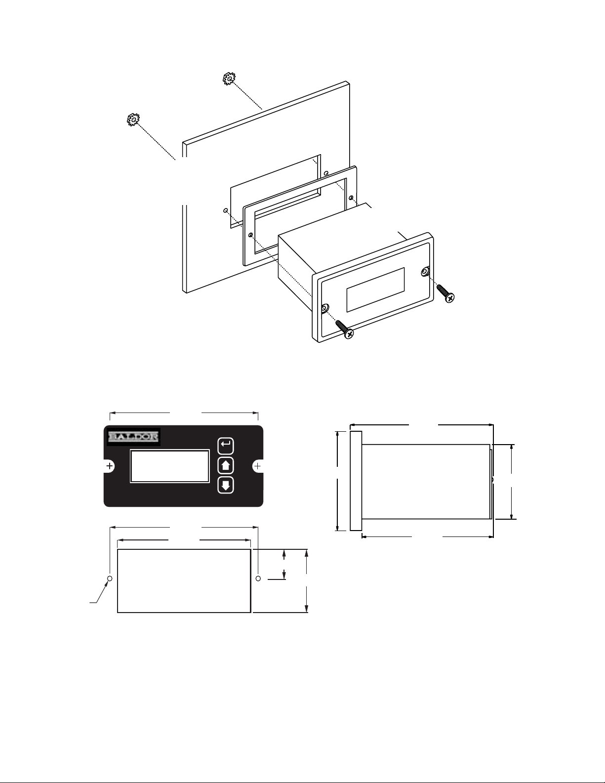
Mechanical Installation
Exploded Panel View
CUSTOMER
MOUNTING PANEL
(HOLE CUT-OUT FOR CONTROL
HOUSING APPROXIMATELY
3.622" WIDE BY 1.770" HIGH)
PANEL MOUNTING GASKET
(WITH THE ADHESIVE SIDE OF
GASKET FACING THE CUSTOMER
MOUNTING PANEL)
DTM8000 SERIES
TACHOMETER
.140" x 2
1) GASKET
2) (2) 6-32 X 3/4 PANHEAD BLACK OXIDE STAINLESS SCREWS
3) (2) #6 NUT WITH LOCKWASHER
Cut-out and Mounting Dimensions
4.000"
Tac h
ValuPage
Ite
SUPPLIED WITH EACH CONTROL:
m
TACHOMETER
4.000"
3.622
DTM8000-6
HOUSING DEPTH
4.625"
PANEL CUT-OUT
ENTER
"
0.885"
1.770"
2.289"
5.000"
1.656"
4.625"
4
Page 7
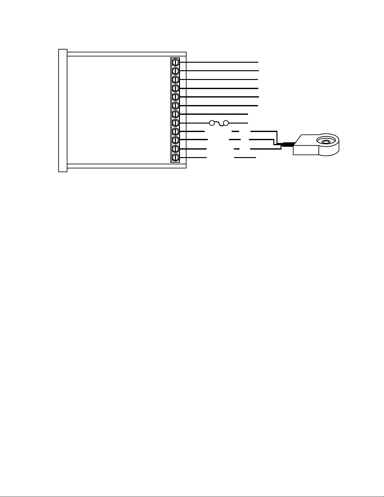
Electrical Installation & Diagrams
P1 Terminal Block Wiring Diagram
NC2
P1-1
P1-2
P1-3
P1-4
DTM8000-6
HOOK-UP
P1-5
P1-6
P1-7
P1-8
P1-9
P1-10
P1-11
P1-12
* Used for various functions, including quadrature counter mode.
P1 Terminal Block Descriptions
Alarm Output 2 - Normally Closed
C2
Alarm Output 2 - Common
NO2
Alarm Output 2 - Normally Open
NC1
Alarm Output 1 - Normally Closed
C1
Alarm Output 1 - Common
NO1
Alarm Output 1 - Normally Open
N
L
COM
+5V
S1
S2
AC NEUTRAL
COMMON
+5VDC
SIGNAL 1
SIGNAL 2
2 Amp
AC LINE
black
red
white
Form C Relay Output (Programmable)
}
Form C
Relay Output
}
(Programmable)
AC LINE INPUT
AC LINE INPUT
85-265VAC
}
*
PICK-UP
MOUNTED
P1-1 (2NC) This is the normally-closed contact of the second user assignable relay output.
P1-2 (2C) This is the common contact of the second user assignable relay.
P1-3 (2NO) This is the normally-open contact of the second user assignable relay output.
P1-4 (1NC) This is the normally-closed contact of the first user assignable relay output.
P1-5 (1C) This is the common contact of the first user assignable relay.
P1-6 (1NO) This is the normally-open contact of the first user assignable relay output.
P1-7 (AC / N) For single phase AC lines connect the Neutral side of your AC line to this terminal. For
systems with two hot AC lines, connect either of the Hot AC lines to this terminal.
P1-8 (AC / L) For single phase AC lines connect the Hot side of your AC line to this terminal. For
systems with two hot AC lines, connect either of the Hot AC lines to this terminal.
P1-9 (COM) This is the common point for the control logic. The speed sensor common lead as well
as any other source needing to reference the control common will be connected to this terminal.
P1-10 (+5V) This is a self-contained +5VDC power supply capable of up to 50mA. The speed sensor
supply lead can be connected to this terminal for its power source.
P1-11 (S1) This is the Signal input terminal for single channel operation or channel 1 of dual channel
operation. The signal lead of your speed or counter sensor will be connected here.
P1-12 (S2) This is the Signal input terminal for channel 2 during dual channel operation. The second
signal lead of the speed or position sensor should be connected here. This terminal is also used
as a reset input or function change input for various operations of the control. In counter modes,
this input may also be used as a counter reset or enable gate.
5
Page 8
Basic Operating Instructions
Rate, Time, and Counter Modes Explained
In Rate Mode, the DTM8000 measures the input frequency, converts it to the user-defined units, and
displays the rate in the display window of the user interface. Most applications utilize rate mode and
display in units such as gallons-per-minute, feet-per-second, and RPM.
In Time Mode, the DMT8000 measures the input frequency, converts it to the user-defined time units,
and displays the time in the display window. This mode is most-commonly used in time-sensitive
processes such as conveyor ovens and plating applications.
In Counter Modes, the DTM8000 counts each incoming pulse, scales it per the user-defined ratios, and
displays the count in the display window. Typical counting applications include linear material
measurement, cycle counters, and liquid volume measurement.
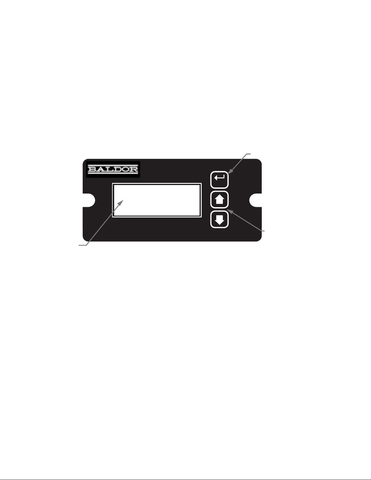
Visual Reference
ENTER (Select) Button
Tach
ENTER
Up & Down Buttons
Display Window
Ite
m
ValuPage
TACHOMETER
How to Change a Parameter's Value (The Short Story)
1. Hold down the Enter button until Parameter-Selection Mode is entered
2. Using the Up and Down buttons, select the desired parameter number to view or edit
3. Press the Enter button to change the value of the parameter
4. Using the Up and Down buttons, change the parameter's value as desired
5. Press the Enter button to permanently save the changes (Return to Parameter-Selection Mode)
6. Select parameter zero and press the Enter button to return to Running Mode
Operating the User Interface (The Long Story)
The LED display has three basic operating modes: Running Mode, Parameter-Selection Mode, and
Value Mode. Each of the three modes have specific visual indicators that allow the user to immediately
determine the current state or mode of the user interface. Parameter-Selection Mode and Value
Mode can only be entered if the Program Enable jumper is in the On position.
6
Page 9

Running Mode is the default display of the unit when power is applied. In Running Mode, the display
shows the measured value in the appropriate user-defined format of rate, time, or count. As the input
signal changes, the display is continuously updated to show the latest measurement. In this display
mode, the Up and Down buttons serve no function other that to reset or silence alarms if configured
accordingly. Example displays for rate, time, and count operating modes are 13.60, 45:30, and 9301.
Parameter-Selection Mode can be entered by simply pressing and holding the Enter button down for
three seconds. Once in Parameter-Selection Mode, the far left of the display will be a P. The right side
of the display will indicate the currently selected parameter number for editing purposes. Pressing the
Up or Down button will increase or decrease the selected parameter number on the display. Although
the parameter numbers are in numerical order, some numbers are skipped. These numbers represent
reserved parameters that are not displayed. Once the desired parameter number is displayed, a press
of the Enter button will change the display to the Value Mode. When in Parameter-Selection Mode,
pressing the Enter button with parameter 0 selected will cause the unit to return to Running
Mode. Example displays for Parameter-Selection Mode are P 1, P 11, and P 54.
Value Mode is used to modify the value of the selected parameter. When in Value Mode, the two dots
which form the colon, between digits two and three, will alternately flash (one, then the other) to inform
the user that a parameters value is being edited. Pressing the Up or Down button increases or
decreases the selected parameters value. Value changes take effect immediately. For example, when
scrolling through the alarm output conditions, the relay will activate as the always-active selection is
passed. Once the desired value is showing in the display window, pressing the Enter button again will
return to Parameter-Selection Mode. The new value is not saved in permanent memory until the Enter
button is pressed. Removing power from the unit while in Value Mode may result in the specified new
value being lost.
Detailed Configuration Instructions
Factory Set Configuration
When shipped from the factory, the following basic settings are in place:
Rate Mode Operation in RPM
S1 Signal Input Pulses-per-Revolution: 10
Decimal Point Display: Off
Auto-Ranging: Disabled
Alarm Output(s): Disabled
Resetting the Unit to Factory Settings
The factory settings can be easily restored using either of two methods. Both methods require the
Program Enable jumper to be in the On position. The first is to apply power to the unit with both the
Enter and Down buttons pressed for 3 seconds. The second is to change the value of parameter 95
to 5.
JP1 (Program Enable Jumper)
The JP1 jumper is located under the dust cover on the back end of the upper board. When the jumper
is set to the "Off" position, all programming features are locked out to the front panel user. When the
jumper is in the "On" position, the programming parameters are open to change. JP1 is shipped from
the factory set in the "On" position.
7
Page 10

Software Parameters
Parameter
0 Selecting this item exits to Running Mode n/a n/a
1 Model Number n/a 80
2 Software Build 1 – 9999 n/a
3 Hardware Version 1 – 9999 n/a
4 Serial Number – Major (reserved) n/a n/a
5 Serial Number – Minor (reserved) n/a n/a
10 Operating Mode 1 – Rate Mode
11 Display Intensity 0 – 31 (Dim – Bright) 20
14 Input Trigger / Prescaler Setup 1 - Every Rising Edge
16 Counter Mode Reset Configuration 1 – Reset Disabled
20 Display Reference 1 – 9999 (Display Units) 1000
21 Reference RPM 1 – 9999 (RPM) 1000
22 Pulses Per Revolution 1 – 9999 (PPR) 10
23 Recovery Rate 0 – 1000 (1/2 seconds)
24 Display Smoothing / Averaging 0 – 60 (seconds)
25 Decimal Poi nt Po sition 0 – DP Disabled (XXXX)
26 Auto-Ranging Configuration 0 – Auto-Ranging Off
27 Counter Mode Reset / Preload Value 0 – 9999 (counts) 0
30 Reserved
31 Reserved
32 Reserved
33 Reserved
34 Reserved
35 Reserved
36 Reserved
37 Counter Gate Configuration 1 – Disabled
Read-Only Parameters
General Setup
Signal Input #1 (S1) Setup
Description
Value Range
(units)
2 – Time Mode
3 – Up Counter
4 – Down Counter
5 – Up / Down Counter
2 – Every Falling Edge
3 – Falling Edge / 4
4 – Falling Edge / 16
2 – Reset on Keypress
3 – Reset on S2 Low
4 – Reset on S2 High
0 – Disabled
> 0 – Recovery 1/2 seconds
0 – Disabled
> 0 – Averaging Seconds
1 – X.XXX
2 – XX.XX
3 – XXX.X
4 – XXXX.
1 – Auto-Range on Overflow
2 – Auto-Ranging On
2 – Counting Enabled (Low)
3 – Counting Enabled (High)
Factory
Settings
1
1
1
10
1
0
0
1
User
Settings
8
Page 11

Software Parameters, cont'd
Parameter
40 Activation Conditions 0 – Always Off
41 Output Style & Reset Mode 1 – Constant & Auto Reset
42 Reset Configuration 1 – No Sil., Reset on Key
43 Display Flash On Active Alarm 0 – Alarm Flash Disabled
44 Pulse on Time 1 – 3600 (seconds) 1
45 Pulse off Time 1 – 3600 (seconds) 1
46 Pulse Count 0 – 9999 (pulses) 0
47 Lower Limit 0 – 9999 (display units) 0
48 Upper Limit 0 – 9999 (display units) 9999
50 Activation Conditions 0 – Always Off
51 Output Style 1 – Constant & Auto Reset
52 Reset Configuration 1 – No Sil., Reset on Key
53 Display Flash On Active Alarm 0 – Alarm Flash Disabled
54 Pulse On Time 1 – 3600 (seconds) 1
55 Pulse Off Time 1 – 3600 (seconds) 1
56 Pulse Count 0 – 9999 (pulses) 0
57 Lower Limit 0 – 9999 (display units) 0
58 Upper Limit 0 – 9999 (display units) 9999
95 Restore to Factory Settings 0 – Do Nothing & Exit
98 Save to User Setting Area 0 – Do Nothing & Exit
99 Restore from User Setting Area 0 – Do Nothing & Exit
Alarm Output #1 Configuration
Alarm Output #2 Configuration
Parameter Memory Commands
Description
Value Range
(units)
1 – Always On
2 – Active when Above
3 – Active when Below
4 – Active inside Range
5 – Active outside Range
2 – Constant & Manual Reset
3 – Pulsed & Auto Reset
4 – Pulsed & Manual Reset
2 – No Sil., Reset on S2 High
3 – No Sil., Reset on S2 Low
4 – Sil., Reset on Key
5 – Sil., Reset on S2 High
6 – Sil., Reset on S2 Low
1 – Alarm Flash Enabled
5 – Restore Factory Settings
5 – Save Setting
1 – Restore Settings
Factory
Settings
0
1
1
0
0
1
1
0
0
0
0
User
Settings
9
Page 12

Parameter Descriptions
Parameter 0 Exit to Running Mode
When parameter 0 is selected in Parameter-Selection Mode, the unit will return to Running Mode
and display the running value. This should be selected once changes to parameters are
completed.
Parameter 1 Model Number (Read Only)
This is a number which represents the base model number for the product. For the DTM8000,
the model code is 80.
Parameter 2 Software Build (Read Only)
The software build is a code which identifies the software version of the unit.
Parameter 3 Hardware Version (Read Only)
The hardware version is a code which identifies which hardware was used to build the unit.
Parameter 4 & 5 Serial Number, Major & Minor (Read Only)
These parameters are reserved for future use as an electronic serial number and are unique to
each manufactured unit.
Parameter 10 Operating Mode
This parameter defines the basic mode of operation for the entire unit. It determines if the unit
is measuring rate, time, or count information. The following modes are available:
Mode 1 Rate Mode
Rate mode displays measurements in rate units such as RPM, Gallons per Hour, or Feet
per Second.
Mode 2 Time Mode
Time mode displays measurements in time units using the format AA:BB. By default
AA:BB represents minutes (AA) and seconds (BB). Optionally, it can be configured to
represent hours (AA) and minutes (BB) or other user-defined units with a 1:60 relationship.
Mode 3 Up Counter
Counter modes (3 5), display measurements in pulse counts or user-defined units which
are proportional to pulse count. In these modes, the DTM8000 will count the pulses which
are applied to the S1 input and display the related value. In this mode, each input pulse
increments the counter.
Mode 4 Down Counter
Same as Mode 3 above except each input pulse decrements the counter.
Mode 5 Up / Down Counter
Same as Mode 3 above except each input pulse either increments or decrements the
counter depending upon the state of Signal Input #2 (S2). If S2 is tied to common, the
counter is incremented; otherwise, it is decremented.
Parameter 11 Display Intensity
This parameter adjusts the intensity of the LED display digits in the front panel of the unit. The
values of 0 31 correspond to a gradual change from very dim to very bright. This is often useful
when used in the same panel as other pieces of equipment with LED displays and a uniform
display brightness is desired.
Parameter 14 Input Triggers / Prescale
This parameter determines how the S1 signal input is processed. It specifies which signal edge
is used for the measurements and the value of the internal frequency divider or prescaler.
Modes 3 and 4 should only be used if the input pulse rate exceeds the unit's maximum native
pulse rate (see specifications for details); otherwise, timing and counting calculations may
become sluggish and unnecessarily inaccurate.
Mode 1: Every Rising Edge, No Prescaler
In this mode, the signal input is measured at every rising edge.
Mode 2: Every Falling Edge, No Prescaler
In this mode, the signal input is measured at every falling edge.
10
Page 13

Mode 3: Falling Edge, Prescaler = 4
In this mode, the signal input is measured at every 4th falling edge. This mode is especially
useful when the signal input frequency is beyond the native pulse-per-minute range of the
DTM8000. Because unit will automatically compensates for the prescaler, there is no
need to factor in the prescaler value when setting the Display and RPM Reference
parameters.
Mode 4: Falling Edge, Prescaler = 16
Same as Mode 3 except the signal input is only measures every 16th falling edge.
Parameter 16 Counter Reset Configuration
In counter applications, it is often desirable to have the user or an external signal reset the
counter value to zero or some predetermined value. This parameter specifies which actions
will cause the counter to reset to the Counter Reset / Preset Value, parameter 27.
Mode 1: Reset Disabled
The counter cannot be reset.
Mode 2: Reset On Button Press
The counter will reset to the Counter Reset / Preset Value, parameter 27, when any of the
user-interface buttons are depressed.
Mode 3: Reset On S2 Input Low (Wired To Common)
The counter will reset to the Counter Reset / Preset Value, parameter 27, when S2 (signal
2) is brought to an electrically low state or wired to the unit's common.
Mode 4: Reset On S2 Input High (Not Wired To Common)
The counter will reset to the Counter Reset / Preset Value, parameter 27, when S2 (signal
2) is brought to an electrically high state (+5V) or left to float disconnected from the unit's
common.
Parameter 20 Signal Input 1 (S1) Display Reference
This is the number to be displayed when at the user-specified motor Reference RPM. In Rate
Mode, this value represents the numerator of the rate unit such as feet, ounces, or revolutions.
In Time Mode, this value represents the reference time measured in seconds or minutes. If the
desired display is HH:MM, then all values should be entered in minutes. If MM:SS is desired, then
all values should be entered in seconds. In Counter Modes, this value is the reference count
ratio which corresponds to the number of counts which equate to the specified number of
reference pulses, parameter 21. See applications for examples.
Parameter 21 Signal Input 1 (S1) Reference RPM (Reference Pulses in Counter Modes)
This is the reference RPM at which the Display Reference value should be displayed. In Rate
and Time Modes, this value represents the RPM of the encoder to which the Display Reference
corresponds. In Counter Modes, this value is the Reference Pulses which correspond the the
specified number of displayed counter, parameter 21. See applications for examples.
Parameter 22 Signal Input 1 (S1) Pulses per Revolution
This is the number of pulses per revolution. Value may be from 1 to 9999.
Parameter 23 Signal Input 1 (S1) Recovery Rate
This is the rate at which the display will attempt to recover once the pulse train appears to have
stopped. The recovery rate is the number of half seconds which the unit will wait before dividing
(Rate Mode) or multiplying (Time Mode) the display value by 2 in an attempt to accurately
represent the current speed or time. In the absence of input pulses, this will continue at regular
intervals until either 0 (Rate Mode) or 99:99 (Time Mode) is reached. Setting this parameter to
0 will disable the automatic recovery feature. If this parameter is set too low for the application,
the division or multiplication may prematurely occur causing the reading to read too high, too low,
or unstable. This can easily be corrected by simply increasing this parameter's value or
disabling it by setting it to zero.
Parameter 24 Signal Input 1 (S1) Display Smoothing / Averaging
This is the amount of time, in 1-second increments, which will be averaged before updating the
display. Setting this parameter to 0 will disable the averaging feature.
11
Page 14

Parameter 25 Signal Input 1 (S1) Decimal Point (DP) Position
This selects the format of the display with respect to the decimal points position. This parameter
does not effect the value entry for other parameters. For example, it the user desires to display
10.00 at an input of 300RPM, then parameter 20 would be set to 1000, parameter 21 would be
set to 300, and parameter 25 would be set to 2.
Mode 0: Fixed XXXX
Mode 1: Fixed X.XXX
Mode 2: Fixed XX.XX
Mode 3: Fixed XXX.X
Mode 4: Fixed XXXX.
Parameter 26 Signal Input 1 (S1) Auto-Ranging Configuration
This selects how the unit auto-ranges and formats the numbers for the display.
Mode 0: Auto-Ranging Disabled
The auto-ranging mode is disabled. Ignoring decimal points, this limits the units display
range from 0 to 9999. Values beyond this range will display as an overflow error (-OF-).
Mode 1: Auto-Ranging On Overflow Only
In this mode, auto-ranging will only be activated if the display value exceeds the maximum
native display value. For example, in XX.XX decimal point mode, 99.99 would be the
maximum native value for a 4-digit display. When the display is in overflow, it will display
only the 4 most significant digits and the decimal point will flash.
Mode 2: Auto-Ranging Always Active
In this mode, auto-ranging is always active and continuously attempts to display the 4 most
significant digits. For example, the display will automatically range from 0.001 to 9999 as
needed. In this mode, any value over 9999 will be displayed as an overflow error (-OF-).
Parameter 27 Counter Reset / Preset Value
This is the value that will automatically be loaded into the display after the counter has been reset.
See Counter Reset Configuration, parameter 16, for more details.
Parameter 30, 31, 32, 33, 34, 35, and 36
Reserved For Future Use.
Parameter 37 Signal Input 2 (S2) Counter Gate (Enable / Disable) Configuration
This selects how the S2 input is utilized in single channel counter modes.
Mode 1: Disabled (Required For Up / Down Counter Mode)
The S2 input will not function as a gate control and instead will act as the second input for
dual-channel counter operation.
Mode 2: Counting Enabled When S2 Input Low (Wired To Common)
The unit will continue to count input pulses as long as the S2 is in an electrically low state
or connected to the unit's common terminal. When the S2 input goes high (+5V) or is
allowed to float disconnected, the counter will be frozen at its current value.
Mode 3: Counting Enabled When S2 Input High (Not Wired To Common)
The unit will continue to count input pulses as long as the S2 is in an electrically high (+5V)
state or allowed to float disconnected. When the S2 input goes low or is wired to the unit's
common, the counter will be frozen at its current value.
Parameter 40 & 50 Alarm 1 & 2 Conditions
This defines which conditions will result in the alarm 1 or alarm 2 outputs being activated.
Mode 0: Always Inactive
The alarm output will remain in an inactive state. In this state, the NC and C contacts will
be internally electrically connected.
Mode 1: Always Active (When Power Is Applied)
The alarm output will become active when the power is applied to the unit. In this state,
the NO and C contacts will be internally electrically connected.
Mode 2: Active When Display Value Above Limit
The alarm output will activate when the displayed value is above the upper limit settings,
parameters 48 and 58 accordingly.
12
Page 15

Mode 3: Active When Display Value Below Limit
The alarm output will activate when the displayed value is below the lower limit settings,
parameters 47 and 57 accordingly.
Mode 4: Active When Display Value Inside Range
The alarm output will activate when the displayed value is greater than or equal to lower
limit settings and less than or equal to the upper limit setting.
Mode 5: Active When Display Value Outside Range
The alarm output will activate when the displayed value is less than the lower limit setting
or greater than upper limit setting.
Parameter 41 & 51 Alarm 1 & 2 Output Style & Reset Configuration
This setting configures the output mode and reset method for the alarm outputs.
Mode 1: Constant & Auto Reset
In this mode, the alarm output will remain active until the alarm condition ceases to exist.
The alarm will automatically reset when the conditions return to normal.
Mode 2: Constant & Manual Reset
In this mode, the alarm output will remain active until the alarm is reset manually. See
parameters 42 and 52 for details.
Mode 3: Pulse & Auto Reset
In this mode, the alarm output will pulse on and off until the alarm condition ceases to exist.
The pulsed modes are commonly used for audible alarms where a constant output would
be considered distracting or awkward. The alarm will automatically reset when the
conditions return to normal.
Mode 4: Pulse & Manual Reset
In this mode, the alarm output will pulse on and off until the alarm is reset manually. See
parameters 42 and 52 for reset details. The pulsed modes are commonly used for audible
alarms where a constant output would be considered distracting or awkward.
Parameter 42 & 52 Alarm 1 & 2 Reset Configuration
This setting determines which actions will cause an active alarm to be silenced or reset.
Mode 1: No Silencing, Reset On Any Button Press
In this mode, an active alarm cannot be silenced. Once the alarm condition ceases to
exist, however, any user-interface button may be pressed to cause a manual reset.
Mode 2: No Silencing, Reset On S2 Input High (Not Wired To Common)
Similar to Mode 1. Once the alarm condition ceases to exist, setting the S2 input to a high
(+5V) state or allowing it to float disconnected will cause a manual reset.
Mode 3: No Silencing, Reset On S2 Input Low (Wired To Common)
Similar to Mode 1. Once the alarm condition ceases to exist, setting the S2 input to a low
(COM) state or wiring it to common will cause a manual reset.
Mode 4: Silencing Enabled, Reset On Any Button Press
When the conditions for an active alarm persist, pressing any user-interface button will
result in the alarm being silenced or deactivated, but not reset. A second attempt to reset
the alarm must be made after the condition cease to exist to clear the alarm.
Mode 5: Silencing Enabled, Reset On S2 Input High (Not Wired To Common)
Similar to Mode 4. Setting the S2 input to a high (+5V) state or allowing it to float
disconnected will cause the alarm to be silenced or reset depending on the current state
of the alarm conditions.
Mode 6: Silencing Enabled, Reset On S2 Input Low (Wired To Common)
Similar to Mode 4. Setting the S2 input to a low (COM) state or wiring it to common will
cause the alarm to be silenced or reset depending on the current state of the alarm
conditions.
Parameter 43 & 53 Alarm 1 & 2 Display Flash On Alarm
This will cause the display to flash when an alarm conduction is active.
Parameter 44 & 54 Alarm 1 & 2 Pulse on Time
This parameter defines the number of seconds the output should be enabled during the on
phase of an active pulsing alarms output. See application samples for examples.
13
Page 16

Parameter 45 & 55 Alarm 1 & 2 Pulse off Time
This parameter defines the number of seconds the output should be disabled during the off
phase of an active pulsing alarms output.
Parameter 46 & 56 Alarm 1 & 2 Pulse Count
This setting determines how many pulses are output when the alarm is activated and is
configured in pulse output style. When 0 is entered, the unit will be set for continuous pulses while
the alarm is active.
Parameter 47 & 57 Alarm 1 & 2 Lower Limit
This setting defines either the lower limit or lower end of a range for the alarm region. Alarm limits
are set in display units without regard to decimal point or colon position. In Rate and Counter
Modes, a limit of 123 could represent a display value of 123, 12.3, 1.23, or 0.123. When in Time
Mode, a limit of 123 would represent 1:23 on the display.
Parameter 48 & 58 Alarm 1 & 2 Upper Limit
This setting defines either the upper limit or upper end of a range for the alarm region. Alarm
limits are set in display units without regard to decimal point or colon position. In Rate and
Counter Modes, a limit of 123 could represent a display value of 123, 12.3, 1.23, or 0.123. When
in Time Mode, a limit of 123 would represent 1:23 on the display.
Parameter 95 Factory Settings Command
When set to a value of 5, the unit will be reset to factory settings. This can also be achieved by
applying power to the unit with both the Enter and Down buttons depressed. The programming
jumper must be in the "On" position for this method to function.
Parameter 98 Save to User Settings Area Command
When set to a value of 5, the unit will store all adjustable parameters to the user settings area.
The user settings area is intended to be a location where a user can store settings specific to
their application. A user can easily refresh their custom settings. Another common use for this
area is testing and initial setup. The user can store known-good settings here and easily
experiment without the fear of losing the optimal configuration.
Parameter 99 Restore from User Settings Area Command
When set to a value of 1, the unit will restore the all adjustable parameters from the user settings
area. See parameter 98 for additional information.
14
Page 17

Pump Flow Monitor with Audible and Visual Alarm
Description:
A pump monitor which displays the pump rate in gallons per minute with an audible and visual
alarm output which will warn the operator of excessively low flow conditions under 5.00 GPM.
The alarm should not be able to be silenced and should be reset when any front-panel button is
pressed. The display should indicate in the format xx.xx (GPM). Due to normal fluctuations in
flow rates, it is desirable to have the display filter or average the value over 3 seconds to produce
a more accurate and steady display.
Application Diagram:
Application Examples
Motor Control
Fluid
Outlet
ItemValuPage
36.24
TACHOMETER
DTM8000 Meter
Wiring Diagram:
DTM8000-6
Parameter Configuration:
Encoder
Tach
ENTER
Pump Specs:
53 Shaft Rotations = 3 Gallons
Audible
Annunciator
NC2
P1-1
P1-2
P1-3
P1-4
P1-5
P1-6
P1-7
P1-8
P1-9
P1-10
P1-11
P1-12
C2
NO2
NC1
C1
NO1
N
L
COM
+5V
S1
S2
Not Used
Not Used
Not Used
Not Used
Not Used
2 Amp
white
}
black
red
Fluid
Pump
Inlet
120VAC
Audible
Annunciator
AC Line Input 85-265VAC, 50-60 Hz
Encoder
Parameter Value Notes
10 1 Rate Mode Setting (GPM is a rate-based unit)
20 3 00 Display should indicate 3.00 GPM (300) when motor at Reference RPM, parameter 21
21 53 This is the RPM at which the Display Reference, parameter 20, should be displayed
22 10 Pulses per revolution of shaft encoder or pickup is 10 PPR
24 3 Display filtering / averaging set to 3 seconds
25 2 Decima l point p osition set to XX.XX on dis play
40 3 Alarm active when display value is below lower limit
41 2 Constant alarm output with manual reset required
42 1 No silencing, reset on any button press
43 1 Flash display when alarm is active
47 500 Lower limit setting for 5.00 GPM (500). Limits are entered without regard for decimal
point position
15
Page 18

Conveyor Oven Time Monitor with Over-Heating Alarm
Description:
An oven monitor displaying the tunnel time in minutes and seconds. The tunnel time is defined
as the time it takes for the heated object on the conveyor to travel from point A to point B in the
application diagram below. A visual indicator should activate if the tunnel time rises above a
preset limit of 22 minutes and 30 seconds which could cause overheating of the processed
material. The indicator should automatically reset when the tunnel time returns to the normal
operating range. For ease of use, the display should be averaged over a period of 1 second.
Application Diagram:
Motor Control
Wiring Diagram:
AB
Heat Source
Tunnel Oven
Tach
Ite
ValuPage
m
ENTER
18:40
TACHOMETER
DTM8000 Meter
DTM8000-6
Connect to
Coupling
P1-1
P1-2
P1-3
P1-4
P1-5
P1-6
P1-7
P1-8
P1-9
P1-10
P1-11
P1-12
Encoder
NC2
C2
NO2
NC1
C1
NO1
N
L
COM
+5V
S1
S2
Gear Motor
Drive Train Specs:
1250 RPM at non-reduced
motor shaft equates to
9 minutes and 15 seconds
of tunnel time
Not Used
Not Used
Not Used
Not Used
Not Used
Not Used
2 Amp
AC Line Input 85-265VAC, 50-60 Hz
}
black
red
white
Coupling to
Chain Drive
Encoder
Parameter Configuration:
Parameter Value Notes
10 2 Time Mode Setting
20 555 Display should indicate 9:15 (555) when motor at Reference RPM, parameter 21. In
time mode, all display values are entered in total number of seconds.
For example, 555 = (9 minutes * 60 seconds-per-minute) + 15 seconds.
21 1250 This is the RPM at which the Display Reference, parameter 20, should be displayed.
22 10 Pulses per revolution of shaft encoder or pickup is 10 PPM
24 1 Display filtering / averaging set to 1 seconds
40 4 Alarm active when display value is above upper limit
41 1 Constant alarm output with automatic reset
43 1 Flash display when alarm output is active
48 1350 Upper limit setting for 22 minutes and 30 seconds. In time mode, all limits are entered in
total number of seconds.
For example, 1350 = (22 minutes * 60 seconds-per-minute) + 30 seconds.
16
Page 19

Take-up / Pay-out Reel Material Measurement with Alarm
Description:
A take-up / pay-out system where the DTM8000 displays a measurement of dispensed or
accumulated material in linear yards. Once the desired amount of material, 1500 yards,
has been dispensed or accumulated, an external light should illuminate to indicate that the
specified material volume has passed. At this point, the user must be able to press a button
on the user interface to reset the count to zero and the process repeats.
Application Diagram:
Tension
Motor #1
Belt
Capstan
Motor
Belt
Speed Control
Pinch Rollers
Capstan Drive Specs:
28.3 Revolutions of the
Capstan motor equate to
50 linear yards of material
Belt
Tension
Motor #2
Wiring Diagram:
Torque
Control #1
DTM8000-6
Tension
Tach
ItemValuPage
3650
TACHOMETER
DTM8000 Meter
P1-1
P1-2
P1-3
P1-4
P1-5
P1-6
P1-7
P1-8
P1-9
P1-10
P1-11
P1-12
Encoder
ENTER
NC2
C2
NO2
NC1
C1
NO1
N
L
COM
+5V
S1
S2
Not Used
Not Used
Not Used
Not Used
Not Used
2 Amp
Tension
black
red
white
Pylon-Style
Illuminated
Alarm
Torque
Control #2
120VAC
Illuminated
Pylon-Style
Alarm
AC Line Input 85-265VAC, 50-60 Hz
}
Encoder
Attached to Driven
Capstan Pinch Rollers.
Parameter Configuration:
Parameter Value Notes
10 3 Up-Counter Mode Setting
16 2 Conf igure counte r to reset on any button press
20 500 Display should increment 50 linear yards for each Reference Count, parameter 21.
Because the initial val ues were 28.3 revoluti on s per 50 linear yards, each is multipli ed by
10 to gi ve an even number to in cr ease accuracy sinc e the display can be programmed in
whole numbers .
21 283 In count mode, the Reference RPM is set in revolutions. 283 has been entered here to
represen t 2 8. 3 r evoluti ons and the D i splay Refe rence h as also been multi p l ied by 10 t o
yield whole numbers.
22 10 Pulses per revolution of shaft encoder or pickup is 10 PPM
40 4 Alarm active when display value is above upper limit
41 2 Constant alarm output with manual reset required
42 1 No silencing, reset on any button press
48 1500 Upper limit setting for 1500 linear yards
17
Page 20

Bi-directional Incremental Position Display
Description:
A system is needed which will track the position of a bi-directional linear-motion platform
and allow the user to select a home or zero position. The display should read in inches
and indicate the position of the platform at all times.
Application Diagram:
Platform
Drive Train Specs:
Wiring Diagram:
40 Revolutions = 3.5 In.
of Platform Motion
Tach
ItemValuPage
ENTER
263.4
TACHOMETER
DTM8000 Meter
DTM8000-6
P1-1
P1-2
P1-3
P1-4
P1-5
P1-6
P1-7
P1-8
P1-9
P1-10
P1-11
P1-12
Encoder
NC2
C2
NO2
NC1
C1
NO1
N
L
COM
+5V
S1
S2
Linear-Motion System
Motor Control
Not Used
Not Used
Not Used
Not Used
Not Used
Not Used
2 Amp
AC Line Input 85-265VAC, 50-60 Hz
}
black
red
white
brown
Connect to
Coupling
Coupling to
Chain Drive
Gear Motor
Encoder
Parameter Configuration:
Parameter Value Notes
10 5 Up/Down Counter Mode
20 35 Beca u se th e initial values were 40 revolutions per 3.5 inches of platform motion, each is
multipli e d by 10 to give an even number to incre ase accuracy since t he disp lay can be
program m ed in whole numbers. Additionally, because of the decimal point position, the
Display Reference is multiplied by 10 to generate the proper display format. Without the
second multiplication by 10, the display would only read 3.5 inches when the drive motor
turned 400 revolutions.
21 400 In count mode, the Reference RPM is set in revolutions. 400 has been entered here to
represent 40 revolutions and the Display Reference has also been multiplied by 10 to yield
whole numbers .
22 10 Pul s es per revolution of shaft encoder or pickup is 10 PPM
25 3 Decimal point position set to XXX.X on display
18
Page 21

Troubleshooting
Problem Possible Case Solution
Display is blank Power not applied
Defective unit
Display is di m Display intensity
When power is
applied, “LF-L” is
displayed
When power is
applied, “LF-H” is
displayed
The first or second
alarm output does
not seem to
function
parameter is too low
AC line supplying
power to unit has too
much noise
AC line supplying
power to unit has an
abnormally low
frequency
AC line supplying
power to unit has too
much noise
AC line supplying
power to unit has an
abnormally high
frequency
Second alarm output
parameters not
configured proper ly
Using a volt meter, verify that a voltage between 85 and 265VAC is measured between
the L and N terminal block positions.
Contact technical support for additional help and i nstructions.
Editing and increasing the display intensity parameter should cause the display digits to
become brighter.
Review routing of power wires in machine to minimize electrical noise. Look for other
devices which share the same circuit which may be producing unacceptable levels of line
noise. In some applications, such as welding equipment, a careful regiment of applying
an AC line filter, re-routine wires, divi di ng circuits, using shielded cable, and properly
grounding devices will usually solve the problem.
The unit is designed to operate wi th AC lines from 48-62 Hertz (cycles per second).
Second alarm output parameters not configured properly
Review alarm output #2 paramete rs. The fi rst and second alarm relay outputs can be
tested by selecting the “Always On” value for the Activation Condition parameters for the
respective alarm output. When doing this, the relay click should be audible and the NC
(Normally Closed) and C (Common) terminals should become internally shorted at the
terminal block.
19
Page 22

- Notes -
20
Page 23

- Notes -
21
Page 24

BALDOR ELECTRIC COMPANY
P.O. Box 2400
Ft. Smith, AR 72902–2400
(479) 646–4711
Fax (479) 648–5792
www.baldor.com
CH
TEL: +41 52 647 4700
FAX:+41 52 659 2394
I
TEL: +39 11 562 4440
FAX:+39 11 562 5660
Baldor Electric Company
MN1327
D
TEL: +49 89 90 50 80
FAX:+49 89 90 50 8491
AU
TEL: +61 29674 5455
FAX:+61 29674 2495
UK
TEL: +44 1454 850000
FAX:+44 1454 859001
CC
TEL: +65 744 2572
FAX:+65 747 1708
F
TEL: +33 145 10 7902
FAX:+33 145 09 0864
MX
TEL: +52 477 761 2030
FAX:+52 477 761 2010
Printed in USA
04/03
 Loading...