

Page 1
Instruction Manual for Connecting Sensors on Pillow Block Bearings
Temperature Monitor, Alarm System, Embedded Thermocouple and
Transmitter, Vibration Accelerometer, and Proximity Switch
Bearing Temperature Monitor-Alarm System
A. Connection to a PLC:
– Use an AC input card 120 VAC
– Cards available from Allen Bradley for SLC 500 are
1746-IA4, 1746-IA8 and 1746-IA16
B. If no PLC is used, the DODGE Light and Buzzer Alarm
Module can be used (DODGE Part No. 063524).
Connections are shown below.
DANGER: The user is responsible for conforming
with the National Electrical Code and all other
applicable local codes. Wiring practices, grounding,
disconnects and overcurrent protection are of
particular importance. Failure to observe these
precautions could result in severe bodily injury or
loss of life.
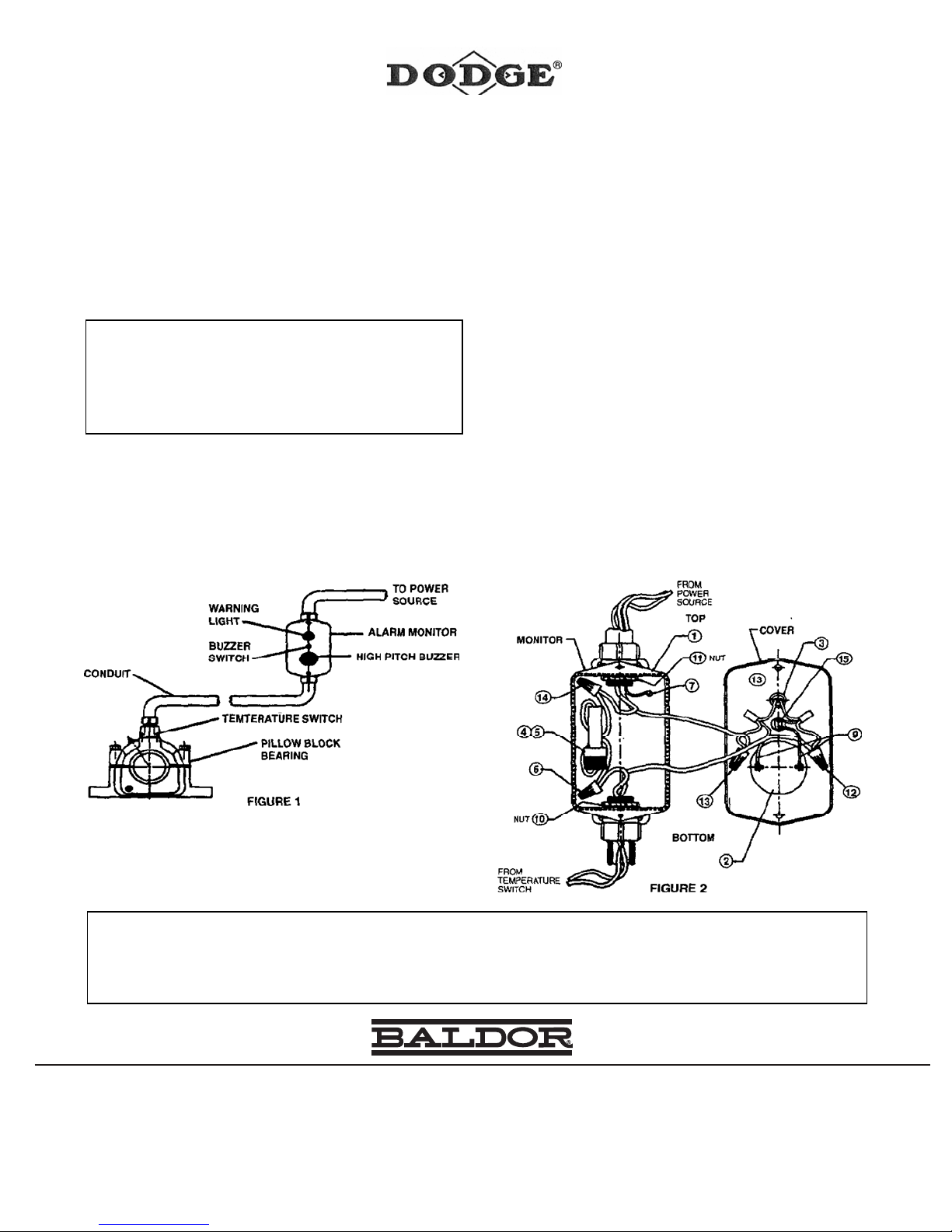
I. Bearing Temperature Alarm Monitor System:
1. A complete installation, Pillow Block with temperature
switch, conduit, and alarm is shown in Figure 1. Items
supplied by DODGE are the Pillow Block with
temperature switch and the alarm monitor. Conduit,
wires, and liquid tight fittings are supplied by the user.
2. A DODGE Pillow Block with temperature switch mounts
on the shaft exactly like a standard pillow block
.
screws on the front. (See Figure 2)
3. Install a conduit between the monitor and the bearing
1
using
/2" liquid tight fittings.
4. Use 16 AWG wires installed in the conduit to connect
the temperature switch to the alarm monitor.
5. Verify that AC power is disconnected and locked out or
tagged at the power source. Bring AC power wires to
the top of the alarm monitor and secure using
tight fitting.
6. At the bearing remove the temperature switch cover,
nect the two leads of the temperature switch to the
con
two wires installed in step 4 above using approved wire
nut connectors and reinstall the cover.
7. Connect the end of one wire that is connected to the
switch to one end of the fuse (6). Connect the second
wire from the temperature switch to the joint (12).
8. Connect the black (hot) wire from the power source to
the other end of the fuse (14). Connect the white
(neutral) wire to lead (13). Connect the green (ground)
wire to the ground screw (7) on the back of the monitor.
Make sure the screw is tight and the wire is secure.
9. Replace the cover and secu
the two screws
re with
1
/2" liquid
.
II. Alarm Monitor Installation:
1. Install the alarm monitor in a visible and close safe
place using the four mounting holes on the back of the
enclosure.
2. Remove the enclosure cover by removing the two
WARNING: Because of the possible danger to person(s) or property from accidents which may result from the improper use of products, it is important that
correct procedures be followed. Products must be used in accordance with the engineering information specified in the catalog. Proper installation,
maintenance and operation procedures must be observed. The instructions in the instruction manuals must be followed. Inspections should be made as
necessary to assure safe operation under prevailing conditions. Proper guards and other suitable safety devices or procedures as may be desirable or as may
be specified in safety codes should be provided, and are neither provided by Baldor Electric Company nor are the responsibility of Baldor Electric Company.
This unit and its associated equipment must be installed, adjusted and maintained by qualified personnel who are familiar with the construction and operation
of all equipment in the system and the potential hazards involved. When risk to persons or property may be involved, a holding device must be an integral part
of the driven equipment beyond the speed reducer output shaft.
P.O. Box 2400, Fort Smith, AR 72902-2400 U.S.A., Ph: (1) 479.646.4711, Fax (1) 479.648.5792, International Fax (1) 479.648.5895
6040 Ponders Court, Greenville, SC 29615-4617 U.S.A., Ph: (1) 864.297.4800, Fax: (1) 864.281.2433
© Baldor Electric Company
MN3043 (Replaces 499807) 06/30/09
*3043-0609*
World Headquarters
Dodge Product Support
www.baldor.com
All Rights Reserved. Printed in USA.
Page 2

Page 3
Pillow Block Assemblies with Embedded Thermocouple and Transmitter
A. Connection to a PLC:
– The transmitter output can be connected directly to an
analog input card with internal loop power supply.
– Typical cards that can be used from Allen Bradley are
1771-NBSC and 1771-NB4S.
B. If a PLC is not available, the panel mounted temperature
indicator available from DODGE can be used to power
the transmitter and display the temperature. The indicator
model is CT1010, Part No. 055221. The indicator has two
settable alarm relays for warning and shut down. The
connections are shown in the instruction manual supplied
with the indicator.
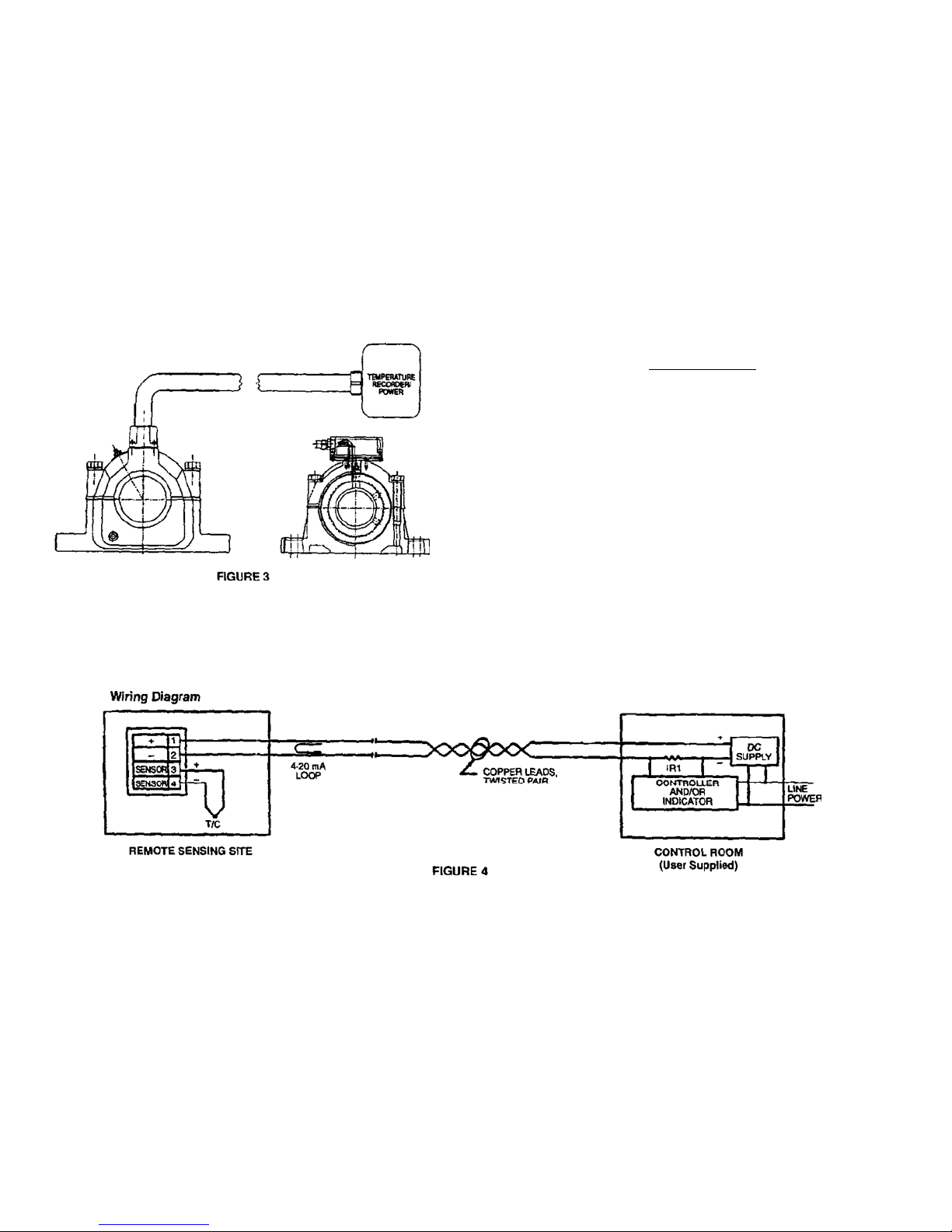
I. Pillow block assemblies equipped with embedded
thermocouple, transmitter and data acquisition system i
shown in Figure 3.
s
II. Connection of pillow block with loop driver or data
acquisition system is shown in Figure 4 and Figure 5.
1. Take the top cover (1) off from the housing (2) by
removing the four screws.
2. Install a
cover (1) using the hole on the side.
3. Use a flex conduit (4) between the cover and the loop
driver or your data acquisition system. Voltage supply
required is 8.5 volts to 35 volts DC with no load.
4. Install the signal wires (two twisted copper wires) (5)
inside the flex conduit.
5. Connect the ends of the two wires to the transmitter
(6) terminals 1 and 2 and secure the screws.
6. Lo
op resistance: The maximum allowable resistance
of the signal carrying load, including extension wires
and load resistance, is given by this formula:
R approximately = (V supply – 8.5V)
.02 amps
Example:
If supply voltage is 24 VDC, the loop resistance must
be less than 775 ohm (wires plus R1). Use 80% of the
calculated value to protect against drop in voltage.
7. Replace the cover and tighten the four (4) screws.
8. Connect the other ends of the two wires (5) to your
loop driver/power supply or your data acquisition
system with built-in power supply.
9. Your system should now be able to read the
temperature between 0 and 250ºF.
10. The output of the transmitter is 4–20 mA (milliamps).
1
/2" liquid tight electrical fitting (3) on the
2
Page 4

Pillow Block Assemblies with Accelerometer
A. Connection to a PLC:
– In order to connect the accelerometer to a PLC, a
vibration transmitter is needed to power the
accelerometer and to transmit the signal in a suitable
form.
– The vibration transmitter produces 4 to 20 mA
proportional to the vibration velocity and ±5 volts
signal proportional to acceleration. The transmitter
needs 20 to 30 DC voltage supply. The transmitter is
available from DODGE, Part No. 055222.
– The output of the transmitter can then be connected
to Allen Bradley 1746-NI4 card.
B. Connection to a Data Acquisition System:
– A data acquisition system is normally composed of a
PC with analog input cards plus the required software.
– In order to interface the accelerometer to the analog
input card, the above transmitter can be used. A lower
cost power conditioner module can also be used. The
power conditioner module will produce plus or min us
5 volts when powered by a 24 volts DC power supply.
The module is available from DODGE, Part No.
055223.
– The output of the transmitter or module should then
be connected to the input analog card in the PC. It is
important that the vibration be sampled at 10,000 Hz.
1. Remove the top cov er from the housing very carefully by
removing the four screws. Note that the accelerometer is
attached to the cover (1).
2. Install a
using the hole on the side.
3. Use a flex conduit (2) between the cover and the
accelerometer power supply or the data acquisition
system if the system has a built-in power supply.
4. Insert the accelerometer cable through the conduit and
secure the nuts to the accelerometer and the power
supply (3) and (4).
5. Use a DC power supply 18 to 28 volts with current
capability of 2 to 20 mA. Attached is the specifications for
the accelerometer and its power supply.
1
/2 inch liquid tight electrical fitting to the cover
DYNAMICS ENGLISH S.I.
Sensitivity (±10%)
Measurement Range ±50 g ±490 m/s2
Resolution 0.0002 g 0,0019 m/s2
Frequency Range: (±10%)
(±3 dB) 30–600,000 cpm (0.5–10,000 Hz)30–600 000 cpm (0,5–10 000 Hz)
Resonant Frequency
(A)
100 mV/g 10,2 mV/m/s2
(B)
(C)
1,080 kcpm (18 kHz) 1 080 kcpm (18 kHz)
ACCELEROMETER CHARACTERISTICS
66–300,000 cpm (1.1–5,000 Hz) 66–300 000 cpm (1,1–5 000 Hz)
3
Page 5

Transverse Sensitivity
Amplitude Linearity
ENVIRONMENTAL
Shock Limit (peak) 5,000 g 49 050 m/s2
Temperature Range -65º to + 185ºF -54º to +85ºC
Temperature Coefficient -0.05%/ºF -0,09%/ºC
Strain Sensitivity
ELECTRICAL
Setting Time
Excitation Voltage 18 to 28 volts 18 to 28 volts
Excitation Current 2 to 20 mA 2 to 20 mA
Output Impedance <100 ohms <100 ohms
Electrical Noise Broadband
Electrical Noise Spectrical: 10 Hz
100 Hz
1000 Hz
Output Bias 8 to 14 volts 8 to 14 volts
Full Scale Output Voltage ±5 volts ±5 volts
Discharge Time Constant
MECHANICAL ENGLISH S.I.
Size: Hex × Height 11/16 × 1.1 in 17.5 × 27.9 mm
Weight 1.2 oz 35 gm Single Point Calibration @ 100 Hz
Mounting Thread (female)
Mounting Torque 2 to 5 ft-lb 2,7 to 6,8 N-m (A) Conversion Factor: 1 g = 9,81 m/s2
Sensing Element Ceramic Ceramic (B) 1 Hz = 60 cpm (cycles per minute)
Case Material 316L St. Stl. 316L St. Stl. (C) Mounted Resonance (nominal)
Sealing Welded Welded (D) Zero Base Best Straight Line
Microdot 10–32 Microdot Microdot (E) Within 1% of output bias
Connector Position Side Side (F) 1/4–28 thread has no equivalent
(D)
±1% ±1%
(E)
5 sec 5 sec
(F)
1/4–28 Not Applicable
≤5% ≤5%
0.001 g/µε 0,01 m/s2/µε
200 µg 1 962 µm/s2
4.0 µg/√Hz 39,2 (µm/s2)√Hz
1.2 µg/√Hz 11,8 (µm/s2)/√Hz
0.4 µg/√Hz 3,92 (µm/s2)/√Hz
≥0.3 sec ≥0,3 sec
USAF, USN and TAF Pillow Blocks Fitted with a Proximity Switch
Supplied Accessories:
Notes:
in S.I. system.
SPEED PICKUP:
A. Connection to a PLC:
1. AC Proximity Probe:
The AC proximity probe can be connected directly to
a PLC using an AC input card such Allen Bradley
1746-IA4, 1746–IA8 or 1746-IA16. Other cards are
also available for the PLC 5.
Care must be given to the program timing to ensure
that all the pulses are captured by the PLC. If the
program is too long, DODGE offers a programmed
Allen Bradley Micrologix PLC to provide the function
of a zero speed switch.
2. DC Proximity Probe:
The DC proximity probe can be connected to a P LC
using DC input cards such as Allen Bradley 1746IV16 or 1746–IV8. Again care must be given to the
program timing to ensure capturing all the pulses
from the probe.
If the program is too long to capture all the pulses,
DODGE offers a programmed Allen Bradley
Micrologix PLC to provide the function of a zero
speed switch.
B. If a PLC is not available, DODGE offers a programmed
Allen Bradley Micrologix PLC to function as a zero speed
switch, Part No. 055224 (AC).
Note: When specifing the DODGE/AB Micrologix zero speed
switch, please specify the customer preference for 24
volts DC output or 120 volts AC output.
A speed pickup provides a means of sensing speed
variation up to 480 RPM (AC prox.) and up to 4200 RPM
(DC prox.) by sensing the rotation of a specially equipped
locknut with two raised surfaces.
USAF/USN PILLOW BLOCKS
EQUIPPED WITH SPEED PICKUP:
For USAF/USN the speed sensor has been present at the
factory. To indicate the setting a blue dye was used to mark
where the proximity probe should be screwed into the
housing. The probe was backed off and shipped loose to
protect it during shipping and during the lowering of the shaft
and the bearing. The proximity probe is made to be used
only on the cast closed end housing and the non-ex pansion
bearing of a tail pulley. For bore sizes up to 5", misalignment
must not exceed ±
1
/2 degree. Misalignment for larger bore
sizes should not exceed ± 1/4 degree.
After lowering the shaft and the bearing into the lower h alf of
the housing, screw the proximity probe into the housing up
to the blue dye mark. Use the lock nut to secure the
proximity probe in the housing. Use a tightening torque of 75
inch-lbs. for 12 mm AC switch, and 150 inch-lbs. for 18 mm
Ac switch, and 25 inch-lbs. for DC switch also used with
EZLINK. The enclosure provided can be used as the
junction box for wiring the proximity switch to the out going
cable. Follow all local and national electrical codes in wiring
the proximity probe. Check the gap between the proximity
probe and the raised portion of the shaft nut to make sure it
is correct. For the 12 mm probe the gap is .1 inch, and for
the 18 mm probe it is .12 inch. Note that for the 18 mm
probes the probe is made to be flush with the i nside of the
housing.
After wiring the probe “The cable will have to be passed
through the opening provided on the conduit box,” line up a
gasket, the spacer, a gasket and the cover with the four
screw holes on the casting. Use the four screws and the four
lock washers to secure the conduit box, the gaskets and the
spacer to the housing. Use a tightening torque on the 10–32
screws equal to 25 inch-lbs.
On some models a 90 degrees elbow is used as an
enclosure. In this case, screw in the proximity probe until the
blue dye portion is lined up with the housing. Secure the
probe using the jam nut using the above tightening torque
values. Place a silicon sealer on the bottom of the spacer
and screw it to the probe. Tighten the spacer usin g the thre e
screws and lock washers provided. Use a tightening torque
20–25 inch-lbs. Screw on the conduit elbow. The wiring
elbow can be used as a junction box for the outgoing cable.
Follow all local and national electrical codes in wiring the
proximity switch
TYPE E, DI, AND TAF PILLOW BLOCKS EQUIPPED WITH
SPEED PICKUP:
Mount the bearing to the shaft using the instruction manual
that was provided with the bearing. Be sure to secure the
4
Page 6

special proximity collar using the collar setscrews, making
sure that the shaft does not protrude beyond the collar face.
Mounting the bearing to the shaft can sometimes lead to
slight runout of the collar face. Therefore, in order to ass ure
that the collar (D) is perpendicular to the shaft, it is
necessary to minimize the collar face runout to within .015".
1. Place proximity end cover (C) on housing mating surface
using RTV on the endcover as a sealant and tighten
mounting screws. Screw the proximity probe into the end
cover (C) until it bottoms on the raised portion of the
proximity collar.
2. Back the proximity probe 1
1
/4 turn. This will provide the a
0.050" clearance gap between the proximity probe and
the setscrew collar.
3. Tighten the jam nut on the proximity probe up flush
against the endcover outer surface. Use 75 in-lb for jam
nut torque on AC probes (871 TM-B2N12-A2) and 25 inlb for jam nut torque on DC probes (871T-L2A12).
5
Page 7

4. Mount the cover (B), spacer (A) and gaskets (E) on
endcover with the 4 screws to a torque of 25 in-lbs.
The electrical enclosure (B) provided can be used as a
junction box for writing the proximity probe t o the outgoing
cable. Follow all local and national electrical codes for wiring
the probe.
With each revolution, the raised surfaces on the rotating
locknut of the USAF/USN or the undercutt on the collar of
the TAF pass the proximity switch which senses the
presence/lack of metal and closes the switch. Each time the
switch is closed an AC pulse is generated. A PLC can then
be used to count the number of pulses and detect speed
changes (see wiring diagram below).
The switch is made for pillow blocks which are grounded via
the mounting frame. An ungrounded block could lead to
electrical shock.
Features:
2-Wire Operation
40–250 V AC/DC
Normally Open
Specifications:
Load Current 5–250 MA
Inrush Current ≤2A
Operating Voltage 40–250 V AC/DC
Operating Temp (-13ºF to 158ºF)
Shock & Vibration 5G, 30–120 Hz
EZLINK Installation:
1. Blocks Equipped with Accelerometers and
Thermocouples:
The installation in this case requires screwing a deviceNet
drop cable from the main trunk to the EZLINK connector. To
communicate to the node, follow the instruction manual
provided with the configuration software disc.
2. Blocks Equipped as in 1 and with Speed Pickup:
Follow the instruction in the previous section for mounting
the proximity probe. Use the three electrical wire connectors
to couple the three pins connector to the proximity probe
wires. Make sure that the wires with matched colors are
connected together. Secure the cover of the conduit box.
Use the cable provided to connect the pins male connector
on the proximity probe conduit box to the EZLINK bottom
three pins female connector. Make sure that the pins are
lined up with holes in the connector. Proceed as in 1 above.
6
Page 8

 Loading...