

Page 1

MN908
No. 282C Replaces 282B
LB7013
Instruction Manual For Baldor Dust Control Units
Models DC7, DC7–3, DC8, DC8–3, DC10, DC10–3, DC12, DC12–3 and DC14–3.
For use on Grinders mounted to GA16 and GA20 pedestals
SAFETY NOTICE:
WARNING statements describe conditions that may lead to personnel injury including potentially
fatal injuries if the machine is not properly used and warnings are not properly followed.
Caution statements describe conditions that may lead to equipment damage.
Electrical shock can cause serious or fatal injury. Only qualified personnel should install,
maintain or troubleshoot this equipment.
W ARNING: Do not operate this dust control unit until you are sure that you are completely familiar
with the safe operation of the dust control unit. Improper use can lead to severe injury.
This manual defines proper use of this equipment. Before using this equipment for any
other use, please consult Baldor. Contact Baldor if you do not understand any procedure
or operation concerning this dust control unit or this manual.
W ARNING: Do not use dust control unit in the presence of potentially combustible materials. Keep all
combustible materials and flammable vapors away from dust control unit.
W ARNING: Do not operate the dust control unit/grinder with the dust bag removed. Debris that may
come from an open exhaust outlet can be a hazard to nearby persons or equipment.
WARNING: Prevent electrical shock hazard and accidental machine operation. Always disconnect dust
control unit from the power source before servicing, changing dust bag or maintenance.
WARNING: Be sure the system is properly grounded before applying power. Do not apply power before
you ensure that grounds are connected. Electrical shock can cause serious or fatal injury.
Follow the National Electrical Code (NEC) and local codes for the safe installation of this
equipment.
W ARNING: Always use safety glasses with side shields (or full face shield) when operating grinder.
Do not use ordinary eyeglasses. Also use face or dust mask if cutting operation is dusty.
W ARNING: Don’t use in dangerous environment. Don’t use dust control units in damp or wet
locations, or expose them to rain. Electrical shock can cause serious or fatal injury.
Follow the National Electrical Code (NEC) and local codes for the safe installation of this
equipment.
WARNING: Unsuitable accessories or attachments added to this machine can create hazards. Baldor
accessories are specifically designed to be used with this grinder. Use accessories or
attachments only in the proper intended manner. Accessories or attachments obtained
from another source may cause hazards. Consult the manufacturer before use.
W ARNING: Check damaged parts. Check for alignment of moving parts, binding of moving parts,
breakage of parts, mounting, and any other conditions that may affect its operation.
Damaged parts should be properly repaired or replaced.
WARNING: Use proper extension cord. Make sure your extension cord is in good condition. When using
an extension cord, be sure it is rated for the voltage and current rating of your product. An
undersized cord will cause a drop in line voltage resulting in loss of power and overheating.
T able 1 shows the correct wire size to use depending on cord length and nameplate ampere
rating. If i n doubt, use the next heavier gauge. The smaller the AWG gauge number , the heavier
the cord.
W ARNING: Dust created during grinding, buffing, sawing, power sanding, drilling, and other activities
may contain chemicals known to the State of California to cause cancer, birth defects or
other reproductive harm.
1MN908
Page 2
SAFETY NOTICE Continued
Caution: Maintain dust control unit with care. Keep dust control unit clean for best and safest
performance.
Caution: Do not wash the dust bag. Washing the bag will remove flame–retardant treatment.
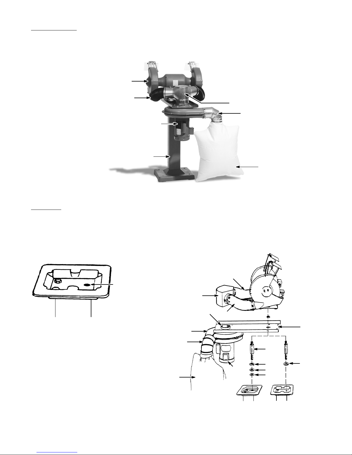
Grinder (rear view)
Flexible Collection Hose
Air Control Valve
Elbow
Motor
Pedestal
Dust Bag
Installation When you receive your control, there are several things you should do immediately.
1. Observe the condition of the shipping container and report any damage immediately to
the commercial carrier that delivered the product.
2. Verify that the part number you received is the same as the part number listed on your
purchase order.
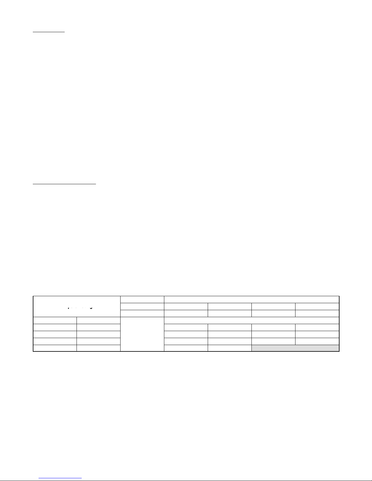
Figure 1 Figure 2
Hose
Remove Bolt
Air Control Valve
Front
Pedestal
Blower Exhaust Outlet
Blower Unit Inlet
Hose
Bracket
Elbow
Stud
L.W.
Dust Bag
Motor
Fig. 2A
(GA20)
L.W.
F. W.
F. W.
Fig. 2B
(GA16)
2 MN908
Page 3
Installation Continued
Ampere Rating
3. Bolt pedestal securely to floor. Pedestal must be securely mounted to floor to prevent tip
4. Remove the pedestal assembly bolt (Figure 1) located in top mounting plate.
5. Replace pedestal assembly bolt with stud and washers supplied with the dust control
6. Mount dust control bracket over stud with motor on bottom side, see Figure 2. Align
7. Mount the double–inlet air control valve to the inlet of the blower unit and secure at base
8. Attach elbow to exhaust outlet of blower.
9. Attach dust bag to elbow with clamp supplied.
Electrical Instructions
Single phase dust control units are rated dual voltage. Some single phase dust control units
are equipped with cord and grounding type plug for 115 volts. To use with a different voltage,
see instructions provided to make wiring changes. All attachment plugs and any receptacles
must be replaced with devices rated for the voltage for which the dust control unit is
reconnected. For your safety, be certain dust control unit is properly grounded. Table 1
indicates the minimum wire size. Be sure to comply with NEC and local wiring codes.
Three phase dust control units are normally dual voltage and must be wired for the proper
voltage and rotation direction (connections are inside conduit box). Connect phase sequence
so that the wheel moves down toward top surface of tool rest as viewed from front of dust
control unit. Wheel must rotate toward tool rest. Be sure all electrical connections are secured
and properly insulated. For your safety, be certain dust control unit is properly grounded.
Table 1 indicates the minimum wire size. Be sure to comply with NEC and local wiring codes.
hazard.
unit (see Figure 2). Use “Fig. 2A” for GA20 pedestal and “Fig. 2B” for GA16 pedestal.
Tighten the stud securely into the pedestal.
mounting holes in bracket with those in pedestal. Secure bracket to stud with nut
supplied. Proceed to mount grinder to pedestal by using proper holes in pedestal and
installing mounting bolts supplied.
of air control valve. Attach a hose (supplied with unit) to each inlet and to each grinder
exhaust outlet. Secure both ends of hoses with clamps supplied.
Ampere Rating
More Than Not More Than AWG
0 6 18 16 16 14
6 10 18 16 14 12
10 12 16 16 14 12
12 16 14 12 Not Recommended
Table 1 Minimum Gauge Wire Size
Volts Total Length of Cord (Cord + Extension, in Feet)
115V 25 50 100 150
230V 50 100 200 300
3MN908
Page 4

Grounding Instructions
WARNING: Be sure the system is properly grounded before applying power. Do not apply power before
you ensure that grounds are connected. Electrical shock can cause serious or fatal injury.
Follow the National Electrical Code (NEC) and local codes for the safe installation of this
equipment.
1. All grounded, cord–connected dust control units:
In the event of a malfunction or breakdown, grounding provides a path of least
resistance for electric current to reduce the risk of electric shock. This dust control unit is
equipped with an electric cord having an equipment–grounding conductor and a
grounding plug. The plug must be plugged into a matching outlet that is properly
installed and grounded in accordance with all local codes and ordinances. Do not
modify the plug provided. If it will not fit the outlet, have the proper outlet installed by a
qualified electrician.
Improper connection of the equipment–grounding conductor can result in a risk of
electric shock. The “Green” insulated wire (with or without yellow stripes) is the
equipment–grounding conductor. If repair or replacement of the electric cord is
necessary , do not connect the equipment–grounding conductor to a live terminal. Check
with a qualified electrician or serviceman if the grounding instructions are not completely
understood, or if in doubt as to whether the tool is properly grounded.
Use only 3–wire extension cords that have 3–prong grounding plugs and 3–pole
receptacles that accept the tool’s plug.
Repair or replace damaged or worn cord immediately.
2. Grounded, cord–connected dust control units intended for use on a supply circuit having
a nominal rating less than 150 volts:
This dust control unit is intended for use on a circuit that has an outlet that looks like the
one illustrated n Figure A. The tool has a grounding plug that looks like the plug
illustrated in Figure A. A temporary adapter, which looks like the adapter illustrated in
Figures B and C, may be used (except in Canada) to connect this plug to a 2–pole
receptacle as shown in Figure B if a properly grounded outlet is not available. The
temporary adapter should be used only until a properly grounded outlet can be installed
by a qualified electrician. The green–colored rigid ear, lug, etc. extending from the
adapter must be connected to a permanent ground such as a properly grounded outlet
box.
3. Permanently connected dust control units:
This dust control unit should be connected to a grounded, metal, permanent wiring
system; or to a system having an equipment–grounding conductor.
Figure A
Grounding
Blade
4 MN908
Cover of
Grounded
Outlet Box
Cover of
Grounded
Outlet Box
Figure B Figure C
Adapter
Grounding
Means
Page 5
Operation
Dust
Dust
W ARNING: Do not operate this dust control unit until you are sure that you are completely familiar
with the safe operation of the dust control unit. Improper use can lead to severe injury.
This manual defines proper use of this equipment. Before using this equipment for any
other use, please consult Baldor. Contact Baldor if you do not understand any procedure
or operation concerning this dust control unit or this manual.
Before operating the dust control unit, be sure that all parts are in place. Check the grinder
that is connected to the dust control unit to be sure it is in safe operating condition. Replace
any damaged or missing parts. Do not operate grinder or dust collector with damaged or
missing parts.
W ARNING: Do not use dust control unit in the presence of potentially combustible materials. Keep all
combustible materials and flammable vapors away from dust control unit.
The dust control unit is for collecting dry material. Many materials in dust form are
combustible. Check material safety data sheet. If material is potentially combustible, do not
use with this dust control unit.
W ARNING: Do not operate the dust control unit/grinder with the dust bag removed. Debris that may
come from an open exhaust outlet can be a hazard to nearby persons or equipment.
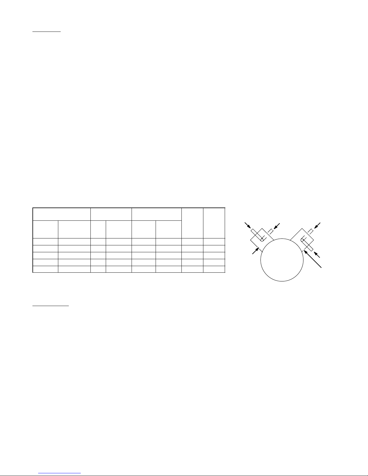
Air Flow Control
The air flow is directed to the wheels by adjusting the air control valves. To meet OSHA
requirements, it is necessary to direct the air flow to the wheels, see Figure D. For “open”
and “closed” position of air control valves, see Figure E. Close the air control valve to the
unused wheel, open the air control valve to the wheel being used.
Valve
Air Control
Inlet Housing
Figure E
Closed
Open
Air Control
Valve
Closed
Inlet
Figure D
Catalog No.
115
1Phase
60 Hz
DC7 DC7-3 7″ 1″ 440 220 ARB-1
DC8 DC8-3 8″ 1″ 440 220 ARB-1
DC10 DC10-3 10″ 1″ 440 390* ARB-1
DC12 DC12-3 12″ 2″ 440 390* ARB-1
DC14 DC14-3 14″ 3″ 700 590* ARB-2 1
* Adjust air control valves to direct total air flow to wheel being used. This is to meet OSHA air flow requirements.
Close the air control valve to the unused wheel, open the air control valve to the wheel being used.
** From ventilation section 1910.04 Table G-4, Federal register, Vol. #202.
208-230/460
3 Phase
60 Hz
Grinding Wheel
Maximum Size
Dia. Width Capacity
Air Flow*
ft3 per minute
OSHA**
Required
per wheel
Bag
HP
Control
Motor
1
/
2
1
/
2
1
/
2
1
/
2
Open
Air Control
Inlet
Maintenance
WARNING: Prevent electrical shock hazard and accidental machine operation. Always disconnect dust
control unit from the power source before servicing, changing dust bag or maintenance.
Caution: Do not wash the dust bag. Washing the bag will remove flame–retardant treatment.
S Motor and bearings are lubricated for life and do not require additional lubrication.
S The dust bag and hoses connecting the dust control to the grinder should be cleaned
occasionally (as needed).
S Wearing safety glasses and dust mask, remove the dust bag and shake the dust into a
suitable container for disposal. Dispose of the dust in accordance with material safety
data sheets, local codes and ordinances.
S Do not wash the bag. Washing the bag will remove flame–retardant treatment.
S Re–install the dust bag after cleaning.
S Replacement parts are available from Baldor distributors. Provide catalog number and
specification number from nameplate of the Baldor product, plus the part description.
S Do not discard this manual. Keep it in a convenient location for reference.
5MN908
Page 6

6 MN908
Page 7

7MN908
Page 8

LIMITED WARRANTY
Unless otherwise provided, Baldor grinders are warranted against defects in Baldor workmanship and
materials for a period of Thirty–Six months. All warranty claims must be submitted to a Baldor repair facility
prior to the expiration of the warranty period. Baldor shall have no responsibility or liability for any defect,
latent or otherwise, discovered after the expiration of the warranty period provided herein. Extended
warranties are available for certain Baldor products. These warranties are described in Baldor’s catalog and
other sales literature. Extended warranties are subject to the terms and conditions of this Limited Warranty
as modified by the additional terms of the extended warranty . If a Baldor product is defective due to Baldor
workmanship or materials and the defect occurs during the warranty period, then Baldor will either repair the
product or replace it with a new one, whichever Baldor believes to be appropriate under the circumstances.
Warranty service is available for all Baldor products from Baldor’s Customer Service Department in Fort
Smith, Arkansas, and from Baldor repair facilities. A list of Baldor’s repair facilities may be obtained by
contacting Baldor at: Baldor Electric Company, 5711 R.S. Boreham, Jr. St., Fort Smith, Arkansas,
479–646–4711 (phone), 479–648–5792 (fax). All Baldor products requiring warranty service shall be
transported or shipped freight pre–paid, at the risk of the party requiring warranty service, to Baldor ’s
Customer Service Department in Fort Smith, Arkansas or to a Baldor repair facility. Written notification of the
alleged defect in addition to a description of the manner in which the Baldor grinder is used, and the name,
address and telephone number of the party requiring warranty service must be included. Baldor is not
responsible for removal and shipment of the Baldor product to the service center nor for the reinstallation of
the Baldor product upon its return to the party requiring warranty service. Customers who are unable to take
or ship the Baldor product to a Baldor repair facility, or who desire a repair to be made by other than a Baldor
repair facility, should contact Baldor’s Customer Service Department at 479–646–4711. Repair by anyone
other than a Baldor repair facility must be approved in writing by Baldor in advance of such service.
Problems with Baldor products can be due to improper maintenance, faulty installation, non–Baldor
additions or modifications, or other problems not due to defects in Baldor workmanship or materials. If a
Baldor repair facility determines that the problem with a Baldor product is not due to defects in Baldor
workmanship or materials, then the party requiring warranty service will be responsible for the cost of any
necessary repairs. Parties requiring warranty service not satisfied with a determination that a problem is
outside of warranty coverage should contact Baldor’s Customer Service Department at 479–646–4711 for
further consideration.
EXCEPT FOR THE EXPRESS WARRANTY SET FORTH ABOVE, BALDOR DISCLAIMS ALL OTHER
EXPRESS AND IMPLIED WARRANTIES INCLUDING THE IMPLIED WARRANTIES OF FITNESS FOR A
PARTICULAR PURPOSE AND MERCHANTABILITY. NO OTHER WARRANTY, EXPRESS OR
IMPLIED, WHETHER OR NOT SIMILAR IN NATURE TO ANY OTHER WARRANTY PROVIDED HEREIN,
SHALL EXIST WITH RESPECT TO THE GOODS SOLD UNDER THE PROVISIONS OF THESE TERMS
AND CONDITIONS. ALL OTHER SUCH WARRANTIES ARE HEREBY EXPRESSLY WAIVED BY THE
BUYER. UNDER NO CIRCUMSTANCES SHALL BALDOR BE LIABLE OR RESPONSIBLE IN ANY
MANNER WHATSOEVER FOR ANY INCIDENTAL, CONSEQUENTIAL OR PUNITIVE DAMAGES, OR
ANTICIPATED PROFITS RESULTING FROM THE DEFECT, REMOVAL REINSTALLATION, SHIPMENT
OR OTHERWISE.
This is the sole warranty of Baldor and no other affirmations or promises made by Baldor shall be deemed to
create an express or implied warranty. Baldor has not authorized anyone to make any representations or
warranties other than the warranty contained herein.
P.O. Box 2400 Ft. Smith, AR 72902–2400
(479) 646–4711 Fax (479) 648–5792
Baldor Electric Company
8 MN908
www.baldor.com
Printed in USA
PS500 9/03
 Loading...