

Baldor DBSC105-AAA-1, DBSC102-AAA, DBSC102-AAA-1, DBSC105-AAA Installation And Operating Manual
Page 1

AC Servo Drive
$25.00
DBSC 100 Series
AC Servo Control
Installation and Operating Manual
9/96MN1229
Page 2

Table of Contents
Section 1
Introduction and Conformity 1–1.
Introduction 1–1
Conformity 1–1
Limited Warranty 1–2.
Safety Notice 1–3.
Precautions 1–3
. . . . . . . . . . . . . . . . . . . . . . . . . . . . . . . . . . . . . . . . . . . . .
. . . . . . . . . . . . . . . . . . . . . . . . . . . . . . . . . . . . . . . . . . . . . .
. . . . . . . . . . . . . . . . . . . . . . . . . . . . . . . . . . . . . . . .
. . . . . . . . . . . . . . . . . . . . . . . . . . . . . . . . . . . . . . . . . . .
. . . . . . . . . . . . . . . . . . . . . . . . . . . . . . . . . . . . . . . . . . . . .
Section 2
Specifications 2–1.
Identification 2–1
. . . . . . . . . . . . . . . . . . . . . . . . . . . . . . . . . . . . . . . . . . .
. . . . . . . . . . . . . . . . . . . . . . . . . . . . . . . . . . . . . . . . . . . . .
General Specifications 2–2.
Signal Levels 2–4.
Regeneration 2–5
. . . . . . . . . . . . . . . . . . . . . . . . . . . . . . . . . . . . . . . . . . .
. . . . . . . . . . . . . . . . . . . . . . . . . . . . . . . . . . . . . . . . . . . .
Operating Conditions 2–5.
Optional 24VDC Input 2–5.
Section 3
Installation 3–1.
Overview 3–1
. . . . . . . . . . . . . . . . . . . . . . . . . . . . . . . . . . . . . . . . . . . . . .
. . . . . . . . . . . . . . . . . . . . . . . . . . . . . . . . . . . . . . . . . . . . . . . .
Location and Mounting 3–1.
Altitude Derating 3–1.
. . . . . . . . . . . . . . . . . . . . . . . . . . . . . . . . . . . . . . . .
Temperature Derating 3–1.
Overload Protection 3–2.
. . . . . . . . . . . . . . . . . . . . . . . . . . . . . . . . . . . . .
Wiring Consideration 3–2.
Protective Devices 3–2.
Power Disconnect 3–2.
. . . . . . . . . . . . . . . . . . . . . . . . . . . . . . . . . . . . . .
. . . . . . . . . . . . . . . . . . . . . . . . . . . . . . . . . . . . . . .
AC Power Connections 3–2.
Motor Wiring 3–4.
. . . . . . . . . . . . . . . . . . . . . . . . . . . . . . . . . . . . . . . . . . . .
Control Signal Wiring 3–4.
Active High Definition 3–4.
Active Low Definition 3–4.
Command Input 3–7.
. . . . . . . . . . . . . . . . . . . . . . . . . . . . . . . . . . . . . . . . .
. . . . . . . . . . . . . . . . . . . . . . . . . . . . . .
. . . . . . . . . . . . . . . . . . . . . . . . . . . . . . . . . . .
. . . . . . . . . . . . . . . . . . . . . . . . . . . . . . . . . . . .
. . . . . . . . . . . . . . . . . . . . . . . . . . . . . . . . . . . .
. . . . . . . . . . . . . . . . . . . . . . . . . . . . . . . . . . .
. . . . . . . . . . . . . . . . . . . . . . . . . . . . . . . . . . . .
. . . . . . . . . . . . . . . . . . . . . . . . . . . . . . . . . . . .
. . . . . . . . . . . . . . . . . . . . . . . . . . . . . . . . . .
. . . . . . . . . . . . . . . . . . . . . . . . . . . . . . . . . . . .
. . . . . . . . . . . . . . . . . . . . . . . . . . . . . . . . . . . .
. . . . . . . . . . . . . . . . . . . . . . . . . . . . . . . . . . . .
MN1229
TOC–1
Page 3

Section
REGEN Resistor 3–8.
Resolver Wiring 3–8.
Encoder Output 3–9.
Serial Interface Wiring 3–10.
Optional Control Signal Wiring 3–11.
Fault Relay Output 3–11.
24VDC External Power Source 3–11.
Control Inputs 3–12.
Control Outputs 3–12.
Electronic Handwheel (Optional) 3–13.
Cable Preparation 3–13.
Cable Connection 3–14.
. . . . . . . . . . . . . . . . . . . . . . . . . . . . . . . . . . . . . . . .
. . . . . . . . . . . . . . . . . . . . . . . . . . . . . . . . . . . . . . . . .
. . . . . . . . . . . . . . . . . . . . . . . . . . . . . . . . . . . . . . . .
. . . . . . . . . . . . . . . . . . . . . . . . . . . . . . . . . . .
. . . . . . . . . . . . . . . . . . . . . . . . . . . .
. . . . . . . . . . . . . . . . . . . . . . . . . . . . . . . . . . . . . .
. . . . . . . . . . . . . . . . . . . . . . . . . . . .
. . . . . . . . . . . . . . . . . . . . . . . . . . . . . . . . . . . . . . . . . .
. . . . . . . . . . . . . . . . . . . . . . . . . . . . . . . . . . . . . . . . .
. . . . . . . . . . . . . . . . . . . . . . . . . .
. . . . . . . . . . . . . . . . . . . . . . . . . . . . . . . . . . . . . . .
. . . . . . . . . . . . . . . . . . . . . . . . . . . . . . . . . . . . .
Section 4
System Setup 4–1.
Overview 4–1
DIP Switch Settings 4–1.
Jumper Settings 4–3.
Power Up 4–4.
First Time Power Up 4–4.
. . . . . . . . . . . . . . . . . . . . . . . . . . . . . . . . . . . . . . . . . . . .
. . . . . . . . . . . . . . . . . . . . . . . . . . . . . . . . . . . . . . . . . . . . . . . .
. . . . . . . . . . . . . . . . . . . . . . . . . . . . . . . . . . . . .
. . . . . . . . . . . . . . . . . . . . . . . . . . . . . . . . . . . . . . . .
. . . . . . . . . . . . . . . . . . . . . . . . . . . . . . . . . . . . . . . . . . . . . .
. . . . . . . . . . . . . . . . . . . . . . . . . . . . . . . . . . . . .
Section 5
Troubleshooting 5–1.
Overview 5–1
DB LED 5–2.
. . . . . . . . . . . . . . . . . . . . . . . . . . . . . . . . . . . . . . . . . . . . . . . .
. . . . . . . . . . . . . . . . . . . . . . . . . . . . . . . . . . . . . . . . . . . . . . . .
. . . . . . . . . . . . . . . . . . . . . . . . . . . . . . . . . . . . . . . . .
Section 6
Drawings 6–1.
DBSC Dimensions 6–1.
DBSC 100 Connector Descriptions 6–2.
Mounting Hole Location 6–3.
. . . . . . . . . . . . . . . . . . . . . . . . . . . . . . . . . . . . . . . . . . . . . . . .
. . . . . . . . . . . . . . . . . . . . . . . . . . . . . . . . . . . . . .
. . . . . . . . . . . . . . . . . . . . . . . .
. . . . . . . . . . . . . . . . . . . . . . . . . . . . . . . . . .
TOC–2
MN1229
Page 4

Section 1
Introduction and Conformity
Introduction
The Baldor Series Controls represent the latest technology in microprocessor
based motor controls. The user programmable parameters available in every
control provides the ability to customize the control to most any application.
Baldor has tried to ensure that the information in this manual is correct at the
time of printing. The information is subject to change without prior notice.
This document is copyright by Baldor and is supplied with the understanding
that it will not be reproduced or disclosed in whole or in part, without the
express permission of Baldor.
Conformity
This product is only for use in industrial applications as described in EN 60204
and VDE 0160. This means use DBSC100 in stationary ground based
applications only
within the meaning of “Safety law of appliance”, “EMC Law” or “Machine
directive”. It is the responsibility of the user to verify that the equipment the
DBSC 100 is used in complies with all applicable regulations.
The DBSC 100 Series AC Servo Control is intended for use in industrial
installations. These controls are designed for applications that require speed
control of three phase AC Servo motors.
The DBSC 100 conforms to the following standards:
. It is a component only and is not intended for immediate use
DIN VDE 0100
DIN VDE 01
DIN VDE 0160
DIN IEC 326
EN 60529
MN1229
10
Power installations with nominal voltages
Dimensioning of clearance tolerances.
Electronic equipment for use in electrical power
installations.
Design and use of printed circuit boards.
Degrees of protection provided by enclosure.
≤ 1000 VAC.
1–1
Page 5

Section
Limited Warranty
For
a period of one (1) year from the date of
or replace without charge controls which our examination proves to be defective in
material
or workmanship. This warranty is valid if the unit has not been tampered
with by unauthorized persons, misused, abused, or improperly installed and has
been used in accordance with the instructions and/or ratings supplied. This
warranty is in lieu of any other warranty or guarantee expressed or implied.
BALDOR
removal),
or
property caused by items of our manufacture or sale. (Some states do not allow
shall not be held responsible for any expense (including installation and
inconvenience, or consequential damage, including injury to any person
exclusion or limitation of incidental or consequential damages, so the above
exclusion may not apply.) In any event, BALDOR’s total liability, under all
circumstances,
purchase
shall not exceed the full purchase price of the control. Claims for
price refunds, repairs, or replacements must be referred to BALDOR
all pertinent data as to the defect, the date purchased, the task performed by the
control,
and the problem encountered. No liability is assumed
such as fuses.
Goods
may be returned only with written notification including a BALDOR
Authorization Number and any return shipments must be prepaid.
original purchase, BALDOR will repair
with
for expendable items
Return
1–2
MN1229
Page 6

Section
Safety Notice
This equipment contains high voltage. Electrical shock can cause serious or
fatal injury. Only qualified personnel should attempt the start-up procedure or
troubleshoot this equipment.
This equipment may be connected to other machines that have rotating parts or
parts that are driven by this equipment. Improper use can cause serious or
fatal injury. Only qualified personnel should attempt the start-up procedure or
troubleshoot this equipment.
PRECAUTIONS
WARNING: Do not touch any circuit board, power device or electrical
connection before you first ensure that power has been
disconnected and there is no high voltage present from
this equipment or other equipment to which it is
connected. Electrical shock can cause serious or fatal
injury. Only qualified personnel should attempt the
start-up procedure or troubleshoot this equipment.
WARNING: Be sure that you are completely familiar with the safe
operation of this equipment. This equipment may be
connected to other machines that have rotating parts or
parts that are controlled by this equipment. Improper use
can cause serious or fatal injury. Only qualified personnel
should attempt the start-up procedure or troubleshoot this
equipment.
WARNING: Be sure all wiring complies with the National Electrical
Code and all regional and local codes. Improper wiring
may result in unsafe conditions.
WARNING: Be sure the system is properly grounded before applying
power. Do not apply AC power before you ensure that all
grounding instructions have been followed. Electrical
shock can cause serious or fatal injury.
MN1229
1–3
Page 7

Section
WARNING: Do not remove cover for at least five (5) minutes after AC
power is disconnected to allow capacitors to discharge.
Dangerous voltages are present inside the equipment.
Electrical shock can cause serious or fatal injury.
WARNING: Improper operation of control may cause violent motion of
the motor shaft and driven equipment. Be certain that
unexpected motor shaft movement will not cause injury to
personnel or damage to equipment. Peak torque of
several times the rated motor torque can occur during
control failure.
WARNING: Motor circuit may have high voltage present whenever AC
power is applied, even when motor is not rotating.
Electrical shock can cause serious or fatal injury.
Caution: To prevent equipment damage, be certain that the
electrical service is not capable of delivering more than
the maximum line short circuit current amperes listed in
this manual.
Caution: To prevent equipment damage, be certain that the input
power has correctly sized protective devices installed as
well as a power disconnect.
Caution: To prevent equipment damage, DO NOT connect a 24VDC
source to terminal strip X2 if the 24 Volt option is not
installed. If you apply 24VDC to X2 without the option, the
control will be damaged.
1–4
MN1229
Page 8
Section 2
Specifications
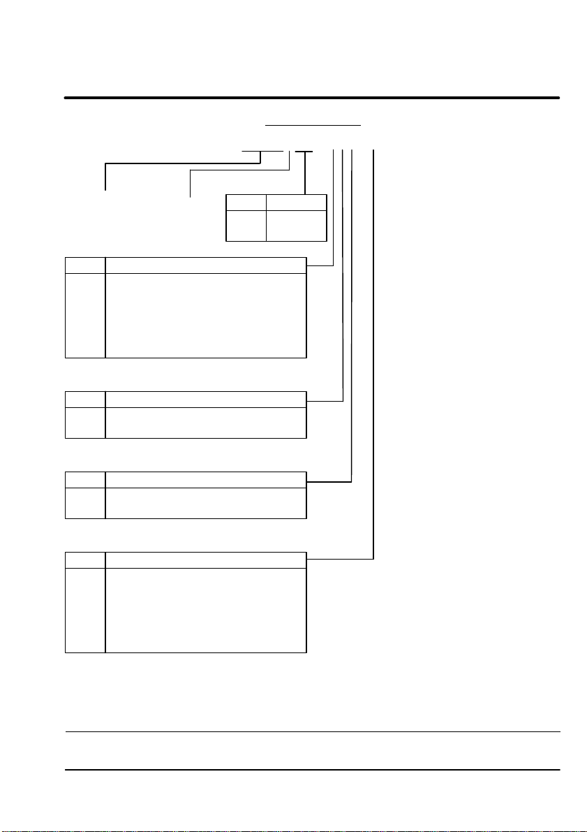
Identification
DBSC 1XX - XXX - X
Digital
Baldor
Series
Servo Control
Code Input
A
B
E
F
Code
A
B
Code
A
B
Code
Blank
1
2
3
Control Options
Pulse & Direction with RS-232
Pulse & Direction with RS-422/RS485
Electronic Handwheel (Pulse Follower)
with RS-232
Electronic Handwheel (Pulse Follower)
with RS-422/RS485
Feedback Options
Standard Resolver
Encoder
Field Bus Options
None
CAN Bus
Input Control Options
Standard 230 V
1
15 V
AC 1O Input Power
Optional external 24 VDC Logic Input
(Customer Provided)
1
15 V
AC 1O Input Power and
External 24 VDC Logic Input
AC Input Power
Code Current
02052.5 Amps
5 Amps
MN1229
2–1
Page 9

Section
General Specifications - 230VAC
Description Unit DBSC102-AAA DBSC105-AAA
Input Voltage Range
(230V
AC 1O Nominal)
Input Frequency Hz 50/60 ±5%
Nominal Output Bus (Range)
Nominal Current (
Peak Phase Current (±10%); 2.5s
.5s
Nominal Output Power
Efficiency % >97
Minimum Load Inductance mH 400
Nominal Switching Frequency KHz 8.5
Mounting – Panel
Overall Dimensions
Weight
Operating Altitude
Operating Temperature °C
Rated
Storage T
±10%) A
emperature °C –25 to +70
VAC
VDC
RMS
±
A
RMS
KVA 1.01 2.17
in (mm)
lbs (Kg)
Feet
(Meters)
2.65x6.81x6
(67.5x173x152.5)
2.73 (1.24)
(without heatsink)
To 3300 feet (1000 meters).
Above 3300 ft, derate 11% per
220 - 250
320 (50-350)
2.5 5
5 10
3300ft (1000m).
+5 to 40
1
3.6x6.8x6
(92.5x173x152.5)
4.69 (2.13)
(with heatsink)
1
DBSC 105 with additional heatsink.
All values at ambient temperature of 25°C unless otherwise stated.
2–2
MN1229
Page 10

Section
General Specifications - 115VAC
Description Unit DBSC102-AAA-1 DBSC105-AAA-1
Input Voltage Range
(115V
AC 1O Nominal)
Input Frequency Hz 50/60 ±5%
Nominal Output Bus (Range)
Nominal Current (
Peak Phase Current (±10%); 2.5s
.5s
Nominal Output Power
Efficiency % >97
Minimum Load Inductance mH 400
Nominal Switching Frequency KHz 8.5
Mounting – Panel
Overall Dimensions
Weight
Operating Altitude
Operating Temperature °C
Rated
Storage T
±10%) A
emperature °C
VAC
VDC
RMS
±
A
RMS
KVA 1.01 2.17
in (mm)
lbs (Kg)
Feet
(Meters)
2.65x6.81x6
(67.5x173x152.5)
2.73 (1.24)
(without heatsink)
To 3300 feet (1000 meters).
Above 3300 ft, derate 11% per
97 - 125
320 (50-350)
2.5 5
5 10
3300ft (1000m).
+5°C to 40°C
–25°C
1
3.6x6.8x6
(92.5x173x152.5)
4.69 (2.13)
(with heatsink)
to +70
°C
1
DBSC 105 with additional heatsink.
All values at ambient temperature of 25°C unless otherwise stated.
MN1229
2–3
Page 11

Section
Signal Levels
Description Unit DBSC 102 DBSC 105
Command Input
Command Signal Resolution bits 12
A/D Conversion Rate
Control Inputs - X3-6, X3-7, X3-9, X3-10,
X3-1
Feedback System – Resolver
Feedback Resolution V
Resolver Pole Paris
Resolver Winding Ratio
Encoder Output – RS422
Encoder Resolution ppr 512 / 10241 / 2048 / 4096
Pulse & Direction Input
Maximum Input Frequency KHz 500
Optional Handwheel Input (Pulse Follower)
Maximum Input Frequency KHz 500
Communications Interfaces
Data Communications Rate
1, X3-12, X3-13, X3-16, X3-17
elocity
V
V
≤1500 RPM
elocity
≤6000 RPM
elocity > 6000 RPM
VDC ±10
msec 476
VDC
bits 16
14
12
– 1
– RS422
– RS422
(Encoder interface - A & B)
–
Baud 9600 (Fixed)
+12 to +29
0.5
(Galvanically Isolated)
RS232 / 422 / 485
(Not galvanically Isolated)
1
Factory Setting.
2–4
MN1229
Page 12

Section
Regeneration
Description Unit DBSC 102 DBSC 105
Maximum REGEN Switching Current
Maximum Load Inductance mH 100
REGEN Resistor for
DBSC 10X-AAA (230V
REGEN Resistor for
DBSC 10X-AAA-1 (1
Continuous REGEN Power with
230V
AC (1
15V
AC) Input V
REGEN Power
AC)
15VAC)
oltage
A 7
– RG56
– RG27
Watts 44
Watt-Sec 430
Operating Conditions
Description Unit DBSC 102 DBSC 105
Ambient Operating T
Humidity % 10 to 90 RH Non-Condensing
Altitude m 1000
Shock –
Vibration –
Class of Protection
emperature °C
+5 to 40
(According to DIN40 040,
10G (DIN IEC 68-2-6/29)
1G (DIN IEC 68-2-6/29)
–
IP20 (DIN40 050/ IEC 144
class F)
Optional 24VDC Input (Optional - Must be ordered separately)
Description Unit DBSC 102 DBSC 105
Input V
oltage Range VDC
Input Ripple V
Input Current (@24VDC)
Surge Current (at Power On for
DC Bus V
with 24V option
MN1229
oltage % ±10
≤100msec) A
oltage absolute Min (Max) values
A
RMS
RMS
VDC
20 to 30
1.75
4
0 (350)
2–5
Page 13

Section 3
Installation
Overview
This section describes the proper mounting and wiring procedure for the Baldor
Series DBSC 100 AC Servo Control. If problems arise after installation, please
refer to the Diagnostics and Troubleshooting section of this manual.
Location and Mounting
CAUTION: Avoid locating control immediately above or beside heat
generating equipment, or directly below water or steam
pipes.
CAUTION: Avoid locating control in the vicinity of corrosive
substances or vapors, metal particles and dust.
Select a mounting surface for the control that will allow the control to be
mounted in a vertical position (with connector X1 at the top) using the mounting
hole(s) provided. Mounting hole location is shown in Section 6 of this manual.
The area selected should allow air to freely circulate around the control. This is
very important to maintain proper heat dissipation. Provide at least six inches
of clearance top and bottom for maximum cooling efficiency.
Refer to the Section 6 Mounting Hole Location diagram and locate and drill the
mounting hole(s) and mount the control.
Altitude Derating
Control ratings apply to 3300 feet (1000 meters) altitude without derating
required. For installations at higher altitudes derate the continuous and peak
output currents of the control by 11% for each 3300 feet (1000 meters) above
3300 feet.
Temperature Derating
Control ratings apply from 5°C to 40°C. Maximum ambient temperature is 40°C.
MN1229
3–1
Page 14

Section
Overload Protection
Baldor Controls feature UL approved motor overload protection suitable for
motors that consume at least 50% of the output rating of the control. Other
governing agencies such as NEC (National Electric Code) may require separate
over current protection. The installer of this equipment is responsible for
complying with NEC guidelines and CE directives (Conformite Europeene) and
applicable local codes that govern wiring protection, grounding, disconnects and
other current protection.
Wiring Consideration
All logic and control connections are made at the connectors shown in Figure
3-1. All external wires for the control should be run in a conduit that is separate
from power wiring. The use of shielded wire is recommended for all control
wiring.
Protective Devices
Be sure a suitable input power protection device is installed.
Slow
Blow Fuse:
Each DBSC must be fused separately. Recommended fuse
rating is determined as follows:
I
= 1.25 X I
fuse
nominal
Power Disconnect
A power disconnect should be installed between the input power source and the
DBSC for a fail safe method to disconnect power. The control will remain in a
powered-up condition until all input power is removed from the control and the
internal bus voltage has depleted.
AC Power Connections
Figure 3-1 shows the connector locations.
1. Connect the incoming AC power wires from the protection devices as
follows:
Line 1 to connector X1 pin 2 (label “L”).
Line 2 to connector X1 pin 3 (label “N”).
2. Connect earth ground to X1 pin 1 (labeled “PE”) of the control. Be sure to
comply with local codes.
3–2
MN1229
Page 15

Section
Figure 3-1 DBSC 100 Connector Locations
Power
Connector
24VDC
Supply
Input
X1
PE
L
N
U
V
W
DB+
DB–
X2
24v
0v
DB
On
AS1
Off/On
Ready
Monitor
1
2
3
4
5
6
7
8
X
9
X
6
Encoder
Input
Serial
Interface
= Optional
Hardware
MN1229
X
3
X
7
X
8
Encoder
Output
Resolver
Input
3–3
Page 16

Section
Motor Wiring
Connect the motor leads as follows:
1. Connect motor phase U to X1-U.
2. Connect motor phase V to X1-V.
3. Connect motor phase W to X1-W.
Control Signal Wiring
All wiring from external devices to the control are made at the connectors
shown in Figure 3-1.
The inputs at X3 pins 7, 9, 10, 11 and 12 can be wired for active high or active
low conditions. Pin 7 is the CREF (Control Input Reference) point.
Active High Definition
If the Control Inputs are to be wired as Active High, CREF is connected to
GND. When a control input is at +24VDC (range +12VDC to +29VDC), it is
active and when it is at GND it is inactive. Figure 3-2 shows this relationship.
Active Low Definition
If the Control Inputs are to be wired as Active Low, CREF is connected to
+24VDC (range +12VDC to +29VDC). When a control input is at GND, it is
active and when it is at +24VDC it is inactive. Figure 3-2 shows this
relationship.
Table 3-1 Control Inputs
Signal Connector Active
Enable X3-9
CW Limit
CCW Limit
Hold X3-12
3–4
X3-10
X3-11
Condition
Control Enable
CW Rotation Enabled
CCW Rotation Enabled
Hold function is Active
Inactive Condition
Control Disabled
CW Rotation Disabled
CCW Rotation Disabled
Hold function is not
active
MN1229
Page 17

Section
Active
Low
GND
ext
(Sink)
+24VDC
Control Signal Wiring Continued
Figure 3-2 Active HIGH/LOW Relationship
Active High
V
ext
(Source)
GND
X3
Pin 7 - CREF
GND
+24VDC
Pin 9 - Enable
Pin 10 - CW
Pin 1
1 - CCW
Pin 12 - Hold
Pin 13 - Reset
Pin 16 - Machine Input 1
Pin 17 - Machine Input 2
Note: These pins are shown wired together. Although this can be done,
each input is usually connected to a switch for individual control of
each input condition. Pins 16 and 17 are optional inputs and are
described later in this section.
A typical wiring control diagram is shown in Figure 3-3.
1. Connect the CREF signal wire to X3-7.
2. Connect the Enable signal wire to X3-9.
3. Connect the CW Limit signal wire to X3-10.
4. Connect the CCW Limit signal wire to X3-11.
5. Connect the Hold signal wire to X3-12 (optional).
6. Connect the Reset (Fault Reset) signal wire to X3-13 (optional).
The Reset signal (Fault Reset) can only reset the following fault types: Over
voltage, Under voltage, Resolver fault, or Control Temperature fault.
Note: Current input for each control input X3-9 to X3-17 is
Iin=10mA maximum (for each input).
MN1229
3–5
Page 18

Section
Control Signal Wiring Continued
Figure 3-3 Wiring Control Diagram (X3)
X3
Note:
Shown as Active High.
Optional
External
Power
Source
GND
+24VDC
CREF
Enable
CW Limit
CCW Limit
Hold
Reset
CMD (+)
CMD (–)
AGND
Fault (+)
Fault (–)
CIV
Ground Return
Pulse Input
Direction Input
Machine Input 1
Machine Input 2
1
2
3
4
5
6
7
8
9
10
11
12
13
14
15
16
17
3–6
Machine Output 1
Machine Output 2
Drive OK
18
19
20
MN1229
Page 19

Section
Control Signal Wiring Continued
Command Input
The Analog Input at X3 pins 1, 2, and 3 can be wired for single ended or
differential input operation. Figure 3-4 shows these configurations.
Figure 3-4 Command Input Mode
X3
X3
CMD (+)
CMD
(–)
Differential Input
1
2
3AGND
CMD
1
2
3AGND
Single Ended Input
1. Determine if your application requires Single Ended Input (Step 2) or
Differential Input (Step 3) Command Signal wiring.
2. For Single Ended Input wiring:
A. Connect the CMD input wire to X3-1.
B. Connect the command common (analog ground) wire to X3-3.
C. Connect a jumper wire from X1-3 to X1-2.
3. For Differential Input wiring:
D. Connect the CMD (+) input wire to X3-1.
E. Connect the CMD (–) input wire to X3-2.
F. Connect the command common (analog ground) wire to X3-3.
MN1229
3–7
Page 20

Section
REGEN Resistor
If the motor is connected to a large inertia load that may require rapid
deceleration, an external REGEN resistor must be installed as follows:
1. Connect one wire from the REGEN Resistor to connector X1-7.
2. Connect the other wire from the REGEN Resistor to connector X1-8.
Resolver Wiring
The Resolver interface DB-9 connector is X8 on the DBSC control. Figure 3-5
shows the connector pin numbers and signal names. Use twisted pair shielded
cable with an insulated overall shield.
Figure 3-5 Resolver Interface
X8
REFERENCE+
1
COSINE+
2
SINE+
3
4
GND
5
6
7
8
9
REFERENCE
COSINE –
SINE –
–
1. Connect the Reference + to X8-1 and Reference – to X8-6.
2. Connect Cosine + to X8-2 and Cosine – to X8-7.
3. Connect Sine + to X8-3 and Sine – to X8-8.
4. Connect the Analog Ground wire to X8-5.
3–8
MN1229
Page 21

Section
Encoder Output
The encoder output provides position information to the host position controller.
Use twisted pair shielded cable with an insulated overall shield. Connect the
Encoder Output signals to the positioner as follows: (See Figure 3-6).
Figure 3-6 Encoder Output
X7
Channel A
1
Channel
2
3
4
5
6
7
8
9
1. Connect the Channel A to X7-1 and Channel A to X7-6.
2. Connect the Channel B to X7-2 and Channel B to X7-7.
3. Connect the Channel C to X7-3 and Channel C to X7-8.
4. Connect the GND to X7-5.
B
Channel C
GND
Channel A
Channel B
Channel C
The encoder resolution must be set as described in the software manual.
MN1229
3–9
Page 22

Section
Serial Interface Wiring
Serial Interface
The Serial interface (DB9 connector X6) is used for communication with a PC
(Personal Computer) or other equipment.
RS232 - Not available in model DBSC 10X-BXX.
For the RS232 interface, a standard shielded modem cable can be used for
connection to a PC. If the cable is straight through (pin to pin), a null modem
connector must be used.
These are the only RS232 signals supported by the DBSC control. Mode is
jumper selectable as described in Section 4 of this manual.
RS422/RS485 - Not available in model DBSC 10X-AXX.
RS422/RS485 is a factory installed and jumper selectable in models DBSC
10X-EXX and DBSC 10X-FXX. Mode is jumper selectable as described in
Section 4 of this manual.
Figure 3-7 RS232 Interface
X6 PC
1
2
3
4
5
6
7
8
9
RS232
RD
TD
GND
RTS
CTS
+5VDC
X6 PC
1
2
3
4
5
6
7
8
9
1
2
3
4
5
6
7
8
9
RS422/RS485
(Optional)
TX–
TX+
RX+
RX–
GND
RTS–
RTS+
CTS+
CTS–
1
2
3
4
5
6
7
8
9
Note: The +5VDC at X6-9 can be used to power hand held display
terminals. Maximum rating of this power source is +5VDC at 350mA.
3–10
MN1229
Page 23

Section
Optional Control Signal Wiring
Fault Relay Output (Optional)
A normally closed relay contact is provided at X3-4 and X3-5. This contact can
be used to drive an external fault indicator circuit to indicate a fault condition
has occurred. If a fault occurs the fault must be reset (X3-13). Wire the optional
external fault indicator circuit as follows: (see Figure 3-8).
1. Connect a voltage source to X3-4. (115VAC @ 0.3A or +24VDC @ 0.8A).
2. Connect the relay or circuit load to X3-5.
When a fault occurs, the internal N.C. contact will open and de-energize the
Fault Circuit.
Figure 3-8 Optional External Fault Indicator
X3
4
5
Customer
Fault Circuit
Voltage
Source
Supplied
24VDC External Power Source (Optional)
Caution: To prevent equipment damage, DO NOT connect a 24VDC
source to terminal strip X2 if the 24 Volt option is not
installed. If you apply 24VDC to X2 without the option,
damage to the control will result. Refer to Section 2 of
this manual to identify the model number and determine if
the option is installed.
An external 24 VDC power source can be used as a battery backup feature if
the 24VDC option is installed. This may be identified by the catalog number. If
AC power is lost, the DBSC control circuits are still active.
Connect the external source to connector X2 as follows:
1. Connect the + (Positive) lead to X2-24V.
2. Connect the – (Negative) lead to X2-0V.
MN1229
3–11
Page 24

Section
Optional Control Signal Wiring Continued
Control Inputs (Optional)
These control inputs are optional. Their reference (common) is CREF at X3-7
(see Figure 3-3). The voltage range is +12VDC to +29VDC for these inputs.
They may be used by a PLC or other signal source within your application.
1. Connect the Machine Input 1 (MAI1) signal to X3-16.
2. Connect the Machine Input 2 (MAI2) signal to X3-17.
These inputs are galvanically isolated. Their reference (common) is CGND at
X3-8 of Figure 3-3.
3. Connect the Pulse Input signal to X3-14.
4. Connect the Direction Input signal to X3-15.
Control Outputs (Optional)
Four Opto Isolated outputs are available for “Active Low” (Sink) use.
Connect one or more of the control outputs as follows: (see in Figure 3-9).
1. Connect the Ground Return of the power source to X3-8.
2. Connect a customer provided +24VDC source (range = +12VDC to
+29VDC) to X3-6 the CIV input (Customer Input Voltage).
3. Connect Machine Output 1 (MAO1) X3-18 to PLC.
4. Connect Machine Output 2 (MAO2) X3-19 to PLC.
5. Connect the Drive OK load to X3-20.
Figure 3-9 Optional Control Outputs
X3
Ground Return
8
18
19
20
6
T
o Customer
Provided PLC
CIV *
Machine
Machine Output 2
Output 1
Drive OK
* 24VDC nominal at 100mA minimum.
Note: These outputs are programmable. Refer to software setup manual for
further details.
3–12
MN1229
Page 25

Section
Electronic Handwheel (Optional)
The electronic handwheel (pulse follower) is an optional connection that allows
the control to follow the pulses from an encoder input. This is a factory installed
option and must be ordered with the control. This wiring must be separated
from power wiring. Separate encoder cable by at least 3″ from parallel runs of
power wires. Cross power wires at right angles only.
Cable Preparation
Encoder wiring must be shielded twisted pairs, #22 AWG (0.34mm2) minimum
size, 200′ (61m) maximum, with an insulated overall shield.
DBSC Control End (See Figure 3-10.)
1. Strip the outside jacket approximately 0.375″ (9.5mm) from the end.
2. Solder a #22 AWG (0.34mm2) wire to the braided shield. Carol cable has
a clear Mylar sleeve between the braided shield and the wire bundle.
Belden cable does not have a Mylar sleeve.
3. Connect all shields to X9-13. To do this, solder a “Drain Wire” from each
shield to the wire soldered to the braided shield in step 2.
4. Insulate or tape off ungrounded end of shields to prevent contact with other
conductors or ground.
Encoder End
1. Strip the outside jacket approximately 0.375″ (9.5mm) from the end.
2. Identify each of the four twisted pair and label or use the color codes
shown in Figure 3-10.
3. Insulate or tape off ungrounded end of shields and unused conductors to
prevent contact with other conductors or ground.
CAUTION: Do not connect any shields to the encoder case or motor
frame. Do not connect any shields to ground or another
power supply or damage to the control may result.
MN1229
3–13
Page 26

Section
Electronic Handwheel Continued
Cable Connection
1. Differential Connections Only
Connect the cable Braided Shield to DBSC control connector X9-13.
Signal Name X9 Connector
Channel A
Channel A
Channel B
Channel B
Channel C
Channel C
X9-1 (A)
X9-6 (A)
X9-2 (B)
X9-7 (B)
X9-3 C
X9-8 C
Encoder Supply +5VDC X9-11
Ground Return X9-13
2. Single Ended Connections Only
Differential inputs are recommended for best noise immunity. If only single
ended encoder signals are available, connect them to A, B, and C
(X9-1, X9-2 and X9-3 respectively).
Figure 3-10 Encoder Cables
3–14
X9-13
X9-13
MN1229
Page 27

Section 4
System Setup
Overview
The system setup section assumes that all wiring has been completed. If not,
refer to Section 3 of this manual and complete all wiring for the options you
have. It is also assumed that all power is still OFF. Be sure the DIP switch AS1
located on the DBSC panel (Figure 3-1) is properly set. Then perform the
jumper settings and power up testing.
DIP Switch Settings
The top 4 switches (1-4) set the card address as shown in Table 4-1. The
“OFF” position (to the left) represents a “0” indicated in the table. The “ON”
position (to the right) represents a “1” indicated in the table.
For example, if the card address is 3, Table 4-1 indicates the switch settings
should be AS1-1=1, AS1-2=1, AS1-3=0, and AS1-4=0.
This means AS1-1 and AS1-2 should be in the ON (right most) position, and
switches AS3 and AS4 should be OFF (left most position).
1. Place switch AS1-1 in the correct position.
2. Place switch AS1-2 in the correct position.
3. Place switch AS1-3 in the correct position.
4. Place switch AS1-4 in the correct position.
Table 4-1 Setting Card Address
AS1-1 AS1-2 AS1-3 AS1-4 Card-Address (Hexadecimal)
0 0 0 0 0
1 0 0 0 1
0 1 0 0 2
1 1 0 0 3
0 0 1 0 4
MN1229
4–1
Page 28

Section
DIP Switch Settings Continued
The top 4 switches allow communications with up to 16 different DBSC controls.
The PC software program allows selection of each individual control for
monitoring or configuration changes.
The bottom 4 switches (5-8) have the purpose shown in Table 4-2.
Table 4-2 Control Configuration
Switch Function Switch-Position
ON OFF
AS1-5 No Function – –
AS1-6 Hold-Position Hold-Position is Active Hold-Position is inactive
AS1-7 Automatic
Offset tuning
AS1-8 Enable Control is Enabled
1. Switch AS1-5 has no function. It may be placed in either position.
2. Place switch AS1-6 in the correct position. (Applicable only in the Velocity
mode). In the ON position, the motor will quickly decelerate to zero
velocity and hold position. This can also be accomplished by activating the
HOLD switch at connector pin X3-12 or software command.
3. Place switch AS1-7 in the correct position. In the ON position, automatic
offset tuning will be performed as soon as the control is “Disabled” (switch
AS1-8 OFF). This is done one time only, during initial setup. AS1-7 is
normally in the OFF position during operation.
Note: Place AS1-7 in the OFF position before placing AS1-8 in the ON
position.
4. Place switch AS1-8 in the correct position.
This can also be accomplished by activating the ENABLE switch at
connector pin X3-9 or software command.
Automatic offset tuning
is active
(Active)
Automatic offset tuning
is inactive
Control is Disabled
(inactive)
4–2
MN1229
Page 29

Section
Jumper Settings
Note: RS-232 is not available for model DBSC 10X-BXX.
Note: RS422/485 is not available for model DBSC 10X-AXX.
Determine the desired mode of operation. Refer to Table 4-3 and determine the
correct jumper positions for that mode.
Table 4-3 Jumper Setting Configuration
Jumpers Function Jumper Position Option
SB 601-609 RS232 1-2 Axx* / Exx* / Fxx
SB 601-609 RS422 or 485 2-3 Bxx* / Exx / Fxx*
* Indicates factory jumper setting.
1. Remove the DBSC cover to gain access to the jumpers.
2. For RS232 mode, check that jumpers SB 601-609 are at pins 1-2.
3. For RS422/485 mode, check that jumpers SB 601-609 are at pins 3-4.
4. Reinstall the cover.
MN1229
4–3
Page 30

Section
Power Up
Several assumptions are made. These assumptions are:
1. The system setup section assumes that all wiring has been completed.
2. All power is still OFF.
3. The DIP switch AS1 located on the DBSC panel (Figure 3-1) is properly
set.
4. The jumper at SB 601-609 is correctly set.
First Time Power Up
The following procedure is for the first time power up condition.
1. Disconnect the motor leads from X1-U, X1-V and X1-W. The initial
adjustments must be performed under a no load condition.
2. Control must be disabled (X3-9 input, Figure 3-3 switch OPEN or AS1-8
must be in the OFF position).
3. Measure the input line voltage at the power disconnect device and ensure
that it is the correct voltage.
4. Be sure a PC is connected to the serial communications interface (X6).
5. Install the software program on the PC hard disk drive as instructed in the
Software Manual.
6. Turn ON the input power to the control.
4–4
MN1229
Page 31

Section
Power Up Continued
7. When power is applied, the “Monitor” 7 segment display will display a five
(5) character succession:
A. Blank
B. 8
C. 2
D.
E. d (Indicates the control is disabled).
(Decimal point must be off to indicate control is disabled).
This indicates normal microprocessor test sequence. If the sequence
ended abnormally or the decimal point is ON, refer to the troubleshooting
section of this manual.
8. If the “Ready” LED is green and ON, and the “Monitor” display shows the
letter d the control is ready to be configured using the software program.
Refer to the Software Manual for software configuration program
operation.
When the control is properly configured, continue with step 9.
9. Turn OFF the input power to the control.
10. Connect the motor leads X1-U, X1-V and X1-W. Refer to the Motor
Wiring procedure in Section 3 of this manual.
The control is now ready for operation.
0 DBSC 10X-AAA
1 DBSC 10X-BAA
2 DBSC 10X-EAA or FAA
MN1229
4–5
Page 32

Section 5
Troubleshooting
Overview
The system troubleshooting procedures involves observing the status of the
“Ready” LED, the “DB On” LED and the “Monitor” 7 segment display. The
tables in this section provide information related to the indications provided by
these devices.
Note: The “Ready” LED can display either RED or GREEN color.
Table 5–1 Operating Mode Indications
Ready Monitor Status Cause
OFF OFF Control Disabled
Green Decimal
Point
Red 1
Red 3
Red 4
Red 5
Red 6
Red 7 I2t limit reached. After a fault is
Control Enabled
Over-voltage fault (DC Bus)
Over-current fault.
(More than 2X peak current)
Over or Under-voltage fault.
Resolver fault.
Electronic fusing
(also see fault 7)
detected, control will run at
nominal output current for 2.5
seconds then stop. The Monitor
will
display “6” fault.
Motor Over-Temperature
No Fault.
Normal operating mode. No
Fault.
Missing or wrong REGEN
resistor.
Input voltage too high.
Motor leads shorted or control
failure.
Internal 15VDC supply fault.
Resolver or cable short circuit or
not plugged in.
Control or motor current
over-load detected by software.
Cycle time between Acceleration
and Deceleration is too short.
Motor overloaded.
Red 9
MN1229
Control Over-Temperature
EEPROM fault.
Control should be relocated to
cooler area. Add fans or air
conditioning to control cabinet.
Reset control.
5–1
Page 33

Section
Table 5–1 Operating Mode Indications Continued
Ready Monitor Status Cause
Red L Both
Green H
Green d
Red U
Green J Jog mode. Jog mode activated by hardware
Green -l
Green l-
limit switches active.
Hold-Position mode.
Control Disabled.
EEPROM fault.
CW limit switch activated.
CCW limit switch activated.
Defective or missing limit switch
or wiring.
Hold mode activated by
hardware or software.
Disable mode activated by
hardware or software.
Reset control.
or software.
CW limit reached by load.
CCW limit reached by load.
DB LED
The DB LED is on whenever REGEN power is dissipated into the the optional
REGEN resistor.
5–2
MN1229
Page 34

Section 6
Drawings
DBSC Dimensions
MN1229
6–1
Page 35

Section
DBSC 100 Connector Descriptions
X1 -
Power Connector
1 Earth
2L
3N
4U
5V
6W
7 DB+
8 DB–
X2 - Optional Logic Supply
1 +24VDC
2 Common
Input Power
Motor
REGEN Resistor
X9
-
Optional Encoder
Feedback
1
CHA - Channel A
2
CHB - Channel B
3
CHC - Channel C
4
SYNC - U
5
SYNC - U/
6 CHA/
7 CHB/
8 CHC/
9
SYNC - W
10
SYNC - V
11 +5V
12
No Connection
13 DGND
14
SYNC - W/
15
SYNC - V/
X3
- Input/Output Signals
1 CMD+
2 CMD–
3 AGND
4 Fault+
5 Fault–
6 CIV
7 CREF
8 CGND
9 ENABLE
10 CW
11 CCW
12 HOLD
13 RESET
Input Command
Analog Ground
Output
User Input Voltage
Control Input Ref.
Enable Input
Limit Switch Inputs
Fault Reset
14 PULSE
15 DIRECTION
16 MAI1
17 MAI2
18 MAO1
19 MAO2
20
DRIVE OK
Machine Inputs
Machine Outputs
Input
X6 - Interface
1
No Connection
2 RXD
3 TXD
4 DTR
5 DGND
6 DSR
7RTS
8 CTS
9 +5V
X7 - Encoder Output
1
CHA - Channel A
2
CHB - Channel B
3
CHC - Channel C
4
No Connection
5 DGND
6 CHA/
7 CHB/
8 CHC/
9
No Connection
X8 - Resolver Output
1
Reference +
2
Cosine +
3
Sine +
4
No Connection
5 AGND
6
Reference –
7
Cosine –
8
Sine –
9
No Connection
6–2
MN1229
Page 36

Section
Mounting Hole Location
.2″
(5.2mm)
Location of mounting hole.
Locate and drill hole in enclosure.
Mount control to enclosure.
Heat
Sink
MN1229
6.028″
(153mm)
Alternate mounting using
two (2) tabs and four (4)
screws provided.
Rear View
6–3
Page 37

BALDOR ELECTRIC COMPANY
Baldor Electric Company Printed in USA
MN12299/96 C&J2500
P.O. Box 2400
Fort Smith, AR 72902–2400
(501) 646–4711
Fax (501) 648–5792
 Loading...