


Automatic Emergency
Generator
AE8, AE10, AE11 and AE25
Installation & Operating Manual
5/05 |
MN2415 |

WARNING:
CALIFORNIA PROPOSITION 65 WARNING:
Engine exhaust from this product contains chemicals known to the state of California to cause cancer, birth defects and other reproductive harm.
WARNING:
CALIFORNIA PROPOSITION 65 WARNING:
Battery posts, terminals and related accessories are known to the state of California to cause cancer, birth defects and other reproductive harm.

Table of Contents
Section 1 |
|
Product Safety Information . . . . . . . . . . . . . . . . . . . . . . . . . . . . . . . . . . . . . . . . . . . . . . . . . . . . . . . . . . . . . . . . . . . . . . . . |
1-1 |
Safety Notice . . . . . . . . . . . . . . . . . . . . . . . . . . . . . . . . . . . . . . . . . . . . . . . . . . . . . . . . . . . . . . . . . . . . . . . . . . . . . . . . . . |
1-1 |
Responsibility . . . . . . . . . . . . . . . . . . . . . . . . . . . . . . . . . . . . . . . . . . . . . . . . . . . . . . . . . . . . . . . . . . . . . . . . . . . . . . . . . |
1-1 |
IMPORTANT SAFETY INSTRUCTIONS . . . . . . . . . . . . . . . . . . . . . . . . . . . . . . . . . . . . . . . . . . . . . . . . . . . . . . . . . . |
1-2 |
Caution Statements . . . . . . . . . . . . . . . . . . . . . . . . . . . . . . . . . . . . . . . . . . . . . . . . . . . . . . . . . . . . . . . . . . . . . . . . . . . . |
1-6 |
Section 2 |
|
General Information . . . . . . . . . . . . . . . . . . . . . . . . . . . . . . . . . . . . . . . . . . . . . . . . . . . . . . . . . . . . . . . . . . . . . . . . . . . . . . . |
2-1 |
Limited Warranty . . . . . . . . . . . . . . . . . . . . . . . . . . . . . . . . . . . . . . . . . . . . . . . . . . . . . . . . . . . . . . . . . . . . . . . . . . . . . . . |
2-1 |
Section 3 |
|
Receiving & Installation . . . . . . . . . . . . . . . . . . . . . . . . . . . . . . . . . . . . . . . . . . . . . . . . . . . . . . . . . . . . . . . . . . . . . . . . . . . |
3-1 |
Receiving & Inspection . . . . . . . . . . . . . . . . . . . . . . . . . . . . . . . . . . . . . . . . . . . . . . . . . . . . . . . . . . . . . . . . . . . . . . . . . |
3-1 |
Lifting the Generator . . . . . . . . . . . . . . . . . . . . . . . . . . . . . . . . . . . . . . . . . . . . . . . . . . . . . . . . . . . . . . . . . . . . . . . . . . . |
3-1 |
Physical Location . . . . . . . . . . . . . . . . . . . . . . . . . . . . . . . . . . . . . . . . . . . . . . . . . . . . . . . . . . . . . . . . . . . . . . . . . . . . . . |
3-2 |
Outdoor Location . . . . . . . . . . . . . . . . . . . . . . . . . . . . . . . . . . . . . . . . . . . . . . . . . . . . . . . . . . . . . . . . . . . . . . . . . . |
3-2 |
Indoor Location . . . . . . . . . . . . . . . . . . . . . . . . . . . . . . . . . . . . . . . . . . . . . . . . . . . . . . . . . . . . . . . . . . . . . . . . . . . . |
3-2 |
Installation . . . . . . . . . . . . . . . . . . . . . . . . . . . . . . . . . . . . . . . . . . . . . . . . . . . . . . . . . . . . . . . . . . . . . . . . . . . . . . . . . . . . |
3-4 |
Secure the Generator . . . . . . . . . . . . . . . . . . . . . . . . . . . . . . . . . . . . . . . . . . . . . . . . . . . . . . . . . . . . . . . . . . . . . . |
3-4 |
Fuel Connections . . . . . . . . . . . . . . . . . . . . . . . . . . . . . . . . . . . . . . . . . . . . . . . . . . . . . . . . . . . . . . . . . . . . . . . . . . |
3-5 |
Electrical Connections . . . . . . . . . . . . . . . . . . . . . . . . . . . . . . . . . . . . . . . . . . . . . . . . . . . . . . . . . . . . . . . . . . . . . . . . . . |
3-8 |
AE8 Electrical Connections . . . . . . . . . . . . . . . . . . . . . . . . . . . . . . . . . . . . . . . . . . . . . . . . . . . . . . . . . . . . . . . . . |
3-9 |
AE10 Electrical Connections . . . . . . . . . . . . . . . . . . . . . . . . . . . . . . . . . . . . . . . . . . . . . . . . . . . . . . . . . . . . . . . . |
3-10 |
AE11 Electrical Connections . . . . . . . . . . . . . . . . . . . . . . . . . . . . . . . . . . . . . . . . . . . . . . . . . . . . . . . . . . . . . . . . |
3-11 |
AE25 Electrical Connections . . . . . . . . . . . . . . . . . . . . . . . . . . . . . . . . . . . . . . . . . . . . . . . . . . . . . . . . . . . . . . . . |
3-12 |
Engine Oil Level . . . . . . . . . . . . . . . . . . . . . . . . . . . . . . . . . . . . . . . . . . . . . . . . . . . . . . . . . . . . . . . . . . . . . . . . . . . . . . . |
3-13 |
Coolant Level . . . . . . . . . . . . . . . . . . . . . . . . . . . . . . . . . . . . . . . . . . . . . . . . . . . . . . . . . . . . . . . . . . . . . . . . . . . . . . . . . |
3-13 |
Battery Connections . . . . . . . . . . . . . . . . . . . . . . . . . . . . . . . . . . . . . . . . . . . . . . . . . . . . . . . . . . . . . . . . . . . . . . . . . . . . |
3-14 |
Recommended Engine Oil and Battery Type . . . . . . . . . . . . . . . . . . . . . . . . . . . . . . . . . . . . . . . . . . . . . . . . . . . . . . . |
3-15 |
Post Installation Checks . . . . . . . . . . . . . . . . . . . . . . . . . . . . . . . . . . . . . . . . . . . . . . . . . . . . . . . . . . . . . . . . . . . . . . . . |
3-16 |
Section 4 |
|
Operation . . . . . . . . . . . . . . . . . . . . . . . . . . . . . . . . . . . . . . . . . . . . . . . . . . . . . . . . . . . . . . . . . . . . . . . . . . . . . . . . . . . . . . . . . |
4-1 |
Operator Control Panel . . . . . . . . . . . . . . . . . . . . . . . . . . . . . . . . . . . . . . . . . . . . . . . . . . . . . . . . . . . . . . . . . . . . . . . . . |
4-1 |
Operating Procedures . . . . . . . . . . . . . . . . . . . . . . . . . . . . . . . . . . . . . . . . . . . . . . . . . . . . . . . . . . . . . . . . . . . . . . . . . . |
4-3 |
Manual Start/Stop . . . . . . . . . . . . . . . . . . . . . . . . . . . . . . . . . . . . . . . . . . . . . . . . . . . . . . . . . . . . . . . . . . . . . . . . . |
4-3 |
Automatic Start/Stop . . . . . . . . . . . . . . . . . . . . . . . . . . . . . . . . . . . . . . . . . . . . . . . . . . . . . . . . . . . . . . . . . . . . . . . |
4-3 |
Automatic Fault Shutdown . . . . . . . . . . . . . . . . . . . . . . . . . . . . . . . . . . . . . . . . . . . . . . . . . . . . . . . . . . . . . . . . . . |
4-3 |
AE11 Operating Procedures . . . . . . . . . . . . . . . . . . . . . . . . . . . . . . . . . . . . . . . . . . . . . . . . . . . . . . . . . . . . . . . . . . . . . |
4-4 |
Warnings and Shutdowns . . . . . . . . . . . . . . . . . . . . . . . . . . . . . . . . . . . . . . . . . . . . . . . . . . . . . . . . . . . . . . . . . . . |
4-4 |
Editing the Configuration . . . . . . . . . . . . . . . . . . . . . . . . . . . . . . . . . . . . . . . . . . . . . . . . . . . . . . . . . . . . . . . . . . . . . . . . |
4-5 |
Electrical Connections . . . . . . . . . . . . . . . . . . . . . . . . . . . . . . . . . . . . . . . . . . . . . . . . . . . . . . . . . . . . . . . . . . . . . . |
4-9 |
Garretson Model KN Fuel Valve Considerations . . . . . . . . . . . . . . . . . . . . . . . . . . . . . . . . . . . . . . . . . . . . . . . . . . . . |
4-9 |
Section 5 |
|
Troubleshooting and Maintenance . . . . . . . . . . . . . . . . . . . . . . . . . . . . . . . . . . . . . . . . . . . . . . . . . . . . . . . . . . . . . . . . . |
5-1 |
Maintenance . . . . . . . . . . . . . . . . . . . . . . . . . . . . . . . . . . . . . . . . . . . . . . . . . . . . . . . . . . . . . . . . . . . . . . . . . . . . . . . . . . |
5-1 |
Problems and Solutions . . . . . . . . . . . . . . . . . . . . . . . . . . . . . . . . . . . . . . . . . . . . . . . . . . . . . . . . . . . . . . . . . . . . . . . . . |
5-2 |
Continued on next page
MN2415 |
Table of Contents i |

Appendix A
Series AE8 . . . . . . . . . . . . . . . . . . . . . . . . . . . . . . . . . . . . . . . . . . . . . . . . . . . . . . . . . . . . . . . . . . . . . . . . . . . . . . . . . . . . . . . . A-1 Operator Panel Configuration . . . . . . . . . . . . . . . . . . . . . . . . . . . . . . . . . . . . . . . . . . . . . . . . . . . . . . . . . . . . . . . . . . . . A-1 Replacement Parts . . . . . . . . . . . . . . . . . . . . . . . . . . . . . . . . . . . . . . . . . . . . . . . . . . . . . . . . . . . . . . . . . . . . . . . . . . . . . A-2 Wiring Diagrams . . . . . . . . . . . . . . . . . . . . . . . . . . . . . . . . . . . . . . . . . . . . . . . . . . . . . . . . . . . . . . . . . . . . . . . . . . . . . . . A-3
Appendix B
Series AE10 . . . . . . . . . . . . . . . . . . . . . . . . . . . . . . . . . . . . . . . . . . . . . . . . . . . . . . . . . . . . . . . . . . . . . . . . . . . . . . . . . . . . . . B-1 Operator Panel Configuration . . . . . . . . . . . . . . . . . . . . . . . . . . . . . . . . . . . . . . . . . . . . . . . . . . . . . . . . . . . . . . . . . . . . B-1 Replacement Parts . . . . . . . . . . . . . . . . . . . . . . . . . . . . . . . . . . . . . . . . . . . . . . . . . . . . . . . . . . . . . . . . . . . . . . . . . . . . . B-2 Wiring Diagrams . . . . . . . . . . . . . . . . . . . . . . . . . . . . . . . . . . . . . . . . . . . . . . . . . . . . . . . . . . . . . . . . . . . . . . . . . . . . . . . B-3
Appendix C
Series AE11 . . . . . . . . . . . . . . . . . . . . . . . . . . . . . . . . . . . . . . . . . . . . . . . . . . . . . . . . . . . . . . . . . . . . . . . . . . . . . . . . . . . . . . . C-1 Operator Panel Configuration . . . . . . . . . . . . . . . . . . . . . . . . . . . . . . . . . . . . . . . . . . . . . . . . . . . . . . . . . . . . . . . . . . . . C-1 Replacement Parts . . . . . . . . . . . . . . . . . . . . . . . . . . . . . . . . . . . . . . . . . . . . . . . . . . . . . . . . . . . . . . . . . . . . . . . . . . . . . C-2 Conversion from LPG to Natural Gas . . . . . . . . . . . . . . . . . . . . . . . . . . . . . . . . . . . . . . . . . . . . . . . . . . . . . . . . . . . . . C-3 Wiring Diagrams . . . . . . . . . . . . . . . . . . . . . . . . . . . . . . . . . . . . . . . . . . . . . . . . . . . . . . . . . . . . . . . . . . . . . . . . . . . . . . . C-4
Appendix D
Series AE25 . . . . . . . . . . . . . . . . . . . . . . . . . . . . . . . . . . . . . . . . . . . . . . . . . . . . . . . . . . . . . . . . . . . . . . . . . . . . . . . . . . . . . . D-1 Operator Panel Configuration . . . . . . . . . . . . . . . . . . . . . . . . . . . . . . . . . . . . . . . . . . . . . . . . . . . . . . . . . . . . . . . . . . . . D-1 Replacement Parts . . . . . . . . . . . . . . . . . . . . . . . . . . . . . . . . . . . . . . . . . . . . . . . . . . . . . . . . . . . . . . . . . . . . . . . . . . . . . D-2 Wiring Diagrams . . . . . . . . . . . . . . . . . . . . . . . . . . . . . . . . . . . . . . . . . . . . . . . . . . . . . . . . . . . . . . . . . . . . . . . . . . . . . . . D-3
ii Table of Contents |
MN2415 |

Section 1
Product Safety Information
Safety Notice |
Be sure that you are completely familiar with the safe operation of this equipment. This |
|
equipment may be connected to other machines that have rotating parts or parts that are |
|
controlled by this equipment. Improper use can cause serious or fatal injury. Always |
|
disconnect all electrical loads before starting the generator. |
|
Installation and repair procedures require specialized skills with electrical generating equipment |
|
and liquid cooled engine systems. Any person that installs or repairs this generator must have |
|
these specialized skills to ensure that this generating unit is safe to operate. Contact Baldor for |
|
repairs or any questions you may have about the safe installation and operation of this system. |
|
The precaution statements are general guidelines for the safe use and operation of this |
|
generator. It is not practical to list all unsafe conditions. Therefore, if you use a procedure that is |
|
not recommended in this manual you must determine if it is safe for the operator and all |
|
personnel in the proximity to the generator and connected loads. If there is any question of the |
|
safety of a procedure please contact Baldor before starting or stopping the generator. |
|
This equipment contains high voltages. Electrical shock can cause serious or fatal injury. Only |
|
qualified personnel should attempt the start−up procedure or troubleshoot this equipment. |
|
This equipment may be connected to other machines that have rotating parts or parts that are |
|
driven by this equipment. Improper use can cause serious or fatal injury. Only qualified |
|
personnel should attempt the start−up procedure or troubleshoot this equipment. |
−System documentation must be available to anyone that operates this equipment at all times.
−Keep non-qualified personnel at a safe distance from this equipment.
−Only qualified personnel familiar with the safe installation, operation and maintenance of this device should attempt start-up or operating procedures.
−Always stop engine before making or removing any connections.
−Always stop engine and allow it to cool before refueling.
Responsibility When your generator is delivered, it becomes the responsibility of the owner/operator of the generator set to prevent unsafe conditions and operation of the equipment. Some responsibilities include (but are not limited to) the following:
1.It is the responsibility of the owner/operator of this generator to ensure that this equipment is correctly and safely installed.
2.It is the responsibility of the owner/operator of this generator to ensure that this equipment, when installed fully complies with all federal, state and local codes.
3.It is the responsibility of the owner/operator of this generator to ensure that any person operating this equipment has been properly trained.
4.It is the responsibility of the owner/operator of this generator to ensure that any person operating this equipment has access to all manuals and information required for the safe use and operation of this equipment.
5.It is the responsibility of the owner/operator of this generator to ensure that it is properly maintained and safety inspected at regular scheduled intervals.
6.It is the responsibility of the owner/operator of this generator to ensure that any person who has not been trained on the safe use of this equipment does not have access to this equipment.
Read This Manual Thoroughly
If you do not understand any concept, any procedure, any safety warning statement, any safety caution statement or any portion of this manual, contact Baldor or your nearest authorized Baldor representative. We are happy to make sure you understand the information in this manual so that you can safely enjoy the full use of this generator.
MN2415 |
Product Safety Information 1-1 |

Symbols
This symbol is shown throughout the manual to indicate a connection to ground reference point.
Indicates a potentially hazardous situation which, if not avoided, could result in injury or death. Indicates a potentially hazardous situation which, if not avoided, could result in injury or death.
Precaution Statements Used In This Manual
There are three classifications of precautionary statements used in this manual. The most critical is a WARNING statement, then the Caution statement and the least critical is the Note statement. The usage of each statement is as follows:
WARNING: Indicates a potentially hazardous situation which, if not avoided, could result in injury or death.
Caution: Indicates a potentially hazardous situation which, if not avoided, could result in damage to property.
Note: |
Additional information that is not critical to the installation or operation. |
IMPORTANT SAFETY INSTRUCTIONS
SAVE THESE INSTRUCTIONS − This manual contains important instructions for the generator that should be followed during installation, operation and maintenance of the generator.
For ease of reading, the Warning statements are divided into four categories: Operation, Burn, Installation, and Maintenance.
Operation
WARNING: Never operate this generator in a manner other than as described in this manual. Operation in any manner not described in this manual should be considered unsafe and should not be attempted. Never start the engine unless you have first verified that the installation and operation of the generator are as described in this manual.
WARNING: Be sure that you are completely familiar with the safe operation of this equipment. This equipment may be connected to other machines that have rotating parts or parts that are controlled by this equipment. Improper use can cause serious or fatal injury.
WARNING: Exhaust fumes/gases are extremely dangerous and can cause severe illness or death. Never breath exhaust fumes produced by a running engine. Only run the engine outdoors where ventilation is plentiful. Exhaust gases contain carbon monoxide, a colorless, odorless and extremely dangerous gas that can cause unconsciousness or death. Symptoms of carbon monoxide poisoning include: dizziness, nausea, headaches, sleepiness, vomiting or incoherence. If you or anyone else experiences these symptoms, get out into fresh air immediately. Stop the engine and do not restart the engine until it has been inspected and if necessary repaired or reinstalled in a well ventilated area.
WARNING: Hot exhaust gasses must never be directed toward anything that may catch fire or explode.
WARNING: This generator must not be used on or near any forest covered, brush covered, or grass covered land unless the engine’s exhaust system is equipped with a spark arrestor. The spark arrestor must be maintained in effective working order by the operator.
WARNING: Some parts of this generator rotate during operation. Rotating parts can present extreme danger if clothing or body extremities are caught by the rotating part and can cause serious or fatal injury. Never touch a part of the generator until the engine has been stopped and all rotating parts are completely stopped. Also, disconnect the spark plug wires and battery connection to prevent accidental engine rotation during servicing.
WARNING: Never move a generator set that is running. Loads should be connected and position secure before starting the engine. Hazards are caused by moving a generator set that is running.
Continued on next page.
1-2 Product Safety Information |
MN2415 |

Operation Warning Statements Continued
WARNING: Never connect or disconnect loads during operation. Always connect load circuits before starting the engine and use external branch disconnects etc. to switch loads On/Off.
WARNING: Be sure that you understand how to stop the engine quickly in case of an emergency situation. Become familiar with the controls and safety systems provided with this generator set.
WARNING: Always wear safety glasses with side shields and hearing protection when working near the generator.
WARNING: Improper operation may cause violent motion of connected equipment. Be certain that unexpected movement will not cause injury to personnel or damage to equipment.
WARNING: Never operate the generator set indoors or in a poorly ventilated area such as a tunnel or cave. Exhaust fumes are extremely dangerous to all personnel that are in or in contact with that area.
WARNING: Never permit anyone to operate the generator without proper instructions. Be sure to keep a copy of this manual with the generator so that all users can be properly informed of its safe operation.
WARNING: Never allow children or pets to be in the area where the generator is running. The generator and the equipment being powered by the generator may cause injury or death.
WARNING: Never operate the generator unless all guards, covers, shields and other safety items are properly installed.
WARNING: Do not put hands, feet, tools clothing or other objects near rotating parts such as drive shaft, pulley, belt etc. Rotating parts cause extremely dangerous situations because they can catch loose clothing or extremities and cause serious or fatal injury.
WARNING: When operating this generator remain alert at all times. Never operate machinery when physically or mentally fatigued, or while under the influence of alcohol, drugs or medication.
WARNING: Never operate the engine when the air cleaner is removed. An engine backfire can cause serious burns.
WARNING: Never “jump start” a generator to start the engine. If the battery charge is insufficient to start the engine, charge or replace the battery and try to restart. Jump starting a battery can cause the battery to explode and cause severe injury or death to anyone in the area.
WARNING: High voltage is present whenever engine is running. Electrical shock can cause serious or fatal injury. Never operate electrical equipment while standing in water, on wet ground or with wet hands, feet or shoes or while barefoot.
WARNING: High voltage is present whenever the engine is running. Electrical shock can cause serious or fatal injury. Always stop engine before connecting or disconnecting power cords or external devices.
WARNING: Do not smoke near generator during operation or when close to fuel source. LPG and natural gas fuels are flammable and can cause fire, explosions, injury or death.
WARNING: Keep generator at least three feet away from buildings and other structures.
WARNING: Keep generator away from flammable or hazardous materials (trash, rags, lubricants, explosives, paints etc.) and grass or leaf build up.
WARNING: Keep a fire extinguisher near the generator while generator is in use. An extinguisher rated “ABC” by the National Fire Protection Association is appropriate.
Burn
WARNING: Parts of this generator are extremely hot during and after operation. To prevent severe burns, do not touch any part of the generator until you have first determined if the part is hot. Wear protective clothing and after use allow sufficient time for parts to cool before touching any part of the generator.
WARNING: Do not touch the hot exhaust parts or the high voltage spark plug or coil terminals of the engine. Although spark plug voltages are not normally lethal, a sudden involuntary jerk of the hand or body part caused by contact with high voltage or a hot surface can result in injury to yourself or others.
WARNING: Engine coolant is under pressure and is near the boiling point of water when engine is hot. Do not open the coolant system until the engine has completely cooled. Hot coolant can cause severe burns and other injuries. When engine is cool, coolant level can be checked.
Continued on next page.
MN2415 |
Product Safety Information 1-3 |

Warning Statements Continued
Installation
WARNING: Installation and servicing of batteries is to be performed or supervised by personnel knowledgeable of batteries and the required precautions. Keep unauthorized personnel away from batteries.
WARNING: Disconnect the battery’s ground terminal before working in the vicinity of the battery or battery wires. Contact with the battery can result in electrical shock when a tool accidently touches the positive battery terminal or wire. The risk of such shock is reduced when the ground lead is removed during installation and maintenance.
WARNING: An open bottom stationary engine generator set must be installed over noncombustible materials and shall be located such that it prevents combustible materials from accumulating under the generator set.
WARNING: Installation and repair procedures requires specialized skills with electrical generating equipment and small engine systems. Any person that installs or performs repairs must have these specialized skills to ensure that the generator set is safe to operate. Contact Baldor for installation or repairs.
WARNING: Be sure all wiring complies with the National Electrical Code (NEC) and all regional and local codes or CE Compliance. Improper wiring may cause a hazardous condition and exposure to electrical hazards can cause serious injury or death.
WARNING: Be sure the system is properly grounded before applying power. Do not apply AC power before you ensure that grounds are connected. Electrical shock can cause serious or fatal injury. NEC requires that the frame and exposed conductive surfaces (metal parts) be connected to an approved earth ground. Local codes may also require proper grounding of generator systems.
WARNING: Never allow the exhaust outlet to be positioned so that the exhaust gases are directed towards any openings or air entry routes (doors, windows, vents, etc...) of an occupied building. When discharging the hot exhaust gases out of the building do not direct them towards anything that could catch fire or explode.
WARNING: Place protective covers over all rotating parts such as drive shaft, pulley, belt etc. Rotating parts cause extremely dangerous situations because they can catch loose clothing or extremities and cause serious or fatal injury.
WARNING: Unauthorized modification of a generator set may make the unit unsafe for operation or may impair the operation of the unit. Never start a generator set that has been modified or tampered with. Be sure that all covers and guards are properly installed and that the unit is safe before starting the engine. If you are unsure, contact Baldor before starting the engine.
WARNING: When moving the generator, use reasonable caution. Be careful where you place fingers and toes to prevent injury “Pinch Points”. Never try to lift a generator without a hoist or lift means because they are heavy and bodily injury may result.
Warning: Never connect this generator to the electrical system of any building unless a licensed electrician has installed an approved transfer switch. The national electrical code (NEC) requires that connection of a generator to any electrical circuit normally powered by means of an electric utility must be connected by means of approved transfer switch equipment to isolate the electrical circuit from the utility distribution system when the generator is operating. Failure to isolate the electrical circuits by such means may result in injury or death to utility power workers due to backfeed of electrical energy onto the utility lines.
WARNING: Circuit overload protection must be provided in accordance with the National Electrical Code and local regulations.
WARNING: Check Ground Fault Circuit Interrupt (GFCI) receptacles monthly by using the “Test” and “Reset” buttons.
WARNING: Only a professional experienced technician should install a fuel supply system. LPG and natural gas fuels are flammable and can cause fire, explosions, injury or death. Fuel supply lines should be kept away from sharp objects to prevent rupture. Comply with all NFPA regulations and local codes for shut−off valves, regulators, fuel line type, connectors etc.
WARNING: Have electrical circuits and wiring installed and checked by licensed electrician or qualified technician. Electrical shock can cause serious or fatal injury.
WARNING: Incorrect installation of this generator set could result in property damage, injury or death. Connection of the generator to its fuel source must be done by a qualified professional technician or contractor.
Continued on next page.
1-4 Product Safety Information |
MN2415 |

Warning Statements Continued
Maintenance
WARNING: Before servicing the generator set, be sure to disconnect the battery terminals to prevent accidental engine rotation or starting.
WARNING: Disconnect the battery’s ground terminal before working in the vicinity of the battery or battery wires. Contact with the battery can result in electrical shock when a tool accidently touches the positive battery terminal or wire. The risk of such shock is reduced when the ground lead is removed during installation and maintenance.
WARNING: Installation and servicing of batteries is to be performed or supervised by personnel knowledgeable of batteries and the required precautions. Keep unauthorized personnel away from batteries.
WARNING: A battery presents a risk of fire and explosion because they generate hydrogen gas. Hydrogen gas is extremely explosive. Never jump start a battery, smoke in the area around the battery or cause any spark to occur in the area around the battery.
WARNING: Do not mutilate the battery or dispose of a battery in a fire. The battery is capable of exploding. If the battery explodes, electrolyte solution will be released in all directions. Battery electrolyte solution is caustic and can cause severe burns and blindness. If electrolyte contacts skin or eyes, immediately flush the area with water and seek medical attention quickly.
WARNING: A battery presents a risk of electrical shock hazard and high short circuit current. Electrical shock can cause serious or fatal injury. Never wear jewelry, watch or any metal objects when in the area around the battery.
WARNING: The battery electrolyte is a dilute sulfuric acid that is harmful to the skin and eyes. It is electrically conductive and corrosive. If electrolyte contacts the skin, flush the area immediately with water and wash it off using soap and water. If electrolyte contacts the eyes, immediately flush the eye thoroughly with water and seek medical attention quickly.
WARNING: Before cleaning, inspecting, repairing or performing any maintenance to the generator set, always be sure the engine has stopped and that all rotating parts have also stopped. After stopping, certain components are still extremely hot so be careful not to get burned. Before servicing the generator set, be sure to disconnect the spark plug wires and the battery terminals to prevent accidental engine rotation or starting.
WARNING: Engine coolant is under pressure and is near the boiling point of water when engine is hot. Do not open the coolant system until the engine has completely cooled. Hot coolant can cause severe burns and other injuries. When engine is cool, coolant level can be checked.
WARNING: Before servicing the generator set, be sure to disconnect the spark plug wires and the battery terminals to prevent accidental engine rotation or starting.
WARNING: Inspect all wiring frequently and replace any damaged, broken or frayed wiring or wires with damaged insulation immediately. Electrical shock can cause serious or fatal injury.
WARNING: Disconnect all electrical wires and load devices from generator power outlets before servicing the generator. Electrical shock can cause serious or fatal injury. Always treat electrical circuits as if they are energized.
WARNING: Check all fuel supply piping, and their connections monthly for fuel leaks. LPG and natural gas fuels are flammable and can cause fire, explosions, injury or death. If a leak is found, replace only with approved pipe or components.
Continued on next page.
MN2415 |
Product Safety Information 1-5 |

Caution Statements
Caution: Avoid installing the generator set beside heat generating equipment, or directly below water or steam pipes or in the vicinity of corrosive substances or vapors, metal particles and dust. Heat can cause engine problems to develop and unwanted substances can cause rust or generator failure over time.
Caution: Do not apply high voltage to windings (do not start the generator) in a moisture−saturated condition. Moisture can cause insulation breakdown, making it necessary to return the generator to the factory for repair, and consequent expense and loss of time.
Caution: Use only original equipment or authorized replacement parts. Using the correct parts will assure continued safe operation as designed.
Caution: Do not support the generator from the top of the frame or enclosure.
Caution: Do not tamper with or change the engine speed. Engine speed is factory set to produce the correct voltage and output frequency.
Caution: Never operate the engine without a muffler. The engine is designed to have the correct exhaust components installed and operating without these components can present a fire hazard, cause excessive exhaust gases and cause damage to engine. Inspect muffler periodically and replace if necessary.
Caution: The Programmable Output Contacts selection must agree with the external control wiring prior to energizing the controller. Failure to do so may cause severe equipment damage.
Caution: This generator must have a battery installed for operation. The battery is used during starting and during operation. If engine operation is attempted while the battery is removed, damage to the engine’s electrical components may result.
1-6 Product Safety Information |
MN2415 |
Section 2
General Information
Thank you for purchasing your Baldor Generator Set. This manual contains information you need to safely and efficiently install and operate your generator set. During the preparation of this manual every effort was made to ensure the accuracy of its contents. This manual describes only very basic engine information. A separate owner’s manual for the engine is supplied with this unit for your use. Please refer to the engine manual for information relative to engine operation, maintenance, recommendations and additional safety warnings.
Copyright Baldor { 2004. All rights reserved.
This manual is copyrighted and all rights are reserved. This document may not, in whole or in part, be copied or reproduced in any form without the prior written consent of Baldor Electric Company, Inc.
Baldor Generators have earned the reputation of being high quality and dependable. We take pride in this fact and continue to keep our quality standards high on our list of priorities. We are also constantly researching new technological ideas to determine if they could be used to make our generator sets even better.
Baldor makes no representations or warranties with respect to the contents hereof and specifically disclaims any implied warranties of fitness for any particular purpose. The information in this document is subject to change without notice. Baldor assumes no responsibility for any errors that may appear in this document.
Limited Warranty
Baldor Generators will replace or repair free of charge any part or parts of the generator of their manufacture that are defective in workmanship and materials for a period of time as set forth in the Warranty Period chart below. All Baldor products requiring warranty service shall be transported or shipped freight pre−paid, at the risk of the party requiring warranty service, to a Baldor Generator repair facility, or to Baldor Generators’ Customer Service Department in Oshkosh, Wisconsin. Written notification of the alleged defect in addition to a description of the manner in which the Baldor generator is used, and the name, address and telephone number of the party requiring warranty service must be included. Baldor is not responsible for removal and shipment of the Baldor product to the service center or for the reinstallation of the Baldor product upon its return to the party requiring warranty service. Problems with Baldor products can be due to improper maintenance, faulty installation, non−Baldor additions or modifications, or other problems not due to defects in Baldor workmanship or materials. If a Baldor Generator repair facility determines that the problem with a Baldor product is not due to defects in Baldor workmanship or materials, then the party requesting warranty service will be responsible for the cost of any necessary repairs. EXCEPT FOR THE EXPRESSED WARRANTY SET FORTH ABOVE, BALDOR GENERATORS DISCLAIMS ALL OTHER EXPRESSED AND IMPLIED WARRANTIES INCLUDING THE IMPLIED WARRANTIES OF FITNESS FOR A PARTICULAR PURPOSE AND MERCHANTABILITY. NO OTHER WARRANTY, EXPRESSED OR IMPLIED, WHETHER OR NOT SIMILAR IN NATURE TO ANY OTHER WARRANTY PROVIDED HEREIN, SHALL EXIST WITH RESPECT TO THE GOODS SOLD UNDER THE PROVISIONS OF THESE TERMS AND CONDITIONS. ALL OTHER SUCH WARRANTIES ARE HEREBY EXPRESSLY WAIVED BY THE BUYER. UNDER NO CIRCUMSTANCES SHALL BALDOR GENERATORS BE LIABLE OR RESPONSIBLE IN ANY MANNER WHATSOEVER FOR ANY INCIDENTAL, CONSEQUENTIAL OR PUNITIVE DAMAGES, OR ANTICIPATED PROFITS RESULTING FROM THE DEFECT, REMOVAL, REINSTALLATION, SHIPMENT OR OTHERWISE. This is the sole warranty of Baldor Generators and no other affirmations or promises made by Baldor Generators shall be deemed to create an expressed or implied warranty. Baldor Generators has not authorized anyone to make any representations or warranties other than the warranty contained herein.
Warranty Period |
|
|
|
|
|
Generator Series |
Labor* |
Parts |
Portable Products (Premier, Powerchief, |
1 Year |
3 Years |
DG Series, K Series) |
|
|
|
|
|
Towable Products (TS) |
1 Year or 3,000 Hours |
3 Years or 3,000 Hours |
|
Whichever comes first |
Whichever comes first |
|
|
|
POW’R LITE Light Towers |
1 Year or 3,000 Hours |
3 Years or 3,000 Hours Whichever comes first |
|
Whichever comes first |
Excluded from any warranty coverage regardless of |
|
|
time period: Light Fixture, Lamps and Ballasts |
|
|
|
3600 RPM Standby Systems |
1 Year or 1,000 Hours |
3 Years or 1,000 Hours |
(Some AE Models) |
Whichever comes first |
Whichever comes first |
|
|
|
1800 RPM Standby Systems |
1 Year or 3,000 Hours |
3 Years or 3,000 Hours |
(Some AE Models, DLC, GLC) |
Whichever comes first |
Whichever comes first |
|
|
|
Industrial Standby Systems |
1 Year or 1,000 Hours |
2 Years or 1,000 Hours |
|
Whichever comes first |
Whichever comes first |
|
|
|
Industrial Prime Power Systems |
1 Year or 1,000 Hours |
1 Year or 1,000 Hours |
|
Whichever comes first |
Whichever comes first |
|
|
|
International |
1 Year or 1,000 Hours |
1 Year or 1,000 Hours |
|
Whichever comes first |
Whichever comes first |
*For products covered under labor coverage, travel expenses will be allowed up to 7 hours straight labor or 300 miles, whichever occurs first and only applies to permanently wired and mounted products (AE, DLC, GLC, IDLC).
No warranty registration card is necessary to obtain warranty on Baldor Generators.
You must save the purchase receipt. Proof of purchase, date, serial number and model number will be required for all portable and Towable products to qualify for any warranty consideration.
For all other products, a start−up inspection form/warranty registration must be completed in its entirety and submitted to Baldor Generators within 30 days of start−up to qualify for any warranty consideration.
MN2415 |
General Information 2-1 |

2-2 General Information |
MN2415 |

Section 3
Receiving & Installation
Receiving & Inspection When you receive your generator, there are several things you should do immediately.
1.Observe the condition of the shipping container and report any damage immediately to the commercial carrier that delivered your system.
2.Verify that the part number of the system you received is the same as the part number listed on your purchase order.
3.If the system is to be stored for several weeks before use, be sure that it is stored in a location that conforms to published storage temperature and humidity specifications.
Lifting the Generator When lift or hoist equipment is used to lift the generator and move it to position, be careful not to contact overhead wires or other obstacles. The generator can weigh as much as 1,500 lbs. Be sure lift or hoist equipment has appropriate tires for the terrain to avoid becoming stuck or tipping over. If the shipping pallet is intact, use a fork lift to move the generator. If the shipping pallet has been removed, use two steel pipes through the “Lift Point” holes to lift the generator. See Figure 3-1.
Figure 3-1 Generator Lifting & Mounting
Not To Scale |
|
AE8 & AE10 |
|
Four mounting |
|
2.63 |
|
Length |
|
||
|
|
||
holes 0.38" dia. |
8.88 |
|
|
|
8.88 |
||
|
|
Electrical |
|
|
|
|
|
|
|
Stub Up |
|
|
|
7.75 |
|
|
|
Fuel Inlet on |
|
|
|
Horizontal Surface |
|
Height
44.50
Lift Point
Lift Point |
Width |
(Alternator End) |
|
||
|
29.00 |
|
|
|
Thru Base |
All dimensions are in inches. |
|
Stub Up Area |
||
|
|
1.50 |
AE11 |
|
|
|
Stub Up |
|
6.00 |
Access Panel |
|
|
(Fuel & Electrical) |
|
4.52 |
1.50 |
|
|
|
|
|
|
|
42.00 |
|
|
46.00 |
|
|
28.00 |
Four mounting |
|
|
holes 0.38" dia. |
|
29.29 |
|
|
|
|
|
(Alternator End) |
LT0143A30 |
|
30.29 |
Six mounting |
|
AE25 |
|
|
|
|
|
||
holes |
0.410" dia. |
|
30.00 |
|
|
|
|
|
|
|
24.00 |
|
|
|
|
|
|
3.19 |
|
|
|
Fuel Inlet |
|
|
|
|
Zone |
|
|
|
|
3.19 |
8.12 |
72.00 |
|
|
|
||
|
|
|
|
|
|
24.00 |
26.14 |
Electrical |
|
|
|
|
||
|
|
Stub Up |
|
|
|
|
|
20.94 |
|
|
|
|
|
|
|
|
|
(Alternator End) |
|
|
LT0143A02 |
|
31.25 |
|
|
|
|
|
|
MN2415 |
Receiving & Installation 3-1 |

Physical Location The mounting location of the system is important. It should be installed in an area that is protected from direct harmful gases or liquids, dust, metallic particles, shock and vibration.
It should be installed in an outdoor location so the exhaust fumes are vented to the atmosphere.
WARNING: An open bottom stationary engine generator set must be installed over noncombustible materials and shall be located such that it prevents combustible materials from accumulating under the generator set.
Outdoor Location with Baldor Supplied Enclosure
If the generator is installed outdoors there should not be a cooling problem. The factory installed enclosure is designed to keep out undesirable weather elements while providing cooling and ventilation. It should be installated on a concrete pad with at least thirty−six (36) inches clearance on all sides for air flow.
1.For effective cooling and maintenance, the system should be installated on a concrete pad with at least thirty−six (36) inches clearance on all sides for air flow and service access.
2.Installation should prevent water levels from reaching the generator. Drainage must be adequate to keep concrete pad free from standing water.
3.Installation should prevent obstructions by buildup of leaves, grass, sand, snow, etc. If these items pose a problem, consider building a small fence or other break to protect the unit from accumulation of debris.
Indoor Location Open Frame Configuration
When the Generator is installed in a building it is essential to provide:
1.Adequate control and exhausting of the heated air.
2.An adequate and constant supply of incoming cooling air.
3.Adequate control and discharge of the engine’s hot exhaust gases.
4.Adequate ventilation of the building when the engine shuts down.
Several other factors should be carefully evaluated when selecting a location for installation:
1.For effective cooling and maintenance, the system should be mounted on a flat, smooth, non-flammable level surface. A concrete pad is ideal and provides a secure installation.
2.Installation should prevent water levels from reaching the generator. Drainage must be adequate to keep concrete pad free from standing water.
3.Installation should prevent obstructions by buildup of leaves, grass, sand, snow, etc. If these items pose a problem, consider building a small fence or other break to protect the unit from accumulation of debris.
4.Installation should place the generator as close as possible to the fuel supply and transfer switch.
5.At least forty−eight (48) inches clearance must be provided on all sides for air flow.
6.Maximum Ambient temperature is 122°F (50°C).
Engine Cooling
A sufficient flow of clean, cool air is required for combustion and to dissipate the heat produced by the engine. Approximately 60% of the heat value of the fuel used is given off as heat (cooling air and exhaust).
The air that will cool the engine must be brought in from outside the building. A sufficient air−flow of rate “Cubic Feet per Minute” (CFM) will allow the incoming fresh air to cool the engine. This requires a power ventilation system of sufficient CFM to be located at the highest possible point of the building to exhaust hot air and draw in cool fresh air. For 8−12KW we recommend an exhaust fan of at least 2000 CFM.
Note: The exhaust fan must not be located where it could easily become blocked by leaves, snow, water, debris, etc.
3-2 Receiving & Installation |
MN2415 |

Indoor Location Continued
It is recommended that the cool air intake have at least three (3) times the cross−sectional area of the power ventilation system. It is also recommended that the cool air intake be located as close as possible to the top of the generator set.
The exhaust fan must be connected to the AC power terminals of the generator set so that when the generator set starts it will provide immediate cooling air flow. The fan will operate until the generator set stops.
Ventilation Test
To test the ventilation system, do the following:
1.Place a thermometer as close as you can to the cool air intake of the engine’s blower housing but do not let the thermometer touch any material surface.
2.Place another thermometer outside the building or compartment in the open air. (Keep the thermometer out of direct sunlight or any other heat sources).
3.Run the engine under maximum load for an extended period of time (at least one hour).
4.The temperature difference between the two should not exceed 15 degrees F.
Note that opening any door, window or other opening can upset the air−flow pattern and result in a significant reduction in the cooling air−flow across the generator set. This may result in overheating, fire, or explosion. To find out if this is true with your specific application run the Ventilation Test with all doors and windows closed. Then repeat this test with different doors and windows open, and eventually with all the windows and doors open. If any of these tests result in a temperature difference in excess of 15° F, you must not run the generator set under those specific conditions.
Hot Exhaust Gasses
WARNING: Exhaust fumes/gases are extremely dangerous and can cause severe illness or death. Never breath exhaust fumes produced by a running engine. Only run the engine outdoors where ventilation is plentiful. Exhaust gases contain carbon monoxide, a colorless, odorless and extremely dangerous gas that can cause unconsciousness or death. Symptoms of carbon monoxide poisoning include: dizziness, nausea, headaches, sleepiness, vomiting or incoherence. If you or anyone else experiences these symptoms, get out into fresh air immediately. Stop the engine and do not restart the engine until it has been inspected and if necessary repaired or reinstalled in a well ventilated area.
WARNING: Hot exhaust gasses must never be directed toward anything that may catch fire or explode.
WARNING: Never allow the exhaust outlet to be positioned so that the exhaust gases are directed towards any openings or air entry routes (doors, windows, vents, etc...) of an occupied building. When discharging the hot exhaust gases out of the building do not direct them towards anything that could catch fire or explode.
WARNING: Exhaust fumes/gases are extremely dangerous and can cause severe illness or death. Never breath exhaust fumes produced by a running engine. Only run the engine outdoors where ventilation is plentiful. Exhaust gases contain carbon monoxide, a colorless, odorless and extremely dangerous gas that can cause unconsciousness or death. Symptoms of carbon monoxide poisoning include: dizziness, nausea, headaches, sleepiness, vomiting or incoherence. If you or anyone else experiences these symptoms, get out into fresh air immediately. Stop the engine and do not restart the engine until it has been inspected and if necessary repaired or reinstalled in a well ventilated area.
It is extremely important to discharge engine exhaust gasses away from the engine and out of the building. The direction of the discharged hot air and hot exhaust gases is important as they have the potential to create brown spots on the lawn. In extreme cases this extremely hot air could cause dried grass or other debris to ignite.
Guidelines for Exhaust System
1.It is extremely important that you do not allow the hot exhaust gases to re−circulate into the engine’s cooling air intake.
2.The exhaust system is subject to the engine’s vibration and it must therefore be solidly secured to reduce mechanical stress and the potential for breakage.
3.The engine’s exhaust system is the hottest component of the installation and extreme care and considerations must be given to it.
MN2415 |
Receiving & Installation 3-3 |

Indoor Location Continued
4.Keep all fuel and its associated piping away from all components of the engine exhaust system.
5.The exhaust system should be inspected on a regular basis to assure there are no toxic exhaust gas leaks. In some areas this inspection may be provided by your local public service.
6.A carbon monoxide tester may be installed to detect the presence of the deadly gas during times when you are in the building with the engine running (during testing or maintenance).
Installation |
The generator is completely assembled, tested and adjusted at the factory before it is shipped to |
|
you. The procedures presented in this manual are suggestions and it is the responsibility of the |
|
Owner/Operator to arrange for these procedures to be performed by licensed contractors |
|
according to all applicable codes including local codes for your Municipality/City/County and |
|
State. Installation generally includes the following: |
1. Secure Generator to concrete pad.
2. Connect Fuel Supply.
3. Electrical Connections − power wiring (optional transfer switch) and control wiring. 4. Battery (not included).
5. Ground Connection.
After installation, the post installation checks must be performed prior to starting the engine.
After these checks have been performed and the system operation is verified to be good, refer to Section 6 Maintenance for periodic checks that must be performed at scheduled intervals to ensure continued operation with minimal problems.
Secure the Generator
Refer to Table 3-1 for the dimensions and weight of each generator. Mounting bolts in the base frame secure the generator to the shipping pallet. Remove these bolts, lift the generator and remove the shipping pallet.
Secure the generator to the concrete pad using anchor hardware (not provided). See Figure 3-1. Anchor bolts must be long enough to extend through the generator mounting frame.
Table 3-1 Physical Dimensions
|
|
|
|
|
|
|
Generator |
Height |
Width |
Length |
|
Weight |
|
Model |
Open |
|
Enclosed |
|||
|
|
|
|
|||
AE8−E/O |
36.75 |
29.00 |
44.5 |
255 lbs. |
|
463 lbs. |
AE10−E/O |
36.75 |
29.00 |
44.5 |
316 lbs. |
|
509 lbs. |
AE11−E |
30.50 |
30.375 |
46 |
|
|
468 lbs. |
AE25−E−NG |
34.00 |
31.5.0 |
72 |
|
|
1450 lbs. |
AE25−E−LP |
34.00 |
31.5.0 |
72 |
|
|
1450 lbs. |
3-4 Receiving & Installation |
MN2415 |

Fuel Connections
The AE Series generators will run on Natural Gas or LPG (Liquid Propane Gas). If natural gas supply is used, follow the “Natural Gas Connections” procedure. If LPG supply is used, follow the “LP Gas Connections” procedure. Table 3-2 defines the flow rate required for each fuel type.
Note: The AE25 must be ordered for use with Natural gas or LPG.
Table 3-2 Fuel Consumption Natural and LPG
Generator Model |
Required Flow Rate (cubic feet per hour) |
Pressure |
|
|
|
|
oz. (inches water column) |
|
Natural Gas |
LPG |
|
AE8 |
160 |
64 |
6 oz (11) |
AE10 |
200 |
72 |
6 oz (11) |
AE11 |
200 |
72 |
4 oz. (7) |
AE25 |
400 |
159 |
6 oz (11) |
General Considerations
1.A generator set needs the engine to deliver 2 hp of energy to the alternator for every 1000 watts of electric output power (example: an 8000 watt generator needs the engine to deliver 16 hp of energy to the generator end).
2.An engine needs 10,000 BTU’s of fuel energy per horsepower of engine power to provide a sufficient supply of fuel (example: a 16 Hp engine needs 160,000 BTU’s of fuel energy for it to work properly). This fuel must be supplied to the regulator on the generator set at a pressure indicated in Table 3-2. To achieve this pressure in an L.P. System, you will normally have to reduce the tank pressure by means of a primary regulator or a regulator system of 2 or more regulators.
3.There are 2,516 BTU’s in one cubic foot of Propane (LP Fuel). There are 1,096 BTU’s in one cubic foot of Natural Gas.
4.There are 36.39 cubic feet in one gallon of Propane. There are 57.75 cubic feet in one gallon of Natural Gas.
5.There are 8.58 cubic feet per pound of Propane. There are 23.56 cubic feet per pound of Natural Gas.
6.When installing the piping for the gaseous fuel supply please refer to the pipe chart in Tables 3-3 and 3-4 to be sure you are using piping of significantly large size to deliver the necessary amount of fuel.
7.If copper tubing is used, it should be “K” or “L” having a minimum wall thickness of 0.032 inches. Black Iron Pipe is recommended but follow building codes for your area.
The following pamphlets are available from:
National Fire Protection Association (NFPA) P.O. Box 9101 Quincy, MA 02269
No. 37 − Combustion Engines
No. 54 − Gaseous Appliances and piping
No. 58 − Storage and handling LPG
Example: Determining Pipe Size for Natural Gas
An AE8 has a 16Hp engine. For Natural Gas fuel, determine the supply pipe size for 60 feet run. 16 x 10,000 = 160,000 BTU’s / per hour for proper operation.
160, 000 + 146 cubic feet per hour. 1, 096
From Table 3-4, a 60 foot run requires a minimum 1” pipe at full engine load.
MN2415 |
Receiving & Installation 3-5 |
Natural Gas Connections
The incoming pressure must be as indicated in Table 3-2.
Note: Almost all operation problems are related to the installation techniques used.
Do Not guess, be sure pipe size is adequate for required flow rate. Table 3-3 Natural Gas Flow Rate (Cubic Feet per Hour) per Pipe Length
Pipe |
|
|
|
|
|
Iron Pipe Size |
|
|
|
|
|
||
Length |
|
|
|
|
|
|
|
|
|
|
|
|
|
1/2″ |
3/4″ |
1″ |
1−1/4″ |
1−1/2″ |
|
2″ |
|
2−1/2″ |
3″ |
4″ |
6″ |
8″ |
|
(Feet) |
|
|
|||||||||||
15 |
73 |
165 |
332 |
722 |
1174 |
|
2386 |
|
3704 |
6253 |
13352 |
37229 |
|
30 |
50 |
115 |
232 |
515 |
818 |
|
1712 |
|
2646 |
4521 |
9331 |
26330 |
53728 |
45 |
41 |
95 |
191 |
418 |
673 |
|
1419 |
|
2213 |
3752 |
7600 |
22462 |
43867 |
60 |
37 |
83 |
166 |
366 |
587 |
|
1241 |
|
1924 |
3319 |
6542 |
18595 |
37999 |
75 |
|
74 |
149 |
332 |
524 |
|
1077 |
|
1684 |
2886 |
5772 |
16652 |
33959 |
90 |
|
67 |
137 |
298 |
433 |
|
962 |
|
1501 |
2597 |
5291 |
15200 |
31025 |
105 |
|
63 |
126 |
274 |
433 |
|
885 |
|
1376 |
2357 |
4906 |
14064 |
28715 |
120 |
|
|
115 |
260 |
404 |
|
827 |
|
1289 |
2213 |
4618 |
13160 |
26859 |
150 |
|
|
105 |
233 |
366 |
|
750 |
|
1174 |
2011 |
4185 |
11775 |
24050 |
180 |
|
|
96 |
216 |
337 |
|
693 |
|
1077 |
1876 |
3848 |
10736 |
21934 |
210 |
|
|
89 |
197 |
308 |
|
635 |
|
991 |
1712 |
3559 |
9937 |
20298 |
240 |
|
|
|
183 |
289 |
|
596 |
|
933 |
1616 |
3357 |
9235 |
18990 |
270 |
|
|
|
171 |
274 |
|
558 |
|
875 |
1520 |
3127 |
8658 |
17903 |
300 |
|
|
|
164 |
260 |
|
524 |
|
827 |
1433 |
2886 |
8177 |
16998 |
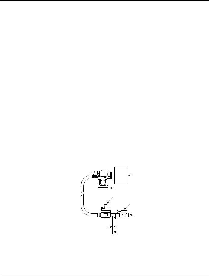
1.Connect the proper size gas pipe at the input to the Natural Gas regulator. Connect the Natural Gas pipe line shown in Figure 3-2 using the correct size pipe for the required flow rate and length of pipe. Refer to Table 3-3 for pipe size. Be certain that all connections are sealed and no leaks are present. The installer must ensure that all gas connections comply with all building codes.
2.Verify Fuel Supply Pressure
Prior to initial operation of generator, verify that fuel system pressure is as indicated in Table 3-2 and fuel pipe sizes comply with Table 3-3.
3.Proceed to Electrical Connections.
Note: Regulator shown for Natural Gas only. For LPG, mount upside down.
Figure 3-2 Gas Line Connections
Carburetor
Air Cleaner
Gasket
Regulator
Solenoid, Fuel Lock
Inlet Connection
Mounting Bracket
3-6 Receiving & Installation |
MN2415 |

Example: Determining Pipe Size for LPG
An AE8 has a 16Hp engine. For LP fuel, determine the supply pipe size for 60 feet run. 16 x 10,000 = 160,000 BTU’s / per hour for proper operation.
160, 000 + 63.5 cubic feet per hour. 2, 516
From Table 3-4, a 60 foot run requires a minimum 1” pipe at full engine load.
LP Gas Connections (vapor withdrawal only)
The LPG connections should only be made if your generator is setup to run on LPG. If it is setup to run on Natural Gas, contact your Baldor representative and do not continue with installation.
The incoming pressure must be as indicated in Table 3-2.
Table 3-4 LP Gas Flow Rate (Cubic Feet per Hour) per Pipe Length
Pipe |
|
|
|
|
|
|
Iron Pipe Size |
|
|
|
|
|
||
Length |
|
|
|
|
|
|
|
|
|
|
|
|
|
|
1/2″ |
3/4″ |
1″ |
1−1/4″ |
1−1/2″ |
|
2″ |
|
2−1/2″ |
3″ |
4″ |
6″ |
8″ |
||
(Feet) |
|
|
||||||||||||
15 |
48 |
109 |
218 |
|
475 |
772 |
|
1570 |
|
2437 |
4115 |
8786 |
24497 |
50007 |
30 |
33 |
76 |
153 |
|
339 |
538 |
|
1127 |
|
1741 |
2975 |
6140 |
17325 |
35353 |
45 |
27 |
63 |
126 |
|
275 |
443 |
|
934 |
|
1456 |
2469 |
5001 |
14781 |
28865 |
60 |
24 |
54 |
110 |
|
241 |
386 |
|
817 |
|
1266 |
2184 |
4304 |
12236 |
25004 |
75 |
|
49 |
98 |
|
218 |
345 |
|
709 |
|
1108 |
1899 |
3798 |
10957 |
22345 |
90 |
|
44 |
89 |
|
196 |
310 |
|
633 |
|
987 |
1709 |
3482 |
10001 |
20414 |
105 |
|
41 |
83 |
|
180 |
285 |
|
582 |
|
905 |
1551 |
3228 |
9254 |
18895 |
120 |
|
|
76 |
|
171 |
266 |
|
544 |
|
848 |
1456 |
3038 |
8659 |
17673 |
150 |
|
|
69 |
|
153 |
241 |
|
494 |
|
772 |
1323 |
2754 |
7748 |
15825 |
180 |
|
|
63 |
|
142 |
222 |
|
456 |
|
709 |
1234 |
2532 |
7064 |
14432 |
210 |
|
|
58 |
|
130 |
202 |
|
418 |
|
652 |
1127 |
2342 |
6439 |
13356 |
240 |
|
|
|
|
120 |
190 |
|
393 |
|
614 |
1063 |
2209 |
6077 |
12405 |
270 |
|
|
|
|
113 |
180 |
|
367 |
|
576 |
1000 |
2057 |
5697 |
11780 |
300 |
|
|
|
|
108 |
171 |
|
345 |
|
544 |
943 |
1899 |
5381 |
11179 |
Note: Almost all operation problems are related to the installation techniques used.
Do Not guess, be sure pipe size is adequate for required flow rate.
1.Connect the proper size gas pipe at the input to the LP Gas regulator. Connect the LPG pipe line shown in Figure 3-2 using the correct size pipe for the required flow rate and length of pipe. Refer to Table 3-4 for pipe size. Be certain that all connections are sealed and no leaks are present. The installer must ensure that all gas connections comply with all building codes.
2.Verify Fuel Supply Pressure
Prior to initial operation of generator, verify that fuel system pressure is as indicated in Table 3-2 and fuel pipe sizes comply with Table 3-4.
3.Proceed to Electrical Connections.
MN2415 |
Receiving & Installation 3-7 |

Electrical Connections Class 1 wiring methods must be used for field wiring connections to terminals of a class 2 circuit. It is the responsibility of the owner/operator to arrange for these procedures to be performed by a licensed electrical contractor and ensure conformance to all applicable codes including local codes peculiar to your municipality/city/county and state. Wire size and insulation type should be as required by NEC (National Electrical Code) and local codes.
Warning: Never connect this generator to the electrical system of any building unless a licensed electrician has installed an approved transfer switch. The national electrical code (NEC) requires that connection of a generator to any electrical circuit normally powered by means of an electric utility must be connected by means of approved transfer switch equipment to isolate the electrical circuit from the utility distribution system when the generator is operating. Failure to isolate the electrical circuits by such means may result in injury or death to utility power workers due to backfeed of electrical energy onto the utility lines.
Warning: Incorrect installation of this generator set could result in property damage, injury or death. Connection of the generator to its fuel source must be done by a qualified professional technician or contractor.
WARNING: Be sure the system is properly grounded before applying power. Do not apply AC power before you ensure that grounds are connected. Electrical shock can cause serious or fatal injury. NEC requires that the frame and exposed conductive surfaces (metal parts) be connected to an approved earth ground. Local codes may also require proper grounding of generator systems.
Intended Use The intended purpose of this generator set is to provide emergency power when the main utility power supply is interrupted. Therefore, it is important that all the wiring that connects the generator set with your house, transfer switch, distribution box, battery charger, etc. be properly installed.
Circuit Protection Circuit protection is not provided with the generator. When connecting the generator output to an electrical load, a UL listed circuit breaker with the appropriate ratings shall be provided within 25 feet of the genset. Use only copper wires.
Generator Rating |
|
Input Breaker |
|
|||
Catalog No. |
Kilowatt (kW) |
1 Phase VAC |
1 Phase |
3 Phase VAC |
3 Phase |
|
Rating |
Amps |
Amps |
||||
|
|
|
||||
|
|
|
|
|
|
|
AE8 |
8 |
120/240 |
|
120/240/480 |
|
|
AE10 |
10 |
120/240 |
|
120/240/480 |
|
|
AE11 |
11 |
120/240 |
|
120/240/480 |
|
|
AE25 |
25 |
120/240 |
|
120/240/480 |
|
|
Transfer Switch Considerations
The following are general considerations for the safe use of a transfer switch:
1.The transfer switch should be located inside the building near the main breaker box or the disconnect box.
2.The transfer switch must be kept away from any location that might allow water to get on it.
3.If the transfer switch is mounted outside, it must be protected from the environment.
4.Do not mount the transfer switch on the generator set.
5.Do not mount the transfer switch where flammable liquids or vapors are present.
Battery Charger Considerations
1.Mount the battery charger on the generator or as close to the generator as possible.
2.If you mount the battery charger inside the building, mount it near the main breaker box or disconnect box.
3.If you mount the battery charger outside, you must protect it from the environment.
4.Do not mount the battery charger where flammable liquids or vapors are present.
3-8 Receiving & Installation |
MN2415 |
General Wiring Considerations
1.Control wires and Power wires cannot be located in the same conduit (NEC Article 725).
2.When routing the interface wiring, do not route it up against anything that could cut or chafe the wiring. do not route the wire up against any hot or potentially hot object.
3.Make sure that all the electrical components (generator set, transfer switch, battery charger, etc.) share a common hardwired ground.
4.Check with your local building inspector to determine what you must do to comply with the local regulations for grounding of this type of permanent installation.
AE8 Electrical Connections Applies only to AE8 Enclosed and Open Series Generators
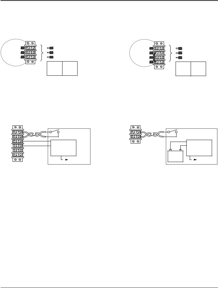
Single Phase Power Connections
The generator has a 240V single phase AC output. These connections are made at the power terminal box shown in Figure 3-3.
Figure 3-3 Single Phase Output Power Connections
AE8 with Enclosure or Open
Generator |
1 |
L1 |
Customer |
L1 to N |
120VAC |
|
N |
N |
|||||
Output |
AC Output Connections |
L2 to N |
120VAC |
|||
4 |
L2 |
(to Transfer Switch) |
L1 to L2 |
240VAC |
||
|
||||||
|
|
|
BW0120D |
|
|
Remote Start and Battery Charger Connections
Figure 3-4 shows the connections for the battery charger and the remote start contacts of the transfer switch. When the Remote Start Switch is closed, the generator will start. The unit will remain running until this connection is opened. When the Remote Start Switch is opened, the control circuits allow the engine to run for approximately 60−90 seconds before it shuts off. This time delay allows the engine to run unloaded to cool down before stopping.
Figure 3-4 Remote Start & Battery Connections
|
AE8 |
|
|
AE8 |
|
|
|
|
with Enclosure |
Customer Provided Optional Equipment |
Open |
|
Customer Provided Optional Equipment |
||||
|
16AWG |
|
16AWG |
|||||
|
|
|
|
|
|
|
||
R1 |
Twisted Pair Wire |
Remote Start Switch |
|
Twisted Pair Wire |
Remote Start Switch |
|||
|
|
|
|
|
||||
R2 |
|
|
(Close to Start) |
|
|
|
(Close to Start) |
|
|
|
|
|
|
|
|
|
|
Batt+ |
|
Out+ |
Battery |
|
|
|
Out+ |
Battery |
Batt− |
|
Out− |
|
|
|
Out− |
||
D1 |
|
|
Charger |
|
|
+ |
− |
Charger |
|
|
|
|
|
|
|||
D2 |
|
|
|
|
|
|
||
|
|
To 120VAC |
BW0183D |
|
Battery |
To 120VAC |
||
|
|
|
|
|||||
|
|
|
(Shore Power) |
|
|
|
|
(Shore Power) |
BW0120D
Note: Connect DK1 and DK2 of the battery charger go to the D1 and D2 terminals of the terminal block if a Master Control Systems Inc. Battery charger is installed. DK1 and DK2 are not polarity sensitive.
MN2415 |
Receiving & Installation 3-9 |
AE10 Electrical Connections Applies only to AE10 Enclosed and Open Series Generators
Single Phase Power Connections
The generator has a 240V single phase AC output. These connections are made at the power terminal box shown in Figure 3-5.
Figure 3-5 Single Phase Output Power Connections
AE10 with Enclosure AE10 Open
Generator |
1 |
L1 |
|
Customer |
|
N |
N |
|
|||
AC Output Connections |
|||||
Output |
|||||
4 |
L2 |
(to Transfer Switch) |
|||
|
|||||
|
|
|
L1 to N |
120VAC |
|
|
|
|
L2 to N |
120VAC |
|
|
|
|
L1 to L2 |
240VAC |
|
BW0333D
BW0201D |
|
|
|
|
|
Generator |
1 |
L1 |
|
Customer |
|
N |
N |
|
|||
AC Output Connections |
|||||
Output |
|||||
4 |
L2 |
(to Transfer Switch) |
|||
|
|||||
To Frame |
G |
|
L1 to N |
120VAC |
|
|
|
|
|||
Note: G and N are internally |
|
L2 to N |
120VAC |
||
|
L1 to L2 |
240VAC |
|||
|
|
|
|||
tied to Frame Ground.
Remote Start and Battery Charger Connections
Figure 3-6 shows the connections for the battery charger and the remote start contacts of the transfer switch. When the Remote Start Switch is closed, the generator will start. The unit will remain running until this connection is opened. When the Remote Start Switch is opened, the control circuits allow the engine to run for approximately 60−90 seconds before it shuts off. This time delay allows the engine to run unloaded to cool down before stopping.
Figure 3-6 Remote Start & Battery Connections
|
AE10 |
|
|
AE10 |
|
|
|
|
with Enclosure |
Customer Provided Optional Equipment |
Open |
|
Customer Provided Optional Equipment |
||||
|
16AWG |
|
16AWG |
|||||
|
|
|
|
|
|
|
||
R1 |
Twisted Pair Wire |
Remote Start Switch |
|
Twisted Pair Wire |
Remote Start Switch |
|||
|
|
|
|
|
||||
R2 |
|
|
(Close to Start) |
|
|
|
(Close to Start) |
|
|
|
|
|
|
|
|
|
|
Batt+ |
|
Out+ |
Battery |
|
|
|
Out+ |
Battery |
Batt− |
|
Out− |
|
|
|
Out− |
||
D1 |
|
|
Charger |
|
|
+ |
− |
Charger |
|
|
|
BW0201D |
|
|
|||
D2 |
|
|
|
|
|
|||
|
|
To 120VAC |
|
|
Battery |
To 120VAC |
||
|
|
|
|
|
||||
|
|
|
(Shore Power) |
|
|
|
|
(Shore Power) |
BW0333D |
Note: Connect DK1 and DK2 of the battery charger go to the D1 and D2 terminals of the terminal block if a Master Control Systems Inc. |
|
|
|
Battery charger is installed. DK1 and DK2 are not polarity sensitive. |
3-10 Receiving & Installation |
MN2415 |
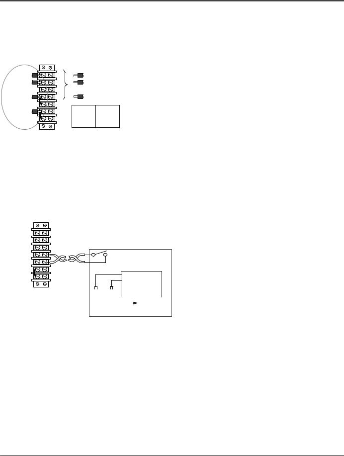
AE11 Electrical Connections Applies only to AE11 Enclosed Series Generators
Single Phase Power Connections
The generator has a 240V single phase AC output. These connections are made at the power terminal box shown in Figure 3-7.
Figure 3-7 Single Phase Output Power Connections
AE11 with Enclosure TBP
|
L1 |
L1 |
|
Customer |
|
L2 |
L2 |
|
|
|
AC Output Connections |
|||
Generator |
L3 |
|
|
(to Transfer Switch) |
Output |
N |
N |
|
|
(Jumpered) |
N |
|
|
|
|
G |
|
L1 to N |
120VAC |
(Jumpered) |
G |
|
L2 to N |
120VAC |
|
L1 to L2 |
240VAC |
||
|
|
|
||
BW0459D
Remote Start and Battery Charger Connections
AE11 with Enclosure
TBP
L1 |
|
|
|
|
|
N |
|
Customer Provided Optional Equipment |
|||
G |
16AWG |
||||
|
|
|
|||
Remote Start |
Twisted Pair Wire |
Remote Start Switch |
|||
|
|
||||
Remote Start |
|
|
(Close to Start) |
||
|
|
|
|
||
Fuel Jumper |
|
|
Out+ |
|
|
Fuel Jumper |
|
|
Battery |
||
|
|
Out− |
|||
|
|
|
|||
|
|
|
Charger |
||
|
|
|
|
||
Fuel Jumper |
+ |
− |
|
|
|
|
|
IN = Natural Gas |
Battery |
|
|
|
|
||
|
|
To 120VAC |
|
||||
OUT = LPG |
|
|
|
|
|
(Shore Power) |
|
|
|
|
|
|
|||
BW0459D
Note: Remove Fuel Jumper
if LP Gas is used.
MN2415 |
Receiving & Installation 3-11 |
 Loading...