

Page 1

AC SERVO DRIVE
Servo Control
Series 29M
Installation
1/98 MN1230
& Operating Manual
Page 2

Table of Contents
Section 1
Receiving & Inspection
Receiving
Section
General Information 2-1.
Introduction 2-1
Limited Warranty 2-2.
Safety
Section
Installation 3-1.
Location
Mechanical
Electrical
AC
Motor
Dynamic
Resolver
Simulated
Control
Analog
External T
Opto-Isolated
Pre-Operation
Power-Up
& Inspection
2
. . . . . . . . . . . . . . . . . . . . . . . . . . . . . . . . . . . . . . . . . . . . . . . . . . . . . . . . . . . . . . . . . . . . . . . . . . . . . . . . . .
Notice
3
. . . . . . . . . . . . . . . . . . . . . . . . . . . . . . . . . . . . . . . . . . . . . . . . . . . . . . . . . . . . . . . . . . . . . . . . . . . . . . . . . . . . . .
Remote
Overload
Power
Protection Devices 3-3.
and DC Power Connections
Connections
Circuit Connections
Active
Keypad
Standard
15
Speed 2-Wire Mode
Fan
Fan
Bipolar
Process
Specific
Inputs and Outputs
Analog
Analog
. . . . . . . . . . . . . . . . . . . . . . . . . . . . . . . . . . . . . . . . . . . . . . . . . . . . . . . . . . . . . . . . . . . . . . . . . . . . . . . .
Considerations
Installation
Keypad Installation
Installation
Protection
Disconnect
Brake Resistor
Feedback
Encoder Output
High/Low Description
Mode
Run 3 Wire Mode
Pump 2 Wire Control Mode
Pump 3 Wire Control Mode
Speed or T
Mode Connections
Process Mode Outputs
Inputs
Outputs
rip Input
Outputs
Checklist
Procedure
. . . . . . . . . . . . . . . . . . . . . . . . . . . . . . . . . . . . . . . . . . . . . . . . . . . . . . . . . . . . . . . . . . . . . . . . . .
. . . . . . . . . . . . . . . . . . . . . . . . . . . . . . . . . . . . . . . . . . . . . . . . . . . . . . . . . . . . . . . . . . . . . . . .
. . . . . . . . . . . . . . . . . . . . . . . . . . . . . . . . . . . . . . . . . . . . . . . . . . . . . . . . . . . . . . . . . . . . . . . . . . . . .
. . . . . . . . . . . . . . . . . . . . . . . . . . . . . . . . . . . . . . . . . . . . . . . . . . . . . . . . . . . . . . . . . . . . . . . . . . . . .
. . . . . . . . . . . . . . . . . . . . . . . . . . . . . . . . . . . . . . . . . . . . . . . . . . . . . . . . . . . . . . . . . . . . . . .
. . . . . . . . . . . . . . . . . . . . . . . . . . . . . . . . . . . . . . . . . . . . . . . . . . . . . . . . . . . . . . . . . . . . . . . .
. . . . . . . . . . . . . . . . . . . . . . . . . . . . . . . . . . . . . . . . . . . . . . . . . . . . . . . . . . . . . . .
. . . . . . . . . . . . . . . . . . . . . . . . . . . . . . . . . . . . . . . . . . . . . . . . . . . . . . . . . . . . . . . . . . . . . . . . . .
. . . . . . . . . . . . . . . . . . . . . . . . . . . . . . . . . . . . . . . . . . . . . . . . . . . . . . . . . . . . . . . . . . . . . .
. . . . . . . . . . . . . . . . . . . . . . . . . . . . . . . . . . . . . . . . . . . . . . . . . . . . . . . . . . . . . . . . . . . . . . . .
. . . . . . . . . . . . . . . . . . . . . . . . . . . . . . . . . . . . . . . . . . . . . . . . . . . . . . . . . . . . . . . . . . . . . . .
. . . . . . . . . . . . . . . . . . . . . . . . . . . . . . . . . . . . . . . . . . . . . . . . . . . . . . . . . . . . . . . .
. . . . . . . . . . . . . . . . . . . . . . . . . . . . . . . . . . . . . . . . . . . . . . . . . . . . . . . . . . . . . . . . . . . . . . . . . . .
. . . . . . . . . . . . . . . . . . . . . . . . . . . . . . . . . . . . . . . . . . . . . . . . . . . . . . . . . . . . . . . . . . . . . . .
. . . . . . . . . . . . . . . . . . . . . . . . . . . . . . . . . . . . . . . . . . . . . . . . . . . . . . . . . . . . . . . . . . . . . . . . . . .
. . . . . . . . . . . . . . . . . . . . . . . . . . . . . . . . . . . . . . . . . . . . . . . . . . . . . . . . . . . . . . . . . . . . .
. . . . . . . . . . . . . . . . . . . . . . . . . . . . . . . . . . . . . . . . . . . . . . . . . . . . . . . . . . . . . . . . . . . .
. . . . . . . . . . . . . . . . . . . . . . . . . . . . . . . . . . . . . . . . . . . . . . . . . . . . . . . . . . . . . . .
. . . . . . . . . . . . . . . . . . . . . . . . . . . . . . . . . . . . . . . . . . . . . . . . . . . . . . . . . . . . . . . . . . . . . . . . . . .
. . . . . . . . . . . . . . . . . . . . . . . . . . . . . . . . . . . . . . . . . . . . . . . . . . . . . . . . . . . . . . . .
. . . . . . . . . . . . . . . . . . . . . . . . . . . . . . . . . . . . . . . . . . . . . . . . . . . . . . . . . . . . . . . . . . .
. . . . . . . . . . . . . . . . . . . . . . . . . . . . . . . . . . . . . . . . . . . . . . . . . . . . . . . . . . . .
. . . . . . . . . . . . . . . . . . . . . . . . . . . . . . . . . . . . . . . . . . . . . . . . . . . . . . . . . . . .
orque Control Mode with Multiple Parameter Sets
. . . . . . . . . . . . . . . . . . . . . . . . . . . . . . . . . . . . . . . . . . . . . . . . . . . . . . . . . . . . . . .
. . . . . . . . . . . . . . . . . . . . . . . . . . . . . . . . . . . . . . . . . . . . . . . . . . . . . . . . . . . .
. . . . . . . . . . . . . . . . . . . . . . . . . . . . . . . . . . . . . . . . . . . . . . . . . . . . . . . . . . . . . . . . . . . .
. . . . . . . . . . . . . . . . . . . . . . . . . . . . . . . . . . . . . . . . . . . . . . . . . . . . . . . . . . . . . . . . . . . . . . . . . . .
. . . . . . . . . . . . . . . . . . . . . . . . . . . . . . . . . . . . . . . . . . . . . . . . . . . . . . . . . . . . . . . . . . . . . . . . . .
. . . . . . . . . . . . . . . . . . . . . . . . . . . . . . . . . . . . . . . . . . . . . . . . . . . . . . . . . . . . . . . . . . . . . . . . . . . .
. . . . . . . . . . . . . . . . . . . . . . . . . . . . . . . . . . . . . . . . . . . . . . . . . . . . . . . . . . . . . . . . . . . . . . . .
. . . . . . . . . . . . . . . . . . . . . . . . . . . . . . . . . . . . . . . . . . . . . . . . . . . . . . . . . . . . . . . . . . . . . . .
. . . . . . . . . . . . . . . . . . . . . . . . . . . . . . . . . . . . . . . . . . . . . . . . . . . . . . . . . . . . . . . . . . . . . . . . .
. . . . . . . . . . . . . . . . . . . . . . . . . . . .
1-1.
1-1.
2-3.
3-1.
3-1.
3-2.
3-3.
3-3.
3-3.
3-6.
3-6.
3-6.
3-8.
3-9.
3-10.
3-11.
3-12.
3-14.
3-16.
3-18.
3-20.
3-22.
3-24.
3-26.
3-28.
3-28.
3-30.
3-30.
3-31.
3-32.
3-33.
MN1230
Table
of Contents i
Page 3

Section 1
General Information
Section 4
Programming and Operation 4-1.
Overview 4-1
Display
Program
Parameter
Section
Troubleshooting 5-1.
Section
Manually T
5
Overview 5-1
Control T
How
Electrical
Wiring Practices 5-17.
Optical
Plant
6
Manually T
. . . . . . . . . . . . . . . . . . . . . . . . . . . . . . . . . . . . . . . . . . . . . . . . . . . . . . . . . . . . . . . . . . . . . . . . . . . . . . . . . . . .
Mode
Adjusting
Display
Fault Log Access 4-4.
Parameter
Changing
Reset
Initialize
No
Keypad Display - Display Contrast Adjustment
How
to Clear the Fault Log
How
Causes
Special
Drive
Radio Transmitters 5-15.
Control
Special
Isolation
Ground
uning the Series 29M Control
Definition
Definition
Definition
Definition
Definition
Current
Current
Speed
Speed
. . . . . . . . . . . . . . . . . . . . . . . . . . . . . . . . . . . . . . . . . . . . . . . . . . . . . . . . . . . . . . . . . . . . . . . . . . . . . . . .
Display Contrast
Screens & Diagnostic Information Access
Mode
roubleshooting Procedure
to Access the Fault Log
to Access Diagnostic Information
Noise Considerations
. . . . . . . . . . . . . . . . . . . . . . . . . . . . . . . . . . . . . . . . . . . . . . . . . . . . . . . . . . . . . . . . . . . . . . . . . . . . . . .
Blocks Access for Programming
Parameter V
Parameters to Factory Settings
New Software EEPROMs
Adjustments
. . . . . . . . . . . . . . . . . . . . . . . . . . . . . . . . . . . . . . . . . . . . . . . . . . . . . . . . . . . . . . . . . . . . . . . . . . . . . . . .
. . . . . . . . . . . . . . . . . . . . . . . . . . . . . . . . . . . . . . . . . . . . . . . . . . . . . . . . . . . . . . . . . . . . . . . . . . . . . . . . . . . .
and Cures
Drive Situations
Power Lines
Enclosures
Motor Considerations
. . . . . . . . . . . . . . . . . . . . . . . . . . . . . . . . . . . . . . . . . . . . . . . . . . . . . . . . . . . . . . . . . . . . . . . . . . . . .
. . . . . . . . . . . . . . . . . . . . . . . . . . . . . . . . . . . . . . . . . . . . . . . . . . . . . . . . . . . . . . . . . . . . . . . . . . . . . .
. . . . . . . . . . . . . . . . . . . . . . . . . . . . . . . . . . . . . . . . . . . . . . . . . . . . . . . . . . . . . . . . . . . . . . . . . . . . . . . .
of Input Command
of Feedback
of Error
of “P” (Proportional gain)
of “I” (Integral gain)
uning the Control
Prop Gain Parameter
Int Gain Parameter
Prop Gain Parameter
Int Gain Parameter
. . . . . . . . . . . . . . . . . . . . . . . . . . . . . . . . . . . . . . . . . . . . . . . . . . . . . . . . . . . . . . . . . . . . .
. . . . . . . . . . . . . . . . . . . . . . . . . . . . . . . . . . . . . . . . . . . . . . . . . . . . . . . . . . . . . . . .
. . . . . . . . . . . . . . . . . . . . . . . . . . . . . . . . . . . . . . . . . . . .
. . . . . . . . . . . . . . . . . . . . . . . . . . . . . . . . . . . . . . . . . . . . . . . . . . . . . . . . . . . . . . . . . . . . . . . .
. . . . . . . . . . . . . . . . . . . . . . . . . . . . . . . . . . . . . . . . . . . . . . . . . .
alues when Security Code Not Used
. . . . . . . . . . . . . . . . . . . . . . . . . . . . . . . . . . . . . . . . . . . . . . . . . . . . . .
. . . . . . . . . . . . . . . . . . . . . . . . . . . . . . . . . . . . . . . . . . . . . . . . . . . . . . . . .
. . . . . . . . . . . . . . . . . . . . . . . . . . . . . . . . . . . . . . . . . . . . . . . . . . . . . . . . . . . . . . . . . . . . . . .
. . . . . . . . . . . . . . . . . . . . . . . . . . . . . . . . . . . . . . . . . . . . . . . . . . . . . . . . . . . . .
. . . . . . . . . . . . . . . . . . . . . . . . . . . . . . . . . . . . . . . . . . . .
. . . . . . . . . . . . . . . . . . . . . . . . . . . . . . . . . . . . . . . . . . . . . . . . . . . . . . . . . . . . . .
. . . . . . . . . . . . . . . . . . . . . . . . . . . . . . . . . . . . . . . . . . . . . . . . . . . . . . . . . . . . . . . . . . . .
. . . . . . . . . . . . . . . . . . . . . . . . . . . . . . . . . . . . . . . . . . . . . . . . . . . . . .
. . . . . . . . . . . . . . . . . . . . . . . . . . . . . . . . . . . . . . . . . . . . . . . . . . . . . . . . . . . . . . . .
. . . . . . . . . . . . . . . . . . . . . . . . . . . . . . . . . . . . . . . . . . . . . . . . . . . . . . . . . . . . . . . . . . . . . . .
. . . . . . . . . . . . . . . . . . . . . . . . . . . . . . . . . . . . . . . . . . . . . . . . . . . . . . . . . . . . . . . . . . .
. . . . . . . . . . . . . . . . . . . . . . . . . . . . . . . . . . . . . . . . . . . . . . . . . . . . . . . . . . . . . . . . . . . . . . .
. . . . . . . . . . . . . . . . . . . . . . . . . . . . . . . . . . . . . . . . . . . . . . . . . . . . . . . . . . . . . . . . . . . . . . .
. . . . . . . . . . . . . . . . . . . . . . . . . . . . . . . . . . . . . . . . . . . . . . . . . . . . . . . . . . . . . . . . . . . . . . .
. . . . . . . . . . . . . . . . . . . . . . . . . . . . . . . . . . . . . . . . . . . . . . . . . . . . . . . . . . . . . .
. . . . . . . . . . . . . . . . . . . . . . . . . . . . . . . . . . . . . . . . . . . . . . . . . . . . . . . . . . .
. . . . . . . . . . . . . . . . . . . . . . . . . . . . . . . . . . . . . . . . . . . . . . . . . . . . . . . . . . . . . .
. . . . . . . . . . . . . . . . . . . . . . . . . . . . . . . . . . . . . . . . . . . . . . . . . . . . . . . . . . . . . . . . . . . .
. . . . . . . . . . . . . . . . . . . . . . . . . . . . . . . . . . . . . . . . . . . . . . . . . . . . . . . . . . . . . . . . . . . . . . . .
. . . . . . . . . . . . . . . . . . . . . . . . . . . . . . . . . . . . . . . . . . . . . . . . . . . . . . . . .
. . . . . . . . . . . . . . . . . . . . . . . . . . . . . . . . . . . . . . . . . . . . . . . . . . . . . . . . . . . . . .
. . . . . . . . . . . . . . . . . . . . . . . . . . . . . . . . . . . . . . . . . . . . . . . . . . . . . . . . . . . . . . . . . . .
. . . . . . . . . . . . . . . . . . . . . . . . . . . . . . . . . . . . . . . . . . . . . . . . . . . . . . . . . . . . . .
. . . . . . . . . . . . . . . . . . . . . . . . . . . . . . . . . . . . . . . . . . . . . . . . . . . . . . . . . . . . . . . .
. . . . . . . . . . . . . . . . . . . . . . . . . . . . . . . . . . . . . . . . . . . . . . . . . . . . . . . . . . . . . . .
. . . . . . . . . . . . . . . . . . . . . . . . . . . . . . . . . . . . . . . . . . . . . . . . . . . . . . . . . . . . . . . . .
. . . . . . . . . . . . . . . . . . . . . . . . . . . . . . . . . . .
4-2.
4-2.
4-3.
4-5.
4-5.
4-6.
4-7.
4-8.
4-9.
5-2.
5-2.
5-4.
5-4.
5-5.
5-12.
5-12.
5-15.
5-15.
5-16.
5-16.
5-18.
5-18.
6-1.
6-1.
6-1.
6-1.
6-2.
6-3.
6-5.
6-5.
6-6.
6-6.
6-6.
ii T
able of Contents
MN1230
Page 4

Section 1
General Information
Section 7
Specifications and Product Data
Identification 7-1
Servo
Control Specifications:
Keypad
Differential
Analog
Digital
Inputs:
Digital
Outputs:
Diagnostic
DB
Resistor Selection
Terminal T
Dimensions 7-7
Mounting
Appendix
Appendix
A
Parameter Values A-1.
B
Remote
. . . . . . . . . . . . . . . . . . . . . . . . . . . . . . . . . . . . . . . . . . . . . . . . . . . . . . . . . . . . . . . . . . . . . . . . . . . . . . . . . .
Display:
Analog Input:
Outputs:
Indications:
ightening T
Hole Location
. . . . . . . . . . . . . . . . . . . . . . . . . . . . . . . . . . . . . . . . . . . . . . . . . . . . . . . . . . . . . . . . . . . . . . . . . . . . . . . . . . . . .
. . . . . . . . . . . . . . . . . . . . . . . . . . . . . . . . . . . . . . . . . . . . . . . . . . . . . . . . . . . . . . . . . . . . . . . . . . . . . . . . . . . . .
Keypad Mounting T
. . . . . . . . . . . . . . . . . . . . . . . . . . . . . . . . . . . . . . . . . . . . . . . . . . . . . . . . . . . . . . . . . . . . . . . . . . . . .
. . . . . . . . . . . . . . . . . . . . . . . . . . . . . . . . . . . . . . . . . . . . . . . . . . . . . . . . . . . . . . . . . . . . . . . . . . . . . .
. . . . . . . . . . . . . . . . . . . . . . . . . . . . . . . . . . . . . . . . . . . . . . . . . . . . . . . . . . . . . . . . . . . . . . . . . . . . . . . .
. . . . . . . . . . . . . . . . . . . . . . . . . . . . . . . . . . . . . . . . . . . . . . . . . . . . . . . . . . . . . . . . . . . . . . . . . . . . . .
. . . . . . . . . . . . . . . . . . . . . . . . . . . . . . . . . . . . . . . . . . . . . . . . . . . . . . . . . . . . . . . . . . . . . . . .
. . . . . . . . . . . . . . . . . . . . . . . . . . . . . . . . . . . . . . . . . . . . . . . . . . . . . . . . . . . . . . . . . . . . . . . . .
orque Specifications
. . . . . . . . . . . . . . . . . . . . . . . . . . . . . . . . . . . . . . . . . . . . . . . . . . . . . . . . . . . . . . . . . . . . . . . . . . . . . . . . . .
. . . . . . . . . . . . . . . . . . . . . . . . . . . . . . . . . . . . . . . . . . . . . . . . . . . . . . . . . . . . . . . . . . . . . . . . . . . .
. . . . . . . . . . . . . . . . . . . . . . . . . . . . . . . . . . . . . . . . . . . . . . . . . . . . . . . . . . . . . . . . . .
. . . . . . . . . . . . . . . . . . . . . . . . . . . . . . . . . . . . . . . . . . . . . . . . . . . . . . . . . . . . . . . . . .
. . . . . . . . . . . . . . . . . . . . . . . . . . . . . . . . . . . . . . . . . . . . . . . . . . . . . . . . . . . . . . . . . . . . . .
. . . . . . . . . . . . . . . . . . . . . . . . . . . . . . . . . . . . . . . . . . . . . . . . . . . . . . .
. . . . . . . . . . . . . . . . . . . . . . . . . . . . . . . . . . . . . . . . . . . . . . . . . . . . . . . . . . . . . . . . . . . . . . .
emplate B-2.
. . . . . . . . . . . . . . . . . . . . . . . . . . . . . . . . . . . . . . . . . . . . . . . . . . . . . . . . . . . .
7-1.
7-2.
7-3.
7-3.
7-4.
7-4.
7-4.
7-4.
7-5.
7-6.
7-8.
A-1.
B-1.
MN1230
Table
of Contents iii
Page 5

Section 1
General Information
iv T
able of Contents
MN1230
Page 6

Section 1
Receiving & Inspection
Receiving & Inspection Baldor
When you receive your control, there are several things you should do immediately
Controls are thoroughly tested at the factory and carefully packaged for shipment.
.
1.
Observe the condition of the shipping container and report any damage
immediately to the commercial carrier that delivered your control.
2.
Remove the Control from the shipping container and remove all packing
materials. The container and packing materials may be retained for future
shipment.
3. V
erify that the part number of the control you received is the same as the part
number listed on your purchase order
4.
Inspect the control for external physical damage that may have been sustained
during shipment and report any damage immediately to the commercial carrier
that delivered your control.
5.
If the control is to be stored for several weeks before use, be sure that it is
stored in a location that conforms to published storage humidity and
temperature specifications. (Refer to Section 7 of this manual).
.
MN1230
Receiving
& Inspection 1-1
Page 7

Section 1
General Information
1-2
Receiving & Inspection
MN1230
Page 8
Section 2
General Information
Introduction
Baldor Controls represent the latest technology in microprocessor based motor controls.
The Series 29M control adjusts current to produce maximum torque (to zero speed).
This provides instantaneous adjustment in response to the speed and position feedback
from a shaft mounted resolver
A keypad interface is used to program the Series 29M parameters to customize your
application. The keypad is used to program the control parameters, set the mode of
operation, monitor the Local mode operation status, perform diagnostics, and examine
fault log.
Baldor has tried to ensure that the information in this manual is correct at the time of
printing. The information is subject to change without prior notice.
.
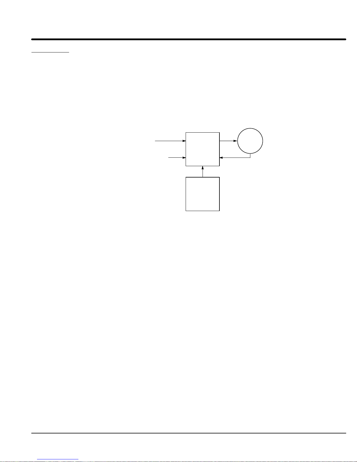
Figure 2-1 29M Control and Motor
AC Power
29M
Motor
Control
Speed
Command
DB
Assembly
Feedback
MN1230
General
Information 2-1
Page 9

Limited Warranty
For a period of one (1) year from the date of original purchase, BALDOR will
repair or replace without charge controls which our
be
defective
in material or workmanship. This warranty is valid if the unit has
not been tampered with by unauthorized persons, misused, abused, or
improperly
installed and has been used in accordance
and/or ratings supplied. This warranty is in lieu of any other warranty or
guarantee
expressed or implied. BALDOR shall not be held responsible for
any expense (including installation and removal), inconvenience, or
consequential
damage, including injury to any person or property caused by
items of our manufacture or sale. (Some states do not allow exclusion or
limitation of incidental or consequential damages, so the above exclusion
may
not
apply
.) In any event, Baldor’s total liability
shall
not exceed the full purchase price of the
price
refunds, repairs, or replacements must be referred to BALDOR with all
pertinent
data as to the defect, the date purchased, the task performed
the control, and the problem encountered. No liability is assumed for
expendable
items such as fuses.
Goods may be returned only with written notification including a BALDOR
Return
Authorization Number and any return shipments must be prepaid.
examination proves to
with the instructions
, under all circumstances,
control. Claims for purchase
by
2-2
General Information
MN1230
Page 10

Safety Notice: This
Only qualified personnel should attempt the start–up procedure or troubleshoot this
equipment.
This equipment may be connected to other machines that have rotating parts or parts
that are driven by this equipment. Improper use can cause serious or fatal injury
qualified personnel should attempt the start–up procedure or troubleshoot this equipment.
PRECAUTIONS:
equipment contains high voltages. Electrical shock can cause serious or fatal injury
. Only
W
ARNING:
Do not touch any circuit board, power device or electrical
connection before you first ensure that power has been
disconnected and there is no high voltage present from this
equipment or other equipment to which it is connected. Electrical
shock can cause serious or fatal injury
. Only qualified personnel
should attempt the start–up procedure or troubleshoot this
equipment.
W
ARNING:
Be sure that you are completely familiar with the safe operation of
this equipment. This equipment may be connected to other
machines that have rotating parts or parts that are controlled by
this equipment. Improper use can cause serious or fatal injury
.
Only qualified personnel should attempt the start–up procedure or
troubleshoot this equipment.
W
ARNING: Do not attempt to service this equipment while bus voltage is
present within the control. Remove input power and wait at least 5
minutes for the residual voltage in the bus capacitors to dissipate.
.
W
ARNING:
Be sure all wiring complies with the National Electrical Code and all
regional and local codes. Improper wiring may result in unsafe
conditions.
W
ARNING:
Be sure the system is properly grounded before applying power
Do not apply AC power before you ensure that grounds are
connected. Electrical shock can cause serious or fatal injury
W
ARNING:
Do not remove cover for at least five (5) minutes after AC power is
disconnected to allow capacitors to discharge. Electrical shock can
cause serious or fatal injury
W
ARNING: Improper operation of control may cause violent motion of the
.
motor shaft and driven equipment. Be certain that unexpected
motor shaft movement will not cause injury to personnel or damage
to equipment. Peak torque of several times the rated motor torque
can occur during control failure.
W
ARNING:
Motor circuit may have high voltage present whenever AC power is
applied, even when motor is not rotating. Electrical shock can
cause serious or fatal injury
W
ARNING: The motor shaft will rotate during the autotune procedure. Be
.
certain that unexpected motor shaft movement will not cause injury
to personnel or damage to equipment.
W
ARNING:
A DB Resistor may generate enough heat to ignite combustible
materials. T
o avoid fire hazard, keep all combustible materials and
flammable vapors away from brake resistors.
.
.
Continued on next page.
MN1230
General Information 2-3
Page 11

Section 1
General Information
Caution: T
Caution: To prevent equipment damage, be certain that the input power has
CAUTION: A
CAUTION: A
Caution: Do not connect any shields to the motor frame. At a minimum,
o prevent equipment damage, be certain that the electrical service
is not capable of delivering more than the maximum line short
circuit current amperes listed for 1
correctly sized protective devices installed as well as a power
disconnect.
void locating control immediately above or beside heat generating
equipment, or directly below water or steam pipes.
void locating control in the vicinity of corrosive substances or
vapors, metal particles and dust.
resolver signal integrity will be compromised and damage to the
control may result.
15 V
AC or 230 V
AC control rating.
2-4
General Information
MN1230
Page 12

Section 3
Installation
Location Considerations The
from direct sunlight, corrosives, harmful gases or liquids, dust, metallic particles, and
vibration. Exposure to these can reduce the operating life and degrade performance of
the control.
Several other factors should be carefully evaluated when selecting a location for
installation:
location of the control is important. It should be installed in an area that is protected
CAUTION: A
CAUTION: A
1.
For ef
smooth, non-flammable vertical surface. The amount of heat generated within
the control can be calculated based on T
2.
At least two inches top and bottom clearance must be provided for air flow
3. Altitude derating
3300 feet, derate the continuous and peak output current by 1
feet (1000 meters) above 3300 feet.
4. T
Maximum ambient is 40°C.
void locating control immediately above or beside heat generating
equipment, or directly below water or steam pipes.
void locating control in the vicinity of corrosive substances or
vapors, metal particles and dust.
fective cooling and maintenance, the control should be mounted on a
able 3-1.
. Up to 3300 feet (1000 meters) no derating required. Above
1% for each 3300
emperature derating
. From 5°C to 40°C ambient no derating required.
.
Table 3-1 Control Efficiency
Mechanical Installation Mount
mounting surface. Use the two (2) mounting holes to fasten the control to the mounting
surface or enclosure. The location of the mounting holes are shown in Section 7 of this
manual.
115 VAC / 230 V
>97%
the control to the mounting surface. The control must be securely fastened to the
AC
MN1230
Installation
3-1
Page 13

Section 1
General Information
Remote Keypad Installation
Mounting Instructions: For tapped mounting holes
Mounting Instructions:
The keypad may be remotely mounted using the optional Baldor keypad extension
cable. The keypad assembly (grey - DC00005A-02) comes complete with the screws
and gasket required to mount it to an enclosure. When the keypad is properly mounted
to a NEMA T
Tools Required:
•
•
• 1-1/4″
• R
•
•
•
1.
2.
3.
4.
5.
6.
7.
8.
9.
For clearance mounting holes
1.
2.
3.
4.
5.
6.
7.
8.
9.
ype 4 indoor enclosure, it retains the T
Center punch, tap handle, screwdrivers (Phillips and straight) and crescent
wrench.
8-32 tap and #29 drill bit (for tapped mounting holes) or #19 drill (for clearance
mounting holes).
standard knockout punch (1-11/16″
TV sealant.
(4) 8-32 nuts and lock washers.
Extended 8-32 screws (socket fillister) are required if the mounting surface is
thicker than 12 gauge and is not tapped (clearance mounting holes).
Remote keypad mounting template. A tear out copy is provided at the end of
this manual for your convenience.
Locate a flat 4″ wide x 5.5″ minimum high mounting surface. Material should
be suf
ficient thickness (14 gauge minimum).
Place the template on the mounting surface or mark the holes as shown.
Accurately center punch the 4 mounting holes (marked A) and the large
knockout (marked B).
Drill four #29 mounting holes (A). Thread each hole using an 8-32 tap.
Locate the 1-1/4″
instructions.
Debur knockout and mounting holes making sure the panel stays clean and flat.
Apply R
Assemble the keypad to the panel. Use 8–32 screws, nuts and lock washers.
From the inside of the panel, apply R
and nuts. Cover a 3/4″
encapsulate the nut and washer
Locate a flat 4″ wide x 5.5″ minimum high mounting surface. Material should
be suf
Place the template on the mounting surface or mark the holes as shown on the
template.
Accurately center punch the 4 mounting holes (marked A) and the large
knockout (marked B).
Drill four #19 clearance holes (A).
Locate the 1-1/4″
instructions.
Debur knockout and mounting holes making sure the panel stays clean and flat.
Apply R
Assemble the keypad to the panel. Use 8–32 screws, nuts and lock washers.
From the inside of the panel, apply R
and nuts. Cover a 3/4″
encapsulate the nut and washer
TV to the 4 holes marked (A).
ficient thickness (14 gauge minimum).
TV to the 4 holes marked (A).
knockout center (B) and punch using the manufacturers
knockout center (B) and punch using the manufacturers
ype 4 indoor rating.
nominal diameter).
TV over each of the four mounting screws
area around each screw while making sure to completely
.
TV over each of the four mounting screws
area around each screw while making sure to completely
.
3-2
Installation
MN1230
Page 14

Section 1
I
Wi
Maximum
Input
General Information
Electrical Installation All
wiring. The use of shielded wire is recommended for all control wiring.
When interconnecting wires from power source, control, motor
devices it is important to make proper electrical connections. A connection must ensure
that proper electrical connection and mechanical bond of conductors. Use only UL (cUL)
listed connectors for the wire gauge and type being connected. Connectors are to be
installed using the crimp tool specified by the connector manufacturer
wiring.
Overload Protection Baldor
least 50% of the output rating of the control. Other governing agencies such as NEC
(National Electric Code) may require separate over current protection. The installer of this
equipment is responsible for complying with NEC guidelines and CE directives
(Conformite Europeene) and applicable local codes that govern wiring protection,
grounding, disconnects and other current protection.
Power Disconnect A
for a fail safe method to disconnect power
condition until all input power is removed from the control and the internal bus voltage is
depleted.
Protection Devices The
output wire size is based on the use of copper conductor wire rated at 75 °C. Use the
recommended circuit breaker or fuse types as follows:
T
protection devices.
external wires for the control should be run in conduit that is separate from power
, host controller and other
. Wire with Class 1
Controls feature motor overload protection suitable for motors that consume at
power disconnect should be installed between the input power service and the control
. The control will remain in a powered-up
control must have a suitable input power protection device installed. Input and
Circuit Breaker:
Fast Action Fuses:
T
ime Delay Fuses:
1 phase, thermal magnetic.
Equal to GE type THQ or TEB for 1
Buss KTN on 1
15 or 230 V
AC.
Buss
Buss FRN on 1
15 or 230 V
AC.
15 or 230 V
AC
able 3-2 describes the wire size to be used for power connections and the ratings of the
Table 3-2 Wire Size and Protection Devices
Fast
Acting
nput Fuse
Time Delay AWG mm
Input
Catalog Number
SD29M1A02-PR 2.5 18 4 4 #14 2.5
SD29M1A05-PR 5 35 8 8 #14 2.5
SD29M2A02-PR 2.5 18 4 4 #14 2.5
SD29M2A05-PR 5 35 8 8 #14 2.5
Note: All
wire sizes based on 75°C copper wire, 3% line impedance. Higher temperature smaller gauge wire may be
Maximum
Continuous
Amps
Breaker
re Gauge
used per NEC and local codes. Recommended fuses/breakers are based on 25°C ambient, maximum
continuous control output current and no harmonic current.
2
MN1230
Installation
3-3
Page 15

Section 1
General Information
Table 3-3 Short Circuit Current Ratings
115VAC 230VAC
Catalog Numbers Max. Line
Short Circuit
Current
SD29M1A02-PR 150 SD29M2A02-PR 150
SD29M1A05-PR 300 SD29M2A05-PR 300
Catalog Numbers Max. Line
Short Circuit
Current
Table 3-4 Input Current Requirements
230VAC 460VAC
Catalog Numbers Input
Amps
SD29M1A02-PR 2.6 SD29M2A02-PR 2.6
SD29M1A05-PR 5.2 SD29M2A05-PR 5.2
Catalog Numbers Input
Amps
3-4
Installation
MN1230
Page 16

Section 1
General Information
Figure 3-1 Single Phase AC Power and Motor Connections
L1 L2
Note 1
Note 2
* Circuit
Breaker
LN PE
Baldor
Control
Earth
Alternate *
Fuse
Connection
L1 L2
Note 1
UVW
PE
Note 2
VW
U
G
* Motor
Notes:
1. See Protective Device description in this section of the manual.
2. Shield wires inside a metal conduit.
* Optional components not provided with Control.
Optional Connection of
UVW
M* M* M*
PE
To Power Source
(Rated Coil
Voltage)
M-Contactor
* M-Contactor
* Optional
RC Device
Electrocube
RG1781-3
VW
U
G
* Motor
MN1230
J1
*
M Enable
7
8
9
Note: Close “Enable”
after “M” contact closure.
See Recommended Tightening Torques in Section 7.
Installation
3-5
Page 17
Section 1
General Information
AC and DC Power ConnectionsRefer
W
ARNING:
1.
2.
Motor Connections A
Dynamic Brake Resistor
motor circuit contactor (M-Contactor shown in Figure 3-1) is recommended and should
be installed to provide a positive disconnect of the motor from the control. This ensures
that the motor shaft will not rotate and cause damage or injury
open the Enable line (J1B pin 8) 20 msec before the main M-Contacts open. This will
prevent contact arcing and allows use of IEC rated contacts.
1.
2.
3.
4.
An external DB (Dynamic Brake) resistor must be installed to dissipate excess power
from the DC bus during motor deceleration operations.
W
ARNING:
to Figures 3-1 and 3-3.
Do not touch any circuit board, power device or electrical
connection before you first ensure that power has been
disconnected and there is no high voltage present from this
equipment or other equipment to which it is connected. Electrical
shock can cause serious or fatal injury
.
Connect the single phase incoming power wires from the protection devices to
the control terminal X1 pins L and N. T
orque as specified.
Connect earth ground (plant ground) to control terminal X1 pin PE.
T
orque as specified.
. The M-contactor should
Connect the “U” terminal of the 29M to the U motor lead.
Connect the “V” terminal of the 29M to the V motor lead.
Connect the “W” terminal of the 29M to the W motor lead.
Connect the “PE” terminal of the 29M to motor ground (G).
A DB Resistor may generate enough heat to ignite combustible
materials. T
o avoid fire hazard, keep all combustible materials and
flammable vapors away from brake resistors.
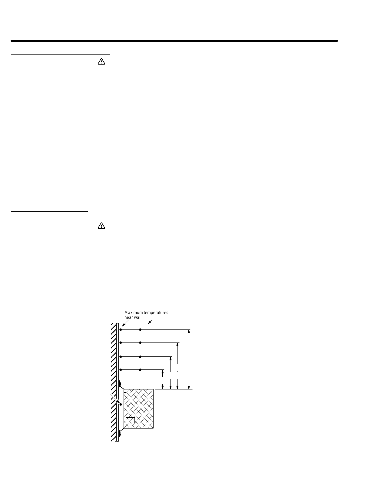
1.
Mount the DB resistor near the top of the enclosure.
2.
Connect one wire from the DB resistor to terminal DB+ of the control.
3.
Connect the other wire from the DB resistor to terminal DB– of the control.
Note:
For selection of the DB resistor
, refer to the Specifications located in Section 7
of this manual.
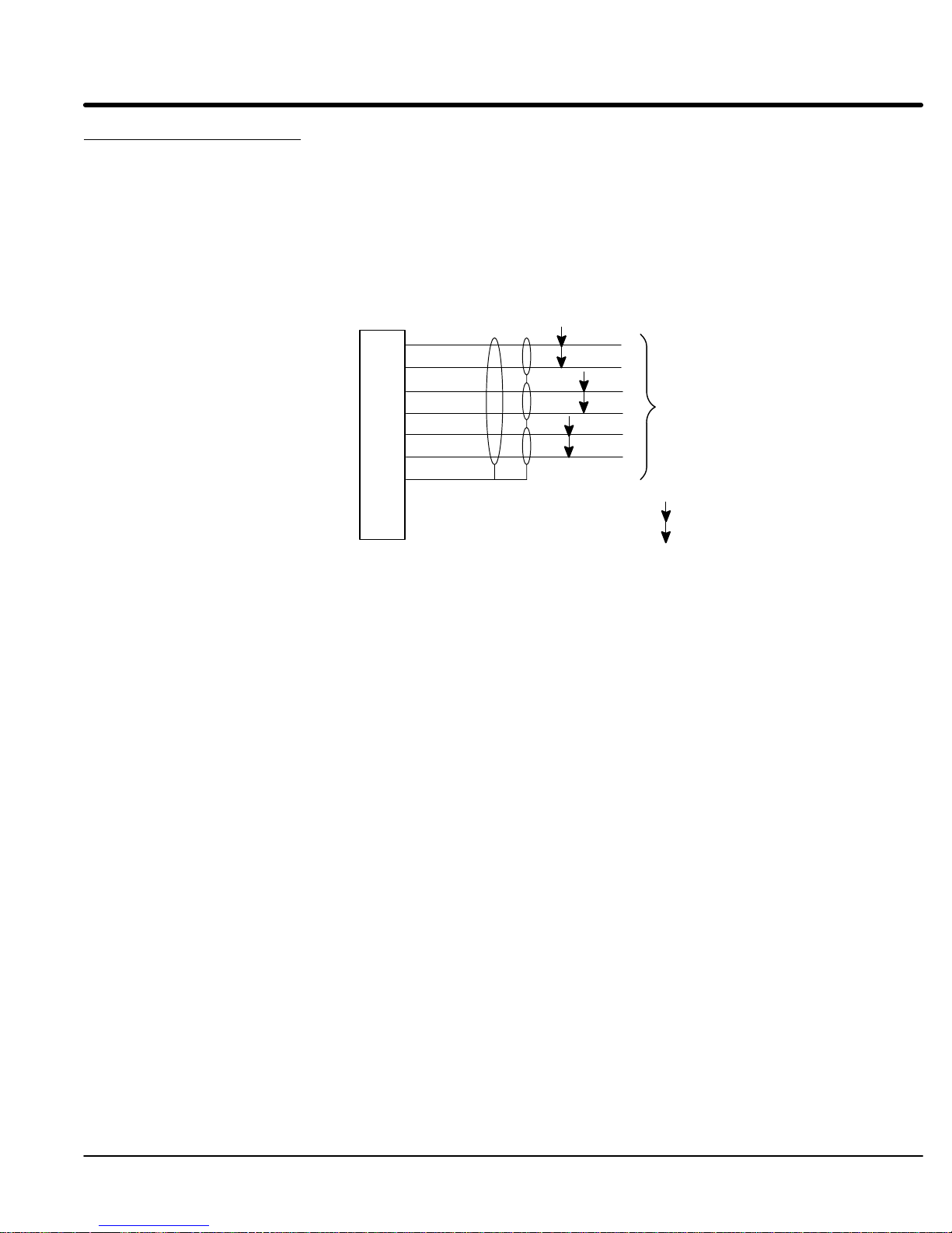
Figure 3-2 DB Resistor Installation Considerations
75°C
Maximum
near wall.
80°C
70°C
65°C
70°C
temperatures
Maximum temperatures
above the enclosure.
85°C
115°C
115°C
200°C
24″
12″
48″
36″
3-6
Installation
MN1230
Page 18
Section 1
General Information
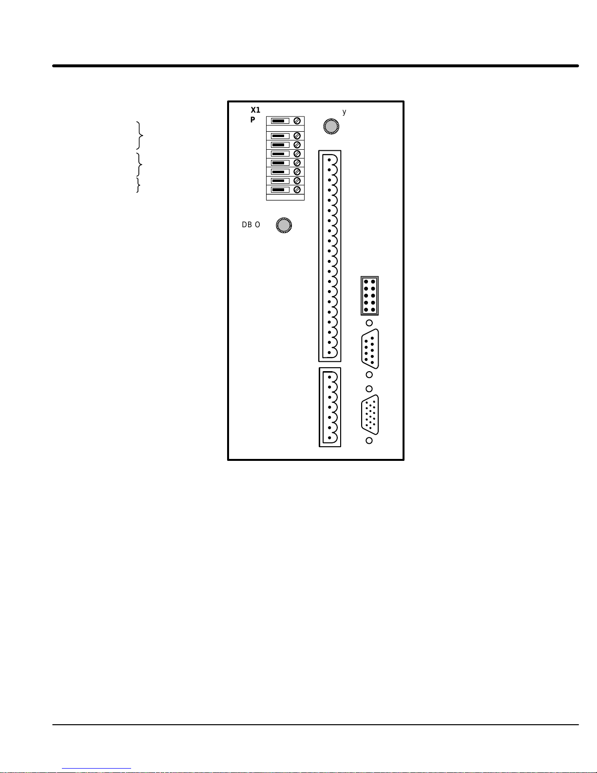
Figure 3-3 29M AC Servo Connector Locations
X1 - Power Connector
PE Earth
L AC Line
N Neutral
U Motor lead “U”
V Motor lead “V”
W Motor lead “W”
DB+ Dynamic Brake
DB– Dynamic Brake
8 Enable 18 N.C.
9 FWD CMD 19 CREF (OPTO IN)
10 REV CMD 20 OUT1–
11 IN1 21 OUT1+
12 IN2 22 OUT2–
13 IN3 23 OUT2+
14 IN4 24 OUT3–
15 IN5 25 OUT3+
16 External Trip 26 OUT4–
17 N.C. 27 OUT4+
J1A - Analog I/O
1 AGND 5 ANA IN 2–
2 ANA IN 1 6 ANA OUT1
3 Reference 7 ANA OUT2
4 ANA IN 2+
See T
erminal T
Input Power
Motor
Dynamic
Regen Resistor
J1B - Digital I/O
ightening T
Section 7 of this manual.
Brake or
orques in
X1
PE
L
N
U
V
W
DB+
DB–
DB ON
BALDOR
J1A
8
1
Ready
J1B
J2
J4
J3
J4 - Keypad
1 Shield 6 RCV–
2 N.C. 7 N.C.
3 XMIT+ 8 N.C.
4 XMIT– 9 +8VDC
5 RCV+ 10 DGND
J3 - Simulated Encoder Output
1 CHA+ 6 CHA–
2 CHB+ 7 CHB–
3 CHC+ 8 CHC–
4 N.C. 9 N.C.
5 DGND
J2 - Resolver Input
1 SIN+ 9 N.C.
2 COS+ 10 N.C.
3 REF+ 11 EXT Z
4 N.C. 12 N.C.
5 N.C. 13 AGND
6 SIN– 14 N.C.
7 COS– 15 N.C.
8 REF–
MN1230
Installation
3-7
Page 19
Section 1
General Information
Resolver Feedback
The resolver connections are made at the J2 connector as shown in Figure 3-4. The
resolver cable must be shielded twisted pair #22 A
WG (0.34mm2) wire minimum. The
cable must also have an overall shield and not exceed 150 feet (45m) in length.
Maximum wire-to-wire or wire-to-shield capacitance is 50pf per foot (maximum of 7500pf
for 150 ft). See electrical noise considerations in Section 5 of this manual.
Resolver wiring must be separated from power wiring. Separate parallel runs of resolver
and power cables by at least 3″. Cross power wires at right angles only
. Insulate or tape
ungrounded end of shields to prevent contact with other conductors or ground.
Caution: Do not connect any shields to the motor frame. At a minimum,
resolver signal integrity will be compromised and damage to the
control may result.
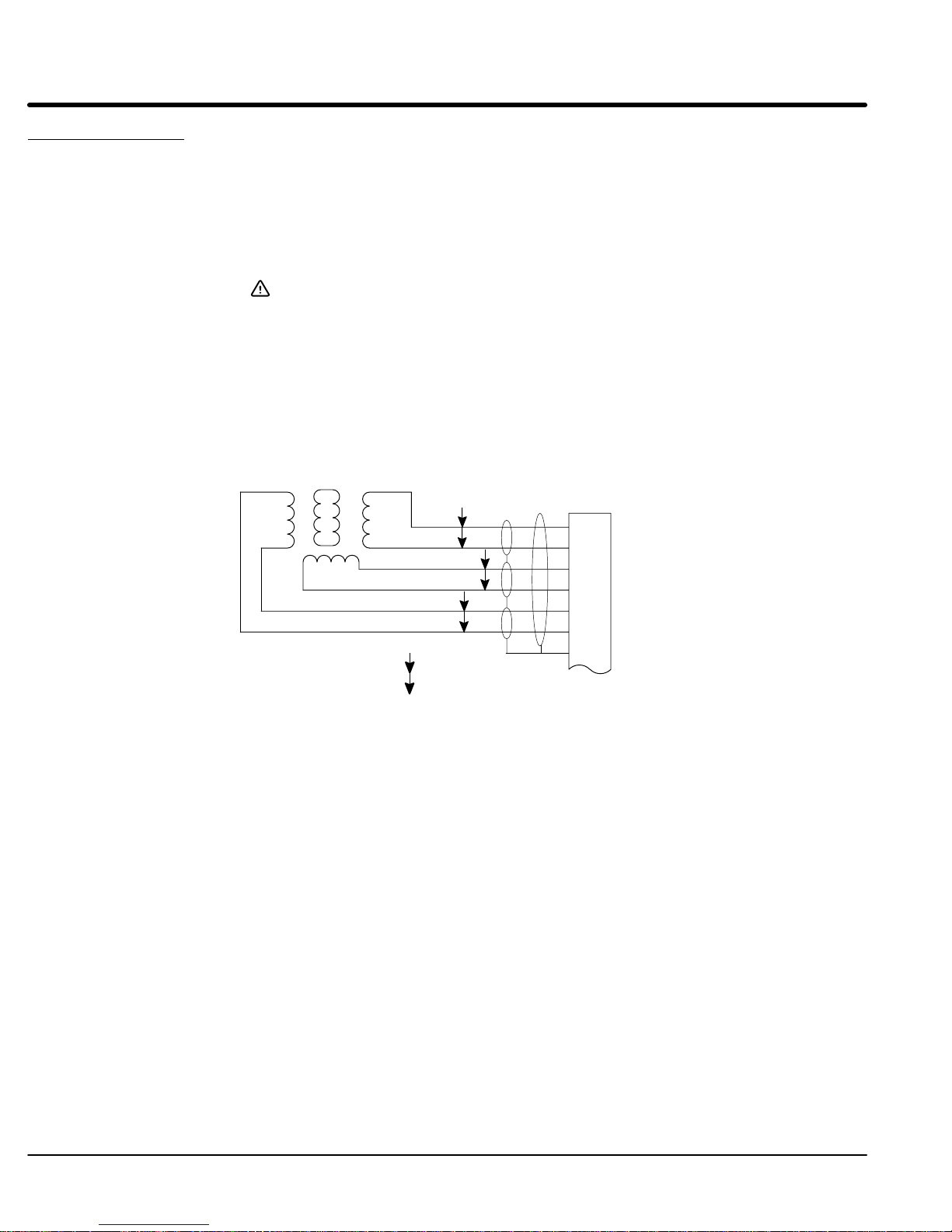
1.
Connect the SIN+ to J2-1 and SIN– to J2-6.
2.
Connect the COS+ to J2-2 and COS– to J2-7.
3.
Connect the REF+ to J2-3 and REF– to J2-8.
4.
Connect the analog ground wire to J2-13.
Figure 3-4 Resolver Cable Connections
R2
R1
S2
S4
S1S3
P
P
P
= T
wisted Pair
P
J2
1 SIN+
6 SIN–
2 COS+
7 COS–
3 REF+
8 REF– (Common)
13 AGND
3-8
Installation
MN1230
Page 20
Section 1
General Information
Simulated Encoder Output The
This output provides position information to the host controller
an overall shield.
This output simulates a 1024 ppr encoder with quadrature outputs. Counting in
quadrature will provide 4096 ppr with one index marker (CHC) per revolution. It is
recommended that this output only drive one output circuit load. Driving multiple loads is
not recommended.
control provides a simulated encoder output at connector J3 as shown in Figure 3-5.
. Use twisted pair wire with
Figure 3-5 Simulated Encoder Output
J3
CHA+
1
CHA–
6
CHB+
2
CHB–
7
CHC+
3
CHC–
8
DGND
5
4
N.A.
9 N.A.
1.
Connect J3-1 and J3-6 outputs to Host Position Controller CHA inputs.
2.
Connect J3-2 and J3-7 outputs to Host Position Controller CHB inputs.
3.
Connect J3-3 and J3-8 outputs to Host Position Controller CHC inputs.
4.
Connect the cable shields to J3-5.
P
P
To Host Position
P
P
Controller
= Twisted Pair
MN1230
Installation
3-9
Page 21

Section 1
General Information
Control Circuit Connections
Eight operating modes are available. These operating modes define the basic motor
control setup and the operation of the input and output terminals. After the circuit
connections are completed, the operating mode is selected by programming the Level 1
Input block Operating Mode parameter
•
Keypad Mode
•
Standard Run 3 Wire Mode (e.g. Potentiometer)
•
15 Speed 2 Wire Mode (e.g. Preset Speeds)
•
2 Wire
Multi
INP (e.g. 2 wire control mode)
•
3 Wire
Multi
INP (e.g. 3 wire control mode)
• Serial
•
Bipolar Speed or T
•
Process Mode
External devices are connected at the AC Servo Control connectors shown in Figure 3-3.
1.
Connect the Keypad to J4 on the control panel.
2.
Determine the operating mode for your application. Connect the remaining
control connections as shown in the diagram for that operating mode. (Refer to
Figures 3-7, 3-8, 3-9 and 3-12.)
Note:
Input connections at J1B can be wired as active High or active Low as shown
in Figure 3-6. J1B pin 19 is the Control Reference point (CREF) for the Opto
Isolated Input signals. Input signals are on J1B pins 8, 9, 10, 1
15, 16.
orque Mode (e.g. ±10VDC, ±5VDC or 4-20mA)
. A
vailable operating modes are:
1, 12, 13, 14,
3-10
Installation
MN1230
Page 22
Section 1
General Information
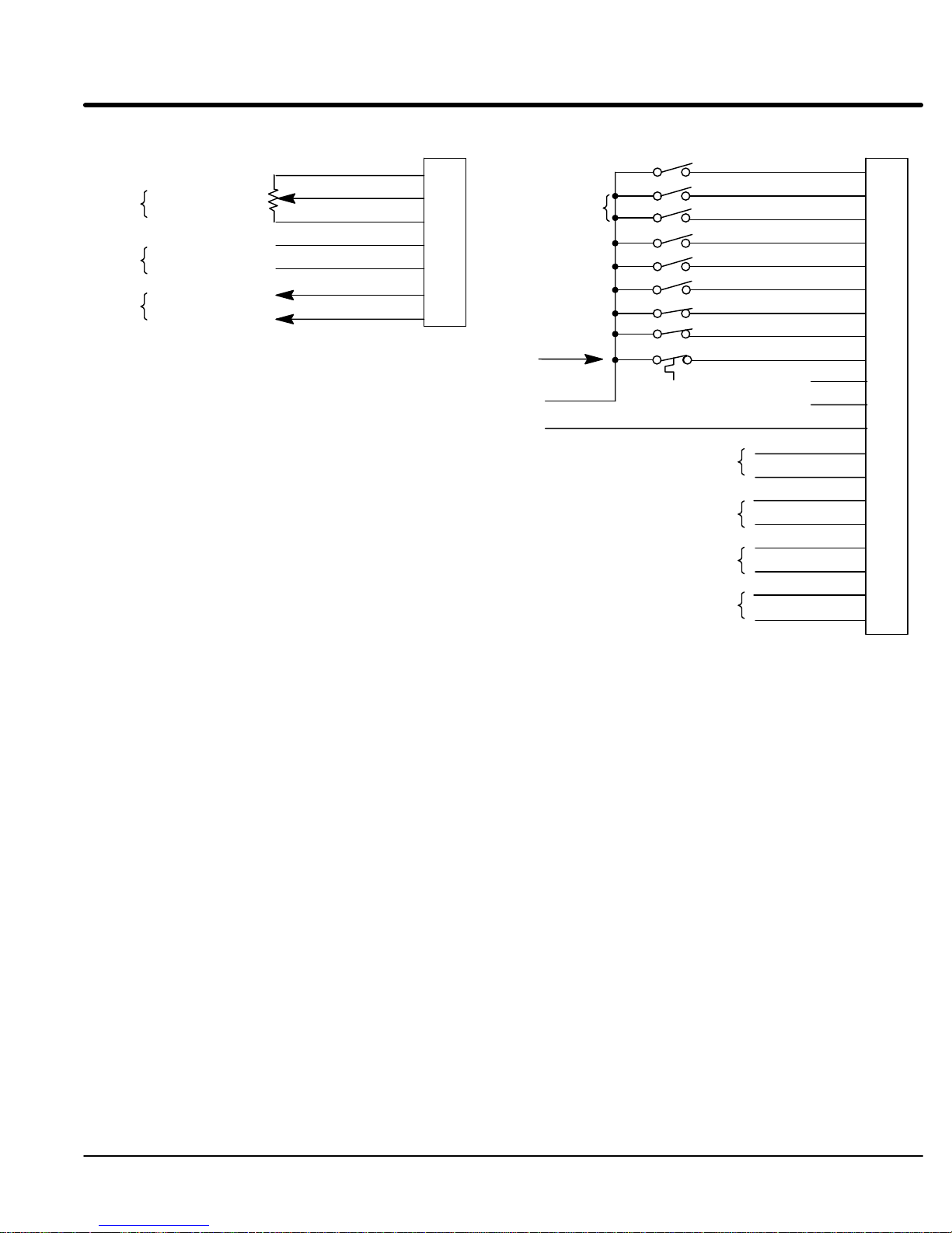
Active High/Low Description
Active Low Active High
GND
(Sink)
+24VDC
A customer supplied power source is required for operation of the Opto Inputs. The V
and GND
Active High
inputs are optional and are not provided with this control.
ext
- If pin 19 is grounded, an input is active when it is at +24VDC
(+10VDC to +30VDC).
Active Low
- If pin 19 is at +24VDC (+10VDC to +30VDC), an input is active when it
is grounded.
Figure 3-6 Active HIGH/LOW Relationship
ext
V
ext
(Source)
GND
J1B
Pin 19 - CREF
ext
Note: These
individual control of each input condition.
GND
+24VDC
pins are shown wired together
Pin 8 - Enable
Pin 9 - FWD
Pin 10 - REV
Pin 11 - IN1
Pin 12 - IN2
Pin 13 - IN3
Pin 14 - IN4
Pin 15 - IN5
Pin 16 - External Trip
. Although this can be done, each input is usually connected to a switch for
Installation
3-1
1MN1230
Page 23

Section 1
General Information
Keypad Mode
In the Keypad Operating mode:
T
o operate in the Keypad mode, set the Level 1 Input block, OPERA
parameter to KEYP
outputs (at J1A) remain active.
If the Level 2 PROTECTION block, EXTERNAL TRIP and LOCAL ENABLE INPUT
parameters remain OFF (factory setting), no terminal strip wiring is required.
1.
The External T
block, EXTERNAL TRIP parameter is set to ON. If the Level 2 PROTECTION
block, EXTERNAL TRIP parameter is programmed “ON”, make connections as
shown in Figure 3-7.
2.
The Local Enable Opto Input at J1B-8 is active if the Level 2 PROTECTION
block, LOCAL INP ENABLE parameter is set to ON. If the Level 2
PROTECTION block, LOCAL INP ENABLE parameter is programmed “ON”,
make connections as shown in Figure 3-7.
The ST
OP key can operate in two ways:
S Press ST
S Press ST
AD. In this mode, only two Opto inputs can be active. Both analog
rip Opto Input at J1B-16 is active if the Level 2 PROTECTION
OP key one time to brake or coast to stop.
OP key two times to disable control.
TING MODE
3-12
Installation
MN1230
Page 24

Section 1
General Information
Figure 3-7 Keypad Mode Connection Diagram
J1A
ANALOG GND
No
Connection
ANALOG OUT 1
Note 1
Notes:
1. Refer to Analog Outputs description in this section.
2. Refer to Opto Isolated Outputs description in this
section.
ANALOG OUT 2
1
2
3
4
5
6
7
Refer
to Figure 3-17
Customer
Supplied
+24VDC Source
GND
V
ext
ext
Note 2
OUT 1
OUT 2
OUT 3
OUT 4
ENABLE
No
Connection
EXTERNAL TRIP
CREF
OUT 1–
OUT 1+
OUT 2–
OUT 2+
OUT 3–
OUT 3+
OUT 4–
OUT 4+
N.C.
N.C.
J1B
8
9
10
11
12
13
14
15
16
17
18
19
20
21
22
23
24
25
26
27
J1B-8 CLOSED allows current to flow in the motor.
OPEN disables the control and motor coasts to a stop (if Level 2 Protection block,
LOCAL ENABLE INP is set to ON). This input is optional.
J1B-16 OPEN causes an external trip to be received by control. The control will disable and
display External Trip when programmed “ON”. If J1B-16 is connected, you must set
Level 2 Protection block, External Trip to “ON” to recognize the J1B-16 input.
MN1230
Installation
3-13
Page 25

Section 1
General Information
Standard Run 3 Wire Mode
In
standard run mode, the control is operated by the Opto Isolated inputs at J1B-8
through J1B-16 and the analog command input J1A pins 1, 2 and 3 (5KW pot, 0-5VDC or
0-10VDC). J1A-4 and J1A-5 can be used as the input (0-5VDC, 0-10VDC or 4-20mA).
The Opto inputs can be switches as shown in Figure 3-8 or logic signals from another
device. The External T
Level 2 PROTECTION block, EXTERNAL TRIP parameter is set to ON.
The motor speed command may be one of the following:
Preset Speed (J1B–14)
Command Input (Potentiometer
Dif
ferential analog input (±5VDC, ±10VDC or 4-20mA)
Make control connections as shown in Figure 3-8.
rip Opto Input at J1B-16 is active if connected as shown and the
, 0-5VDC or 0-10VDC)
3-14
Installation
MN1230
Page 26
Section 1
General Information
Figure 3-8 Standard Run 3-Wire Mode Connection Diagram
J1A
ANALOG GND
5kW Command Pot
Note 1
Note 2
Notes:
1. Refer to Analog Inputs description in this section.
Note: JP1 must be properly set for either voltage or current
operation. Refer to Figure 3-16 for jumper information.
2. Refer to Analog Outputs description in this section.
3. Refer to Opto Isolated Outputs description in this section.
ANALOG INPUT 1
POT REFERENCE
ANALOG INPUT 2+
ANALOG INPUT 2–
ANALOG OUT 1
ANALOG OUT 2
1
2
3
4
5
6
7
Refer
to Figure 3-17
+24VDC Source
Both CLOSED= Forward
Customer
Supplied
GND
V
ext
ext
Note 3
FORWARD ENABLE
REVERSE ENABLE
Closed=JOG SPEED
ACC/DEC/“S” SELECT
PRESET SPEED #1
FAULT RESET
EXTERNAL TRIP
OUT 1
OUT 2
OUT 3
OUT 4
ENABLE
STOP
N.C.
N.C.
CREF
OUT 1–
OUT 1+
OUT 2–
OUT 2+
OUT 3–
OUT 3+
OUT 4–
OUT 4+
J1B
8
9
10
11
12
13
14
15
16
17
18
19
20
21
22
23
24
25
26
27
J1B-8 CLOSED allows current to flow in the motor and produce torque.
OPEN disables the control and motor coasts to a stop.
J1B-9 Momentary CLOSED starts motor operation in the Forward direction. In JOG mode
(J1-12 CLOSED), continuous CLOSED jogs motor in the Forward direction.
J1B-10 Momentary CLOSED starts motor operation in the Reverse direction. In JOG mode
(J1-12 CLOSED), CONTINUOUS closed JOGS motor in the Reverse direction.
J1B-11 When OPEN control removes power from motor and disables. Coasts or brakes to stop
depending on Keypad Stop Mode parameter setting.
J1B-12 CLOSED places control in JOG mode, Forward and Reverse run are used to jog the
motor.
J1B-13 CLOSED selects group 2.
OPEN selects ACC / DEC / S-CURVE group 1.
J1B-14 CLOSED selects preset speed #1.
OPEN allows speed command from Analog input #1 or #2.
J1B-15 CLOSED to reset fault condition.
OPEN to run,
J1B-16 OPEN causes an external trip to be received by control. The control will disable and
display External Trip when programmed “ON”. If J1B-16 is connected, you must set
Level 2 Protection block, External Trip to “ON” to recognize the J1B-16 input.
MN1230
Installation
3-15
Page 27

Section 1
General Information
15 Speed 2-Wire Mode
Table 3-5 Switch Truth Table for 15 Speed, 2 Wire Control Mode
In this mode, 15 preset motor speeds are stored during setup and selected during
operation. Switch T
ruth T
able is defined in T
able 3-5.
Operation in the 15 Speed 2-Wire mode is controlled by the Opto Isolated inputs at
J1B-1
1 through J1B-15. The Opto inputs can be switches as shown in Figure 3-9 or logic
signals from another device. The External T
rip Opto Input at J1B-16 is active if
connected as shown and the Level 2 PROTECTION block, EXTERNAL TRIP parameter
is set to ON.
Switched inputs at J1B-1
provide Fault Reset as defined in T
Function J1B-11 J1B-12 J1B-13 J1B-14
Preset 1 Open Open Open Open
Preset 2 Closed Open Open Open
Preset 3 Open Closed Open Open
Preset 4 Closed Closed Open Open
Preset 5 Open Open Closed Open
Preset 6 Closed Open Closed Open
Preset 7 Open Closed Closed Open
Preset 8 Closed Closed Closed Open
Preset 9 Open Open Open Closed
Preset 10 Closed Open Open Closed
Preset 11 Open Closed Open Closed
Preset 12 Closed Closed Open Closed
Preset 13 Open Open Closed Closed
Preset 14 Closed Open Closed Closed
Preset 15 Open Closed Closed Closed
Fault Reset Closed Closed Closed Closed
1 through J1B-14 allow selection of 15 preset speeds and
able 3-5.
3-16
Installation
MN1230
Page 28
Section 1
General Information
Figure 3-9 15 Speed 2-Wire Mode Connection Diagram
ANALOG GND
No
Connection
ANALOG OUT 1
Note 1
Notes:
1. Refer
2.
to Analog Outputs description in this section.
Refer to Opto Isolated Outputs description in this
section.
ANALOG OUT 2
J1A
1
2
Both CLOSED= Forward
3
4
5
6
7
Both OPEN = Stop
All CLOSED= Fault
Refer to Figure 3-17
Customer
Supplied
+24VDC Source
Reset
GND
V
ext
ext
Note 2
FORWARD ENABLE
REVERSE ENABLE
SWITCH 1
SWITCH 2
SWITCH 3
SWITCH 4
ACC/DEC/“S” SELECT
EXTERNAL TRIP
OUT 1
OUT 2
OUT 3
OUT 4
ENABLE
N.C.
N.C.
CREF
OUT 1–
OUT 1+
OUT 2–
OUT 2+
OUT 3–
OUT 3+
OUT 4–
OUT 4+
J1B
8
9
10
11
12
13
14
15
16
17
18
19
20
21
22
23
24
25
26
27
J1B-8 CLOSED allows current to flow in the motor and produce torque.
OPEN disables the control & motor coasts to a stop.
J1B-9 CLOSED operates the motor in the Forward direction.
OPEN coasts brakes to stop depending on Keypad Stop mode parameter setting.
J1B-10 CLOSED operates motor in the Reverse direction.
OPEN coasts or brakes to stop depending on Keypad Stop mode parameter setting.
J1B-11 to 14 Selects programmed preset speeds as defined in Table 3-5.
J1B-15 Selects ACC/DEC group. CLOSED selects group 2. OPEN selects group 1.
J1B-16 OPEN causes an external trip to be received by control. The control will disable and
display External Trip when programmed “ON”. If J1B-16 is connected, you must set
Level 2 Protection block, External Trip to “ON” to recognize the J1B-16 input.
MN1230
Installation
3-17
Page 29

Section
1
General Information
2 Wire Multi INP Control Mode
The Opto inputs can be switches as shown in Figure 3-10 or logic signals from another
device. The External T
Level 2 PROTECTION block, EXTERNAL TRIP parameter is set to ON.
J1B-8 CLOSED allows current to flow in the motor and produce torque.
J1B-9 CLOSED to start motor operation in the Forward direction.
J1B-10 CLOSED to start motor operation in the Reverse direction.
J1B-11 CLOSED selects Analog Input #1.
Note: If Level 1 Input block, Command Select parameter is set to “Potentiometer”, then
J1B-12 CLOSED selects Start/Stop and Reset commands from the terminal strip.
J1B-13 CLOSED selects terminal strip speed source (Level 1 Input block, Command Select).
Note: When changing from keypad to terminal strip (J1B-12 or 13) the motor speed and
J1B-14 OPEN selects Preset Speed #1 regardless of the Speed Command input (J1B-13).
J1B-15 OPEN selects Preset Speed #2 regardless of the Speed Command input (J1B-13).
Note: If J1B-14 and 15 are both OPEN, Preset Speed #1 is selected.
J1B-16 OPEN causes an External Trip to be received by the control (when programmed to
J1B-19 Jumper to J1B-18 (+24VDC) for “Active Low” operation of input signals at J1B-8 to 16.
rip Opto Input at J1B-16 is active if connected as shown and the
OPEN disables the control & motor coasts to a stop.
OPEN to initiate a stop command.
OPEN to initiate a stop command.
OPEN selects the value of the Level 1 Input block, Command Select parameter.
Analog Input #1 is always selected.
OPEN selects Start/Stop and Reset commands from keypad.
OPEN selects speed command from Keypad.
direction will remain the same after the change.
(FIRESTAT).
(FREEZESTAT).
“ON”). When this occurs, the control disables and an external trip error is displayed on
the keypad display (also logged into the error log).
If J1B-16 is connected, you must set Level 2 Protection block, External Trip to “ON” to
recognize the J1B-16 input.
J1B-17 is then used as switch common.
3-18 Installation
MN1230
Page 30
Section
1
General Information
Figure 3-10 2 Wire Multi INP Mode Connection Diagram
J1A
ANALOG GND
Note 1
Note 1
Note 2
5kW
Command Pot
or 0-10VDC
±5VDC, ±10VDC
or 4-20mA
Programmable
Analog Outputs.
ANALOG INPUT 1
POT REFERENCE
ANALOG INPUT +2
ANALOG INPUT –2
ANALOG OUT 1
ANALOG OUT 2
Refer
Notes:
1. Refer to Analog Inputs description in this section.
Note: JP1 must be properly set for either voltage or current
operation. Refer to Figure 3-16 for jumper information.
2. Refer to Analog Outputs description in this section.
3. Refer to Opto Isolated Outputs description in this section.
1
2
3
4
5
6
7
to Figure 3-17.
Customer
Supplied
+24VDC Source
Both Closed=
Fault Reset
GND
V
ext
ext
Note 3
FORWARD RUN
REVERSE RUN
ANALOG
OUT 1
OUT 2
OUT 3
OUT 4
INPUT SELECT
RUN COMMAND
SPEED COMMAND
PRESET SPEED #1
PRESET SPEED #2
EXTERNAL TRIP
ENABLE
N.C.
N.C.
CREF
OUT 1–
OUT 1+
OUT 2–
OUT 2+
OUT 3–
OUT 3+
OUT 4–
OUT 4+
J1B
8
9
10
11
12
13
14
15
16
17
18
19
20
21
22
23
24
25
26
27
MN1230
Installation 3-19
Page 31

Section
1
General Information
3 Wire Multi INP Control Mode
The Opto inputs can be switches as shown in Figure 3-1
device. The External T
Level 2 PROTECTION block, EXTERNAL TRIP parameter is set to ON.
J1B-8 CLOSED allows current to flow in the motor and produce torque.
J1B-9 Momentary CLOSED to start motor operation in the Forward direction.
J1B-10 Momentary CLOSED to start motor operation in the Reverse direction.
J1B-11 OPEN causes motor to decel to stop.
J1B-12 CLOSED selects Start/Stop and Reset commands from the terminal strip.
J1B-13 CLOSED selects terminal strip speed source (Level 1 Input block, Command Select).
Note: When changing from keypad to terminal strip (J1B-12 or 13) the motor speed and
J1B-14 OPEN selects Preset Speed #1 regardless of the Speed Command input (J1B-13).
J1B-15 OPEN selects Preset Speed #2 regardless of the Speed Command input (J1B-13).
Note: If J1B-14 and 15 are both OPEN, Preset Speed #1 is selected.
J1B-16 OPEN causes an External Trip to be received by the control (when programmed to
J1B-19 Jumper to J1B-18 (+24VDC) for “Active Low” operation of input signals at J1B-8 to 16.
1 or logic signals from another
rip Opto Input at J1B-16 is active if connected as shown and the
OPEN disables the control & motor coasts to a stop.
OPEN to initiate a stop command.
OPEN to initiate a stop command.
OPEN selects Start/Stop and Reset commands from keypad.
OPEN selects speed command from Keypad.
direction will remain the same after the change.
(FIRESTAT).
(FREEZESTAT).
“ON”). When this occurs, the control disables and an external trip error is displayed on
the keypad display (also logged into the error log).
If J1B-16 is connected, you must set Level 2 Protection block, External Trip to “ON” to
recognize the J1B-16 input.
J1B-17 is then used as switch common.
3-20 Installation
MN1230
Page 32

Section
1
General Information
Figure 3-11 3 Wire Multi INP Mode Connection Diagram
J1A
ANALOG GND
Note 1
Note 1
Note 2
Notes:
1. Refer to Analog Inputs description in this section.
Note: JP1 must be properly set for either voltage or current
2. Refer to Analog Outputs description in this section.
3. Refer to Opto Isolated Outputs description in this section.
5kW
Command Pot
or 0-10VDC
±5VDC, ±10VDC
or 4-20mA
Programmable
Analog Outputs.
operation. Refer to Figure 3-16 for jumper information.
ANALOG INPUT 1
POT REFERENCE
ANALOG INPUT +2
ANALOG INPUT –2
ANALOG OUT 1
ANALOG OUT 2
Refer
to Figure 3-17.
1
2
3
4
5
6
7
Customer
Supplied
+24VDC Source
Both Closed=
Fault Reset
GND
V
ext
ext
Note 3
FORWARD RUN
REVERSE RUN
RUN COMMAND
SPEED COMMAND
PRESET SPEED #1
PRESET SPEED #2
EXTERNAL TRIP
OUT 1
OUT 2
OUT 3
OUT 4
ENABLE
STOP
N.C.
N.C.
CREF
OUT 1–
OUT 1+
OUT 2–
OUT 2+
OUT 3–
OUT 3+
OUT 4–
OUT 4+
J1B
8
9
10
11
12
13
14
15
16
17
18
19
20
21
22
23
24
25
26
27
MN1230
Installation 3-21
Page 33

Section 1
General Information
Bipolar Speed or Torque Control Mode with Multiple Parameter Sets
The
normal bipolar speed or torque control for servo motors is provided by this mode.
This mode also allows the user to store up to four (4) dif
parameters. This is important if you wish to store and use dif
dif
ferent jog speeds or to store tuning parameter values for dif
T
o use multiple parameter sets: (refer to Figure 3-12 and T
1.
Set switches J1B-13 open and J1B-14 open (Parameter T
switches J1B-9 and J1B-10 are OPEN, J1B-8 is CLOSED. Use the keypad and
enter all parameter values, and autotune as instructed later in this section. This
creates and saves the first parameter set which is numbered T
Note:
When programming each parameter set, use the ENTER key to accept and
automatically save parameter values.
2.
Set switches J1B-13 closed and J1B-14 open (Parameter T
switches J1B-9 and J1B-10 are OPEN, J1B-8 is CLOSED. Use the keypad and
enter all parameter values, and autotune as instructed later in this section. This
creates and saves the second parameter set which is numbered T
3.
Set switches J1B-13 open and J1B-14 closed (Parameter T
switches J1B-9 and J1B-10 are OPEN, J1B-8 is CLOSED. Use the keypad and
enter all parameter values, and autotune as instructed later in this section. This
creates and saves the third parameter set which is numbered T
4.
Set switches J1B-13 closed and J1B-14 closed (Parameter T
switches J1B-9 and J1B-10 are OPEN, J1B-8 is CLOSED. Use the keypad and
enter all parameter values, and autotune as instructed later in this section. This
creates and saves the final parameter set which is numbered T
ferent complete sets of operating
ferent acceleration rates,
ferent motors.
able 3-6.)
able #0). Be sure
able#0.
able #1). Be sure
able#1.
able #2). Be sure
able#2.
able #3). Be sure
able#3.
Table 3-6 Bipolar Mode Table Select Truth Table
Function J1B-13 J1B-14
Parameter Table #0 Open Open
Parameter Table #1 Closed Open
Parameter Table #2 Open Closed
Parameter Table #3 Closed Closed
3-22
Installation
MN1230
Page 34

Section 1
General Information
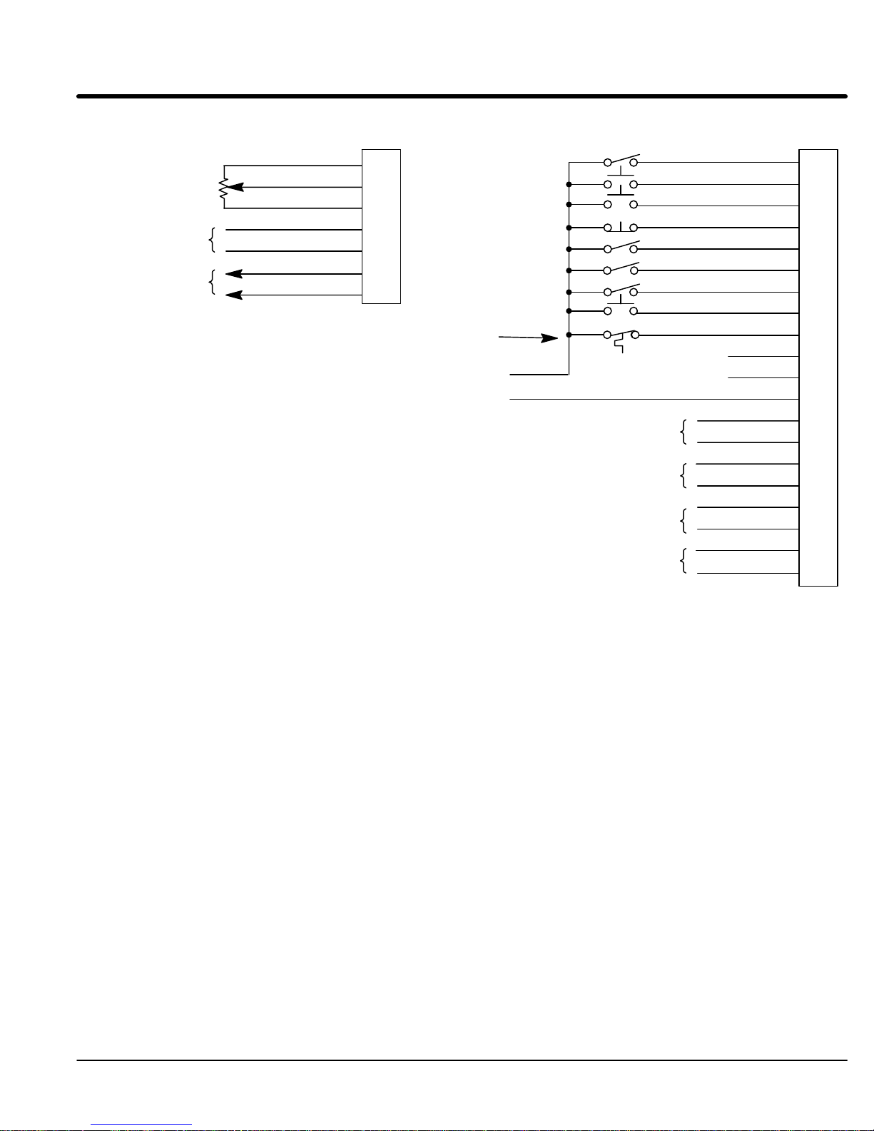
Figure 3-12 Bipolar Speed or Torque Mode Connection Diagram
J1A
ANALOG GND
No Connections
ANALOG INPUT +2
Note 1
Note 2
Notes:
1. Refer to Analog Inputs description in this section.
Note: JP1 must be properly set for either voltage or current
operation. Refer to Figure 3-16 for jumper information.
2. Refer to Analog Outputs description in this section.
3. Refer to Opto Isolated Outputs description in this section.
ANALOG INPUT –2
ANALOG OUT 1
ANALOG OUT 2
1
2
3
4
5
6
7
Refer
to Figure 3-17
Customer
Supplied
+24VDC Source
GND
V
ext
ext
Note 3
FORWARD ENABLE
REVERSE ENABLE
CLOSED=ORIENT
SPEED, TORQUE
TABLE SELECT
TABLE SELECT
FAULT RESET
EXTERNAL TRIP
OUT 1
OUT 2
OUT 3
OUT 4
ENABLE
N.C.
N.C.
CREF
OUT 1–
OUT 1+
OUT 2–
OUT 2+
OUT 3–
OUT 3+
OUT 4–
OUT 4+
J1B
8
9
10
11
12
13
14
15
16
17
18
19
20
21
22
23
24
25
26
27
J1B-8 CLOSED allows current to flow in the motor and produce torque.
OPEN disables the control & motor coasts to a stop.
J1B-9 CLOSED to enable operation in the Forward direction.
OPEN TO DISABLE Forward operation (drive will brake to a stop if a Forward command
is still present).
J1B-10 CLOSED to enable operation in the Reverse direction.
OPEN to disable Reverse operation (drive will brake to a stop if a Reverse command is
still present).
J1B-11 Causes the motor shaft to orient to a marker or external switch.
J1B-12 CLOSED puts the control in torque mode. OPEN puts the control in velocity mode.
J1B-13 & Select from four parameter tables as defined
J1B-14 in Table 3-6.
J1B-15 Momentary CLOSED to reset fault condition.
OPEN to run.
J1B-16 OPEN causes an external trip to be received by control. The control will disable and
display External Trip when programmed “ON”. If J1B-16 is connected, you must set
Level 2 Protection block, External Trip to “ON” to recognize the J1B-16 input.
MN1230
Installation
3-23
Page 35

Section
1
General Information
Process Mode Connections
The process control mode provides an auxiliary closed loop general purpose PID set
point control that is shown in Figure 3-13. The process control loop may be configured in
either of two ways.
1.
Using two (2) inputs; a set point and a process feedback input. The error signal
(between the setpoint and the feedback signals) adjusts the speed or torque of
the motor to eliminate error
2.
Using three (3) inputs; a setpoint, process feedback and feedforward inputs.
.
Instead of waiting for an error signal to develop between the setpoint and the
process feedback signals, the feedforward signal adjusts the speed or torque of
the motor to reduce the amount of error that will develop between the feedback
and setpoint inputs.
The objective of either method is to force the process feedback to be as close to the
setpoint as possible and eliminate process error
.
Two Input Configuration
For 2 input operation, several parameters must be set as follows:
1.
Level 2 Process Control block, “Process Feedback” parameter must be set to
the type of feedback signal used. The process feedback signal can be any
Analog input available at the J1A terminal strip or expansion board. Selections
are shown in Figure 3-13. A signal compatibility matrix is shown in T
2.
Level 2 Process Control block, “Setpoint Source” parameter must be set to the
able 3-7.
type of set point being used.
A.
A fixed value setpoint is a keypad programmed parameter value. T
o
program a fixed setpoint, do the following:
i.
Set the Level 2 Process Control block, “Setpoint Source” parameter
to Setpoint CMD.
ii.
Set the Level 2 Process Control block, “Setpoint CMD” parameter
to a value between –100% to +100% of the process feedback input.
B.
If a variable value setpoint is used, the Setpoint Source must be set to any
available terminal strip or expansion board input not being used for the
process feedback input. Selections are shown in Figure 3-13. A signal
compatibility matrix is shown in T
3.
Level 1 Input block “Command Select” parameter must be set to “None”.
able 3-7.
Three Input Configuration
For 3 input operation, several parameters must be set as follows:
1.
Level 2 Process Control block “Process Feedback” parameter must be set to
the type of feedback signal used. The process feedback signal can be any
Analog input available at the J1A terminal strip or expansion board. Selections
are shown in Figure 3-13. A signal compatibility matrix is shown in T
2.
Level 2 Process Control block “Setpoint Source” parameter must be set to the
able 3-7.
type of set point being used.
A.
If a fixed value setpoint is used, set the Level 2 Process Control block,
Setpoint Source parameter to “Setpoint CMD”. Set the Level 2 Process
Control block “Setpoint Command” parameter to a value between –100%
to +100% of the process feedback.
B.
If a variable value setpoint is used, set the Level 2 Process Control block,
Setpoint Source parameter to any Analog1, Analog2 or expansion board
input not being used for the process feedback input. Selections are shown
in Figure 3-13. A signal compatibility matrix is shown in T
able 3-7.
3-24 Installation
MN1230
Page 36

Section 1
General Information
3.
Level 1 Input block “Command Select” parameter must be set to the
feedforward signal type. This signal may be any Analog1, Analog2 or
expansion board input not being used for the process feedback or setpoint
source inputs. Selections are shown in Figure 3-13.
Note:
An input can only be used one time for Process Feedback, OR Setpoint
Source, OR Feedforward.
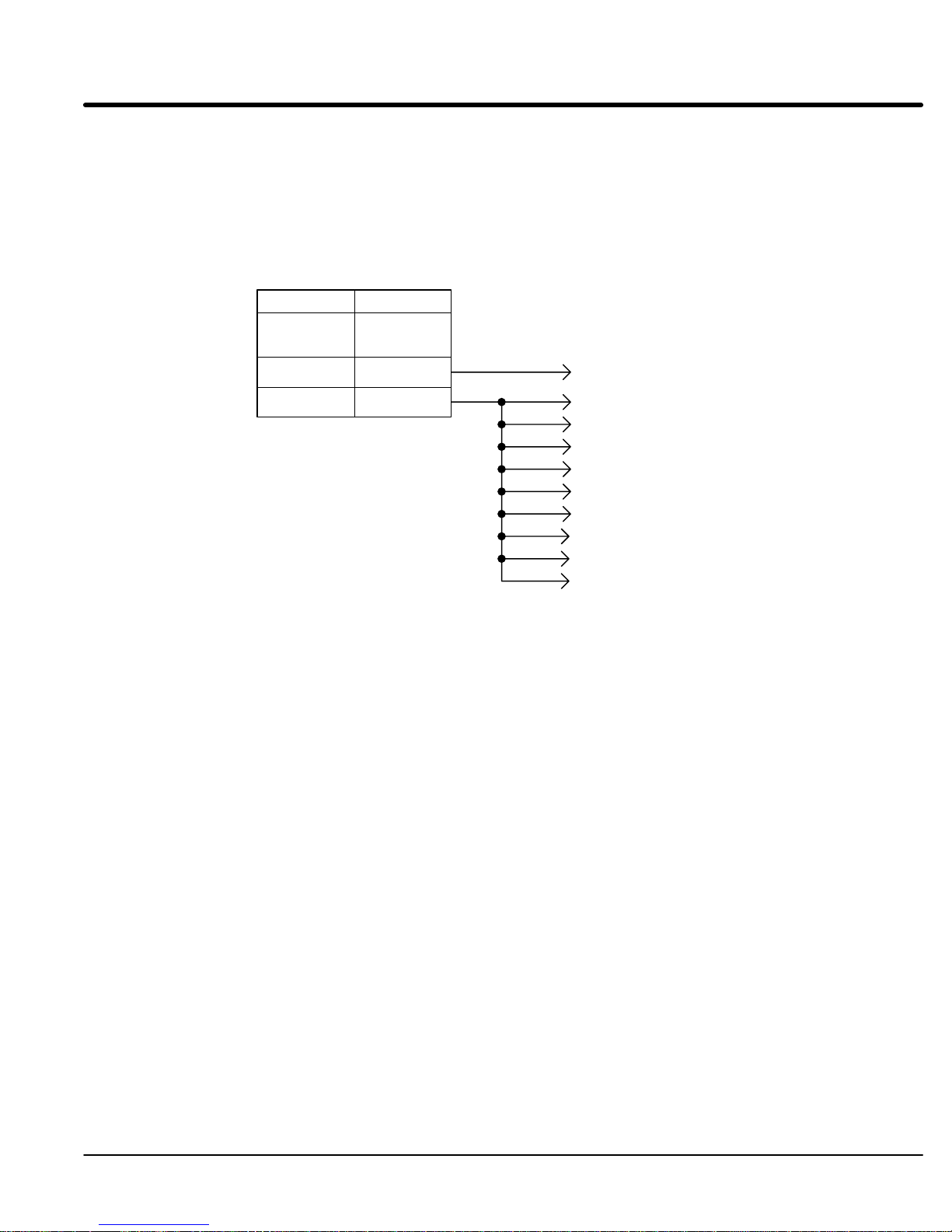
Figure 3-13 Simplified Process Control Block Diagram
SETPOINT COMMAND
PROCESS FEEDBACK
Available sources are:
Potentiometer
± 10 Volts
± 5 Volts
4 TO 20 mA
5V EXB
10V EXB
4-20mA EXB
None
PROCESS FEEDFORWARD
COMMAND SELECT
Available sources are:
Potentiometer
± 10 Volts
± 5 Volts
4 TO 20 mA
10 V w/Torq FF
EXB Pulse FOL
5V EXB
10V EXB
4-20mA EXB
Serial
None
+
–
∑
Auxiliary PID Control
Closed When Process
Mode is Enabled (J1–13)
Motor Control
ACC/DEC
S–Curve
Profiler
+
–
∑
s
+
Proportional
Gp
Existing Baldor Control System
Proportional
Gp
Differential
Gd s
Integral
Gi
s
Set Point adjustment limit
w/ integral clamp to max
limit value
Differential
Gd s
+
+
+
∑
+
+
∑
Integral
Gi
s
+
Amp
Motor
Res.
MN1230
Differentiator
Installation 3-25
Page 37

Section
Setpoint
1
General Information
Table 3-7 Process Mode Input Signal Compatibility
or
Feedforward
J1-1 & 2
J1-4 & 5
5V EXB
10V EXB
4-20mA EXB
3-15 PSI EXB
Serial
Requires
Requires expansion board EB01
Requires expansion board EB01
expansion board EB01
Conflicting inputs. Do not use same input signal multiple times.
Note:
Only one expansion board may be installed.
Specific Process Mode Outputs
Feedback
J1-1 & 2 J1-4 & 5
5V EXB 10V EXB
4-20mA
EXB
3-15 PSI
EXB
10A01 (Serial + High Resolution Analog I/O for M Series controls).
10A02 (Serial + Pulse Follower for M Series controls).
10A00 (Serial Communications for M Series controls).
Process Mode Only
, Analog Monitoring Outputs
Name Description
Process FDBK Process Feedback scaled input. Useful for observing or tuning the
process control loop.
Setpoint CMD Setpoint Command scaled input. Useful for observing or tuning the
process control loop.
Speed Command Commanded Motor Speed. Useful for observing or tuning the output of
the control loop.
Process
Name Description
Process Error CLOSED when the Process Feedback is within the specified tolerance
3-26 Installation
Mode Only
, Opto Isolated Outputs
band. OPEN when the Process Feedback is greater than the specified
tolerance band. The width of the tolerance band is adjusted by the
Level 2 Process Control block PROCESS ERR TOL parameter value.
MN1230
Page 38

Section
1
General Information
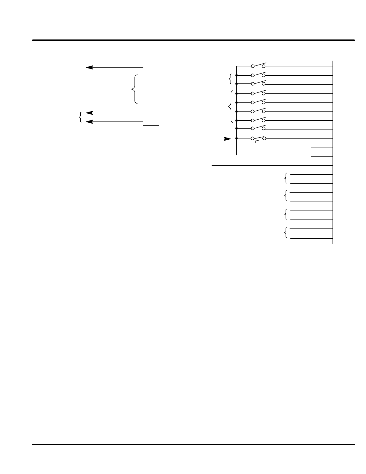
Figure 3-14 Process Mode Connection Diagram
J1A
ANALOG GND
Note 1
Note 1
Note 2
5kW
Command Pot
or 0-10VDC
±5VDC, ±10VDC
or 4-20mA
Programmable
Analog Outputs.
ANALOG INPUT 1
POT REFERENCE
ANALOG INPUT +2
ANALOG INPUT –2
ANALOG OUT 1
ANALOG OUT 2
Refer
Notes:
1. Refer to Analog Inputs description in this section.
Note: JP1 must be properly set for either voltage or current
operation. Refer to Figure 3-16 for jumper information.
2. Refer to Analog Outputs description in this section.
3. Refer to Opto Isolated Outputs description in this section.
1
2
3
4
5
6
7
to Figure 3-17.
Customer
Supplied
+24VDC Source
Both
OPEN = Stop
GND
V
ext
ext
Note 3
FORWARD ENABLE
REVERSE ENABLE
TABLE SELECT
No Connection
Process Mode Enable
JOG (FWD only)
FAULT RESET
EXTERNAL TRIP
OUT 1
OUT 2
OUT 3
OUT 4
ENABLE
N.C.
N.C.
CREF
OUT 1–
OUT 1+
OUT 2–
OUT 2+
OUT 3–
OUT 3+
OUT 4–
OUT 4+
J1B
8
9
10
11
12
13
14
15
16
17
18
19
20
21
22
23
24
25
26
27
J1B-8 CLOSED allows current to flow in the motor and produce torque.
OPEN disables the control & motor coasts to a stop.
J1B-9 CLOSED to enable operation in the Forward direction.
OPEN TO DISABLE Forward operation.
J1B-10 CLOSED to enable operation in the Reverse direction.
OPEN to disable Reverse operation.
J1B-11 OPEN=Table 0, CLOSED=Table 1.
J1B-13 CLOSED to enable the Process Mode.
J1B-14 CLOSED puts the control in JOG Mode. Control will only JOG in the forward direction.
OPEN allows PID & Feedforward Speed or Torque control.
J1B-15 Momentary CLOSED to reset fault condition.
OPEN to run.
J1B-16 OPEN causes an External Trip to be received by the control (when programmed to
“ON”). When this occurs, the control disables and an external trip error is displayed on
the keypad display (also logged into the error log).
If J1B-16 is connected, you must set Level 2 Protection block, External Trip to “ON” to
recognize the J1B-16 input.
MN1230
Installation 3-27
Page 39

Section 1
General Information
Analog Inputs and Outputs
Analog Inputs T
wo analog inputs are available: analog input #1 (J1A-1 and J1A-2) and analog input #2
(J1A-4 and J1A-5) as shown in Figure 3-15. Either analog input #1 or #2 may be
grounded provided the common mode range is not exceeded. Either analog input may
be selected in the Level 1 INPUT block, COMMAND SELECT parameter value. Analog
input #1 is selected if parameter value “POTENTIOMETER” is selected. Analog input #2
is selected if parameter value “+/–10V
olts, +/–5 V
olts or 4-20mA” is selected. Only one
analog input can be used but either may be selected.
Figure 3-15 Analog Inputs and Outputs
J1A
Command Pot
or
0-10VDC
5KW
Analog Ground
Analog Input #1
Pot Reference
Analog Input #1
Analog Input #2
Differential ±5VDC, ±10VDC
or 4-20 mA Input
Programmable 0-10VDC
Programmable 0-10VDC
Analog Input #2(+)
Analog Input #2(–)
Analog Output 1
Analog Output 2
The single ended analog input #1 is used when the control is set to Standard 3 Wire
Mode. When using a potentiometer as the command input, the Level 1 Input block
COMMAND SELECT parameter must be set to “POTENTIOMETER”.
1.
Connect the wires from the 5KW pot as shown in Figure 3-15. One end of the
pot is connected to J1A-1 (analog ground) and the other end is connected to
J1A-3 (Pot Reference).
2.
Connect the wiper of the pot to J1A-2. The voltage across terminals J1A-1 and
J1A-2 is the speed command input.
3.
A 0-10VDC speed command signal may be connected across J1A-1 and J1A-2
instead of a 5KW pot.
Analog input #2 accepts a dif
ferential command ±5VDC, ±10VDC or 4-20 mA. The
operating mode is defined in the of the Level 1 Input block COMMAND SELECT
parameter.
Note:
Analog Input #2 is used with Standard Run 3-Wire or Bipolar Control modes
and not used for the 15 Speed 2 Wire mode.
1.
Connect the Analog Input 2(+) wire to J1A-4 and the 2(–) wire to J1A-5.
2.
JP1 must be properly set for either voltage or current operation. Refer to
Figure 3-16 for jumper information.
Note:
3-28
Installation
Analog Input #2 can be connected for single ended operation by grounding
either of the inputs, provided the common mode voltage range is not
exceeded. The common mode voltage can be measured with a voltmeter
.
Apply the maximum command voltage to analog input 2 (J1A-4, 5). Measure
the AC and DC voltage across J1A-1 to J1A-4. Add the AC and DC readings
together
and DC readings together
. Measure the AC and DC voltage from J1A-1 to J1A-5. Add the AC
.
If either of these measurement totals exceeds a total of ±15 volts, then the
common mode voltage range has been exceeded. If the common mode
voltage range has been exceeded, the solution is either to change the
command voltage source or isolate the command voltage with a commercially
available signal isolator
.
MN1230
Page 40

Section 1
General Information
Figure 3-16 Jumper Locations
1
123
JP1
Jumper Jumper
JP1
Table 3-8 Jumper Positions
Position
1–2 V
2–3
Note:
Early production boards had JP2 jumper
1
Description of Jumper Position Setting
oltage Command Signal. (Factory Setting)
4–20mA Command Signal.
. If present, leave JP2 on pins 1 & 2.
MN1230
Installation
3-29
Page 41

Section 1
General Information
Analog Outputs T
wo programmable analog outputs are provided on J1A-6 and J1A-7. These outputs are
scaled ±10 VDC (1mA maximum output current) and can be used to provide real-time
status of various control conditions. The output conditions are defined in Section 4 of this
manual.
The return for these outputs is J1A-1 analog ground. Each output is programmed in the
Level 1 Output block.
1.
2.
External Trip Input Terminal
relay contact in all operating modes as shown in Figure 3-17. The thermostat or overload
relay should be a dry contact type with no power available from the contact. If the motor
thermostat or overload relay activates (opens the J1B-16 connection) the control will
automatically shut down and give an External T
Connect the External T
power supply for the opto inputs. Do not place these wires in the same conduit as the
motor power leads.
T
o activate the External T
must be set to “ON”.
Figure 3-17 Motor Temperature Relay
UVW
Connect the Output #1 wires to J1A-6 and J1A-1.
Connect the Output #2 wires to J1A-7 and J1A-1.
J1B-16 is available for connection to a normally closed thermostat or overload
rip fault.
rip Input wires to J1B-16 and GND
rip input, the Level 2 Protection block, External T
Customer Supplied
Source Voltage
of the customer provided
ext
rip parameter
Note: Add appropriate rated
protective device for AC relay
(snubber) or DC relay (Diode).
External or remote motor
overload protection may be
required by National Electrical
Code or equivalent.
*M *M *M
W
V
U
* Motor
G
Motor Thermostat Leads
*
J1B
CR1
Do not run these wires in
same conduit as motor
leads or AC power wiring.
Optional components not provided with control.
*
16
TO GND
External Trip
of Customer Supply
ext
3-30
Installation
MN1230
Page 42

Section 1
General Information
Opto-Isolated Outputs Four
J1B-27. See Figure 3-18.
The Opto-isolated outputs may be configured for sinking or sourcing 50 mA each.
However
common when active is 1.0 VDC (TTL compatible). The Opto-isolated outputs may be
connected in dif
If the opto outputs are used to directly drive a relay
minimum should be connected across the relay coil.
See Electrical Noise Considerations in Section 5 of this manual.
Each Opto Output is programmed in the Level 1 Output programming block.
Figure 3-18 Opto-isolated Output Configurations
+
Optional Customer Supplied
Optional Customer
Supplied Relays
+24VDC Source
–
Using External Supply
(Sinking the Relay)
programmable Opto-isolated outputs are available at terminals J1B-20 through
, all must be configured the same. The maximum voltage from opto output to
ferent ways as shown in Figure 3-18.
, a flyback diode rated at 1A, 100 V
1.
Connect OPT
2.
Connect OPT
3.
Connect OPT
4.
Connect OPT
20 OUT1-
21 OUT1+
22 OUT2-
23 OUT2+
24 OUT3-
25 OUT3+
26 OUT4-
27 OUT4+
O OUT #1 wires to J1B-20 and J1B-21.
O OUT #2 wires to J1B-22 and J1B-23.
O OUT #3 wires to J1B-24 and J1B-25.
O OUT #4 wires to J1B-26 and J1B-27.
+
Optional Customer Supplied
Optional Customer
Supplied Relays
+24VDC Source
–
Using External Supply
(Sourcing the Relay)
20 OUT1-
21 OUT1+
22 OUT2-
23 OUT2+
24 OUT3-
25 OUT3+
26 OUT4-
27 OUT4+
MN1230
Note: Shows
typical flyback diode rated at least 1Amp/100V (1N4002) across each
relay coil (if coil does not have built in flyback).
Installation
3-31
Page 43

Section 1
General Information
Pre-Operation Checklist Check
CAUTION: After completing the installation but before you apply power
W
Check of Motors and Couplings
of electrical items.
, be
sure to check the following items.
1.
Measure the AC line voltage and verify it matches the control rating.
2.
Inspect all power connections for accuracy
compliance to codes.
3. V
erify control and motor are grounded to each other and the control is
connected to earth ground.
4.
Check all signal wiring for accuracy
5.
Be certain all brake coils, contactors and relay coils have noise suppression.
This should be an R-C filter for AC coils and reverse biased diodes for DC coils.
MOV type transient suppression is not adequate.
ARNING: Make sure that unexpected operation of the motor shaft during start
up will not cause injury to personnel or damage to equipment.
1. V
erify freedom of motion for all motor shafts.
2. V
erify that all motor couplings are tight without backlash.
3. V
erify the holding brakes if any, are properly adjusted to fully release.
.
, workmanship and tightness and
3-32
Installation
MN1230
Page 44

Section 1
General Information
Power-Up Procedure This
This will allow you to prove the motor and control operation. Y
understanding of the keypad programming & operation procedures.
Initial Conditions
Be sure the Control, Motor and DB resistor are wired according to the procedures
described in this section. Become familiar with the keypad programming and keypad
operation of the control as described in Section 4 of this manual.
procedure will help get your system up and running in the keypad mode quickly
ou should have an
Note:
The control terminal strip does not require any connections to operate in the
Keypad mode (with factory preset parameter values).
1.
Disconnect the load (including coupling) from the motor shaft, if possible.
2. V
erify that any enable inputs to J1B-8 are open.
3. T
urn power on. Be sure no errors are displayed.
4.
Set the Level 1 Input block, Operating Mode to “KEYP
5.
Enter the following motor data in the Level 2 Motor Data block parameters:
MOT
OR RA
MOT
OR POLES
Use the following:
RESOL
6.
At the Level 2 Motor Data block, go to CALC Presets and select YES (using the
Y
key). Press ENTER and let the control calculate the preset values for the
parameters that are necessary for control operation.
7.
If the load cannot be disconnected, refer to Section 6 and manually tune the
control. After manual tuning, proceed with steps 12 through 16.
TED AMPS (from motor nameplate)
BSM 50/63/80 = 4 poles
BSM 90/100 = 8 poles
BSM 4F/6F/8F = 8 poles
VER SPEEDS (Preset is “One”)
AD”.
.
W
ARNING: The motor shaft will rotate during the autotune procedure. Be
certain that unexpected motor shaft movement will not cause injury
to personnel or damage to equipment.
8.
Go to Level 2 Autotune block, and do the following tests:
CMD OFFSET TRIM
CUR LOOP COMP
RESOL
9.
Remove all power from the control.
10.
Couple the motor to its load.
11. T
urn power on. Be sure no errors are displayed.
12.
Set the Level 2 Output Limits block, “MIN OUTPUT SPEED” parameter
13.
Set the Level 2 Output Limits block, “MAX OUTPUT SPEED” parameter
14.
Go to Level 2 Autotune block, and do the SPD CNTRLR CALC test.
15.
Run the drive from the keypad using either the JOG mode, keypad entered
speed commands or speed commands using the arrow keys.
16.
Select and program additional parameters to suit your application.
The control is now ready for use the in keypad mode. If a dif
desired, refer to Section 3 Control Connections and Section 4 Programming and
Operation.
VER ALIGN
ferent operating mode is
.
.
MN1230
Installation
3-33
Page 45

Section 1
General Information
3-34
Installation
MN1230
Page 46

Section 4
Programming and Operation
Overview
The keypad is used to program the control parameters; to operate the motor when
programmed for the Keypad operating mode; and to monitor the status and outputs of the
control by accessing the display options, diagnostic menus and the fault log.
JOG - (Green) lights when Jog is active.
FWD - (Green) lights when FWD direction is commanded.
REV - (Green) lights when REV direction is commanded.
STOP - (Red) lights when motor STOP is commanded.
Indicator Lights
JOG - Press JOG to select the
preprogrammed jog speed. After the jog
key has been pressed, use the FWD or
REV keys to run the motor in the
direction that is needed. The JOG key is
only active in the local mode.
FWD - Press FWD to initiate forward
rotation of the motor. This key is only
active in the Keypad or local mode.
REV - Press REV to initiate reverse
rotation of the motor. This key is active
only in the Keypad or local mode.
STOP - Press STOP one time to initiate
a stop sequence. Depending on the
setup of the control, the motor will either
regen or coast to a stop. This key is
operational in all modes of operation
unless it has been disabled by the
Keypad Stop parameter in the Keypad
(programming) Setup Block. Press
STOP twice to disable control (coast to
stop).
Note: If the control is operating in
remote mode and the stop key
is pressed the control will
change to the local mode when
the stop command is initiated.
To resume operation in the
remote mode, press the LOCAL
key.
LOCAL - Press LOCAL to change
between the local (keypad) and remote
operation. When the control is in the
local mode all other external commands
to the J1B terminal strip will be ignored
with the exception of the external trip
input.
Figure 4-1 Keypad
DISP - Press DISP to return to display
mode from programming mode. Provides
operational status and advances to the
next display menu item including the
diagnostic screens.
SHIFT - Press SHIFT in the program
mode to control cursor movement.
Pressing the SHIFT key once moves the
blinking cursor one character position to
the right. While in program mode, a
parameter value may be reset to the
factory preset value by pressing the
SHIFT key until the arrow symbols at the
far left of the keypad display are flashing,
then press an arrow key. In the display
mode the SHIFT key is used to adjust
the keypad contrast.
RESET - Press RESET to clear all fault
messages (in local mode). Can also be
used to return to the top of the block
programming menu without saving any
parameter value changes.
Keypad Display -
information during Local or Remote
operation. It also displays information
during parameter setup and fault or
Diagnostic Information.
Displays status
PROG - Press PROG to enter the
program mode. While in the program
mode the PROG key is used to edit a
parameter setting.
Y - (UP Arrow)
Press Y to change the value of the
parameter being displayed. Pressing Y
increments the value to the next greater
value. Also, when the fault log or
parameter list is displayed, the Y key will
scroll upward through the list. In the
local mode pressing the Y key will
increase motor speed to the next greater
value.
ENTER - Press ENTER to save
parameter value changes and move
back to the previous level in the
programming menu. In the display mode
the ENTER key is used to directly set the
local speed reference. It is also used to
select other operations when prompted
by the keypad display.
B - (Down Arrow)
Press B to change the value of the
parameter being displayed. Pressing B
decrements the value to the next lesser
value. Also, when the fault log or
parameter list is displayed, the B key will
scroll downward through the list. In the
local mode pressing the B key will
decrease motor speed to the next lower
value.
MN1230
Programming
& Operation 4-1
Page 47

Display Mode During
Display shows the status of the control as in the following example.
normal operation, the control is in the DISPLA
Y MODE. In this mode, the Keypad
Motor Status
Control Operation
The
DISPLA
Y MODE is used to view DIAGNOSTIC INFO and the F
description of how to do these tasks are described on the following pages.
Adjusting Display Contrast
When AC power is applied to the control the keypad should display the status of the
control. If there is no visible display, use the following procedure to adjust the contrast of
the display
. (Contrast may be adjusted in display mode when motor is stopped or
running).
Action Description Display Comments
Apply Power No visible display
Press DISP Key Places control in display mode
Press SHIFT SHIFT Allows display contrast
Press Y or B Key
Press ENTER Saves level of contrast and exits
adjustment
Adjusts display intensity
to display mode
Output Condition
Value and Units
Typical display
AUL
T LOG. The
4-2
Programming & Operation
MN1230
Page 48

Display Mode
Continued
Display Screens & Diagnostic Information Access
Action Description Display Comments
Apply Power Logo display for 5 seconds.
Display mode showing motor
speed.
Press DISP key First screen in Display Mode.
Press DISP key Scroll to diagnostic info block.
Press ENTER key Access diagnostic information. Displays commanded speed,
Press DISP key Display mode showing control
temperature.
Press DISP key Display mode showing bus
voltage.
Press DISP key Display mode showing %
overload current remaining.
Press DISP key Display mode showing opto
inputs & outputs state.
0=Open, 1=Closed.
Press DISP key Display mode showing actual
drive running time.
No faults present. Local keypad
mode. If in remote/serial mode,
press local for this display.
direction of rotation, Local/
Remote.
Displays operating temperature in
degrees C.
Opto Inputs states (Left);
Opto Outputs states (Right).
HR.MIN.SEC format.
Press DISP key Display mode showing operating
Press DISP key Display mode showing continuous
Press DISP key Display mode showing which
Press DISP key Display mode showing motor
Press DISP key Display mode showing parameter
Press DISP key Display mode showing software
Press DISP key Displays exit choice. Press ENTER to exit diagnostic
zone, voltage and control type.
amps; PK amps rating; amps/volt
scale of feedback, power base ID.
Group1 or 2 expansion boards
are installed.
shaft revolutions from the REV
home set point.
table selected.
version and revision installed in
the control.
XXX-X.XX
information.
MN1230
Programming
& Operation 4-3
Page 49

Display Mode
Fault Log Access When
Continued
a fault condition occurs, motor operation stops and a fault code is displayed on the
Keypad display
. The control keeps a log of up to the last 31 faults. If more than 31 faults
have occurred the oldest fault will be deleted from the fault log to make room for the
newest fault. To access the fault log perform the following procedure:
Action Description Display Comments
Apply Power Logo display for 5 seconds.
Display mode showing motor
speed.
Press DISP key Press DISP several times to scroll
Press ENTER key Display first fault type and time
Press key
Press ENTER key Return to display mode. Display mode stop key LED is on.
to the Fault Log entry point.
fault occurred.
Scroll through fault messages.
Display mode.
1 = Most Recent fault displayed.
2 = Next most recent etc.
If no messages, the fault log exit
choice is displayed.
4-4
Programming & Operation
MN1230
Page 50

Program Mode The
From the Display Mode press the PROG key to access the Program Mode.
Parameter
Parameter Status
Program Mode is used to:
1.
Enter or change parameter values.
2.
Enter Motor Data.
3.
Autotune the motor
Note:
When a parameter is selected, alternately pressing the Disp and Prog keys
.
will toggle between the Display Mode and the selected parameter
parameter is selected for programming, the keypad display provides the
following information:
. When a
Value and Units
Parameter
left corner of the keypad display
Status
. All programmable parameters are displayed with a “P:” in the lower
. If a parameter is displayed with a “V
:”, the parameter
value may be viewed but not changed while the motor is operating. If the parameter is
displayed with an “L:”, the value is locked and the security access code must be entered
before its’ value can be changed.
Parameter Blocks Access for Programming
Use
the following procedure to access parameter blocks to program the control.
Action Description Display Comments
Apply Power Keypad Display shows this
Press PROG key Press ENTER to access Preset
Press Y or B key
opening message.
If no faults and programmed for
LOCAL operation.
If no faults and programmed for
REMOTE operation.
If fault is displayed, refer to the
Troubleshooting section of this
manual.
Scroll to the ACCEL/DECEL
block.
Logo display for 5 seconds.
Display mode.
Display mode.
Speed parameters.
Press ENTER to access Accel
and Decel rate parameters.
Press Y or B key
Press ENTER key First Level 2 block display.
Press Y or B key
Press ENTER key Return to display mode.
Scroll to the Level 2 Block.
Scroll to Programming Exit menu.
MN1230
Press ENTER to access Level 2
Blocks.
Press ENTER to return to Display
mode.
Programming
& Operation 4-5
Page 51

Program Mode
Continued
Changing Parameter Values when Security Code Not Used
Use
the following procedure to program or change a parameter already programmed into
the control when a security code is not being used.
The example shown changes the operating mode from Keypad to Bipolar
Action Description Display Comments
Apply Power Keypad Display shows this
opening message.
.
Logo display for 5 seconds.
If no faults and programmed for
LOCAL operation.
Press PROG key Access programming mode.
Press Y or B key
Press PROG key Access Operating Mode. Keypad mode shown is the
Press Y key
Press ENTER or PROG Save selection to memory. Press RESET to cancel selection
Press Y key
Press ENTER key Return to Input Block.
Press DISP key Return to Display Mode. Typical display mode.
Scroll to Level 1 Input Block.
Then press ENTER to access
Input Block.
Scroll to make your selection.
Scroll to menu exit.
Display mode. Stop LED on.
Press ENTER to access INPUT
block parameter.
factory setting.
Typical selection.
without saving to memory.
4-6
Programming & Operation
MN1230
Page 52

Program Mode
Continued
Reset Parameters to Factory Settings
Sometimes
this procedure to do so.
Action Description Display Comments
Apply Power Keypad Display shows this
opening message.
it is necessary to restore the parameter values to the factory settings. Follow
Note:
All specific application parameters already programmed will be lost when
resetting the control to factory settings.
Logo display for 5 seconds.
If no faults and programmed for
LOCAL operation.
Press PROG key Enter program mode.
Press Y or B key
Press ENTER key Select Level 2 Blocks.
Press Y or B key
Press ENTER key Select Miscellaneous block.
Press Y key
Press ENTER key Access Factory Settings
Press Y key
Press ENTER key Restores factory settings. “Loading Presets” is first message
Press Y key
Scroll to Level 2 Blocks.
Scroll to the Miscellaneous block.
Scroll to Factory Settings
parameter.
parameter.
Scroll to YES, to choose original
factory settings.
Scroll to menu exit.
Display mode. Stop LED on.
V represents blinking cursor.
“Operation Done” is next
“No” is displayed last.
Press ENTER key Return to display mode. Display mode. Stop LED on.
MN1230
Programming
& Operation 4-7
Page 53

Program Mode
Continued
Initialize New Software EEPROMs
After
new EEPROMs are installed, the control must be initialized to the new software
version and memory locations. Use the following procedure to Initialize the EEPROMs.
Action Description Display Comments
Apply Power Keypad Display shows this
opening message.
Logo display for 5 seconds.
If no faults and programmed for
LOCAL operation.
Press PROG key Enter program mode.
Press Y or B key
Press ENTER key Select Level 2 Blocks.
Press Y or B key
Press ENTER key Select Miscellaneous block.
Press Y key
Press ENTER key Access Factory Settings
Press Y key
Press ENTER key Restores factory settings. “Loading Presets” is first message
Press Y key
Scroll to Level 2 Blocks.
Scroll to the Miscellaneous block.
Scroll to Factory Settings
parameter.
parameter.
Scroll to YES, to choose original
factory settings.
Scroll to menu exit.
Display mode. Stop LED on.
V represents blinking cursor.
“Operation Done” is next
“No” is displayed last.
Press ENTER key Return to display mode. Display mode. Stop LED on.
Press Y key
Press ENTER key Access diagnostic information. Displays commanded speed,
Press DISP key Display mode showing software
Press DISP key Displays exit choice. Press ENTER to exit diagnostic
4-8
Programming & Operation
Scroll to diagnostic info block.
version and revision installed in
the control.
direction of rotation, Local/
Remote and motor speed.
Verify new software version.
XXX-X.XX
information.
MN1230
Page 54

Parameter Adjustments To
structure shown in T
first programming block to be displayed is “Preset Speeds”. Use the Up (Y) and Down
(B
within a programing block.
T
Block V
programmable range and factory preset value for each parameter
to record your settings for future reference.
make programming easier
, parameters have been arranged into the two level
able 4-1. Press the PROG key to enter the programming mode. The
) arrows to scroll through the parameter blocks. Press ENTER to access parameters
ables 4-2 and 4-3 provide an explanation of each parameter
. A complete Parameter
alues list is located in Appendix A of this manual. This list defines the
. The list has a space
Table 4-1 List of Parameters
LEVEL 1 BLOCKS
Preset Speeds Input Output Limits Motor Data
Preset Speed #1 Operating Mode MIN Output Speed Motor Rated Amps
Preset Speed #2 Command Select MAX Output Speed Motor Poles
Preset Speed #3 ANA CMD Inverse PK Current Limit Resolver Speeds
Preset Speed #4 ANA CMD Offset PWM Frequency CALC Presets
Preset Speed #5 ANA 2 Deadband CUR Rate Limit
Preset Speed #6 ANA 1 CUR LIMIT
Preset Speed #7 Process Control
Preset Speed #8 Output Custom Units Process Feedback
Preset Speed #9 Opto Output #1 Decimal Places Process Inverse
Preset Speed #10 Opto Output #2 Value at Speed Setpoint Source
Preset Speed #11 Opto Output #3 Units of Measure Setpoint Command
Preset Speed #12 Opto Output #4 Set PT ADJ Limit
Preset Speed #13 Zero SPD Set PT Protection Process ERR TOL
Preset Speed #14 At Speed Band Overload Process PROP Gain
Preset Speed #15 Set Speed External Trip Process INT Gain
Analog Out #1 Local Enable Input Process DIFF Gain
Accel / Decel Rate Analog Out #2 Following Error Follow I:O Ratio
Accel Time #1 Analog #1 Scale Follow I:O OUT
Decel Time #1 Analog #2 Scale Miscellaneous Master Encoder
S-Curve #1 Position Band Restart Auto/Man
Accel Time #2 Restart Fault/Hr Communications
Decel Time #2 Brushless Control Restart Delay Protocol
S-Curve #2 Resolver Align Factory Settings Baud Rate
Speed Filter Homing Speed Drive Address
Jog Settings Feedback Align Homing Offset
Jog Speed Current PROP Gain
Jog Accel Time Current INT Gain Security Control
Jog Decel Time Speed PROP Gain Security State Auto-Tuning
Jog S-Curve Time Speed Int Gain Access Timeout CALC Presets
Speed DIFF Gain Access Code
Keypad Setup Position Gain CUR Loop Comp
Keypad Stop Key Resolver Align
Keypad Stop Mode SPD CNTRLR CALC
Keypad Run FWD
Keypad Run REV
Keypad Jog FWD
Keypad Jog REV
LEVEL 2 BLOCKS
CMD Of
fset Trim
MN1230
Programming
& Operation 4-9
Page 55

Table 4-2 Level 1 Parameter Block Definitions
g
g
than the minimum s eed arameter setting
J
J
Block Title Parameter Description
PRESET
SPEEDS
ACCEL/DECEL
RATE
JOG SETTINGS Jog Speed Jog Speed changes motor speed to a new preset value for jog mode. To cause motor to
Preset Speeds
#1 – #15
Accel Time #1,2
Decel Time #1,2
S-Curve #1,2
Jog Accel Time
og Decel Time
Jog S-Curve
Allows selection of 15 predefined motor operating speeds.
Each speed may be selected using external switches connected to J1B-11, J1B-12,
J1B-13 and J1B-14.
For motor operation, a motor direction command must be given along with a preset
speed command.
Accel time is the number of seconds required for the motor to increase at a linear rate
from 0 RPM to the RPM specified in the “Max Output Speed” parameter in the Level 2
Output Limits block. Accel Time #2 is accessible in Standard Run 3 Wire and 15
Speed 2 Wire modes only.
Example: Maximum Output Speed =1000 RPM; Preset Speed = 500 RPM, Accel
Time=10 Sec.
In this example, motor will be at 500 RPM 5 seconds after commanded because preset
is half the max speed.
Decel time is the number of seconds required for the motor to decrease at a linear rate
from the speed specified in the “Max Output Speed” parameter to 0 RPM.
S-Curve is a percentage of the total Accel or Decel time and provides smooth starts and
stops.
Figure 4-2 illustrates how motor acceleration is changed using a 40% S-Curve.
0% represents no “S” and 100% represents full “S” with no linear segment.
Note: Accel #1, Decel #1 and S-Curve #1 are associated together. Likewise,
Accel #2, Decel #2 and S-Curve #2 are associated together. These
associations can be used to control any Preset Speed or External Speed
Command (Pot).
Note: If faults (motor trips) occur during rapid Accel or Decel, selecting an S-curve
may eliminate the faults without affecting the overall ramp time.
operate at Jog Speed the FWD or REV key must be pressed or external command
Forward (J1B-9) or Reverse (J1B-10). The motor will run at jog speed until FWD or
REV key is released or external command signal is removed. Jog speed can be less
.
than the minimum speed parameter settin
.
Jog Accel Time changes the Accel Time to a new preset value for jog mode.
og Decel Time changes the Decel Time to a new preset value for jog mode.
p
Jog S-Curve changes the S-Curve to a new preset value for jog mode.
40%
Curve
0%
Curve
20
%
Output Speed
Accel Time0Max
Accel S-Curves
4-10
Programming & Operation
20
%
Figure 4-2 S-Curve Example
Output Speed
40%
Curve
20
%
Decel Time0Max
Decel S-Curves
0%
Curve
20
%
MN1230
Page 56

Table 4-2 Level 1 Parameter Block Definitions
Note: In REGEN mode, it is ossible to cause an Overvoltage T
ri if
Block Title Parameter Description
KEYPAD SETUP Keypad Stop Key
Keypad Stop Mode
Keypad Run FWD
Keypad Run REV
Keypad Jog FWD
Keypad Jog REV
INPUT
Operating Mode
Command Select
ANA CMD Inverse “OFF” will cause a low input voltage (e.g. 0VDC) to be a low motor speed command and
ANA CMD Offset
ANA 2 Deadband
ANA 1 CUR Limit Allows the 5V input at J1A-2 (referenced to J1A-1) to be used for reduction of the
Allows keypad “STOP” key to initiate motor stop during remote or serial operation (if
Stop key is programmed to Remote ON). If active, pressing “STOP” automatically
selects Local mode and initiates the stop command.
Causes the motor to “COAST” to a stop or “REGEN” to a stop. In COAST, the motor is
turned off and allowed to coast to a stop. In REGEN, the voltage and frequency to the
motor is reduced at a rate set by “Decel Time”.
Note: In
Makes the keypad “FWD” key active in Local mode.
Makes the keypad “REV” key active in Local mode.
Makes the keypad “FWD” key active in Local Jog mode.
Makes the keypad “REV” key active in Local Jog mode.
Eight
“Operating Modes” are available. Choices are: Keypad, Standard Run, 15 Speed, 2 Wire
Multi INP, 3 Wire Multi INP, Serial, Bipolar or Process Control. External connections
to the control are made at the J1B terminal strip (wiring diagrams are shown in
Section 3).
Selects the external speed reference to be used.
easiest method of speed
The
J1A-1, J1A-2, and J1A-3.
±5 or ±10VDC input command can be applied to J1A-4 and J1A-5.
T
O 20 mA - If
4
4-20mA selections at J1A-4 and J1A-5 should be considered. Current loop allows
long cable lengths without attenuation of the command signal.
Note: JP1 jumper on the main control board must be in the correct position for current
or voltage operation. Refer to Figure 3-16.
VOLT W/T
10
torque feedforward input at J1A-1, 2 and 3 to set a predetermined amount of torque
inside the rate loop with high gain settings.
PULSE FOL - selects optional
EXB
board if installed.
5V EXB - selects optional High Resolution I/O expansion board if installed.
10V EXB - selects optional High Resolution I/O expansion board if installed.
4-20mA EXB - selects optional High Resolution I/O expansion board if installed.
3-15 PSI EXB selects optional 3-15 PSI expansion board if installed.
Tachometer EXB- selects optional DC Tachometer expansion board if installed.
Serial -selects optional Serial Communications expansion board if installed.
a maximum input voltage (e.g. 10VDC) to be a maximum motor speed command.
“ON” will cause a low input voltage (e.g. 0VDC) to be a maximum motor speed
command and a maximum input voltage (e.g. 10VDC) to be a low motor speed
command.
Provides an offset to the Analog Input to minimize signal drift. For example, if the
minimum speed signal is 1VDC (instead of 0VDC) the ANA CMD Offset can be set to
-10% so the minimum voltage input is seen by control as 0VDC.
Allows a defined range of voltage to be a deadband. A command signal within this
range will not affect the control output. The deadband value is the voltage above and
below the zero command signal level.
programmed current limit parameter for torque trimming during operation.
- Continued
REGEN mode, it is possible to cause an Overvoltage T
“REGEN” to stop decelerates the motor too quickly
rip if
. If a fault
occurs, increase the DECEL time.
control is to select POTENTIOMETER and connect a 5KW pot to
long distance is required between the external speed control and the control, the
ORQ FF - when a dif
ferential command is present at J1A-4 and 5, allows additional
Master Pulse Reference/Isolated Pulse Follower expansion
Programming
& Operation 4-1
1MN1230
Page 57

Table 4-2 Level 1 Parameter Block Definitions
Block Title Parameter Description
OUTPUT OPTO OUTPUT
#1 – #4
Zero SPD Set PT Sets the RPM at which the Zero Speed opto output becomes active (turns on). When
At Speed Band The At Speed Band serves two Opto Output Conditions and the Level 2 Protection block
Set Speed Point Sets the RPM at which the AT Set Speed opto output becomes active (turns on). When
Four optically isolated digital outputs that have two operating states, logical High or Low.
Each output may be configured to any of the following conditions:
Condition Description
Ready - Active when power is applied and no faults are present.
Zero Speed - Active when output speed is below the programmed value of the
At Speed - Active when output speed is within the speed range defined by the
Overload - Active during an Overload fault caused by a time out when output
Keypad Control - Active when control is in Local keypad control.
At Set Speed - Active when output speed is at or above the “Set Speed Point” Level
Fault - Active when a fault condition is present.
Following ERR - Active when the motor speed is outside the user specified
Motor Direction - Active High when REV direction command received. Active Low
Drive On - Active when control is “Ready” (has reached excitation level and
CMD Direction - Active at all times. Logical output state indicates Forward or
AT Position - Active during a positioning command when control is within the
Over Temp Warn - Active when control heatsink temperature is within 3°C of the INT.
Process Error - Active when the process feedback signal is outside the process error
Drive Run - Active when drive is Ready, Enabled, Speed or Torque command is
the speed is less than the ZERO SPD SET PT, the Opto Output becomes active. This
is useful when a motor brake is to interlock operation with a motor.
Following Error:
Sets the speed range in RPM at which the At Speed opto output turns on and remains
active within the range.
Sets the Following Error Tolerance Band for the Level 1 OUTPUT, Opto Output condition
Following ERR. The opto output is active if the motor speed is outside this band.
Sets allowable following error speed band of the drive. This value is used by the Level
Protection block, Following Error parameter (if it is set to ON). If the drive speed falls
out of this band, the Level 2 Protection block, Following Error parameter will shut
down the drive (if it is set to ON).
the speed is greater than the SET SPEED POINT, the Opto Output becomes active.
This is useful when another machine must not start until the motor exceeds a
predetermined speed.
- Continued
“Zero SPD Set Pt” Level 1 Output parameter.
“At Speed Band” Level 1 Output parameter.
current is greater than Rated Current.
1 Output parameter.
tolerance band defined by the ACCEL, DECEL, and S-Curve
parameters.
when FWD direction command received.
capable of producing torque).
Reverse direction.
tolerance band.
Overtemp value.
tolerance (PROC ERR TOL) parameter value. Turns off when
process feedback error is within tolerance.
received and FWD or REV command is issued.
2
4-12
Programming & Operation
MN1230
Page 58

Table 4-2 Level 1 Parameter Block Definitions
Block Title Parameter Description
OUTPUT
(Continued)
Analog Output
#1 and #2
Analog Scale
#1 and #2
Position Band
Two Linear Analog outputs may be configured to represent any of the following
conditions: (note 0-10VDC or ±10VDC operation per condition)
Condition Description
ABS Speed - Represents the absolute motor speed where 0VDC = 0 RPM and
ABS Torque - Represents the absolute value of torque where
Speed Command - Represents the absolute value of commanded speed where
PWM Voltage - Represents the amplitude of PWM voltage where
Flux Current - 0-10VDC represents actual portion of total current used for
CMD Flux CUR - 0-10VDC represents calculated portion of total current used for
Load Current - ± 10VDC represents actual portion of total current used to produce
CMD Load Current - 0-10VDC represents calculated portion of total current used to
Motor Current - Amplitude of continuous current including motor excitation current.
Load Component - Amplitude of load current not including the motor excitation
Quad Voltage - Load controller output. Useful when diagnosing control problems.
Direct Voltage - 0-10VDC represents flux controller output. Useful to troubleshoot
AC Voltage - PWM control voltage which is proportional to AC line to line motor
Bus Voltage - Amplitude of control bus voltage, 10V = 1000VDC.
Torque - Bipolar torque output. 0V = Max negative torque, 5V centered,
Power - Bipolar power output. 0V = negative rated peak power,
Velocity - Represents motor speed scaled to 0V = negative max RPM,
Overload - (Accumulated current)
PH 2 Current - Sampled AC phase 2 motor current. 0V = negative rated peak amps,
PH 1 Current - Sampled AC phase 1 motor current. 0V = negative rated peak amps,
Process FDBK - ± 10VDC represents ±100% of Process Feedback signal.
Setpoint CMD - ± 10VDC represents ±100% of Setpoint signal.
Position - Position within a single revolution. 10V = 1 complete revolution.
Scale factor for the Analog Output voltage. Useful to set the zero value or full scale
range for external meters.
Sets the acceptable range in digital counts (pulses) at which the AT Position Opto
becomes active (turns on).
- Continued
10VDC = MAX RPM.
10VDC = Torque at CURRENT LIMIT.
0VDC=0 RPM and +10VDC = MAX RPM.
10VDC = MAX AC Voltage.
excitation. 10VDC = Maximum flux current.
excitation. 10VDC = Maximum commanded flux current.
torque (CW and CCW torque). +10VDC=Maximum CW Torque,
–10VDC= Maximum CCW Torque.
produce torque. 10VDC=Maximum commanded load current.
10V = rated Current.
current. 10V = rated current.
control problems.
terminal voltage. 0VDC = Neg. Peak PWM voltage, 5V centered,
10VDC = Pos. Peak PWM voltage. At rated motor voltage, a full 0 to
10V sinusoidal waveform at or greater than the motor base
frequency would be present. At half the motor base frequency, a
2.5V to 7.5V sinusoidal waveform would be present. The waveform
is centered around 5V.
10V = Max Positive Torque.
5V = Zero Power, 10V = Positive rated peak power.
5V = Zero Speed, 10V = positive max RPM.
5V = zero amps, 10V = positive rated peak amps.
5V = zero amps, 10V = positive rated peak amps.
The counter will reset to 0 every revolution.
2
x (time), Overload indication occurs at 10V.
MN1230
Programming
& Operation 4-13
Page 59

Table 4-2 Level 1 Parameter Block Definitions
Block Title Parameter Description
Brushless Control Resolver Alignment
Speed Filter
Feedback Align
Current Prop Gain
Current Int Gain
Speed Prop Gain
Speed Int Gain
Speed Diff Gain
Position Gain
LEVEL 2 BLOCK ENTERS LEVEL 2 MENU
A numerical alignment value. The autotune procedure aligns the motor and resolver
positions. 22.3 degrees is correct for all Baldor BSM motors.
The number of input samples by the control microprocessor over which to filter and
determine the resolver speed. It is automatically set to suit the resolver resolution.
The preset filter may be reduced to obtain smoother slow speed operation. The
greater the number, the more filtered the signal becomes and the bandwidth is also
reduced.
Sets the electrical direction of rotation of the resolver. May be set to forward or reverse
to match the motor rotation.
Sets the current loop proportional gain.
Sets the current loop integral gain.
Sets the speed (velocity) loop proportional gain.
Sets the speed (velocity) loop integral gain.
Sets the speed (velocity) loop differential gain.
Sets the position loop proportional gain.
- Continued
4-14
Programming & Operation
MN1230
Page 60

Table 4-3 Level 2 Parameter Block Definitions
Block Title Parameter Description
OUTPUT LIMITS MIN Output Speed Sets the minimum motor speed in RPM. During operation, the motor speed will not be
MAX Output Speed Sets the maximum motor speed in RPM.
PK Current Limit The maximum output peak current to the motor. V
PWM Frequency The frequency that the output transistors are switched. PWM frequency is also referred
CUR Rate Limit Limits the rate of change of a torque command.
CUSTOM UNITS Decimal Places
Value At Speed
Units of Measure
PROTECTION Overload Sets the protection mode to Fault (trip off during overload condition) or to Foldback
External Trip OFF - External Trip is Disabled.
Local Enable INP OFF – Local Enable Input is disabled.
Following Error This parameter determines if the control is to monitor the amount of following error that
allowed to go below this value except for motor starts from 0 RPM or during a stop.
alues above 100% of the rated current
are available depending upon the operating zone selected.
to as “Carrier” frequency. PWM should be as low as possible to minimize stress on
the output transistors and motor windings. It is recommended that the PWM
frequency be set to approximately 15 times the maximum output frequency of the
control. Ratios less than 15 will result in non-Sinusoidal current waveforms.
The number of decimal places of the Output Rate display on the Keypad display. This
value will be automatically reduced for large values. The output rate display is only
available if the Value At Speed parameter value is non zero.
Sets the desired output rate per RPM of motor speed. Two numbers are displayed on
the keypad display (separated by a slash “/”). The first number (left most) is the value
you want the keypad to display at a specific motor speed. The second number (right
most) is the motor RPM corresponding to the units in the first number. A decimal may
be inserted into the numbers by placing the flashing cursor over the up/down arrow
and using the arrow keys.
Allows user specified units of measure to be displayed on the Output Rate display. Use
the shift and arrow keys to scroll to the first and successive characters. If the
character you want is not displayed, move the flashing cursor over the special
up/down character arrow on the left side of the display. Use the up/down arrows and
the shift key to scroll through all 9 character sets. Use the ENTER key to save your
selection.
(automatically reduce the output current below the continuous output level) during an
overload. Foldback is the choice if continuous operation is desired. Fault will require
the control be “Reset” after an overload.
ON - A normally closed contact at J1B-16 is opened will cause an External Trip fault
and will cause the drive to shut down.
ON – Input is enabled and a normally closed contact is required at J1B-8 (to J1B–17
common) for control operation.
occurs in an application. Following Error is the programmable tolerance for the AT
Speed Opto output. Operation outside the tolerance range will cause a fault and the
drive will shut down.
MN1230
Programming
& Operation 4-15
Page 61

Table 4-3 Level 2 Parameter Block Definitions
Block Title Parameter Description
MISCELLANEOUS Restart Auto/Man Manual - If a fault occurs, the control must be manually reset to resume operation.
Restart Fault/Hr The maximum number of automatic restart attempts before requiring a manual restart.
Restart Delay The amount of time allowed after a fault condition for an automatic restart to occur.
Factory Settings Restores factory settings for all parameter values. Select YES and press “ENTER” key
Homing Speed In the BIPOLAR and SERIAL Operating Modes, this control features an ability to rotate
Homing Offset In Bipolar mode, this parameter sets the distance past the index marker at which the
SECURITY
CONTROL
MOTOR DATA Motor Rated Amps The rated current of the motor (listed on the rating plate). If the motor current exceeds
Security State Off - No security Access Code required to change parameter values.
Access Timeout The time in seconds the security access remains enabled after leaving the programming
Access Code A 4 digit number code. Only persons that know the code can change secured
Motor Poles The number of motor poles. This value is for correct electronic commutation of the
Resolver Speed The number of speeds of the resolver. All standard BSM motors use a 1 speed resolver.
CALC Presets This procedure loads preset values into memory that are required to perform Auto Tune.
Automatic - If a fault occurs, the control will automatically reset to resume operation.
After one hour without reaching the maximum number of faults or if power is turned
off and on again, the fault count is rest to zero.
Useful to allow sufficient time to clear a fault before restart is attempted.
to restore factory parameter values. The keypad Display will show “Operation Done”
then return to “NO” when completed.
Note: When factory settings are reset, the Motor Rated Amps value is reset to
999.9 amps. This Level 2 Motor Data block parameter value must be
changed to the correct value (located on the motor rating plate) before
attempting to start the drive.
(ORIENT) the motor shaft to a ”home” position when the Orient input switch (J1B-11)
is activated. This parameter sets the speed at which the motor will rotate in the
Forward direction when the Orient input switch is closed. The speed can be faster or
slower than your ”normal” operating speed.
motor will stop. The distance is set by the number of digital pulses that the control
expects before stopping motor rotation. The control has 4096 digital pulses per
resolver speed per revolution
at least 100 encoder counts to provide deceleration distance for a smooth stop.
Note: Homing direction is always forward direction only.
Local - Requires security Access Code to be entered (using the keypad) before
parameter changes can be made using the Keypad.
Total - Requires security Access Code to be entered (using the keypad) before
parameter changes can be made using the Keypad.
Note: If security is set to Local or Total you can press PROG and scroll through
the parameter values that are programmed but you are not allowed to
change them unless you enter the correct access code.
mode. If you exit and go back into the program Mode within this time limit, the
security Access Code does not have to be re-entered. This timer starts when leaving
the Program Mode (by pressing DISP). Only active with Local security.
parameter values. When changing the code, the new number will not be displayed.
Note: Please record your access code and store it in a safe place. If you cannot
gain entry into parameter values to change a protected parameter, please
contact your local Baldor office. Be prepared to give the 5 digit code shown
on the lower right side of the Keypad Display at the Security Control Access
Code parameter prompt.
this value for a period of time, an Overcurrent fault will occur.
brushless motor. Standard Baldor motor poles are:
BSM50= 4 poles
BSM 63/80 = 4 poles
BSM 90/100= 8 poles
BSM4F/6F/8F= 8 poles
Always run CALC Presets as the first step of Auto Tune.
of the motor shaft. The recommended minimum of
Continued
fset is
4-16
Programming & Operation
MN1230
Page 62

Table 4-3 Level 2 Parameter Block Definitions
Block Title Parameter Description
PROCESS
CONTROL
COMMUNICATIONS Protocol Sets the type of communication the control is to use RS-232 or RS-485 ASCII (text)
Process Feedback
Process Inverse
Setpoint Source
Setpoint Command
Set PT ADJ Limit
Process ERR TOL
Process PROP
Gain
Process INT Gain
Process DIFF Gain
Follow I:O Ratio
Follow I:O OUT
Master Encoder
Baud Rate Sets the speed at which communication is to occur.
Drive Address Sets the address of the control for communication.
Sets the type of signal used for the process feedback signal.
Causes the process feedback signal to be inverted. Used with reverse acting processes
that use a unipolar signal such as 4-20mA. If “ON”, 20mA will decrease motor speed
and 4mA will increase motor speed.
Sets the source input signal type to which the process feedback will be compared.
If “Setpoint CMD” is selected, the fixed value of the set point is entered
Command parameter value.
Sets the value of the setpoint the control will try to maintain by adjusting motor speed.
This is only used when the Setpoint Source is a fixed value “Setpoint CMD” under
Setpoint Source.
Sets the maximum speed correction value to be applied to the motor (in response to the
maximum feedback setpoint error). For example, if the max motor speed is 1750
RPM, the setpoint feedback error is 100% and the setpoint adjustment limit is 10%,
the maximum speed the motor will run in response to the setpoint feedback error is
±175 RPM.
Sets the width of the comparison band (% of setpoint) with which the process input is
compared. The result is that if the process input is within the comparison band the
corresponding Opto Output will become active.
Sets the PID loop proportional gain. This determines how much adjustment to motor
speed or torque (within the Set PT ADJ Limit) is made to reduce process error.
Sets the PID loop Integral gain. This determines how quickly the motor speed or torque
is adjusted to correct long term error.
Sets the PID loop differential gain. This determines how much adjustment to motor
speed or torque (within the Set PT ADJ Limit) is made for transient error.
Sets the ratio of the Master to the Follower in Master/Follower configurations. Requires
the Master Pulse Reference/ Isolated Pulse Follower expansion board. For example,
the master encoder you want to follow is a 1024 count encoder. The follower motor
you wish to control also has a 1024 count encoder on it. If you wish the follower to
run twice the speed of the master, a 1:2 ratio is entered. Fractional ratios such as
0.5:1 are entered as 1:2. Ratio limits are (1-65,535) : (1-65,535).
Note: The Master Encoder parameter must be defined if a value is entered in the
Follow I:O Ratio parameter.
This parameter is used only when Serial Communications is used to operate the control.
A Master Pulse Reference/ Isolated Pulse Follower expansion board is required. This
parameter represents the FOLLOWER portion of the ratio. The MASTER portion of
the ratio is set in the Follow I:O Ratio parameter.
Only used if an optional Master Pulse Reference/Isolated Pulse Follower expansion
board is installed and the Level 1 Input block, Command Select parameter is set to
MPR/F EXB. Defines the number of pulses per revolution of the master encoder.
Programmed into follower drives only.
protocol.
Continued
in the Setpoint
MN1230
Programming
& Operation 4-17
Page 63

Table 4-3 Level 2 Parameter Block Definitions
Block Title Parameter Description
AUTO TUNING
CALC Presets
CMD Of
CUR Loop COMP
Resolver Align
SPD CNTRLR
LEVEL 1 BLOCK ENTERS LEVEL 1 MENU
fset Trim
CALC
The Auto Tune procedure is used to automatically measure and calculate certain
parameter values. Occasionally, the Auto Tune procedure cannot be run due to
various circumstances such as the load cannot be uncoupled from the motor. The
control can be manually tuned by entering the parameter values based on
calculations you have made. Refer to “Manually Tuning the Control” in the
Troubleshooting section of this manual.
This procedure loads preset values into memory that are required to perform Auto Tune.
Always run CALC Presets as the first step of Auto Tune.
This procedure trims offset voltage at the differential analog input at J1A-4 and J1A-5.
Measures current response while running motor at one half the rated motor current.
This procedure checks the electrical alignment of the resolver with respect to the motor
stator. This test locks the motor rotor into a reference position and proceeds to check
are re-adjust if necessary.
Should be performed with the load coupled to the motor shaft. Sets the motor current to
acceleration ratio, Integral gain and Differential gain values. If done under no load,
the Integral gain will
low. If the control is too responsive when the motor is loaded, adjust the PK Current
Limit parameter to a greater value and repeat this test.
be too large for high inertia loads if the PK Current Limit is set too
Continued
4-18
Programming & Operation
MN1230
Page 64

Section 5
Troubleshooting
Overview
The Baldor Series 29M Control requires very little maintenance and should provide years
of trouble free operation when installed and applied correctly
inspection should be considered to insure tight wiring connections and to avoid the build
up of any dust, dirt, or foreign debris which can reduce heat dissipation.
Before attempting to service this equipment, all input power should be removed from the
control to avoid the possibility of electrical shock. The servicing of this equipment should
be handled by a qualified electrical service technician experienced in the area of high
power electronics.
It is important to familiarize yourself with the following information before attempting any
troubleshooting or service of the control. Most troubleshooting can be performed using
only a digital voltmeter having an input impedance exceeding 1 megohm. In some cases,
an oscilloscope with 5 MHZ minimum bandwidth may be useful. Before consulting the
factory
, check that all power and control wiring is correct and installed per the
recommendations given in this manual.
The control has a “Ready” LED on the panel (see Figure 3-3) and this LED is normally
GREEN. If a fault occurs, the Ready LED will be RED and the control is disabled.
Additional troubleshooting procedures are described on the following pages “Control
T
roubleshooting Procedure”.
The DB LED is on whenever Dynamic Brake power is dissipated into the DB (Dynamic
Brake) resistor
. DB resistor is also called a Regen resistor
. Occasional visual
.
MN1230
Troubleshooting
5-1
Page 65

Section 1
General Information
Control Troubleshooting Procedure
No
Keypad Display - Display Contrast Adjustment
If there is no visible display
display.
Action Description Display Comments
Apply Power No visible display.
Press DISP key Ensures control in Display mode. Display mode.
, use the following procedure to adjust the contrast of the
Press SHIFT key 2 times Allows display contrast
Press Y or B key
Press ENTER key Saves display contrast
adjustment.
Adjusts display contrast
(intensity).
adjustment level and exits to
display mode.
5-2 Troubleshooting MN1230
Page 66

Section 1
General Information
Table 5-4 Fault Messages
FAULT
Current Sens FL
DC Bus High
DC Bus Low
Feedback Loss
External T
Following ERR
GND FLT
INT Over-Temp T
Invalid Base ID
Logic Supply FL
Lost User Data
Low INIT Bus V
Memory Error
New Base ID
No Faults
No EXB Installed
Over Current FLT
Overload
Over speed
m
P Reset
Power Supply
PWR Base FL
T
orque Prove FL
User Fault T
Co-Processor FLT
Feedback
User Fault T
MESSAGE
T
rip
T
T
T
ext
ext
DESCRIPTION
Defective phase current sensor or open circuit detected between control board and current
sensor.
Bus over voltage condition occurred.
Bus under voltage condition occurred.
Check resolver connections; noise on resolver lines or resolver power supply loss.
An external over temperature condition occurred or open circuit on J1-16.
Excessive following error detected between command and feedback signals.
Low impedance path detected between an output phase and ground.
emperature of control heatsink exceeded safe level.
Control does not recognize power base ID.
Logic power supply not working properly
Battery backed RAM parameters have been lost or corrupted.
When fault cleared (Reset), the control will reset to factory preset values.
Insuf
ficient bus voltage on startup.
EPROM error occurred. Contact Baldor
Control board was changed since last operation.
Fault log is empty
Programmed operating mode requires an expansion board.
Instantaneous over current condition detected by bus current sensor
Output current exceeded 2.5 second rating.
Motor RPM exceeded 1
Power cycled before the residual Bus voltage reached 0VDC.
Af
fects shared bus multi axis systems only
Desaturation of power device occurred or bus current threshold exceeded.
Unbalanced current between all 3 motor phases.
Custom software operating fault occurred.
Fault detected in the Co-Processor function.
Indicates a problem with the feedback device (resolver).
Custom software operating fault occurred.
.
10% of programmed MAX Motor Speed.
.
.
.
. Indicates power supply fault condition.
MN1230
Troubleshooting
5-3
Page 67

Section 1
General Information
How to Access the Fault Log
When a fault condition occurs, motor operation stops and a fault code is displayed on the
Keypad display
have occurred the oldest fault will be deleted from the fault log to make room for the
newest fault. T
Action Description Display Comments
Apply Power Logo display for 5 seconds.
. The control keeps a log of up to the last 31 faults. If more than 31 faults
o access the fault log use the following procedure:
Display mode showing output
frequency
Press DISP key Use DISP key to scroll to the
Press ENTER key Display first fault type and time
Press Y key
Press ENTER key Return to display mode. Display mode stop key LED is on.
How to Clear the Fault Log
Fault Log entry point.
fault occurred.
Scroll through fault messages.
Use the following procedure to clear the fault log and reset the internal timer
Display mode.
Typical display.
If no messages, the fault log exit
choice is displayed.
.
Action Description Display Comments
Apply Power Logo display for 5 seconds.
Display mode showing output
frequency.
Press DISP key Press DISP to scroll to the Fault
Log entry point.
Display mode.
Press ENTER key Displays most recent message.
Press SHIFT key
Press RESET key
Press SHIFT key
Press ENTER key Fault log is cleared. No faults in fault log.
Press Y or B key
Press ENTER key Return to display mode.
Scroll Fault Log Exit.
5-4 Troubleshooting MN1230
Page 68

Section 1
General Information
How to Access Diagnostic Information
Action Description Display Comments
Apply Power Logo display for 5 seconds.
Display mode showing output
frequency
Press DISP key Display mode showing motor
speed (based on output
frequency).
Press DISP key Scroll to diagnostic info block.
Press ENTER key Access diagnostic information. Displays commanded speed,
Press DISP key Display mode showing control
temperature.
Press DISP key Display mode showing bus
voltage.
Press DISP key Display mode showing %
overload current remaining.
Press DISP key Display mode showing opto
inputs & outputs states.
Press DISP key Display mode showing actual
drive running time since last
power up.
Press DISP key Display mode showing operating
zone, voltage and control type.
No faults present. Local keypad
mode. If in remote/serial mode,
press local for this display.
direction of rotation, Local/
Remote and motor speed.
Displays operating temperature in
degrees C.
Opto Inputs states (Left);
Opto Outputs states (Right).
HR.MIN.SEC format.
Press DISP key Display mode showing continuous
Press DISP key Display mode showing motor
Press DISP key Display mode showing parameter
Press DISP key Display mode showing software
Press DISP key Displays exit choice. Press ENTER to exit diagnostic
MN1230
amps; PK amps rating; amps/volt
scale of feedback, power base ID.
shaft revolutions from the REV
home set point.
table selected.
version and revision installed in
the control.
XXX-X.XX
information.
Troubleshooting
5-5
Page 69

Section 1
General Information
Table 5-5 Troubleshooting
INDICATION POSSIBLE CAUSE CORRECTIVE ACTION
No Display Lack of input voltage. Check input power for proper voltage.
Loose connections. Check input power termination.
Adjust display contrast. See Adjust Display Contrast in Sec. 5.
Auto Tune
Resolver Test failed
Current Sense FLT Open circuit between control board
DC Bus High Excessive DB power. Increase the DECEL time.
DC Bus Low Input voltage too low. Disconnect DB resistor and repeat operation.
Resolver miswired. Correct wiring problems.
Excessive noise on resolver lines. Check resolver connections.
and current sensor.
Defective current sensor. Replace current sensor.
DB resistor wiring problem. Check DB resistor wiring.
Input voltage too high. Verify proper AC line voltage.
Verify connection of operator keypad.
Check resolver speed.
Check the number of motor poles.
Separate resolver leads from power wiring.
Cross resolver wires and power leads at 90° angles.
Check connections between control board and current sensor.
Add optional DB resistor.
Use step down transformer if needed.
Use line reactor to minimize spikes.
Verify proper AC line voltage.
Use step up transformer if needed.
Check power line disturbances (sags caused by start up of
other equipment).
Monitor power line fluctuations with date and time imprint
to isolate power problem.
5-6 Troubleshooting MN1230
Page 70

Section 1
General Information
Table 5-5 Troubleshooting
INDICATION POSSIBLE CAUSE CORRECTIVE ACTION
External Trip Motor ventilation insufficient. Check external blower for operation.
Motor draws excessive current. Check motor for overloading.
No thermostat connected. Connect thermostat.
Poor thermostat connections. Check thermostat connections.
External trip parameter incorrect. Verify connection of external trip circuit at J1B-9.
Following ERR Speed proportional gain set too low. Increase Speed PROP Gain parameter value.
Current limit set too low. Increase Current Limit parameter value.
ACCEL/DECEL time too short. Increase ACCEL/DECEL parameter time
Excessive load. Verify proper sizing of control and motor.
INT Over-Temp Motor Overloaded. Correct motor loading.
Ambient temperature too high. Relocate control to cooler operating area.
Invalid Base ID Control does not recognize HP and
Logic Supply FLT Power supply malfunctioned. Replace logic power supply.
Lost User Data Battery backed memory failure. Parameter data was erased. Disconnect power to control and
Low INIT Bus V Improper AC line voltage. Disconnect DB resistor and retry test.
Memory Error EPROM memory fault occurred. Press “RESET” key on keypad. If fault remains, contact your local Baldor
mP Reset
Voltage configuration.
Power was cycled before Bus
voltage reached 0VDC.
Verify proper sizing of control and motor.
Verify connection of all external trip circuits used with thermostat.
Disable thermostat input at J1B-9 (External Trip Input).
Set external trip
at J1B-9.
Verify proper sizing of control and motor.
Add cooling fans or air conditioner to control cabinet.
Press “RESET” key on keypad. If fault remains access ”Diagnostic Info”
and compare reported ID number with Table 5-6. If different, call Baldor.
apply power (cycle power). Enter all parameters.
Cycle power. If problem persists, contact your local Baldor office.
Check input AC voltage level.
office.
Press “RESET” key on keypad.
Disconnect power and allow at least 5 minutes for
Bus capacitors to discharge before applying power.
If fault remains, contact your local Baldor office.
Continued
parameter to “OFF” if no connection made
MN1230
Troubleshooting
5-7
Page 71

Section 1
General Information
Table 5-5 Troubleshooting
INDICATION POSSIBLE CAUSE CORRECTIVE ACTION
Motor has wrong
response to
Speed Command
Motor Will Not
Start
Motor Will Not
Reach Maximum
p
Speed
Motor Will Not
Stop Rotation
Input common mode voltage may
be excessive.
Not enough starting torque. Increase Current Limit setting.
Motor overloaded. Check for proper motor loading.
Control not in local mode of
operation.
Incorrect Command Select
parameter.
Incorrect speed command. Verify control is receiving proper command signal at J1A and J1B.
Max Output Speed parameter set
too low.
Motor overloaded. Check for mechanical overload. If unloaded motor shaft does not rotate
Improper speed command. Verify control is receiving proper command signal at input terminals.
Speed potentiometer failure. Replace potentiometer.
MIN Output Speed parameter value
set too high.
Improper speed command. Verify control is receiving proper command signal at input terminals.
Speed potentiometer failure. Replace potentiometer.
Connect control input source common to control common to minimize
common mode voltage. Maximum common mode voltage at terminals
J1A-4 and J1A-5 is ±15VDC referenced to chassis common.
Check couplings for binding.
Verify proper sizing of control and motor.
Place control in local mode.
Change Command Select parameter to match wiring at J1A and J1B.
Adjust MAX Output Speed parameter value.
freely, check motor bearings.
Verify control is set to proper operating mode to receive speed command.
Reduce MIN Output Speed parameter value.
Verify control is set to receive speed command.
Continued
5-8 Troubleshooting MN1230
Page 72

Section 1
General Information
Table 5-5 Troubleshooting
INDICATION POSSIBLE CAUSE CORRECTIVE ACTION
New Base ID Software parameters are not
initialized on newly installed
control board.
Over Current FLT Current Limit parameter set too low. Increase PK Current Limit parameter in the Level 2
ACCEL/DECEL time too short. Increase ACCEL/DEC parameters in the Level 1
Excessive noise on resolver lines. Check encoder connections.
Electrical noise from external DC
coils.
Electrical noise from external AC
coils.
Excessive load. Reduce the motor load.
Overload Peak output current exceeded 2.5
second rating.
Over Speed Motor exceeded 110% of MAX
Speed parameter value.
Press “RESET” key on keypad to clear the fault condition. Reset
parameter values to factory settings. Re-enter the Parameter Block Values
you recorded in the User Settings at the end of this manual. Autotune the
control.
Output Limits block.
ACCEL/DECEL Rate block.
Separate encoder leads from power wiring.
Cross encoder wires and power leads at 90°.
Electrically isolate encoder from motor.
Install optional Isolated Encoder Feedback expansion board.
Install reverse biased diodes across all external DC relay coils as shown in
the Opto Output circuit examples of this manual. See Electrical Noise
Considerations in Section 5 of this manual.
Install RC snubbers on all external AC coils. See Electrical Noise
Considerations in Section 5 of this manual.
Verify proper sizing of control and motor.
Check PK Current Limit parameter in the Level 2 Output Limits block.
Change Overload parameter In the Level 2 Protection block
from Trip to Foldback.
Check motor for overloading.
Increase ACCEL time.
Reduce motor load.
Verify proper sizing of control and motor.
Check Max Output Speed in the Level 2 Output Limits block.
Increase Speed PROP Gain in the Level 1 Brushless Control block.
Continued
MN1230
Troubleshooting
5-9
Page 73

Section 1
General Information
Table 5-5 Troubleshooting
INDICATION POSSIBLE CAUSE CORRECTIVE ACTION
PWR Base FLT Excessive current usage. Disconnect motor leads from control and retry test. If problem persists,
Excessive noise on resolver lines. Check resolver connections.
Electrical noise from external DC
coils.
Electrical noise from external AC
coils.
Excessive load. Correct motor load.
Excessive power in DB circuit. Verify proper Ohm and Watt parameters of DC Injection Braking.
Feedback Resolver failure. Check resolver to motor coupling (align or replace if needed).
Unknown Fault Fault occurred but cleared before its
source could be identified.
User Fault Text Fault detected by custom software. Refer to custom software fault list.
contact your local Baldor office.
Separate resolver leads from power wiring.
Cross resolver wires and power leads at 90°.
Electrically isolate resolver from motor.
Install optional Isolated resolver Feedback expansion board.
Install reverse biased diodes across all external DC relay coils as shown in
the Opto Output circuit examples of this manual. See Electrical Noise
Considerations in Section 5 of this manual.
Install RC snubbers on all external AC coils. See Electrical Noise
Considerations in Section 5 of this manual.
Verify proper sizing of control and motor.
Increase decel time.
Add optional DB resistor.
Verify correct wiring.
Check AC line for high frequency noise.
Check input switch connections and switching noise.
Continued
5-10 Troubleshooting MN1230
Page 74

Section 1
Catal
B
Catal
B
General Information
Table 5-6 Power Base ID
115 VAC Control
og Numbers
SD29M1A02-PR 49 SD29M2A02-PR 09
SD29M1A05-PR 4B SD29M2A05-PR 0B
Note: The
Power Base ID number of a control is displayed in a Diagnostic
Power
ase
ID No.
230 VAC Control
og Numbers
Power
ase
ID No.
Information screen.
Troubleshooting
5-1
1MN1230
Page 75

Section 1
General Information
Electrical Noise Considerations
(commonly called “Electrical Noise”). At the lowest level, noise can cause intermittent
operating errors or faults. From a circuit standpoint, 5 or 10 millivolts of noise may cause
detrimental operation. For example, analog speed and torque inputs are often scaled at 5
to 10 VDC maximum with a typical resolution of one part in 1,000. Thus noise of only 5
mV represents a substantial error
At the extreme level, significant noise can cause damage to the drive. Therefore, it is
advisable to prevent noise generation and to follow wiring practices that prevent noise
generated by other devices from reaching sensitive circuits. In a control, such circuits
include inputs for speed, torque, control logic, and speed and position feedback, plus
outputs to some indicators and computers.
Causes and Cures
Unwanted electrical noise can be produced by many sources. Depending upon the
source, various methods can be used to reduce the ef
coupling to sensitive circuits. All methods are less costly when designed into a system
initially than if added after installation.
Figure 5-1 shows an oscilloscope trace of noise induced (as the coil circuit is opened) in
a 1 ft. wire located next to a lead for a size 2 contactor coil. Scope input impedance is
10kW
often enough noise to ruin the output of a productive machine.
All electronic devices are vulnerable to significant electronic interference signals
.
fects of this noise and to reduce the
for all scope traces. Maximum peak voltage is over 40V
. Unless well filtered this is
Figure 5-1 Electrical Noise Display
Relay and Contactor Coils
Among the most common sources of noise are the ever–present coils of contactors and
relays. When these highly inductive coil circuits are opened, transient conditions often
generate spikes of several hundred volts in the control circuit. These spikes can induce
several volts of noise in an adjacent wire that runs parallel to a control–circuit wire.
T
o suppress these noise generators, add an R–C snubber across each relay and
contactor coil. A snubber consisting of a 33kW resistor in series with a 0.47mF capacitor
usually works well. The snubber reduces the rate of rise and peak voltage in the coil
when current flow is interrupted. This eliminates arcing and reduces the noise voltage
induced in adjacent wires. In our example, the noise was reduced from over 40 V peak
to about 16 peak as shown in Figure 5-2.
Figure 5-2 R-C Snubber Circuit
5-12 Troubleshooting MN1230
Page 76

Section 1
General Information
Electrical Noise Considerations
Continued
Using an R-C snubber and twisted-pair shielded cable keeps the voltage in a circuit to
less than 2 V for a fraction of a millisecond. Note that the vertical scale is 1 V/div
than the 20 V/div
. in figures 5-1 and 5-2.
., rather
Figure 5-3 R-C Snubber Circuit & twisted-pair
A
reverse biased diode across a DC coil achieves the same result as adding an R–C
snubber across an AC coil, (Figure 5-4).
Figure 5-4 AC and DC Coil Noise Suppression
AC Coil
RC snubber
0.47 mf
33 W
+
DC Coil
Diode
(1N4002)
–
MN1230
Troubleshooting
5-13
Page 77

Section 1
General Information
Electrical Noise Considerations
W
ires between Controls and Motors
Continued
Output leads from a typical 460 V
by power semiconductors switching 650V in less than a microsecond, 1,000 to 10,000
times a second. These noise signals can couple into sensitive drive circuits as shown in
Figure 5-5. For this waveform, a transient induced in 1 ft. of wire adjacent to motor lead
of a 10 hp, 460 V
AC drive. Scope is set at 5 V/div
AC drive controller contain rapid voltage rises created
. and 2
msec/div.
Figure 5-5 10HP, 460VAC Drive
If
the shielded pair cable is used, the coupling is reduced by nearly 90%, Figure 5-6.
Figure 5-6 10HP, 460VAC Drive, Shielded
The
motor leads of DC motors contain similar voltage transients. The switching rate is
about 360 times a second. Noise transients can produce about 2V of noise induced in a
wire adjacent to the motor lead. A 30HP
is set at 1 V/div
. and 5
msec/div.
, 500VDC Drive, as shown in Figure 5-7. Scope
Figure 5-7 30HP, 500VDC Drive
Again,
Replacing a single wire with a shielded pair cable reduces the induced noise to
less than 0.3 V
, Figure 5-8.
Figure 5-8 30HP, 500VDC Drive, Shielded
5-14 Troubleshooting MN1230
Page 78

Section 1
General Information
Electrical Noise Considerations
Special Drive SituationsFor
Drive Power Lines The
Radio Transmitters Not
Continued
Even input AC power lines contain noise and can induce noise in adjacent wires. This is
especially severe with SCR controlled DC drives, current–source and six–step inverters.
Figure 5-9 shows a transient induced in 1 ft. wire adjacent to the AC input power wire of a
20 hp, DC drive. Scope is set at 500 mV/div
. and 2
msec/div.
Figure 5-9 30HP, 500VDC Drive, Shielded
To
prevent induced transient noise in signal wires, all motor leads and AC power lines
should be contained in rigid metal conduit, or flexible conduit. The conduit should be
grounded to form a shield to contain the electrical noise within the conduit path. Signal
wires - even ones in shielded cable should never be placed in the conduit with motor
power wires.
If flexible conduit is required, the wires should be shielded twisted-pair
practice gives better protection than unshielded wires, it lacks the protection of
rigid metal conduit.
severe noise situations, it may be necessary to reduce transient voltages in the wires
to the motor by adding load reactors. Load reactors are installed between the control and
motor
. These are often required where a motor housing lacks the necessary shielding
(typically linear motors mounted directly to machine frames) or where the power wires to
motors are contained in flexible cables.
Reactors are typically 3% reactance and are designed for the frequencies encountered in
PWM drives. Manufactured by such companies as TCI (Milwaukee, WI) and MTE
(Menomonee Falls, WI) these reactors also reduce ripple current in the motor windings
and often improve motor life. For maximum benefit, the reactors should be mounted in
the drive enclosure with short leads between the control and the reactors.
same type of reactor installed on the load side of the control can also suppress
transients on incoming power lines. Connected on the line side of the drive, the reactor
protects the adjustable–speed drive from some transients generated by other equipment
and suppresses some of the transients produced by the drive itself.
a common cause of noise. Radio frequency transmitters, such as commercial
broadcast stations, fixed short–wave stations, and mobile communications equipment
(including walkie talkies) create electrical noise. The probability of this noise af
adjustable–speed drive increases with the use of open control enclosures, open wiring,
and poor grounding.
. Although this
fered by
fecting an
MN1230
Troubleshooting
5-15
Page 79

Section 1
General Information
Electrical Noise Considerations
Control Enclosures The
Special Motor Considerations
Continued
cure for some electrical noise may be a grounded metallic control enclosure. The
enclosure should be grounded to the building ground with a short, heavy gauge wire.
Also, the power conduit, motor lead conduit and signal wire conduit must be grounded to
the enclosure. Sometimes paint and seals prevent electrical contact between conduit
and the cabinet. Sometimes wire or straps are used to ensure good electrical grounding.
Motor frames are also on the required grounding list. As with control enclosures,
motors should be grounded directly to plant ground with as short a ground wire as
possible. Here’
voltages between the motor frame and ground. The severity of these voltages increases
with the length of the ground wire. Installations with the motor and control mounted on a
common frame, and with heavy ground wires less than 10 ft. long, rarely have a problem
caused by these motor–generated transient voltages.
Another cure may be needed when the motor frame transient voltages are capacitively
coupled to feedback devices mounted on the motor shaft. Especially with optical
encoders, these transients create noise on the signal leads and disrupt drive operation.
T
o prevent this problem, add electrical isolation between the motor and the feedback
device to stop the current flow and the resulting transients. The most simple isolation
method, shown in Figure 5-10, has two parts: 1) A plate of electrical insulating material
placed between the motor mounting surface and the feedback device. 2) An insulating
coupling between motor shaft and the shaft of the feedback device.
s why
. Capacitive coupling within the motor windings produces transient
Figure 5-10 Isolated Mounting Method
Insulating Coupling
Insulating plate
Resolver or other
feedback device
5-16 Troubleshooting MN1230
Mounting bracket
Page 80

Section 1
General Information
Wiring Practices
Power W
Control–logic Conductors Typically
Analog Signal W
iring
ires
The
type of wire used and how it is installed for specific applications makes the dif
between obtaining reliable operation and creating additional problems.
Conductors carrying power to anything (motor
example) should be contained in conductive conduit that is grounded at both ends.
These power wires must be routed in conduit separately from signal and control wiring.
, operator’s controls (push buttons and switches), relay contacts, limit switches,
PLC I/O’
Therefore, these wires should be routed away from sensitive signal wires and contained
within conduits or bundled away from open power and signal wires.
Analog signals generally originate from speed and torque controls, plus DC tachometers
and process controllers. Reliability is often improved by the following noise reduction
techniques:
s, operator displays, and relay and contactor coils operate at low current levels.
•
Use twisted-pair shielded wires with the shield grounded at the drive end only
•
Route analog signal wires away from power or control wires (all other wiring
types).
•
Cross power and control wires at right angles (90°) to minimize inductive noise
coupling.
, heater
, brake coil, or lighting units, for
ference
.
MN1230
Troubleshooting
5-17
Page 81

Section 1
General Information
Optical Isolation
Two
methods of optical isolation are commonly used; optical couplers and fiber optics.
Optical Couplers
Fiber Optics
Plant Ground Connecting
The common term for optical couplers, opto couplers use a light transmitter and light
receiver in the same unit to transmit data while electrically isolating two circuits. This
isolation rejects some noise. The magnitude of noise rejection is usually specified by the
“common mode rejection, dv/dt rating”. T
mode rejection of 100 to 500 V/msec, which is adequate for most control logic signals.
High performance opto couplers with common mode ratings up to 5,000 V/
installed for the most severe noise environments.
Special plastic or glass fiber stands transmit light over long as well as short distances.
Because the fibers are immune to electromagnetic energy
eliminate the problem of coupling noise into such circuits. These noise–free fiber optic
cables can be run with power or motor conductors because noise cannot be inductively or
capacitively coupled into the fiber optic strands.
operation. In many cases, what is perceived as a ground is not ground. Result:
equipment malfunctions or electrical shock hazard exists.
It may be necessary to retain the services of an electrical consultant, who is also a
licensed professional engineer experienced in grounding practices to make the necessary
measurements to establish if the plant ground is really grounded.
ypically
, low cost opto couplers have a common
msec are
, the use of fiber optic bundles
electrical equipment to a good ground is essential for safety and reliable
5-18 Troubleshooting MN1230
Page 82

Section 6
Manually Tuning the Series 29M Control
Explanation of Closed Loop Block Diagrams
Control systems are usually represented by a series of interconnected blocks. The
blocks represent the individual functions of the system. The blocks are interconnected by
a series of lines, which represent the variable or quantity involved with directional arrows
showing the direction of information flow
Figure 6-1
Block Diagram of a Closed Loop System
. See Figure 6-1.
Summing
(error detector)
Input Command
(Desired V
Definition of Input Command
Definition of Feedback
Definition of Error
alue)
Any closed loop system can be divided into four basic operations:
The Input Command is the input signal set by the operator
torque level.
Feedback is the signal which represents the actual measured value from the controlled
variable. This can represent a pressure, flow
This input is usually a sensor voltage or current representing the measured value.
Error is the result of subtracting the Input Command and Feedback signals.
Junction
Power Input
2
S
Error
Signal
Output
3
Control
e
Feedback
1
Measuring
Means
1.
Measurement of the controlled variable. The controlled variable can be
velocity
that converts the variable to an electrical signal that is compatible with the
control inputs, usually voltage or current. This signal now represents the
controlled variable (Feedback).
2.
Determination of the error
value of the controlled variable (Feedback Input) with the Input Command
(desired value) and generates a error signal. The operation is a simple
mathematical subtraction operation as follows:
3.
The error signal is then used by the control to change the motor speed or
torque.
4.
The motor speed or torque is then used to reduce the error signal by driving the
control, and the final controlled variable, so that the actual value of the
controlled variable approaches the Input Command value or desired value. It
should be noted that closed loop control systems are error actuated. In other
words, an error must be present before the system will try to correct for it.
(Desired value)
Error is mathematically defined as:
, torque, etc. This measuring means is accomplished using a sensor
Error Signal ( e ) = Input Command - Feedback
Load Disturbance
4
Controlled
Motor
Controlled V
. The summing junction compares the measured
. This can represent speed or
, speed, torque, level or temperature sensor
Variable
ariable
.
MN1230
Error Signal ( e ) = Input Command - Feedback
Manually T
uning the Series 29M Control 6-1
Page 83

Section 1
General Information
Definition of “P” (Proportional gain)
Proportional gain is the amplification that is applied to the process error signal, which will
result in a particular control output.
Proportional gain is mathematically defined as;
In Figure 6-2 we see that the amplitude of the output of the control is dependent on the
error
For a given amount of error
It is also true that, for a given amount of proportional gain, the greater the error
greater the output.
Summing Junction
(error detector)
Error
Signal
Input
ommand
Output
A
=
Kp
out
Where;
A
out
Kp = Proportional gain
= Error signal = (Input Command - feedback)
, multiplied by the proportional gain.
Figure 6-2 Block
A
=
Control output
+ KpĂe
out
, the greater the proportional gain, the greater the output.
Diagram of the P Element
Power Input
Control
, the
Load Disturbance
Controlled
Variable
Motor
Feedback
Input
Feedback
Measuring
Means
Controlled V
ariable
6-2
Manually T
uning the Series 29M Control
MN1230
Page 84

Section 1
General Information
Definition of “I” (Integral gain)
Integral gain (like proportional gain) is amplification of the process error signal, but is time
dependent. If a steady state error exists for long periods of time, it is known as an of
Integral gain compensates for this long term error or of
were to use only proportional control in a process, the control output would never get the
controlled variable exactly equal to the input command. Y
small amount of error
of
fset, and corrects the control output to reduce the ef
Integral gain is mathematically defined as:
. This is often called of
fset. The Integral term senses this long term
fset. Generally speaking, if you
ou would always have some
fect of of
fset.
fset.
Summing Junction
(error detector)
Input
Command
S
Error
Signal
Output
e
A
out
Where A
Ki = Integral gain
s
= Integrator symbol
e
= Process error signal = (setpoint - feedback)
D
t = Change in time
This formula states that a given control output (A
multiplied by the integral ( s ) of the error ( e ), multiplied by the change (D) in time (t).
What all of this says is simply that in an Integrator loop is used and error is accumulated
over time (or integrated), and integral gain is used to reduce long term error
shows this process.
= Controller output
out
Figure 6-3 Block
+ K
ŕ
eĂDtĂ
i
A
out
ŕ
+ K
Diagram of the I Element
eĂDtĂ
i
out
Power Input
Control
) is equal to integral gain (Ki),
. Figure 6-3
Load Disturbance
Controlled
Variable
Motor
Feedback
Input
MN1230
Feedback
Measuring
Means
Manually T
Controlled V
uning the Series 29M Control 6-3
ariable
Page 85

Section 1
General Information
T
o illustrate the concept of of
fset, refer to the following waveform. When the feedback has
stabilized, it is not equal to input command. In this case, the dif
command and the feedback is the of
fset. Note that the integral gain is set to zero.
Input Command
Feedback
Offset
Gain Settings:
Proportional gain=25
Integral gain=0.00 Hz
ference between the input
(Oscilloscope
set to:
vertical=1 V/ division
horizontal=1.0 sec/division
The next waveform illustrates what happens when the proportional gain is increased from
25 to 100. An increase in the proportional gain causes the controlled variable to respond
more quickly as indicated by the feedback signal.
Input Command
Feedback
Offset
Process Gain Settings:
Proportional gain=100
Integral gain=0.00 Hz
(Oscilloscope
set to:
vertical=1 V/ division
horizontal=1.0 sec/division
6-4
Manually T
uning the Series 29M Control
MN1230
Page 86

Section 1
General Information
Manually Tuning the Control
Current Prop Gain Parameter
The next waveform illustrates what happens to the system of
gain. With the addition of integral gain (2.00 Hz), the system of
Setpoint Command
Process Feedback
In some applications the drive cannot be accurately auto-tuned. In these cases it is
necessary to calculate the values needed to tune the drive and manually enter these
calculated parameter values.
This parameter is located in the Level 1, Brushless Control Block. The Current
Prop Gain parameter is normally auto–tuned when motor inductance is not known.
Where auto–tuning can’t be used, the proper manual setting for the proportional gain can
be calculated by:
ƪ
Current PROP Gain +
Where:
L = Line to neutral inductance of the motor in mH
V
AC = Nominal line V
A/V = The Amps/V
Motor line to neutral inductance can be obtained either from the motor manufacturer or by
measuring the line–to–line inductance and dividing by two.
The A/V scaling for the control can be found in the diagnostic information located in the
DISPLA
For most applications setting the Current Prop Gain parameter to a value of 60 will yield
adequate performance.
Y MODE.
740xLxǒAńV
VAC
olts
olt scaling of the current feedback
Ǔ
ƫ
fset when we apply integral
fset is reduced to zero.
Process Gain Settings:
Proportional gain=100
Integral gain=2.00 Hz
(Oscilloscope
vertical=1 V/ division
horizontal=1.0 sec/division
set to:
MN1230
Manually T
uning the Series 29M Control 6-5
Page 87

Section 1
General Information
Current Int Gain Parameter
Speed Prop Gain Parameter
Speed Int Gain Parameter
The
Current Int Gain parameter located in the Level 1 Brushless Control Block is factory
preset at 150 Hz. This setting is suitable for essentially all systems. DO NOT CHANGE
WITHOUT FACTOR
The
Speed Prop Gain parameter located in the Level 1 Brushless Control Block is factory
set to 10. This gain may be increased or decreased to suit the application. Increasing
the Speed Prop Gain parameter will result in faster response, excessive proportional gain
will cause overshoot and ringing. Decreasing the Speed Prop Gain parameter will cause
slower response and decrease overshoot and ringing caused by excessive proportional
gain.
The
Speed Int Gain parameter located in the Level 1 Brushless Control Block is set to 3
Hz and may be set at any value from zero to 9.99 Hz.
Setting the Speed Int Gain parameter to 0Hz removes integral compensation. This
results in a proportional loop only
must be avoided and substantial stif
speed despite varying torque loads) isn’t required.
Y APPROV
AL.
. This selection is ideal for systems where overshoot
fness (ability of the control to maintain commanded
Increasing values of the Speed Int Gain parameter increases the low frequency gain and
stif
fness of the control. An excessive integral gain setting will cause overshoot for
transient speed commands and may lead to oscillation. If the Speed Prop Gain
parameter and the Speed Int Gain parameter are set too high, an overshoot condition
can also occur.
T
o manually tune the control, the following procedure is used:
1.
Set the speed Int Gain parameter = 0 (remove integral gain).
2.
Increase the Speed Prop Gain parameter setting until adequate response to
step speed commands is attained.
3.
Increase the Speed Int Gain parameter setting to increase the stif
drive, or ability to maintain speed with dynamic load changes.
Note:
It is convenient to monitor speed step response with a strip chart recorder or
storage oscilloscope connected to J1–6 or –7 with Level 1, Output Block
Analog Out #1 or #2 set to ABS SPEED, 0 VDC = zero speed. See Section 3
for a discussion of analog outputs.
fness of the
6-6
Manually T
uning the Series 29M Control
MN1230
Page 88

Section 7
Specifications and Product Data
Identification
Servo Control
Servo Drive
Series
“M” Family
Input DC Power
(1=115V
(2=230V
A=Amps
Control Current Rating
Panel Mounting
Requires External DB Resistor
AC 1 Phase Input)
AC 1 Phase Input)
SD
MXAXX –P
29
R
MN1230
Specifications
and Product Data 7-1
Page 89

Section 1
General Information
Servo Control Specifications: (115VAC)
Description Unit SD29M1A02–PR SD29M1A05-PR
Nominal
Input Frequency
Nominal Output Bus V
Nominal Output Bus Current
Peak Output Bus Current (±10%); 2.5s
Nominal Output Power
Efficiency % >97
Minimum Load Inductance
Nominal Switching Frequency
Mounting – Panel
Weight lb(Kg)
Operating Altitude
Operating Shock
Operating V
Operating T
Maximum Operating T
Storage T
All values at ambient temperature of 25°C unless otherwise stated.
Input V
oltage (Range)
oltage (Range)
±.5s
ibration G 1.0G (10-60Hz)
emperature Range
emperature
emperature Range
VAC
Hz
VDC
A
RMS
A
RMS
KW 0.5 1.0
mH
KHz 8.0
Ft(M) T
G 1G
°C
°C 40°
°C
2.5 5.0
5.0 10.0
2.73 (1.24) 4.69 (2.13)
Above 3300 ft, derate 1
1
15 (97-125) 1
50/60
160 (50-176)
400
o 3300ft (1000M).
5 to 40
C Maximum.
–25 to +70
O
±5%
1% per 1000ft (300M).
°C.
°C
Servo Control Specifications: (230VAC)
Description Unit SD29M2A02–PR SD29M2A05–PR
Nominal
Input Frequency
Nominal Output Bus V
Nominal Output Bus Current
Peak Output Bus Current (±10%); 2.5s
Nominal Output Power
Efficiency % >97
Minimum Load Inductance
Nominal Switching Frequency
Mounting – Panel
Weight lb(Kg)
Operating Altitude
Operating Shock
Operating V
Operating T
Maximum Operating T
Storage T
All values at ambient temperature of 25°C unless otherwise stated.
Input V
oltage (Range)
oltage (Range)
±.5s
ibration G 1.0G (10-60Hz)
emperature Range
emperature
emperature Range
VAC
Hz
VDC
A
RMS
A
RMS
KW 1.01 2.17
mH
KHz 8.0
Ft(M) T
G 1G
°C
°C 40°
°C
2.5 5
5.0 10.0
2.73 (1.24) 4.69 (2.13)
Above 3300 ft, derate 1
230 (220-250) 1
50/60
300 (50-350)
400
o 3300ft (1000M).
5 to 40
C Maximum
–25 to +70
O
±5%
1% per 1000ft (300M).
°C
°C
7-2
Specifications and Product Data
MN1230
Page 90

Section 1
General Information
Keypad Display:
Display Backlit
2 Lines x 16 Characters
Keys
Functions
LED Indicators
Remote Mount
12 key membrane with tactile response
Output status monitoring
Digital speed control
Parameter setting and display
Fault log display
Motor run and jog
Local/Remote toggle
Forward run command
Reverse run command
Stop command
Jog active
100 feet max from control
Control Signal Levels:
Description Unit SD29M
Command Input
Command Signal Resolution
Feedback System
Feedback Resolution
Resolver Pole Pairs
Resolver Winding Ratio
Simulated Encoder Output
Encoder Simulation Resolution
VDC
bits
– Resolver
bits 12
–
– 0.5
–
ppr
LCD Alphanumeric
0-10, ±5, ±10 or (4-20mA)
RS422 (5V @ 500KHz maximum)
1024 (Dif
Series
9 bits plus sign
1 - 8
ferential Driver)
Differential Analog Input:
Description Unit SD29M
Common Mode Rejection
Full Scale Range
Resolution bits
Update rate
VDC
msec .480
Other Analog Input:
Description Unit SD29M
Full Scale Range
Resolution bits
Update Rate
VDC
msec .480
db
40 db
±
5VDC, ±10VDC, 4-20 mA
9 bits + sign
0 - 10 VDC
9 bits + sign
Series
Series
MN1230
Specifications
and Product Data 7-3
Page 91

Section 1
General Information
Analog Outputs:
Description Unit SD29M
Analog Outputs
Full Scale Range
Source Current
Resolution bits
Update Rate
VDC
msec 1.92
Digital Inputs:
Description Unit SD29M
Opto-isolated Logic Inputs
Rated V
Input Impedance
Leakage Current
Update Rate
oltage VDC
msec 15.36
Digital Outputs:
Description Unit SD29M
Opto-isolated Logic Outputs
ON Current Sink
ON V
oltage Drop
Update Rate
VDC
msec 30.72
mA
KW
mA
mA
2 Assignable
±
10 VDC
1 mA maximum
9 bits + sign
9 Assignable
10 - 30 VDC (closed contacts std)
6.8 K Ohms
10 mA maximum
4 Assignable
60 mA Max
2 VDC Max
Series
Series
Series
Diagnostic Indications:
Current
Instantaneous Over Current
Invalid Power Base ID
Line Power Loss
Microprocessor Failure
Over temperature (Motor or Control)
Over speed T
Following Error
Sense Fault
Note:
All specifications are subject to change without notice.
Under V
Ready
Parameter Loss
Overload
Overvoltage
orque Proving
Co-Processor
oltage
7-4
Specifications and Product Data
MN1230
Page 92

Section 1
General Information
DB Resistor Selection
Table 7-1 DB Resistor
Control
Catalog
SD29M1A02-PR 115 44 RG27
SD29M1A05-PR 115 44 RG27
SD29M2A02-PR 230 44 RG56
SD29M2A05-PR 230 44 RG56
No.
Input
Voltage
(VAC)
13.2 (337)
Continuous Dynamic Braking
Watts
3.9
(100)
M4 2.6
Catalog No.
1.7 (45)
3.54
(90)
(65)
MN1230
Specifications
and Product Data 7-5
Page 93

Section 1
VAC Control
General Information
Terminal Tightening Torque Specifications
Table 7-2 Tightening Torque Specifications
VAC Control
115
230
L, N, PE, DB +,DB– Logic J1A, J1B
Lb-in Nm Lb-in Nm
7 0.8 7 0.8
7 0.8 7 0.8
Tightening Torque
7-6
Specifications and Product Data
MN1230
Page 94

Section 1
General Information
Dimensions
MN1230
Specifications
and Product Data 7-7
Page 95

Section 1
General Information
Mounting Hole Location (Rear View)
2.047″ (52mm)
7.244″
(184mm)
6.023″
(153mm)
.0.2″
(5.2mm)
5.66″
(144mm)
.393″ (10mm)
1.299″ (33mm)
Heat
Sink
.0.2″
(5.2mm)
Location of mounting hole.
Locate and drill hole in enclosure.
Mount control to enclosure.
7-8
Specifications and Product Data
.393″ (10mm)
Note: Heat
.0.2″
(5.2mm)
Alternate mounting using
two (2) tabs and four (4)
0.55″ (14mm)
screws provided.
sink installed on 5 amp models only
.
MN1230
Page 96

Appendix A
Parameter Values
Parameter Block Values Level 1
Level 1 Blocks
Block Title Parameter P# Adjustable Range Factory
PRESET
SPEEDS
ACCEL/DECEL
RATE
JOG SETTINGS JOG SPEED 1201 0-MAX Speed 200 RPM
KEYPAD SETUP KEYPAD STOP KEY 1301
PRESET SPEED #1 1001 0-MAX Speed 0 RPM
PRESET SPEED #2 1002 0-MAX Speed 0 RPM
PRESET SPEED #3 1003 0-MAX Speed 0 RPM
PRESET SPEED #4 1004 0-MAX Speed 0 RPM
PRESET SPEED #5 1005 0-MAX Speed 0 RPM
PRESET SPEED #6 1006 0-MAX Speed 0 RPM
PRESET SPEED #7 1007 0-MAX Speed 0 RPM
PRESET SPEED #8 1008 0-MAX Speed 0 RPM
PRESET SPEED #9 1009 0-MAX Speed 0 RPM
PRESET SPEED #10 1010 0-MAX Speed 0 RPM
PRESET SPEED #11 1011 0-MAX Speed 0 RPM
PRESET SPEED #12 1012 0-MAX Speed 0 RPM
PRESET SPEED #13 1013 0-MAX Speed 0 RPM
PRESET SPEED #14 1014 0-MAX Speed 0 RPM
PRESET SPEED #15 1015 0-MAX Speed 0 RPM
ACCEL TIME #1 1101 0 to 3600 Seconds 3.0 SEC
DECEL TIME #1 1102 0 to 3600 Seconds 3.0 SEC
S-CURVE #1 1103 0-100% 0 %
ACCEL TIME #2 1104 0 to 3600 Seconds 3.0 SEC
DECEL TIME #2 1105 0 to 3600 Seconds 3.0 SEC
S-CURVE #2 1106 0-100% 0 %
JOG ACCEL TIME 1202 0 to 3600 Seconds 3.0 SEC
JOG DECEL TIME 1203 0 to 3600 Seconds 3.0 SEC
JOG S-CURVE TIME 1204 0-100% 0 %
REMOTE ON
remote operation).
REMOTE OFF (Stop key inactive dur-
ing remote operation).
KEYPAD ST
KEYPAD RUN FWD 1303 ON, OFF ON
KEYPAD RUN REV 1304 ON, OFF ON
KEYPAD JOG FWD 1305 ON, OFF ON
KEYPAD JOG REV 1306 ON, OFF ON
OP MODE
1302 COAST, REGEN REGEN
(Stop key active during
Setting
REMOTE
ON
User
Setting
MN1230
Appendix
A-1
Page 97

Section 1
OVERLOAD
MOTR DIRECTION
OVER TEMP WARN
General Information
Parameter Block Values Level 1
Level 1 Blocks - Continued
Block Title Parameter P# Adjustable Range Factory
INPUT OPERATING MODE 1401 KEYPAD
STANDARD RUN
15SPD
2 WIRE MULTI INP
3 WIRE MULTI INP
SERIAL
BIPOLAR
PROCESS MODE
COMMAND SELECT 1402 POTENTIOMETER
+/-10 VOLTS
+/-5 VOLTS
4 TO 20 mA
10V W/TORQ FF
EXB PULSE FOL
5V EXB
10V EXB
4-20mA EXB
3-15 PSI EXB
TACHOMETER EXB
SERIAL
NONE
ANA CMD INVERSE 1403 ON, OFF OFF
ANA CMD OFFSET 1404 -20.0 TO +20.0%
(where ±0.5V=±20%)
ANA 2 DEADBAND 1405 0-10.00 V 0.00 V
ANA 1 CUR LIMIT 1406 ON, OFF OFF
OUTPUT OPTO OUTPUT #1 1501 READY
ZERO SPEED
AT SPEED
Continued
Setting
KEYPAD
+/-10
VOLTS
0.0 %
READY
User
Setting
A-2
Appendix
OPTO OUTPUT #2 1502
OPTO OUTPUT #3 1503
OPTO OUTPUT #4 1504
ZERO SPD SET PT 1505 0-MAX Speed 200 RPM
AT SPEED BAND 1506 0-1000 RPM 100 RPM
SET SPEED 1507 0-MAX Speed Rated Motor
KEYPAD CONTROL
AT SET SPEED
FAULT
FOLLOWING ERR
DRIVE ON
CMD DIRECTION
AT POSITION
PROCESS ERROR
DRIVE RUN
SERIAL
ZERO
SPEED
AT SPEED
FAULT
Speed
MN1230
Page 98

Appendix A
DIRECT VOLTAGE
Section 1
General Information
Parameter Block Values Level 1
Level 1 Blocks - Continued
Block Title Parameter P# Adjustable Range Factory
OUTPUT
(Continued)
BRUSHLESS
CONTROL
LEVEL 2 BLOCK ENTERS LEVEL 2 MENU
ANALOG OUT #1 1508 ABS SPEED
ANALOG OUT #2 1509
ANALOG #1 SCALE 1510 10 - 100% 100%
ANALOG #2 SCALE 1511 10 - 100% 100%
POSITION BAND 1512 1 - 32767 CALC
RESOLVER ALIGN 1601 0-360 degrees CALC
SPEED FILTER 1602 0-7 CALC
FEEDBACK ALIGN 1603 Forward, Reverse FORWARD
CURRENT PROP GAIN 1604 0-1000 100
CURRENT INT GAIN 1605 0-400 150Hz
SPEED PROP GAIN 1606 0-1000 10
SPEED INT GAIN 1607 0-9.99Hz 1.00HZ
SPEED DIFF GAIN 1608 0-100 0
POSITION GAIN 1609 0-9999 CALC
Exit programming mode and return to display mode.
ABS TORQUE
SPEED COMMAND
PWM VOLTAGE
FLUX CURRENT
CMD FLUX CUR
LOAD CURRENT
CMD LOAD CUR
MOTOR CURRENT
LOAD COMPONENT
QUAD VOLTAGE
AC VOLTAGE
BUS VOLTAGE
TORQUE
POWER
VELOCITY
OVERLOAD
PH2 CURRENT
PH1 CURRENT
PROCESS FDBK
SETPOINT CMD
POSITION
Continued
Setting
ABS
SPEED
MOTOR
CURRENT
User
Setting
MN1230
Appendix
A-3
Page 99

Section 1
General Information
Parameter Block Values Level 2
Level 2 Blocks
Block Title Parameter P# Adjustable Range Factory
OUTPUT LIMITS MIN OUTPUT SPEED 2001 0-MAX Speed 0 RPM
MAX OUTPUT SPEED 2002 0-22500 RPM Rated Motor
PK CURRENT LIMIT 2003 0-PEAK RATED CURRENT PK Control
PWM FREQUENCY 2004 1 - 16KHz 8.5KHz
CUR RATE LIMIT 2005 0-10.00 SEC 0.004 SEC
CUSTOM UNITS DECIMAL PLACES 2101 0-5 0
VALUE AT SPEED 2102 0-65535 00000/
UNITS OF MEASURE 2103 Selection of 9 Character Sets -
PROTECTION OVERLOAD 2201 FAULT, FOLDBACK FOLDBACK
EXTERNAL TRIP 2202 ON, OFF OFF
LOCAL ENABLE INPUT 2204 ON, OFF OFF
FOLLOWING ERROR 2203 ON, OFF OFF
MISCELLANEOUS RESTART AUTO/MAN 2301 AUTOMATIC, MANUAL MANUAL
RESTART FAULT/HR 2302 0-10 0
RESTART DELAY 2303 0-120 SECONDS 0 SEC
FACTORY SETTINGS 2304 YES, NO NO
HOMING SPEED 2305 0-MAX Speed 100 RPM
HOMING OFFSET 2306 0-65535 CNTS Encoder
SECURITY
CONTROL
MOTOR DATA MOTOR RATED AMPS 2502 0-999.9 Factory Set
SECURITY STATE 2401 OFF
LOCAL SECURITY
SERIAL SECURITY
TOTAL SECURITY
ACCESS TIMEOUT 2402 0-600 SEC 0 SEC
ACCESS CODE 2403 0-9999 9999
MOTOR RATED POLES 2503 0 - 100 4 POLES
RESOLVER SPEEDS 2504 0-10 1 SPEED
CALC PRESETS 2505 YES, NO NO
Setting
Speed
Rating
01000 RPM
Counts
OFF
User
Setting
A-4
Appendix
MN1230
Page 100

Appendix A
Section 1
General Information
Parameter Block Values Level 2
Level 2 Blocks - Continued
Block Title Parameter P# Adjustable Range Factory
PROCESS
CONTROL
COMMUNICATIONS PROTOCOL 2701 RS232 ASCII, RS 485 ASCII RS232
PROCESS FEEDBACK 2601 POTENTIOMETER
+/-10VOLTS
+/-5 VOLTS
4 TO 20 mA
5V EXB
10V EXB
4-20mA EXB
3-15 PSI EXB
TACHOMETER EXB
NONE
PROCESS INVERSE 2602 ON, OFF OFF
SETPOINT SOURCE 2603 SETPOINT CMD
POTENTIOMETER
+/-10VOLTS
+/-5 VOLTS
4 TO 20 mA
5V EXB
10V EXB
4-20mA EXB
3-15 PSI EXB
TACHOMETER EXB
NONE
SETPOINT COMMAND 2604 –100% to +100% 0.0 %
SET PT ADJ LIMIT 2605 0-100% 10.0 %
PROCESS ERR TOL 2606 0-100% 10 %
PROCESS PROP GAIN 2607 0-2000 0
PROCESS INT GAIN 2608 0-9.99 HZ 0.00 HZ
PROCESS DIFF GAIN 2609 0-1000 0
FOLLOW I:O RATIO 2610 (1-65535) : (1-65535) 1:1
FOLLOW I:O OUT 2611 (1-65535) : (1-65535) 1:1
MASTER ENCODER 2612 50 - 65535 1024PPR
BAUD RATE 2702 9600, 19.2KB, 38.4KB, 57.6KB,
115.2KB, 230.4KB
DRIVE ADDRESS 2703 0 - 31 0
Continued
Setting
NONE
SETPOINT
CMD
ASCII
9600
User
Setting
MN1230
Appendix
A-5
 Loading...