

Page 1
INSTRUCTION MANUAL
FOR
FLEXIDYNE® Couplings
Sizes 9C and 11C
WARNING: Because of the possible danger to persons(s) or property from accidents which may result from the improper use of products, it is
important that correct procedures be followed. Products must be used in accordance with the engineering information specified i n the catalog.
Proper installation, maintenance and operation procedures must be observed. The instructions in the instruction manuals must be followed.
Inspections should be made as necessary to assure safe operation under prevailing conditions. Proper guards and other suitable safety
devices or procedures as may be desirable or as may be specified in safety codes should be provided, and are neither provided by Baldor
Electric Company Automaton nor are the responsibility of Baldor Electric Company. This unit and its associated equipment must be installed,
adjusted and maintained by qualified personnel who are familiar with the construction and operation of all equipment in the system and the
potential hazards involved. When risk to persons or property may be involved, a holding device must be an integral part of the driven
equipment beyond the speed reducer output shaft.
www.baldor.com www.ptplace.com www.dodge-pt.com www.reliance.com
Baldor Electric Company Headquarters
P.O. Box 2400, Fort Smith, AR 72902-2400 U.S.A., Ph: (1) 479.648.5792, Fax (1) 479.648.5792, International Fax (1) 479.648.5895
DODGE/Reliance Division
6040 Ponders Court, Greenville, SC 29615-4617 U.S.A., Ph: (1) 864.297.4800, FAX: (1) 864.281.2433
IM499872 04/07 Copyright © 2007 Baldor Electric Company All Rights Reserved. Printed in USA.
This material is not intended to provide operational instructions. Appropriate instruction
manuals and precautions should be studied prior to installation, operation or maintenance of
equipment.
Page 2

2
Page 3
DESCRIPTION
FLEXIDYNE dry fluid couplings are a unique concept
to provide soft start and momentary overload protection for
all types of driven equipment. Standard NEMA-B motors
with RPM base speeds of 1750, 1160 or 860 are
commonly used with a FLEXIDYNE, yet other available
power sources may be used with the FLEXIDYNE.
The dry "fluid" in the FLEXIDYNE is heat treated steel
shot. A measured amount, referred to as flow charge, is
added into a housing which has been keyed to the motor
shaft. When the motor is started, centrifugal force throws
the flow charge to the perimeter of the housing, packs it
between the housing and the rotor which in turn transmits
power to the load.
After the starting period
of slippage between housing
and rotor the two become
locked together and achieve
full load speed, operating
without slip and with 100%
efficiency.
Consequently, the motor
accelerates instantly to base
speed, while the load starts
gradually and smoothly.
INSTALLATION
Method 1:
Install coupling flange on motor shaft and drive
housing mechanism on driven shaft in accordance with the
instructions packaged with the TAPER-LOCK® bushings
(Manual #499645). Note: The coupling flange must be
mounted on motor shaft (not driven shaft) to allow
proper operation of the FLEXIDYNE. Shaft ends must
not protrude beyond bushing ends. Install coupling disc
over pins on drive housing mechanism. Position motor and
driven unit so that spacer buttons on coupling flange just
contact the drive housing and coupling flange (Reference
dimension "A" on page 5).
Method 2:
If motor and driven unit are to be positioned before
mounting FLEXIDYNE, shaft ends should be spaced apart
by dimension "B" on page 5. Slide bushing and c oupling
flange onto motor shaft. Install coupling disc over pins on
drive housing mechanism. Install drive housing
mechanism on driven shaft and coupling flange on motor
shaft per instructions packed with the TAPER-LOCK
bushings, so that the spacer buttons on the coupling disc
just contact the drive housing and coupling flange
(Reference dimension "A" on page 5). Make certain that
shaft ends do not protrude beyond bushing ends.
For longest FLEXIDYNE coupling life, it is always
desirable to align coupling as accurately as possible at
initial installation. Check alignment by laying a straight
edge across the coupling flange and drive housing at
several points around the circumference.
FLEXIDYNE Size 9C 11C
Dimension “A”
7
/8 1
Dimension “B” 51/8 6
1
/8
1
/8
START-UP
1. Remove one of the filler plugs and install ½ the pr oper
amount of flow charge specified in Table 1. Repl ace and
tighten filler plug, making sure that no flow charge is
trapped in the threads. Remove other filler plug and install
the remaining ½ of specified amount of flow charge
repeating the same procedure. Tighten filler plug to 200
inch-pounds torque.
2. Attach AC ammeter (conventional clamp-on or
equivalent) to one line of the AC motor. Set range to cover
200% of motor nameplate current.
3. Note maximum allowable acceleration time for
FLEXIDYNE as stated in Tables 1 and 2. Note: Table 2
lists starting time capacity for starting cycles occurring
more than once every 2 hours.
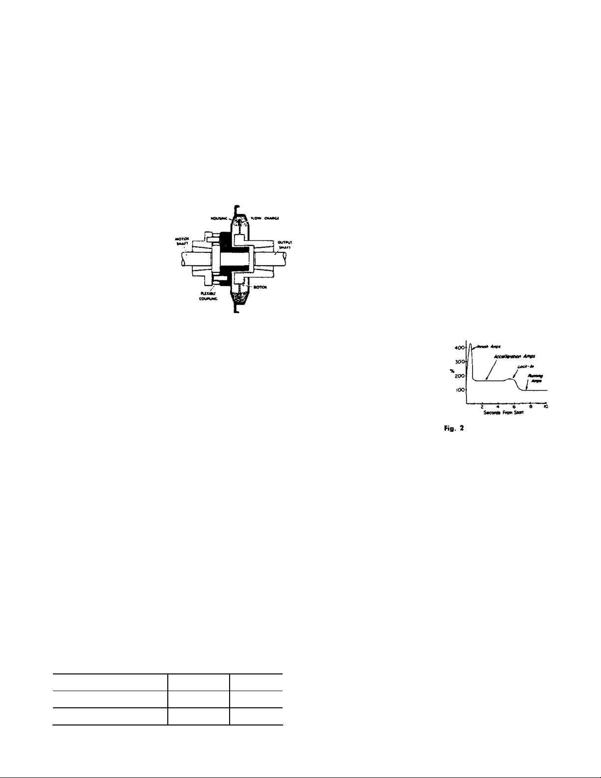
4. Push start button. Observe motor current during load
acceleration and number of seconds required to reach full
speed (Fig. 2).
Increase amount of flow charge if:
A. Acceleration time reaches maximum allowable
before load is up to speed. Turn off power
immediately if this time is reached.
B. Acceleration amperage is below motor nameplate.
Decrease amount of flow charge if:
A. Acceleration time is less than 1½ seconds.
B. Acceleration amperage is above 200% of motor
nameplate.
Caution: The rotor of the
FLEXIDYNE must slip during
acceleration to allow flow
charge to become evenly
distributed in the FLEXIDYNE
housing. Therefore, DO NOT
ALLOW FLEXIDYNE TO
RUN "FREE" (that is, without
a load on the driven end),
otherwise a dangerous outof-balance condition may
result.
The amount of flow charge in the FLEXIDYNE
determines the acceleration time for a given load. Longer
acceleration times will occur when less flow charge is
used and faster acceleration, from stop to full speed, will
be observed with greater amounts of flow charge.
OPERATION
The FLEXIDYNE should start the load smoothly and
without delay provided the proper amount of flow charge
has been used. Should the acceleration time exceed the
maximum allowable in Table 1, shut off power to the
FLEXIDYNE immediately. Allow the FLEXIDYNE to cool,
then add small amounts of flow charge until proper
acceleration is observed.
Vibration is an indication of accelerating too rapidly
and not allowing flow charge to become evenly distributed
in the FLEXIDYNE housing. This can be corrected by
removing small amounts of flow charge until vibration
subsides. Other causes of vibration are, undersize
shafting, unit not installed far enough on shaft, worn bore
in the unit, or mis-alignment.
Slippage – The FLEXIDYNE can, without slipping,
transmit overloads up to 130% of its present starting
torque. Should this breakaway torque be exceeded the
FLEXIDYNE will slip and generate heat (see Overload
Protection). Although slippage usually indicates increased
loads, it can also be caused by worn flow charge or a worn
rotor especially if the FLEXIDYNE has been in operation
for some time. The necessity to replace either a rotor or
flow charge will be made evident by a loss in power
transmitting capacity of the FLEXIDYNE.
Page 4

MAINTENANCE
For average industrial applications involving 3 or 4
starts a day of not more than 6 seconds acceleration time
each, the flow charge should be changed every 10,000
hours of operation. For more severe conditions, visually
inspect flow charge at more frequent intervals; it should be
changed when it has deteriorated to a half powder, half
granular condition. Visual inspections should continue until
enough flow charge changes have been made to
adequately establish a schedule for renewin g FLEXIDYNE
flow charge.
The FLEXIDYNE has been lubricated at the factory
and no further lubrication is required. Never apply grease,
oil or any other foreign material to the flow charge.
OVERLOAD PROTECTION
A Thermal Cutout is available from Dodge and is
recommended for FLEXIDYNE Size 9 where slippage
(due to overloads, starting or reversing) is frequent or
prolonged. Its function is to protect against excessive heat
which may be generated by the FLEXIDYNE, A Speed
Drop Cutout is available from Dodge for FLEXIDYNE Size
11 for installation where overloads or jamming may occur.
Either unit can be installed to send a signal to interrupt
the motor current and, if desired, activate a bell, light or
other warning device. Cutout switches are intended for
use in control circuits only and are not recommended for
dc current nor should they be used directly in the line to
the motor. Both units are available in special explosionproof models for hazardous atmospheres.
THERMAL CAPACITY
Since there is slippage within the flow charge during
acceleration, heat is generated from friction. The thermal
capacity of the FLEXIDYNE is based on balancing this
heat generated during acceleration against the cooling
time between accelerations. The amount of heat
generated is determined by the amount of horsepower
dissipated by slipping and the duration of each
acceleration. If the flow charge weight is light, the heat
generated will not be as great as that which would be
generated with a heavier flow charge, when compared at
the same acceleration time. A longer time between starts
will dissipate more heat; therefore, higher starting
horsepowers may be transmitted, or longer acceleration
times may be allowable. (See Starting Cycle)
Acceleration times shown in Table 1 are for starting
frequencies of one start per hour or less. If starting
frequency is more than once per hour, use acceleration
time for actual starting cycle shown in Table 2.
Acceleration times listed in Tables 1 & 2 are the
MAXIMUM permissible for the various starting frequencies
listed. The MINIMUM acceleration time required for proper
FLEXIDYNE operation is 1 to 1½ seconds. This is the time
required for the flow charge to be uniformly distributed
around the housing cavity before the unit "locks in". Any
acceleration time between the minimum and maximum
listed is acceptable, although a shorter acceleration time
will generally provide longer wear life. For applications
requiring a specific acceleration time (within these limits)
flow charge may be added or removed to produce the
required results.
Stalled – If a jam-up stalls the drive, the motor
continues to run and the FLEXIDYNE slips. This causes
heat to be generated at twice the rate of normal
acceleration. Therefore, the allowable slipping time, when
stalled, is half the allowable acceleration time given in
Table 1.
Starting Cycle is the time from the beginning of one
acceleration to the beginning of the next. Allowable
acceleration times in Table 2 are based on t he assumpti on
that the FLEXIDYNE will be running continuously except
for a momentary stop before the next start. If the stop is
more than momentary, decrease the actual starting cycle
by one-half the stopped time before using Table 2; far
example, with a 50 minute actual starting cycle of which
20 minutes is stopped time, decrease 50 by half of 20 to
give 40 minutes as the starting cycle time to use for Table
2.
Grouped Starts –For several starts grouped together
followed by uninterrupted running, add the acceleration
times of all starts and consider it as the time for one start.
The starting cycle would be the time from the beginning of
one group of starts to the beginning of the next group.
Table 1 – Flow Charge Recommendations
Based on % of Starting Torque for 1760 RPM NEMA Design B Motors
100% @ 1760 RPM 125% @ 1750 RPM 150% @ 1740 RPM 175% @ 1700 RPM 200% @ 1650 RPM
Rated
Motor
HP
15 9C 15.0 2 9 76 18.8 3 0 58 22.3 3 7 58 25.5 3 13 39 28.3 4 2 28
20 9C 20 3 2 52 25 3 10 40 30 4 0 26 34 4 8 22 38 5 3 16
25 11C 25 4 3 98 31 4 12 76 37 5 0 55 42 5 8 42 47 6 2 37
30 11C 30 4 10 80 37 5 0 55 45 5 12 39 51 6 3 33 57 6 12 27
40 11C 40 5 5 44 50 6 0 34 60 6 8 24 68 7 3 22 75 8 0 19
50 11C 50 5 13 34 62 6 10 24 74 7 6 20 85 8 2 17 94 8 11 15
FLEXI-
DYNE
Size
Start-
ing
HP
Flow
Charge
Lbs. Oz.
Max.
Time
In
Sec.
Start-
ing
HP
Flow
Charge
Lbs. Oz.
Max.
Time
In
Sec.
Start-
ing
HP
Flow
Charge
Lbs. Oz.
Max.
Time
In
Sec.
Start-
ing
HP
Flow
Charge
Lbs. Oz.
Max.
Time
In
Sec.
Start-
ing
HP
Flow
Charge
Lbs. Oz.
Max.
Time
Sec.
4
In
872-3
Page 5

Table 1 – Flow Charge Recommendations (cont.)
Based on % of Starting Torque for 1175 RPM NEMA Design B Motors
100% @ 1175 RPM 125% @ 1160 RPM 150% @ 1150 RPM 175% @ 1130 RPM 200% @ 1100 RPM
FLEXI-
DYNE
Size
Start-
ing
HP
Rated
Motor
HP
5 9C 5.0 2 4 230 6.2 2 11 212 7.4 3 1 193 8.5 3 8 176 9.4 3 12 161
7½ 9C 7.5 3 0 191 9.3 3 9 163 11.1 3 14 144 12.7 4 4 134 14.1 4 12 126
10 11C 10.0 5 0 480 12.4 5 5 439 14.8 5 10 398 17.0 6 3 360 19.0 7 0 325
15 11C 15.0 5 14 394 18.0 6 5 343 22.0 7 0 274 25.0 7 14 222 28.0 9 0 171
20 11C 20.0 6 8 308 25.0 7 14 222 30.0 8 4 136 34.0 8 13 125 38.0 9 10 113
Based on % of Starting Torque for 875 RPM NEMA Design B Motors
100% @ 875 RPM 125% @ 870 RPM 150% @ 850 RPM 175% @ 840 RPM 200% @ 820 RPM
Rated
FLEXI-
DYNE
Size
Start-
ing
HP
Motor
HP
2 9C 2.0 2 6 1000 2.5 2 2 1000 2.9 3 0 890 3.4 3 8 750 3.7 3 12 669
3 9C 3.0 3 0 862 3.7 3 8 669 4.4 4 0 475 5.0 4 6 310 5.6 4 14 297
5 11C 5.0 5 6 1000 6.2 5 14 904 7.3 6 10 816 8.4 7 0 728 9.4 7 8 648
7½ 11C 7.5 6 8 800 9.3 7 2 656 10.9 8 0 572 12.6 8 8 527 14.0 9 5 488
Table 2 – FLEXIDYNE Thermal Capacity
Start-
FLEXIDYN
E
ing
Size
HP
2.5 1000 .... .... 1000 .... .... 820 .... .... 600 .... .... 425 .... .... 225 .... .... 90 .... .... 45 .... ....
5.0 310 230 .... 310 230 .... 260 230 .... 180 190 .... 140 160 .... 70 100 .... 27 42 .... 13 22 ....
9.1 220 166 .... 220 166 .... 180 166 .... 130 135 .... 100 110 .... 50 72 .... 20 29 .... 10 15 ....
10.0 .... 150 135 .... 150 135 .... 150 135 .... 120 118 ....100 100 .... 65 70 .... 26 28 .... 13 14
15.0 .... 120 76 .... 120 76 .... 120 76 .... 100 66 .... 85 58 .... 50 38 .... 21 15 .... 11 7
9C
17.5 .... 110 64 .... 110 64 .... 110 64 .... 92 55 .... 78 48 .... 47 31 .... 19 12 .... 9 6
20 .... .... 52 .... .... 52 .... .... 52 .... .... 45 .... .... 38 .... .... 25 .... .... 10 .... .... 5
25 .... .... 40 .... .... 40 .... .... 40 .... .... 35 .... .... 30 .... .... 20 .... .... 8 .... .... 4
30 .... .... 26 .... .... 26 .... .... 26 .... .... 22 .... .... 18 .... .... 12 .... .... 5 .... .... ....
35 .... .... 21 .... .... 21 .... .... 21 .... .... 18 .... .... 15 .... .... 10 .... .... 4 .... .... ....
38 .... .... 16 .... .... 16 .... .... 16 .... .... 15 .... .... 13 .... .... 9 .... .... 3 .... .... ....
2 Hours 1 Hour 30 Min. 15 Min. 10 Min. 5 Min. 2 Min. 1 Min.
870 1160 1750 870 1160 1750 870 1160 1750 870 1160 1750 870 1160 1750 870 1160 1750 870 1160 1750 870 1160 1750
5 1000 .... .... 950 .... .... 700 .... .... 450 .... .... 290 .... .... 130 .... .... 46 .... .... 21 .... ....
10 600 480 .... 560 480 .... 440 400 .... 280 270 .... 180 200 .... 80 100 .... 30 40 .... 13 20 ....
20 320 308 116 300 308 116 230 257 116 150 175 96 90 130 80 42 65 50 15 26 21 6 13 11
30 .... 136 80 .... 136 80 .... 115 80 .... 80 67 .... 60 56 .... 30 35 .... 12 14 .... 6 7
40 .... 107 44 .... 107 44 .... 89 44 .... 63 37 .... 47 32 .... 23 20 .... 9 8 .... 4 4
50 .... 78 34 .... 78 34 .... 64 34 .... 46 28 .... 35 24 .... 17 15 .... 6 6 .... 3 3
11C
60 .... .... 24 .... .... 24 .... .... 24 .... .... 20 .... .... 17 .... .... 10 .... .... 4 .... .... ....
70 .... .... 21 .... .... 21 .... .... 21 .... .... 17 .... .... 14 .... .... 9 .... .... 3 .... .... ....
80 .... .... 18 .... .... 18 .... .... 18 .... .... 15 .... .... 12 .... .... 8 .... .... .... .... .... ....
90 .... .... 16 .... .... 16 .... .... 16 .... .... 13 .... .... 11 .... .... 7 .... .... .... .... .... ....
100 .... .... 14 .... .... 14 .... .... 14 .... .... 12 .... .... 10 .... .... 6 .... .... .... .... .... ....
2 Hours 1 Hour 30 Min. 15 Min. 10 Min. 5 Min. 2 Min. 1 Min.
870 1160 1750 870 1160 1750 870 1160 1750 870 1160 1750 870 1160 1750 870 1160 1750 870 1160 1750 870 1160 1750
Flow
Charge
Lbs. Oz.
Flow
Charge
Lbs. Oz.
Max.
Time
In
Sec.
Max.
Time
In
Sec.
Start-
ing
HP
Start-
ing
HP
Flow
Charge
Lbs. Oz.
Flow
Charge
Lbs. Oz.
Max.
Start-
Time
ing
In
HP
Sec.
Max.
Start-
Time
ing
In
HP
Sec.
Maximum Allowable Accelerat ion Time in Seconds for
Standard Motor Speeds at Vari ous Starting Cycles
Flow
Charge
Lbs. Oz.
Flow
Charge
Lbs. Oz.
Max.
Time
Sec.
Max.
Time
Sec.
Start-
ing
In
HP
Start-
ing
In
HP
Flow
Charge
Lbs. Oz.
Flow
Charge
Lbs. Oz.
Max.
Time
In
Sec.
Max.
Time
In
Sec.
Start-
ing
HP
Start-
ing
HP
Flow
Charge
Lbs. Oz.
Flow
Charge
Lbs. Oz.
Max.
Time
Sec.
Max.
Time
Sec.
In
In
REPLACEMENT OF PARTS
Disassembly:
1. Remove drive housing mechanism from driven shaft.
2. Remove filler plug and flow charge from FLEXIDYNE.
3. Remove housing screws and housing cover. Remove
cover seal retainer by inserting a small pin in holes for the
drive screws and tapping on. rod to remove drive screws.
Remove cover seal.
872-4
4. Remove screws that attach driven hub to rotor
retainer. Remove driven hub and rotor.
5. Remove bronze bushing retainer ring and slip bronze
bushing off drive housing.
6. Remove ball bearing snap ring and remove ball
bearing. To remove ball bearing, place 3 eq ual length pins
in the 3 holes thru the end of the drive housi ng and press
against the pins. For sizes 9 & 11 use 11/64” to 3/16”
diameter pins.
7. Remove rotor retainer and seal shield.
Page 6

Reassembly:
1. Install new seal felt and replace seal shield in drive
housing.
2. Install housing seal (red in color) on rotor retainer and
set rotor retainer in place in drive housing. Make certain
housing seal does not twist and that it is properly seated in
the drive housing.
3. Press ball bearings onto drive housing. Note: Press
against inner (not outer) race of bearing. Make certain
rotor retainer is not cocked when bearing enters it. Check
to see that rotor retainer rotates freely in housing seal.
4. Install ball bearing retaining ring.
5. Install rotor and driven hub. Install and tighten screws.
6. Install cover seal (gray in color) in housing cover. Li ne
up holes in cover seal retainer with holes in cover and
install drive screws.
7. Place cover in position on drive housing so that filler
plugs are diametricly opposed. Install and tighten housin g
screws.
8. Replace filler plug in housing cover. Tighten to
recommended torque of 200 in.-lbs.
Table 3. Manufacturer's Part Numbers for Replacement Bearings
FLEXIDYNE
Size
9C 399210 6011 2RS Z993L11
11C 399219 6014 2RS Z993L14
DODGE
Part Number
SKF
Part Number
NEW
DEPARTURE
Part Number
REPLACEMENT OF PARTS
Reference Name of Part
1
2 TAPER-LOCK Bushing with Screws ¡ 2 #2517 #2517
3
8
30 Drive Housing 1 391554 391559
31 Drive Housing Stud ‡ 309243 311243
HOUSING COVER and SEAL ASSEMBLY Ì 1 391457 391464
32 c Housing Cover 1 309080 311081
33 c Cover Seal (Gray Color) with Retainer and Drive Screws 1 391254 391255
35 Hex Nut 6 407083 407085
36 Housing Screw 6 411045 411063
37 Lockwasher 6 419009 419010
38 Filler Plug 2 308021 308021
39 Filler Plug Lockwasher 2 419121 419121
56 Rotor 1 309006 311006
58 Rotor Retainer 1 309207 311207
62 Rotor Retainer Screw 6 415056 415058
64 Housing Seal (Red Color) 1 309036 311038
70 Driven Hub 1 309205 311205
72 Ball Bearing † 1 391210 391219
76 Ball Bearing Snap Ring 1 421013 421019
80 Seal Felt 1 309024 311024
82 Seal Shield 1 309027 311027
84 Bronze Bushing 1 309212 311212
88 Bushing Retaining Ring 1 421009 421014
Standard Parts – used in Nos. 7 (9C) and 8 (11C) POLY-DISC Couplings. Use
Loctite #242 on threads when replacing coupling flange pins.
¡ When ordering TAPER-LOCK Bushings – specify size number and bare.
Ì Includes parts marked “#” listed immediately below.
Coupling Flange
Coupling POLY-DISC
Coupling Flange Pin
Type H
Type F
# The parts marked “#” make up the assemblies under which they are listed.
‡ 5 required for 9C; 6 required for 11C.
† See Table 3 – Manufacturer’s Part Numbers for Replacement Bearings.
Note: Order parts by the 6 digit part numbers – not the 2 digit reference numbers.
No.
Req’d.
1
1 008034 008035
‡ 409124 409125
9C Coupling 11C Coupling
Part Number Part Number
008045
008044
008047
008046
872-5
Page 7

FLEXIDYNE Trouble Analysis
Symptom Cause Cure
Vibration 1. Misalignment 1. Realign drive or coupling.
2. Bent shaft 2. Replace or straighten.
3. Excess flow charge 3. Remove small amount of flow charge.
4. Fused flow charge 4. Correct the overload.
5. Improper installation – Output shaft jammed
against housing
Erratic Acceleration 1. Breakdown of flow charge 1. Replace flow charge.
2. Caked flow charge 2. Moist environment – use stainless flow
5. Readjust spacing between shafts and
FLEXIDYNE.
charge.
FLEXIDYNE Doesn’t Slip 1. Improper installation – Output shaft jammed
against housing
2. Flow charge in bearings – causing bearing
seizure
Excessive Slippage 1. Not enough flow charge 1. Add flow charge.
2. Overload 2. Relieve overload.
3. Worn flow charge 3. Replace flow charge.
4. Worn rotor 4. Replace rotor.
Poor or short flow charge life 1. Excessive slip at start up 1. Add flow charge to reduce starting time.
2. Excessive inching or jogging of machine 2. Install time delay in motor control circuit.
1. Readjust spacing between shafts and
FLEXIDYNE.
2. Replace seals, bearings and flow charge
or replace FLEXIDYNE.
FLEXIDYNE Flow Charge Analysis
Condition Cause
1. Red oxide color, granular consistency 1. Normal after some usage.
2. Red oxide color, powdery consistency, possibly with
powdery flakes
3. Black, powdery 3. Rotor worn, excessive slip and heat.
4. Red oxide, powdery and chunky 4. Worn-out and moisture present.
5. Clumping of flow charge 5. Moisture present, use stainless flow
2. Worn-out, can cause FLEXIDYNE
damage.
charge.
 Loading...