


MODEL BE1004-06, BE1153, BE1209
WINDAGE SHOOTING REST
OWNER'S MANUAL
BE1005 Shown
COPYRIGHT © DECEMBER, 2011 BY GRIZZLY INDUSTRIAL, INC. REVISED JULY, 2018 (BL)
WARNING: NO PORTION OF THIS MANUAL MAY BE REPRODUCED IN ANY SHAPE OR FORM WITHOUT
PHONE: (570) 546-9663 • EMAIL: TECHSUPPORT@GRIZZLY.COM • #TR14645 • PRINTED IN TAIWAN
THE WRITTEN APPROVAL OF GRIZZLY INDUSTRIAL, INC.
Table of Contents
Controls & Terminology ................................................................................................................. 1
Introduction
Unpacking & Inventory
Initial Setup
Installing Bag
Setup & Use
Conversion for Left-Handed Shooters
Maintenance
Lubrication
BE1004 Parts Breakdown
BE1005 Parts Breakdown
BE1006 Parts Breakdown
BE1153 Parts Breakdown
BE1209 Parts Breakdown
BE1004 Specifications
BE1005 Specifications
..................................................................................................................................... 2
................................................................................................................... 2
...................................................................................................................................... 3
................................................................................................................................... 4
..................................................................................................................................... 5
................................................................................................................................... 10
..................................................................................................................................... 10
............................................................................................................. 11
............................................................................................................. 12
............................................................................................................. 13
............................................................................................................. 14
............................................................................................................. 15
.................................................................................................................. 16
.................................................................................................................. 17
.......................................................................................... 7
BE1006 Specifications
BE1153 Specifications
BE1209 Specifications
Optional Accessories
.................................................................................................................. 18
.................................................................................................................. 19
.................................................................................................................. 20
.................................................................................................................... 21
For your own safety, you
MUST read and understand
this manual before using
this product. After reading,
save this manual for later
reference. Download
the latest version from:
www.grizzly.com.
To avoid serious personal injury or death,
always follow the safety procedures supplied by the firearm manufacturer.

Controls & Terminology
Rear Foot
Knobs
Fore-End
Stop
Base
Quick Elevation
Knob
Clamp Shoe
Thumb Knobs
Windage
Adjustment
Knob
Front Foot
Knob
Foot Knob
Lock
BE1005 Shown
Mariner Wheel
(Fine Elevation)
Fine Elevation
Lock Handle
Quick
Elevation
Knob
FRONT
Windage Cradle
Windage Screw
REAR
Quick Elevation
Lock Handle
Windage Knob
Lock Nuts
BE1004-06, BE1153, BE1209
-1-
Introduction
Thank you for choosing a Bald Eagle Windage
Shooting Rest! Although each model has a few differences, they function the same and use identical
instructions for setup, operation, and maintenance.
Below are the main differences between the
three models:
BE1004
• Aluminum Triangle Base
• 3⁄8"-16 Foot Knobs
BE1005
• Aluminum Slingshot Base
• 3⁄8"-16 Foot Knobs
Unpacking &
Inventory
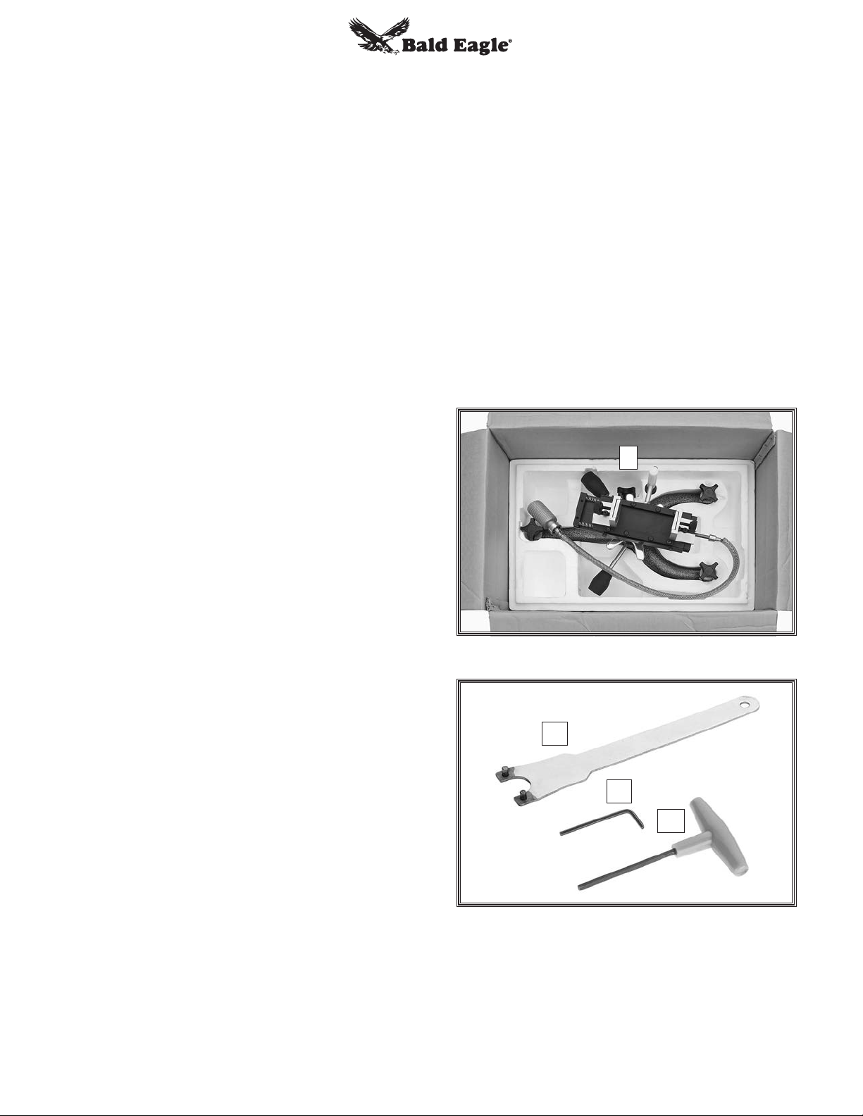
Your shooting rest was carefully packaged for
safe arrival. Please inspect all components as you
unpack them to ensure that they arrived in proper
condition.
If you find that any components are damaged,
please contact www.grizzly.com immediately.
Box Item Qty
A. Shooting Rest Assembly ............................ 1
Spanner Wrench ........................................ 1
B.
Hex Wrench 4mm ....................................... 1
C.
Hex T-Wrench 5mm ................................... 1
D.
BE1006
• Cast Iron Slingshot Base
• 1⁄2"-13 Foot Knobs
BE1153
• Cast Iron Triangle Base
• 1⁄2"-13 Foot Knobs
BE1209
• Cast Iron Triangle Base
• 5⁄8"-11 Foot Knobs
These shooting rests have been specially designed
to provide many years of trouble-free operation
through close attention to detail, ruggedly built
parts, and a rigid quality control program.
Please Note: The photos shown may not exactly
match your model because multiple models are
represented in this manual. However, the provided
procedures still apply.
A
Figure 1. Shooting rest assembly in box.
B
C
D
We stand behind our products! If you have questions about this product or its manual, please
contact us for assistance.
Contact Info
Bald Eagle, Inc.
P.O. Box 2069
Email: techsupport@grizzly.com
-2-
Bellingham, WA 98227-2069
Phone: (570) 546-9663
Figure 2. Included tools.
BE1004-06, BE1153, BE1209
Initial Setup
Your shooting rest is fully assembled but was
adjusted to fit in the box for shipping. Before using
it, you will need to make a few initial setup adjustments.
To make the initial setup adjustments:
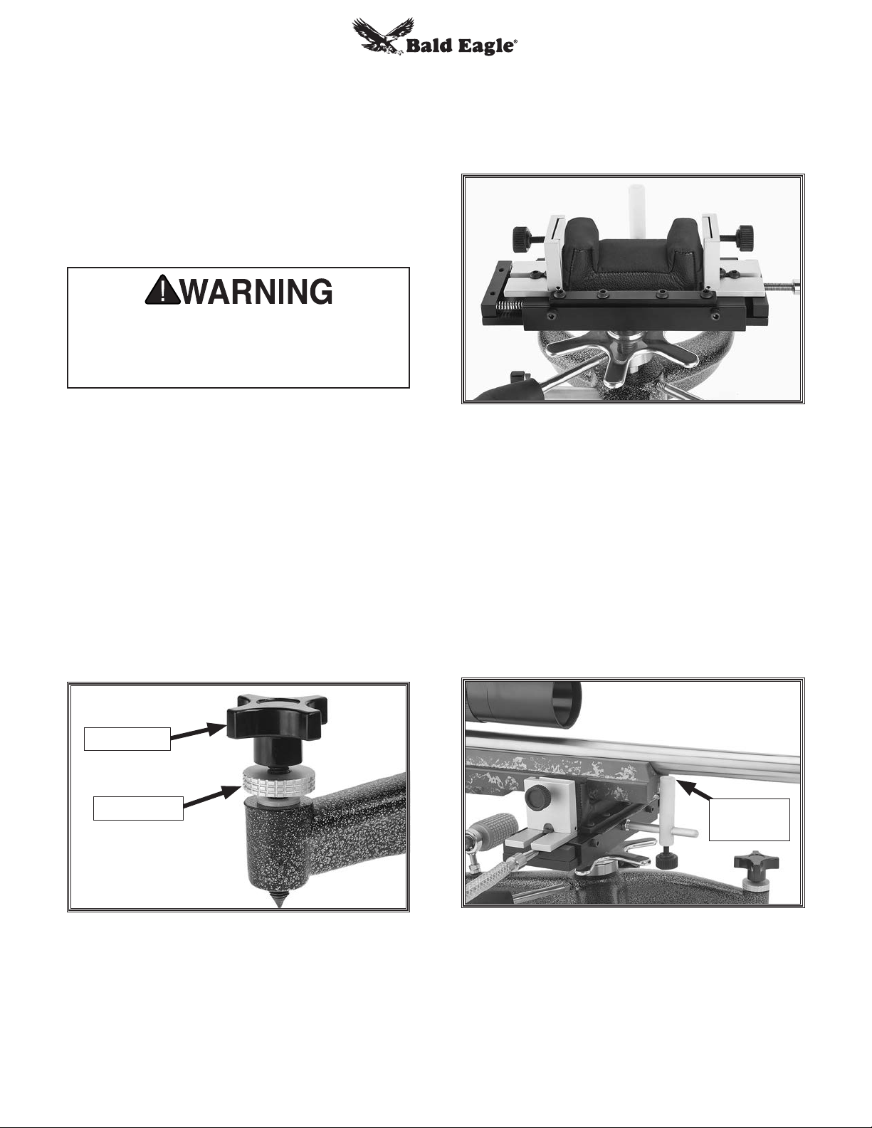
Loosen fine elevation lock and use mariner
1.
wheel to raise windage cradle approximately
1", as shown in Figure 3. This gives you
enough room to work during the next few
steps.
1" Minimum
Keyway
Shaft
Figure 5. Keyway aligned with fine elevation
lock knob shaft.
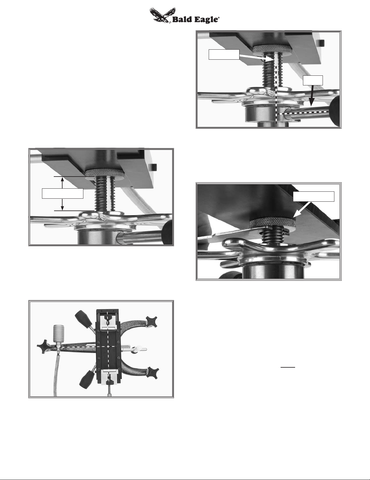
3. Using included spanner wrench, tighten
knurled nut against underside of base plate,
as shown in Figure 6.
Knurled Nut
Figure 3. Fine elevation raised up at least 1".
Position windage cradle perpendicular to
2.
base (see Figure 4). Align keyway with fine
elevation lock knob shaft, then tighten knob
(see Figure 5).
Figure 4. Windage cradle positioned
perpendicular to base.
Figure 6. Tightening knurled nut with spanner
wrench.
4. Check to make sure windage cradle is firmly
secured by trying to rotate it, by hand, with
light pressure.
The windage base plate should NOT move
independently of the fine elevation threads,
or it will shift when subjected to shooting
recoil. If you find that it does move, then retighten the knurled nut as shown in Figure 6.
Note: Besides the knurled nut, the windage
base plate is also secured from the top with
a bevel head screw (Part #15 on Page 8). If
it becomes necessary to tighten this screw
to properly secure the base plate, loosen the
knurled nut first.
BE1004-06, BE1153, BE1209
-3-
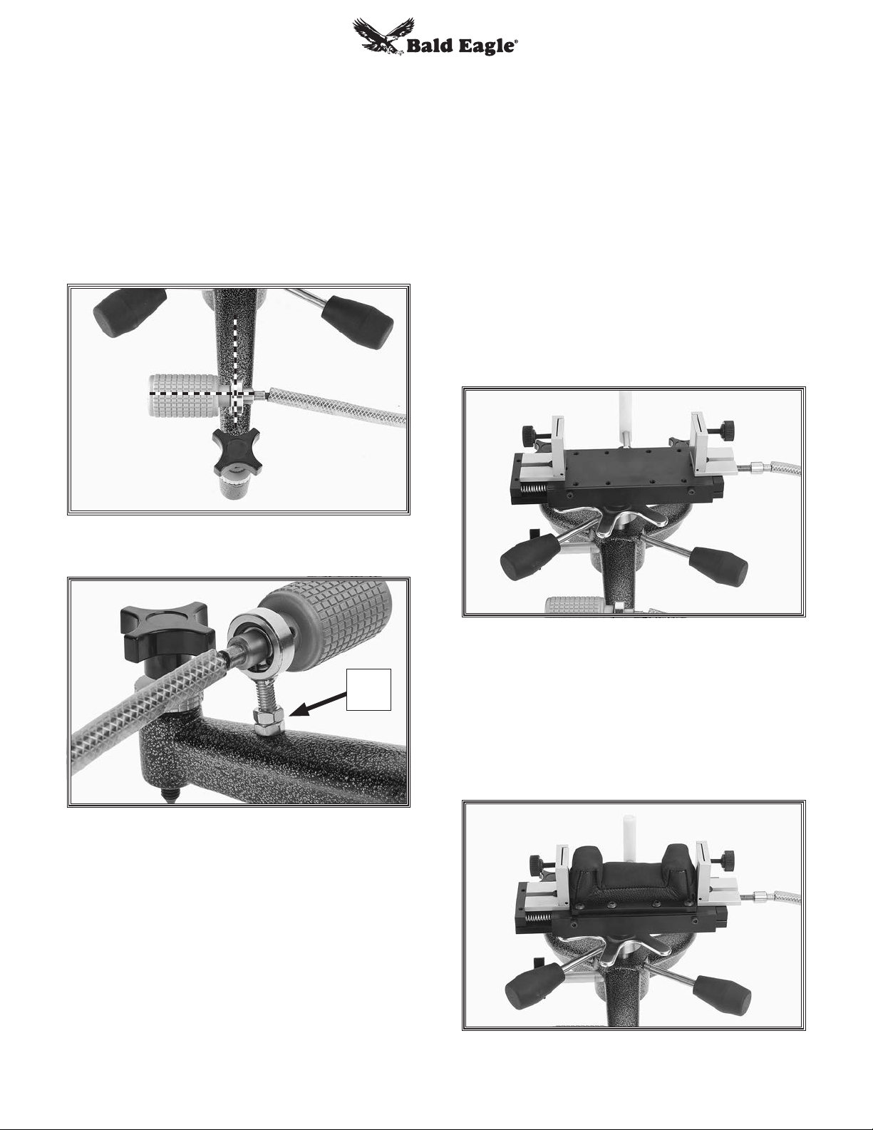
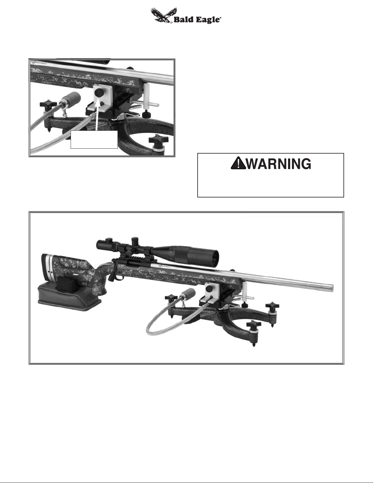
5. Position windage adjustment knob perpen-
dicular to base (see Figure 7). Using a
12mm wrench, tighten lower hex nut (Figure
8) against base, then tighten upper hex nut
against lower hex nut to lock it in place.
Note: For left-handed shooters, follow
Conversion for Left-Handed Shooters
instructions on Page 7 to position the windage control knob on the right side of the base.
After performing the conversion, return here.
Installing Bag
The windage cradle is designed to hold a front
bag with a 2" W x 4
ing flaps). Top quality bags are available from
www.grizzly.com (see back cover of manual for
details).
To install a front rest bag:
Make sure clamp shoes are adjusted straight
1.
up (not pivoted).
Remove (8) button head screws securing bag
2.
clamp bars, then remove clamp bars (see
Figure 9).
3
/4" L bottom base (not includ-
Figure 7. Windage adjustment knob
perpendicular to base.
Hex
Nuts
Figure 8. Hex nuts securing position of
windage adjustment knob.
Congratulations! You've completed the initial setup
of the shooting rest.
Before using the shooting rest, you will need to
install a front rest bag (not included), and then
make final adjustments at the shooting range with
your rifle properly positioned in the front rest bag.
Figure 9. Bag clamp bars removed.
Place bag on windage cradle and position
3.
it so tabs are between mounting holes for
clamp bar screws.
Re-install clamp bars and tighten button head
4.
screws to secure bag in place, as shown in
Figure 10.
-4-
Figure 10. Front rest bag installed.
BE1004-06, BE1153, BE1209
Setup & Use
These instructions tell you how to set up the rest
with your rifle and make adjustments while shooting at the range.
Before proceeding, make sure you have performed the previous initial setup and bag installation instructions.
Keep firearm UNLOADED until instructed.
Setting up rest with a loaded firearm may
increase risk of accidental discharge, which
could result in serious injury or death.
3. Adjust windage cradle by rotating windage
adjustment knob until cradle is centered in its
range of travel on slide. This ensures that you
will be able to move it in either direction once
you begin shooting.
To set up and use shooting rest:
Place shooting rest on a bench.
1.
Note: For F-Class or long-range shooting,
optional feet and long knobs are available
from Grizzly.com. See back cover of this
manual for model numbers and details.
Adjust base height as desired by rotating the
2.
three foot knobs. After setting base height,
tighten thumb nut (see Figure 11) to lock
knob and prevent unwanted movement while
shooting.
Foot Knob
Thumb Nut
Figure 12. Windage cradle adjusted to center
of slide.
. Place rear bag (not included) behind rest
4
(toward you).
. Insert butt of your unloaded rifle in rear bag,
5
and place fore-end of rifle on front rest bag
and against fore-end stop (the position of
fore-end stop can be adjusted as desired).
Note: The fore-end stop helps you return
your rifle to the exact same position after
each shot.
Fore-End
Stop
Figure 11. Foot adjustment controls.
BE1004-06, BE1153, BE1209
Figure 13. Fore-end stop positioned against
rifle.
-5-
6. Tighten clamp shoe thumb screws to squeeze
front rest bag against fore-end of rifle as
desired.
Clamp Shoe
Thumb Screw
Figure 14. Rifle secured in front bag.
8
. Adjust height of the front rest bag as neces-
sary using quick elevation knob. Once elevation is close to correct position, tighten quick
elevation lock knob.
9. Use mariner wheel to position exact elevation
of target. Snug (using light pressure only) the
fine elevation lock.
10. Use windage adjustment knob as necessary
to make final precise adjustments.
. Carefully load rifle and recheck sights. Make
11
additional fine adjustments to rest if necessary and tighten all knobs before shooting.
7. Position rest and rear bag as necessary to
align your rifle sights with target, making sure
fore-end of rifle remains against fore-end
stop.
To avoid serious personal injury or death,
always follow the safety procedures supplied by the firearm manufacturer.
Figure 15. Overview of an example rifle setup on the windage shooting rest (BE1005 shown).
-6-
BE1004-06, BE1153, BE1209

Conversion for
Left-Handed
Shooters
Out of the box, your shooting rest is set up
for right-handed shooters, meaning the windage
control knob is positioned to the left so it can be
adjusted with the shooter’s left hand—without
requiring the right hand to leave the gun.
Overview
The shooting rest can be converted for left-handed
shooters by removing the cradle slide and all the
components attached to it, drilling/tapping a new
hole in the opposite side of the cradle slide for the
fore-end stop post rail, and then re-installing with
the cradle assembly rotated 180° from the standard setup, the windage control knob positioned
to the right, and the stop post rail threaded into the
new hole (see Figures 16 and 17).
Drill & Tap a Hole Matching This One...
Using this same logic, left-handed shooters may
want to have the windage control knob mounted
to the right, as shown in Figure 16. The following
instructions explain how to perform the modification.
Stop Post Rail
Threaded into
New Hole
Cradle
Rotated
180°
Windage Knob
Facing Right
Figure 16. Shooting rest converted for left-
handed shooter.
Tools Needed for Drilling/Tapping Qty
• Drill Punch .................................................. 1
• Hammer ...................................................... 1
• Drill Press ................................................... 1
• Threading Tap 5⁄16 "-18 and Tap Handle ...... 1
• Drill Bit 17⁄64" (or size F) ............................... 1
• Cutting/Tapping Oil ..................... As Needed
• Vise ............................................................ 1
...on This Side
Cradle Slide
Middle Hole
Stop Post
Rail
11
16
13
12
Install #10 & #17 on
5
Opposite Sides with
10
19
17
Middle Hole Over New Hole
Figure 17. Overview of process for setting up
shooting rest for left-handed shooters.
Instructions
These instructions assume that the shooting rest
has been initially set up as described beginning
on Page 3. All part numbers referenced in the
following steps are from the parts breakdown
drawings in this manual. For clarity purposes,
we recommend referring to the parts breakdown
pages as you follow these steps.
BE1004-06, BE1153, BE1209
-7-
Follow these steps to convert shooting rest
18
8
18
8
for left-handed shooting:
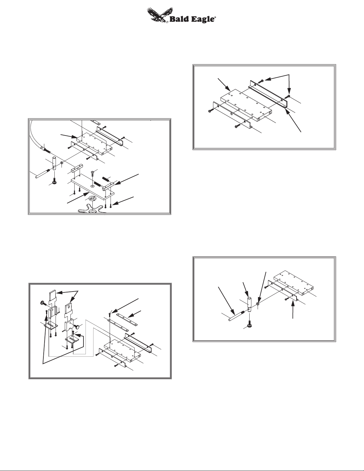
Remove cradle slide (#16) with its attached
1.
components from slide base (#14) by first
adjusting windage control knob to release
spring tension, then removing cap screws
that secure spring bracket (#22) to slide base
(#14), as shown in Figure 18. Once spring
bracket (#22) is removed, cradle slide (#16)
will easily slide off slide base (#14).
Cradle
Slide
9
9
12
12
13
13
5
5
Slide Base
20
20
14
14
23
23
43
43
15
15
10
10
21
16
16
22
19
19
17
17
Spring
Bracket
Cap
Screws
3.
Remove screws (#19) that secure fore slide
rail (#17) to cradle slide (#16), then separate
fore slide rail from cradle slide and set it
aside.
Cradle
Screws
Slide
19
17
16
10
Fore Slide
Rail
Figure 20. Separating fore slide rail from
cradle slide
Loosen hex nut (#13) that secures stop post
4.
rail (#11) against aft slide rail (#10), then
unthread and remove stop post rail (with the
attached stop post).
Figure 18. Removing cradle slide from slide
base.
2.
Remove screws (#6) that secure clamp shoe
assemblies to cradle slide (#16), then remove
screws (#18) that secure clamp bars (#8) to
cradle slide. Separate clamp shoe assemblies and clamp bars from cradle slide.
Clamp Shoe
Screws
Assemblies
2
3
3
Screws
2
4
4
5
6
6
7
7
18
18
8
8
10
10
Clamp
Bar
16
16
17
17
Figure 19. Removing clamp shoe and clamp
bar assemblies from cradle slide.
19
19
IMPORTANT: After removing stop post rail
(#11), pay special attention to threaded hole
from which it was removed. To complete this
conversion procedure, you will need to duplicate this hole on opposite side of cradle slide.
Stop
Post
Rail
11
11
Stop
Post
12
12
Hex Nut
13
13
10
10
16
16
Aft Slide
5
5
Rail
Figure 21. Location of hex nut that secures
stop post rail against aft slide rail.
-8-
BE1004-06, BE1153, BE1209
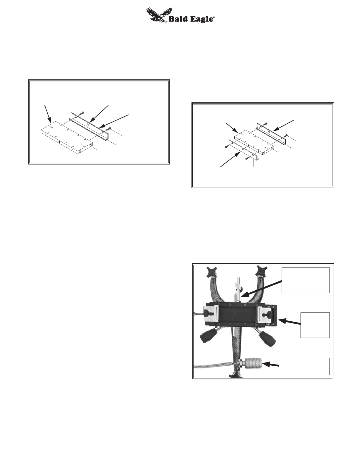
5. Remove aft slide rail (#10) and install it on
opposite side of cradle slide (#1), where fore
slide rail was originally positioned. In the next
step, you will use middle hole in aft slide rail
(#10) as a guide for marking drilling location
of new hole.
Cradle
Slide
Middle
Hole
Install aft slide rail (#10) over newly drilled
9.
hole on cradle slide, and install fore slide rail
(#17) on opposite side (see Figure 23).
TIP: Make sure that stop post rail (#11) is
able to thread into new hole before proceeding. If adjustments need to be made, it is
much easier to do so now—rather than after
full assembly.
Aft Slide
Rail
19
16
10
Figure 22. Aft side rail installed on opposite
side of cradle slide.
6.
Center tip of your drill punch in middle hole in
aft slide rail (#10) and lightly strike punch with
your hammer to make small indent in cradle
slide (brace shooting rest and cradle as necessary during this step, so you don't damage
any components). This indent will be your
starting point when you drill the new hole, so
take your time and make sure it is centered.
Remove aft slide rail before proceeding to
next step.
Use your 17⁄64" (or size F) drill bit in your drill
7.
press to drill a hole in location you marked in
previous step. The depth of newly drilled hole
should approximately match existing threaded hole on opposite side of cradle slide.
Secure cradle slide in vise, and use your 5⁄16"-
8.
18 threading tap with small amount of tapping/cutting oil to cut threads into new hole.
When finished threading, clean out hole and
clean up cradle slide.
Cradle
Slide
Fore Slide
17
16
Aft Rail
Slide
19
10
Rail
Figure 23. Aft and fore slide rails installed on
opposite sides.
10.
Re-assemble all remaining components in
reverse order of removal, but rotate cradle
180° from its original position and ensure
that windage control knob is positioned to
the right (see Figure 24), then tighten any
remaining fasteners.
Stop Post Rail
Threaded into
New Hole
Cradle
Rotated
180°
Windage Knob
Facing Right
BE1004-06, BE1153, BE1209
Figure 24. Example of shooting rest con-
verted for left-handed shooter.
-9-

Maintenance
Your shooting rest is constructed of high-quality
materials. With a small amount of care and regular maintenance, it will provide many years of reliable service.
For best results, always clean and dry the shooting rest after use. Do not allow moisture to remain
on unpainted steel parts, such as lock knob
shafts/threads, the quick elevation ram, or the fine
elevation threads.
To prevent corrosion from developing on unpainted steel surfaces, wipe them down with a light
coat of rifle oil.
2.
Lay shooting rest on its side. Using spray-
type lubricant, quickly spray fine elevation
threads and quick elevation ram. Turn shooting rest over and repeat this on other side.
Note: If using an oil can, apply 5-6 drops of
oil along each component, and use clean
brush to spread oil and coat surfaces.
Set shooting rest upright and completely
3.
lower fine and quick elevation.
Adjust windage knob to move windage cradle
4.
all the way to right.
Apply quick spray of oil (or 2 drops if using
5.
an oil can) to windage screw threads—just to
right of bracket (see Figure 26).
Lubrication
The fine elevation threads, windage screw threads,
and quick elevation ram will require a small
amount of lubrication on an "as needed" basis.
You can use your regular rifle oil for lubrication.
Since a small amount of oil may drip from the
shooting rest during this procedure, we recommend that it be performed over cardboard or
newspaper that can be discarded later.
To lubricate shooting rest components:
Raise fine and quick elevation to maximum
1.
height (see Figure 25).
Fine
Elevation
Threads
Apply
Oil Here
Bracket
Figure 26. Oil application area for windage
Adjust windage cradle all the way to the left
6.
and lubricate windage screw from left side of
bracket in same manner.
Adjust windage cradle back to center position.
7.
Wipe up any excess oil from shooting rest.
8.
The lubrication procedure is complete.
Windage Screw
screw.
Quick
Elevation
Ram
Figure 25. Oil application areas for fine and
quick elevation components.
-10-
BE1004-06, BE1153, BE1209

3
11
42
27
BE1004 Parts Breakdown
1
REF PART # DESCRIPTION
1 PBE1004001 CLAMP SHOE
2 PBE1004002 ROLL PIN 3 X 50
3 PBE1004003 ADJUSTING PLATE
4 PBE1004004 CLAMP SUPPORT
5 PBE1004005 THUMB KNOB 1/4-28 X 1-1/4
6 PBE1004006 BUTTON HD CAP SCR 1/4-20 X 1/2
7 PBE1004007 FLAT HD SCR 10-24 X 1/2
8 PBE1004008 CLAMP BAR
9 PBE1004009 DRIVE SHAFT
10 PBE1004010 AFT SLIDE RAIL
11 PBE1004011 STOP POST RAIL
12 PBE1004012 STOP POST
13 PBE1004013 HEX NUT 5/16-18
14 PBE1004014 SLIDE BASE
15 PBE1004015 FLAT HD CAP SCR 3/8-16 X 3/4
16 PBE1004016 SLIDE
17 PBE1004017 FORE SLIDE RAIL
18 PBE1004018 BUTTON HD CAP SCR 1/4-20 X 1/2
19 PBE1004019 BUTTON HD CAP SCR 10-24 X 1/2
20 PBE1004020 SLIDE ADJUST BRACKET
21 PBE1004021 COMPRESSION SPRING
22 PBE1004022 SPRING BRACKET
23 PBE1004023 BUTTON HD CAP SCR 10-24 X 1/2
24 PBE1004024 MARINER WHEEL
25 PBE1004025 ELEVATION SCREW 3/4-10
26 PBE1004026 THRUST BEARING TEFLON
27 PBE1004027 LOCK KNOB 3/8-16
28 PBE1004028 ELEVATION KNOB & PINION ASSY
29 PBE1004029 KEY 1/4 X 1/4 X 1-3/4
30 PBE1004030 ELEVATION RACK
31 PBE1004031 SET SCREW 1/4-20 X 1/2 BALL-PT
32 PBE1004032 FLAT WASHER 3/8 TEFLON
41
33 PBE1004033 KNOB BEARING
34 PBE1004034 SET SCREW 10-24 X 1/4
35 PBE1004035 LEVELING SCREW 3/8-16 X 3-1/2
36 PBE1004036 LOCKING THUMB WHEEL 3/8-16
37 PBE1004037 TRIANGLE BASE, ALUMINUM
39 PBE1004039 HEX NUT 5/16-18
40 PBE1004040 FLAT WASHER 5/16 TEFLON
41 PBE1004041 SLIDE KNOB
42 PBE1004042 SPANNER WRENCH 28MM PIN-TYPE
43 PBE1004043 KNURLED SPANNER NUT 3/4-10
44 PBE1004044 HEX WRENCH 4MM
45 PBE1004045 HEX T-WRENCH 5MM
12
36
32
2
9
35
4
44
5
45
6
7
18
8
19
17
16
10
13
20
5
14
23
43
15
21
22
24
27
25
34
26
33
39
30
40
39
29
31
37
28
19
BE1004-06, BE1153, BE1209
-11-

BE1005 Parts Breakdown
1
3
11
42
27
12
2
9
36
7
35
32
REF PART # DESCRIPTION
1 PBE1005001 CLAMP SHOE
4
44
5
45
6
18
8
19
17
16
10
13
20
5
14
23
43
15
21
22
24
27
25
34
26
33
39
30
40
39
29
31
37
28
19
2 PBE1005002 ROLL PIN 3 X 50
3 PBE1005003 ADJUSTING PLATE
4 PBE1005004 CLAMP SUPPORT
5 PBE1005005 THUMB KNOB 1/4-28 X 1-1/4
6 PBE1005006 BUTTON HD CAP SCR 1/4-20 X 1/2
7 PBE1005007 FLAT HD SCR 10-24 X 1/2
8 PBE1005008 CLAMP BAR
9 PBE1005009 DRIVE SHAFT
10 PBE1005010 AFT SLIDE RAIL
11 PBE1005011 STOP POST RAIL
12 PBE1005012 STOP POST
13 PBE1005013 HEX NUT 5/16-18
14 PBE1005014 SLIDE BASE
15 PBE1005015 FLAT HD CAP SCR 3/8-16 X 3/4
16 PBE1005016 SLIDE
17 PBE1005017 FORE SLIDE RAIL
18 PBE1005018 BUTTON HD CAP SCR 1/4-20 X 1/2
19 PBE1005019 BUTTON HD CAP SCR 10-24 X 1/2
20 PBE1005020 SLIDE ADJUST BRACKET
21 PBE1005021 COMPRESSION SPRING
22 PBE1005022 SPRING BRACKET
23 PBE1005023 BUTTON HD CAP SCR 10-24 X 1/2
24 PBE1005024 MARINER WHEEL
25 PBE1005025 ELEVATION SCREW 3/4-10
26 PBE1005026 THRUST BEARING TEFLON
27 PBE1005027 LOCK KNOB 3/8-16
28 PBE1005028 ELEVATION KNOB & PINION ASSY
29 PBE1005029 KEY 1/4 X 1/4 X 1-3/4
30 PBE1005030 ELEVATION RACK
31 PBE1005031 SET SCREW 1/4-20 X 1/2 BALL-PT
41
32 PBE1005032 FLAT WASHER 3/8 TEFLON
33 PBE1005033 KNOB BEARING
34 PBE1005034 SET SCREW 10-24 X 1/4
35 PBE1005035 LEVELING SCREW 3/8-16 X 3-1/2
36 PBE1005036 LOCKING THUMB WHEEL 3/8-16
37 PBE1005037 SLINGSHOT BASE, ALUMINUM
39 PBE1005039 HEX NUT 5/16-18
40 PBE1005040 FLAT WASHER 5/16 TEFLON
41 PBE1005041 SLIDE KNOB
42 PBE1005042 SPANNER WRENCH 28MM PIN-TYPE
43 PBE1005043 KNURLED SPANNER NUT 3/4-10
44 PBE1005044 HEX WRENCH 4MM
45 PBE1005045 HEX T-WRENCH 5MM
-12-
BE1004-06, BE1153, BE1209

BE1006 Parts Breakdown
1
3
11
42
27
12
2
9
36
7
35
32
REF PART # DESCRIPTION
4
44
5
45
6
18
8
19
17
16
10
13
20
5
14
23
43
15
21
22
24
27
25
34
26
33
39
30
40
39
29
31
37
28
19
1 PBE1006001 CLAMP SHOE
2 PBE1006002 ROLL PIN 3 X 50
3 PBE1006003 ADJUSTING PLATE
4 PBE1006004 CLAMP SUPPORT
5 PBE1006005 THUMB KNOB 1/4-28 X 1-1/4
6 PBE1006006 BUTTON HD CAP SCR 1/4-20 X 1/2
7 PBE1006007 FLAT HD SCR 10-24 X 1/2
8 PBE1006008 CLAMP BAR
9 PBE1006009 DRIVE SHAFT
10 PBE1006010 AFT SLIDE RAIL
11 PBE1006011 STOP POST RAIL
12 PBE1006012 STOP POST
13 PBE1006013 HEX NUT 5/16-18
14 PBE1006014 SLIDE BASE
15 PBE1006015 FLAT HD CAP SCR 3/8-16 X 3/4
16 PBE1006016 SLIDE
17 PBE1006017 FORE SLIDE RAIL
18 PBE1006018 BUTTON HD CAP SCR 1/4-20 X 1/2
19 PBE1006019 BUTTON HD CAP SCR 10-24 X 1/2
20 PBE1006020 SLIDE ADJUST BRACKET
21 PBE1006021 COMPRESSION SPRING
22 PBE1006022 SPRING BRACKET
23 PBE1006023 BUTTON HD CAP SCR 10-24 X 1/2
24 PBE1006024 MARINER WHEEL
25 PBE1006025 ELEVATION SCREW 3/4-10
26 PBE1006026 THRUST BEARING TEFLON
27 PBE1006027 LOCK KNOB 3/8-16
28 PBE1006028 ELEVATION KNOB & PINION ASSY
29 PBE1006029 KEY 1/4 X 1/4 X 1-3/4
30 PBE1006030 ELEVATION RACK
31 PBE1006031 SET SCREW 1/4-20 X 1/2 BALL-PT
41
32 PBE1006032 FLAT WASHER 1/2 TEFLON
33 PBE1006033 KNOB BEARING
34 PBE1006034 SET SCREW 10-24 X 1/4
35 PBE1006035 LEVELING SCREW 1/2-13 X 3-1/2
36 PBE1006036 LOCKING THUMB WHEEL 1/2-13
37 PBE1006037 SLINGSHOT BASE, CAST IRON
39 PBE1006039 HEX NUT 5/16-18
40 PBE1006040 FLAT WASHER 5/16 TEFLON
41 PBE1006041 SLIDE KNOB
42 PBE1006042 SPANNER WRENCH 28MM PIN-TYPE
43 PBE1006043 KNURLED SPANNER NUT 3/4-10
44 PBE1006044 HEX WRENCH 4MM
45 PBE1006045 HEX T-WRENCH 5MM
BE1004-06, BE1153, BE1209
-13-

BE1153 Parts Breakdown
1
2
4
3
6
44
5
45
7
18
8
9
19
17
11
42
27
12
13
15
20
5
14
23
43
24
10
21
16
22
27
25
33
39
39
40
41
36
32
35
26
30
29
31
37
28
19
REF PART # DESCRIPTION
1 PBE1153001 CLAMP SHOE
2 PBE1153002 ROLL PIN 3 X 50
3 PBE1153003 ADJUSTING PLATE
4 PBE1153004 CLAMP SUPPORT
5 PBE1153005 THUMB KNOB 1/4-28 X 1-1/4
6 PBE1153006 BUTTON HD CAP SCR 1/4-20 X 1/2
7 PBE1153007 FLAT HD SCR 10-24 X 1/2
8 PBE1153008 CLAMP BAR
9 PBE1153009 DRIVE SHAFT
10 PBE1153010 AFT SLIDE RAIL
11 PBE1153011 STOP POST RAIL
12 PBE1153012 STOP POST
13 PBE1153013 HEX NUT 5/16-18
14 PBE1153014 SLIDE BASE
15 PBE1153015 FLAT HD CAP SCR 3/8-16 X 3/4
16 PBE1153016 SLIDE
17 PBE1153017 FORE SLIDE RAIL
18 PBE1153018 BUTTON HD CAP SCR 1/4-20 X 3/4
19 PBE1153019 BUTTON HD CAP SCR 10-24 X 1/2
20 PBE1153020 SLIDE ADJUST BRACKET
21 PBE1153021 COMPRESSION SPRING
22 PBE1153022 SPRING BRACKET
23 PBE1153023 BUTTON HD CAP SCR 10-24 X 1/2
24 PBE1153024 MARINER WHEEL
25 PBE1153025 ELEVATION SCREW 3/4-10
26 PBE1153026 THRUST BEARING TEFLON
27 PBE1153027 LOCK KNOB 3/8-16
28 PBE1153028 ELEVATION KNOB & PINION ASSY
34
29 PBE1153029 KEY 1/4 X 1/4 X 1-3/4
30 PBE1153030 ELEVATION RACK
31 PBE1153031 SET SCREW 1/4-20 X 1/2 BALL-PT
32 PBE1153032 FLAT WASHER 1/2 TEFLON
33 PBE1153033 KNOB BEARING
34 PBE1153034 SET SCREW 10-24 X 1/4
35 PBE1153035 LEVELING SCREW 1/2-13 x 3-1/2
36 PBE1153036 LOCKING THUMB WHEEL 1/2-13
37 PBE1153037 TRIANGLE BASE (CAST-IRON)
39 PBE1153039 HEX NUT 5/16-18
40 PBE1153040 FLAT WASHER 5/16 TEFLON
41 PBE1153041 SLIDE KNOB
42 PBE1153042 SPANNER WRENCH 28MM PIN-TYPE
43 PBE1153043 KNURLED SPANNER NUT 3/4-10
44 PBE1153044 HEX WRENCH 4MM
45 PBE1153045 HEX T-WRENCH 5MM
-14-
BE1004-06, BE1153, BE1209

3
11
42
27
BE1209 Parts Breakdown
1
REF PART # DESCRIPTION
12
36
32
2
9
35
4
44
5
45
6
7
18
8
19
17
16
10
13
20
5
14
23
43
15
21
22
24
27
25
34
26
33
39
30
40
39
29
31
37
28
19
1 PBE1209001 CLAMP SHOE
2 PBE1209002 ROLL PIN 3 X 50
3 PBE1209003 ADJUSTING PLATE
4 PBE1209004 CLAMP SUPPORT
5 PBE1209005 THUMB KNOB 1/4-28 X 1-1/4
6 PBE1209006 BUTTON HD CAP SCR 1/4-20 X 1/2
7 PBE1209007 FLAT HD SCR 10-24 X 1/2
8 PBE1209008 CLAMP BAR
9 PBE1209009 DRIVE SHAFT
10 PBE1209010 AFT SLIDE RAIL
11 PBE1209011 STOP POST RAIL
12 PBE1209012 STOP POST
13 PBE1209013 HEX NUT 5/16-18
14 PBE1209014 SLIDE BASE
15 PBE1209015 FLAT HD CAP SCR 3/8-16 X 3/4
16 PBE1209016 WINDAGE SLIDE
17 PBE1209017 FORE SLIDE RAIL
18 PBE1209018 BUTTON HD CAP SCR 1/4-20 X 1/2
19 PBE1209019 BUTTON HD CAP SCR 10-24 X 1/2
20 PBE1209020 SLIDE ADJUST BRACKET
21 PBE1209021 COMPRESSION SPRING
22 PBE1209022 SPRING BRACKET
23 PBE1209023 BUTTON HD CAP SCR 10-24 X 1/2
24 PBE1209024 MARINER WHEEL
25 PBE1209025 ELEVATION SCREW 3/4-10
26 PBE1209026 THRUST BEARING TEFLON
27 PBE1209027 LOCK KNOB 3/8-16
28 PBE1209028 ELEVATION KNOB & PINION ASSY
29 PBE1209029 KEY 1/4 X 1/4 X 1-3/4
30 PBE1209030 ELEVATION RACK
31 PBE1209031 SET SCREW 1/4-20 X 1/2 BALL-PT
41
32 PBE1209032 FLAT WASHER 5/8 TEFLON
33 PBE1209033 KNOB BEARING
34 PBE1209034 SET SCREW 10-24 X 1/4
35 PBE1209035 LEVELING SCREW 5/8-11 X 3-1/2
36 PBE1209036 LOCKING THUMB WHEEL 5/8-11
37 PBE1209037 BIG FIFTY BASE, CAST IRON
39 PBE1209039 HEX NUT 5/16-18
40 PBE1209040 FLAT WASHER 5/16 TEFLON
41 PBE1209041 SLIDE KNOB
42 PBE1209042 SPANNER WRENCH 28MM PIN-TYPE
43 PBE1209043 KNURLED SPANNER NUT 3/4-10
44 PBE1209044 HEX WRENCH 4MM
45 PBE1209045 HEX T-WRENCH 5MM
BE1004-06, BE1153, BE1209
-15-

BE1004
Triangle Windage Shooting Rest
Product Dimensions
Weight .......................................................................................................................................... 12 lbs.
Overall Length (Front-to-Back) ..........................................................................................................14"
Overall Width (Side-to-Side) ...........................................................................................................19
Overall Height ...................................................................................................................... 7
Footprint (Pin-to-Pin).........................................................................................................12
Shipping Dimensions
Weight .......................................................................................................................................... 17 lbs.
Box Size (L x W x H) ...................................................................................................... 21" x 19" x 10"
Windage Information
1
⁄4" – 11 7⁄8"
3
⁄4" Triangle
1
⁄2"
Cradle Depth (Inside of Bag Straps)....................................................................................................2"
Maximum Front Bag Width ...............................................................................................................4
Minimum Bench-to-Cradle Base Height ...........................................................................................5
Maximum Bench-to-Cradle Base Height ..........................................................................................9
Horizontal Movement (Side-to-Side) .................................................................................................
Quick Elevation Travel (Primary Rise) ..............................................................................................1
Fine Elevation Travel (Secondary Rise) ........................................................................................ 1
Feet Elevation Travel (Base Rise) ......................................................................................................
Fore-End Stop Height (from Cradle Base) .......................................................................................1
Fore-End Stop Travel ........................................................................................................................2
Thread Size of Base Foot Knobs...................................................................................................
Construction Materials
Base ........................................................................................................................................ Aluminum
Windage Cradle ......................................................................................................... Aluminum & Steel
Fore-End Stop................................................................................High Density Poly-Ethylene (HDPE)
Other
Country of Origin ..........................................................................................................................Taiwan
BE1004 Specifications
13
13
3
⁄8"-16
3
⁄4"
1
⁄4"
1
⁄2"
⁄16"
7
⁄8"
⁄16"
3
⁄4"
7
⁄8"
1
⁄4"
-16-
BE1004-06, BE1153, BE1209

Slingshot Windage Shooting Rest
Product Dimensions
BE1005
Weight .......................................................................................................................................... 12 lbs.
Overall Length (Front-to-Back) .......................................................................................................16
Overall Width (Side-to-Side) ...........................................................................................................17
Overall Height ...................................................................................................................... 7
1
Footprint (Pin-to-Pin).....................................................................................................7
⁄4" W x 15 1⁄2" L
Shipping Dimensions
Weight .......................................................................................................................................... 17 lbs.
Box Size (L x W x H) .......................................................................................................22" x 15" x 11"
Windage Information
Cradle Depth (Inside of Bag Straps)....................................................................................................2"
Maximum Front Bag Width ...............................................................................................................4
Minimum Bench-to-Cradle Base Height ...........................................................................................5
Maximum Bench-to-Cradle Base Height ..........................................................................................9
Horizontal Movement (Side-to-Side) .................................................................................................
Quick Elevation Travel (Primary Rise) ..............................................................................................1
Fine Elevation Travel (Secondary Rise) ........................................................................................ 1
Feet Elevation Travel (Base Rise) ......................................................................................................
Fore-End Stop Height (from Cradle Base) .......................................................................................1
Fore-End Stop Travel ........................................................................................................................2
Thread Size of Base Foot Knobs...................................................................................................
1
⁄4" – 11 7⁄8"
13
13
3
⁄8"-16
1
⁄2"
1
⁄4"
3
⁄4"
1
⁄4"
1
⁄2"
⁄16"
7
⁄8"
⁄16"
3
⁄4"
7
⁄8"
1
⁄4"
Construction Materials
Base ........................................................................................................................................ Aluminum
Windage Cradle ......................................................................................................... Aluminum & Steel
Fore-End Stop................................................................................High Density Poly-Ethylene (HDPE)
Other
Country of Origin ..........................................................................................................................Taiwan
BE1005 Specifications
BE1004-06, BE1153, BE1209
-17-

Slingshot Windage Shooting Rest
Product Dimensions
BE1006 Heavy-Duty
Weight .......................................................................................................................................... 21 lbs.
Overall Length (Front-to-Back) .......................................................................................................16
Overall Width (Side-to-Side) ...........................................................................................................17
Overall Height ...................................................................................................................... 7
5
Footprint (Pin-to-Pin)................................................................................................. 7
⁄16" W x 15 19⁄32" L
Shipping Dimensions
Weight .......................................................................................................................................... 26 lbs.
Box Size (L x W x H) .......................................................................................................22" x 15" x 11"
Windage Information
Cradle Depth (Inside of Bag Straps)....................................................................................................2"
Maximum Front Bag Width ...............................................................................................................4
Minimum Bench-to-Cradle Base Height ...........................................................................................5
Maximum Bench-to-Cradle Base Height ..........................................................................................9
Horizontal Movement (Side-to-Side) .................................................................................................
Quick Elevation Travel (Primary Rise) ..............................................................................................1
Fine Elevation Travel (Secondary Rise) ........................................................................................ 1
Feet Elevation Travel (Base Rise) ......................................................................................................
Fore-End Stop Height (from Cradle Base) .......................................................................................1
Fore-End Stop Travel ........................................................................................................................2
Thread Size of Base Foot Knobs...................................................................................................
1
⁄4" – 11 7⁄8"
13
13
1
⁄2"-13
1
⁄2"
1
⁄4"
3
⁄4"
1
⁄4"
1
⁄2"
⁄16"
7
⁄8"
⁄16"
3
⁄4"
7
⁄8"
1
⁄4"
Construction Materials
Base ......................................................................................................................................... Cast Iron
Windage Cradle ......................................................................................................... Aluminum & Steel
Fore-End Stop................................................................................High Density Poly-Ethylene (HDPE)
Other
Country of Origin ..........................................................................................................................Taiwan
BE1006 Specifications
-18-
BE1004-06, BE1153, BE1209

BE1153
Taiwan
Triangle Windage Shooting Rest
Product Dimensions
Weight ....................................................................................................................................... 18.3 lbs.
Overall Length (Front-to-Back) ..........................................................................................................14"
Overall Width (Side-to-Side) ...........................................................................................................19
Overall Height ...................................................................................................................... 7
Footprint (Pin-to-Pin).........................................................................................................12
Shipping Dimensions
Weight .......................................................................................................................................... 23 lbs.
Box Size (L x W x H) ...................................................................................................... 21" x 19" x 10"
Windage Information
1
⁄4" – 11 7⁄8"
3
⁄4" Triangle
1
⁄2"
Cradle Depth (Inside of Bag Straps)....................................................................................................2"
Maximum Front Bag Width ...............................................................................................................5
Minimum Bench-to-Cradle Base Height ...........................................................................................5
Maximum Bench-to-Cradle Base Height ..........................................................................................8
Horizontal Movement (Side-to-Side) .................................................................................................
Quick Elevation Travel (Primary Rise) ..............................................................................................1
Fine Elevation Travel (Secondary Rise) ........................................................................................ 1
Feet Elevation Travel (Base Rise) ......................................................................................................
Fore-End Stop Height (from Cradle Base) .......................................................................................1
Fore-End Stop Travel ........................................................................................................................2
Thread Size of Base Foot Knobs...................................................................................................
Construction Materials
Base ......................................................................................................................................... Cast Iron
Windage Cradle ......................................................................................................... Aluminum & Steel
Fore-End Stop................................................................................High Density Poly-Ethylene (HDPE)
Other
Country of Origin ..........................................................................................................................
13
13
1
⁄2"-13
1
⁄2"
1
⁄4"
5
⁄8"
⁄16"
7
⁄8"
⁄16"
3
⁄4"
7
⁄8"
1
⁄4"
BE1004-06, BE1153, BE1209
-19-

BE1209
Big Fifty Rest w/Windage — Cast Iron
Product Dimensions
Weight .......................................................................................................................................... 27 lbs.
Overall Length (Front-to-Back) ..........................................................................................................18"
Overall Width (Side-to-Side) ..............................................................................................................20"
Overall Height .............................................................................................................................7" – 11"
Footprint (Pin-to-Pin)......................................................................................................... 18
Shipping Dimensions
Weight .......................................................................................................................................... 33 lbs.
Box Size (L x W x H) .......................................................................................................24" x 22" x 11"
Important Specifications
7
⁄8" Triangle
Cradle Depth (Inside of Bag Hold Down Straps) .............................................................................. 21⁄2"
Maximum Front Bag Width ...............................................................................................................8
Minimum Bench-to-Cradle Base Height ..............................................................................................5 "
Maximum Bench-to-Cradle Base Height ..........................................................................................8
Horizontal Movement (Side-to-Side) .................................................................................................
Quick Elevation Travel (Primary Rise) ..............................................................................................1
Fine Elevation Travel (Secondary Rise) ..............................................................................................2"
Feet Elevation Travel (Base Rise) ......................................................................................................
Fore-End Stop Height (from Cradle Base) .......................................................................................2
Fore-End Stop Travel ........................................................................................................................2
Thread Size of Base Foot Knobs...................................................................................................
Construction Materials
Base ......................................................................................................................................... Cast Iron
Cradle ........................................................................................................................ Aluminum & Steel
Fore-End Stop................................................................................High Density Poly-Ethylene (HDPE)
Other
Country of Origin ..........................................................................................................................Taiwan
13
5
⁄8"-11
1
⁄4"
3
⁄4"
⁄16"
7
⁄8"
3
⁄4"
1
⁄8"
3
⁄8"
-20-
BE1209 Specifications
BE1004 Specifications
BE1004-06, BE1153, BE1209

Optional Accessories
In addition to the products shown below, top quality bags are available from www.grizzly.com.
BE1007—3PK F-CLASS FEET (SB) BE1004-5
BE1007SS—3PK F-CLASS FEET (SS) BE1004- 5
BE1120—3PK F-CLASS FEET (SB) BE1006-53
BE1213— 3PK F-CLASS FEET (SB) BE1209
Available in satin black steel (SB) or polished
stainless steel (SS), these optional feet install
on Bald Eagle windage shooting rests for better
support when positioning the rest in soft, uneven
areas or soggy soil. Dimensions: 3" diameter,
5
⁄8" height, 3⁄8"-16 threaded holes on BE1007/
1
BE1007SS,
5
⁄8"-11 threaded holes on BE1209.
1
⁄2"-13 threaded holes on BE1120, and
BALD EAGLE FRONT BAGS
These top-quality front bags are constructed with
genuine leather and ultra-tough micro-fiber fabric
to ensure rugged durability and long-lasting performance. Bags are sold unfilled. Refer to figures
below for dimensions. Fit models BE1004–6, and
BE115 3 .
BLACK
MICRO-FIBER
DARK BROWN
LEATHER
5/8" FLAP
1-3/4"
FILL SPOUT
3"
4-5/8"
2" ON CENTER
BASE WIDTH (w/o FLAPS) = 2"
Figure 29. BE1122 3" Front Bag.
2-1/4"
BLACK
MICRO-FIBER
Figure 27. BE1007 F-Class Feet.
BE1008—3PK LONG SCREWS FOR BE1004-5
BE1121—3PK LONG SCREWS FOR BE1006-53
BE1212—3PK LONG SCREWS FOR BE1209
Used with the F-Class Feet to increase maximum
height of the shooting rest by 4". Features rub-
3
ber knobs. BE1008 thread size is
1
BE1121 thread size is
5
thread size is
⁄8"-11 x 4 3⁄4".
⁄2"-13 x 4 3⁄4". BE1212
⁄8"-16 x 4 3⁄4".
1-3/4"
4-5/8"
FILL SPOUT
2" ON CENTER
BASE WIDTH (w/o FLAPS) = 2"
Figure 30. BE1123 2 1⁄4" Front Bag.
Ø 3"
1-3/4"
FILL SPOUT
BASE WIDTH (w/o FLAPS) = 2"
4-5/8"
2" ON CENTER
Figure 31. BE1124 Radius Front Bag.
DARK BROWN
LEATHER
5/8" FLAP
BLACK
MICRO-FIBER
DARK BROWN
LEATHER
5/8" FLAP
Figure 28. BE1008 F-Class Long Screws.
BE1004-06, BE1153, BE1209
-21-

BALD EAGLE FRONT BAGS FOR BE1209
We designed three top-quality front bags for
the BE1209. They are constructed with genuine leather and ultra-tough micro-fiber fabric to
ensure rugged durability and long-lasting performance. Bags are sold unfilled. Refer to figures
below for dimensions.
3"
1-3/4"
4-5/8"
FILL SPOUT
BASE WIDTH (w/o FLAPS) = 2.5"
2" ON CENTER
BLACK
MICRO-FIBER
DARK BROWN
LEATHER
5/8" FLAP
Figure 32. BE1219 3" Front Bag.
BE1133—9" LONG REAR BAG w/1/4" SLOT
Designed with practicality and quality in mind,
these high-end rear bags are world class! They
were designed by a shooter for a shooter and
manufactured by a shooter! The body is made
of heavy top grain two-tone leather with a convenient fill spout in the back. The ears are made
of ultra-tough micro fiber fabric that is extremely
slick. Each ear has its own fill spout that easily
tucks in. The built-in handle makes it easy to carry
these on and off the line quickly. The BE1133 is 9"
1
with a
⁄4" slot.
4-1/2"
1-3/4"
5-1/2"
FILL SPOUT
2" ON CENTER
BASE WIDTH (w/o FLAPS) = 2.5"
Figure 33. BE1220 41⁄2" Front Bag.
5"
1-3/4"
2" ON CENTER
6-5/8"
FILL SPOUT
BASE WIDTH (w/o FLAPS) = 2.5"
BLACK
MICRO-FIBER
DARK BROWN
LEATHER
5/8" FLAP
BLACK
MICRO-FIBER
DARK BROWN
LEATHER
5/8" FLAP
Figure 35. BE1133 Rear Bag with 1⁄4" Slot.
BE1045—UNIVERSAL RIFLE CLEANING KIT
Anyone with a variety of rifle calibers will value
this handy cleaning kit. Cleaning tools are sized
to fit .22LR, .243, .270 and .30 caliber barrels.
Includes phosphor bronze brushes, mops, rods/
handles, slotted tips, brass jags and cleaning
patches.
-22-
Figure 34. BE1221 5" Front Bag.
Figure 36. BE1045 Universal Rifle Cleaning
Kit.
BE1004-06, BE1153, BE1209
 Loading...