

Page 1
SERVICE BULLETIN SB3109
Revision A - 10/2016
__________________________________________________________________________
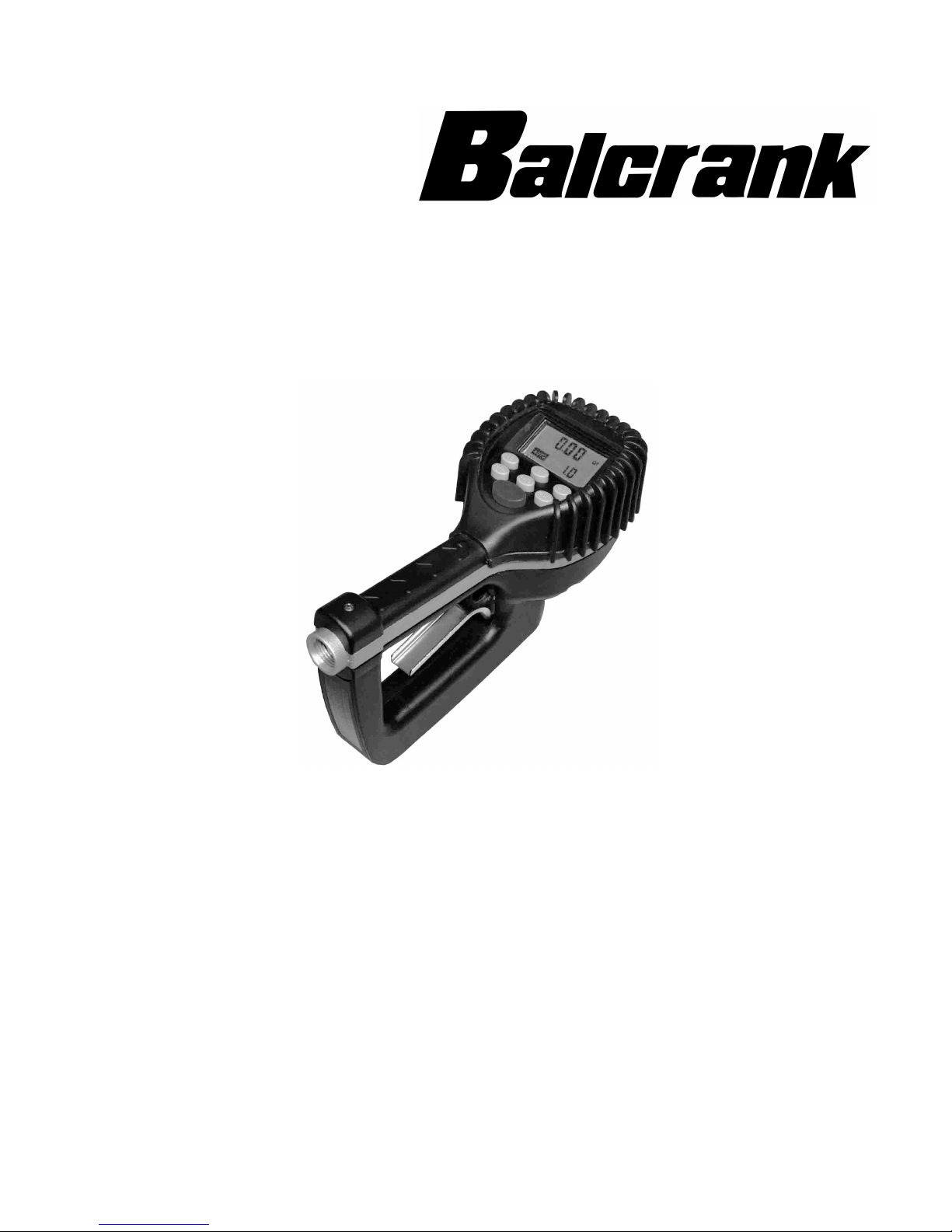
Electronic Preset Meter
Model:3331-028
Thoroughly read and understand this manual before
installing, operating or servicing this equipment.
_____________________________________________________________________________________________
OPERATION, INSTALLATION,
MAINTENANCE AND REPAIR GUIDE
Page 2

User Manual
CONTENTS
Safety . . . . . . . . . . . . . . . . . . . . . . . . . . . . . . . . . . . . . . . . . . . . . . . . . . . . . . . . . . . . . . . . . . . . . . . . . . . . . 4
Meter Buttons . . . . . . . . . . . . . . . . . . . . . . . . . . . . . . . . . . . . . . . . . . . . . . . . . . . . . . . . . . . . . . . . . . . . . . . 5
LCD Display . . . . . . . . . . . . . . . . . . . . . . . . . . . . . . . . . . . . . . . . . . . . . . . . . . . . . . . . . . . . . . . . . . . . . . . . . 5
Meter Installation . . . . . . . . . . . . . . . . . . . . . . . . . . . . . . . . . . . . . . . . . . . . . . . . . . . . . . . . . . . . . . . . . . . . . 6
Relieve System Pressure . . . . . . . . . . . . . . . . . . . . . . . . . . . . . . . . . . . . . . . . . . . . . . . . . . . . . . . . . . . . . . 6
Grounding . . . . . . . . . . . . . . . . . . . . . . . . . . . . . . . . . . . . . . . . . . . . . . . . . . . . . . . . . . . . . . . . . . . . . . . 6
Flushing Procedure . . . . . . . . . . . . . . . . . . . . . . . . . . . . . . . . . . . . . . . . . . . . . . . . . . . . . . . . . . . . . . . . . 6
Attach Meter to Hose . . . . . . . . . . . . . . . . . . . . . . . . . . . . . . . . . . . . . . . . . . . . . . . . . . . . . . . . . . . . . . . . 7
Attach Nozzle to Meter . . . . . . . . . . . . . . . . . . . . . . . . . . . . . . . . . . . . . . . . . . . . . . . . . . . . . . . . . . . . . . . 7
Meter Operation . . . . . . . . . . . . . . . . . . . . . . . . . . . . . . . . . . . . . . . . . . . . . . . . . . . . . . . . . . . . . . . . . . . . . . 8
Manual Mode . . . . . . . . . . . . . . . . . . . . . . . . . . . . . . . . . . . . . . . . . . . . . . . . . . . . . . . . . . . . . . . . . . . . . 8
Auto Batch Mode. . . . . . . . . . . . . . . . . . . . . . . . . . . . . . . . . . . . . . . . . . . . . . . . . . . . . . . . . . . . . . . . . . . 8
Operating Mode Functions . . . . . . . . . . . . . . . . . . . . . . . . . . . . . . . . . . . . . . . . . . . . . . . . . . . . . . . . . . . . . . . 9
Re-settable and Accumulated Totals . . . . . . . . . . . . . . . . . . . . . . . . . . . . . . . . . . . . . . . . . . . . . . . . . . . . . . 9
Emergency Override . . . . . . . . . . . . . . . . . . . . . . . . . . . . . . . . . . . . . . . . . . . . . . . . . . . . . . . . . . . . . . . . 9
Error Codes . . . . . . . . . . . . . . . . . . . . . . . . . . . . . . . . . . . . . . . . . . . . . . . . . . . . . . . . . . . . . . . . . . . . . . 9
Service . . . . . . . . . . . . . . . . . . . . . . . . . . . . . . . . . . . . . . . . . . . . . . . . . . . . . . . . . . . . . . . . . . . . . . . . . . . . 9
Low Battery . . . . . . . . . . . . . . . . . . . . . . . . . . . . . . . . . . . . . . . . . . . . . . . . . . . . . . . . . . . . . . . . . . . . . . 9
Changing the Batteries . . . . . . . . . . . . . . . . . . . . . . . . . . . . . . . . . . . . . . . . . . . . . . . . . . . . . . . . . . . . . . 10
Change Factory Settings . . . . . . . . . . . . . . . . . . . . . . . . . . . . . . . . . . . . . . . . . . . . . . . . . . . . . . . . . . . . . . . . 10
Verify Firmware Version. . . . . . . . . . . . . . . . . . . . . . . . . . . . . . . . . . . . . . . . . . . . . . . . . . . . . . . . . . . . . . 10
Programming . . . . . . . . . . . . . . . . . . . . . . . . . . . . . . . . . . . . . . . . . . . . . . . . . . . . . . . . . . . . . . . . . . . . 10
Change Unit of Measure . . . . . . . . . . . . . . . . . . . . . . . . . . . . . . . . . . . . . . . . . . . . . . . . . . . . . . . . . . . . . 11
Change Scale Factor. . . . . . . . . . . . . . . . . . . . . . . . . . . . . . . . . . . . . . . . . . . . . . . . . . . . . . . . . . . . . . . . 11
Save Changes . . . . . . . . . . . . . . . . . . . . . . . . . . . . . . . . . . . . . . . . . . . . . . . . . . . . . . . . . . . . . . . . . . . . 11
Verify Changes . . . . . . . . . . . . . . . . . . . . . . . . . . . . . . . . . . . . . . . . . . . . . . . . . . . . . . . . . . . . . . . . . . . 11
Calculate Scale Factor. . . . . . . . . . . . . . . . . . . . . . . . . . . . . . . . . . . . . . . . . . . . . . . . . . . . . . . . . . . . . . . . . . 12
Absolute Scale Factor . . . . . . . . . . . . . . . . . . . . . . . . . . . . . . . . . . . . . . . . . . . . . . . . . . . . . . . . . . . . . . . 12
Chart of Approximate Scale Factors . . . . . . . . . . . . . . . . . . . . . . . . . . . . . . . . . . . . . . . . . . . . . . . . . . . . . . 13
Dimensions . . . . . . . . . . . . . . . . . . . . . . . . . . . . . . . . . . . . . . . . . . . . . . . . . . . . . . . . . . . . . . . . . . . . . . . . 13
Specications . . . . . . . . . . . . . . . . . . . . . . . . . . . . . . . . . . . . . . . . . . . . . . . . . . . . . . . . . . . . . . . . . . . . . . . 14
Parts. . . . . . . . . . . . . . . . . . . . . . . . . . . . . . . . . . . . . . . . . . . . . . . . . . . . . . . . . . . . . . . . . . . . . . . . . . . . . 14
Troubleshooting . . . . . . . . . . . . . . . . . . . . . . . . . . . . . . . . . . . . . . . . . . . . . . . . . . . . . . . . . . . . . . . . . . . . . 16
August 2015
Page 3

Safety
SAFETY
IMPROPER GROUNDING, POOR VENTILATION, OPEN FLAMES OR SPARKS CAN CAUSE A HAZARDOUS CONDITION AND
RESULT IN AN EXPLOSION OR FIRE AND CAUSE SERIOUS INJURY.
• Be sure the fluid system is properly grounded. See your pump instruction manual for details.
• If there is static sparking or if you feel an electric shock while using the meter, stop dispensing immediately. Identify and
correct the problem before continuing.
• Provide fresh air ventilation. This will avoid the buildup of fumes from the fluid being dispensed.
• Do not smoke while dispensing flammable fluids.
• Keep the dispensing area free of debris including solvents, rags and spilled gasoline.
EQUIPMENT MISUSE CAN CAUSE THE METER TO RUPTURE OR MALFUNCTION AND CAUSE SERIOUS INJURY.
• This equipment is for professional use only.
• Read all instructions, tags and labels before operating the equipment.
• Use the equipment only for its intended purpose.
• Do not modify or alter the equipment.
• Do not leave equipment unattended while dispensing.
• Check equipment daily. Repair or replace worn or damaged parts immediately.
• Do not exceed the maximum working pressure level of the lowest rated system component.
• Use only extensions and nozzles that are designed for use with this equipment.
• Use only fluids and solvents that are compatible with the equipment. Read all fluid and solvent manufacturer’s warnings.
• Tighten all fluid connections before operating this equipment.
• Do not stop or deflect leaks with hands, body, gloves or rags.
• Do not dispense towards any person or any part of the body.
• Do not place hands or fingers over the end of or into the dispense valve.
• Comply with all local, state, and federal fire, electrical and safety regulations
• Use of this product in a manner other than specified in this manual may result in impaired operation or
damage to equipment.
THIS METER IS DESIGNED SPECIFICALLY TO DISPENSE PETROLEUM PRODUCTS. DO NOT USE FOR ANTIFREEZE
(ETHYLENE GLYCOL) SOLUTION, WINDSHIELD WIPER FLUID, BRAKE FLUID AND WATER BASED SOLUTIONS
Page 4 August 2015
Page 4
METER BUTTONS
Meter Buttons
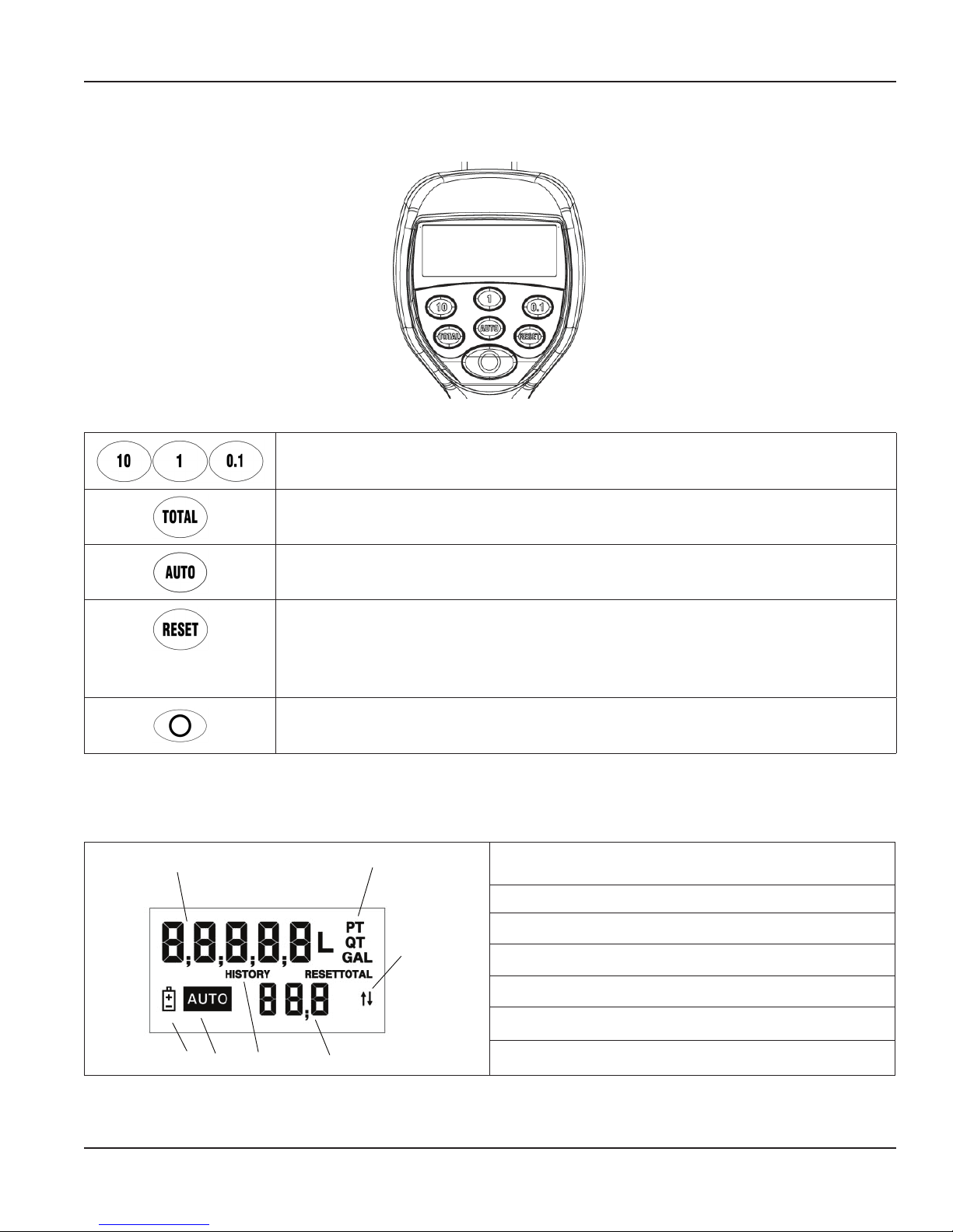
Figure 1: Meter button location
Used to enter the batch quantity to be dispensed.
Used to display the accumulated total of fluid dispensed as well as the re-settable total during
Auto Batch and Manual Mode.
LCD DISPLAY
1
Used to enter and exit the Manual or Auto Batch mode.
• Used in the Manual mode to clear the dispensed quantity.
• Used in the Auto Batch mode to clear the dispensed quantity and reset the meter for the
next batch.
• Used to reset the re-settable total dispensed while pressing the TOTAL button.
Used to stop the flow through an Emergency Override.
Table 1: Button descriptions
2
1. Displays Re-settable Total, Accumulated Total and Scale
Factor.
2. Displays Unit of Measure.
3. Arrow- not used.
3
4. Preset batch quantity.
5. History icon- not used.
7
5
6
6. Auto is an indicator of unit being in Auto Batch Mode.
4
Table 2: LCD display description
7. Low battery icon.
Page 5 August 2015
Page 5

Meter Installation
METER INSTALLATION
Relieve System Pressure
THIS EQUIPMENT STAYS PRESSURIZED UNTIL THE PRESSURE IS MANUALLY RELIEVED.
1. Turn o the power supply to the pump or close the shuto valve.
2. Dispense any uid in the system into a waste container by opening the meter.
3. Open all bleed-type master air valves and uid meter in the system.
4. Leave the meter open until ready to pressurize the system.
To reduce the risk of injury from fluid spray from the meter, follow this procedure when you:
• Are instructed to relieve pressure.
• Stop dispensing.
• Check, clean or service any system equipment.
• Clean or install nozzles.
Grounding
MOVEMENT OF FLUIDS THROUGH THE DISPENSING SYSTEM CREATES STATIC ELECTRICITY. STATIC ELECTRICITY CAN
CAUSE VOLATILE FUMES RESULTING IN AN EXPLOSION AND FIRE. THE DISPENSING SYSTEM MUST BE GROUNDED.
Grounding reduces the risk of static sparking. Ground all system components according to local, state and federal codes.
Consult the pump user manual and other system components to ground the following:
• Pump: follow manufacturer's recommendations
• Air and Fluid Hoses: use only grounded hoses
• Air Compressor: follow manufacturers recommendations
• Fluid Supply Container: follow the local code
Flushing Procedure
IF THIS INSTALLATION IS NEW OR IF THE FLUID IN THE LINES IS CONTAMINATED, FLUSH THE SYSTEM BEFORE
INSTALLING THE METER(S).
OTE:N If the system has multiple dispense positions, begin at the position farthest from the pump and move towards
the pump.
1. Close uid dispense valves at every position.
2. Once the main uid outlet valve at the pump is closed and the air pressure to the pump motor is properly adjusted, the air
valve is opened.
3. Slowly open the main uid valve.
4. Place the hose end in a waste container. Make sure the hose is secure so no uid leaks during ushing.
5. Slowly open the dispense valve and allow enough uid to pass through it to ensure that the system is clean.
6. Close the valve and repeat for all dispense positions.
Page 6 August 2015
Page 6
Attach Meter to Hose
Close the drain valve before starting this procedure.
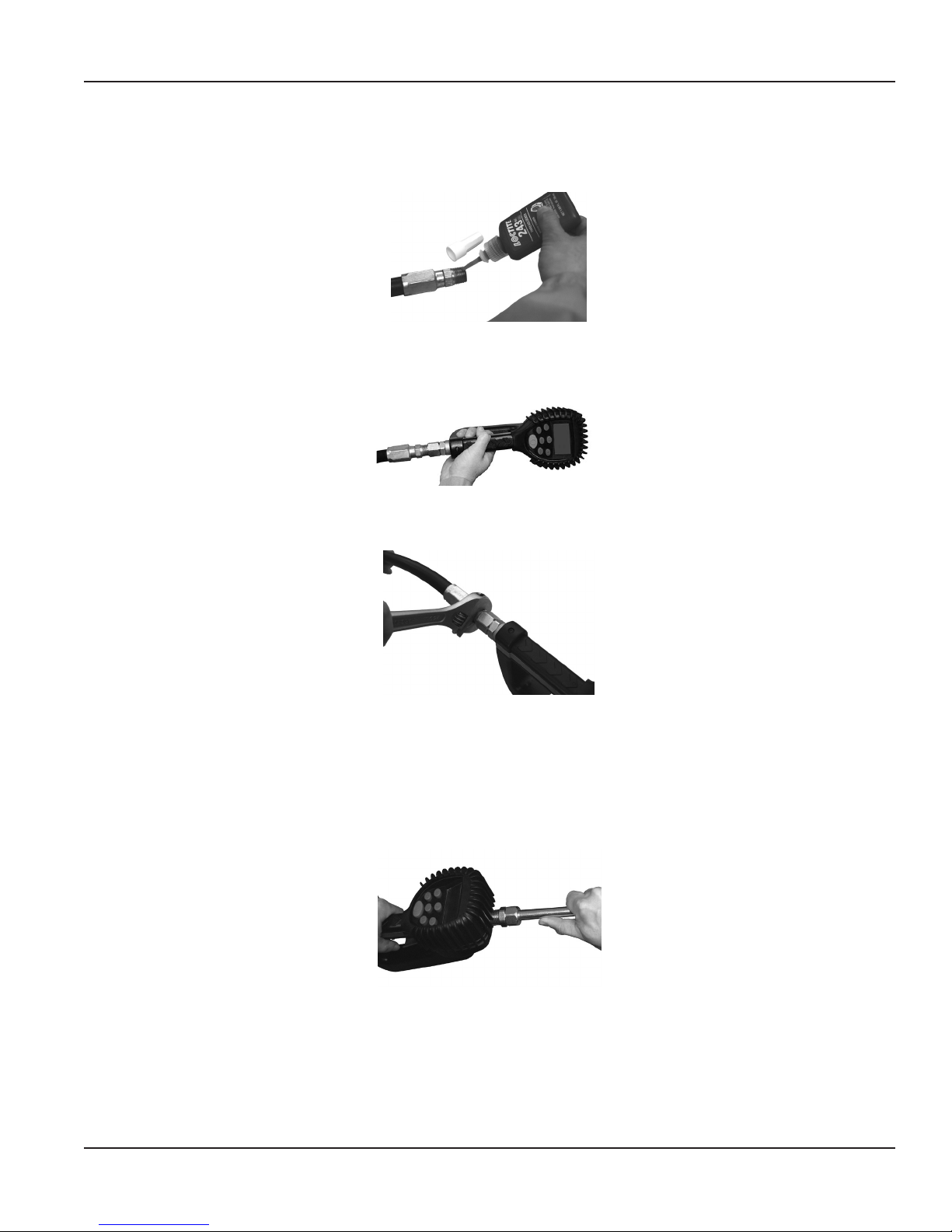
1. Attach swivel to meter. Apply Loctite® 243 sealant, or equivalent, to the male end of the hose. See Figure 2.
Figure 2: Apply thread sealant
2. Insert the metal end of the hose into the swivel. See Figure 3.
Figure 3: Insert hose into swivel
Meter Installation
3. Tighten completely with an open ended, adjustable, wrench. See Figure 4.
Figure 4: Use wrench to tighten
OTE:N The threaded end of the meter always has female threads. The metal end of the hose must have male threads. The
inlet and outlet swivel connections are either 1/2" NPT or 1/2" BSPP, depending on meter model.
Attach Nozzle to Meter
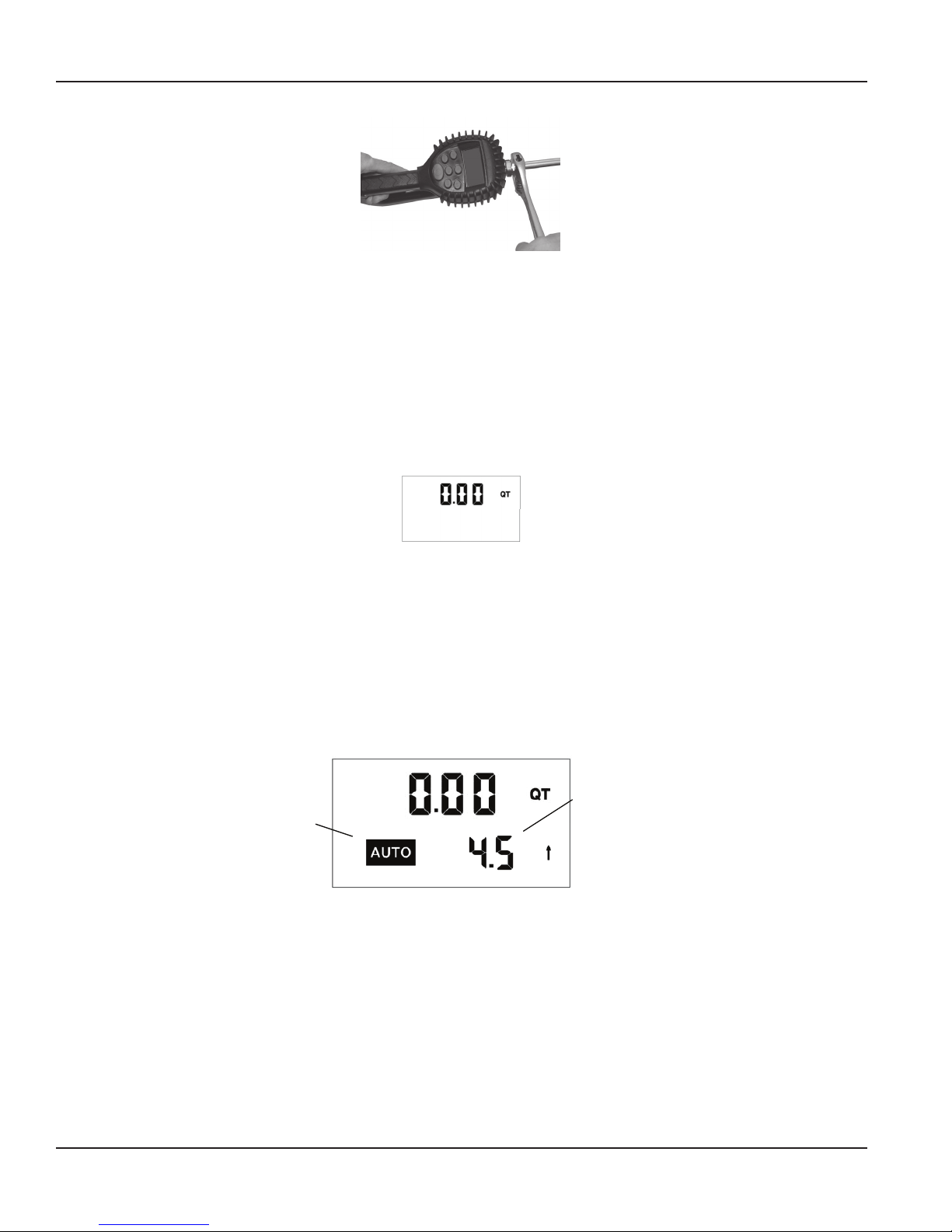
1. On the opposite end, apply Loctite® 243 sealant, or equivalent, to the end of the nozzle. Thread the nozzle onto the meter.
See Figure 5.
2. Screw it in tightly with an open-ended, adjustable, wrench. See Figure 6.
Figure 5: Thread nozzle onto meter
Page 7 August 2015
Page 7
Meter Operation
Figure 6: Tighten nozzle with wrench
3. Open all dispense position shuto valves. Start the pump to pressurize the system.
4. Before use, to ensure accuracy, purge all air from the uid lines and dispense valve(s).
METER OPERATION
OTE:N The keypad Auto button is used to toggle between Manual Mode and Auto Batch Mode.
Manual Mode
In Manual Mode the meter operates as a free flow-dispensing handle.
Figure 7: Manual mode screen
1. Pull the trigger to begin the ow.
2. The display shows the amount dispensed.
3. When the desired amount has been dispensed, release the trigger to stop the ow.
4. Press RESET once to reset the counter display to zero.
Auto Batch Mode
To enter Auto Batch Mode from Manual Mode press AUTO. When in Auto Batch Mode, the Auto icon displays and the batch
quantity shows in the lower right hand LCD display.
Auto Batch
Auto Icon
Figure 8: Auto batch mode display
1. Change the batch size by pressing 10, 1, and 0.1.
a. Press 10 to increase the batch amount in increments of 10 units.
b. Press 1 to increase the batch amount in increments of 1 unit.
c. Press 0.1 button to increase the batch amount in increments of 0.1 units.
2. Pull the trigger to begin the ow. The solenoid valve, in the meter, automatically locks the dispensing valve in the full
open position.
3. Release the trigger, allowing it to fall back.
4. The ow automatically shuts o after the batch quantity has dispensed.
Size
Page 8 August 2015
Page 8

Operating Mode Functions
5. After the batch quantity has been dispensed the meter is a free ow-dispensing handle until the reset button is depressed.
a. To top off the fluid, pull the trigger to being the flow and release it when the correct amount has been pumped.
OTE:N In case of an emergency or to interrupt a batch, the meter is equipped with an Emergency Override.
See "Emergency Override"
6. Press RESET when nished. The display resets and the meter is now ready for the next batch to be dispensed.
OPERATING MODE FUNCTIONS
These functions operate the same in Manual Mode and Auto Batch Mode.
Re-settable and Accumulated Totals
The meter has two flow totalizers, Re-settable Total and Accumulated Total.
1. Press and hold T
Resettable Total.
2. Resettotal displays the total fluid dispensed since the Re-settable Total was last set back to zero.
3. Press RESET while viewing Resettotal to set it back to zero.
4. Release TOTAL to return to the operating screen.
OTE:N The Accumulated Total cannot be reset unless the user changes from English units to metric units or from metric to
English units. See "Change Unit of Measure" on page 11.
OTAL to display Accumulated Total, after holding for three seconds the display changes to
Figure 9: Re-settable total display
Emergency Override
In case of an emergency or to interrupt a batch, the meter is equipped with an Emergency Override which closes the valve,
immediately stopping fluid flow.
1. Press O to activate the Emergency Override.
2. After an Emergency Override, batching can continue by pulling up on the trigger.
Error Codes
The meter has one error code that may display:
SF0 (Scale Factor 0) The Scale Factor setting for the meter is set to 0.000.
The code provides an indication, at the meter, that there is an error in communication between the meter and keypad. To
correct the error, input a valid Scale Factor for the meter follow the instructions in "Change Scale Factor" on page 11. All other
error codes are for factory purposes only. To clear the meter, press RESET.
SERVICE
Low Battery
When the batteries need to be changed a progression of warnings appears on the meter screen. First, the Low Battery icon will
appear on the display, this means that the batteries are getting low, and should be changed. When the icon begins to flash,
the battery power is too low, and meter functions are disabled.
Low Battery
Icon
Figure 10: Low battery icon
AUT-UM-00933-EN-05
Page 9 August 2015
Page 9
Change Factory Settings
Changing the Batteries
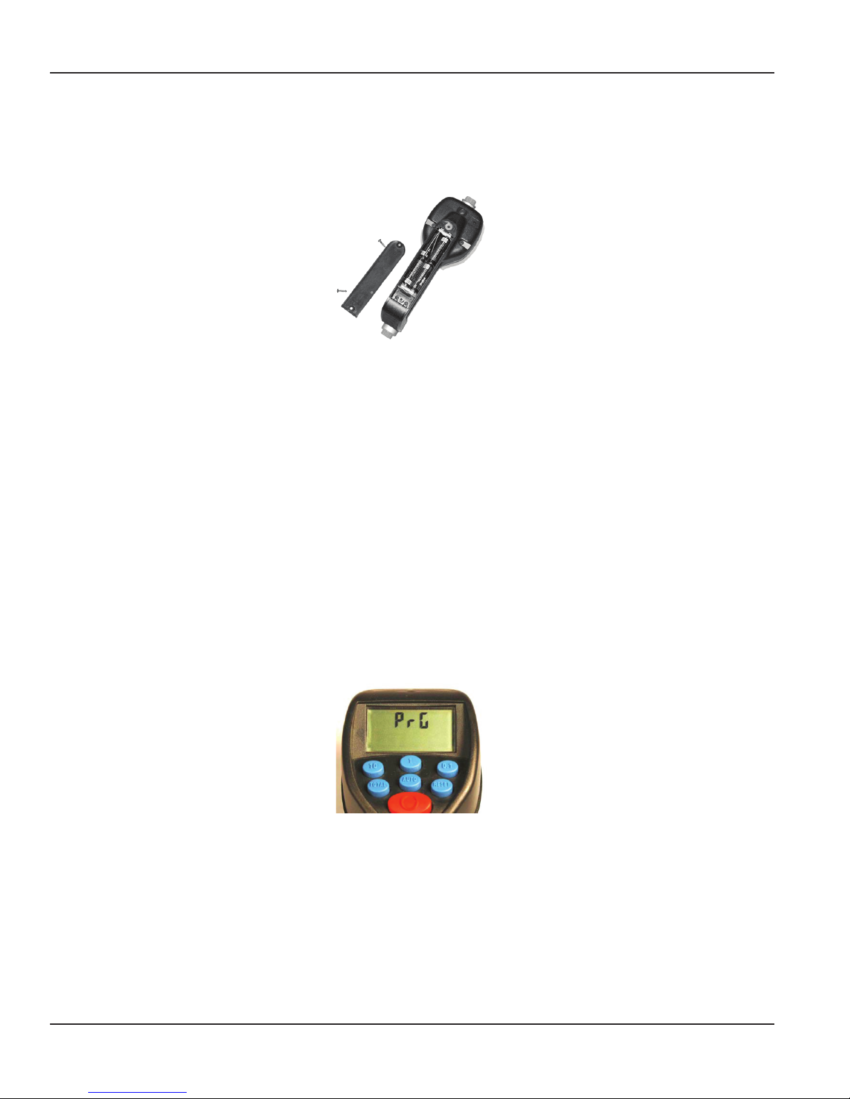
The battery compartment is located in the lower case on the underside of the trigger guard.
1. Turn the unit face down.
2. Unscrew the two screws. Remove the battery door to expose the batteries.
Figure 11: Replacing the batteries
3. Replace the old batteries. The meter takes four AA, alkaline, batteries. Battery polarity markings are inside the
battery compartment.
4. Dispose of used batteries properly, according to local regulations.
OTE:N Changing the batteries does not affect any of the programmed values or totals.
CHANGE FACTORY SETTINGS
Each meter is calibrated at the factory for use with motor oil. See "Change Scale Factor" on page 11 The Unit of Measure is also
selected prior to shipment.
Verify Firmware Version
The firmware version and code checksum are displayed by pressing and holding TOTAL and 1 simultaneously. The last two
digits on the lower right are the firmware version. Meters with version 16 or higher use the procedure outlined in this manual
for changing the unit of measure, scale factor and enabling or disabling the EPM functionality.
Programming
1. Press and hold TOTA L and AUTO simultaneously. PrG will appear on the display.
Figure 12: Entering programming mode
2. Release the buttons.
3. Press and release these buttons in order: 1, AUTO, 10, 0.1, and TOTAL.
4. The current unit of measure will now be ashing indicating that you have entered the programming mode.
Page 10 August 2015
Page 10

Change Factory Settings
Change Unit of Measure
The meter comes with an option to choose four different units of measure.
Scale Factor
Digits
Unit of Measure
Figure 13: Unit of measure display
1. The current unit of measure will ash when Programming Mode is entered.
2. Press TOTA L to toggle amongst the four options; PT, QT, GAL, L.
3. When the correct unit of measure is displayed, press RESET to select it. The unit of measure will stop ashing.
4. If L (liters) is selected, the decimal point will being to ash. The decimal point can either be changed to a comma or a
period. To do this press TOTAL .
5. If no scale factor changes are necessary, see "Save Changes" on page 11.
CHANGING THE UNIT OF MEASUREMENT FROM METRIC TO ENGLISH OR FROM ENGLISH TO METRIC CLEARS THE
RE-SETTABLE TOTAL AND ACCUMULATED TOTAL.
Change Scale Factor
CHANGING THE SCALE FACTOR CHANGES THE ACCURACY OF THE METER, POTENTIALLY CAUSING IT TO OVERFILL OR
UNDER FILL. THIS HAS THE POTENTIAL TO CAUSE A MECHANICAL BREAKDOWN.
Scale factor digits
Figure 14: Scale factor display
1. Press RESET to advance through the scale factor digits.
2. To change the selected number, press TOTAL.
OTE:N All digits can be scrolled between 0 and 9 except the first. It can only be toggled from 0 to 1 or from 1 to 0.
3. Press RESET to advance to the next digit in the scale factor.
4. Repeat steps 2 and 3 for all ve digits.
Save Changes
To save changes and exit programming mode:
1. Press and hold TOTA L and AUTO simultaneously.
2. The display will ash three times and go blank.
3. Press RESET and the display will turn back on.
Verify Changes
1. Verify unit of measure is correct.
2. Press and hold TOTA L and AUTO simultaneously to verify the scale factor is correct.
Page 11 August 2015
Page 11

Calculate Scale Factor
CALCULATE SCALE FACTOR
A Scale Factor is a number used to adjust meter accuracy. The Scale Factor is set at the factory using motor oil with a viscosity
of 10W. The primary use for Scale Factor recalibration is to batch fluids with different viscosities. If the fluid has a lower
viscosity, more fluid can slip past the meter gears without being detected. Changing the Scale Factor adjusts the meter to
compensate for the loss. The meter multiplies each pulse by the Scale Factor number to correct the accuracy when it converts
to the specified units. For an approximate Scale Factor for fluids of different viscosities, see "Chart of Approximate Scale Factors"
on page 13.
OTE:N The meter’s original Scale Factor was written on the trigger when it was calibrated at the factory. It may have been
revised after field installation. Use the Scale Factor showing on the display, not on the trigger.
CHANGING THE SCALE FACTOR WILL CHANGE THE ACCURACY OF THE METER, POTENTIALLY CAUSING IT TO OVERFILL
OR UNDER FILL. THIS HAS THE POTENTIAL TO CAUSE A MECHANICAL BREAKDOWN.
To view the current scale factor, press and hold TOTAL and AUTO simultaneously.
Absolute Scale Factor
For absolute scale factor, preform this test:
1. Run a measured amount of uid through the meter.
2. If the meter delivers 4.20 quarts and the display shows only 4.00 quarts, then the Scale Factor needs to be adjusted.
3. Divide what the meter delivered (4.20) by what the display shows (4.00). You get an error factor of (1.05).
4. The existing Scale Factor is 1.0123, as shown in steps 1 and 2 in "Verify Changes".
5. To calculate a new factor: 1.0123 (existing Scale Factor) x 1.05 (error factor) = 1.0629 (new Scale Factor).
6. Enter that number as described in the "Change Scale Factor" on page 11.
OTE:N Use the Scale Factor shown on the display, not on the trigger.
Page 12 August 2015
Page 12
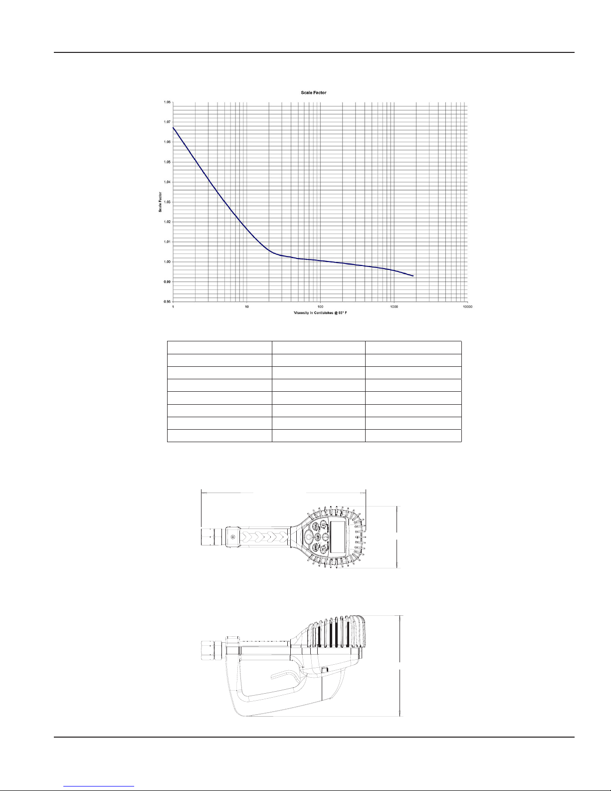
Chart of Approximate Scale Factors
Figure 15: Scale factors for fluids with different viscosities
Dimensions
DIMENSIONS
Fluid Viscosity Scale Factor
Water/anti-freeze 5
Anti-freeze 18 1.007
Brake Fluid 42 1.004
ATF 80 1.002
10W 140 1.000
80W-90 450 0.999
140W 1800 0.993
Table 3: Fluid viscosity and scale factor
11.3 in. (287.02 mm)
4.3 in. (109.22 mm)
1.044
7.0 in. (177.8 mm)
Figure 16: Meter dimensions
Page 13 August 2015
Page 13
Specications
SPECIFICATIONS
Maximum flow * 10 gpm (38 lpm)
Minimum flow * 0.25 gpm (1 lpm)
Operating pressure (maximum) 1000 psi (67 bar)
Operating pressure (minimum) 5 psi (0.35 bar)
Operating temperature (maximum) 120° F (50° C)
Operating temperature (minimum) 20° F (-5° C)
Accuracy (general) +/- 0.5%
Accuracy (anti-freeze) +/- 1.5%
5-digit LCD display Quarts, Pints, Gallons, Liters
Inlet and outlet connections 1/2" NPT (1/2" BSPP)
* Minimum and maximum flow range will vary with fluid viscosity
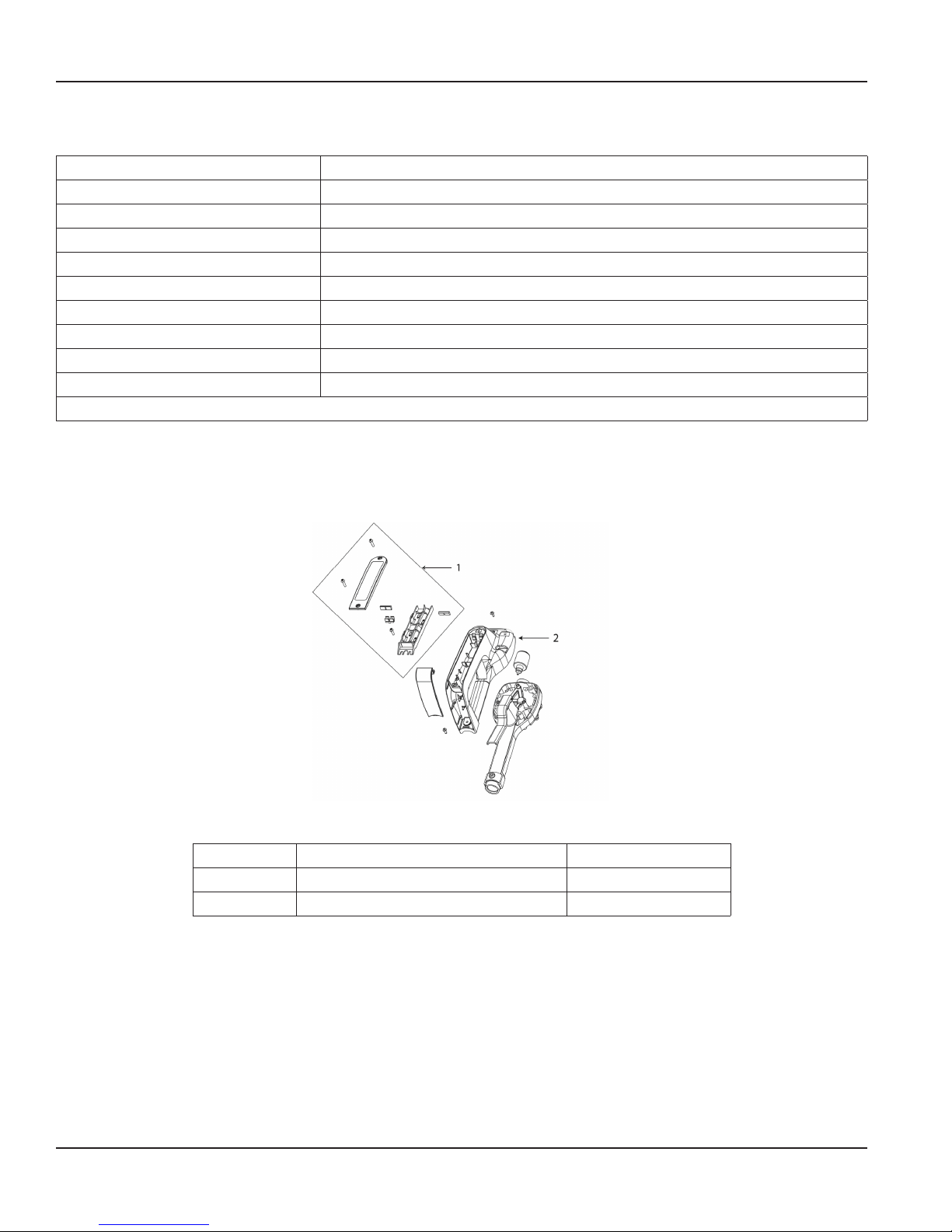
Table 4: Part numbers: inside meter
PARTS
Item Description Part Number
1 Battery holder assembly 64103-026
2 Bottom case with screws 64103-003
Page 14 August 2015
Figure 17: Parts: back of meter
Table 5: Part numbers: back of meter
Page 14
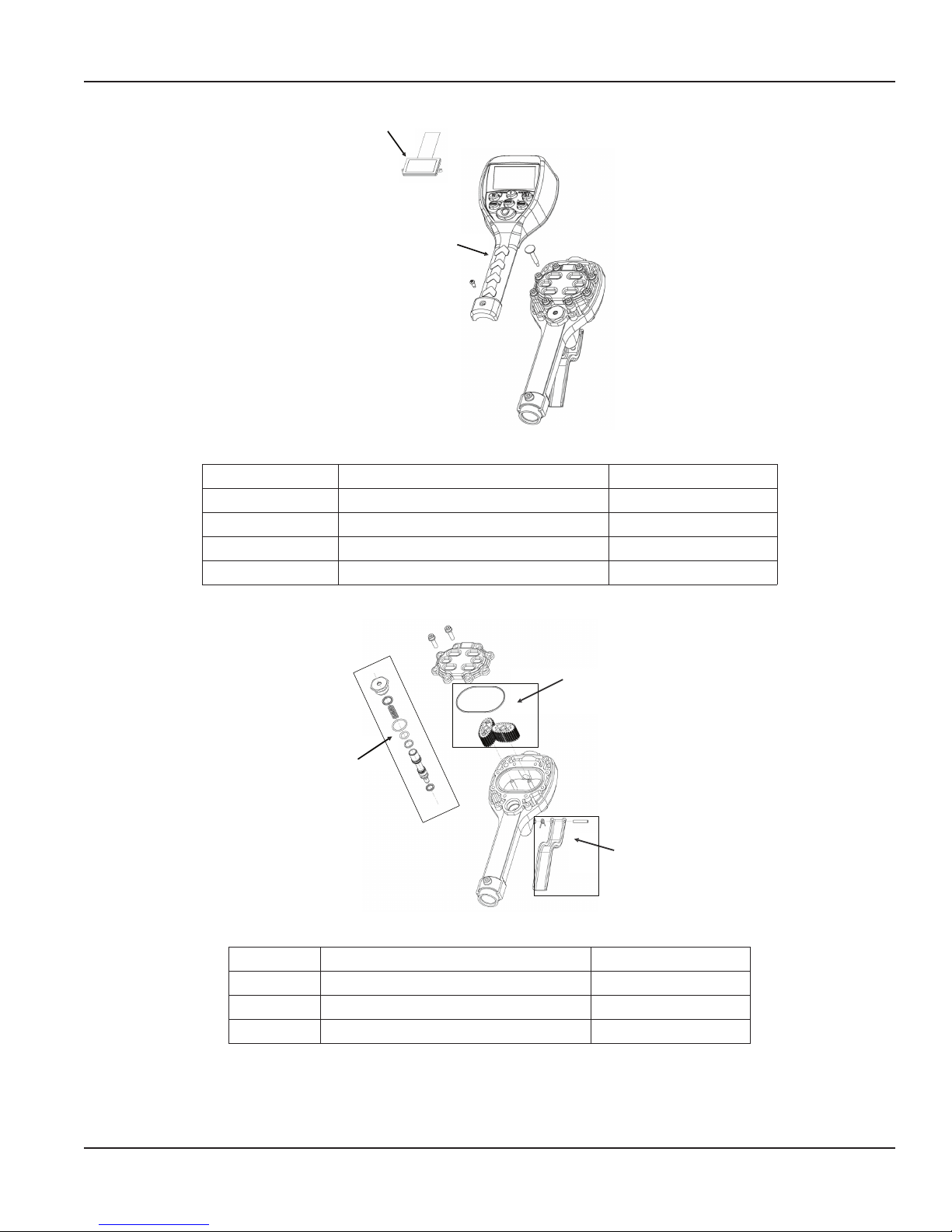
1
2
Figure 18: Parts: front of meter
Item Description Part Number
1 Display assembly 64103-023
2 EPM2 std. register assembly 64103-024
Not shown Swivel, NPT, special fluids 64082-001
Not shown Rubber boot 65546-001
Table 6: Part numbers: front of meter
Parts
2
1
3
Figure 19: Parts: inside meter
Item Description Part Number
1 Valve assembly 64103-010
2 Gear service kit with O-ring 62896-001
3 Trigger Assembly 64103-005
Table 7: Part numbers: inside meter
Page 15 August 2015
Page 15
Electronic Preset Meter, Model EPM2-STD, Standard Series
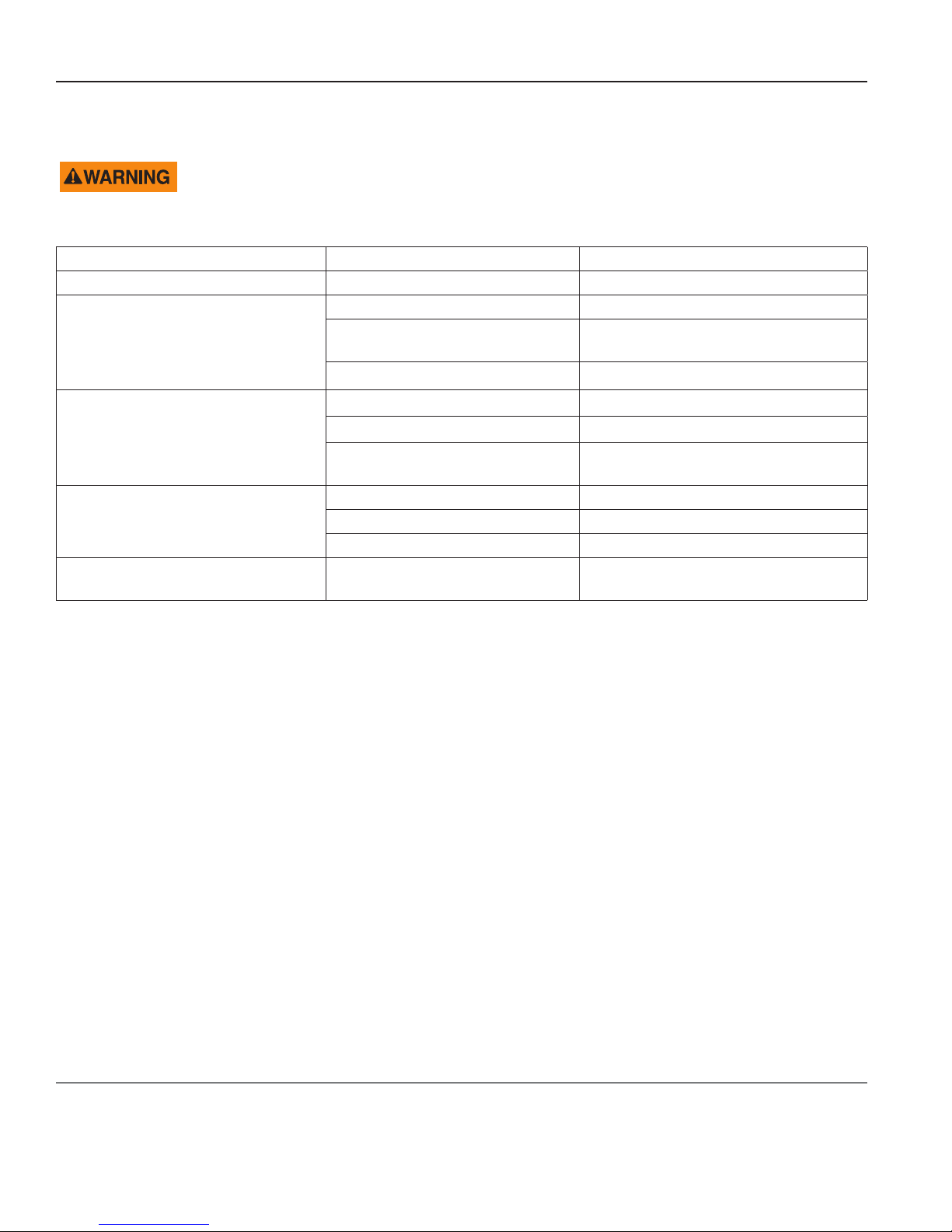
TROUBLESHOOTING
RELIEVE THE PRESSURE PRIOR TO CHECKING OR REPAIRING THE METER. MAKE SURE ALL VALVES, CONTROLS AND
PUMPS ARE OPERATING CORRECTLY.
Symptom Possible Cause Remedy
Battery icon is displayed Batteries are low Replace batteries
Meter asleep Press RESET
Display blank
Meter does not latch for batching
Slow or no fluid flow
Meter inaccurate Scale Factor not correct for fluid
Loose battery connection
Batteries dead Replace batteries / press RESET
Meter not in Auto Mode Press AUTO and program the batch size
Meter not reset after prior batch Press RESET
Low batteries
Filter is clogged Clean or replace the filter in the swivel nut
Pump pressure is low Turn up the pump pressure
Foreign material is jamming meter Contact your local distributor for repair
Remove battery pack and check battery
connection / press RESET
Check for battery icon / replace batteries /
press RESET
Enter Program Mode, check and reset
the Scale Factor
Page 16

For Warranty Information Visit:
www.balcrank.com
Balcrank™ Corporation
Weaverville, NC 28787
800-747-5300
800-763-0840 Fax
www.balcrank.com
SERVICE BULLETIN SB3109
Revision A - 10/2016
Revision Log:
Rev. A - Release
 Loading...