

Balcar R410A User Manual
FILE NO. A03-002F
SERVICE MANUAL/INTEGRATION
<OWNERS MANUAL/INSTALLATION MANUAL>
SPLIT TYPE
OUTDOOR UNIT
<SUPER DIGITAL INVERTER>
RAV-SP560AT-E, RAV-SP800A T-E, RAV -SP1100AT-E, RAV -SP1400AT-E
<DIGITAL INVERTER>
RAV-SM560AT-E, RAV-SM800AT-E, RAV -SM1100AT-E, RAV-SM1400AT-E
INDOOR UNIT
<SUPER DIGITAL INVERTER>
RAV-SP1100UT-E
<DIGITAL INVERTER>
RAV-SM560UT-E, RAV -SM560BT-E, RAV -SM561BT-E, RAV-SM561CT-E,
RAV-SM800UT-E, RAV -SM800BT-E, RAV -SM801BT-E, RAV-SM801CT-E,
RAV-SM1100UT-E, RAV-SM1101CT-E, RAV -SM1101BT-E,
RAV-SM1400UT-E, RAV -SM1401CT-E, RAV-SM1401BT-E
R410A
PRINTED IN JAPAN, Jun.,2004 ToMo
ADOPTION OF NEW REFRIGERANT
This Air Conditioner is a new type which adopts a new refrigerant HFC (R410A) instead of the con ventional
refrigerant R22 in order to prevent destruction of the oz one layer.
WARNING
Cleaning of the air filter and other parts of the air filter involves dangerous work in high places, so be sure to ha ve
a service person do it. Do not attempt it yourself. The cleaning diagram for the air filter is there f or the service
person, and not for the customer.
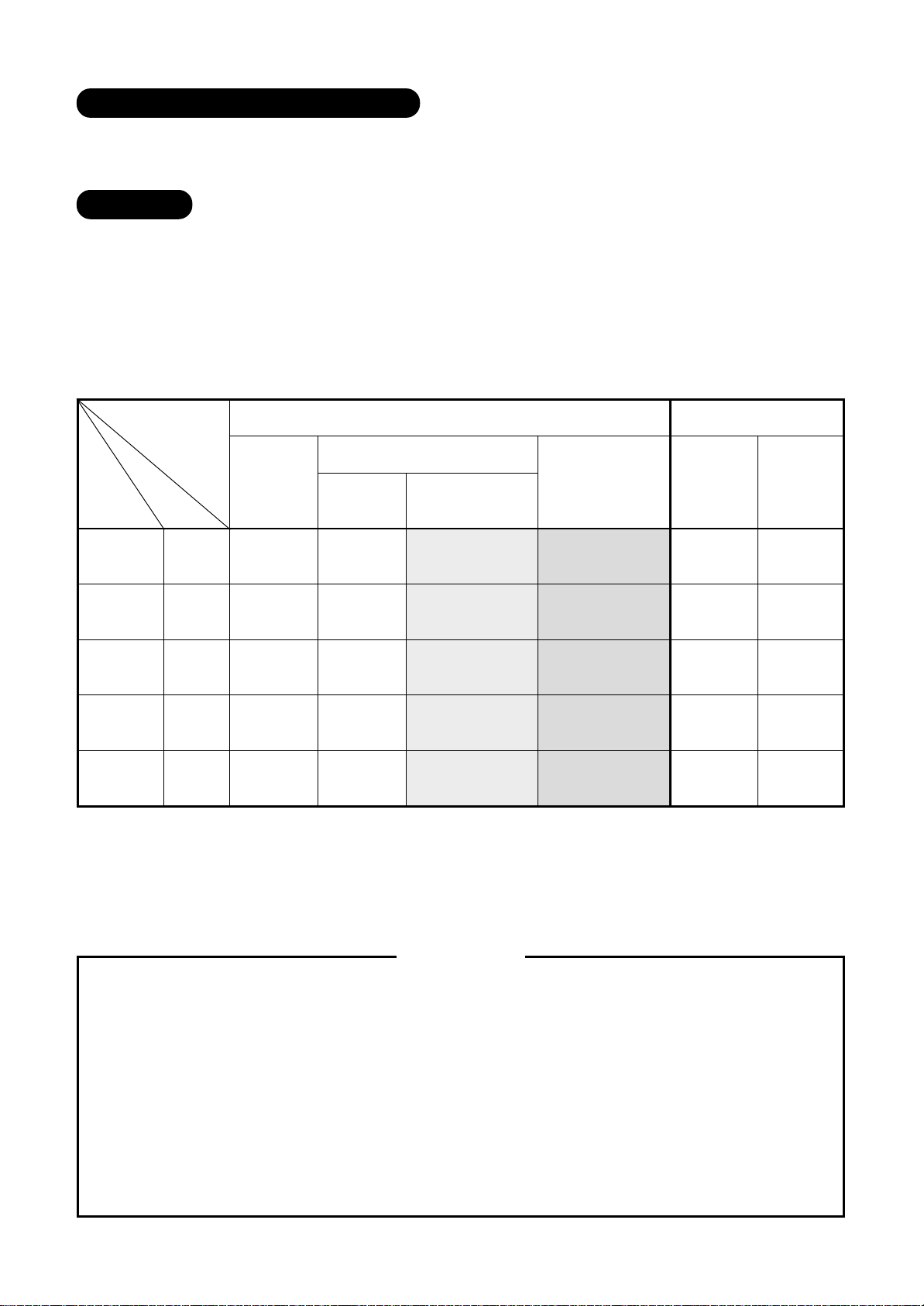
Service Manual Table
FILE NO. for Owner’s Manual / Service Manual
Type
RAV- name
SM560 O/M
S/M
SM800 O/M
S/M
SM1100 O/M
S/M
SM1400 O/M
S/M
SP1100 O/M
S/M
Indoor unit
BT-E
∗∗∗∗
∗∗
∗∗∗∗
CT-E
1CT-E
UT-E
A02-013 A02-013 A03-006 A03-015
A02-014 A02-014 A03-007 A03-016
A02-013 A02-013 A03-006 A03-015
A02-014 A02-014 A03-007 A03-016
A03-002 — A03-006 A03-015
A03-003 A03-007 A03-016
A03-002 — A03-006 A03-015
A03-003 A03-007 A03-016
A03-013 — — —
A03-014
AC motor DC motor
∗∗∗∗
∗∗
∗∗∗∗
0BT-E
1BT-E
∗∗∗∗
∗∗
∗∗∗∗
O/M : OWNER’S MANUAL, INSTALLATION MANUAL
∗
S/M : SERVICE MANUAL
∗
Outdoor unit
AT-E SP
AT-E
∗∗∗∗∗∗
∗∗∗
∗∗∗∗∗∗
A02-013 A03-013
A02-014 A03-014
A02-013 A03-013
A02-014 A03-014
A03-002 A03-013
A03-003 A03-014
A03-002 A03-013
A03-003 A03-014
— A03-013
A03-014
Concerning models for RAV -SM
NO TICE
KRT-E, and RAV-SM
∗∗∗∗∗∗∗∗
∗∗∗∗
∗∗∗∗∗∗∗∗
Toshiba Carrier (Thailand) Co., Ltd.
144/9 Moo 5, BangKadi Indastrial park,
Tivanon Road, Tambol BangKadi, Amphur Muang,
Pathumthani 12000, Thailand
Tel : +66-2-501-1390
Fax : +66-2-501-1130
XT-E, please contact the fo llowing address ;
∗∗∗∗∗∗∗∗
∗∗∗∗
∗∗∗∗∗∗∗∗

CONTENTS
OUTDOOR
INSTALLATION MANUAL
RAV-SM560AT-E, RAV-SM800AT-E....................................................................... 5
RAV-SM1100AT-E, RAV-SM1400AT-E................................................................. 19
INDOOR
OWNERS MANUAL
4-Way Air Discharge Cassette Type
RAV-SM560UT-E, RAV-SM800UT-E, RAV-SM1100UT-E, RAV-SM1400UT-E ...... 33
Concealed Duct Type
RAV-SM560BT-E, RAV-SM800BT-E,
RAV-SM561BT-E, RAV-SM801BT-E, RAV-SM1101BT-E, RAV-SM1401BT-E ...... 47
Under Ceiling Type
RAV-SM561CT-E, RAV-SM801CT-E, RAV-SM1101CT-E, RAV-SM1401CT-E ...... 61
INSTALLATION MANUAL
4-Way Air Discharge Cassette Type
RAV-SM560UT-E, RAV-SM800UT-E, RAV-SM1100UT-E, RAV-SM1400UT-E ...... 76
Concealed Duct Type
RAV-SM560BT-E, RAV-SM800BT-E,
RAV-SM561BT-E, RAV-SM801BT-E, RAV-SM1101BT-E, RAV-SM1401BT-E ...... 95
Under Ceiling Type
RAV-SM561CT-E, RAV-SM801CT-E, RAV-SM1101CT-E, RAV-SM1401CT-E .... 121
ACCESSORIES
OWNERS MANUAL ........................................................................ 144
INSTALLATION MANUAL ........................................................... 158
– 3 –

OUTDOOR
CONTENTS
INSTALLATION MANUAL
RAV-SP560AT-E, RAV-SP800AT-E
RAV-SM560AT-E, RAV-SM800AT-E
1
PRECAUTIONS FOR SAFETY .................................................................... 5
2
ACCESSORY AND REFRIGERANT............................................................ 6
3
SELECTION OF INSTALLATION .................................................................7
4
REFRIGERANT PIPING............................................................................. 12
5
EVACUATING ............................................................................................. 14
6
ELECTRICAL WORK ................................................................................. 16
7
FINAL INSTALLATION CHECKS............................................................... 17
RAV-SP1100AT-E, RAV-SP1400AT-E
RAV-SM1100AT-E, RAV-SM1400AT-E
1
PRECAUTIONS FOR SAFETY .................................................................. 19
2
ACCESSORY AND REFRIGERANT.......................................................... 20
3
SELECTION OF INSTALLATION ...............................................................21
4
REFRIGERANT PIPING............................................................................. 25
5
EVACUATING ............................................................................................. 27
6
ELECTRICAL WORK ................................................................................. 29
7
FINAL INSTALLATION CHECKS............................................................... 30
– 4 –
RAV -SP1100, 1400AT-E
RAV -SM1100, 1400AT-E
1
• Ensure that all Local, National and International regulations are satisfied.
• Read this “PRECAUTIONS FOR SAFETY” carefully before Installation.
• The precautions described below include the important items regarding safety. Observe them without fail.
• After the installation work, perform a trial operation to check for any problem.
Follow the Owner’s Manual to explain how to use and maintain the unit to the customer.
• Turn off the main power supply switch (or breaker) before the unit maintenance.
• Ask the customer to keep the Installation Manual together with the Owner’s Manual.
PRECAUTIONS FOR SAFETY
CAUTION New Refrigerant Air Conditioner Installation
• THIS AIR CONDITIONER ADOPTS THE NEW HFC REFRIGERANT (R410A) WHICH DOES NOT DE-
STROY OZONE LAYER.
The characteristics of R410A refrigerant are ; easy to absorb water, oxidizing membrane or oil, and its pressure
is approx. 1.6 times higher than that of refrigerant R22. Accompanied with the ne w refrigerant, refrigerating oil
has also been changed. Therefore , during installation work, be sure that water, dust, former refrigerant, or
refrigerating oil does not enter the refrigerating cycle.
To prevent charging an incorrect refrigerant and refrigerating oil, the sizes of connecting sections of charging
port of the main unit and installation tools are charged from those for the conventional refrigerant.
Accordingly the exclusive tools are required for the new refrigerant (R410A).
For connecting pipes, use new and clean piping designed for R410A, and please care so that water or dust
does not enter. Moreover, do not use the existing piping because there are problems with pressure-resistance
force and impurity in it.
CAUTION To Disconnect the Appliance from Main Power Supply.
This appliance must be connected to the main power supply by means of a switch with a contact separation of
at least 3 mm.
The installation fuse (25A D type ) must be used for the power supply line of this conditioner.
WARNING
• Ask an authorized dealer or qualified installation professional to install/maintain the air condi-
tioner.
Inappropriate installation may result in water leakage, electric shock or fire.
• Turn off the main power supply switch or breaker before attempting any electrical work.
Make sure all power switches are off. Failure to do so may cause electric shock.
• Connect the connecting cable correctly.
If the connecting cable is connected in a wrong way, electric parts may be damaged.
• When moving the air conditioner for the installation into another place, be very careful not to
enter any gaseous matter other than the specified refrigerant into the refrigeration cycle.
If air or any other gas is mixed in the refrigerant, the gas pressure in the refrigeration cycle becomes abnormally high and it may resultingly causes pipe burst and injuries on persons.
• Do not modify this unit by removing any of the safety guards or by by-passing any of the safety
interlock switches.
• Exposure of unit to water or other moisture before installation may cause a short-circuit of
electrical parts.
Do not store it in a wet basement or expose to rain or water.
• After unpacking the unit, examine it carefully if there are possible damage .
• Do not install in a place that might increase the vibration of the unit.
• To avoid personal injury (with sharp edges), be careful when handling parts.
• Perform installation work properly according to the Installation Manual.
Inappropriate installation may result in water leakage, electric shock or fire.
– 19 –

RAV -SP1100, 1400AT-E
RAV -SM1100, 1400AT-E
• When the air conditioner is installed in a small room, provide appropriate measures to ensure
that the concentration of refrigerant leakage occur in the room does not exceed the critical
level.
• Install the air conditioner securely in a location where the base can sustain the weight adequately .
• Perform the specified installation work to guard against an earthquake.
If the air conditioner is not installed appropriately, accidents may occur due to the falling unit.
• If refrigerant gas has leaked during the installation work, ventilate the room immediately.
If the leaked refrigerant gas comes in contact with fire, noxious gas may generate.
• After the installation work, confirm that refrigerant gas does not leak.
If refrigerant gas leaks into the room and flows near a fire source, such as a cooking range, noxious gas
might generate.
• Electrical work must be performed by a qualified electrician in accordance with the Installation
Manual. Make sure the air conditioner uses an exclusive power supply.
An insufficient power supply capacity or inappropriate installation may cause fire.
• Use the specified cables for wiring connect the terminals securely fix. To prevent external
forces applied to the terminals from affecting the terminals.
• Be sure to provide grounding.
Do not connect ground wires to gas pipes, water pipes, lightning rods or g round wires for telephone cables.
• Conform to the regulations of the local electric company when wiring the power supply.
Inappropriate grounding may cause electric shock.
• Do not install the air conditioner in a location subject to a risk of exposure to a combustible gas.
If a combustible gas leaks, and stays around the unit, a fire may occur.
Required tools for installation work
1) Philips screw driver
2) Hole core drill (65 mm)
3) Spanner
4) Pipe cutter
5) Knife
6) Reamer
7) Gas leak detector
8) Tape measure
9) Thermometer
2
ACCESSORY AND REFRIGERANT
10) Mega-tester
11) Electro circuit tester
12) Hexagonal wrench
13) Flare tool
14) Pipe bender
15) Level vial
16) Metal saw
R410A (Special requirement)
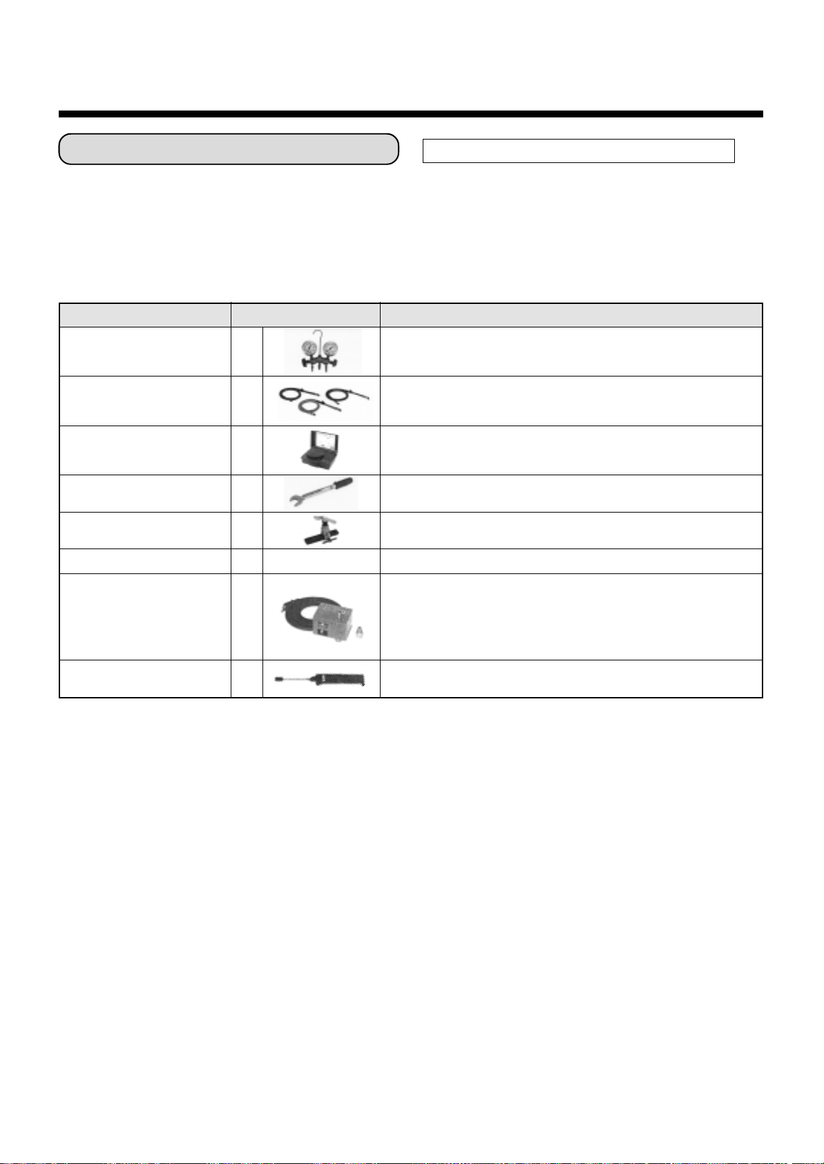
17) Gauge manifold
(Charge hose : R410A special requirement)
18) Vacuum pump
(Charge hose : R410A special requirement)
19) Torque wrench
1/4 (17 mm) 16 N•m (1.6 kgf•m)
3/8 (22 mm) 42 N•m (4.2 kgf•m)
1/2 (26 mm) 55 N•m (5.5 kgf•m)
5/8 (15.9 mm) 120 N•m (12.0 kgf•m)
20) Copper pipe gauge adjusting projection margin
21) Vacuum pump adapter
Accessory and Installation Parts Refrigerant Piping
• Piping kit used for the conventional refrigerant cannot be
used.
1
Outdoor unit
Installation manual x 1
Drain nipple
2
Waterproof rubber cap
3
Protective bush
4
Guard material for
passage part
• Use copper pipe with 0.8 mm or more thickness for Ø9.5.
Use copper pipe with 1.0 mm or more thickness for
Ø15.9.
• Flare nut and flare works are also different from those of
the conventional refrigerant. Take out the flare nut
attached to the main unit of the air conditioner, and use it.
– 20 –
RAV -SP1100, 1400AT-E
RAV -SM1100, 1400AT-E
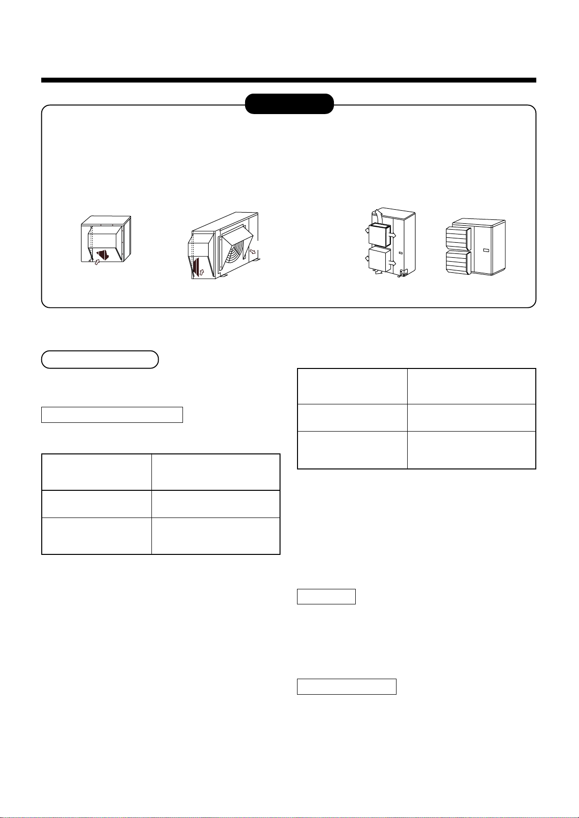
3
SELECTION OF INSTALLATION
CAUTION
<SP1100AT-E, SP1400AT-E only>
When using an air conditioner under low outside temperature condition (Outside temp .:–5°C or lo wer) with
COOL mode, prepare a duct or wind shield so that it is not affected b y the wind.
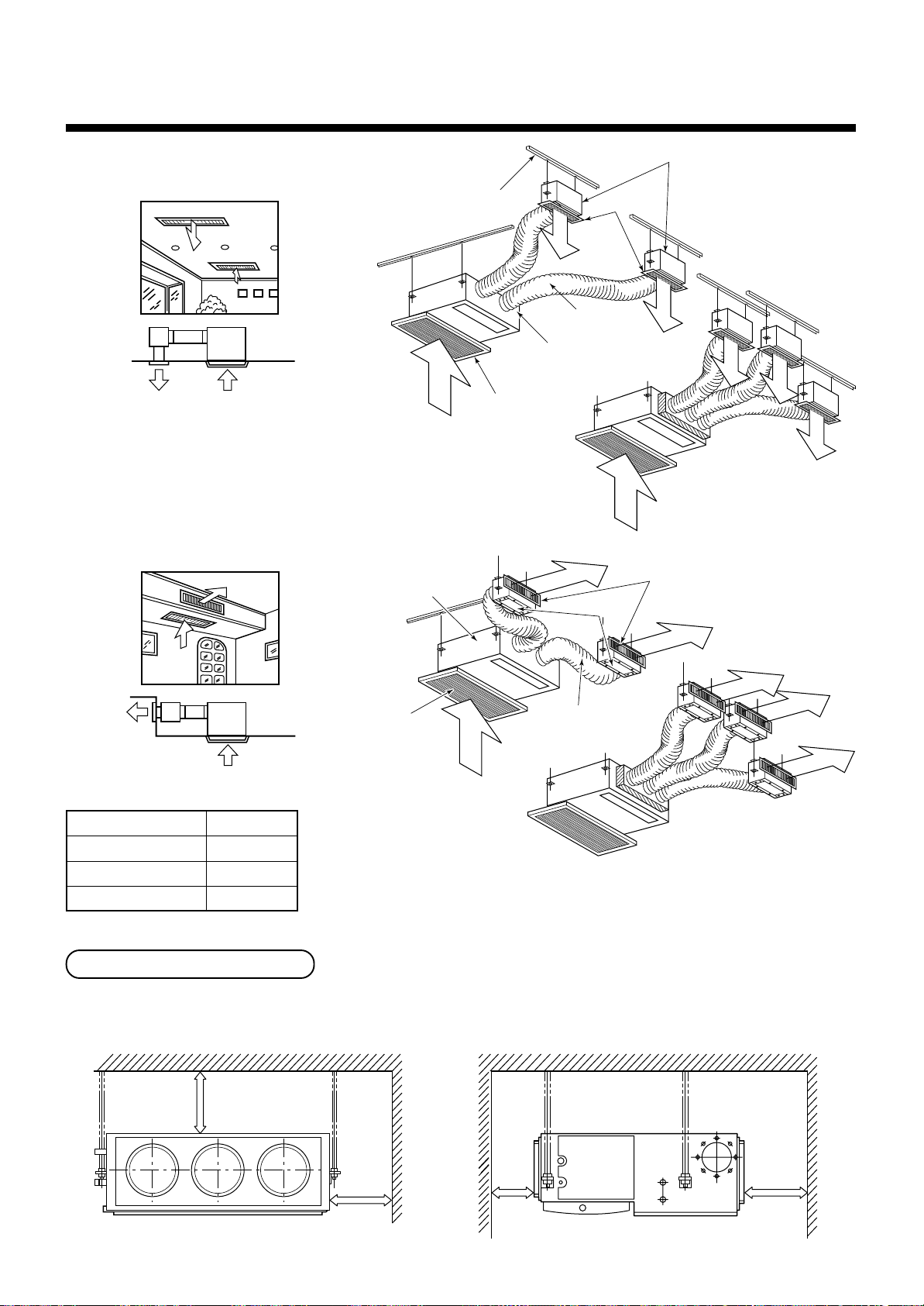
<Example>
Discharge upward/downward
Suction hood (Rear side)
Fin
Suction
Suction hood (Side)
Discharge hood
Fin
Suction
Discharge
( )
or leftward is also available.
Use it at location
where a side wind
drives thickly
Before installation
Be careful to the following items before installation.
Length of refrigerant pipe
<SM1100AT-E, SM1400AT-E>
Length of refrigerant pipe
connected to
indoor/outdoor unit
20m or shorter
21m to 50m
*
Addition of refrigerant is
unnecessary at the local site.
<Addition of refrigerant>
Add 40g of refrigerant for every
1m of pipe which exceeds 20m.
* Caution at addition of refrigerant
When the total length of refrigerant pipe exceeds
20m, add 40g/m of refrigerant and the maximum total
length of pipe is 50m.
(Max. amount of additional refrigerant is 1200g.)
Charge the refrigerant accurately. Overcharge may
cause a serious trouble of compressor .
Item
<SP1100AT-E, SP1400AT-E>
Length of refrigerant pipe
connected to
indoor/outdoor unit
30m or shorter
31m to 70m
*
Addition of refrigerant is
unnecessary at the local site.
<Addition of refrigerant>
Add 40g of refrigerant for every
1m of pipe which exceeds 30m.
Item
* Caution at addition of refrigerant
When the total length of refrigerant pipe exceeds
30m, add 40g/m of refrigerant and the maximum total
length of pipe is 70m.
(Max. amount of additional refrigerant is 1600g.)
Charge the refrigerant accurately. Overcharge may
cause a serious trouble of compressor .
Air purge
• For air purge, use a vacuum pump.
• Do not use refrigerant charged in the outdoor unit for
air purge. (The refrigerant for air purge is not contained in the outdoor unit.)
Electrical cabling
• Be sure to fix the power cables and indoor/outdoor
connecting cables with clamps so that they do not
contact with the cabinet, etc.
– 21 –
RAV -SP1100, 1400AT-E
500
or more
150
or more
RAV -SM1100, 1400AT-E
Installation Place
• A place which provides a specified space around the
outdoor unit.
• A place where the operation noise and discharged air
are not given to your neighbors .
• A place that is not exposed to a strong wind.
• A place that does not block a passage.
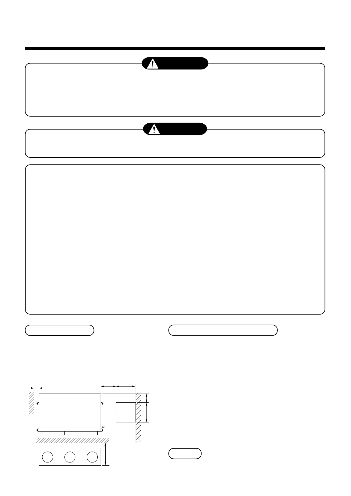
• When the outdoor unit is installed in an elev ated
position, be sure to secure its feet.
• There must be sufficient space for carrying in the
unit.
• A place where the drain water does not make an y
problem.
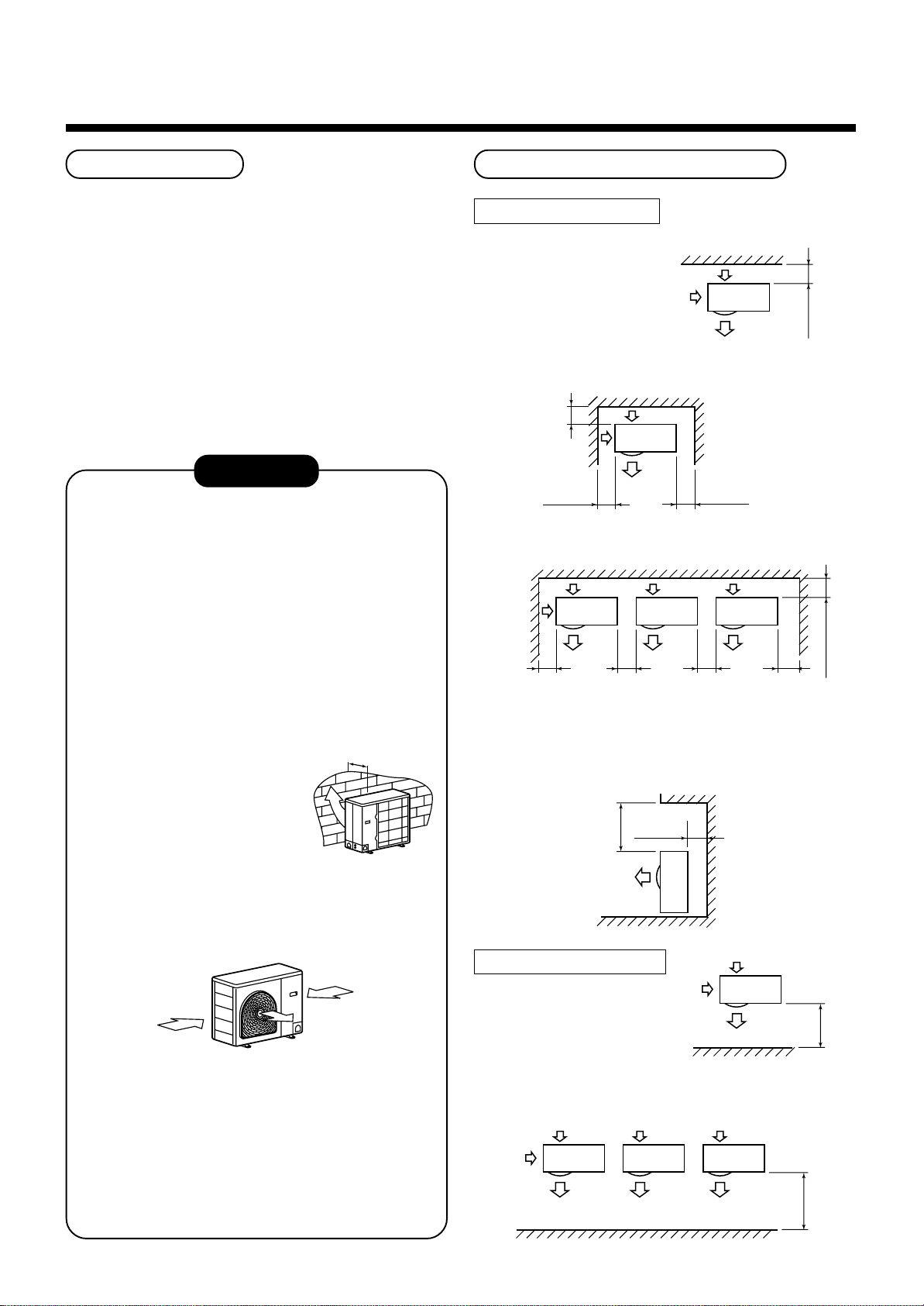
CAUTION
1. Install the outdoor unit at a place where dis-
charge air is not blocked.
2. When an outdoor unit is installed in a place that
is always exposed to a strong wind like a coast
or on a high storey of a building, secure a
normal fan operation by using a duct or a wind
shield.
3. When installing the outdoor unit in a place that is
constantly exposed to a strong wind such as the
upper stairs or rooftop of a building, apply the
windproof measures referring to the follo wing
examples.
1) Install the unit so that its
discharge port faces to the
wall of the building. Keep a
distance 500 mm or more
between the unit and the
wall surface .
500
Necessary Space for Installation
Obstacle at rear side
<Upper side is free>
1. Single unit installation
2. Obstacles at both right and left sides.
200
or more
150
or more
3. Serial installation of two or more units
150
or more
The height of the obstacle should be lower
than the height of the outdoor unit.
300
or more
<Obstacle also at the upper side>
The height of the
obstacle should be
lower than the height
of the outdoor unit.
300
or more
300
or more
150
300
or more
or more
200 or more
2) Supposing the wind direction during the
operation season of the air conditioner, install
the unit so that the discharge port is set at
right angle to the wind direction.
Strong
wind
Strong
wind
4. Installation in the following places may result in
some troubles. Do not install the unit in such
places below.
• A place full of machine oil.
• A place full of sulphuric gas.
• A place where high-frequency radio waves are
likely to be generated as from audio quipment,
welders, and medical equipment.
Obstacle at front side
<Upper side is free>
1. Single unitIn installation
2. Serial installation of two or more units
– 22 –
500
1000
or more
or more
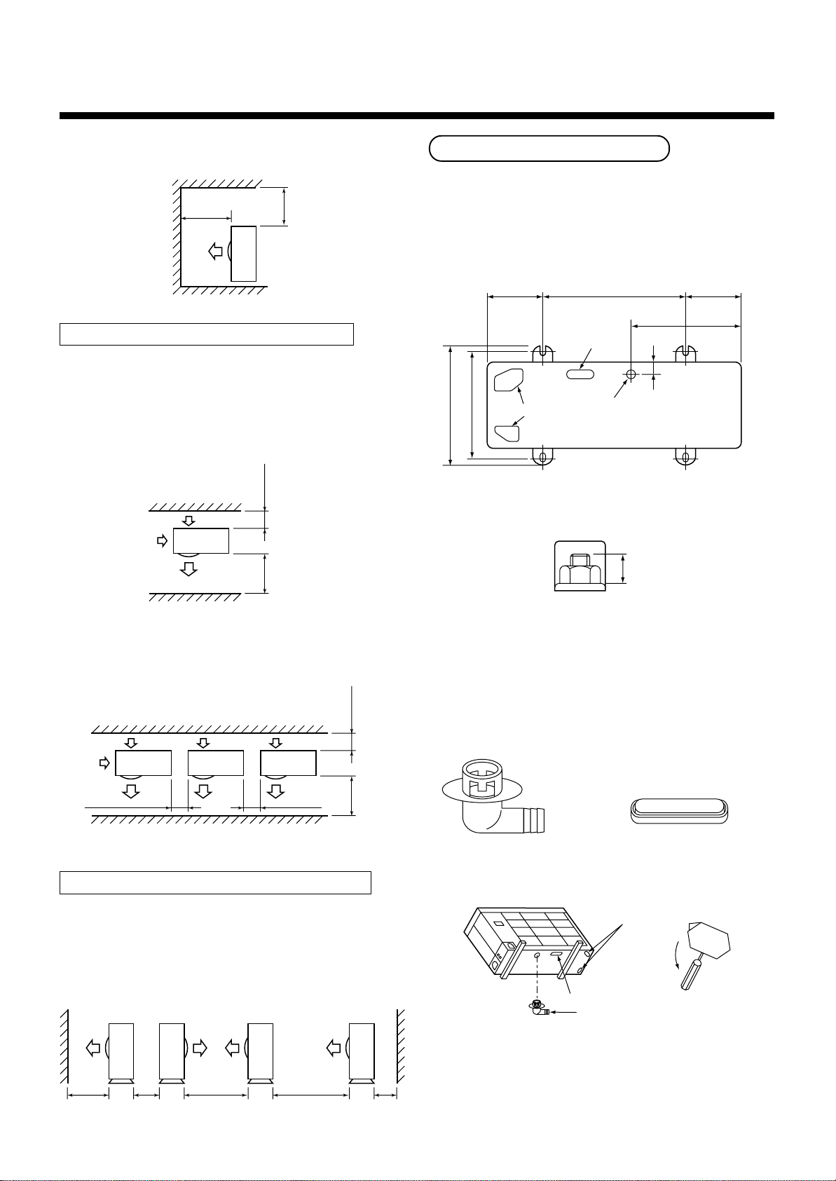
15 or less
3
SELECTION OF INSTALLATION
RAV -SP1100, 1400AT-E
RAV -SM1100, 1400AT-E
<Obstacle also at the upper side>
1000
or more
1000
or more
Obstacles at both front and rear sides
Open the upper side and both right and left sides.
The height of obstacle at both front and rear side,
should be lower than the height of the outdoor unit.
<Standard installation>
1. Single unit installation
150
or more
Installation of Outdoor Unit
• Before installation, check strength and horizontality of
the base so that abnormal sound does not generate.
• According to the following base diagram, fix the base
firmly with the anchor bolts.
(Anchor bolt, nut: M10 x 4 pairs)
600150 150
430
Drain hole
40
365
400
Knockout hole
Set the out margin of the anchor bolt to 15mm or less.
Drain nipple mounting hole
1000
or more
2. Serial installation of two or more units
200
or more
300
or more
300
or more
1000
or more
Serial installation at front and rear sides
Open the upper side and both right and left sides.
The height of obstacle at both front and rear sides
should be lower than the height of the outdoor unit.
<Standard installation>
• In case of drainning through the drain hose, attach
the following drain nipple and the waterproof rubber
cap, and use the drain hose (Inner diam.: 16mm) sold
on the market. And also seal the screws securely with
silicone material, etc. so that w ater does not drop
down. Some conditions may cause dewing or dripping of water.
Drain nipple Waterproof rubber cap
Knockout hole
Open
Waterproof rubber cap
Drain nipple
1000
or more
300
or more
1500
or more
2000
or more
200
or more
• When there is a possibility of freezing of drain at the
cold district or a snowfall area, be careful for drainage
ability of drain. The drainage ability increases when a
knockout hole on the base plate is opened. (Open the
knockout hole to outside using a screwdriver, etc.)
– 23 –
RAV -SP1100, 1400AT-E
RAV -SM1100, 1400AT-E
Optional Installation Parts
(Local Procure)
Parts name
Refrigerant piping
A
Liquid side : Ø9.5 mm
Gas side : Ø15.9 mm
Pipe insulating material
B
(polyethylene foam, 6 mm thick)
C
Putty, PVC tapes
Q’ty
Each one
1
Each one
Refrigerant Piping Connection
CAUTION
TAKE NOTICE THESE IMPORTANT
4 POINTS BELOW FOR PIPING WORK
1. Keep dust and moisture away from inside the
connecting pipes.
2. Tightly connect the connection between pipes
and the unit.
3. Evacuate the air in the connecting pipes using
VACUUM PUMP.
4. Check gas leak at connected points.
<Piping connection>
Liquid side Gas side
Outer diameter Thickness Outer diameter Thickness
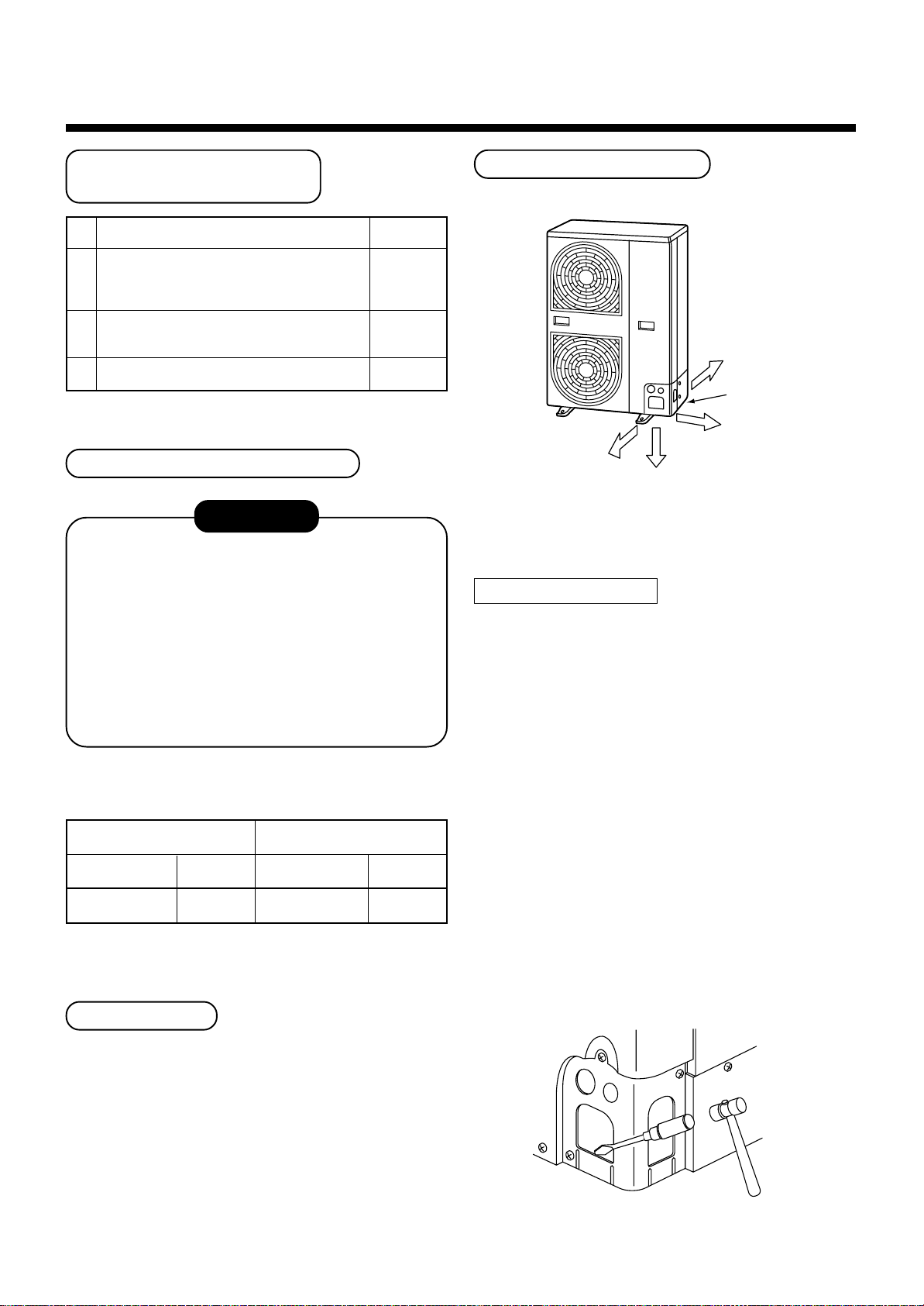
Knockout of Pipe Cover
Rear direction
Pipe cover
Side direction
Front direction
Down direction
Knockout procedure
• The indoor/outdoor connecting pipes can be connected to 4 directions.
Take off the knockout part of the pipe cover in which
pipes or wires pass through the base plate.
• As shown in the figure, do not remove the pipe cover
from the cabinet so that the knockout hole can be
easily punched. To knock out, it is easily taken off by
hands by punching a position at the lower side of 3
connected parts with screwdriver along the guide
line.
• After marking the knockout hole, remove the burr and
mount the attached protective bush and guard
material for pass-through part in order to protect
pipes and wires.
Ø9.5 0.8 Ø15.9 1.0
For Reference
If a heating operation would be continuously performed
for a long time under the condition that the outdoor
temperature is 0°C or lower, draining of defrosted water
may be difficult due to freezing of the bottom plate,
resulting in a trouble of the cabinet or fan.
It is recommended to procure an anti-freeze heater
locally for a safety installation of the air conditioner.
For details, contact the dealer.
After connecting the pipes, be sure to mount the pipe
cover. The pipe cover is easily mounted by cutting off
the slit at the lower part of the pipe cover.
– 24 –
3
SELECTION OF INSTALLATION
RAV -SP1100, 1400AT-E
RAV -SM1100, 1400AT-E
How to remove the front panel
1. Remove screws of the front panel.
2. Pull the front panel downward.
Removing the front panel, the electric parts appear at
the front side.
• The metal pipes are attachable to the piping holes.
If the size of the used power pipe does not match
with the hole, adjust the hole size to match with pipe
size.
• Be sure to fix the power cable and indoor/outdoor
connecting cable with bundling band sold on the
market so that they do not mak e contact with the
compressor and discharge pipe.
(Temperature of the compressor and discharge pipe
becomes high.)
4
REFRIGERANT PIPING
In order to avoid the force applied to on the connecting section, be sure to fix the cables to the cord
clamps provided on the pipe valve fixing plate and the
electric parts box.
Electric parts box
Terminal
plate
Cord clamp
Front panel
Piping
hole
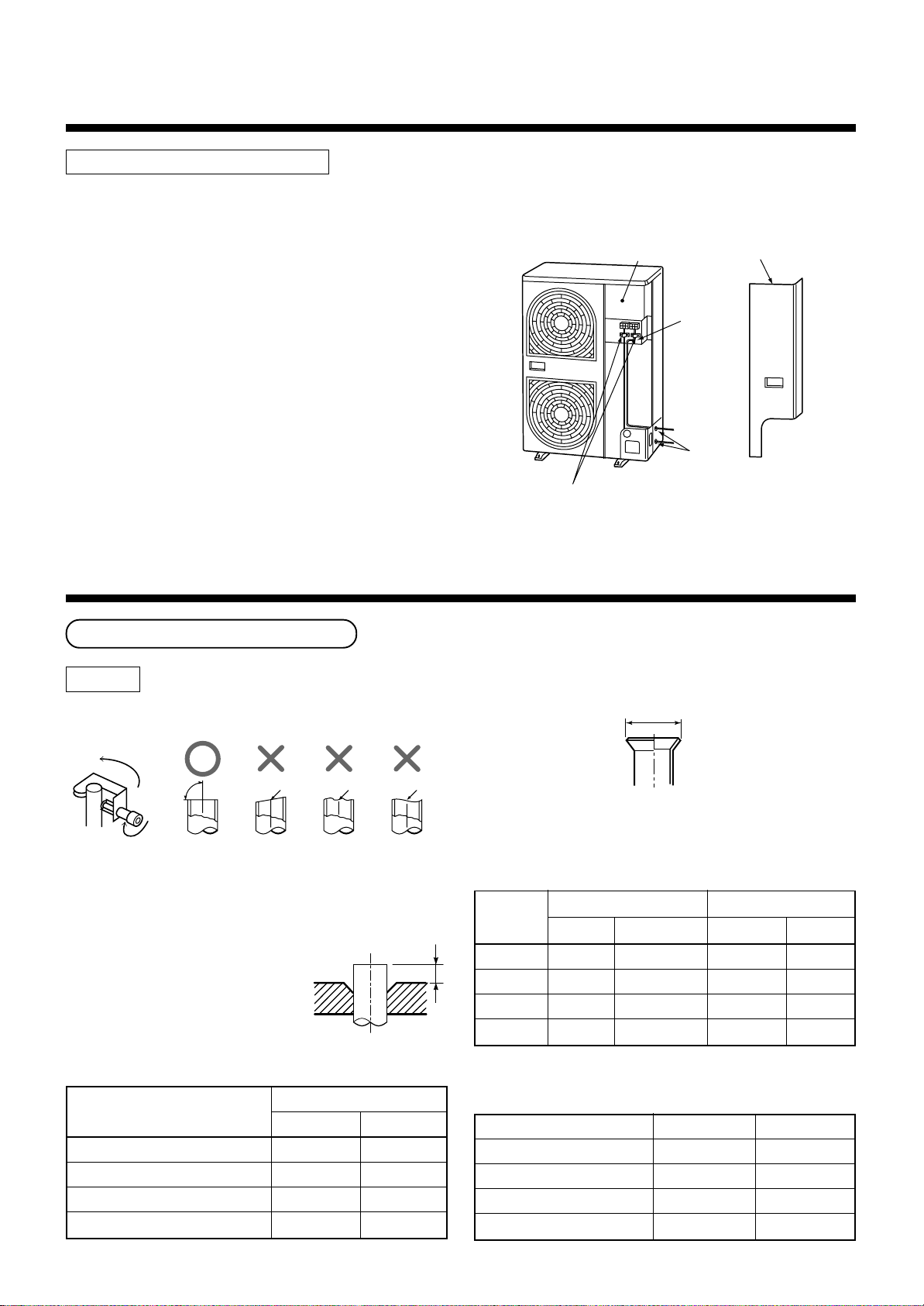
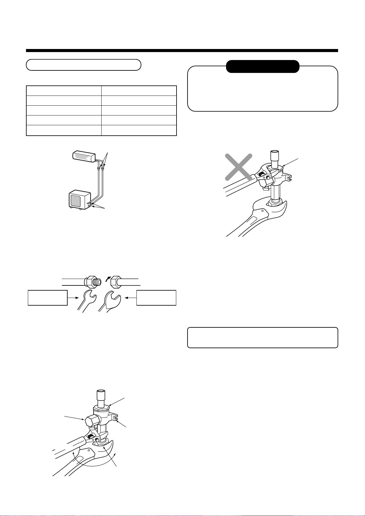
Pipe Forming/End Positioning
Flaring
1. Cut the pipe with a pipe cutter.
90˚
2. Insert a flare nut into the pipe, and flare the pipe.
As the flaring sizes of R410A differ from those of
refrigerant R22, the flare tools newly manufactured
for R410A are recommended.
Howe ver, the conv entional
tools can be used by adjusting
projection margin of the copper
pipe.
• Flaring size : A (Unit : mm)
Obliquity Roughness Warp
* In case of flaring for R410A with the conventional
flare tool, pull it out approx. 0.5 mm more than that of
R22 to adjust to the specified flare size. The copper
pipe gauge is useful for adjusting projection margin
size.
A
• Projection margin in flaring : B (Unit : mm)
Rigid (Clutch type)
B
Outer dia.
of copper
pipe
6.4
9.5
12.7
15.9
R410A tool used
R410A R22
0 to 0.5
0 to 0.5
0 to 0.5
0 to 0.5
(Same as left)
(Same as left)
(Same as left)
(Same as left)
Conventional tool used
R410A R22
1.0 to 1.5 0.5 to 1.0
1.0 to 1.5 0.5 to 1.0
1.0 to 1.5 0.5 to 1.0
1.0 to 1.5 0.5 to 1.0
Outer dia. of copper pipe
6.4
9.5
12.7
15.9
+0
A
- 0.4
R410A R22
9.1 9.0
13.2 13.0
16.6 16.2
19.7 19.4
Imperial (Wing nut type)
Outer dia. of copper pipe
6.4
9.5
12.7
15.9
– 25 –
R410A R22
1.5 to 2.0 1.0 to 1.5
1.5 to 2.0 1.0 to 1.5
2.0 to 2.5 1.5 to 2.0
2.0 to 2.5 1.5 to 2.0
4
REFRIGERANT PIPING
RAV -SP1100, 1400AT-E
RAV -SM1100, 1400AT-E
Tightening of Connecting Part
(Unit: N•m)
Outer dia. of copper pipe
6.4 mm (diam.)
9.5 mm (diam.)
12.7 mm (diam.)
15.9 mm (diam.)
Flare at
indoor unit side
• Align the centers of the connecting pipes and tighten
the flare nut strong as far as possib le with your
fingers.
Then fix the nut with a spanner and tighten it with
torque wrench as shown in the figure.
Tightening torque
14 to 18 (1.4 to 1.8 kgf•m)
33 to 42 (3.3 to 4.2 kgf•m)
50 to 62 (5.0 to 6.2 kgf•m)
68 to 82 (6.8 to 8.2 kgf•m)
Flare at
outdoor unit side
REQUIREMENT
1. Do not put the spanner on the cap. The valve
may be broken.
2. If applying excessiv e torque, the nut may be
broken according to some installation conditions.
• After the installation work, be sure to check gas leak
of connecting part of the pipes with nitrogen.
Cover
Half union or packed valve Flare nut
Externally
threaded side
Fix with spanner.
Tighten with torque wrench.
Internally
threaded side
• As shown in the figure, be sure to use a double
spanner to loosen or tighten the flare nut of the valve
at gas side. If using a single spanner, the nut cannot
be tightened with necessary tightening torque.
On the contrary, use a single spanner to loosen or
tighten the flare nut of the valve at liquid side.
Cover
Cap
Piping valve
Loosened
Tightened
• Pressure of R410A is higher than that of R22
(Approx. 1.6 times). Therefore, using a torque
wrench, tighten the flare pipe connecting sections
which connect the indoor/outdoor units at the specified tightening torque. Incomplete connections may
cause not only a gas leak, but also a trouble of the
refrigeration cycle.
Do not apply refrigerating machine oil to
the flared surface.
Flare nut
Valve at gas side
– 26 –
RAV -SP1100, 1400AT-E
RAV -SM1100, 1400AT-E
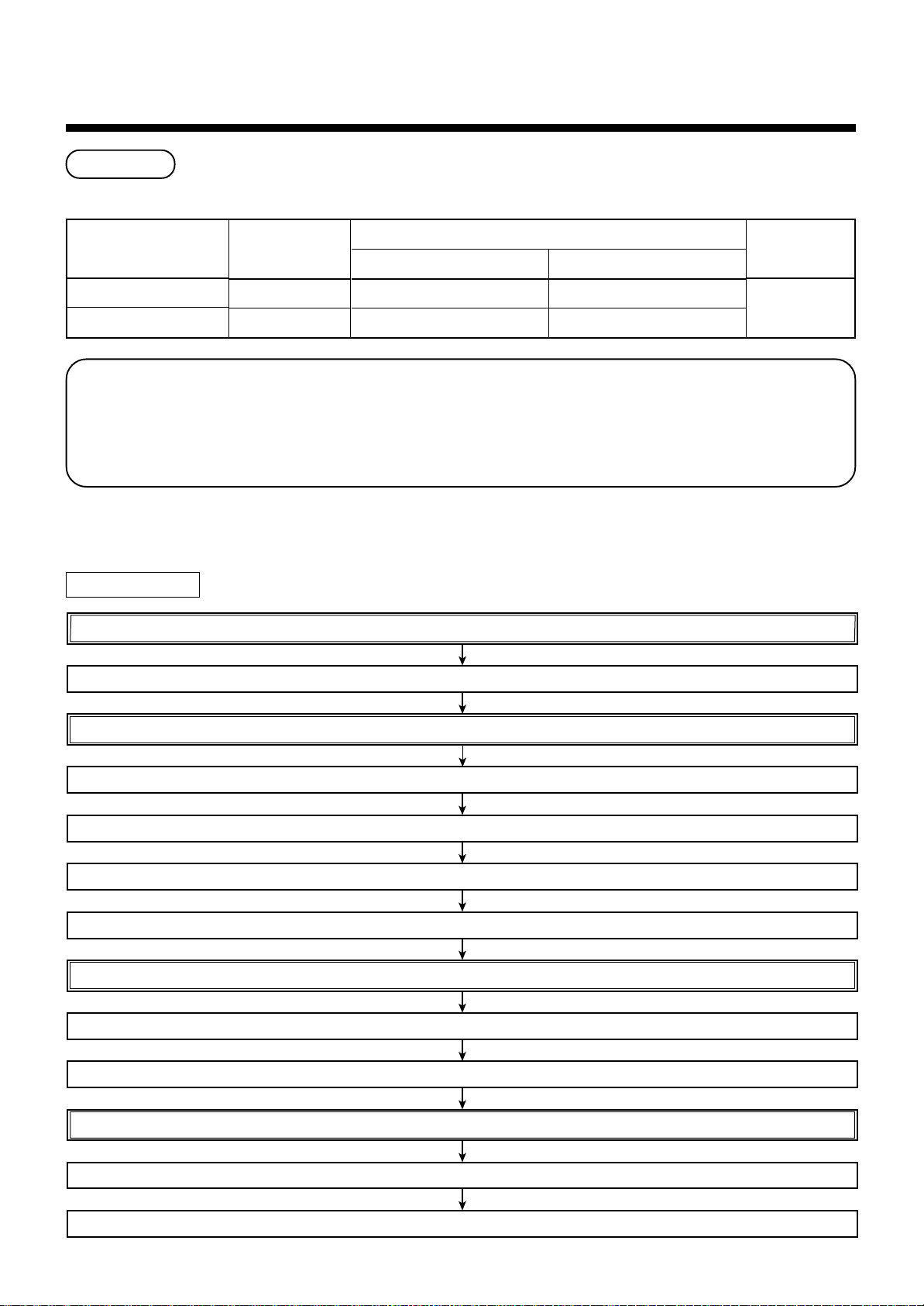
5
EVACUATING
Air Purge
This air conditioner can be installed up to the connecting pipe length and height difference in the following table.
Capacity rank
SM1100, SM1400 type
SP1100, SP1400 type
With respect to the preservation of terrestrial environment, adopt “Vacuum pump” for air purge (Evacuate air in
the connecting pipes) when installing the unit.
• Do not discharge the refrigerant gas to the atmosphere to preserve the terrestrial environment.
• Use a vacuum pump to discharge the air (nitrogen, etc.) remained in the set. If the air remains, the capacity
may decrease.
For the vacuum pump, be sure to use one with backflow preventer so that the oil in the pump does not backflow
into the pipe of the air conditioner when the pump stops. (If oil in the vacuum pump is put in an air conditioner
including R410A, it may cause trouble on the refrigeration cycle .)
Max. connecting
pipe length (m)
50
70
Outdoor unit at upper side Outdoor unit at lower side
Height difference (m)
30 15
30 15
Hexagonal
wrench size
4mm
Vacuum pump
As shown in the right figure, connect the charge hose after the manifold valve are closed completely.
Attach the connecting port of the charge hose with a projection to push the valve core (setting pin) to the charge port of the set.
Open handle Low fully.
Turn ON the vacuum pump (*1)
Loosen the flare nut of the packed valve (Gas side) a little to check the air passes through. (*2)
Tighten the flare nut again.
Execute vacuuming until the compound pressure gauge indicates –101kPa (–76cmHg). (*1)
Close handle Low completely.
Turn OFF the vacuum pump.
Leave the vacuum pump as it is for 1 or 2 minutes, and check the indicator of the compound pressure gauge does not return.
Open fully the valve stem or the valve handle. (First, at liquid side, then gas side)
Disconnect the charge hose from the charge port.
Tighten valve and caps of the charge port surely.
– 27 –
RAV -SP1100, 1400AT-E
RAV -SM1100, 1400AT-E
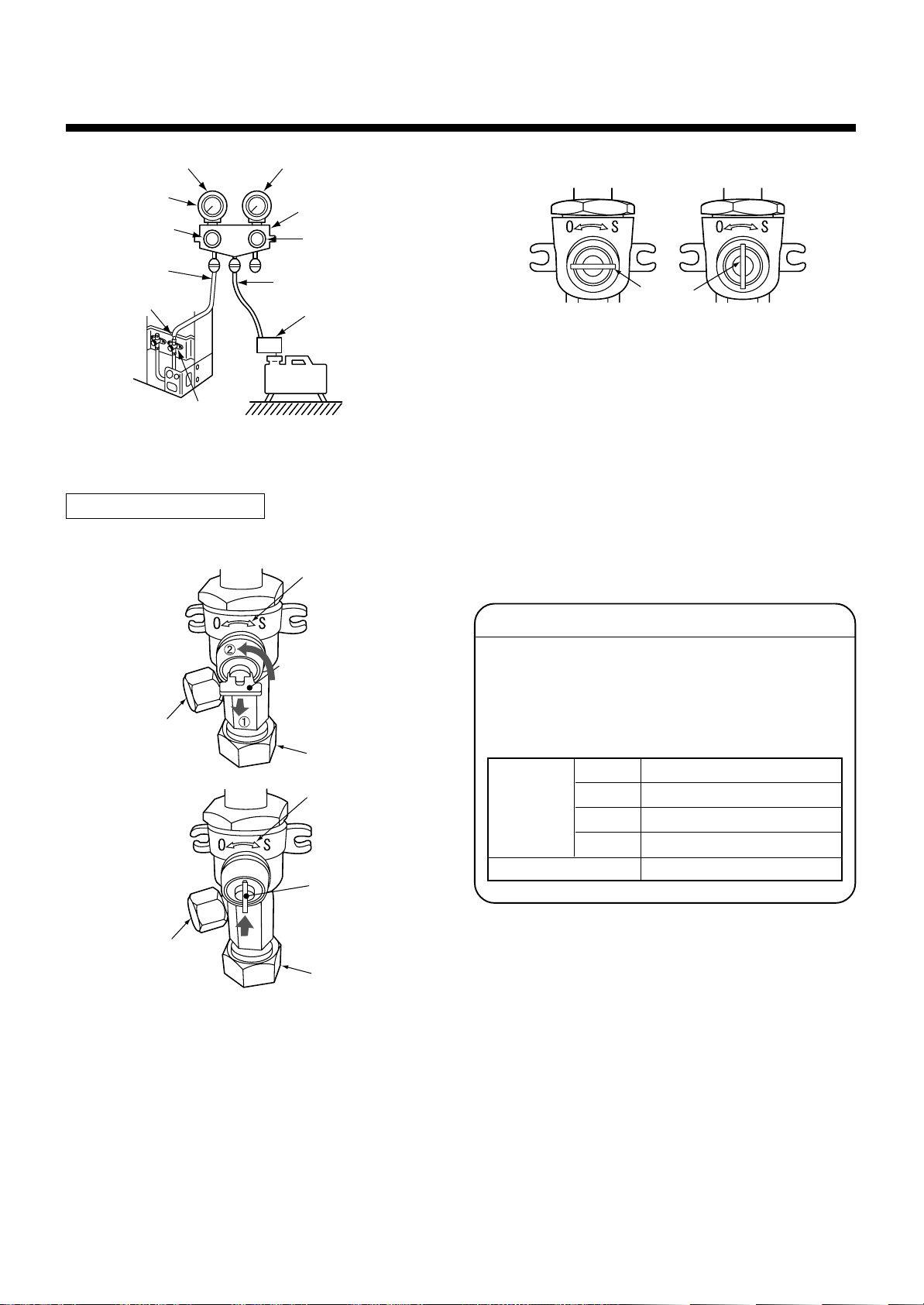
Compound pressure gauge
–101kPa
(–76cmHg)
Handle Lo
Charge hose
(For R410A only)
Service port
(Valve core (Setting pin))
Packed valve at gas side
How to open the valve
Pressure gauge
Manifold valve
Handle Hi
(Keep fully closed)
Charge hose
(For R410A only)
Vacuum pump adapter
for counter-flow prevention
(For R410A only)
Vacuum
pump
Valve unit
Handle position
Handle
Closed completely
Opened fully
*1. Use the vacuum pump, vacuum pump adapters,
and gauge manifold referring to the manuals
attached to each tool before using them. For the
vacuum pump, check oil is filled up to the specified
line of the oil gauge.
*2. While the air is purged, check again that the
connecting port of charge hose, which has a
projection to push the valve core, is firmly connected to the charge port.
Charge port
Charge port
Handle
Pull out the handle and
using cutting pliers, etc.
turn it counterclockwise
by 90˚. (Open fully)
Flare nut
Valve unit
Push in handle.
Flare nut
Valve handling precautions
• Open the valve stem or the handle until it strikes
the stopper. It is unnecessary to apply further
force.
• Securely tighten the cap with a torque wrench.
• Cap tightening torque
Valve siz e
Charge port
Ø6.4
Ø9.5
Ø12.7
Ø15.9
14 to 18N•m (1.4 to 1.8kgf•m)
33 to 42N•m (3.3 to 4.2kgf•m)
33 to 42N•m (3.3 to 4.2kgf•m)
20 to 25N•m (2.0 to 2.5kgf•m)
14 to 18N•m (1.4 to 1.8kgf•m)
– 28 –
RAV -SP1100, 1400AT-E
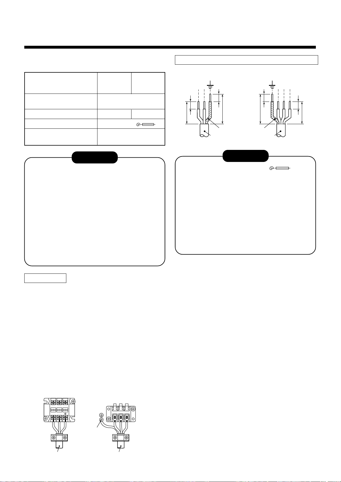
RAV -SM1100, 1400AT-E
6
For the air conditioner that has no power cable, connect
a power cable as mentioned belo w.
Power supply
Maximum running current
Installation fuse rating
Power cable
ELECTRICAL WORK
Model RAV-
SM1100AT-E SP1100AT-E
Single phase 50 Hz
22.0 A 22.8 A
25 A (D type )
H07 RN-F or 245 IEC 66
(2.5 mm
SM1400AT-E
SP1400AT-E
220 – 240 V
2
or more)
CAUTION
• Wrong wiring may cause a burn-out to some
electrical parts.
• Be sure to use the cord clamps attached to the
product.
• Do not damage or scratch the conductive core
and inner insulator of power and inter-connecting
cables when peeling them.
• Be sure to comply with local regulations of the
cable from outdoor unit to indoor unit.
(wire size and cabling method etc.)
• Use the power and Inter-connecting cables with
specified thickness, specified type and protective
devices required.
Stripping length power cord and connecting cabl e
LN
10 10
40 30
10 10
50 40
Earth line Earth line
Power cable
Connecting
cable
123
(mm)
CAUTION
• The installation fuse (25A D type ) must
be used for the power supply line of this air
conditioner.
• Incorrect/incomplete wiring might cause an
electrical fire or smoke.
• Prepare the exclusive power supply for the air
conditioner.
• This product can be connected to the mains.
Connection to the fixed wiring :
A switch which disconnects all poles and has a
contact separation of at least 3 mm must be
incorporated in the fixed wiring.
How to wire
1. Connect the connecting cable to the terminal as
identified with their respective numbers on the
terminal block of indoor and outdoor unit.
H07 RN-F or 245 IEC 66 (1.0 mm2 or more)
2. When connecting the connecting cable to the
outdoor unit terminal, prevent water coming in the
outdoor unit.
3. Insulate the unsheathed cords (conductors) with
electrical insulation tape. Process them so that they
do not touch any electrical or metal parts.
4. For inter connecting cable, do not use a wire jointed
to another on the way.
Use wires long enough to cover the entire length.
Power supply
terminal block
LN
Earth screw
To Indoor unit
terminal block
123
Connecting cablePower cable
– 29 –
RAV -SP1100, 1400AT-E
RAV -SM1100, 1400AT-E
7
FINAL INSTALLATION CHECKS
Check and Test Operation
For R410A, use the leak detector e xclusiv ely manufactured for HFC refrigerant (R410A, R134a, etc.).
The conventional leak detector for HCFC refrigerant (R22, etc.) cannot be used because its sensitivity for HFC
*
refrigerant lowers to approx. 1/40.
• Pressure of R410A is approx. 1.6 times higher than that of R22.
If installation work is incompletely finished, a gas leakage may occur when pressure rises during operation.
Therefore, be sure to test the piping connections for leakage.
• Check gas leakage at the flare nut connections, valve stem cap connections and service port cap fittings with a
leak detector or soap water.
CAUTION
When the remote controller is used for the first time, it accepts an operation approx. 5 minutes after the power
supply has been turned on.
It is not a trouble, b ut is because the setup of the remote controller is being checked.
For the second pow er-ON time and after, approx. 1 mun ute is required to start the operation by the remote controller .
Useful Functions
In addition to the code checking by remote controller of the indoor unit, troub les of the outdoor unit can be diagnosed by LED indications on the cycle control P.C. board of the outdoor unit. Utilize them for various checks.
For the check by remote controller of the indoor unit, refer to the Installation Manual of the indoor unit.
Before a check, confirm each bit of the DIP switch SW800 is set to OFF position.
LED indication and code checking
Cycle control P.C. board
LED indication
D800 ¡ : Red
¡ : Yellow
D801
¡ : Yellow
D802
¡ : Yellow
D803
¥ : Rapid flash
l : Go off
¡ : Go on
LED indication
D800 D801 D802 D803
¡
lll
ll
¡¡
l
l
¡¡¡
¡
l
l
¡¡
ll
¥ l
l ¥ l
¥¥
l
¥ l ¥
¡
ll
¡
l
¡
ll
ll
¡
l
¡¡
l
¡¡
ll
ll
¥
l
l
¡
l
¡
¡
l
¡
l
l
l
Self-Diagnosis by LED Indication
Cause
Heat exchanger sensor (TE) error
Suction sensor (TS) error
Discharge sensor (TD) error
High-pressure protection error
Outdoor temperature sensor (TO) error
DC outside fan error
Communication error between IPDU (Abnormal stop)
High-pressure release operation
Discharge temp. error
EEPROM error
Communication error between IPDU (No abnormal stop)
G-Tr short-circuit protection
Detect circuit error
Current sensor error
Comp. lock error
Comp. break down
– 30 –
7
FINAL INSTALLATION CHECKS
RAV -SP1100, 1400AT-E
RAV -SM1100, 1400AT-E
Installation/Servicing T ools
In the case of an air conditioner using R410A, in order to prevent any other refrigerant from being charged accidentally, service port diameter of the outdoor unit control valv e (3 way valve) has been changed. (1/2 UNF 20 threads
per inch)
• In order to increase the pressure resisting strength of the refrigerant piping flare processing diameter and size of
opposite side of flare nuts has been changed. (for copper pipes with nominal dimensions 1/2 and 5/8)
Changes in the product and components
New tools for R410A
New tools for R410A
Gauge manifold
Charge hose
Electronic balance
for refrigerant charging
Torque wrench
(nominal diam. 1/2, 5/8)
Flare tool
(clutch type)
Applicable to R22 model
××
×
××
××
×
××
¡
××
×
××
¡
Changes
As pressure is high, it is impossible to measure by means of conventional
gauge. In order to prevent any other refrigerant from being charged, each
port diameter is changed.
In order to increase pressure resisting strength, hose materials and port
size are changed (to 1/2 UNF 20 threads per inch).
When purchasing a charge hose, be sure to check the port size.
As pressure is high and gasification speed is fast, it is difficult to read the
indicated value by means of charging cylinder, as air bubbles occur.
The size of opposite sides of flare nuts have been increased. Incidentally,
a common wrench is used for nominal diameters 1/4 and 3/8.
By increasing the clamp bar’s receiving hole, strength of spring in the tool
has been improved.
Gauge for projection adjustment
Vacuum pump adapter
Gas leakage detector
• Incidentally, the “refrigerant cylinder” comes with the refrigerant designation (R410A) and protector coating in the
U,S. ’s ARI specified rose color (ARI color code: PMS 507).
• Also, the “charge port and packing for refrigerant cylinder” require 1/2 UNF 20 threads per inch corresponding to
the charge hose’s port size.
——
¡
××
×
××
Used when flare is made with using conventional flare tool.
Connected to the conventional vacuum pump. It is necessary to use an
adapter to prevent vacuum pump oil from flowing back to the charge hose.
The charge hose connecting part has two por ts-one for conventional
refrigerant (7/16 UNF 20 threads per inch) and one for R410A.
If the vacuum pump oil (mineral) mixes with R410A a sludge may occur
and damage the equipment.
Exclusive for HFC refrigerant.
– 31 –

INDOOR
CONTENTS
INSTALLATION MANUAL
4-Way Air Discharge Cassette Type
RAV-SP1100UT-E
RAV-SM560UT-E, RAV-SM800UT-E, RAV-SM1100UT-E, RAV-SM1400UT-E
Accessory parts and Parts to be procured locally ........76
1
PRECAUTIONS FOR SAFETY ...............................77
2
SELECTION OF INSTALLATION PLACE............... 79
3
DRAIN PIPING WORK ............................................84
4
REFRIGERANT PIPING..........................................86
5
EVACUATING ..........................................................87
6
ELECTRICAL WORK ..............................................89
7
TEST RUN ...............................................................92
8
TROUBLESHOOTING.............................................93
9
MAINTENANCE ......................................................94
Concealed Duct Type
RAV-SM560BT-E, RAV-SM800BT-E,
RAV-SM561BT-E, RAV-SM801BT-E, RAV-SM1101BT-E, RAV-SM1401BT-E
Accessory parts and Parts to be procured locally ........95
1
PRECAUTIONS FOR SAFETY ...............................96
2
SELECTION OF INSTALLATION PLACE............... 98
3
INSTALLATION OF INDOOR UNIT.........................99
4
AIR DUCTING WORK ...........................................103
5
DRAIN PIPING WORK ..........................................108
6
REFRIGERANT PIPING........................................110
7
EVACUATING ........................................................111
8
ELECTRICAL WORK ............................................113
9
TEST RUN .............................................................115
10
TROUBLESHOOTING...........................................116
11
Applicable Controls .............................................117
12
INST ALLA TION/SERVICING TOOLS....................120
13
MAINTENANCE ....................................................120
Under Ceiling Type
RAV-SM561CT-E, RAV-SM801CT-E, RAV-SM1101CT-E, RAV-SM1401CT-E
Accessory parts and Parts to be procured locally ......121
1
PRECAUTIONS FOR SAFETY .............................122
2
SELECTION OF INSTALLATION PLACE.............124
3
DRAIN PIPING WORK ..........................................129
4
REFRIGERANT PIPING AND EVACUATING .......131
5
ELECTRICAL WORK ............................................133
– 75 –
6
TEST RUN .............................................................136
7
TROUBLESHOOTING...........................................137
8
Applicable Controls .............................................138
9
INST ALLA TION/SERVICING TOOLS....................141
10
MAINTENANCE ....................................................141
RAV-SM560, 561, 800, 801BT-E
RAV-SM1101, 1401BT-E
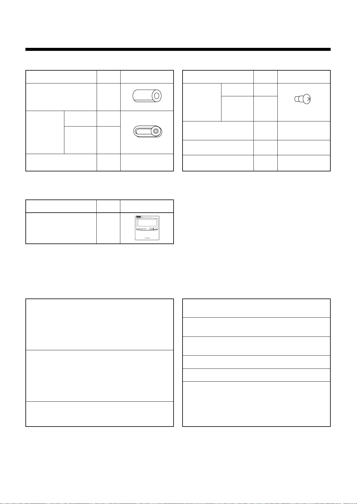
Accessory parts and Parts to be procured locally
r Accessory parts
Part name
Pipe insulator
561BT
Clamp for air
filter fixing
Washer for unit hung-up
801BT
1101BT
1401BT
<Separate sold parts>
Part name
Standard wired remote
controller
Q’ty
2
2
4
8
Q’ty
1
Shape
Shape
Part name
561BT
Clamp screw 801BT
1101BT
1401BT
Connecting cable for
High static pressure tap
Installation Manual
Owner’s Manual
Q’ty
2
4
1
1
Shape
(with pedestal)
r Parts to be procured locally
Connecting pipe (Liquid side)
(6.4mm (diam.), Nominal (diam.) 1/4” thick 0.8mm)
RAV-SM561BT, RAV-SM560AT
(9.52mm (diam.), Nominal (diam.) 3/8” thick 0.8mm)
RAV-SM801BT, RAV-SM800AT
RAV-SM1101BT, RAV-SM1100AT
RAV-SM1401BT, RAV-SM1400AT
Connecting pipe (Gas side)
(12.7mm (diam.), Nominal (diam.) 1/2” thick 0.8mm)
RAV-SM561BT, RAV-SM560AT
(15.9mm (diam.), Nominal (diam.) 5/8” thick 1.0mm)
RAV-SM801BT, RAV-SM800AT
RAV-SM1101BT, RAV-SM1100AT
RAV-SM1401BT, RAV-SM1400AT
Power supply cord
2.5mm² (H07RN-F or 245IEC66) (20m or less),
3.5mm² (AWG-12) (50m or less)
Connecting cable
H07RN-F or 245IEC66 (1.5mm² or more)
Thermal insulation for refrigerant pipe
(10mm or more, thermal insulating foam polyethylene)
Thermal insulation for drain pipe
(10mm or more, foam polyethylene)
Drain pipe (Outer 32mm (diam.)) (VP25)
Tapes
Grounding cable (2.0mm (diam.) or more)
– 95 –
RAV-SM560, 561, 800, 801BT-E
RAV-SM1101, 1401BT-E
1
• Ensure that all Local, National and International regulations are satisfied.
• Read this “PRECAUTIONS FOR SAFETY” carefully before Installation.
• The precautions described below include the important items regarding safety. Observe them without fail.
• After the installation work, perform a trial operation to check for any problem.
Follow the Owner’s Manual to explain how to use and maintain the unit to the customer.
• Turn off the main power supply switch (or breaker) before the unit maintenance.
• Ask the customer to keep the Installation Manual together with the Owner’s Manual.
PRECAUTIONS FOR SAFETY
CAUTION New Refrigerant Air Conditioner Installation
• THIS AIR CONDITIONER ADOPTS THE NEW HFC REFRIGERANT (R410A) WHICH DOES NOT
DESTROY OZONE LAYER.
The characteristics of R410A refrigerant are ; easy to absorb water, oxidizing membrane or oil, and its pressure
is approx. 1.6 times higher than that of refrigerant R22. Accompanied with the new refrigerant, refrigerating oil
has also been changed. Therefore, during installation work, be sure that water, dust, former refrigerant, or
refrigerating oil does not enter the refrigerating cycle.
To prevent charging an incorrect refrigerant and refrigerating oil, the sizes of connecting sections of charging
port of the main unit and installation tools are charged from those for the conventional refrigerant.
Accordingly the exclusive tools are required for the new refrigerant (R410A).
For connecting pipes, use new and clean piping designed for R410A, and please care so that water or dust does
not enter. Moreover, do not use the existing piping because there are problems with pressure-resistance force
and impurity in it.
CAUTION To Disconnect the Appliance from Main Power Supply.
This appliance must be connected to the main power supply by means of a switch with a contact separation of
at least 3 mm.
The installation fuse (25A D type ) must be used for the power supply line of this conditioner.
WARNINGS
• Ask an authorized dealer or qualified installation professional to install/maintain the air
conditioner.
Inappropriate installation may result in water leakage, electric shock or fire.
• Turn off the main power supply switch or breaker before attempting any electrical work.
Make sure all power switches are off. Failure to do so may cause electric shock.
• Connect the connecting cable correctly.
If the connecting cable is connected in a wrong way, electric parts may be damaged.
• When moving the air conditioner for the installation into another place, be very careful not
to enter any gaseous matter other than the specified refrigerant into the refrigeration cycle.
If air or any other gas is mixed in the refrigerant, the gas pressure in the refrigeration cycle becomes
abnormally high and it may resultingly causes pipe burst and injuries on persons.
• Do not modify this unit by removing any of the safety guards or by by-passing any of the
safety interlock switches.
• Exposure of unit to water or other moisture before installation may cause a short-circuit of
electrical parts.
Do not store it in a wet basement or expose to rain or water.
– 96 –

RAV-SM560, 561, 800, 801BT-E
RAV-SM1101, 1401BT-E
• After unpacking the unit, examine it carefully if there are possible damage.
• Do not install in a place that might increase the vibration of the unit.
• To avoid personal injury (with sharp edges), be careful when handling parts.
• Perform installation work properly according to the Installation Manual.
Inappropriate installation may result in water leakage, electric shock or fire.
• When the air conditioner is installed in a small room, provide appropriate measures to
ensure that the concentration of refrigerant leakage occur in the room does not exceed the
critical level.
• Install the air conditioner securely in a location where the base can sustain the weight
adequately.
• Perform the specified installation work to guard against an earthquake.
If the air conditioner is not installed appropriately, accidents may occur due to the falling unit.
• If refrigerant gas has leaked during the installation work, ventilate the room immediately.
If the leaked refrigerant gas comes in contact with fire, noxious gas may generate.
• After the installation work, confirm that refrigerant gas does not leak.
If refrigerant gas leaks into the room and flows near a fire source, such as a cooking range, noxious gas might
generate.
• Electrical work must be performed by a qualified electrician in accordance with the
Installation Manual. Make sure the air conditioner uses an exclusive power supply.
An insufficient power supply capacity or inappropriate installation may cause fire.
• Use the specified cables for wiring connect the terminals securely fix. To prevent external
forces applied to the terminals from affecting the terminals.
• Conform to the regulations of the local electric company when wiring the power supply.
Inappropriate grounding may cause electric shock.
• Do not install the air conditioner in a location subject to a risk of exposure to a combustible
gas.
If a combustible gas leaks, and stays around the unit, a fire may occur.
– 97 –
RAV-SM560, 561, 800, 801BT-E
RAV-SM1101, 1401BT-E
2
SELECTION OF INSTALLATION PLACE
WARNING
• Install the air conditioner at enough strong place to withstand the weight of the unit.
If the strength is not enough, the unit may fall down resulting in injury.
• Install the air conditioner at a height 2.5m or more from the floor.
If you insert your hands or others directly into the unit while the air conditioner operates, it is dangerous
because you may contact with revolving fan or active electricity.
CAUTION
• Do not install the air conditioner in a location subject to a risk of exposure to a combustible gas.
If a combustible gas leaks and stays around the unit, a fire may occur.
Upon approval of the customer, install the air conditioner in a place that satisfies the following conditions.
• Place where the unit can be installed horizontally.
• In the process after removing the ceiling panel, it important to reinforce the groundwork (framework) and keep
a level correctly of the existing ceiling to prevent vibration of the ceiling panel.
• Place where a sufficient servicing space can be ensured for safety maintenance and check.
• Place where drained water will not cause any problem.
Avoid installing in the following places.
• Place exposed to air with high salt content (seaside area), or place exposed to large quantities of sulfide gas
(hot spring). (Should the unit be used in these places, special protective measures are needed.)
• Place exposed to oil, vapor, oil smoke or corrosive gas.
• Place where organic solvent is used nearby.
• Place close to a machine generating high frequency.
• Place where the discharged air blows directly into the window of the neighboring house. (For outdoor unit)
• Place where noise of the outdoor unit is easily transmitted.
(When installing the air conditioner on the boundary with the neighbor, pay due attention to the level of noise.)
• Place with poor ventilation. (Before air ducting work, check whether value of air volume, static pressure and
duct resistance are correct.)
Installation space
Secure the space required to installation
and servicing.
100 for service space
Refrigerant piping
Drain piping
100 or more
Maintenance etc.
Check/service
opening panel
420
or more
450
200
450
Selection of installation place
In case of continued operation of the indoor unit under highhumidity conditions as described below, dew may condense
and water may drop.
Especially, high-humidity atmosphere (dew point temperature :
23°C or more) may generate dew inside the ceiling.
1. Unit is installed inside the ceiling with slated roof.
2. Unit is installed at a location using inside of the ceiling as
fresh air take-in path.
3. Kitchen
If installing a unit at such place, adhere insulating material
(glass wool, etc.) additionally over all the positions of the
indoor unit which come to contact with high-humidity
atmosphere.
Advice
Set a check service opening panel at right side of the unit
(size: 450 x 450mm) for piping, maintenance, and servicing.
– 98 –
RAV-SM560, 561, 800, 801BT-E
RAV-SM1101, 1401BT-E
3
INSTALLATION OF INDOOR UNIT
WARNING
Install the air conditioner certainly at a place to sufficiently withstand the weight.
If the strength is insufficient, the unit may fall down resulting in human injury.
Perform a specified installation work to guard against an earthquake.
An incomplete installation can cause accidents by the units falling and dropping.
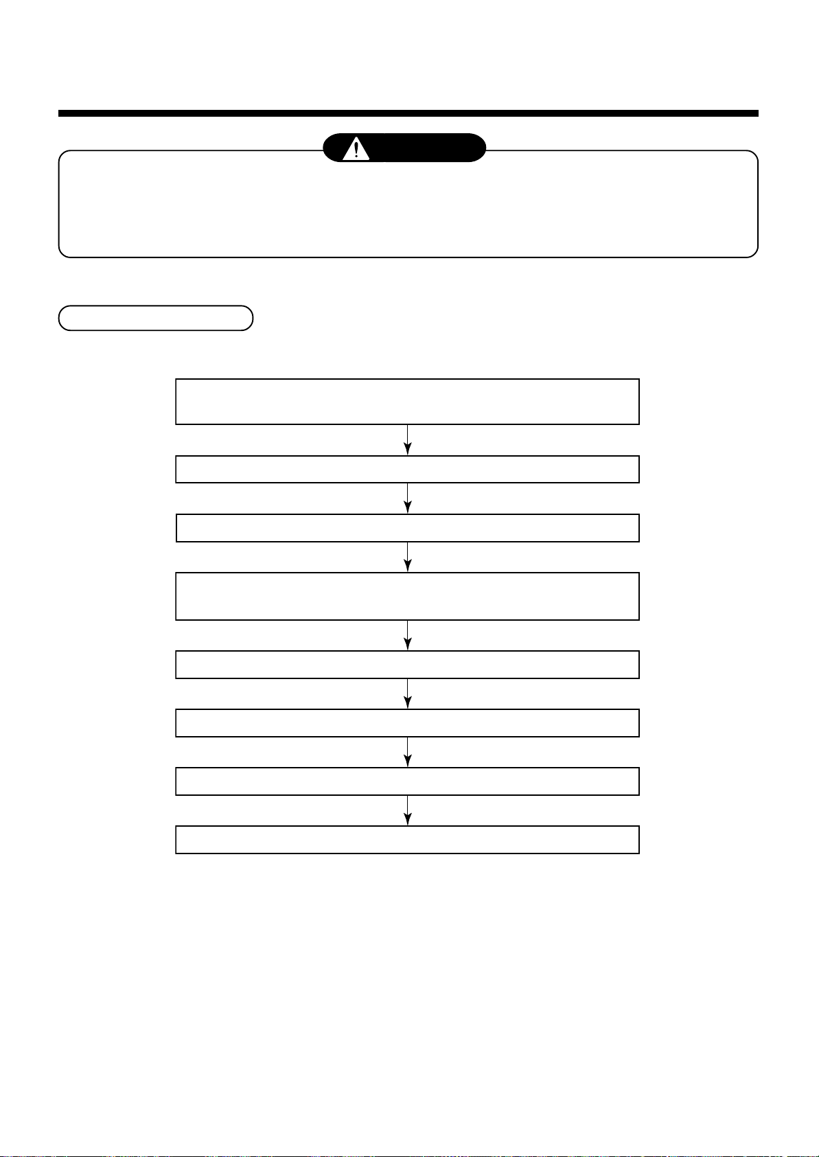
Installation procedure
1. Lay drain pipes, refrigerant pipes, and connecting cables behind wall
or ceiling concurrently with supply/drain water work and piping work.
2. Install the mounting frames of supply/return air panels
3. Position the refrigerant and drain pipes
4. Install the indoor unit
• Preparation for installation • Setting/fixing of indoor unit
5. Connect cables and pipes
6. Install supply/return air panels
7. Mount thermal insulation
8. Mount check port
– 99 –
RAV-SM560, 561, 800, 801BT-E
RAV-SM1101, 1401BT-E
3
INSTALLATION OF INDOOR UNIT
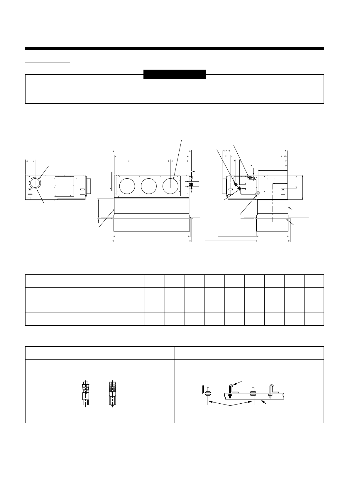
External view
REQUIREMENT
The hanging bolt pitch on horizontal direction (B) is not halved at center with the ceiling opening size.
Therefore, check the relational position in the following figure.
129
110
Knock-out hole Ø125
(Air take-in port)
6-Ø4 Tapping screw undersized
hole Ø160
• Dimension
RAV-SM561BT
Drain pipe connecting port
for vinyl chloride pipe
(Inner dia. 32, VP. 25)
Main unit dimension 800
75
Hanging bolt pitch 700
50
131
50
Ceiling open size 470
41
638
498
243
Panel C.L
393
410
196
5941
174
Suction port
flange
(Separate sold)
Suction port
panel
(Separate sold)
60~260
9
Suction port
canvas
(Separate sold)
Discharge port flange
N-Ø200
Hanging bolt pitch B
Main unit dimension A
J = M x K H
C
Ceiling open size D
Panel external dimension E
Refrigerant pipe
connecting port
(Gas side ØF)
Hanging bolt
4-M10 screw
(Arranged
locally)
44
49
Refrigerant pipe
connecting port
(Liquid side ØG)
Ø26 Power supply,
remote controller
cable take-out port
Panel external dimension 500
ABCDEFGHJKMN
700 766 690 750 780 12.7 6.4 252 280 280 1 2
320
RAV-SM801BT
RAV-SM1101, 1401BT
1000 1066 990 1050 1080 15.9 9.5 252 580 290 2 3
1350 1416 1340 1400 1430 15.9 9.5 252 930 310 2 4
In case of concrete slab
A hole-in-anchor, a hole-in-plug, or a hole-in-bolt is used.
In case of steel structure
Angle is used as it is, or a support angle is newly set.
Hanger bolt
Hanging bolt
Support angle
– 100 –
RAV-SM560, 561, 800, 801BT-E
RAV-SM1101, 1401BT-E
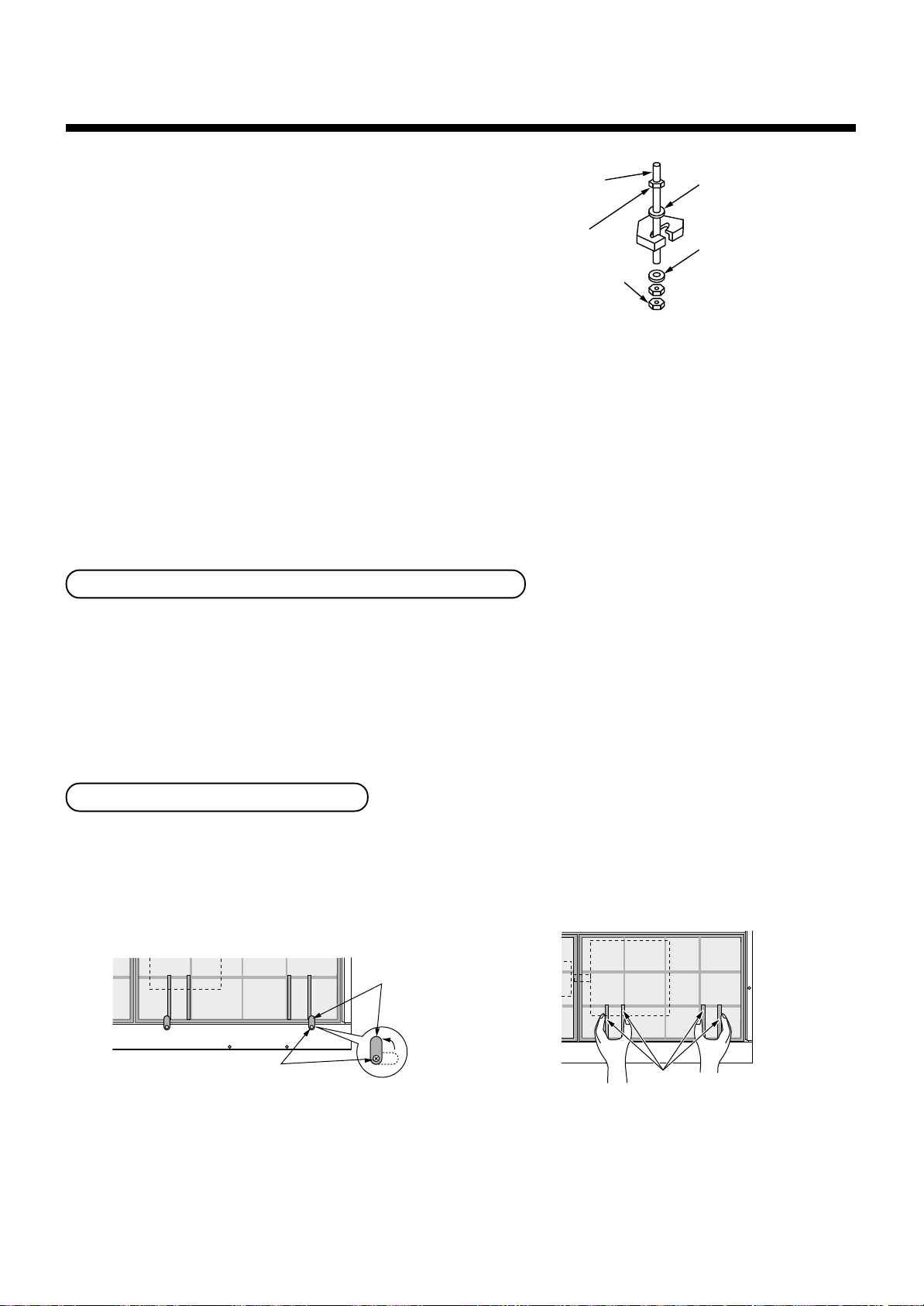
1. Hanging down of indoor unit
Refer to installation figures of hanging material and
hanging bolt.
• Adjustment of hanging bolt length and nut
position
Adjust hanging bolt length and nut position as
shown in the figure before hanging down the
Hanging bolt
(W3/8 or M10)
Nut
(W3/8 or M10)
Nut
(W3/8 or M10)
1)
M10 flat washer
(Accessory)
2)
M10 flat washer
(Accessory)
indoor unit.
• Using the level vial, etc., set the horizontal level
of the main unit within 5mm.
1) Required those other than M10 flat washer at site.
2) To prevent falling-off of bolt (safety), be sure to set
it just under the hanging bracket as shown in the
figure.
Considering pipe/wire connecting work inside the ceiling after the indoor unit has been hanged, select an installation
place and determine piping direction.
• If the ceiling has been already set, prepare refrigerant pipe, drain pipe, connecting wire, switch panel cord, etc. at
the place where pipe and wire are connected before hanging the main unit.
Installation of remote controller (Sold separately)
For installation of a remote controller, follow the Installation Manual attached to the remote controller.
• Do not install the remote controller at a place exposed to direct sunlight or near the stove.
• Install a remote controller after operating it and confirming that the indoor unit surely receives a signal.
[Wireless type]
• Install a remote controller apart from the TV or stereo device, otherwise image disturbance or noise may generate.
[Wireless type]
Mounting of clamp (Accessory)
In order to avoid falling of the air filter, be sure to mount the attached clamps with stepped screws.
(561BT : 2, 801BT to 1401BT : 4)
• Clamp mounting • Removal of air filter
Clamp
Stepped screw
Pull out filter downward
while holding the frames.
– 101 –
Channel
Supply chamber
Supply grille
Supplying
Supplying
Returning
Return air grille
Indoor unit
200mm (diam.)
round duct
3
INSTALLATION OF INDOOR UNIT
Concealed duct type
NOTE:
• Recommended supplying grille size 400 cm² each or more
RAV-SM560, 561, 800, 801BT-E
RAV-SM1101, 1401BT-E
Ledge ceiling concealed duct type
Indoor unit
Return air grille
Returning
Quality of supplying grilles
SM561BT
SM801BT
SM1101BT
SM1401BT
Restriction to installation
1. Installation clearance
• As shown in the figure, keep clearance around the indoor unit.
2
3
4
4
NOTE:
• Opening area of the return grille should be larger than
the one for suction port (Air filter) of the indoor unit.
Supplying
Supply
chamber
200mm (diam.)
round duct
Supply grille
Supplying
Inner ceiling
100mm or more
100mm
or more
– 102 –
100mm
or more
300mm
or more

RAV-SM560, 561, 800, 801BT-E
RAV-SM1101, 1401BT-E
4
AIR DUCTING WORK
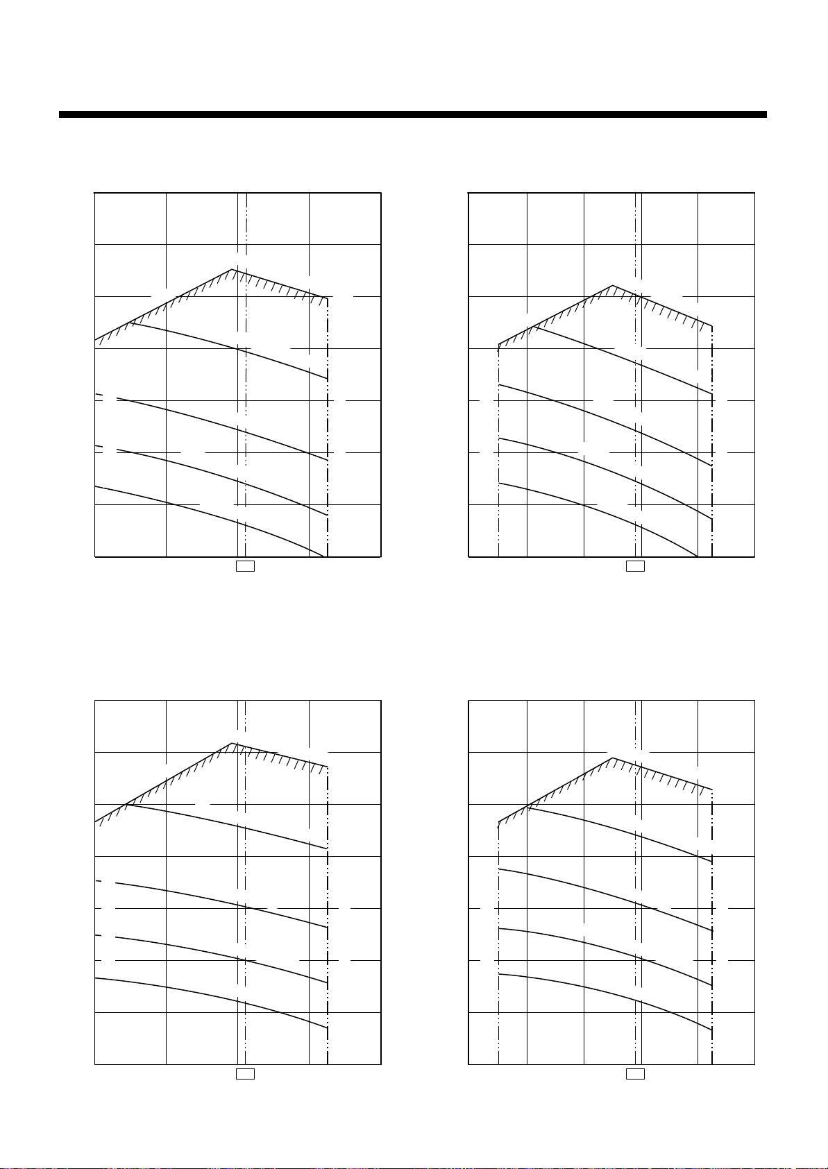
Static pressure characteristics of each model
Fig. 1 RAV-SM561BT (Round duct) Fig. 3 RAV-SM801BT (Round duct)
140
120
100
Usable limit
80
60
Static pressure (Pa)
40
Air volume limit (Min.)
20
Standard air volume 780m³/h
High static pressure 2H tap
High static pressure 1H tap
Standard H tap
Low static pressure H tap
Standard L tap
Static pressure (Pa)
Air volume limit (Max.)
140
120
100
80
60
40
20
Usable limit
Low static pressure H tap
Air volume limit (Min.)
Standard air volume 1140m³/h
High static pressure 2H tap
High static pressure 1H tap
Standard H tap
Standard L tap
Air volume limit (Max.)
0
500 700 780 900
Air volume m³/h
Fig. 2 RAV-SM561BT (Square duct)
140
120
108
100
80
60
Static pressure (Pa)
40
20
Usable limit
Air volume limit (Min.)
Standard air volume 780m³/h
High static pressure 2H tap
High static pressure 1H tap
Standard H tap
Low static pressure H tap
Standard L tap
Air volume limit (Max.)
0
800
1000
Air volume m³/h
Fig. 4 RAV-SM801BT (Square duct)
140
120
100
80
60
Static pressure (Pa)
40
20
Usable limit
Air volume limit (Min.)
Standard air volume 1140m³/h
High static pressure 2H tap
High static pressure 1H tap
Standard H tap
Low static pressure H tap
Standard L tap
12001140 1300
Air volume limit (Max.)
0
500 700 780 900
Air volume m³/h
– 103 –
0
800
1000
Air volume m³/h
12001140 1300
RAV-SM560, 561, 800, 801BT-E
RAV-SM1101, 1401BT-E
4
AIR DUCTING WORK
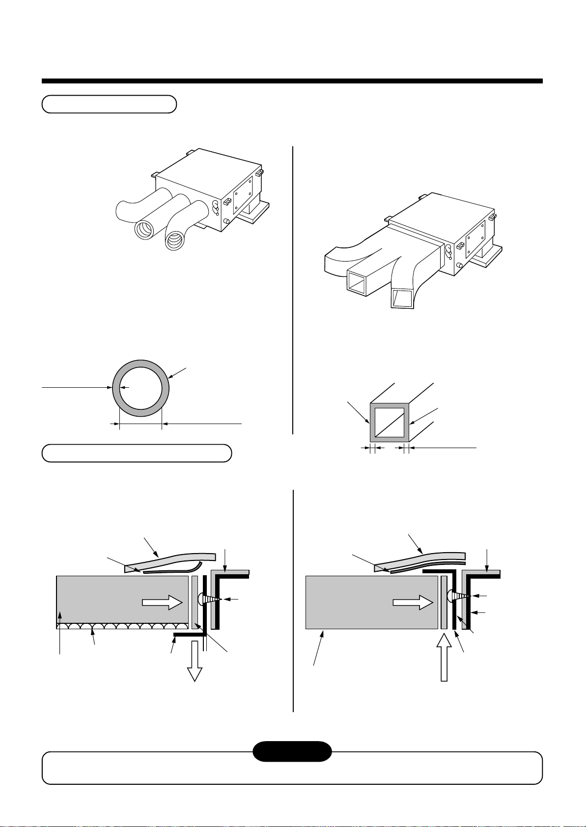
Fig. 5 RAV-SM1101BT (Round duct) Fig. 7 RAV-SM1401BT (Round duct)
140
120
Standard air volume 1620m³/h
140
120
Standard air volume 1980m³/h
High static pressure 2H tap
High static pressure 2H tap
100
100
Usable limit
High static pressure 1H tap
80
60
Standard H tap
Static pressure (Pa)
40
Air volume limit (Min.)
20
0
1200
Low static pressure H tap
Standard L tap
1620
Air volume limit (Max.)
2000
80
60
Static pressure (Pa)
40
20
0
1200 1800
Air volume m³/h
Usable limit
Air volume limit (Min.)
High static pressure 1H tap
Standard H tap
Low static pressure H tap
Standard L tap
1980
Air volume m³/h
Air volume limit (Max.)
2200 2400
Fig. 6 RAV-SM1101BT (Square duct) Fig. 8 RAV-SM1401BT (Square duct)
140
Standard air volume 1620m³/h
140
High static pressure 2H tap
120
120
Usable limit
100
80
High static pressure 1H tap
100
80
Usable limit
Standard H tap
60
Static pressure (Pa)
40
Air volume limit (Min.)
Low static pressure H tap
Air volume limit (Max.)
Standard L tap
20
60
Static pressure (Pa)
40
Air volume limit (Min.)
20
Standard air volume 1980m³/h
High static pressure 2H tap
High static pressure 1H tap
Standard H tap
Low static pressure H tap
Standard L tap
Air volume limit (Max.)
0
1200
1620
Air volume m³/h
2000
– 104 –
0
1200 1800
Air volume hm³/h
1980
2200 2400
RAV-SM560, 561, 800, 801BT-E
Fit to the arrow w
Fit to the arrow w
RAV-SM1101, 1401BT-E
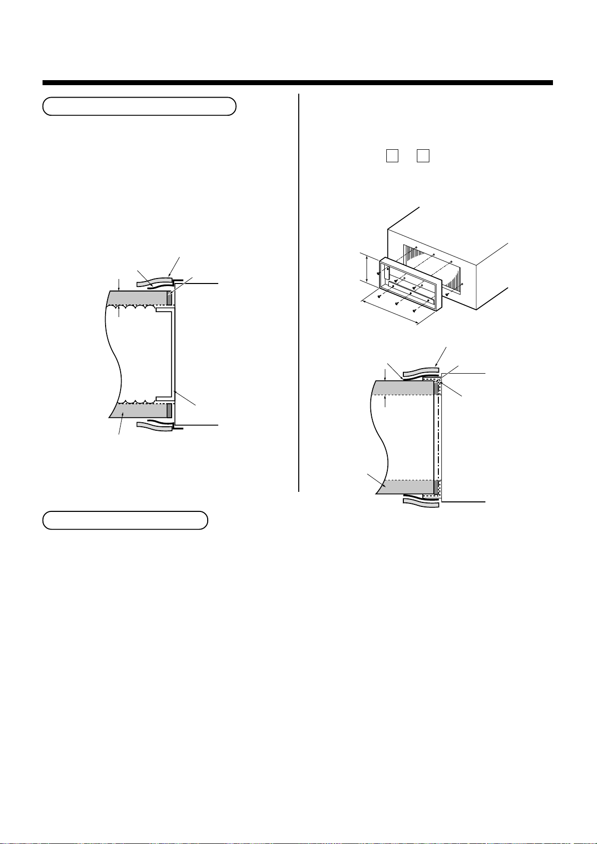
Installation reference (Example for RAV-SM801BT model)
The air supply ducting work is classified in two ways, one is branched by the round ducts, and the other is branched
by the square ducts. (Be sure to divide the air supply duct into three or more branches.)
<Round duct>
In case of the round duct, use the thermal insulator of
thickness 25mm or more and inner diameter 150mm
or more to the duct board.
(If the inner diameter is not enough, resistance
increase, as the result, air does not flow smoothly and
loss of the static pressure increases.) For the thermal
insulator, use high-density glass wool of 24kg/m3 or
equivalent.
Density of thermal
insulator (glass wool) is
25mm or more
24 kg/m³ or equivalent.
Ø150mm or more
<Square duct> (Reference for square duct)
When using the square duct, change the type of the air
supply flange from round type to square flange at the
local site.
In case of the square duct, apply the thermal insulator
of thickness 25mm or more to the duct board. For the
thermal insulator, use high-density glass wool of
weight 64kg/m3.
Duct board
Density of thermal
insulator (glass wool) is
64 kg/m³ or equivalent.
Connecting method of the duct
1. Supply air side
<Round duct> <Square duct>
Thermal insulator
with sticking material
(50mm-width, 6mm-thickness)
Aluminum tape
(Seal : 50mm-width)
Fit to the arro
Fit to the arrow
direction by pushing.
direction by pushing.
Thermal insulator
25mm-thickness,
( )
24kg/m³ or equivalent
Round duct
Fit the seal/thermal insulator (25mm-width, 6mm-thickness)
by pushing to the arrow direction so that no gap can be
found between the flange and the round duct.
Fig. 2 (a)
Thermal insulator
at indoor unit side
Stuck already at
( )
shipment from the factory
Flange
Seal/thermal insulator
with sticking material
(25mm-width, 6mm (t))
Screws
(6 pieces)
Aluminum tape
(Seal : 50mm-width)
Fit to the arrow
Fit to the arro
direction by pushing.
direction by pushing.
Square duct board
25mm-thickness,
( )
64kg/m³ or equivalent
25mm or more
Thermal insulator with
sticking material
(50mm-width, 6mm (t))
Attach by pushing to
the arrow direction.
(Outside corner direction)
Fig. 2 (b)
Thermal insulator
at indoor unit side
Stuck already at
( )
shipment from the factory
Screws
(6 pieces)
Indoor unit side
Flange
(procured locally)
Seal/thermal insulator
with sticking material
(25mm-width, 6mm (t))
CAUTION
Incomplete thermal insulation of the supply air flange and sealing may cause dew drops.
– 105 –
4
AIR DUCTING WORK
RAV-SM560, 561, 800, 801BT-E
RAV-SM1101, 1401BT-E
Connecting method of the duct
1. Supply air side
<Round duct>
1. Make the round duct according to inner dimension
of the flange
Use a glass wool board with inside/outside finishing
25mm-thickness and 24kg/m³-density.
2. Connect the flange and each type of duct. (Fig. 1)
Thermal insulator (50mm (w), 6mm (t))
Aluminum tape
(50mm-width)
25mm
Seal
Thermal insulator :
( )
25mm (w), 6mm (t)
Indoor unit
End
<Square duct>
1. Using 6 screws, mount the flange to the supply air
port of the indoor unit. (Fig. 2)
2. Make the square duct according to inner dimension
of the flange A x B .
Use a glass wool board with inside/outside finishing
25mm-thickness and 24kg/m³-density.
3. Connect the flange and each type of duct. (Fig. 3)
B
A
Fig. 2
Thermal insulator (50mm (w), 6mm (t))
Aluminum tape
(50mm-width)
25mm
Seal
Thermal insulator :
( )
25mm (w), 6mm (t)
End
Round duct board
Thermal insulator
(25mm thickness, 24kg/m³ or equivalent)
Fig. 1
Points at installation work
Square
duct board
(25mm)
Indoor unit
Fig. 3
n General cautions
1. Considering installation places of indoor unit supply chamber, structure of the building and determine the duct
path.
2. In order to utilize the static pressure characteristics of the air supply in the indoor unit, design the duct branching
having the large size of the air supply chamber or setting distance to the first branch as long as possible
(Min. : 200mm or longer) so that an even air volume can be obtained.
Especially, when branching just after air supply of the indoor unit, air concentrates at the center part and is
difficult to flow to the ducts at both sides.
3. Connect each connecting section surely, and apply sufficient thermal insulation.
In this model of which the duct is branched in the ceiling, compared with the model for ordinary houses, the high
temperature generates on the periphery in the cooling time (Especially, at attic and etc.), temperature difference
increases between the supply air and outside of the duct, and dewing may occur.
Dewing on the surface of the thermal insulator covering the metal connecting section or leaking portion of the
cooled air may cause a trouble such as water drops.
4. Thermal insulation of screwing sections is necessary.
Prevent dewing by applying thermal insulation to 6 screws those fix the duct flange of the air supply chamber.
• For duct parts, the flexible branch duct (thermal insulation, 25mm or more thickness) is recommended.
• Adjust the duct length to 6m or less even for straight pipe, and avoid sharp bending (Air flow resistance is
large.) if bending.
– 106 –
 Loading...