

Balcar CONCEPT Z2, CONCEPT Z4 Instruction Manual

®
INSTRUCTION MANUAL
MODE D’EMPLOI
BEDIENUNGSANLEITUNG
CONCEPT Z2
(ref 10414)
CONCEPT Z4
(ref 10416)
Rue des Coutures, Z.I. Sud de Torcy • 77200 Torcy • FRANCE
tel (33) (0) 1 64 11 63 90 • fax (33) (0) 1 64 11 63 91
Donated to www.orphancameras.com
2
ENGLISH
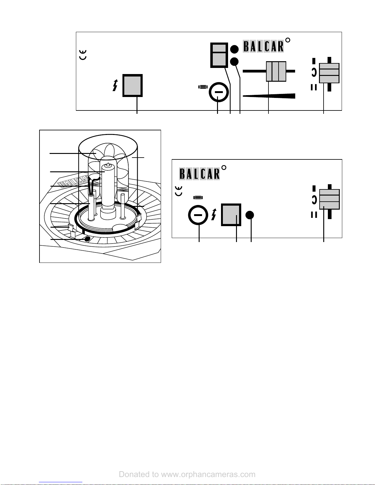
A1. Head flash trigger
A2. Fuse
A3. Full/half power switch
A4. Capacitor charge indicator
A5. Focus control
A6. Reflector holding system
control
B1. Flash tube
B2. Model lamp
B3. Trigger wire
B4. Glass tube
B5. Reflector holding clip (x3)
B6. Umbrella hole
B7. Pyrex holding ring
B8. Pyrex shell
FRANCAIS
A1. Déclenchement torche
A2. Fusible
A3. Sélecteur pleine/demi-
puissance
A4. Indicateur de charge
condensateurs
A5. Contrôle de la focalisation
A6. Réglage du système de
fixation des réflecteurs
B1. Tube flash
B2. Lampe guide
B3. Epingle d’impulsion
B4. Tube de verre
B5. Patte de fixation réflecteurs
(x3)
B6. Passage du parapluie
B7. Bague de fixation Pyrex
B8. Cloche Pyrex
DEUTSCH
A1. Manuelle Blitzauslösung
A2. Sicherung
A3. Leistungswahlschalter
1/2 oder 1
A4. Ladeanzeige Kondensatoren
A5. Fokussierschieber
A6. Arretierung
Reflektorhalterung
B1. Blitzröhre
B2. Einstellicht
B3. Zünddraht
B4. Zünddrahthalterung
B5. Reflektorhalterungen (3x)
B6. Schirmhalterung
B7. Pyrexhalterung
B8. Pyrexschutzglas
123 45 6
R
1234
Full
1/2
Made in France
Concept Z4
for use with P4 or Concept system
6.3A Fast
A
R
Made in France
Concept Z2
for use with P4 or Concept system
6.3A Fast
1 426
1
5
6
8
7
4
3
2
A
B
Donated to www.orphancameras.com

ENGLISH 3
The Concept Z head is designed for use with the following Balcar power packs : A/C P4 and Concept P4,
battery P2 and Concept B3. It is not compatible with the standard power pack systems (A, Star, Jet, Source
etc.)
The Concept Z head is delivered complete with flash tube(s), model lamp, Pyrex shell, FX60 facet reflector
and lamp protector.
The Concept Z head has built-in condensors, so total power is increased as more heads are connected.
The Concept Z2 and Concept Z4 operate in the same manner, except for the following : no focusing and no
full/half power switch on the Concept Z2.
1. Before connecting the head
Checking the flash tube (B1), model lamp (B2) and Pyrex (B8)
To ensure that the flash tube and model lamp are well inserted:
• slide the focus control to position 4 (Concept Z4 only).
• remove the Pyrex : give the shell quarter turn and pull the shell.
• check that the model lamp is properly screwed in, without touching the glass portion of the lamp. If
your fingers touch the glass of the model lamp, clean the model lamp using a cloth and alcohol.
To remove (or replace) the model lamp, you must first remove the flash tube.
Use the standard 150 W model lamp or up to 300 W maximum if the accessory and the flash unit can
handle it.
• if necessary, remove the flash tube by pulling on it (there are no screws to unfasten). Flash tubes are
polarized (+ and -) with different connector sizes. It is therefore impossible to insert a flash tube
backwards. Note that one of the connectors is loose to relieve pressure on the glass due to dimension
tolerances, heat dilatation and travel.
• make sure the trigger wire (B3) is properly inserted into the glass tube (B4), with its round section in
firm contact around the side of the flash tube. Squeeze the trigger wire prior to insertion if necessary.
• remount the Pyrex : insert one of the clip under the shell and push this clip towards the center in
order to insert the second clip under the shell. Turn the shell until the clips fit in the holes.
Checking the mounting system
Make sure the Pan/Tilt handle is tightly mounted onto the unit. Mount the unit on a stand of sufficient
weight and span to guarantee the stable operation of the unit.
Checking the connector
Make sure the head connector pins are not damaged. Also check the unit connector.
Any damage to the connector pins is not covered by warranty.
Donated to www.orphancameras.com
 Loading...