

Page 1
Installation Manual & Technical Data
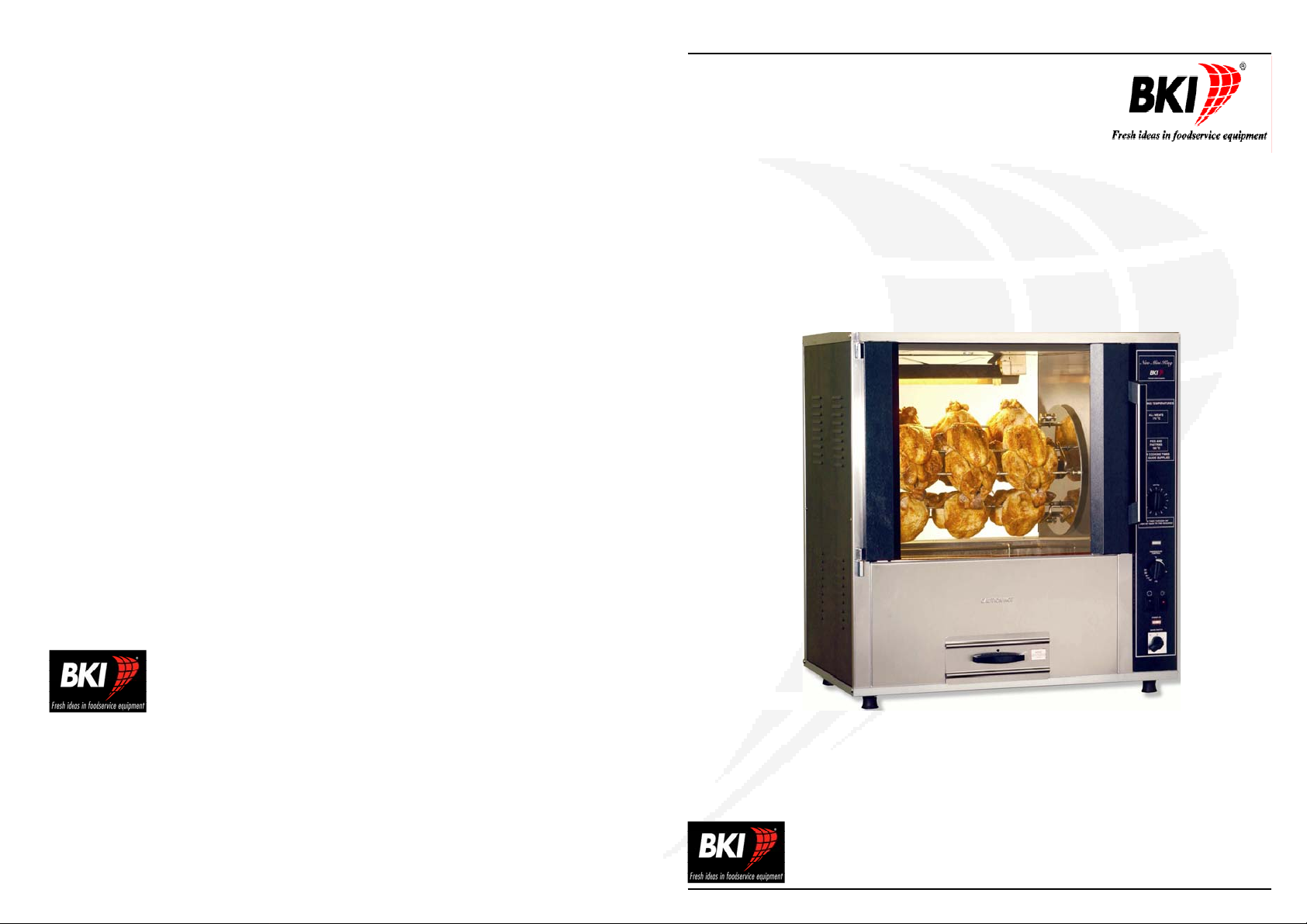
NMK Rotary Oven
BKI-Europe
Theale Technology Centre
Station Road
Theale
Reading
West Berks
RG7 4AA
Phone: 0870 990 4242 • Fax: 0870 990 4243 • www.bkideas.com
Printed in England CJM/NMKIM04006
16
Theale Technology Centre, Station Road, Theale, Reading, West Berks RG7 4AA
Phone: 0870 990 4242 • Fax: 0870 990 4243 • www.bkideas.com
ISSUE: APRIL 2006
Page 2
CONTENTS
SECTION PAGE
1. GENERAL………………………………………... 3
2. SITE REQUIREMENTS…………………………………. 4
3. CLEARANCES…………………………………………… 4-5
4. EXTRACTION……………………………………………. 6
5. ELECTRICAL CONNECTION………………………….. 7
6. SUPPLY CABLE - CONNECTION…………………… 8
7. OPERATING……………………………………………… 9
8. SAFETY CUT-OUT (RE-SET)………………………….. 10
9. GENERAL DIMENSION………………………………… 11
NOTES
10. WIRING DIAGRAM………………………………………. 12
BKI ROTARY OVENS ARE MANUFACTURED ACCORDING TO THE
FOLLOWING STANDARD:
BSEN 60 335-2-42: 2002
NOTICE : SAFETY CUT-OUT
For added safety all Rotary Ovens have a built in thermal cut-out to
protect against over-heating through component failure or incorrect
use.
If for any reason the thermal cut-out operates, the oven will automatically
shut down and should be switched `OFF` disconnected from the mains
and allowed to cool.
NOTE: THE THERMAL CUT-OUT WILL NOT RESET AUTOMATICALLY.
The oven must not be re-used until it has been checked by a
Qualified electrician or BKI Appointed Service Agent.
2
15
Page 3
NOTES
GENERAL NOTES & INFORMATION
Your `NMK` rotary display oven has been completely assembled and tested
before despatch.
It has been packed for safe shipment to you premises. Meatforks and other
accessories may have been packed separately, check all parts and accessories
against delivery note.
Before connecting to the power supply, ensure that all fittings and packaging
have been removed.
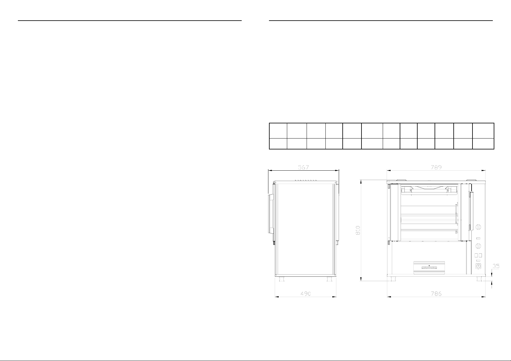
Table 1. TECHNICAL DATA
MODEL HEIGHT
mm
NMK 810 786 490 3 3 1ph 230 2.9 72 82
WIDTH
mm
DEPTH
mm
MEATFORKS
BASKETS PHASE VOLTS Kw WEIGHT
Amps
12.5
Nett
Kg
Gross
14
GENERAL DIMENSIONS
3
Page 4

SITE REQUIREMENTS
Refer to the appropriate general dimensions drawing for detail and dimen sion s o f
of model supplied (See Table 1. or General Dimensions - Page 12)
It is essential that this oven is installed in accordance with these instruction and
the installer is drawn to the following points:
• It is important that the counter top or base unit is level and can support the
full weight of the oven and its contents. Refer to Table 1 - Technical Data.
• For all types of installation it is important that adequate clearance is provided for ventilation and servicing of this appliance.
• It is recommended that this oven is sited on a stainless steel mobile base
for maximum service and cleaning access.
• Toughened glass doors are fitted to both sides of the oven for maximum
visual display and cleaning access. Door handles are fitted to the operators
side door only; customer side door handles are available as an optional
extra.
• It is important that adequate clearance is provided to enable doors to open
fully for safe loading and unloading of food items and oven removable
WIRING DIAGRAM
GND
GND
N L1
N
L1
9
9
10 GND
10GND
CLEARANCES
WARNING - HEALTH & SAFETY
Observe all safety warning labels affixed to this appliance.
We strongly recommended that careful consideration be given to the siting of this
piece of equipment in order to prevent accidental contact with hot surfaces.
The equipment is insulated but we cannot prevent certain surfaces such as glass
etc reaching temperatures, which can cause minor burns on contact .
PLEASE HELP PREVENT ACCIDENTS AND PROTECT THE SAFETY OF
YOUR STAFF AND CUSTOMERS
4
13
Page 5

GENERAL DIMENSIONS
CLEARANCES
• Restrictions must not be placed on or around this oven. Keep all ventilation
slots free from obstruction.
• Do not remove the rubber feet fitted to this oven.
• Refer to diagrams 1 & 2 for minimum recommended clearances required
from a combustible surface.
Minimum Distance from
Combustible Surface
A TOP 12”/305mm
B SIDE 2”/50mm
NOTE: DO NOT REMOVE RUBBER FEET
12
Minimum Distance from
Combustible Surface
D GLASS/DOOR 6”/152mm
WALL
D` GLASS DOOR/ 12”/305mm
WINDOW
(SHOP FRONT)
NOTE: DO NOT REMOVE RUBBER FEET
5
Page 6

EXTRACTION
Extraction is not a specific requirement for this type of appliance.
Certain conditions e.g.
Installation in a confined space, temperature controlled environment,
continuous use or high volume production cooking may require the need for
ventilation or extraction.
Consult your local Ventilation/Extraction, Air conditioning company or contact the
Technical Services Department at BKI.
ELECTRICAL CONNECTION
This appliance requires a 230V,50Hz single phase + Neutral + Earth power
Supply.
WARNING - THIS APPLIANCE MUST BE EARTHED
• Each appliance is despatched with an electrical test certificate.
• Check the details shown on the appliance data rating plate against the cer-
tificate supplied.
• Check that the voltage shown on the data plate and test certificate conforms with your power supply.
If the details do not conform contact the Technical Services Department at BKI
BKI Europe
Theale Technology Centre
Station Road
Theale
Reading
West Berkshire
RG7 4AA
Tel: (44) 0870 990 4242
Fax: (44) 0870 990 4243 Web: www.bkideas.com
Safety Cut-Out - Re-Set Button
If the safety thermal cut-out operates, first check that the oven has been installed
properly and is operated and cleaned in accordance with the installation and operating instructions.
• Turn the mains switch `OFF`, disconnect oven from mains power supply.
• Refer to the relevant wiring diagram and check all components and con-
trols before re-setting the safety thermal cut-out.
• The safety thermal cut-out is located within the oven control panel compartment. Reset the thermal cut-out as follows:-
1. Remove the two side panel securing screws, slide the panel `Up` and `Out`
at the bottom.
2. The safety thermal cut-out is sited towards the top left of the component
plate.
3. Press hard on the `Red` re-set button on top of the thermal cut-out (allow
time for the oven to cool down).
4. Replace side panel and check oven operation.
WARNING:
REPEATED OPERATION OF THE SAFETY THERMAL CUT-OUT IS A CLEAR
INDICTAION OF COMPONENT FAILURE OR MISUSE.
SERIOUS DAMAGE WILL OCCUR IF THE CAUSE IS NOT IDENTIFIED AND
RECTIFIED.
6
11
Page 7

OPERATING
Please read the operating instructions thoroughly and ensure all packaging ha s
been removed before switching mains power “ON”.
IMPORTANT:
Ensure that who-ever is operating this appliance is fully conversant with its working and is made aware of the dangers of incorrect operation.
If the operating manual is not available with the appliance, please contact the
Technical Services Department at BKI (See page 6)
Safety Cut-Out
For added safety `NMK` rotary ovens have a built in thermal cut-out to protect
against overheating through component failure or incorrect use.
If for any reason the thermal cut-out operates the oven will automatically shut
down and should be switched `OFF`, disconnected from the mains and allowed to
cool.
NOTE: THE THERMAL CUT- OUT WILL NOT RESET AUTOMATICALLY
The oven must not be re-used until it has been checked by a qualified electrician
or BKI appointed service agent.
ELECTRICAL CONNECTION
• Single phase appliances fitted with a power supply cable having a rated
input Not exceeding 3kW
means of a BS 1363 ASTA approved 13 amp plug fitted with a BS 1362
fuse.
• Do not use an adaptor or extension lead, plug directly into a 13 amp socket
outlet.
• Check the appliance data rating plate and test certificate for appliance fuse
rating.
• Where a 13 amp plug is required, please follow the instructions below:
WARNING - THIS APPLIANCE MUST BE EARTHED
IMPORTANT:
The wires in the mains lead are coloured in accordance with the following code:
GREEN & YELLOW EARTH
BLUE NEUTRAL
BROWN LIVE
As the conductors in the equipment mains lead may not correspond with the
coloured markings of the terminals in your plug, proceed as follows:
The wire that is coloured green & yellow must be connected to the terminal in the
plug that is marked with the letter E or by the Earth symbol or coloured
green or green & yellow.
The wire that is coloured blue must be connected to the terminal that is marked
with the letter N or coloured black.
The wire that is coloured brown must be connected to the terminal that is marked
with the letter L or coloured red.
may be connected to a suitable power supply by
10
7
Page 8

ELECTRICAL CONNECTION
• IMPORTANT: If this appliance is not connected to an electrical supply by
means of a BS 1363 13 amp plug it must be connected to a suitable electrical supply by a qualified electrician in accordance with the latest edition of
the I.E.E WIRING REGULATIONS.
• NOTE: A method of disconnection from the mains supply having a contact
separation of at least 3mm in all poles must be incorporated in the fixed
wiring.
• It is recommended that an R.C.D device with a 30ma trip and contact rating
to suit the appliance current is installed adjacent to the appliance.
• Type 3 circuit breakers or appropriate rated fuses are recommended for
installation at the supply end.
• NOTE: High surge currents are present when this appliance is switched
on from cold.
• Industrial plugs and sockets must comply with BS 4343/EN60.309
(IEC309.2/CEE17).
• It is recommended that the supply cable shall be an oil resistance sheathed
flexible cable to BS 6500 1990 table 6 (code designation HO5 RN-F).
• If the appliance power supply cord is damaged or changed it must be replaced to the above standard and must not be longer than 2 metres between appliance inlet and plug or socket outlet.
• It is required that, in the power supply cable connection to the appliance
terminal block; the earth conductor is to be made at least 50mm longer than
the length of the live (L) and neutral (N) conductors, so that if the cable is
strained the earth conductor is the last to become disconnected.
• For appliances with a rated current upto and including 16amps, 1.5mm
cable should be used.
2
SUPPLY CABLE - CONNECTION
• To gain access to the control panel and terminal connection block, remove
the two side panel securing screws, slide the panel “up” and “out” at the
bottom.
• The terminal connection block is sited toward the the bottom left hand side
of the control box. Cable entry is provided through the base of the oven.
• Refer to terminal connection block diagram for correct connection.
NMK MAINS BLOCK
Supply rail connections - 230V, Single Phase
WARNING - THIS APPLIANCE MUST BE EARTHED
GND
GND
10
9
L1
N
GND
10
N L1E
9
Live
Neutral
Earth
8
9
 Loading...