

Page 1
BAKERS
PRIDE
INSTALLATION AND OPERATING INSTRUCTIONS
IL FORNO CLASSICO OVENS
Series: FC-516, FC-616 and FC-816
INTENDED FOR OTHER THAN HOUSEHOLD USE
OVEN MUST BE KEPT CLEAR OF COMBUSTIBLES AT ALL TIMES
RETAIN THIS MANUAL FOR FUTURE REFERENCE
IMPORTANT INSTRUCTIONS
Afterthegassupplyhasbeenconnectedtoyourunit,it is extremely importanttocheckpipingfor
possible leaks. Todo this,use soap and watersolutions,or solutions which areexpresslymade for this
purpose. DO NOT USE matches, candles, flames, or other sources of ignitions since these methods
areextremelydangerous.
In a prominent locationpost instructionsto befollowedin the event you smellgas. Obtain these
instructionsfromyourlocalgassupplier.
FOR YOUR SAFETY
Do not store or usegasoline orother flammablevapors
andliquidsin the vicinity of this or any other appliance.
WARNING
Improper installation, adjustment, alteration, service or maintenance can cause property damage,
injury or death. Read the Installation, Operating and Maintenance Instructions thoroughly before
installingor servicing this equipment. Initial heating of ovenmay generate smokeor fumes andmust be
donein a well ventilated area. Overexposuretosmokeorfumesmaycausenauseaordizziness.
NOTE:
productsmustbeplacedinpansor containers to avoid direct contact with Ceramic Decks.
This equipment has been engineered to provide you with year round dependable service when used
accordingtotheinstructionsinthismanualandstandardcommercialkitchen practices.
Only Pizza and Bread Products can have direct contact with Ceramic Decks. All other food
I
G
S
N
E
D
C
E
D
R
E
I
T
I
F
R
CERTIFIED
R
4/03 Form #U4116A
BAKERS PRIDE OVEN CO., INC.
30 Pine Street
New Rochelle, NY 10801
(914)576-0200 Phone (800)431-2745 US& Canada
(914)576-0605 Fax www.bakerspride.com WebAddress
1
Page 2

2
Page 3
INDEX
I. INSTALLATION INSTRUCTIONS
1. Receiving 3
2. Clearances 3
3. Set-up 3
A. Mounting Legs with Casters 3
4. Pizza Decks & Optional Ceramic Top
A. Three Deck Installation 4
B. Four Deck Installation 4
C. Optional Ceramic Top Installation 4
5. Booster Burner Installation 4
6. Gas and Electric Connections 4
7. Main Burner Safety Pilot Operations 5
A. Pilot Burner Lighting Procedure 5
B. Pilot Burner Flame Adjustment 5
8. Burner Operation 5
A. Main Burner 5
B. Booster Burner 5
C. Aeration & By-Pass Flame
Adjustment. 5
9. Thermostat Calibration 6
10. Flame Diverters 6
II. OPERATING INSTRUCTIONS
III.CLEANING and MAINTENANCE
1. Stainless Steel Surfaces 7
2. Painted Surfaces 7
3. Door Mechanism 7
4. Flue Vent 7
5. Oven Interior 7
A. Baking Chamber 7
B. Bake Decks 7
C. Burner Compartment 8
6. Parts Breakdown 8
7. Sales & Service Centers 9
Installation Figures/Illustrations 10 &11
Wiring Diagrams 12
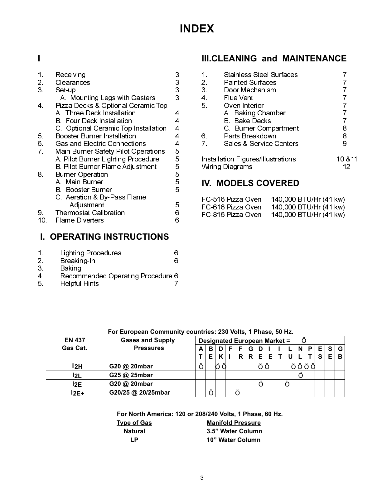
IV. MODELS COVERED
FC-516 Pizza Oven 140,000 BTU/Hr (41 kw)
FC-616 Pizza Oven 140,000 BTU/Hr (41 kw)
FC-816 Pizza Oven 140,000 BTU/Hr (41 kw)
1. Lighting Procedures 6
2. Breaking-In 6
3. Baking
4. Recommended Operating Procedure 6
5. Helpful Hints 7
For European Community countries: 230 Volts, 1 Phase, 50 Hz.
EN 437
Gas Cat.
I
2H
I
2L
I
2E
I
2E+
Gases and Supply
Pressures
G20 @ 20mbar
G25 @ 25mbar
G20 @ 20mbar
G20/25 @ 20/25mbar
For North America: 120 or 208/240 Volts, 1 Phase, 60 Hz.
Type of Gas
Natural 3.5” Water Column
LP 10” Water Column
Designated European Market = Ö
ATBEDKFIFRGRDEIEITLUNLPTESSEG
B
Ö ÖÖ ÖÖ ÖÖÖÖ
Ö
ÖÖ
ÖÖ
Manifold Pressure
3
Page 4
I. INSTALLATION INSTRUCTIONS
1. RECEIVING:
Read the notice on the outside carton regarding damage in transit. Damage discovered after
opening the crate(s)/ carton(s) is CONCEALED DAMAGE andthe carrier mustbe notified immediately to
sendan inspectorandalsofurnishtheformsfor the consignee'sclaimagainstthecarrier.
When oven arrives, it should consist of : A crate, or carton, containing your new oven, a carton,
containing4legswithmountinghardware,and astrapped skid, containing baking decks.
Installation must conform withlocal codes and/orwith the latestedition of the ANS Z-233.1National
FuelGas Code in USA/ CAN/CGA-B 149.1 or 2 Installation Code in Canada.
This appliancemust be installed by a competent person. In the U.K., Corgi registered Installers (including
the regions of British Gas) undertake to work to safe and satisfactory standards. This appliance must be
installed in accordance with the current Gas Safety (Installation and Use) Regulations and the relevant
Building Regulations / IEE Regulations. Detailed recommendations are contained in the British Standard
CodesOfPracticeBS6172,BS5440:Part2and BS 6891.
Placetheovenand partsascloseaspossibletotheareaoffinalinstallationbefore un-crating.
2. CLEARANCES:
MinimumClearanceFrom CombustibleConstruction Non-Combustible Construction
LeftSide 3 (76 mm) 0
RightSide 1 (25 mm) 0
Rear 3 (76 mm) 2 (51 mm)
FrontandFlueArea - Enclose only with non-combustible materials.
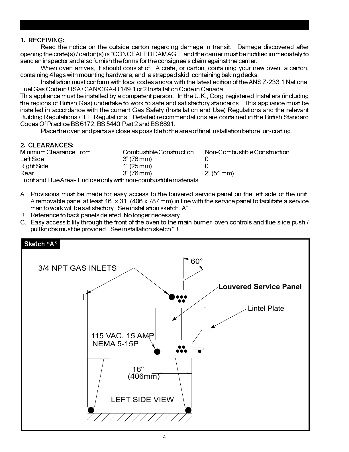
A. Provisions must be made for easy access to the louvered service panel on the left side of the unit.
A removable panel at least 16 x 31 (406 x 787 mm) in line with the service panel to facilitate a service
manto work will be satisfactory. Seeinstallation sketch A.
B. Referenceto backpanels deleted. No longer necessary.
C. Easy accessibility through the front of the oven to the main burner, oven controls and flue slide push /
pullknobsmustbe provided. See installationsketchB.
Sketch A
60°
3/4 NPT GAS INLETS
Louvered Service Panel
Lintel Plate
115 VAC, 15 AMP
NEMA 5-15P
16"
(406mm)
LEFT SIDE VIEW
4
Page 5
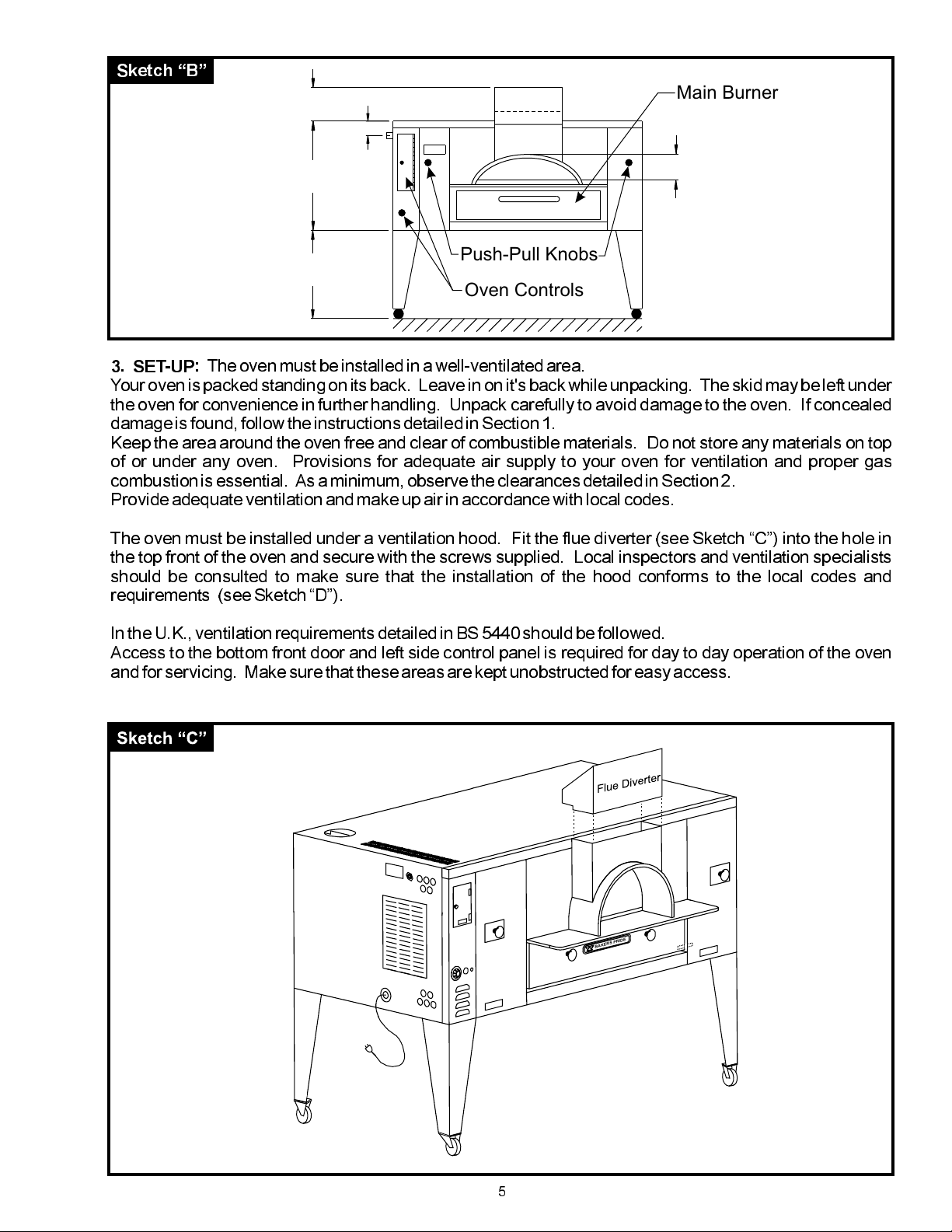
Sketch B
12"
(305mm)
FRONT VIEW
Main Burner
33"
(838mm)
30" STD.
(762mm)
21/4
(57mm)
Push-Pull Knobs
10”
(254mm)
Oven Controls
3. SET-UP:
Your oven is packed standing on its back. Leave in on it's back while unpacking. The skid may be left under
the oven forconvenience in furtherhandling. Unpack carefully to avoid damageto the oven. If concealed
damageisfound,followtheinstructionsdetailedin Section1.
Keep the area around the oven free and clear of combustible materials. Do not store any materials on top
of or under any oven. Provisions for adequate air supply to your oven for ventilation and proper gas
combustionisessential. As a minimum, observe the clearances detailedinSection2.
Provideadequateventilationandmakeupairinaccordancewithlocalcodes.
The oven must be installed under a ventilation hood. Fit the flue diverter (see Sketch C) into the hole in
the top front of the oven and secure with the screws supplied. Local inspectors and ventilation specialists
should be consulted to make sure that the installation of the hood conforms to the local codes and
requirements (see Sketch D).
Theovenmustbe installedinawell-ventilatedarea.
In the U.K., ventilationrequirementsdetailed in BS 5440 should be followed.
Access to the bottom front door and left side control panel is required for day to day operation of the oven
andfor servicing. Make sure that these areas are kept unobstructedfor easy access.
E
D
I
R
P
S
R
E
K
A
B
5
Page 6

Sketch DSketch D
Vent Hood (Not Included)
BAKERS PRIDE
A. MOUNTINGLEGSWITHCASTERS:
Legs are shipped in a separate carton complete with mounting hardware and casters, (two of them with
wheelbrakes).
NOTE : Installation shouldbe madewith a connector that complies with the latest edition of the Standard
for Connectors for Movable Gas Appliances ANSI Z21.69 in the USA (CAN CGA6.16 in Canada) and a
quick disconnect device that complies with the latest edition of the Standard for Quick Disconnect Devices
for use with gas fuel ANSI Z21.41 in the USA (CAN CGA 1-6.9 in Canada) and adequate means must be
provided to limit the movement of the appliance without depending on the connector and any quick
disconnect device or itsassociated piping. Therestraint should be attachedto the rearlegs of theoven on
which casters are mounted. If disconnection of the restraint is necessary to move the oven for servicing
needs, the restraint should be reconnected after the appliance has been returned to its originally installed
position.
a) Bolt two(2) legswith castersandwheel brakes firmly to thetwo (2)upper (front)corners oftheoven as it
standsontheskid (seeSketchE).
b) Using proper lifting equipment, lower the oven down so that the two bolted legs rest on the floor (see
SketchF).
c) Using proper lifting equipment,raise the back side of the oven toa height slightly higher than the height
of the legs, remove the skid and place a sturdy support under the back side (see Sketch G). Mount
remainingtwo(2)legsandtightenbolts. Lifttheovenandremovethesupports.
d) Move the oven to its final location, keeping the minimum clearances from the back of the oven to the
wall. Thisclearanceisnecessaryforsafeoperationandtoprovideproperairflowtotheburnerchamber.
6
Page 7

Sketch E
Sketch F
E
D
I
R
P
S
R
E
K
A
B
E
ID
PR
S
R
E
K
A
B
Sketch G
7
Page 8

Sketch I
Wedges
Four Deck
C. Optional CeramicTop Installation:
If the ovenwas ordered withthe ceramic topoption, the twotop supports are alreadyinstalled. Simply slide
in the ceramic tops as per instructions below. If this option is an add-on, you must follow the instructions
providedwiththeCeramicTop Installation kit.
a) Through the arched front opening, insert one of the center slabs (20 13/16 x 20 13/16 for FC616 and
FC816)(17 1/2 x 17 3/4(left to right)for theFC516)into the bake chamber,raise one side until the otherside
comes to restonto the centersupport, then lowerthe first sideto lock it in between the two center supports.
Pushit to the rear as far as possible to make room for the second center slab.
b) Install the second center slab (20 13/16 x 20 13/16 for FC816)(14 3/16 x 20 13/16 (left to right) for
FC616)(17 1/2 x 17 3/4 (left to right) for FC516) into the bake chamber and push it tightly against the first
slab.
c) Install the side slabs (2013/16 x 20 13/16for FC816)(17 1/2 x17 3/4 (left to right)for FC616)(17 1/2 x13
3/4 (left to right) for FC516) in a similar fashion, raisingthe slab in the center until the lower side edge rests
on the side support, then lowering the upper edge onto the center support. First the ones in therear,thenthe
onesin the front, pushing them tightly againstthe first slabs.
5. BOOSTERBURNERINSTALLATION:
NOTE: The Booster Burner and the Booster Burner Guard are shipped inside the burner
compartmentand have to be installed before the booster burner can be used for the first time.
a) Once the Pizza DeckSlabs are installed as per instructions above, place the booster burner and guard
insidethebakechamber, asfar back as possible, then follow with your upper torso and do the following:
b) Center the guardin frontofthe booster burner brackets, flange down,wings back,then pushitall the way
backandunderthe boosterburnerbrackets.
c) Reach over the guard, slip thethroat of thebooster burner over thegas nozzle, thenlower it andinsert the
twoburnerendsintothe locatingslotsoftheboosterburnerbracketsand pushthem all the way down.
6. GASAND ELECTRICCONNECTIONS:
NOTE:PropaneGas Units are not available in the European Community.
A) Normalfactory connections are made for 120Volts AC, 60Hz operation inUSAand Canada. For use in
Europe,theconnectionsaremadefor230VoltsAC,50 Hz operation.
b) The appliance, when installed, must be electrically groundedin accordance with local codes and/or the
latest edition of the National Electric Code /NFPA 70 in USA (Canadian Electric Code CSA C22.2 in
Canada).
c) In Europe, the appliance must be connected by an earthing cable to all other units in the complete
installation and thence to an independent earth connection in compliance with EN 60335-1 and/or local
codes.
ANSL
8
Page 9

d) The hot surface ignition system, all related switches, indicator light and fuse, are all connected through
the 6 ft (1830 mm) power supply cord. The power supply cord must be plugged into a properly grounded
three-prongreceptacle.
Donot cut or remove the ground prong from the plug.
e) A wiring diagram may be found behind the service panel on the left side of the unit and also in this
manual.
f) The ovens should not be installed on the same line with space heaters, boilers or other gas equipment
withhighintermittentdemand.
g) Use a pipe joint compound that is resistant to the action of liquefied petroleum gases when making gas
connections.
h) For Propanegas,usea least ½ pipe or tubing with a 5/8 inside diameter. For Natural gas, use ¾ pipe.
i) The appliance must be isolated from the gas supply piping system by closing its manual shut-off valve
during any pressure testing of the gas supply piping system at test pressures equal to or less than ½ psig
(3.45kpa).
j) Theappliance and its shut-off valve must be disconnectedfrom the gassupply piping system duringany
pressuretestingofthatsystemattest pressuresinexcessof ½ psig(3.45kpa).
k) The gas pressure regulators are part of the combination valves and are adjusted to yield a pressure of
3.5 water column (9 mbar) for Natural Gas. If the oven has been ordered for use on Propane Gas, the
pressure regulators in the combination valves are preset at the factor to yield a pressure of 10 water
column(25mbar).
l) A separate shut-off valvefor each ovenmust be provided. It shouldbe as closeas possible tothe place
wherethegas line enters the oven. It must be located where it is easily and quickly accessible.
m) When stacking with another typeof oven,two (2)shut-off valves, one foreach ofthe twoovens, mustbe
provided.
After the gas supply has been connected, it is extremely important to check all the piping for leaks. Use a
soap and water solution or a product made expressly for this purpose. Do not use matches, candles or a
flameetc.to check leaks since these methodsareextremelydangerous.
7. SAFETYPILOTOPERATION:
The purpose of the safetypilot system is to lock the gas supply to the burner at the combination valve, if for
any reason the pilot burner is not lit. The pilot should be re-lighted by following the steps given below.
However, in normal service, the pilot flame stays lit indefinitely, day and night, including weekends. This
prolongsthelifeof the safety valve.
The safety pilot valve is in effect a two-stage control. After initial lighting, the pilot burner stays on without
the gas cock dial being held pressed in. After 1-2 minutes, the valve opens fully to let the gas flow past the
safetypilotvalveandinto the burner system.
A. PILOT BURNERLIGHTINGPROCEDURE:
A) Partially depressand turn the gas cock dial to the OFF position.
b) Waitforfiveminutestoallowgas,whichmayhaveaccumulatedin theburner compartment, to escape.
c) Turngas cock dial to PILOT position.
d) Depress gas cock dial.
For Main Burner:
e) With a match or igniter light pilot burner. Hold gas cock dial in pressed position for
about 1/2 minute and then release it. The Pilot Burner flame should now remain lit.If Pilot Burner fails to
igniteor does not remain lit, repeat steps(a)thrue).
For Booster Burner:
f) Flip toggle switch to the ON(I) position. The amber indicator lamp willlight up and
the igniter will be energized and start to glow. Hold gas cock dial in pressed position for about 2-3 minutes
and then release it. The Pilot Burner flame should now remain lit. If Pilot Burner fails to ignite or does not
remainlit,repeatsteps(a)thru(d)and(f).
Note:
The built-in igniter is for convenience of lighting only and not necessary for the booster burner
operation. In case of power failure, or if the igniter will not light the pilot flame,the pilot flame can also be lit
witha long hand-heldigniteror with a long, lit taper.
B. PILOT BURNERFLAMEADJUSTMENT:
It is important to have the correct Pilot Burner Flame size as shown in (Sketch J). If necessary, adjustthe
Pilot Burner Flame by turning the PilotAdjustment Screw (see Sketch K) clockwise to reduce or counter-
clockwisetoincrease.
9
Page 10

Sketch J
Sketch K
Pilot
Feed
Correct Flame
3/8” - 1/2”
Pilot
Adjust
Screw
IN
FF
PILOT
P
I
L
OFF
O
T
ON
Gas
Cock
TH
TP
TP
TH
VENT
Dial
Pressure
Regulator
650
600
550
500
450
300
350
400
Thermostat
8. BURNER OPERATION:
A. MAIN BURNER:
After the pilot burner is ignited, when heat is desired, turn gas cock dial to the ON position and set the
thermostatdial to the desiredtemperature. Theoven burnerflameshould always have a blueappearance.
That indicates a good mixture of gas and air. When using LP gas, the flame will have a blue-yellow
appearance.
B. BOOSTERBURNER:
Do not turn on the booster burneruntil the oven is well pre-heated and the pre-set temperature has
beenreached.Theovenhastobe hot in order to draw fresh air in to the booster burner.
After the pilot burner is ignited, when the booster burner flame is desired, turn gas cock dial to the ON
position.Theboosterburner is setto have a yellow flickering flame, but should not soot.
Should the Burners fail to light, check to see if there is a problem with the gas supply. If there are other
appliances on the same line, shut them off temporarily and see if the burners come back on, or they
fluctuate as other gas appliances are turned on and off. That would indicatean overload of the gas supply
lines or a faulty gas pressure regulator. Contact an authorized Service Agency or your local Gas Supply
Company.
10
Page 11

C. AERATIONand BY-PASS FLAMEADJUSTMENT:
Flame and air mixer adjustments for the Main Burner and the Booster Burner, and the By-Pass Flame
adjustment for the Main Burner are all done at the factory. These adjustments are sealed before the oven
leavesthefactory. Contact an authorized ServiceAgency if youneed help.
9. THERMOSTATCALIBRATION:
No attempt should be made tocalibrate thethermostat because it isaccurately calibratedand sealed bythe
manufacturer. Contact an authorized ServiceAgency if youneed help.
10. FLAME DIVERTERS:
Flame diverters distribute the heat evenly below the baking deck. They must be in good condition and
properly placed above the burners in the burner chamber in order to be effective. Damaged or improperly
installed flame diverters adversely affect the oven performance. Make sure that the "V-shaped diverters
are pushed all the way to the back of the oven as far as they will go. Check them periodically and replace
themas necessary.
If gas odor is detectedat anytime, immediately shut off thegas supplyvalve to theoven. Donot permitany
open flames in the area of the oven.
Immediately contact an authorized Service Agency or your local
GasSupplyCompany.
Initial heating of theoven must be donein a well-ventilatedarea asit may generate smokeor fumes. Over-
exposuretosmokeorfumesmaycausenauseaordizziness.
1. LIGHTINGPROCEDURE:
a) Light the Main Burner following the instructionsin Section7Aof the Installation Instructions.
b) Keep the Push/Pull Slides fully open.
2. BREAKINGIN:
A break-in period, after installing a new oven, is important to allow the deck and the insulation to dry out.
Bakinginthe oven before a break-in period will result in poor performance. For breaking in:
a) Allow the oven to warm to 300 F (150 C) for 5 hours or at least until all the smoke and fumes have
disappeared. The smoke and fumes are from the moisture in the deck andinsulation and a light coat of oil
onall of the sheet metal.
b) Set the thermostatatleast50 F (30 C) lower than your baking temperature.
c) Pre-heat the oven for 1 to 1 ½ hours before use.
d) After this pre-heating, raise the temperatureto your baking temperature.
e) Light the Booster Burner followingthe instructionsinSection7Bof the InstallationInstructions.
f) Experimentbakinguntilyou get the feel of the oven and the speed of the bake.
3. BAKING:
Pizza can bebaked on the deck, on a screen or in a pan. When you determinethe combination ofmethod,
ingredients and temperature that gives the right bake for your crust, sauce and cheese combination and
yourcustomer'staste,markitdownandkeepit. Consistencyisthekeyto repeat business
.
Deck baking refers to placing the pizza directly on the deck to bake. Generally, it is a thin product that
requiresahighbakingtemperatureofatleast550 F (290 C).
Screenbakingreferstoplacingthepizzaon a screen to bake. The screen keepsthepizzaoffthedeck. The
11
Page 12

4. RECOMMENDEDOPERATING PROCEDURE
It is very important that at the end of each day's operation, the gas cock dial to the Main Burners is turned
back to the Pilot positionand thatthe BoosterBurner switchis flippedto theOFF(O) position, leaving only
thePilot Burneron overnight.KeepthePizzaPush/Pullslidesfullyopen.
Pre-heating:
a) Turnthe gas cock dial to the mainburner to the ON position.
b) Pre-heat the oven for 1 to1 ½ hours at 50 F (30 C) lowerthan your bakingtemperature with Push/Pull
oo
slidesfullyopen.
Baking:
a) After pre-heating, raise the thermostatsettingtoyourbakingtemperature.
b) Light the Booster Burner and startbaking.
c) Check the bottom color of the Pie and close the Push/Pull slides partially (halfway) after the 4th or 5th
baketo maintainthedesiredcolor.
When slow oridling, open thePush/Pull slides fullyand set thethermostat at least 50 F (30 C) lower
oo
than your baking temperature in orderto preventthe bakedeck fromgetting too hot.
5. HELPFULHINTS:
a) An instructions plateis attached behind thedamper knobs indicating howto set theoven for more top or
more bottom heat. Openingthe slidesallowsmore heat to enterthe bakingchamberfrom the combustion /
burner compartment. Closing the slides keeps moreheatin the combustion / burner compartment, thereby
makingthebakedeckhotter.
b) Ifthe oven is upto bake temperature buthas not been usedfor a while, thereis a tendencyfor the decks
to get very hot. In this condition,when you put in onepizza, so that the main
TURNTHE THERMOSTATUP
burner flame is at its fullest, providing the extra heat needed to balance the high bottom heat. The
thermostatshouldbe turneddown back to the normal setting, as soon as that pizza is baked.
c) Frequently scrape and brush off decks to remove burntresidue which can cause an off-flavourand an
increaseinthebaketime.
d) Heavily topped pizza or pan pizza requires lower bake temperatures and longer bake times as
comparedtoregularthinpizzawithlighttoppings.
e) Bubbles in fresh dough indicate an under-proofed or cold product. Allow the dough balls to proof to
doubleinsize and warm to room temperaturebeforebaking.
f) Any type of pan or screenmay be used inthis oven. When choosingpans,be sure topick a pan whichis
closestinheightto that of your product.
Dark color Pans andScreens transfer heat betterthan light colored aluminumPans orScreens. All
PansandScreensmustbeseasonedbeforeuse.
III. CLEANING and MAINTENANCE
THISAPPLIANCE MUST BE SERVICED ONLY BYAN AUTHORIZED SERVICEAGENT
Bakers Pride ovens are designed to be as maintenance-free as possible. Regular and thorough cleaning
will help to keep the ovens operating properly. However, if service is required, contact an Authorized
ServiceAgency or your Dealer.
Disconnectthepowersupplybeforecleaningorservicingthe oven.
1. STAINLESS STEEL SURFACES:
a) Deposits of baked-on splatter and grease, or discoloration, may be removed with the stainless cleaner
sample supplied orby using anycommercial cleaner recommended forstainlesssteel. Bakers Prideoffers
a stainlesssteelcleanerexpresslymadeforthispurpose.RINSEWELL.
b) Apply a thin coat of oil to protect and enhance the finish.
NOTE: Apply stainless steel cleaner only when the oven is cold. Always rub with the grains while
applyinglightpressure.
12
Page 13

2. PAINTEDSURFACES:
a) Washingwith mild soap and watersolution is usually adequate to keep the outside clean.
b) Apply a thin coat of oil to protect and enhance the finish.
3. DOOR MECHANISM:
Every six months (more frequently if the oven is used heavily) the bottom door spring mechanism and all
movingpartsmust be inspected for wear.
Do not apply grease to spring lever shoulder bolt, spring roller or the door rod and the door pin.
Theyhaveself-lubricatinginsertsthat will be damaged when lubricated.
4. FLUE VENT:
TheVentilationSystem must be inspected every six months and maintainedcleanandfreeof obstructions.
5. OVEN INTERIOR:
Clean the oven interioronly whenthe ovenis cold. Use onlythe detergent solutions and cleaners thatmeet
thenationaland/orlocalcodes.
A. BAKING CHAMBER
Cleanthe ceiling and the walls of the baking chamber with amild soap and watersolution.
:
Do not use oven
cleaners, caustic solutions or mechanical means as this will damage the interior aluminized
surfaces. Use caution when cleaning around the booster burner so as not to damage the ceramic
igniter.
B. BAKE DECKS:
Thebakedecksare heavyand fragile and they should be handled carefully.
The bake decks should be cleaned by using a long-handled scraper and a stiff wire brush. At the end of
each day, turn the thermostat uptoits maximum setting and let theovensit at that temperaturefor atleast ½
hour. This will burn off the food spilled onto the bake decks during the day's production and turn it into ash.
This ash can be brushed off the next morning before turning the oven on. The bake decks should also be
scraped and brushed during theday to help keep them clean. To remove excessive crumbsor carbon, the
bake decks andthe oven cavity may be vacuumed whenthe oven iscold. Do not usewater or otherliquids
on the bake decks as this may cause them to crack. After long use, heavily soiled bake decks may be
cleaned by turning them over, after they have been scrapeddown and brushedoff. This willeventually burn
offtheheavilysoiledsideofthebakingdecks. This procedure may be repeated as needed.
C. BURNER COMPARTMENT:
Vacuum out any carbon or residue in the burner compartment and all around the bottom door. The holes
and louvers on the outer surfacesof theoven mustbe keptfree ofobstructions to allowfreemovementof air
forpropercombustionandcoolingofthecontrols.
13
Page 14

14
Page 15

15
Page 16

BAKERS
PRIDE
BAKERS PRIDE OVEN CO., INC.
30 Pine Street
New Rochelle, NY 10801
(914) 576-0200 Phone (800) 431-2745 US & Canada
(914) 576-0605 Fax www.bakerspride.com Web Address
16
16
 Loading...