

Bakers Pride V800 Service Manual
1
IMPORTANT INSTRUCTIONS: After the gas supply has been connected to your
unit, it is extremely important to check piping for possible leaks. To do this, use soap
and water solution or solutions that are expressly made for this purpose.
DO NOT USE matches, candles, flames, or other sources of ignition since these
methods are extremely dangerous. Post in a prominent location instructions to be
followed in the event you smell gas. Obtain these instructions from your local gas
supplier.
FOR YOUR SAFETY: Do not store or use gasoline or other flammable vapors or
liquids in the vicinity of this or any other appliance.
WARNING: Improper installation, adjustment, alteration, service or maintenance can
cause property damage, injury or death. Read the Installation, Operating and
Maintenance Instructions thoroughly before installing or servicing this equipment.
Initial heating of oven may generate smoke or fumes and must be done in a well
ventilated area. Overexposure to smoke or fumes may cause nausea or dizziness.
INSTALLATION AND OPERATING INSTRUCTIONS
FLOOR MODEL GAS DECK OVENS
Series: Vantage 600 and 800
INTENDED FOR OTHER THAN HOUSEHOLD USE
RETAIN THIS MANUAL FOR FUTURE REFERENCE
OVEN MUST BE KEPT CLEAR OF COMBUSTIBLES AT ALL TIMES
Note: Only Pizza or Bread can have direct contact with Fiberment decks. All other food products must be
placed in a pan or container to avoid direct contact with Fiberment decks.
This equipment has been engineered to provide you with year round dependable service when used
according to the instructions in this manual and standard commercial kitchen practices.
BAKERS PRIDE OVEN CO. INC.,
1307 N. Watters, Ste. 180
Allen, Texas 75013
+1 (800) 431-2745 US & Canada
www.bakerspride.com Web Address
P/N U4281A 8/13
2
CONTENTS
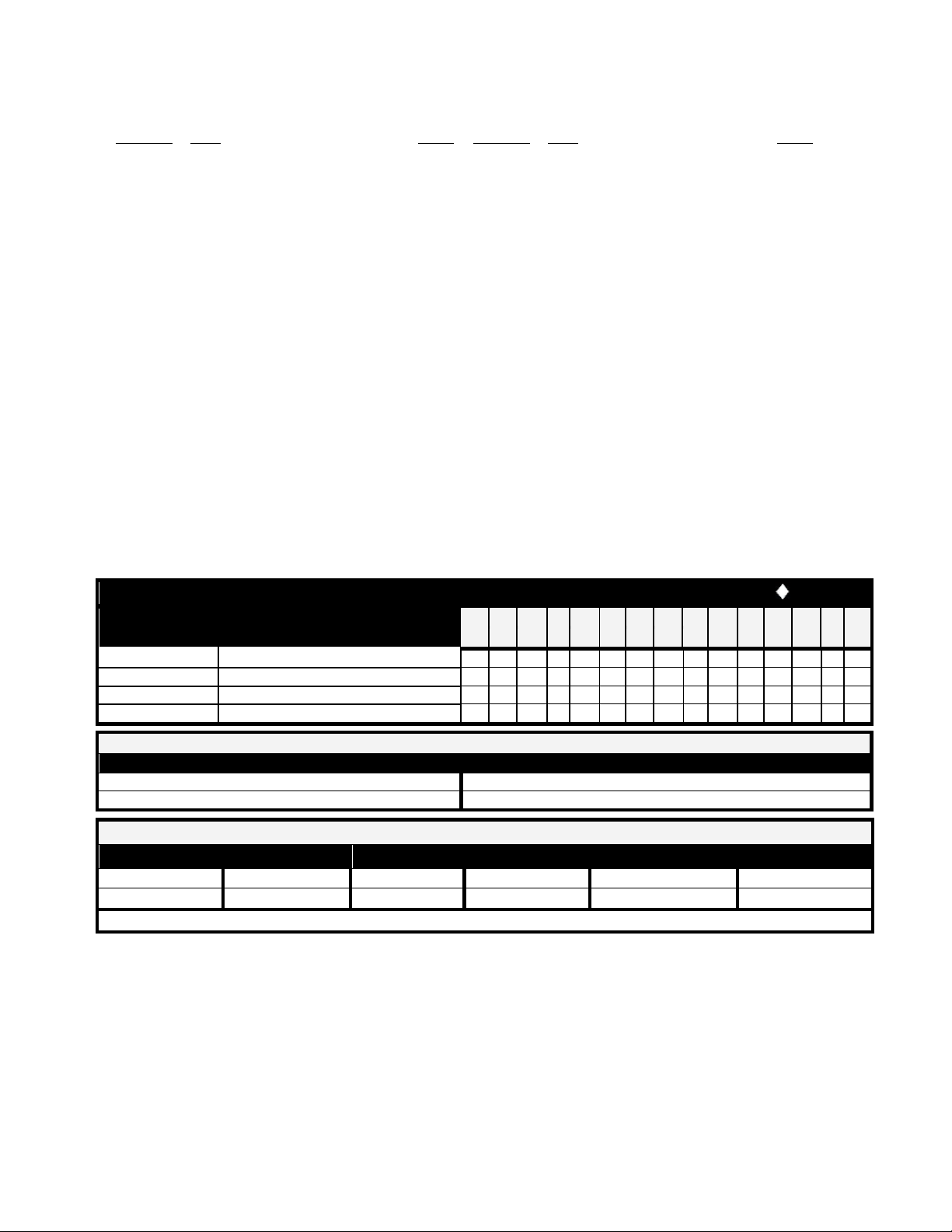
EN 437
Gas and Supply
Designated European Market =
Gas Cat.
Pressures
A B D F F G D I I L N P E S G T E K I R R E E T U L T S E
B
I2H
G20 @ 20mbar
I2L
G25 @ 25mbar
I2E
G20 @ 20mbar
I
2E+
G20/25 @ 20/25mbar
FOR NORTH AMERICA:
TYPE OF GAS
MANIFOLD PRESSURE
Natural
3.5" Water Column
LP
10" Water Column
MODELS COVERD:
MODEL
BTU/HR
KW
MODEL
BTU/HR
KW
V-600
120, 000
35.15
V-800
120, 000
35.15
LP Gas models are not available for European Community Countries.
I. INSTALLATION INSTRUCTIONS
SECTION ITEM PAGE
1 Receiving .................................................... 3
2 Clearances.................................................. 3
3 Set-up ......................................................... 3
(a) Mounting Legs .................................... 4
(b) Installation with Casters ...................... 4
4 Pizza Decks ................................................ 4
(a) Deck Installation ................................. 4
5 Gas Connections ........................................ 5
6 Flue connection-Ventilation ........................ 6
(a) Under Ventilation Hood....................... 6
(b) Direct Venting ..................................... 6
7 Main Burner Safety Pilot Operation ............ 6
(a) Pilot Burner Lighting Procedure .......... 7
(b) Pilot Burner Flame Adjustments ......... 7
8 Burner Operation ........................................ 7
(a) Main Burner ........................................ 7
(b) Aeration & By-Pass Flame Adjustment ..... 7
II. OPERATING INSTRUCTIONS
SECTION ITEM PAGE
1 Lighting Procedure ....................................... 8
2 Breaking In ................................................... 8
3 Baking .......................................................... 8
4 Recommended Operating Procedure .......... 8
5 Helpful Hints................................................. 8
III. CLEANING AND MAINTENANCE
1 Oven Exterior ............................................... 9
2 Control Panel ............................................... 9
3 Flue Vent ..................................................... 9
4 Oven Interior ................................................ 9
(a) Baking Chamber .................................. 9
(b) Baking Decks ....................................... 9
(c) Burner Compartment ........................... 10
5 Troubleshooting Chart ................................ 10
6 Exploded Views ........................................... 11
7 Parts list ....................................................... 12
7 Warranty ...................................................... 22
9 Thermostat Calibration ............................... 7
10 Flame Diverters .......................................... 7
I. INSTALLATION INSTRUCTIONS
1. RECEIVING:
Read the notice on the outside carton regarding damage in transit. Damage discovered after opening
crate(s)/carton(s) is 'CONCEALED DAMAGE' and the carrier must be notified immediately to send an inspector
and also to furnish forms for the consignee's claim.
When the oven arrives, it should consist of:
a) A crate or carton containing your new oven & stand top.
b) A carton containing 4 legs with mounting hardware.
c) A strapped skid containing baking decks.
Place the oven and parts as close as possible to the area of final installation before uncrating.
3
In MASSACHUSETTS: All gas products must be installed by a "Massachusetts" licensed plumber or gas fitter.
Ventilation hoods must be installed in accordance with NFPA-96, current edition, with interlocks as described in
that standard.
WARNING: Installation must conform with local codes and/or to the latest edition of the
ANS Z-223.1 National Fuel Gas Code in USA (CAN/CGA-B 149.1 or 2 Installation Code
in Canada).
WARNING: This appliance must be installed by a competent person in accordance with
the rules in force. In the U.K. Corgi registered installers (including the regions of British
Gas) undertake to work to safe and satisfactory standards. This appliance must be
installed in accordance with the current Gas Safety (Installation and Use) Regulations and
the relevant Building Regulations/lEE Regulations. Detailed recommendations are
contained in the British Standard Codes Of Practice BS 6172, BS 5440: Part 2 and BS
6891.
Combustible Construction
Non-Combustible Construction
Minimum Clearance from: Left Side
3" (75mm)
0
Minimum Clearance from: Right Side
1" (25mm)
2
Minimum Clearance from: Rear
3" (75mm)
2" (51mm)
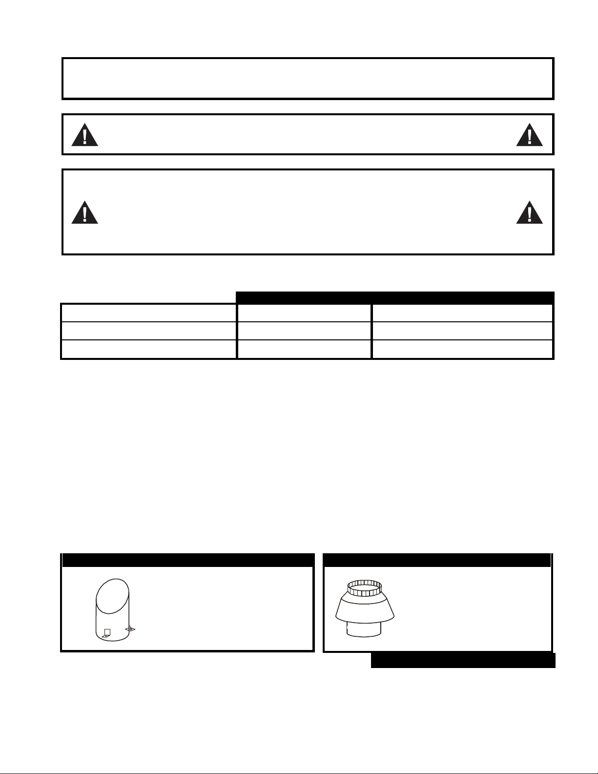
Figure #2
Draft Hood
(For use w/Direct venting)
Figure #1
Flue Diverter
(For use w/Collection Hood)
Figure #3
2. CLEARANCES:
3. SET UP: The oven must be installed in a well-ventilated area.
Your oven is packed standing on its back. Leave it on its back while unpacking. The skid may be left under the
oven for convenience in further handling. Unpack carefully to avoid damage to the oven. If concealed damage is
found, follow the instructions detailed in Section 1.
Keep the area around the oven free and clear of combustible materials. Do not store any materials on top of or
under any oven. The provision of an adequate air supply to your oven for ventilation and proper gas combustion is
essential. As a minimum, observe the clearances detailed in Section 2. Provide adequate ventilation and make up
air in accordance with local codes.
Fit the flue diverter supplied (See fig.1) into the hole located at top near the left rear of the oven and secure with
screws for installing the oven under a ventilation hood. For Direct Venting, Optional Draft Hood (Fig. 2) must be
placed into the hole. Direct Venting not available for European Community Countries. Local inspectors and
ventilation specialists should be consulted to make sure that the installation of the hood conforms to the local
codes and requirements (See fig. 3). In UK ventilation requirements as detailed in BS 5440 should be followed.
4
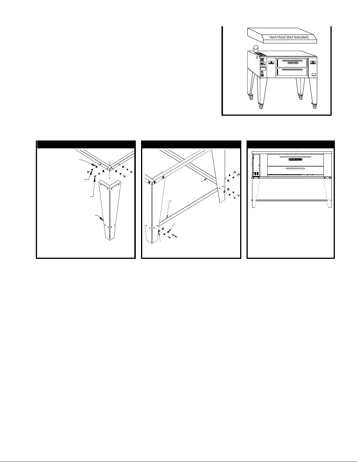
Figure #4
Figure #5
Figure #6
LEG (X4)
3/8-16 X 3/4"
#5 BOLT (16)
3/8 SPLIT LOCK
WASHER (16)
3/8 FLAT
WASHER (16)
SIDE
BRACE
(X2)
REAR
BRACE
3/8-16 X 3/4
#5 BOLT (12)
3/8 SPLIT
LOCK WASHER
(12)
3/8 FLAT
WASHER
(12)
Access to the bottom front door and left side control panel is required
for day to day operation of the oven and for servicing. Make sure that
these areas are kept unobstructed for easy access.
A. ASSEMBLING THE STAND:
Legs are shipped in a separate carton complete with mounting bolts.
a) Bolt four legs to the four of the stand using the supplied 3/8-16
x ¾ bolts, flat washers, and lock washers. (See fig. 4).
b) Bolt side braces and rear brace to legs using supplied 3/8-16 x
¾ bolts, lock washer, and flat washer. (See fig. 5).
c) Using proper lifting equipment, lower the oven from its back to
its bottom. Lift the unit and set on stand. (See fig.6).
d) Move the oven to its final location keeping the minimum clearances from the back of the oven to the wall.
This clearance is necessary for safe operation and to provide proper air-flow to the burner chamber.
B. INSTALLATION WITH CASTERS (OPTIONAL):
Four Casters (two with wheel brakes) and the mounting hardware is packed and included in the shipment if
ordered. Install casters with wheel brakes on the front of the unit. Stands with casters have a front
brace as well as a rear brace.
NOTE: Installation should be made with a connector that complies with the latest edition of the Standard for
Connectors for Movable Gas Appliances ANSI Z21.69 in the USA (CAN CGA-6.16 in Canada) and a quick
disconnect device that complies with the latest edition of the Standard for Quick Disconnect Devices for use with
gas fuel ANSI Z21.41 in the USA (CAN CGA 1-6.9 in Canada) and adequate means must be provided to limit the
movement of the appliance without depending on the connector and any quick disconnect device or its associated
piping.
The restraint should be attached to the rear legs of the oven on which casters are mounted. lf disconnection of the
restraint is necessary to move the oven for servicing needs; the restraint should be reconnected after the
appliance has been returned to its originally installed position.
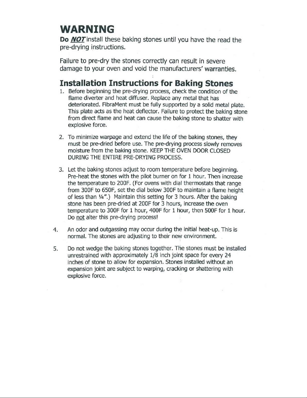
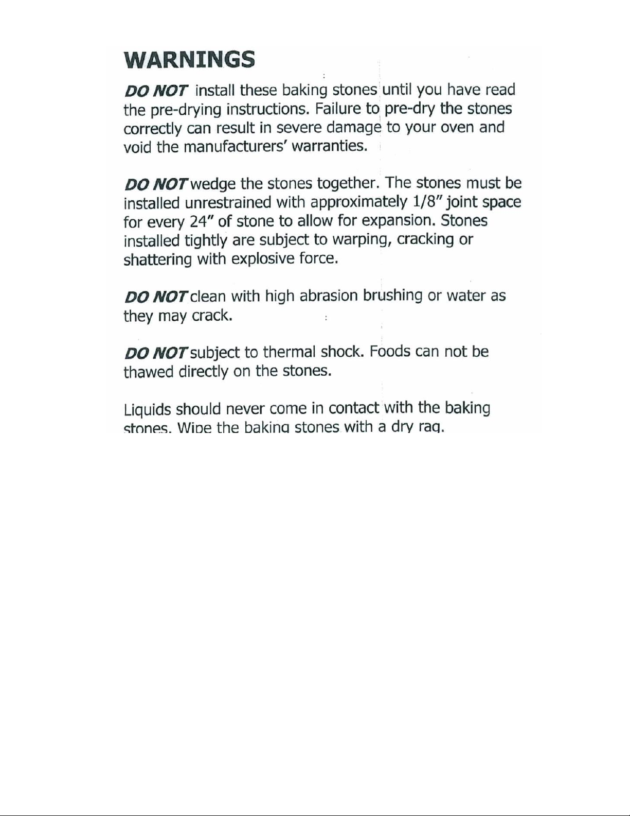
4. PIZZA DECK:
(a) Remove all packing material, samples, shims, etc. from the baking chamber leaving the two metal hearth
liner sheets on the baking chamber floor. Make sure that the two metal hearth liner sheets cover the entire
bottom of the chamber.
(b) The Vantage model has five FibraMent Pizza stones that are provided with the oven. This
material is heavy, and fragile, and should be handled carefully.
5
6
 Loading...