

Page 1

CONVEYOR OVEN SERVICE MANUAL
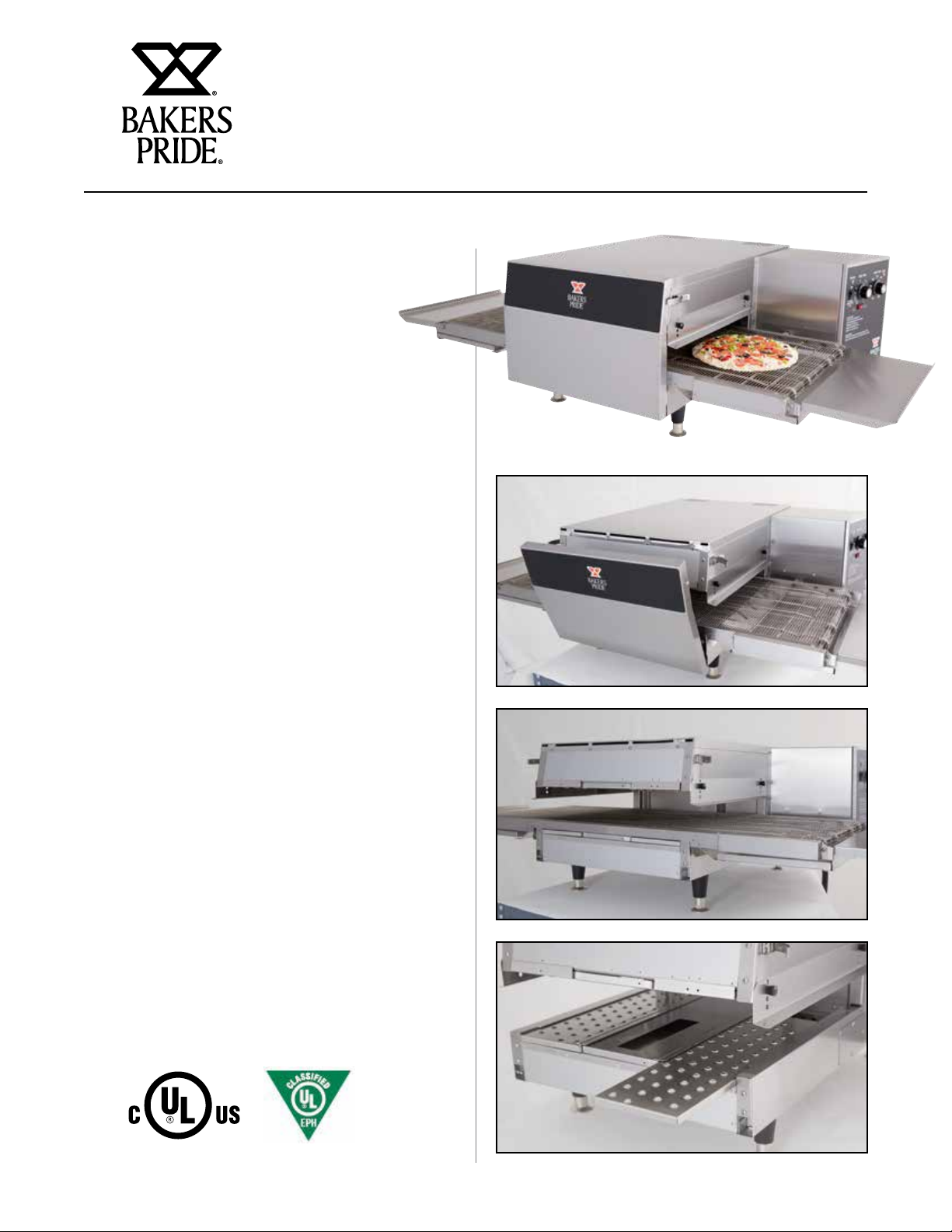
ICO-1848 CONVEYOR OVEN
SERVICE MANUAL
BUILT BY CRAFTSMEN. TESTED BY TIME®.
1
Page 2

Food Service Equipment Group
DEAR CUSTOMER
CONVEYOR OVEN SERVICE MANUAL
Bakers Pride Oven Company, LLC is a wholly owned
subsidiary of Standex International Corporation.
Congratulations on the purchase of your new Bakers
Pride® conveyor oven. By purchasing this new oven,
you have entered into a new era of cooking. With the
new technology and simplicity built into the combination
oven, you will receive excellent results in no time at all.
The oven’s ease and simplicity of operation will help you
realize savings in training dollars.
For more information, culinary support, and customer
service please contact 1- 800-927-6887. We will need
the following information to provide you the best service.
Appliance Model
S/N
Dealer
Installer
Date of Install
NOTICE
Please read the operations manual in full before
starting up the appliance to make sure all the
benefits and safety information is understood.
WARNING
California Residents Only
WARNING: This product can expose you to
chemicals including chromium which is known to
the State of California to cause cancer and birth
defects or other reproductive harm. For more
information go to www.P65Warnings.ca.gov.
Cooking Solutions Group
This equipment has been engineered to provide you with year round dependable
service when used according to the instructions in this manual and standard
commercial kitchen practices.
1307 N. Watters Road
Suite 180, Allen, TX
75013
9/18
www.bakerspride.com
western@standexcsg.com
central@standexcsg.com
eastern@standexcsg.com
2
800.431.2745
972.908.6100
Page 3

TABLE OF CONTENTS
CONVEYOR OVEN SERVICE MANUAL
SAFETY INFORMATION
Safety Information 4
SPECIFICATIONS
Design Features 5
Oven Specifications 6
INSTALLATION INFORMATION
Receiving 7
Set Up 7
Minimum Clearances 8
Electrical Connections 8
Terminal Block Configuration 9
CLEANING AND MAINTENANCE
Catalytic Converter 10
Jetplates And Air Returns 10
Oven Cavity 11
Oven Maintenance Guidelines 11
THEORY OF OPERATION
Impingement Air 12
Basic Operation 12
OVEN SYSTEMS
Blower Motor 13
Heater Elements 13
High Temperature Limit Switch 13
Jetplates/ Air Returns 13
Fuses 13
Reversing switch 14
24VDC Power Supply 14
Conveyor Speed Control 14
Conveyor Motor 14
Temperature Controller 14
Electrical Compartment Cooling Fan 14
Contactor 14
SPST Relay 14
TROUBLESHOOTING
Conveyor Issues 15
Heating Issues 16
WIRING DIAGRAMS
ICO-1848 (NC) 17
SERVICE PARTS
Part Numbers 18
Oven Illustrations 19-21
LIMITED WARRANTY INFORMATION 22-23
3
Page 4
SAFETY INFORMATION
CONVEYOR OVEN SERVICE MANUAL
DANGER
Not For Built-In Installation. For Use Only In
Professionally Staffed Commercial Kitchens.
Not For Use In Areas Accessible To The General
Public.
DANGER
Do not store or use gasoline or other flammable
vapors or liquids in the vicinity of this or any other
appliance.
WARNING
Improper installation, adjustment, alteration,
service or maintenance can cause property
damage, injury or death. Read the Installation,
Operating and Maintenance Instructions
thoroughly before installing or servicing this
equipment.
• Read all instructions before using the appliance
• This appliance must be grounded. Connect only
to a properly grounded outlet. See GROUNDING
INSTRUCTIONS located on page 8 of this manual.
• Install or locate this appliance only in accordance with
the provided installation instructions.
• Use this appliance only for its intended use as
described in the manual. Do not use corrosive
chemicals or vapors in this appliance. This type of
oven is specifically designed to heat, cook, or dry food.
It is no designed for industrial or laboratory use.
• As with any appliance, close supervision is necessary
when used with children.
• Do not operate this appliance if it has a damaged
cord or plug, if it is not working properly, or if its been
damaged or dropped.
• This appliance should be serviced only by qualified
service personnel. Contact the nearest authorized
service facility for examination, repair, or adjustment.
• Do not cover or block any openings on the appliance.
WARNING
Initial heating of oven may generate smoke or
fumes and must be done in a well-ventilated
area. Overexposure to smoke or fumes may cause
nausea or dizziness.
WARNING
To provide continued protection against electric
shock, connect to properly grounded outlets only.
CAUTION
This Device is to be Serviced Only by Properly
Qualified Service Personnel. Consult the Service
Manual for Proper Service Procedures.
• Do not store this appliance outdoors. Do not use this
product near water - for example, near a kitchen sink,
in a wet basement, near a swimming pool, or similar
location.
• Do not immerse cord or plug in water.
• Keep cord away from heated surfaces.
• Do not allow cord to hang over edge of table or
counter.
• To reduce the risk of fire in the oven cavity:
i) Do not over cook food. Carefully attend appliance
when paper, plastic, or other combustible materials
are placed inside the oven to facilitate cooking.
ii) Do not use the cavity for storage purposes. Do not
leave paper products, cooking utensils, or food in
the cavity when not in use.
4
Page 5
CONVEYOR OVEN SERVICE MANUAL
OVEN SPECIFICATIONS
Standard Features
• Simple rotary analog controls
• Top and bottom impingement air
• 6 Independent jet plates
• Balanced air flow for enhanced cooking performance
• 1 To 18 minute belt speed control
• 150˚ – 550˚ F (65˚ - 288˚ C) temperature range
• 18” (45 cm) Wide cook cavity will accommodate a
standard large pizza
• Removable crumb and landing platforms
• 304 Stainless steel cavity
• 1 Year warranty
Design Features
• A single rocker switch changes belt direction—no
need for service
• Easy to clean:
Two simple latches secure front access door which
allows the conveyor belt assembly to easily slide out
from the front. The drive gears and sprockets are not
exposed—no safety hazards. The six independent
jet plates easily slide out from the front for cleaning.
Smooth surfaces under the jet plates make cleaning
quick and safe.
• The ovens are designed to be stacked up to 3 units
high
• A ventless option is available to greatly reduce set-up
costs
• Single and three phase options are available, 208v
and 240v
5
Page 6
OVEN SPECIFICATIONS
CONVEYOR OVEN SERVICE MANUAL
Electrical Options
Model Volts Phase Cycle/Hz Amps Watts
ICO-1848 208 3 60 19 6,600
240 3 60 16 6,600
208 1 60 32 6,600
240 1 60 28 6,600
ICO-1848-NC 208 3 60 19 6,600
240 3 60 16 6,600
208 1 60 32 6,600
240 1 60 28 6,600
VOLTAGE 208V or 240V
FREQUENCY 60 HZ
SERVICE REQUIRED 20A 3ph 40A Single
PHASE Single or Three
TOTAL WATTAGE 6,600
HEATER WATTAGE 6,500
MODEL ICO-1848
RECEPTACLE REQUIRED 15-30P 3-ph 6-50P Single
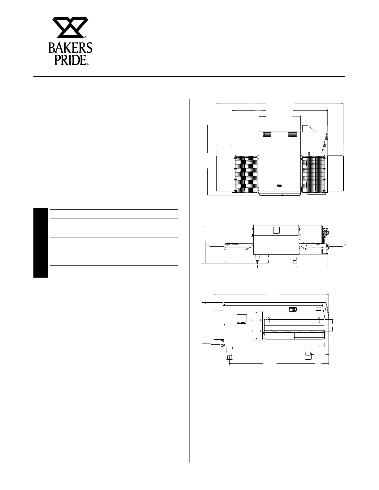
35.25”
(895 mm)
17.75”
(451 mm)
8”
(203 mm)
9” (229 mm)
64” (1626 mm)
48” (1219 mm)
21” (533 mm)
4” (102 mm)
17.25”
(438 mm)
15.25”
(387 mm)
Cook Chamber Dimensions
Height 3.4" (9 cm)
Width 20.8" (53 cm)
Depth 18.75" (48 cm)
Volume (cubic feet) 0.77 (0.02 m3)
Weight lbs. (unpackaged) 180 lbs.
(82 kg)
Stackable Yes, Max. of 3 Units
Exterior Dimensions
Height 17.6" (45 cm)
Width 63.8"(48" w/o
Platforms)
(162 -122 cm)
Depth 35.2" (89 cm)
Clearances
Top 5 inches (13 cm)
Sides 5 inches (13 cm)
Back 3 inches (8 cm)
12.5”
(318 mm)
35.25”
(337 mm)
24”
(610 mm)
5.25”
(133 mm)
6.25”
(159 mm)
3.5”
(9 cm)
6
Page 7

CONVEYOR OVEN SERVICE MANUAL
INSTALLATION INFORMATION
Receiving
Read the notice on the outside carton regarding damage
in transit. Damage discovered after opening the carton
is “CONCEALED DAMAGE.” Carrier must be notified
immediately to send an inspector and to furnish forms
for claims against the carrier.
When the oven arrives, it should consist of:
• One conveyor section
• Two crumb trays
• Two 8” landing platforms
• Two eyebrows
• Four eyebrow mount knobs
• Four jet plates
• Two air return plates
When unpacking the oven:
• Remove all packing material from unit
• Adequate air supply to the oven for ventilation is
essential. As a minimum, observe the clearances
detailed on page 8 (Minimum Clearances and
Approved Locations). Provide adequate ventilation and
make up air in accordance with local codes.
• The intake air is located at right side of the oven.
To prevent deteriorating the life and performance
of the oven, the intake air should be as cool as
possible and not preheated by other appliances.
• Allow sufficient clearance in front of the unit for the
door to open completely.
The oven arrives ready to install on a counter or table on
4” (10 cm) legs.
The ovens are designed to be stackable at a maximum
height of THREE units. To stack units, obtain a stacking
kit accessory (21940334) for each unit to be stacked.
Proper lifting methods must be used for safety. Each
oven must have a dedicated power supply. Only the
bottom oven receives the legs.
• Never lift the oven with only one person
• Retain instruction manual for future reference
Set Up/Mounting
Your oven will be packed sitting on its bottom. The skid
may be left under the oven for convenience in further
handling. Unpack carefully, avoiding damage to the
Stainless Steel front and/or trim. If concealed damage is
found, follow the instructions detailed in the Receiving
section above.
• Keep the area around the ovens free and clear of
combustible materials.
• Do not store any materials on top of or under any
oven.
• Do not position the unit so that hot air is drawn in
from fryers, grill, griddles or other appliances.
• A heat barrier the height of the oven will be
required if installed by a burner, fryer, or excessive
heat source.
7
Page 8
CONVEYOR OVEN SERVICE MANUAL
INSTALLATION INFORMATION
NOTICE
Local codes regarding installation vary greatly
from one area to another. The National Fire
Protection Association, Inc., states in its NFPA
96 latest edition that local codes are the
“authority having jurisdiction” when it comes
to requirements for installation of equipment.
Therefore, installations should comply with all
local codes.
Minimum Clearances and Approved Locations
Move the oven to its final location keeping the minimum
clearance from the back of the oven to the wall. This
clearance is necessary for safe operation and to provide
proper air flow.
The oven is designed for countertop installation and
is not recommended for built-in installation. The oven
requires adequate air to cool the electronic controls.
Operating the oven at elevated temperatures may
reduce reliability and overall performance of the oven.
If the oven is to be installed close to a major heat source
including char grills, griddles and fryers, minimum
clearances must be observed and a radiant/thermal heat
barrier installed between the heat source and the oven.
CAUTION
Do not REMOVE THE BACK VENT COVER. IT IS
PROVIDED TO MAINTAIN PROPER CLEARANCE
IF the oven IS SET WITH its back flat against the
wall. It will not operate properly unless the VENT
COVER IS IN PLACE.
Electrical Connection
Install according to the spacing requirements listed
in the installation section of this manual. We strongly
recommend having a competent professional install
this equipment. A licensed electrician should make the
electrical connections and connect power to the unit.
Local codes should always be used when connecting
these units to electrical power. In the absence of local
codes, use the latest version of the National Electrical
Code.
CAUTION
This Appliance Must be Grounded. Failure to do
so May Result In Electrical Shock and Death.
Adequate access to electrical connections, and side
panels must be provided for any future service. The
operator may be responsible for any additional labor
fees if required.
Minimal Clearances from Combustible and
Noncombustible Construction
Sides 5” (13 cm)
Rear 3” (8 cm)
Top 3” (8 cm)
No Surrounding Heat Source
Sides 12”
(30cm)
Rear 3” (8 cm)
Top 3” (8 cm)
Major Surrounding Heat Source;
e.g Fryers, Grills & Griddles
Sides 8” (20 cm)
Rear 3” (8 cm)
Top 3” (8 cm)
Minor Surrounding Heat Source;
e.g Heat Lamps & Warmers
CAUTION
The oven, when installed, must be electrically
grounded in accordance with local codes and/
or the latest edition of the National Electrical
Code ANSI/NFPA No. 70 in the USA (Canadian
Electrical Code CSA Standard C22.1, Part 1 in
Canada).
8
Page 9

CONVEYOR OVEN SERVICE MANUAL
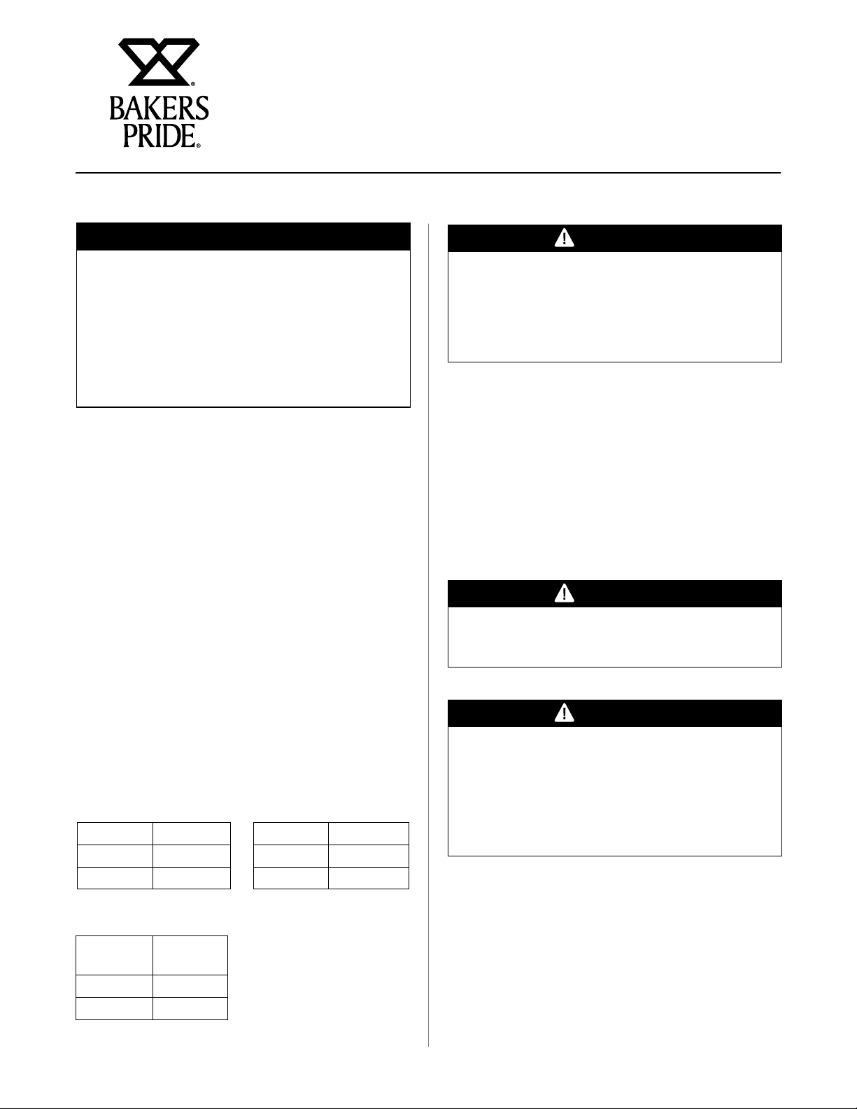
TERMINAL BLOCK CONFIGURATION
Terminal Block
The terminal block is used to simplify the conversion
between single and three phase applications in the
field. Two wires change positions on the output side
of the block (#55 & #39). Theese two wires are easily
identified by being striped in addition to their numbered
39
RED STRIPED
40
41
RED
RED
TERMINAL
BLOCK
RED STRIPED
RED
RED
55
56
57
T4 T3 T2 T1
T4 T3 T2 T1
OUTPUT
29
A2
CONTACTOR
A1
28
INPUT
T4 T3 T2 T1
36
L1
L2
38
ID tags.
RED STRIPED
RED STRIPED
TERMINAL
BLOCK
CONTACTOR
RED
RED
55
39
56
57
40
41
T4 T3 T2 T1
T4 T3 T2 T1
OUTPUT
29
A2
A1
28
INPUT
T4 T3 T2 T1
36
L3
L1
L2
RED
RED
38
SINGLE PHASE WIRING
CONFIGURATION
THREE PHASE WIRING
CONFIGURATION
9
Page 10

CONVEYOR OVEN SERVICE MANUAL
CLEANING AND MAINTENANCE
WARNING
Unit is not waterproof. To avoid electrical shock
or personal injury, DO NOT submerge in water. DO
NOT operate if it has been submerged in water.
DO NOT clean the unit with a water jet. DO NOT
steam clean or use excessive water on the unit.
CAUTION
Use mild detergent or soap solution for best
results. Abrasive cleaners could scratch the finish
of your unit, marring its appearance and making
it susceptible to dirt accumulation. DO NOT use
abrasive cleaners or a cleaner/sanitizer containing
chlorine, iodine, ammonia or bromine chemicals
as these will deteriorate the stainless steel and
glass material and shorten the life of the unit. Use
nylon scouring pads. Do not use steel wool.
Damage caused by unapproved cleaners may void the
manufacturers warranty.
The catalyst is located inside the unit and does not need
to be removed for cleaning.
Conveyor Section
It’s recommended that two people handle the assembly
during removal, cleaning, and installation. Remove the
door and slide the conveyor section forward. Take the
conveyor section to a sink and thoroughly clean with
warm water and a mild detergent or soap. Use a nylon
scouring pad or stiff nylon brush. The area around
the chain cover must be thoroughly cleaned. Do not
immerse the conveyor section in water.
Do not use steel wool.
Jetplates And Air Returns
Open the door and remove the jet plates and air returns
by pulling the jetplate forward. Take the panel to the
sink and thoroughly clean in warm water with mild
detergent or soap. Use a nylon scouring pad or stiff
nylon brush.
Catalytic Converter
The oven utilizes a catalytic converter system that
filters the cooking cavity air reducing grease and odors
from the room. This catalyst contains a microscopic
layer of a specific compound that reduces the ignition
temperature of grease. When the cavity air is moved
through the catalyst, the grease laden air is reduced to
CO2 and H2O. The catalyst is maintenance free and
will continue to operate without issue through the life
of the oven. However, proper care is required when
choosing the chemicals used to clean the cavity in order
to ensure longevity.
The catalyst is sensitive to particular compounds
found in common degreaser and industrial cleaners.
Potassium salts, phosphates, silicates, and other caustic
compounds can cause irreversible damage. This
damage can result in reduced catalyst performance
causing grease, smoke and odors to be in the room.
Bakers Pride provides an approved cleaner for purchase
and recommends any alternatives be checked to
determine their chemical content so not to cause
damage.
Do not use steel wool.
Oven Cavity
With the door open and the jet plates and air returns
removed, wipe out inside of the oven with a clean,
damp cloth. Use a nylon scouring pad dampened
with approved cleaning chemical or stiff nylon brush
to remove any baked on debris. Use a clean towel
dampened with clean water to thoroughly wipe out
inside to remove any cleaner residue and food particles.
Do not use steel wool.
WARNING
Keep cleaning fluids away from electrical wires,
light sockets, switches, and the control panel.
10
Page 11

CONVEYOR OVEN SERVICE MANUAL
CLEANING AND MAINTENANCE
Oven Exterior
To remove common dirt or product residue from
stainless steel, use ordinary soap and water (with or
without detergent) applied with a sponge or cloth. Dry
thoroughly with a clean cloth. Never use vinegar or
corrosive cleaner. Do not use chlorine based cleaners.
To remove grease and food splatter or condensed
vapors that have baked on the equipment, apply
cleaners to a damp cloth or sponge and rub cleanser
on the metal in the direction of the polished lines on
the metal. Rubbing cleanser as gently as possible in
the direction of the polished lines will not mar the finish
of the stainless steel. To remove discoloration, use a
non-abrasive cleaner. Never use a wire brush, steel or
abrasive scouring pads, scraper, file or other steel tools.
Never rub with a circular motion.
NOTICE
This appliance must be serviced by a factory
authorized service agent. Unauthorized service or
repairs may void the manufacturers warranty.
Oven Maintenance
• Power supply to the unit must be disconnected before
any service is performed.
• Most of the service on this unit can be performed from
the back and/or right side.
• It will be necessary to have access to the back of the
oven for service needs related to the blower motor.
However, for proper servicing, access to all sides is
recommended.
• A system wiring diagram is provided in the back of this
document as well as attached to the inside of the right
side oven panel.
• All servicing should be performed by a factoryauthorized technician only.
• For proper maintenance and repairs, call the factory
toll free (800.431.2745) for an authorized service
agency in your area.
CAUTION
This product, when stacked, has more than one
power-supply! Connection point. Disconnect all
power supplies before servicing.
11
Page 12

CONVEYOR OVEN SERVICE MANUAL
THEORY OF OPERATION
®
The Bakers Pride
intended to cook food by utilizing impingement air.
The cook time and cook temperature are individually
controlled to provide optimum settings for a variety of
items. Note that protein based foods are never to be
placed directly on the belt, but must be in a cooking
vessel capable of handling temperatures up to 550° F
(288° C).
ICO-1848 conveyor oven(-NC) is
Basic Operation
• Make sure the jet plates and air returns are
properly positioned
• Check that the door is installed correctly and the
locking clasps are closed
• Check that the conveyor section is in place and the
drive shaft is engaged with the motor shaft
WARNING
Placing protein based foods directly on the belt
may cause a fire hazard
The use of impingement allows the air to be strategically
placed in the cavity which greatly improves performance
and energy efficiency. The heated air is forced through
specifically designed holes which cause the air to
become turbulent creating a shrouding effect which
helps to keep moisture inside the product and providing
brownness and crispness when desired.
The use of impinged air greatly reduces overall cook
times. Common results are 2 - 3 times faster than a
conventional oven while still producing high quality
results.
• Install the crumb trays in the conveyor section
• Place the landing platforms (if desired)
• Set conveyor belt direction prior to power on
• When the conveyor oven is initially powered up for
use, it will take 10 to 15 minutes for it to reach set
operating temperature
• Set the desired cook temperature
• Set the desired cook time (this is the time it will
take the food product to travel the distance inside
the cooking chamber).
Four impingement jet
plates, one in each
corner of the cavity, top
and bottom
Two air return plates, one
each for top and bottom,
located in the center of the
cavity.
12
Page 13

OVEN SYSTEMS
CONVEYOR OVEN SERVICE MANUAL
Electrical Compartment Thermostat
The electrical compartment thermostat is a normally
open snap disk type switch that is mounted behind the
back electrical panel. The switch closes at 180˚ F. (82˚
C). When the oven’s On/Off switch is in the On position,
both the blower motor and cooling fan will engage.
When the power switch is placed in the Off position,
the fan operation will continue until the compartment
temperature drops below the 180˚ F. (82˚ C) set point.
NOTICE
To allow the cooling circuit to perform properly,
when the unit is powered down, 15 minutes
should be allowed to pass before the unit is
unplugged. The temperature in the unit will
continue to rise after the elements go off. In some
cases, this rise may be sufficient to engage the
cooling circuit several minutes after the unit is
placed in standby.
WARNING
Due to the design of the electrical circuit, the unit
is never truly in an “Off Mode”. When the power
switch is set to “standby” , electricity is still
present in the control panel. Always disconnect
the power from the wall before opening the
control panel
Blower Motor
The blower motor is proprietary and designed for this
particular application. Removal of the blower motor can
be performed from the rear without requiring fan wheel
removal. Care must be taken to ensure that the fan is
not damaged during removal and replacement.
Heater Element
The heating elements are located behind the catalyst
(when applicable) and in front of the fan wheel. The
ICO-1848 has one 6500-watt heater assembly. The
three elements in the assembly are fixed to a mounting
plate. The assembly is mounted on the right side of the
cook cavity. The elements are voltage specific to 208 or
240V but can be used for both single and three phase
applications. The heater element operation is controlled
by a contactor with the coil inputs from the temperature
controller.
High Temperature Limit Switch
The oven has an over temperature safety switch
located on the right side back of the unit. The switch
will interrupt all power to the conveyor oven if the
temperature in the cavity rises above 572˚ F (300˚ C).
After the oven cavity cools, the fault can be removed by
pressing the red button on the back of the unit.
Jetplates/ Air Returns, Top And Bottom
The impingement air is being pushed through the top
and bottom jet plates by the blower motor. The jet plates
and air returns are different and must be correctly
positioned for proper cooking performance. Improperly
installed jet plates and air returns will change the cooking
characteristics resulting in substandard cooking quality.
Each jet plate and air return is marked with a series of
holes that corresponds to the same indicator on the
front of the unit. In addition, there is a positioning post
inside the unit that corresponds to a notch on the back
of the jet plate/ air return. Improperly positioned jet
plates and air returns will not insert completely and will
not allow the door to latch.
Fuses
The oven uses a total of 3 fuses in the electrical system.
The two main fuses are located in the fuse block located
on the back panel. They are accessed by removing
the panel screw. The cover is held in place by a strong
magnet located inside the cabinet. It will take extra effort
to open the cover. Once disengaged from the magnet,
the cover rotates open from the bottom and is held in
place (it cannot be removed from the unit). These are
Class CC KLKR 3 amp fuses.
The other fuse is in the panel mount holder at the
bottom back of the unit. This fuse protects the conveyor
motor. It is a Class 3AG 3 amp fuse.
13
Page 14

OVEN SYSTEMS
CONVEYOR OVEN SERVICE MANUAL
Reversing Switch
The reversing switch located on the front panel changes
the direction of the conveyor belt. The direction should
be set when the unit is installed. If a change of direction
in the belt is wanted, it is highly suggested that the unit
be placed in standby and the switch changed. This will
prolong the life of the conveyor motor and controller.
24VDC Power Supply
The oven uses a 24vdc power supply to only power the
conveyor speed control board. This board is located
behind the controls on the front electrical panel and has
the 3 Amp fuse connected between it and the control
board. The 208/240 voltage is supplied from the On/Off
rocker switch.
Conveyor Speed Controller
The conveyor speed controller powers the conveyor
motor through a single Molex connector. The board uses
a potentiometer to control the desired speed which is
only sold with the board as an assembly. Once again,
the controller is powered by the 24VDC power supply.
The belt speed ranges between 1 - 18 minutes based
on the setting on the control panel.
Conveyor Motor
The conveyor motor is a proprietary motor designed for
use in this oven. It is a DC Motor using a gear reduction
drive to increase torque and speed accuracy. In the
event of an object being jammed in the conveyor, belt
assembly is protected from catastrophic damage from
the 3 amp fuse inserted in the power out put of the
power supply.
Temperature Controller
The temperature controller sends 208/240 AC coil
voltage to the contactor when calling for heat. The board
is powered by the On/Off switch and uses a Amber light
to indicate when the board is calling for heat. A separate
RTD is used to monitor the temperature in the cook
cavity.
Electrical Compartment Cooling Fan
The electrical compartment cooling fan is a 208/240V
axial fan located on the back of the compartment. The
fan pulls cooling air through the openings placed at the
bottom of the compartment and directs the air out of
the back. The fan operation is controlled by either the
On/Off rocker switch or by the electrical compartment
thermostat.
Contactor
The contactor is responsible for sending power to the
elements when the temperature controller calls for
heat. The controller sends 208/240 to the coil of the
contactor. The contactors are not voltage specific and
can be used with both single phase and three phase
power. If the oven’s voltage is converted in the field,
only the element needs to be replaced.
SPST Relay
Three single pole single throw relays are used to supply
one leg of power to the heater elements (L2). The coils
of these relays are powered by the output of the high
limit switch. When the oven is connected to power
and the high limit switch is not tripped, one side of the
elements will have power applied.
WARNING
Due to the design of the electrical circuit, the unit
is never truly in an “Off Mode”. When the power
switch is set to “standby” , electricity is still
present in the control panel. Always disconnect
the power from the wall before opening the
control panel
14
Page 15

TROUBLESHOOTING
CONVEYOR OVEN SERVICE MANUAL
Conveyor Not Moving
The conveyor motor is powered by the 24VDC power
supply through a 3 amp fuse. This fuse is designed to
limit the damage to the belt if an obstruction were to
enter the conveyor assembly. The motor is controlled
by the speed controller which uses an external
potentiometer to regulate the speed.
Remove Conveyor Assembly from Drive Shaft.
Does the Belt Move Freely by Hand?
Power Switch “On”
YES
Green LED Lit? Potentiometer Checks OK?
24VDC Across 79 and
86 of Speed Controller?
WARNING
Due to the design of the electrical circuit, the unit
is never truly in an “Off Mode”. When the power
switch is set to “standby” , electricity is still
present in the control panel. Always disconnect
the power from the wall before opening the
control panel
NO
208/240V Across
Switch Terminals?
3 Amp Fuse Open? Replace Failed
High Limit Switch
Tripped?
Incoming Power at
the Contactor?
Drive Motor
Checks OK?
Speed Controller
15
Page 16

TROUBLESHOOTING
CONVEYOR OVEN SERVICE MANUAL
No / Low Heat
The oven uses a single heater assembly consisting of
three individual elements for a total of 6500 watts. The
element operation (L1) is controlled by a contactor. The
other side of the 208/240V power (L2) is controlled by
three independent SPST relays. The coils of these relays
are powered by the high limit switch which makes this
circuit energized at all times when power is connected
to the oven (unless the high limit has tripped). The On/
Off switch does not control this entire circuit.
Power Switch “On”
YES
Amber LED Lit?
NO
208/240V Across 10
and 11 at Temp Controller?
208/240V Across 29
and 28 at the Contactor
YES
See RTD Chart Below
Due to the design of the electrical circuit, the unit
is never truly in an “Off Mode”. When the power
switch is set to “standby” , electricity is still
present in the control panel. Always disconnect
the power from the wall before opening the
control panel
Coil?
RTD Checks OK?
WARNING
208/240V Through the
Contactor?
Elements Correctly Wired
per Diagram?
NO
208/240V Across
Switch Terminals?
3 Amp Fuse Open?
High Limit Switch
Tripped?
Incoming Power at
the Contactor?
Replace Failed Temp
Control
208/240V Across Each
Element?
Replace Failed Heater
Element
RTD Chart OHM/Temp
32˚F (0˚C) 100.00 250˚F (121˚C) 146.49
300˚F (149˚C) 156.91
50˚F (10˚C) 103.90 350˚F (177˚C) 167.24
100˚F (38˚C) 114.68 400˚F (204˚C) 177.49
150˚F (65˚C) 125.37 450˚F (232˚C) 187.65
500˚F (260˚C) 197.71
212˚F (100˚C) 138.51 550˚F (288˚C) 207.69
16
Page 17

ICO-1848 CONVEYOR OVEN WIRE DIAGRAM
RELEASE FOR PRODUCTION
AMBER LIGHT
1514000
3 PHASE WIRING
CONFIGURATION
41
1
B
OF
REV.
SHEET
39
40
1
CONVEYOR
69
BLOWER
START
BLOWER
49
THERMOSTAT
1378040
23
74
MOTOR
21940421
CAPACITOR
21940215
MOTOR
21940205
70
50
SPEED
POT
68
1 2 3
CONVEYOR
48
47
24VDC
CONVEYOR
MOTOR
MOTOR
CONTROLLER
21940429
52
70
52
50
49
48
47
B
FUSE 3
POWER
SUPPLY
21940422
WHITE
RED
ORANGE
WIPER
67
69
68
25
7
27 22
1 2 3 4 5 6
26
74
3 AMP
4 3 2 1
HI LO
F/RLUM
B-B+
79
79
22 67
9
86
80
80
32
86
31
COOLING
FAN
1215610
2166 W
61
60
44
COM
55
RELAY
NO
39
55
T1
T2
T3T4
SINGLE PHASE
WIRING
CONFIGURATION
28
21
20
123
1
2
11
44
1475020
41
40
57
56
B
29
37
29
4
8
9
43
56
37
2166 W
NO
T1T2T3
A2
27
5
43
59
COM
21940428
CONTACTOR
26
678
3
5
4
2166 W
58
RELAY
A1
25
6
42
42
57
1475020
TERMINAL
BLOCK
28
9
COM
NO
21940385
38
L1
L2L3
36
L4
32
101112
16
21940200 - 208V
21940199 - 240V
46
45
RELAY
1475020
L1
L2
46
20 21
31
19
45
21
HIGH LIMIT
11
22
1380300
12
16
Cooking Solutions Group
FIELD SERVICE WIRING DIAGRAM
36
38
COVEYOR
DIRECTION
SWITCH
1305610
BAKERS PRIDE CONVEYOR OVEN
MODELS ICO-1848 and ICO-1848-NC
NONE
SCALE
SETBACK
BEND RADIUS
TOLERANCE-
19
208 & 240V 60Hz
DATE
DRAWN
BAKERS
.XX ±
.XXX ±±±
DECIMAL-
FRACTION-
PART NUMBER
Single and Three
Phase Power
12/8/16
DATE
GREG HAUN
APRVD.
APW
WYOTT
WHEN APPEARS, DEBURR EDGE
ANGLE-
21940433
FINISH
SPEC.
TYPE
SIZE
MATERIAL
STOCK NUMBER
DIVISION
PROGRAM NOTES
ECR
DATE
030817
120816
BY
GH
GH
DESCRIPTION
Removed 21940420 motor controller, fuse 3 to 3 amp,
part number changes to temp controller and contactor
B
A
REV
GREEN LIGHT
1513907
13
12
23
10
RTD
B
TEMPERATURE
CONTROLLER
62
63
ON/OFF
SWITCH
1301700
RTD
P9
RTD
8
21940444
P4
62
5
6
RTD
P8
P2
P5
14
FUSE 2
3 AMPS
FUSE
HOLDER
2
1
1504810
FUSE 1
3 AMPS
3
4
P10
41
T1
40
57
11
10
P1
63
14
T2
B
56
39
T3T4
55
21940428
A1
CONTACTOR
A2
29
38
L1
L1
36
L2L3
L2
L3
28
L4
17
Page 18

SERVICE PARTS
CONVEYOR OVEN SERVICE MANUAL
1. 21940444 Temp Control, RTD Input
2. 21940420A Potentiometer, Speed Controller
3. 1513907 Light, Indicator, Green, 250V
4. 1301700 Switch, Rocker, 16A, 250V, DPST
5. 1305610 Switch, Rocker, Lighted, SPST, 15A
6. 1514000 Light, Indicator 250V Amber
7. 8704600 Knob, Temp or Speed Control
8. 21940429 Controller, Speed, Conveyor Motor
9. 21940422 Power Supply, Conveyor Motor
10. 1380300 High Temperature Limit Switch
11. 1504830 Fuse, 3A, Class CC, 600V KLKR
12. 21940432 Fuse, 3A Conveyor Motor
13. 1215610 Fan, Cooling
14. 21940428 Contactor, 220V/240V, 4 Pole, 40A
29. 21940349 Jet Plate, Top Left (#1)
30. 21940379 Air Return Plate, Top
31. 21940350 Jet Plate, Top Right (#2)
32. 21940308 Jet Plate, Bottom Left (#3)
33. 21940342 Air Return Plate, Bottom
34. 21940307 Jet Plate, Bottom Right (#4)
35. 4883185 Probe, RTD
36. 21940200 Element, 208V 6500W
37. 21940199 Element, 240V 6500W
38. 21940440 Kit, Door Gasket Replacement (not
shown)
39. 21940441 Kit, Controller/ Speed Pot (not
shown)
40. 21940334 Stacking Kit (not shown)
15. R0180 SPST Relay, 40A
16. 21940215 Capacitor, Start, Blower Motor
17. 21940421 Motor, Conveyor, 24VDC
18. 783016 Knob-Threaded Stud 1/4-20 X 1/2
19. 21940256 Air Shutter
20. 21940436 Kit, Service, 1’ Belt Section
21. 21940437 Kit, Service, 2’ Belt Section
22. 21940438 Kit, Service, 3’ Belt Section
23. 21940439 Kit, Conveyor Assembly, ICO-1848
24. 21940288 Crumb Tray
25. 86295 Leg 4” Black
26. 1378040 Thermostat Disk, High Limit, NO,
180F
27. 21940205 Motor, Blower, 3400RPM
28. 21940362 Catalyst Field Install Kit
18
Page 19

SERVICE PARTS
CONVEYOR OVEN SERVICE MANUAL
1
2
3
4
5
6
7
13
8
9
10
11 12
19
Page 20

SERVICE PARTS
CONVEYOR OVEN SERVICE MANUAL
17
20
21
22
16
14
15
1918
26
27
23
24
25
20
Page 21

SERVICE PARTS
28
CONVEYOR OVEN SERVICE MANUAL
29
32
30
31
34
33
35
36 37
21
Page 22

CONVEYOR OVEN SERVICE MANUAL
BAKERS PRIDE LIMITED WARRANTY
What is Covered?
This warranty covers defects in material and
workmanship under normal use, and applies only to the
original purchaser providing that:
The equipment has not been accidentally or
intentionally damaged, altered or misused.
The equipment is properly installed, adjusted, operated
and maintained in accordance with National and local
codes and in accordance with the installation instruction
provided with the product.
The serial number rating plate affixed to the equipment
has not been defaced or removed.
Who is Covered?
This warranty is extended to the original purchaser and
applies only to equipment purchased for use in the
U.S.A.
Coverage Period
Full size gas and electric deck ovens: Two (2) year limited
parts and labor: Cyclone Convection Ovens: BCO Models:
One (1) year limited parts and labor; GDCO Models: Two
(2) year limited parts and labor; (5) year limited door
warranty. HD Series Models; BPHHP/BPHHPS/BPHMG/
BPHTG/BPHCB/BPHRB: Two (2) year parts and labor.
ICO-1848: Two (2) year parts and one (1) year labor.
radiants, stones and valves are covered for a period of
SIX MONTHS.
All Ceramic Baking Decks are covered for a period of
THREE MONTHS. The installation of these replacement
decks is the responsibility of the purchaser.
The extended cyclone door warranty years 3 through
5 is a parts only warranty and does not include labor,
travel, mileage or any other charges.
Exclusions
• Negligence or acts of God
• Thermostat calibrations after (30) days from
equipment installation date.
• Air and Gas adjustments.
• Light bulbs
• Glass doors and door adjustments
• Fuses
• Char broiler work decks and cutting boards.
• Tightening of conveyor chains.
• Adjustments to burner flames and cleaning of pilot
burners.
All other products: One (1) year limited parts and labor.
Warranty period begins the date of dealer invoice to
customer or ninety (90) days after shipment date from
Bakers Pride - whichever comes first.
Warranty Coverage
This warranty covers on site labor, parts and reasonable
travel time and travel expenses of the authorized service
representative up to (100) miles, round trip, and (2)
hours travel time. The purchaser, however shall be
responsible for all expenses related to travel, including
time, mileage and shipping expenses on smaller counter
models that may be carried into a Factory Authorized
Service Center, including the following models: PX-13,
PX-16, P18, and BK-18.
Exceptions
All removable parts in Bakers Pride® cooking
equipment, including but not limited to: burners, grates,
• Tightening of screws or fasteners.
• Failures caused by erratic voltages or gas supplies.
• Unauthorized repair by anyone other than a Bakers
Pride Factory Authorized Service Center.
• Damage in shipment.
• Alteration, misuse or improper installation.
• Thermostats and safety valves with broken capillary
tubes.
• Accessories - spatulas, forks, steak turners, grate
lifters, oven brushes, scrappers, peels, etc.
• Freight = other than normal UPS charges.
• Ordinary wear and tear.
22
Page 23

CONVEYOR OVEN SERVICE MANUAL
BAKERS PRIDE LIMITED WARRANTY
Installation
Leveling and installation of decks, as well as proper
installation and check out of all new equipment per appropriate installation and use of materials - is
the responsibility of the dealer or installer, not the
manufacturer.
Replacement Parts
Bakers Pride genuine Factory OEM parts receive a
(90) day materials warranty effective from the date of
installation by a Bakers Pride Factory Authorized Service
Center.
This warranty is in lieu of all other warranties, expressed
or implied, and all other obligations or liabilities on the
manufacturers part. Bakers Pride shall in no event
be liable for any special, indirect or consequential
damages, or in any event for damages in excess of the
purchase price of the unit. The repair or replacement of
proven defective part shall constitute a fulfillment of all
obligations under the terms of this warranty.
How to Arrange for Service
All warranty service should be coordinated through
the Technical Service Department at Bakers Pride.
You can reach us, toll free, at 1-800-431-2745. All
warranty service calls will be immediately dispatched
by Bakers Pride to the local Factory Authorized Service
Center in your area. When requesting service or parts
identification, always specify:
• Model Number
• Serial Number
• Type of Gas or Voltage
• Phase or Wattage
• Date Code
23
Page 24

Cooking Solutions Group
The Standex Food Service Equipment Group (FSEG) is a manufacturer of innovative commercial
food service equipment offering a wealth of refrigeration and cooking expertise. Products
include walk-in coolers and freezers; hot and cold display cabinets, cases, and storage systems;
commercial ovens, rotisseries, and cooking equipment; and rotary vane pumps.
Ask your sales representative about how the power of all Standex brands can work for you.
www.standex.com/segments/food-service
Be sure to keep up with new product
announcements and events on social media!
24
 Loading...