

Affix Serial Number Sticker Here
User Manual UM-048
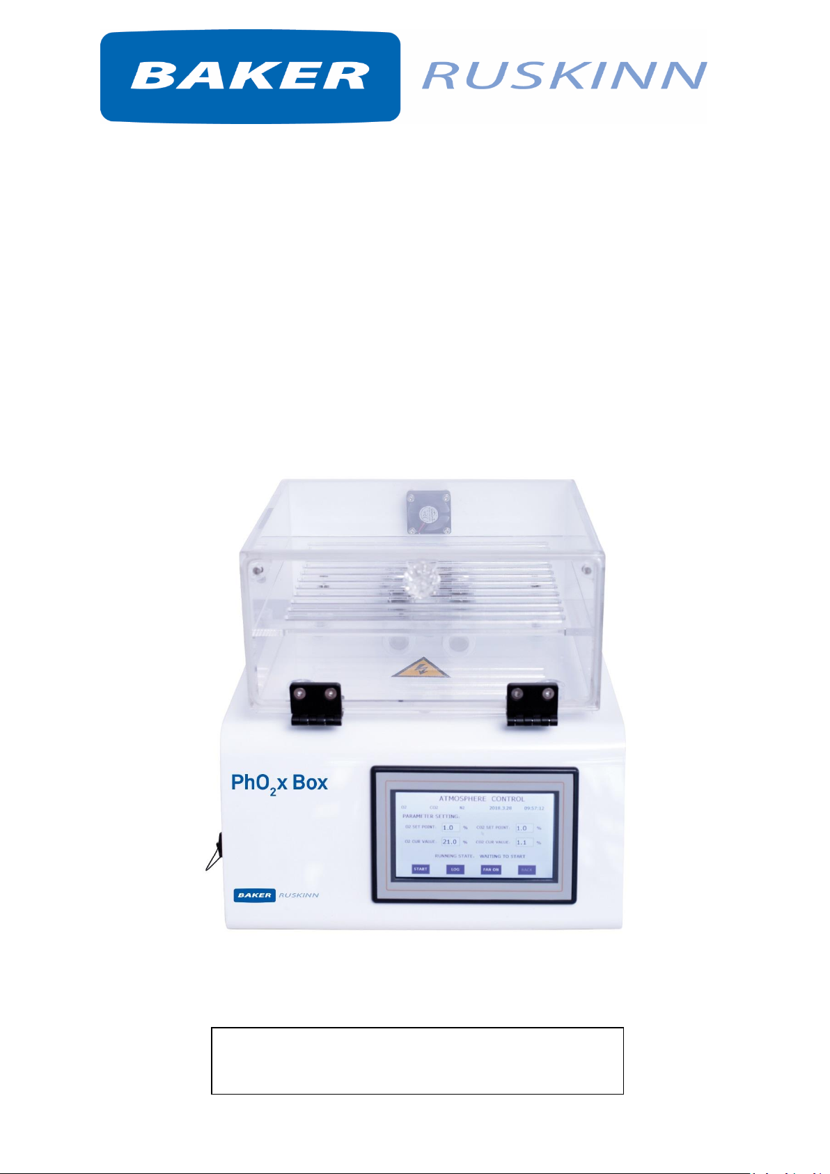
PhO2xBox
Cell-Culture Chamber System
PhO2xBox

i
Unit 8&9 / York Park / Bridgend, United Kingdom / CF31 3TB
+44 (0) 1656 645688 / Fax: +44 (0) 1656 667966 / sales@ruskinn.com /
www.bakerruskinn.com
CONTENTS
TABLE OF FIGURES ................................................................................................................................... I
TABLE OF TABLES .................................................................................................................................... II
INTRODUCTION ....................................................................................................................................... 3
SAFETY INSTRUCTIONS ............................................................................................................................ 4
REGULATORY COMPLIANCE .................................................................................................................... 5
SYMBOLS ............................................................................................................................................. 6
TRANSPORT AND STORAGE .................................................................................................................... 7
LOCATION AND HANDLING OF THE PHO2XBOX ...................................................................................... 7
ENVIRONMENTAL OPERATING CONDITIONS .......................................................................................... 7
SERVICE REQUIREMENTS ........................................................................................................................ 8
ELECTRICAL SUPPLY REQUIREMENTS ................................................................................................. 8
GAS SUPPLY REQUIREMENTS .............................................................................................................. 8
PHO2XBOX OVERVIEW ............................................................................................................................ 9
SETTING UP THE GAS CONTROLLER AND CULTURE CHAMBER ............................................................ 13
SETTING UP THE CELL CULTURE CHAMBER ON A LABORATORY BENCH .......................................... 13
FOR INSTALLATION INSIDE A WORKSTATION (SCI-TIVE OR INVIVO2) OR CO2 INCUBATOR .............. 14
USING THE GAS CONTROLLER ............................................................................................................... 17
THE TOUCH SCREENS ............................................................................................................................ 19
START UP SCREENS ........................................................................................................................... 19
MAIN SCREENS .................................................................................................................................. 19
ATMOSPHERE CONTROL SCREEN ...................................................................................................... 20
RE-SETTING THE O2 AND CO2 VALUE DURING OPERATION ............................................................... 22
WARRANTY INFORMATION................................................................................................................... 26
DISPOSAL INFORMATION ...................................................................................................................... 27
CONTACT DETAILS ................................................................................................................................. 28
TABLE OF FIGURES
Figure 1: Blue Tube ............................................................................................................................... 10
Figure 2: Mains Lead ............................................................................................................................. 10
Figure 3: Signal Lead ............................................................................................................................. 10
Figure 4: Gas Controller (With air pump).............................................................................................. 10
Figure 5: N2 Gas Hose ............................................................................................................................ 11
Figure 6: CO2 Gas Hose ......................................................................................................................... 11
Figure 7: Cell Culture Chamber (Small QTK-A01) .................................................................................. 11
Figure 8: Cell Culture Chamber (Large QTK-A02) .................................................................................. 11
Figure 9: Cell Culture Chamber (Large QTK-AB02)................................................................................ 12

ii
Unit 8&9 / York Park / Bridgend, United Kingdom / CF31 3TB
+44 (0) 1656 645688 / Fax: +44 (0) 1656 667966 / sales@ruskinn.com /
www.bakerruskinn.com
Figure 10: Rear of Cell culture chamber ............................................................................................... 13
Figure 11: Rear of Cell culture multi chamber ...................................................................................... 13
Figure 12: Rear of gas controller ........................................................................................................... 14
Figure 13: Outside view of InvivO2 showing Universal Multi-Cable Gland ........................................... 14
Figure 14: Inside view of InvivO2 showing Universal Multi-Cable Gland .............................................. 15
Figure 15: Black frame and blue plug.................................................................................................... 15
Figure 16: Multi-cable Gland................................................................................................................. 16
Figure 17: Pneumatic schematic ........................................................................................................... 16
Figure 18: Front View ............................................................................................................................ 17
Figure 19: Left View .............................................................................................................................. 17
Figure 20: Right View ............................................................................................................................ 17
Figure 21: Rear View ............................................................................................................................. 17
Figure 22: Rear View (Multi version) .................................................................................................... 18
Figure 23: Top View .............................................................................................................................. 18
Figure 24: Screen 1 – Logo screen ........................................................................................................ 19
Figure 25: Screen 2 – Main screen ........................................................................................................ 19
Figure 25: Multi chamber version only – Chamber selection screen ................................................... 20
Figure 25: Multi chamber version main screen .................................................................................... 20
Figure 26: Screen 3 - Atmosphere Control Screen ................................................................................ 20
Figure 27: Screen 4 – Level SET POINT Screen ...................................................................................... 21
Figure 28: Screen 5 – Atmosphere Control Screen ............................................................................... 22
Figure 29: Screen 6 – Hypoxic Cycle Menu Settings ............................................................................. 22
Figure 30: Screen 7 – Trend Log ............................................................................................................ 23
Figure 31: Screen 8 – Engineer Mode Screen ....................................................................................... 23
TABLE OF TABLES
Table 1: List of Symbols ........................................................................................................................... 6
Table 2: Electrical Service Requirements ................................................................................................ 8
Table 3: Standard Gases .......................................................................................................................... 8

3
INTRODUCTION
Please read this manual carefully before using the PhO2xBox and familiarise yourself with all aspects
of using the workstation. The Baker Company (Baker) or Ruskinn Technology Ltd (Ruskinn) does not
accept responsibility for accidents to personnel or damage to the PhO2xBox workstation resulting from
incorrect use.
The PhO2xBox comprises of a Gas Controller and a Cell-Culture Chamber has been specifically designed
and developed to meet the requirements of all laboratories.
The system has built in gas control with Oxygen and Carbon Dioxide sensors to enable constant
monitoring of the atmosphere. Hypoxic conditions are created using Nitrogen (N2), Carbon Dioxide
(CO2) and Compressed Air (O2) (or 25% Oxygen in Nitrogen) to achieve the desired atmosphere. The
user can select the Oxygen concentration from 0.1% to 20.9%, and Carbon Dioxide concentrations
from 0.1% to 30.0%.
Many unique features of the PhO2xBox workstation are covered in detail in this manual. It is
recommended that the user be fully conversant with the instruction and procedures, and that the
operator familiarises themselves with all aspects and functions of the system before it is commissions
to maintain optimum performance.

4
SAFETY INSTRUCTIONS
Please read this manual carefully and familiarize yourself with all aspects of the Cell-Culture Chamber
System.
The System comprises a Gas Controller and a Cell-Culture Chamber.
Baker and/or Ruskinn does not accept responsibility for accidents to personnel or damage to the CellCulture Chamber System resulting from incorrect use.
The mains appliance coupler and plug are the AC mains supply isolation device and must be easily
accessible when installed.
In case of emergency disconnect the Gas Controller from the AC Mains Outlet.
Ensure that the connecting cable is not squeezed or bent when the System is being installed or moved.
All installation work and adjustments to the System must be carried out by qualified personnel.
Work performed by persons with insufficient technical knowledge may adversely affect the
performance of the system or cause physical injury or damage to the equipment.
All servicing and repairs must be carried out by a qualified customer service engineer.
Only genuine spare parts must be used.
All gas cylinders must be adequately secured before connection to the System.
CAUTION: Asphyxiation Risk
The PhO2xBox uses Nitrogen (N2) and Carbon Dioxide (CO2) as part of normal use with the volume
released externally is inconsequential. In the event of a leak or malfunction this gas release may
become excessive. DO NOT OPERATE this unit in a SMALL ENCLOSURE such as a small room or walkin closet. An accidental release of Nitrogen or Carbon Dioxide could create an asphyxiating
atmosphere in a small space.
If the equipment is not use in a manor specified by the manufacture, the protection provided by the
equipment may be impaired.
Failure to adhere to these safety instructions could cause serious injury and will invalidate the
workstation warranty. Ruskinn technology limited accepts no responsibility for any accident, injury or
loss caused by unsafe operation of the workstation.

5
REGULATORY COMPLIANCE
WEEE:
This equipment must be disposed of in accordance with the Waste from Electrical and Electronic
Equipment (WEEE) Directive
This product must not be treated as household waste. Instead, it shall be handed over to an
appropriate collection point for the recycling of electrical and electronic equipment.
If in doubt, please return this equipment to Ruskinn Technology Ltd who will correctly dispose of it for
you. We strongly recommend that this product is returned to RTL at the end of its useful life.

6
Symbols
Before using the PhO2xBox, please ensure that you are familiar with the symbols.
Symbol
Meaning
Refer to user manual.
~
Alternating current
O
Off I On
Functional Earth Connection
Protective Earth Connection
Caution, do not remove covers. No end user serviceable parts behind covers.
Please refer to this manual in all cases where this symbol appears, in order to
find out the nature of the Potential Hazard and actions to be taken in order to
avoid the Hazard.
Warning, this equipment contains high voltage circuitry.
Contains material or substances that may be hazardous to human health. Please
refer to your local biohazardous material handling procedure for further advice
on the handling and disposal of these items.
PhO2xBox contains hazardous components and must not be disposed of at a
household waste site. Instead it should be taken to the appropriate collection
point for the recycling of electrical and electronic equipment.
USB socket
Date of manufacture in format
YYYY MM
Table 1: List of Symbols

7
TRANSPORT AND STORAGE
When not in use, the PhO2xBox controller box & cell culture chamber must only be stored within a
temperature of between 0°C and 30°C
Storage outside of this range may damage the gas controller.
LOCATION AND HANDLING OF THE PHO2XBOX
The PhO2xBox should only be installed or relocated by a qualified engineer. To arrange installation or
relocation please contact your local distributor.
The mains appliance coupler and plug are the AC mains supply isolation device and must be easily
accessible.
ENVIRONMENTAL OPERATING CONDITIONS
The PhO2xBox should only be operated under the following environmental conditions:
• Temperature – Between 15⁰C and 30⁰C
• Humidity – Between ambient and 90% RH, Non-Condensing
The workstation must be located in a well-ventilated area.

8
SERVICE REQUIREMENTS
Electrical Supply Requirements
The Gas Controller must be connected to a mains power supply. A power cord is supplied to connect
the workstation to the mains supply. If an alternative power cord is used is must be rated appropriately
for the power requirements of the Gas Controller, refer to Table 2. The Gas Controller must be
connected to a protective earth.
To ensure safe operation of the system, it must be connected to a supply of the correct voltage and
frequency as stated on the rating label shown.
The mains supply voltage fluctuations must not exceed +/- 10% of the nominal mains voltage.
Voltage Range
Frequency
Rated Current
Rated Power
220±20V
50Hz
0.1A
35W
110±10V
60Hz
0.1A
25W
Table 2: Electrical Service Requirements
Gas Supply Requirements
The gas regulator should provide a minimum supply pressure of 2 bar gauge. The maximum supply
pressure permissible is 3 bar gauge. See Table 4 below. A supply pressure greater than this will damage
internal components of the gas mixer and will invalidate the warranty.
Gas
Symbol
Specification
Regulator
Output
Pressure
Nitrogen
N2 Oxygen Free
(Industrial or medical)
2 to 3 bar
Carbon Dioxide
CO2 100%
(Industrial or medical)
2 to 3 bar
Table 3: Standard Gases
For the gas supply we recommend direct connections of the gas cylinder regulator to ensure minimal
pressure drops and flow rate restrictions. Only the above stated gases are to be used with the system.
Failure to comply with this may cause the product to become hazardous.
Only the above stated gases are to be used with the workstation. Failure to comply with this may
cause the product to become hazardous.

9
PHO2XBOX OVERVIEW
Background
The System comprises a Cell Culture Chamber , which comes in two sizes (Small and Large) and
different colours (Black & Transparent), and a Gas Controller. The Gas Controller is connected to the
Cell Culture Chamber. The Cell Culture Chamber can hold cell culture flasks and 6, 12, 24 or 96 well
plates. The gas concentration of the Cell Culture Chamber can be changed automatically by using the
touchscreen on the Gas Controller.
Hypoxic conditions are created inside the Culture Chamber by using Nitrogen (N2), Carbon Dioxide
(CO2) and laboratory air (which is sucked into the Gas Controller via an Air pump). The user can select
the Oxygen concentration from 0.3% to 20.0%, and the Carbon Dioxide concentration from 0.3% to
20.0%. The Cell Culture Chamber is well-sealed so it can reach the desired culture conditions quickly.
Built in Oxygen and Carbon Dioxide sensors enable constant monitoring of the atmosphere inside the
Cell Culture Chamber.
The Cell Culture Chamber can be placed into a CO₂ incubator, CO₂/O₂ incubator or Physoxia/Hypoxia
workstation.
CONTENTS (QTK-AO1/AO2)
1 mains lead
1 signal lead
1 blue tube (1m)
1 black gas hose (CO2) (3m)
1 blue gas hose (N2) (3m)
1 Cell Culture Chamber (Large QTK-AO2 or Small QTK-AO1)
Large: W x D x H (mm)= 360 x 300 x 230
Small: W x D x H (mm)= 340 x 300 x 160
1 Gas Controller (with air pump built in)

10
Figure 1: Blue Tube
Figure 2: Mains Lead
Figure 3: Signal Lead
Figure 4: Gas Controller (With air pump)

11
Figure 5: N2 Gas Hose
Figure 6: CO2 Gas Hose
Figure 7: Cell Culture Chamber (Small QTK-A01)
Figure 8: Cell Culture Chamber (Large QTK-A02)

12
Figure 9: Cell Culture Chamber (Large QTK-AB02)

13
SETTING UP THE GAS CONTROLLER AND CULTURE CHAMBER
Setting up the cell culture chamber on a laboratory bench
The Cell Culture Chamber can be placed adjacent to or on top of the Gas Controller.
Connect the blue tube to InA on the Cell Culture Chamber and OutA on the Gas Controller.
Connect the signal lead to InB on the Cell Culture Chamber and OutB on the Gas Controller.
Figure 10: Rear of Cell culture chamber
Figure 11: Rear of Cell culture multi chamber

14
Figure 12: Rear of gas controller
Use the blue hose to connect N2 on the Gas Controller to the N2 gas cylinder and the black hose to
connect CO2 on the Gas Controller to the CO2 cylinder.
Connect the mains lead to the right port shown on Gas Controller.
Open gas cylinders and turn the gas controller power on.
For installation inside a workstation (SCI-tive or InvivO2) or CO2 Incubator
Place Cell Culture Chamber in desired Workstation or Incubator.
Place the Gas Controller adjacent to the Workstation or Incubator.
Locate Universal Multi-Cable Gland on left side panel of Workstation or Incubator.
Figure 13: Outside view of InvivO2 showing Universal Multi-Cable Gland

15
Figure 14: Inside view of InvivO2 showing Universal Multi-Cable Gland
Figure 15: Black frame and blue plug
Unscrew inside black frame of the Universal Multi-Cable Gland and remove the blue plug. The Plug
can contain up to 6 pre-drilled holes depending on how it was ordered. Additional holes can also be
drilled by user.
Connect the blue tube to InA on the Cell Culture Chamber and OutA on the Gas Controller. The blue
tube has to be put through the Universal Multi-Cable gland.
Connect the signal lead to InB on the Cell Culture Chamber and OutB on the Gas Controller. The lead
has to be put through the Universal Multi-Cable gland.
Ensure that the blue tube and signal cable goes through the Universal Multi-Cable Gland into the plug
from the inside.

16
Figure 16: Multi-cable Gland
Use the blue hose to connect N2 on the Gas Controller to the N2 gas cylinder and the black hose to
connect CO2 on the Gas Controller to the CO2 cylinder.
Connect the mains lead to the right port shown on Gas Controller.
Figure 17: Pneumatic schematic
Open gas cylinders and turn the Gas Controller power on.

17
USING THE GAS CONTROLLER
Gas Controller
The Gas Controller is shown as follows.
Figure 18: Front View
Figure 19: Left View
Figure 20: Right View
Figure 21: Rear View

18
Figure 22: Rear View (Multi version)
Figure 23: Top View

19
THE TOUCH SCREENS
Start up screens
When the unit is first powered a Logo Screen (Screen 1) will appear and then will be replaced by the
Main Screen (Screen 2).
Figure 24: Screen 1 – Logo screen
Main screens
From this menu you will be able to access the Main screen below.
Figure 25: Screen 2 – Main screen
The multi chamber version chamber selection must first be made.

20
Figure 26: Multi chamber version only – Chamber selection screen
Once chamber has been selected the main menu is then displayed with the currently active chamber
displayed in the top left corner.
Figure 27: Multi chamber version main screen
Atmosphere Control Screen
Pressing the “Atmosphere Control” bar on Screen 2 will open up the settings screen shown in Screen
3.
Figure 28: Screen 3 - Atmosphere Control Screen

21
O₂ and CO₂ set point can be changed by pressing O2 SET POINT or CO2 SET POINT. A pop-up will
appear for the new setting to be selected, as shown in Screen 4. Press Enter once the desired value
of O2 is selected.
Figure 29: Screen 4 – Level SET POINT Screen
Repeat for CO2.
Once O₂ and CO₂ set-points have been selected press the START button in the bottom left of the
screen to start the gas control.

22
Re-setting the O2 and CO2 value during operation
To re-set the value during operation, press the “stop” button, change the value, and press the
“start” button. The new value will now become the Set Point.
Figure 30: Screen 5 – Atmosphere Control Screen
Hypoxic Cycle Menu Settings
The Hypoxic Cycle menu is accessed from Screen 2 to allow for dynamic changing of the Oxygen and
Carbon Dioxide levels over fixed time periods. Screen 6 shows the initial screen display for
continuous cycling for up to 4 set-point.
Figure 31: Screen 6 – Hypoxic Cycle Menu Settings
The user can set hypoxic cycle on the left side of screen 6. The timing values define how long the
Oxygen and Carbon Dioxide levels are maintained for once they have been achieved. This means
that there is a time period between the steps that cannot be set as it is dependent on the difference
between the set-points within the gas control software.
Pressing on any of the values will bring up a dialogue box to enter the required setting. If only 2
values are required for the cycling then set step 1 and 2 as required, then set step 3 times period to
0 minutes with the O₂ and CO₂ set-points the same as step 2.
Once the setting is correct then press the start button to begin the cycling. At this point the start
button will change to a Stop button. The continuous cycling will stop by pressing the Stop button.
The left side of the screen is the current status of hypoxic cycle.

23
Data Trend Log
The Data Trend Log screen can be accessed from the LOG button on screen 6.
Screen 7 shows the Trend Log display. The earliest recorded data will be displayed. The window can
be scrolled through on the control screen. To view previous data, the USB is to be removed and
connected to a computer. The USB can capture approximately 6 months of data.
Delete: Press delete button and the data will disappear from the system.
USB Save: Press USB Save button and the data log will downloaded to a USB.
Figure 32: Screen 7 – Trend Log
Engineer Mode Screen
To set the control parameters, enter the Engineer Mode screen. Entry to the Engineer Mode screen
is available when the time shows 29s-30s or 59s-00s. Double click on the corner of the top right of
the atmosphere control screen, and then you will enter the engineer screen. Press the value, and a
pop-up will appear for the new setting to be selected, then press “save” button and “back” button,
and you will return to the running mode.
Figure 33: Screen 8 – Engineer Mode Screen

24
Parameter Ranges and Meanings
Offset: range is 0.1-1.0%, when the set point and current value difference is less than offset the unit
enters the intermittent adjustment mode.
Deadband setting: range is 0-0.5%, for example when the deadband setting is 0.2% and O2 set point
is 5.0%, when the current value is 4.8%-5.2%, no gases will be injected to adjust the concentration.
Switch on: range 1-20s, means injecting time when the unit enters the intermittent adjustment
mode.
Switch off: range 1-20s, means rest time when the unit enters the intermittent adjustment mode, for
example if set switch on at 2s and switch off at 10s, the Gas Controller will inject gas at 2s and rest at
10s.
Recording time: Range 1-10s, means record the set time interval between 1 and 10 seconds. For
example, set recording time 2s, means it will record once every 2 seconds.
Date and time: to change the date and time, press “setting time” button, and then enter a windows
screen, choose the date and time, press back to return to the running mode.

25
OTHER INFORMATION
The material of the Gas Controller, the Cell Culture Chamber and the shelf is made of acrylic, The
maximum temperature that the chamber can withstand up to 60℃.
The Cell Culture Chamber is connected to Gas Controller, which contains O₂ and CO₂ sensors.
A dish of distilled water can be installed in the culture chamber to increase humidity
Cleaning: Use special cleaning kit supplied by Baker Ruskinn (code 262-345) or < 70% ethanol wiping,
please do not use ultraviolet irradiation.

26
WARRANTY INFORMATION
Ruskinn Technology Limited warrants for the applicable time period that the PhO2xBox will
substantially perform in accordance with the user documentation. The terms of this Agreement do
not affect or prejudice the statutory rights of a consumer acquiring the Ruskinn Technology Limited
PhO2xBox otherwise than in the normal course of a business.
THIS WARRANTY DOES NOT APPLY IN THE FOLLOWING CIRCUMSTANCES:
(A) IF THE Ruskinn Technology Limited PhO2xBox HAS BEEN REPAIRED BY PERSONS NOT AUTHORIZED
BY Ruskinn Technology Limited; OR
(B) THE Ruskinn Technology Limited PhO2xBox and associated accessories/peripherals HAVE BEEN
ALTERED, MODIFIED, OR MISUSED; OR
(C) THE Ruskinn Technology Limited PhO2xBox IS USED WITH NON- Ruskinn Technology Limited
COMPONENTS; OR
(D) THE Ruskinn Technology Limited PhO2xBox OR A COMPONENT IS USED FOR OTHER USES (FOR
EXAMPLE USE WITH OTHER CIRCUIT BOARDS OR SOFTWARE) OR
(E) THE Ruskinn Technology Limited PhO2xBox HAS NOT BEEN MAINTAINED OR USED IN ACCORDANCE
WITH THE INSTALLATION AND USER GUIDE. UNLESS PROHIBITED BY LAW, THIS WARRANTY IS MADE
IN LIEU OF ALL OTHER WARRANTIES, EXPRESS OR IMPLIED, INCLUDING BUT NOT LIMITED TO THE
IMPLIED WARRANTY OF FITNESS FOR A PARTICULAR PURPOSE, THE IMPLIED WARRANTY OF
MERCHANTABILITY, OR ANY IMPLIED WARRANTY ARISING OUT OF A COURSE OF DEALING OR OF
PERFORMANCE, CUSTOM OR USAGE OF TRADE. Ruskinn Technology Limited DOES NOT WARRANT
THAT THE Ruskinn Technology Limited PhO2xBox WILL FUNCTION ERROR FREE.
If within the Warranty Period, the Ruskinn Technology Limited PhO2xBox does not conform to the
express warranty set forth above, Ruskinn Technology Limited's sole obligation and Users sole remedy
shall be, at Ruskinn Technology Limited's option: 1. to repair or replace the non-conforming
component; or, 2. refund the purchase price.
LIMITATION OF LIABLITY.
UNLESS PROHIBITED BY LAW, Ruskinn Technology Limited WILL NOT BE LIABLE TO USER OR OTHERS
FOR ANY OTHER DIRECT, INDIRECT, CONSEQUENTIAL, INCIDENTAL OR SPECIAL DAMAGES INCLUDING,
FOR EXAMPLE, LOST PROFITS, BUSINESS, INVESTMENTS, OR OPPORTUNITIES EVEN IF Ruskinn
Technology Limited HAS BEEN ADVISED OF THE POSSIBILITY OF SUCH DAMAGES.
The parties agree that Ruskinn Technology Limited total cumulative liability to User for direct damages
for all causes under this Agreement shall not exceed £5,000,000 (FIVE MILLION UK STERLING
POUNDS), or the price paid for the Ruskinn Technology Limited PhO2xBox whichever is higher. Some
states or countries may have laws which require liability rights different from those stated above. In
such states or countries, the minimum required liability terms shall apply.

27
DISPOSAL INFORMATION
PhO2xBox contains hazardous components and must not be disposed of at a household waste site.
Instead it should be taken to the appropriate collection point for the recycling of electrical and
electronic equipment. Alternatively, please contact your local distributor for disposal instructions.
PhO2xBox contains recyclable parts. Please contact your local distributor for more advice

28
Unit 8&9 / York Park / Bridgend, United Kingdom / CF31 3TB
+44 (0) 1656 645688 / Fax: +44 (0) 1656 667966 / sales@ruskinn.com /
www.bakerruskinn.com
CONTACT DETAILS
Ruskinn Technology Limited
Address:
8 & 9 York Park,
Bridgend Industrial Estate
Bridgend CF31 3TB
United Kingdom
Phone: +44 (0)1656 645988
Fax: +44 (0)1656 667966
Email:
Sales: sales@bakerruskinn.com
Technical support: techsupport@bakerruskinn.com
General enquiries: ruskinnoffice@bakerruskinn.com
Website: www.bakerruskinn.com
YouTube channel http://www.youtube.com/ruskinntechnology
Ruskinn Technology Limited is a registered company in United Kingdom, company number 05692599
Ruskinn Technology Limited is VAT registered in United Kingdom, VAT number 870194126
Ruskinn Technology Limited is a wholly owned subsidiary of The Baker Company
Manual Version 1.0 – release date 28 Jun 2019
 Loading...