

Page 1
REVERSIBLE SHEETERS
BMCRS01
BMCRS02
BMFRS01
BMFRS02
BMFRS03
INSTRUCTION MANUAL
Page 2

Page 3
Page 4
1. GENERAL
l-l.PURPOSE
The most widely used reversible sheeter, design to code of baking industry standard,
suitable for sheeting and stretching various kinds of the dough, such as: puff pastry,
Danish, donut dough, croissant dough, pie dough, cookie dough, strudel, marzipan
and other special dough.
Please note: Dough must be at room temperature (21C or 70F) to operate with
sheeter properly
1-2.GENERAL FEATURE AND APPLICATION
* The machine used heavy duty and long life sanitary conveyor belts.
* Protective safety guards on both side of rollers, preventing hands to be caught by
rollers.
* Automatic overload protective prevents motor from damage.
* Both side conveyor table are easily folded up in seconds to save space.
* Open with a limit switch to shut off power immediately to protect operator.
Page 5
PACKING SIZE
WOODEN CASES SIZE
N.W
.
G.W.
TYPE
LxVVxH(cm)
LxWxH(cm)
(Kg)
(Kg)
BMFRS03
68x101x178
134x134x188
216
286
FLOOR TYPE
BMFRS02
68x91x158
80x110x106
176
216
FLOORTYPE
BMFRS01
68x81x158
80x100x106
156
192
FLOOR TYPE
BMCRS02
68x91x8S
80x110x100
124
150
BENCH TYPE
BMCRS01
68x81x88
80x100x100
118
140
BENC TYPE
1-3.WARNINGS
* To warn against risks inherent in use of the machine due to failure to observe the
safety regulations.
* Dough must be at room temperature to work with the sheeter.
* The machine must be used only for the purpose for which it has been designed. All
other uses are considered inappropriate and therefore unreasonable.
1-4.TRANSPORT INSTRUCTIONS
* Loading and unloading from the vehicle can be perfonned.
^ In particular the machine must not be placed on top of other materials and vice versa
either during transport or storage.
* During transport the machine must be positioned so that it cannot be knocked by
other materials loaded on the same vehicle.
sfc During unloading, place the machine carefully on the ground to prevent it being
knocked.
PACKAGING DATA :
Page 6
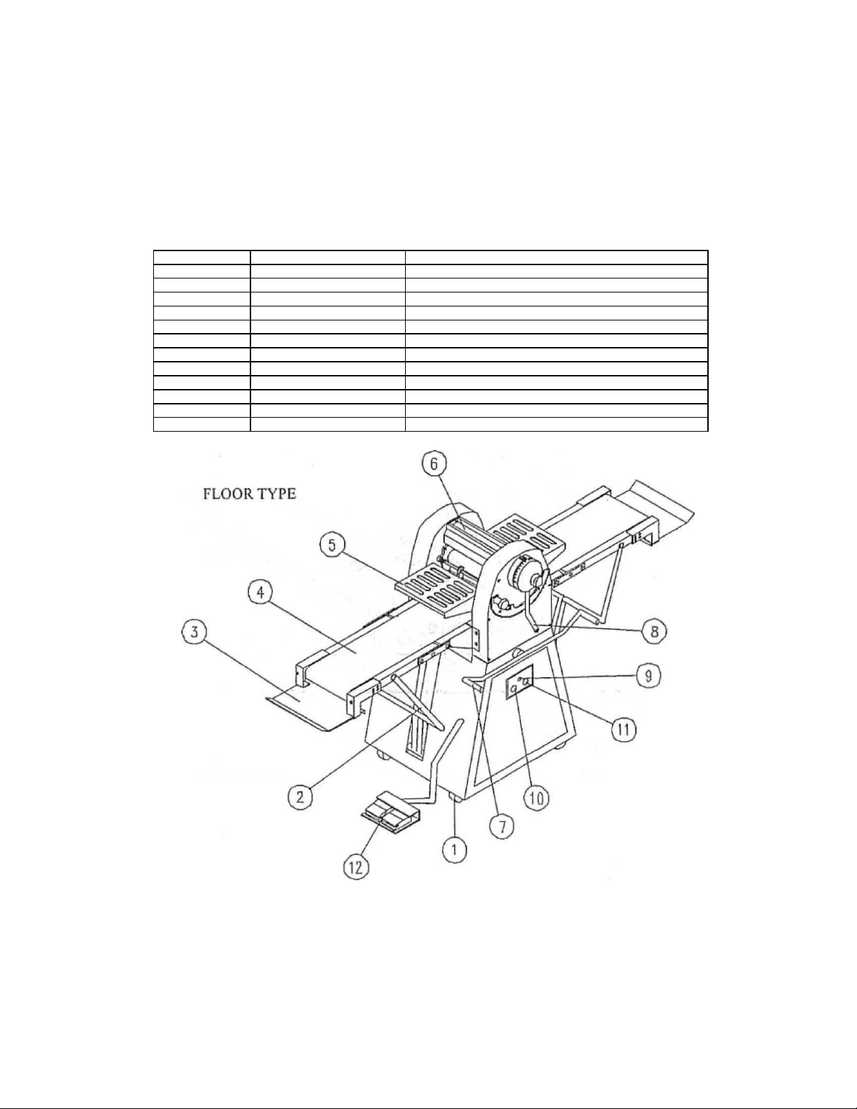
ITEM
NAME
PURPOSE
1
Wheel
Move seat
2
Table strut
Support the conveyor
3
Extension catch pan
For protecting outflow sheet dough from falling
4
Conveyor belt
Transmission dough
5
Safety guard
protect operator in operating
6
Roller head housing
Protect of the roller
7
Movement control lever
Lever for rolling forth or back by hand control
8
Handle
Adjust the gap between upper and lower rollers
9
Indicate light
Light when switch on
10
Power switch
Start-slop switch
11
Stop switch
Emergency stop
12
Reversible running board
Switch for rolling forth or back by foot control
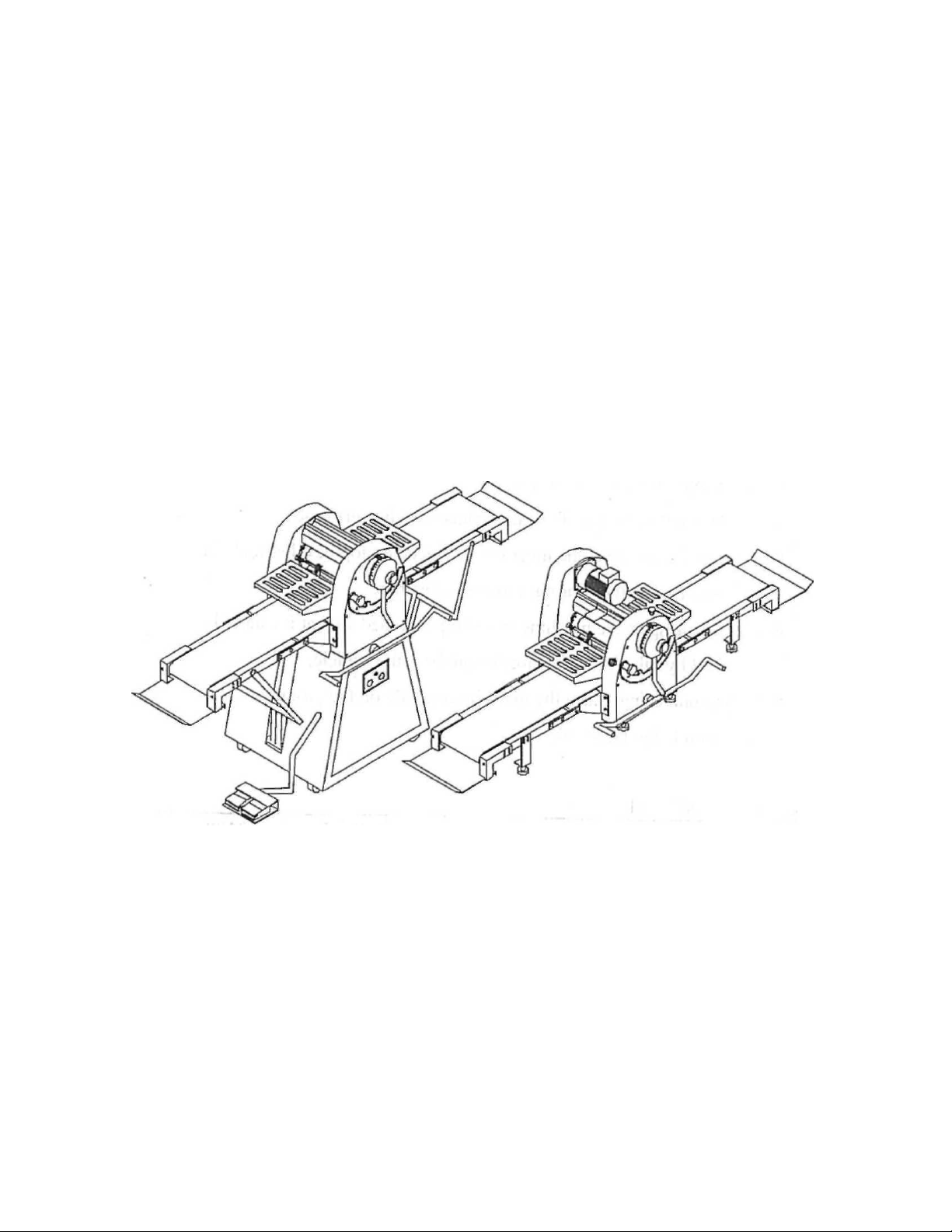
2. PARTS CHART OF MACHINE
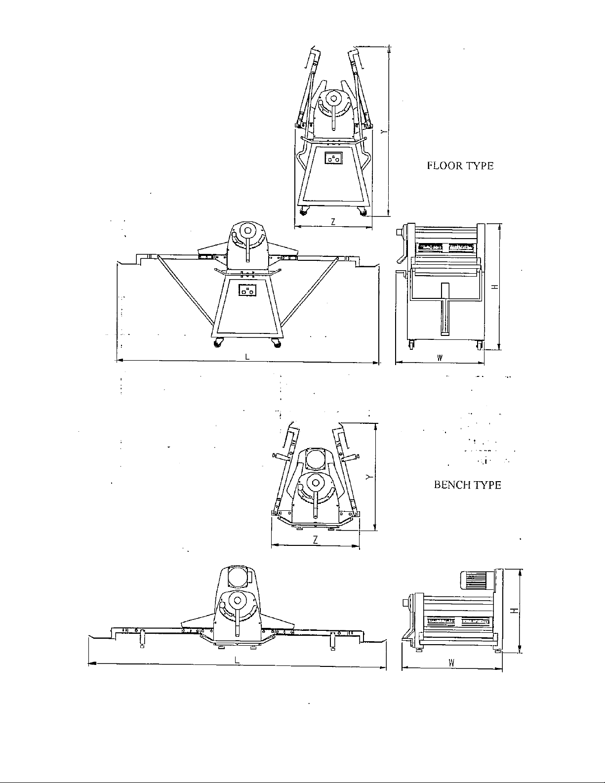
2-l.MAIN DIMENSION AND NAMES OF MACHINE
Page 7
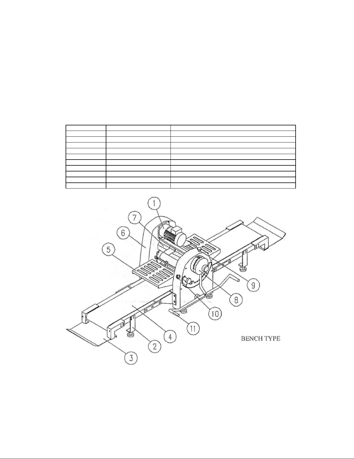
ITEM
NAME
PURPOSE
1
Motor
Reducer motor
2
Table frame
Support the conveyor
3
Extension catch pan
For protecting outflow sheet dough from falling
4
Conveyor belt
Transmission dough
5
Safety guard
protect operator in operating
6
Roller head housing
Protect of the roller
7
Movement control lever
Lever for rolling foith or back by hand control
8
Handle
Adjust the gap between upper and lower rollers
9
Stop switch
Emergency stop
10
Power switch
Start-stop switch
2. PAR CHART OF MACHINE
Page 8

MODEL
BMFRS03
BMFRS02
BMFRS01
BMCRS02
BMCRS01
TYPE
FLOOR TYPE
FLOOR TYPE
FLOOR TYPE
BENCH TYPE
BENCI-I TYPE
Belt width
(mm)
650
520
450
520
450
Motor power
(HP)
1 1 1
1/2
1/2
Voltage (V)
220/380
220/380
220/380
220/380
220/380
N.W./GW.
(kg)
216/286
176/216
156/192
124/150
118/140
Machine size
LxWxH(mm)
2500x1010x1220
2100x910x1120
2100x810x1120
2100x910x600
2100x810x600
Fold size
~xWxY(mm)
700x1010x1900
700x910x1630
700x810x1630
700x910x800
700x810x800
2-2. SPECIFICATIONS
8
Page 9
Page 10
3. MOUNTING OF MACHINE
3-1. HOW TO MOUNT THE MACHINE
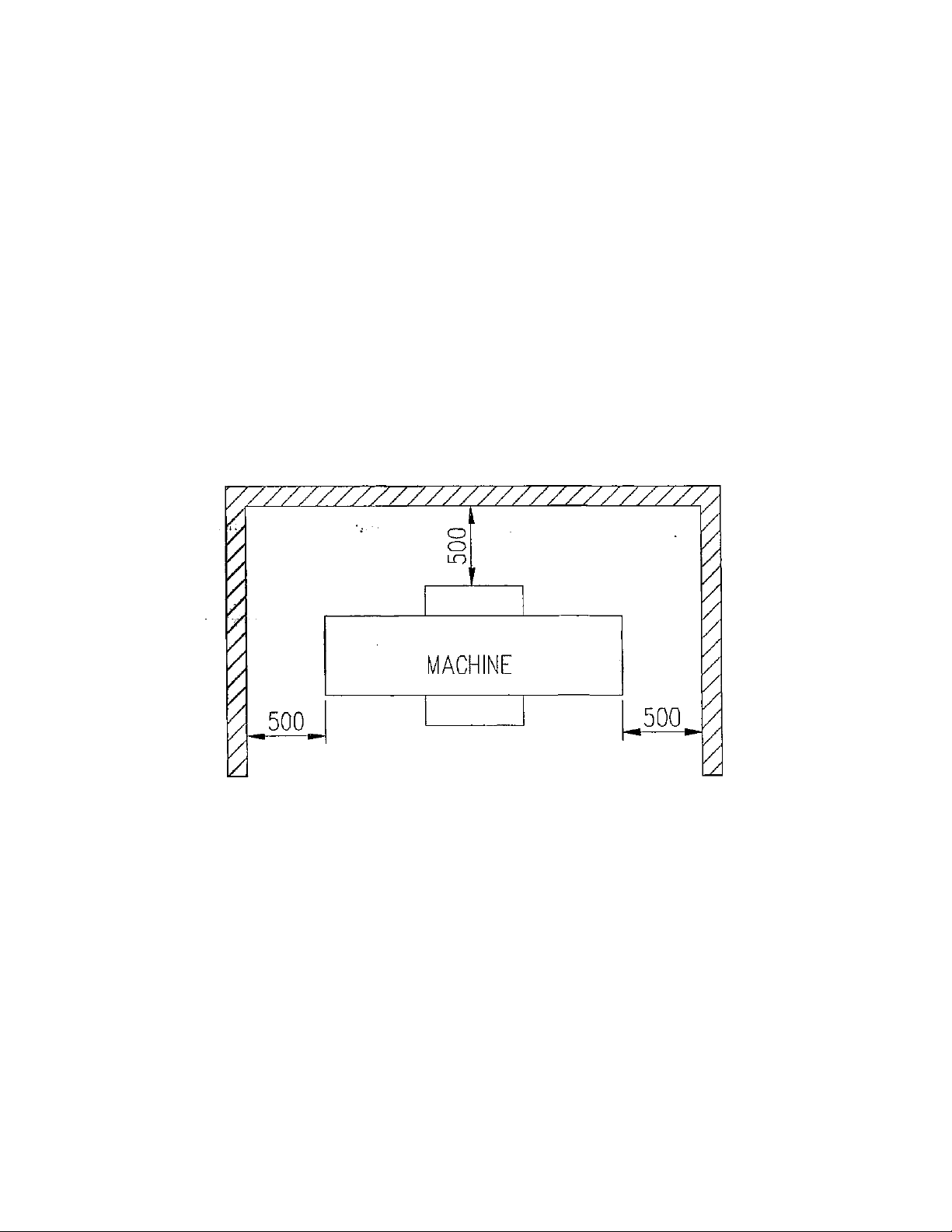
The machine must be installed on a horizontally-level floor. It should be pleased
in a location that is convenient for both operation and maintenance. The machine
safety features make it possible to stand close to the machine during operation.
Choose a suitable place for installing the machine, observing the minimum
distances from the walls as shown in the figure at the side. These spaces are
necessary for cleaning and routine maintenance operations and also ensure safe
operating conditions without the danger of dragging in and /or crushing.
The room must be provided with adequate lighting and ventilation.
Page 11

3-2.CONNECTING OF POWER SOURCE
* Qualified personnel in accordance with applicable codes and regulations
should make electrical connections.
*The machine is provided with one single electrical connection with connection
cable at the rear.
* Check that the rating plate voltage corresponds to the mains voltage.
* The machine must be connected to a manual control voltage disconnection
device fitted in an easily accessible position so that the machine electrical
equipment can be separated from the mains when necessary.
* In particular, the system must be installed by a technically and professionally
qualified electrician listed in the appropriate register. The installer is obliged to
provide the customer with a declaration of conformity. Old systems should be
checked in order to adapt them to the latest safety regulations and
state-of-the-art.
Page 12

4.OPERATION OF THE MACHINE
4-1. General operation
1. Put an appropriate amount of dough on the conveyor and press dough flatly by
hand.
2. By operating handle to adjust the gap between upper roller an lower roller as
large as possible according to dough measure. Then during the following
rolling process gradually adjust the gap smaller and smaller, until sheet dough
reaches the desired thickness. In the beginning, repeat spraying oil, folding,
and rolling for a few times, until sheet oil and sheet dough are evenly folded in
layers.
3. Turn on the electric power.
4. The conveyor belts convey the dough to be rolled through the calibration
cylinders from right to left and vice versa. This right-left direction variation is
determined by the control lever as follow: When the lever is turned to the left,
movement is from right to left whereas if it is turned to the right, movement
will be from left to right.
* You can operate reversibly Running by FOOT CONTROL SWITCH in floor
type.
5. Finish work.
Page 13
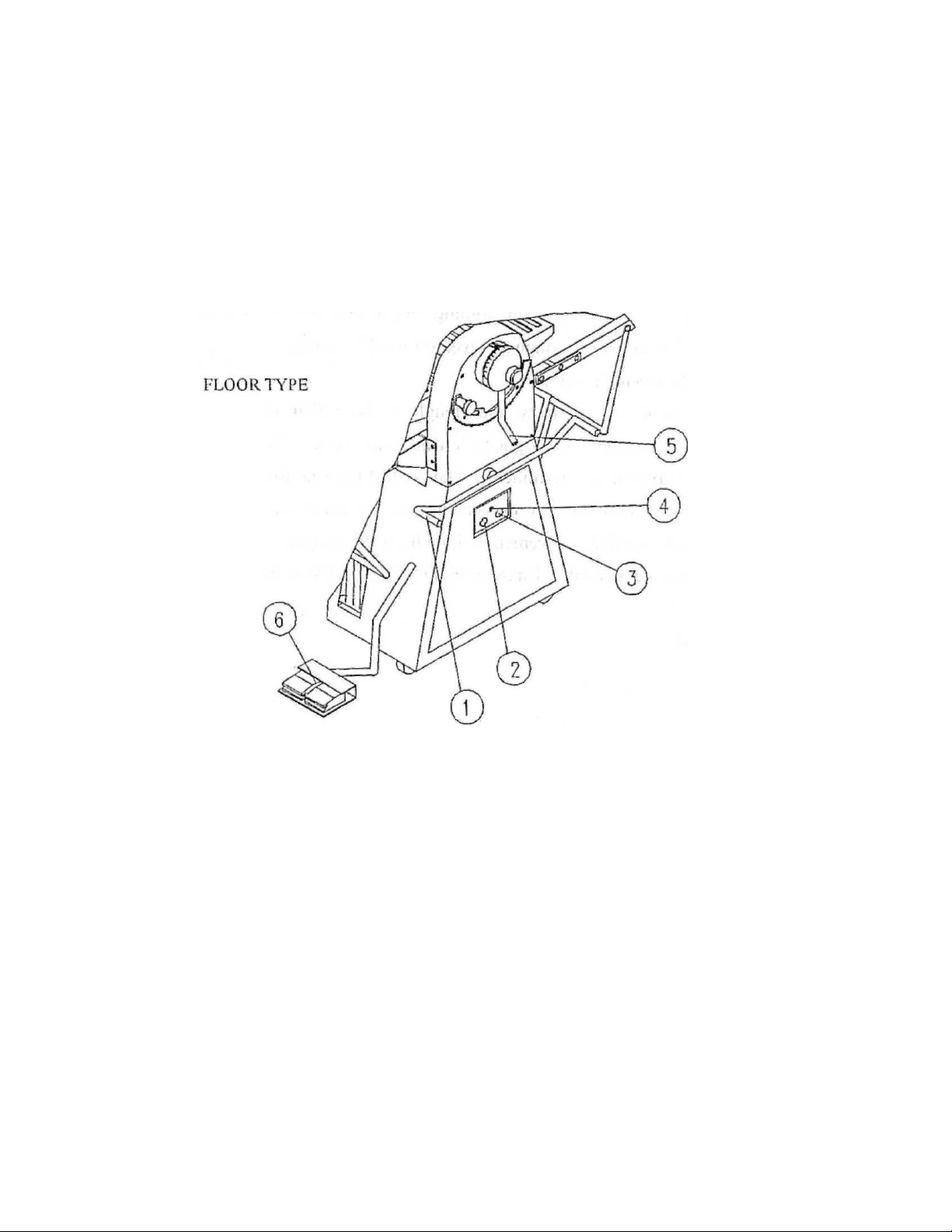
4-2-1. CONTROLS OF FLOOR TYPE
1.Movement control lever... ever for rolling forth or back by hand control
2. Power switch ................... .Start-stop switch
3. Stop switch ....................... Emergency stop
4. Indicate light ..................... Light when switch on
5. Handle ........................ Adjust die gap between upper and lower rollers
6. Reversible miming board-• •-Switch for rolling forth or back by foot control
Page 14
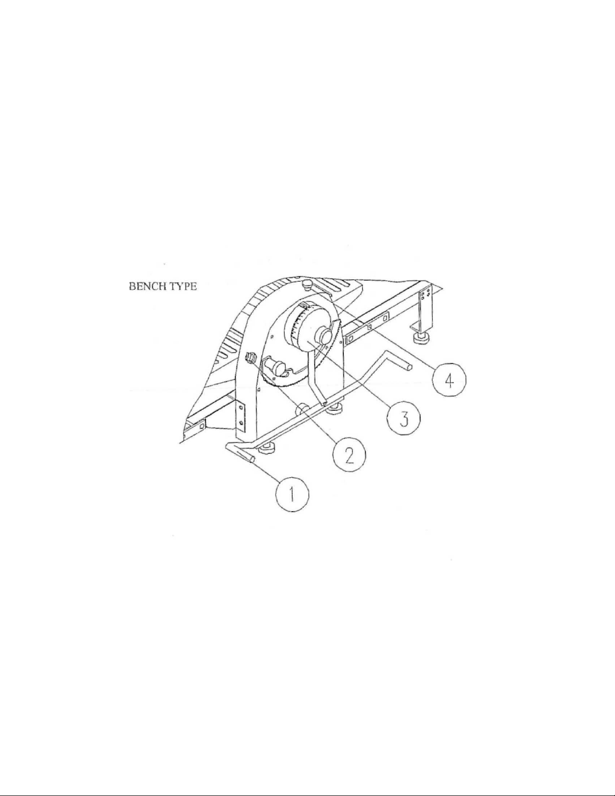
4-2-2.CONTROLS OF BENCFI TYPE
1.Movement control lever...ever for rolling forth or back by hand control
2. Power switch ..................... Start-stop switch
3. Handle ........................ Adjust the gap between upper and lower rollers
4. Stop switch ....................... .Emergency stop
4-3. CLEANING
WARNING-UNPLUG MACHINE BEFORE CLEANING OR SERVICING
* Alter each day's use , clean the conveyor, flour pan and surface thoroughly with
hot water and a mild soap solution and rinse with either a mild soda or vinegar
solution. Rinse thoroughly with a clean damp cloth.
- f Clean under machine occasionally.
Page 15
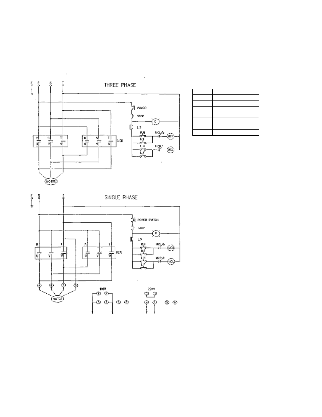
5.CIRCUIT DIAGRAM
LS
LIMIT SWITCH OF GUARD
R.H
RIGHT HAND
R.F
RIGHT FOOT
LH
LEFT HAND
L.F
LEFT FOOT
MCR
RIGHT MICRO SWITCH
MCL
LEFT MICRO SWITCH
MOTOR
MOTOR
5-1. CIRCUIT DIAGRAM
Page 16

NO.
MAME
NO.
MAME
1
key 2 Shaft sprocket
3
Deep groove ball bearing 600-1ZZ
4
Bearing block
5
Shaft sprocket
6
Chain
7
Chain
8
Pin bearing FC-20
9
Deep groove ball bearing 6U03ZZ
10
C. Retainer ring S-17
11
Stay
12
Chain
13
Shaft sprocket
14
Chain
15
Chain
16
Spacers
17
Washer, Oat
18
Bolt
19
Support bracket
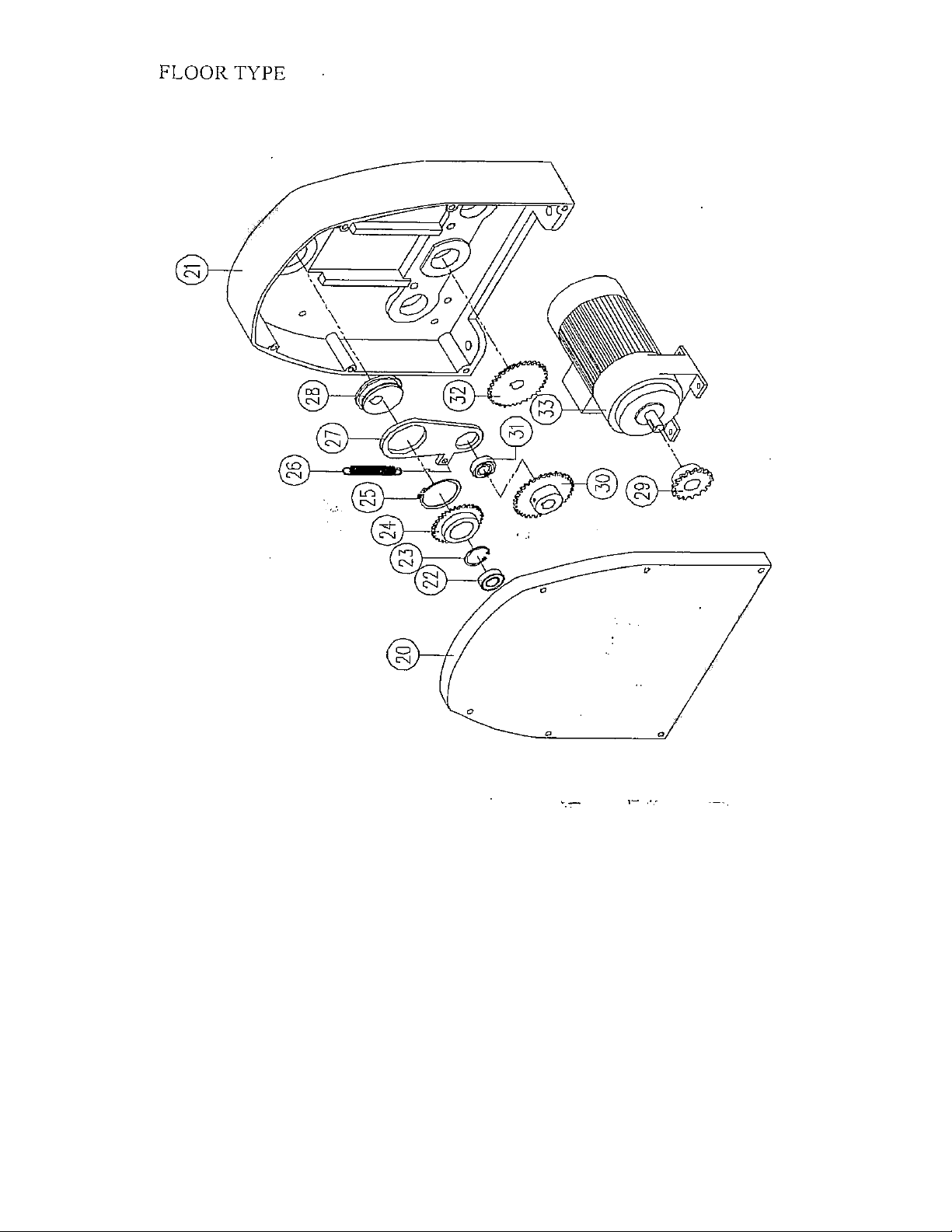
20
Rear panel
21
Rear casing
22
Deep groove ball bearing 6205ZZ
23
C. Retainer ring R-52
24
Chain
25
C. Retainer ring S-70
26
Expansion spring
27
Connecting board
28
Lever ring
29
Chain
30
Chain
31
Deep groove ball bearing 6205ZZ
32
Chain
33
Motor
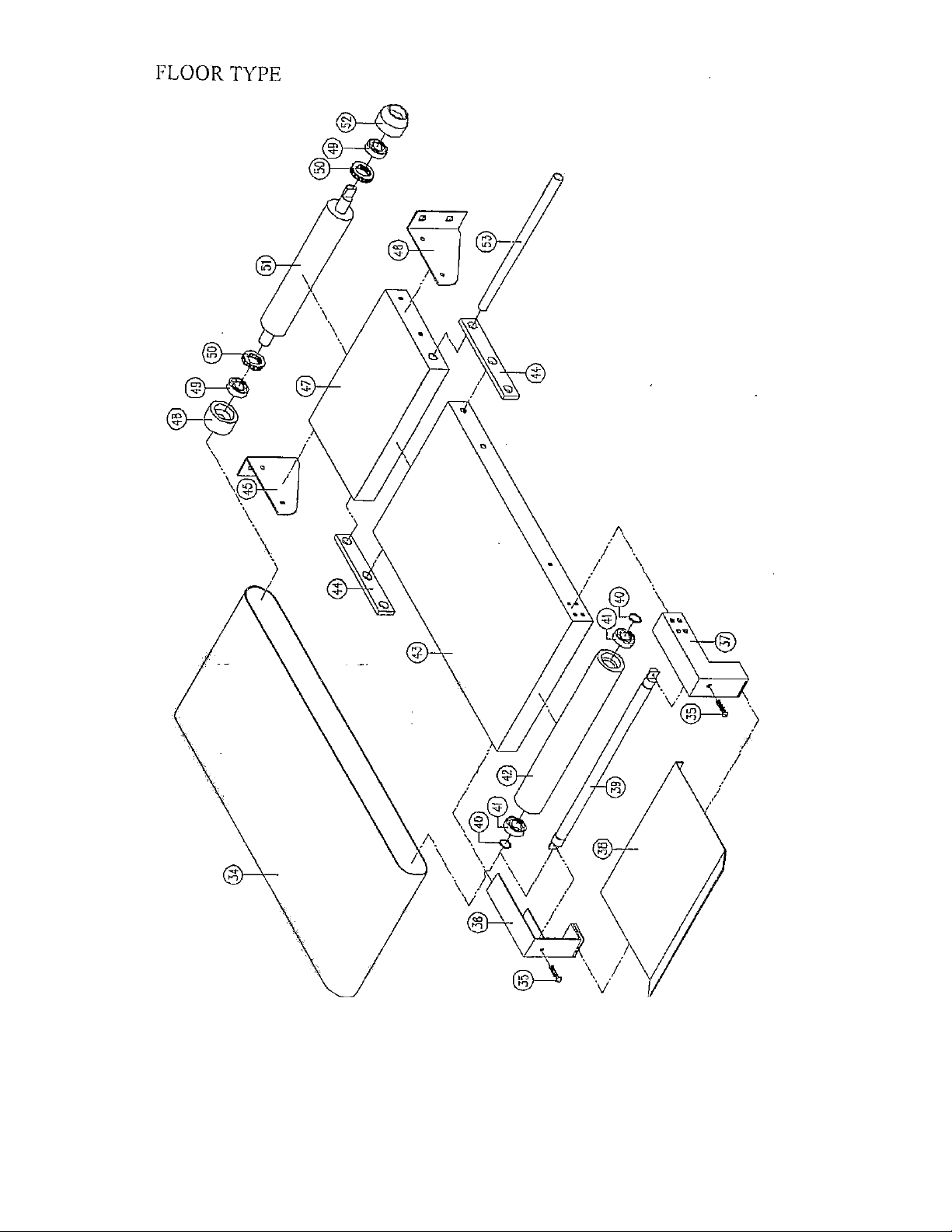
34
Conveyor belt
35
Bolt, adjustable
36
Left support braeket
37
Right support bracket
38
Extension catch pan
NO.
MAME
NO.
MAME
39
Shaft, driven
40
C. Retainer ring S-17
41
Deep groove ball bearing 6203ZZ
42
Roller
43
Rase
44
Connecting rod
45
Left support bracket
46
Right support bracket
47
Base
48
Bearing block
49
Deep groove ball bearing 6003ZZ
50
Thrust ball bearing 51203
51
Shall, roll
52
Bearing block
53
Axle, supporting
54
Nut
55
Seat, sliding
56
Deep groove ball bearing 6205ZZ
57
Up roller
58
Bolt, adjustable
59
Lever, dead
60
Link mass
61
Torsional spring
62
Bar, fulcrum
63
Strickle sweep
64
Bar, fulcrum
65
Front casing
66
Roller head housing
67
Stop pin
68
Safety guard
69
Deep groove ball bearing 6205ZZ
70
Down roller
71
Strickle sweep
72
Bolt, support
73
Bolt, anchor block
74
Set screw
75
Expansion spring
76
Rings
77
Trigger
78
Microswitch
79
Bolt, hexagon head
80
Washer, spring
NO.
MAME
NO.
MAME
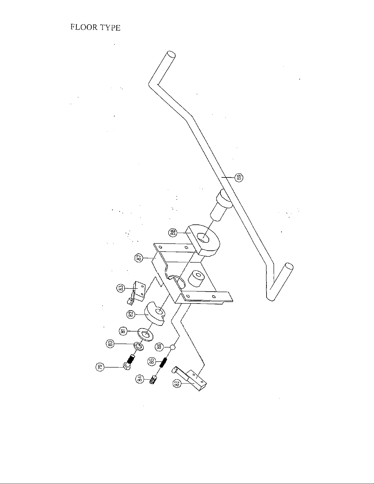
81
Washer, flat
82
Trigger
83
Microswitch
84
Bolt
85
Compression spring
86
Ball
87
Fixed support
88
Locating mass
89
Movement control lever
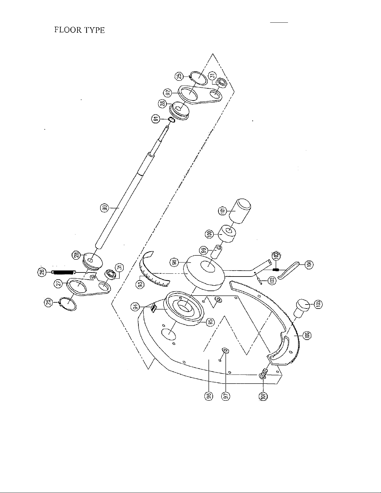
90
Bolt, shaft
91
C. Retainer ring S-25
92
Connecting board
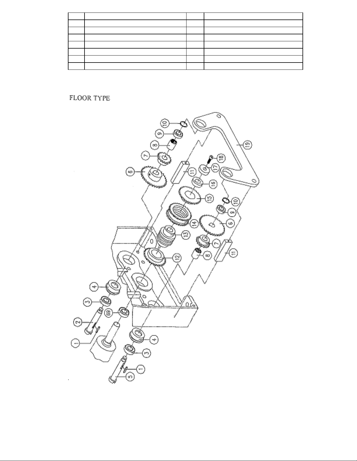
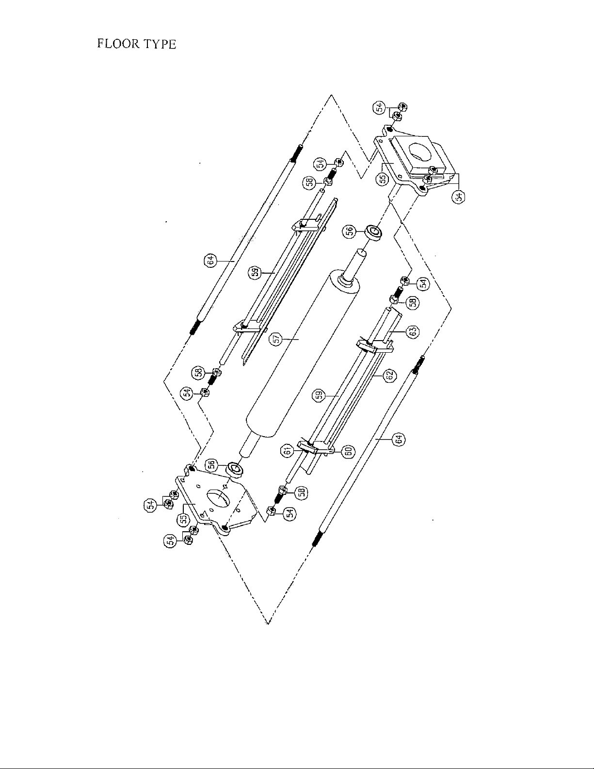
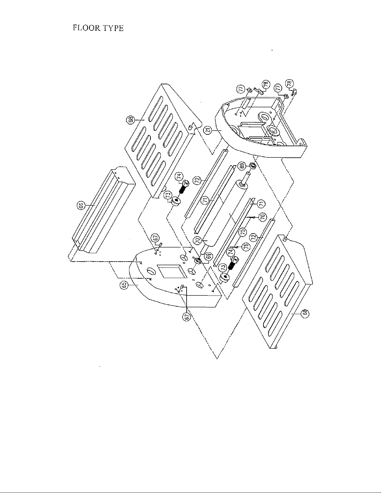
6.PARTS CATALOG
6-1 PARTS CATALOG
FLOOR TYPE
Page 17
93
Graduated scale
94
Finger
95
Handle base
96
Front panel
97
Washer, flat
98
Handle
99
Spacers
100
Spacers
101
Bolt cover
102
Fin
103
Compression spring
104
Trigger, locking pin
105
Locking mass
106
Rail rest
107
Bolt, cheese head
108
Page 18
Page 19
Page 20
Page 21
Page 22
Page 23
Page 24

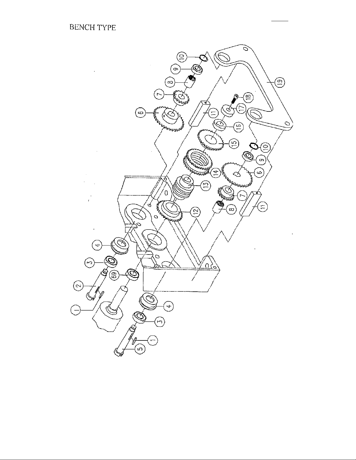
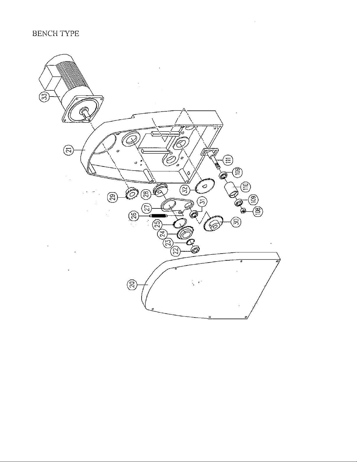
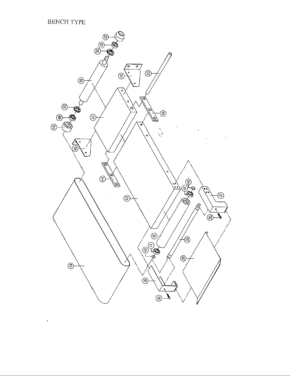
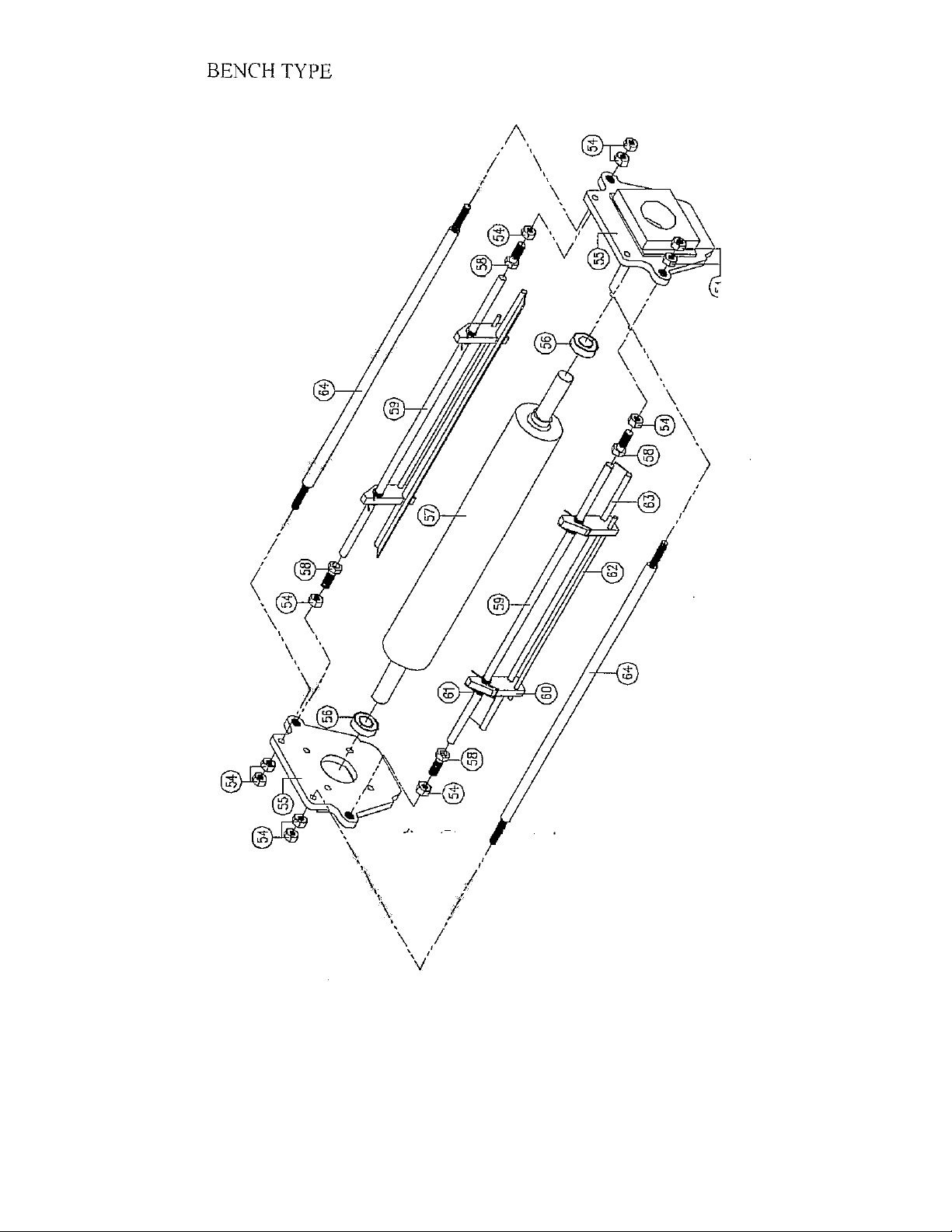
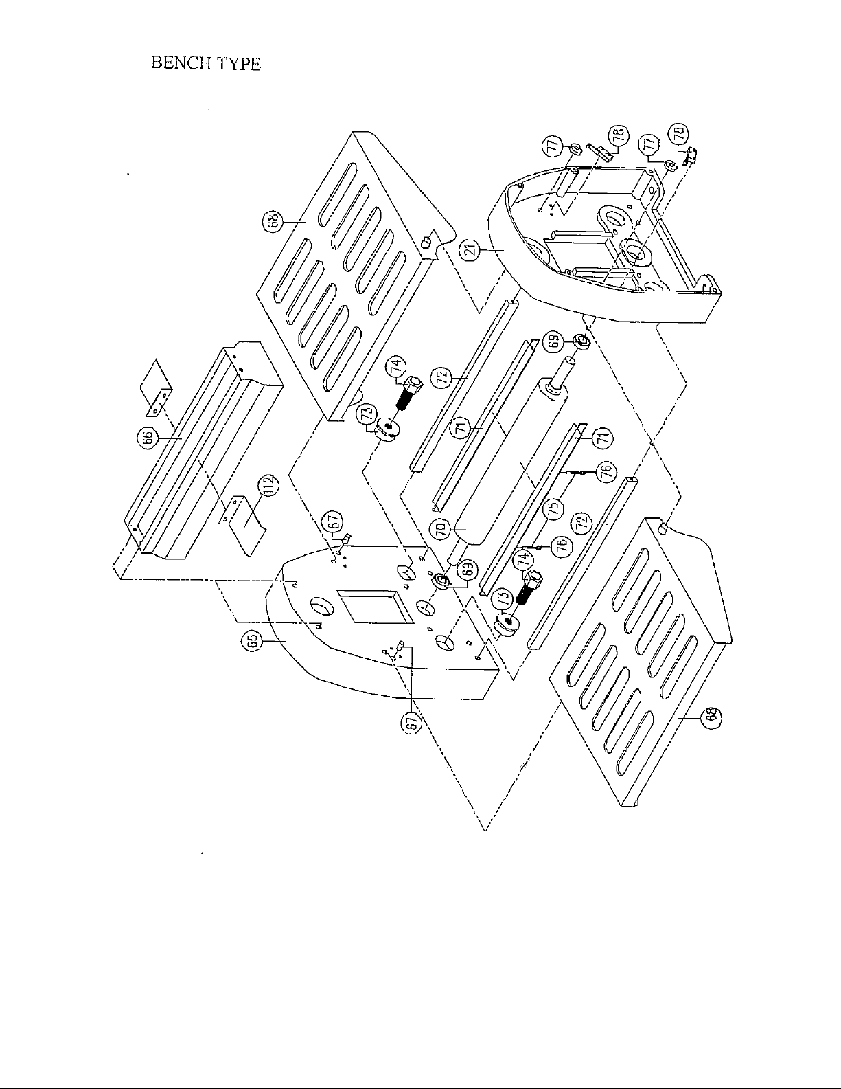
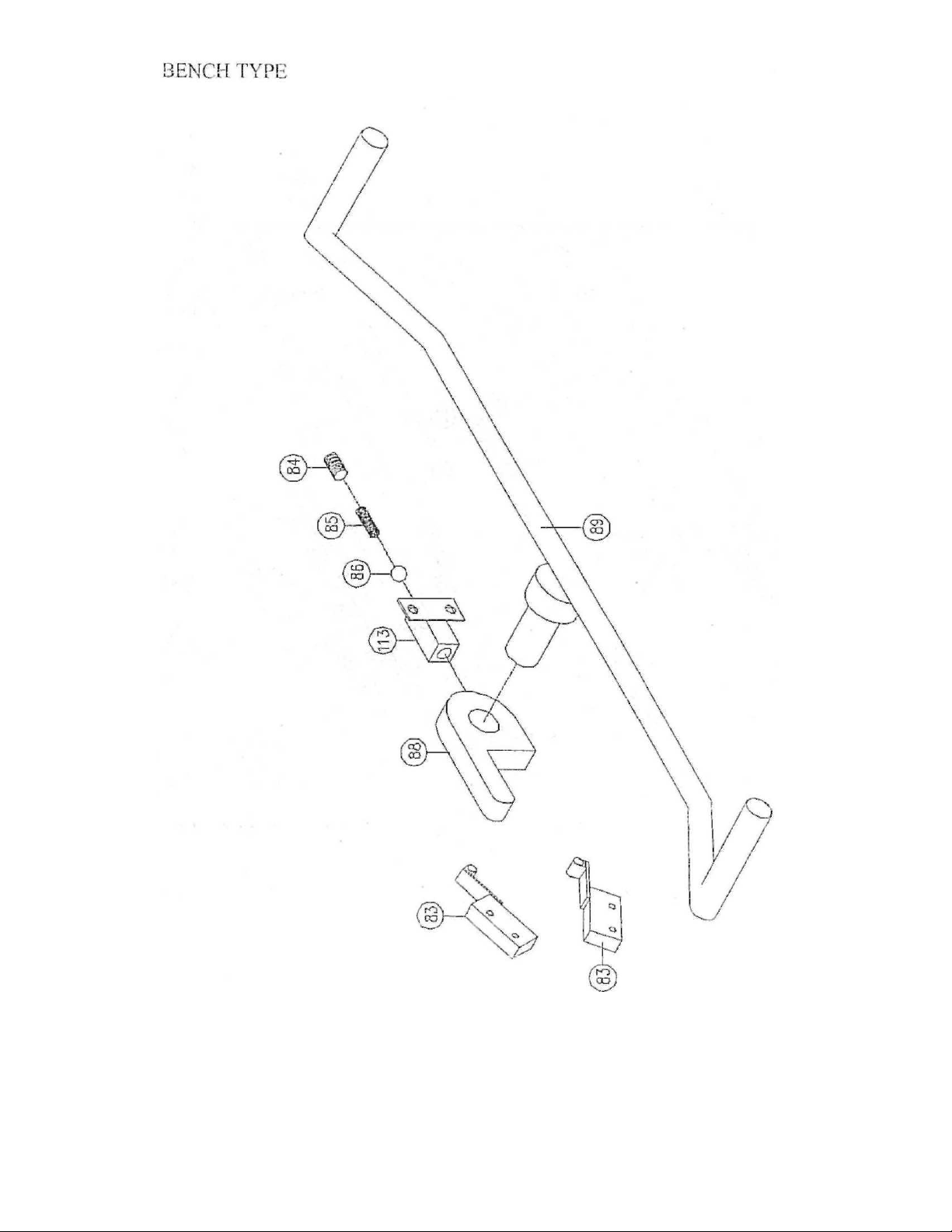
BENCH TYPE
NO.
MAME
NO.
MAME
1
key 2 Shaft sprocket
3
Deep groove ball bearing 6004ZZ
4
Bearing block
5
Shaft sprocket
6
Cham
7
Chain
8
Pin bearing FC-20
9
Deep groove ball bearing 6003ZZ
10
C. Retainer ring S-17
11
Stay
12
Chain
13
Shaft sprocket
14
Chain
15
Chain
16
Spacers
17
Washer, flat
18
Bolt
19
Support bracket
20
Rear panel
21
Rear casing
22
Deep groove ball bearing 6205ZZ
23
C. Retainer ring R-52
24
Chain
25
C. Retainer ring S-70
26
Expansion spring
27
Connecting board
28
Lever ring
29
Chain
30
Chain
31
Deep groove ball bearing 6205ZZ
32
Chain
33
Motor
34
Conveyor belt
35
Bolt, adjustable
36
Left support bracket
37
Right support bracket
38
Extension catch pan
NO.
MAME
NO.
MAME
39
Shalt, driven
40
C. Retainer ring S-17
41
Deep groove ball bearing 6203ZZ
42
Roller
43
Base
44
Connecting rod
45
Left support bracket
46
Right support bracket
47
Base
48
Bearing block
49
Deep groove ball bearing 6003ZZ
50
Thrust ball bearing 51203
51
Shaft, roll
52
Bearing block
53
Axle, supporting
54
Nut
55
Seat, sliding
56
Deep groove ball bearing 6205ZZ
57
Up roller
58
Bolt, adjustable
59
Lever, dead
60
Link mass
61
Torsional spring
62
Bar, fulcrum
63
Strickle sweep
64
Bar, fulcrum
65
Front casing
66
Roller head housing
67
Stop pin
68
Safety guard
69
Deep groove ball bearing 6205ZZ
70
Down roller
71
Strickle sweep
72
Bolt, support
73
Bolt, anchor block
74
Set screw
75
Expansion spring
76
Rings
77
Trigger
78
Microswitch
79
--------------
80
—- -
83
Microswitch
84
Boll
85
Compression spring
86
Ball
87
- —
88
Locating mass
89
Movement eontrol lever
90
Boll, shaft
91
C. Retainer ring S-25
92
Connecting board
93
Graduated scale
94
Finger
95
Handle base
96
Front panel
97
Washer, (lal
98
Handle
99
Spacers
100
Spacers
101
Bolt cover
102
Pin
103
Compression spring
104
Trigger, locking pin
105
Locking mass
106
Rail rest
107
Bolt, cheese head
108
Nut
109
Deep groove ball bearing 6003ZZ
110
Idler wheel
111
Fixed base
112
Fixed board
113
Locating mass
114
Page 25
Page 26
Page 27
Page 28
Page 29
Page 30
Page 31
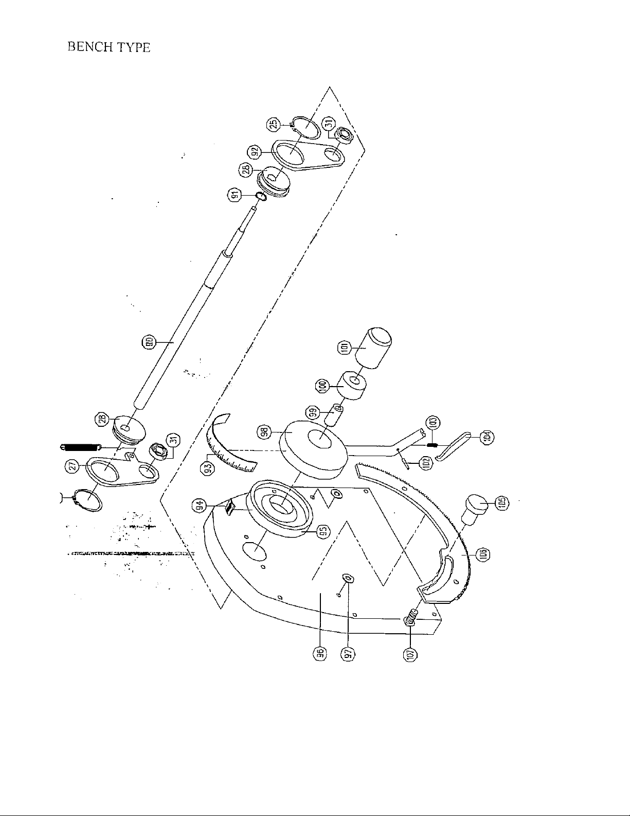
Page 32
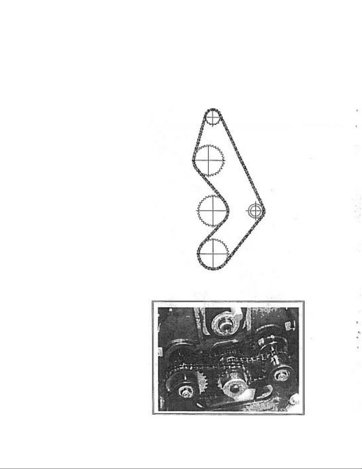
6-2.CHAIN ALLOCATION PLAN
BENCH TYPE
Front
TOP: Rear Chain Allocation
BOTTOM: Front Chain Allocation
Page 33
 Loading...