

Page 1
INSTALLATION AND OPERATION MANUAL
ELECTRIC GRIDDLE
EP514
EP516
EP518
For use in GB & IE
229351-6
Page 2

MANUFACTURED BY
Moffat Limited
PO Box 10001
Christchurch
New Zealand
Ph: (03) 389 1007
Fax: (03) 389 1276
WORLD-WIDE BRANCHES
UNITED KINGDOM
Blue Seal
67 Gravelly Business Park
Gravelly Park
Birmingham
West Midlands
B24 8TQ
Ph: (121) 327 5575
Fax: (121) 327 9711
UNITED STATES
Moffat Inc
3765 Champion Blvd
Winston-Salem
North Carolina 27115
Ph: (336) 661 0257
Fax: (336) 661 9546
CANADA
Serve Canada
22 Ashwarren Road
Downview
Ontario M3J1Z5
Toll Free:800 263 1455
Ph: (416) 631 0601
Fax: (416) 631 0315
[email protected]
www.servecanada.com
www.moffat.com
NEW ZEALAND
Christchurch
Moffat Limited Moffat Limited
PO Box 10-001 4 Waipuna Road
16 Osborne Street Mt Wellington
Christchurch Auckland
Ph: (03) 389 1007 Ph: (09) 574 3150
Fax: (03) 389 1276 Fax: (09) 574 3159
AUSTRALIA
Victoria
Moffat Pty Limited Moffat Pty Limited
740 Springvale Road 3/142 James Ruse Drive, Rose Hill
Mulgrave, Melbourne PO Box 913, Smithfield
Victoria 3171 Sydney, N.S.W. 2142
Ph: (03) 9518 3888 Ph: (02) 8833 4111
Fax: (03) 9518 3838 Fax: (02) 8833 4133
Western Australia
Moffat Pty Limited Moffat Pty Limited
67 Howe Street 30 Prosperity Place
Osbourne Park Geebung, Brisbane
WA 6017 Queensland 4034
Ph: (08) 9202 6820 Ph: (07) 3630 8600
Fax: (08) 9202 6836 Fax (07) 3630 8623
Auckland
New South Wales
Queensland
The reproduction or copying of any part of this manual by any means whatsoever is strictly forbidden unless authorized previously in
writing by the manufacturer.
In line with policy to continually develop and improve its products, Moffat Ltd. reserves the right to change the specifications and
design without prior notice.
© Copyright Moffat Ltd. February 2008.
Page 3

Blue Seal Electric Griddle
Contents
EP514 Electric Griddle, 600mm.
EP516 Electric Griddle, 900mm.
EP518 Electric Griddle, 1200mm.
Introduction ............................................................................................. 2
Specifications ........................................................................................... 3
Model Numbers Covered in this Specification
General
Electrical Supply Requirements
Electrical Connection
Dimensions
Installation ................................................................................................ 9
Installation Requirements
Unpacking
Location
Clearances
Assembly
Electrical Connection
Commissioning
Operation................................................................................................. 12
Operation Guide
Description of Controls
Griddle Operation
Cleaning and Maintenance ...................................................................... 13
General
After Each Use
Daily Cleaning
Weekly Cleaning
Periodic Maintenance
Fault Finding............................................................................................ 16
Circuit Schematics ................................................................................... 17
Replacement Parts List ........................................................................... 20
Page 4
Introduction
We are confident that you will be delighted with your BLUE SEAL ELECTRIC GRIDDLE, and it will become a
most valued appliance in your commercial kitchen.
To ensure you receive the utmost benefit from your new BLUE SEAL Appliance, there are two important
things you can do.
Firstly:
Please read the instruction book carefully and follow the directions given. The time taken will be well
spent.
Secondly:
If you are unsure of any aspect of the installation, instructions or performance of your appliance,
contact your BLUE SEAL dealer promptly. In many cases a phone call could answer your question.
CE Only:
These instructions are only valid if the country code appears on the appliance. If the code does not
appear on the appliance, refer to the supplier of this appliance to obtain the technical instructions for
adapting the appliance to the conditions for use in that country.
WARNING:
MPROPER INSTALLATION, ADJUSTMENT, ALTERATION, SERVICE OR MAINTENANCE CAN CAUSE PROPERTY
I
DAMAGE, INJURY OR DEATH. READ THE INSTALLATION, OPERATING AND MAINTENANCE INSTRUCTIONS
THOROUGHLY BEFORE INSTALLING OR SERVICING THIS APPLIANCE.
WARNING:
REAT CARE MUST BE TAKEN BY THE OPERATOR TO USE THE EQUIPMENT SAFELY TO GUARD IT AGAINST RISK
G
OF FIRE.
• T
• I
• DO NOT
•
HE APPLIANCE MUST NOT BE LEFT ON UNATTENDED.
T IS RECOMMENDED THAT A REGULAR INSPECTION IS MADE BY A COMPETENT SERVICEMAN TO ENSURE
CORRECT AND SAFE OPERATION OF YOUR APPLIANCE IS MAINTAINED.
STORE OR USE GASOLINE OR OTHER FLAMMABLE VAPOURS OR LIQUIDS IN THE VICINITY OF
THIS OR ANY OTHER APPLIANCE.
DO NOT SPRAY AEROSOLS IN THE VICINITY OF THIS APPLIANCE WHILE IT IS IN OPERATION.
C
AUTION
:
This appliance is;
•
For professional use and is only to be used by suitably qualified / trained
persons.
•
Only qualified service persons are to carry out installation, servicing and
gas conversion operations.
•
Components having adjustments protected (e.g. paint sealed) by the
manufacturer should not be adjusted by the user / operator.
•
DO NOT operate the appliance without the legs supplied fitted.
2
Page 5

Specifications
Model Numbers Covered in this Specification
EP514 - B Electric Griddle 600mm wide Bench Model.
EP514 - CB Electric Griddle 600mm wide with Cabinet Base.
EP514 - LS Electric Griddle 600mm wide on Leg Stand.
EP516 - B Electric Griddle 900mm wide Bench Model.
EP516 - CB Electric Griddle 900mm wide with Cabinet Base.
EP516 - LS Electric Griddle 900mm wide on Leg Stand.
EP516 - RB Electric Griddle 900mm wide with Refrigerated Base.
EP518 - B Electric Griddle 1200mm wide Bench Model.
EP518 - CB Electric Griddle 1200mm wide with Cabinet Base.
EP518 - LS Electric Griddle 1200mm wide on Leg Stand.
EP518 - RB Electric Griddle 1200mm wide with Refrigerated Base.
General
A commercial heavy duty, fully modular, electric griddle using stainless steel sheathed heating
elements with dual thermostatic control zones.
Using a 20mm thick griddle plate with the option of either ribbed or chromed mirror plate options.
The Griddle is constructed as a hob unit and is available in 4 options, on Leg Stand (-LS), Bench
Mount (-B), Cabinet Base (-CB) or with Refrigerated Base (RB) models (Not available for EP514
Models).
3
Page 6
Specifications
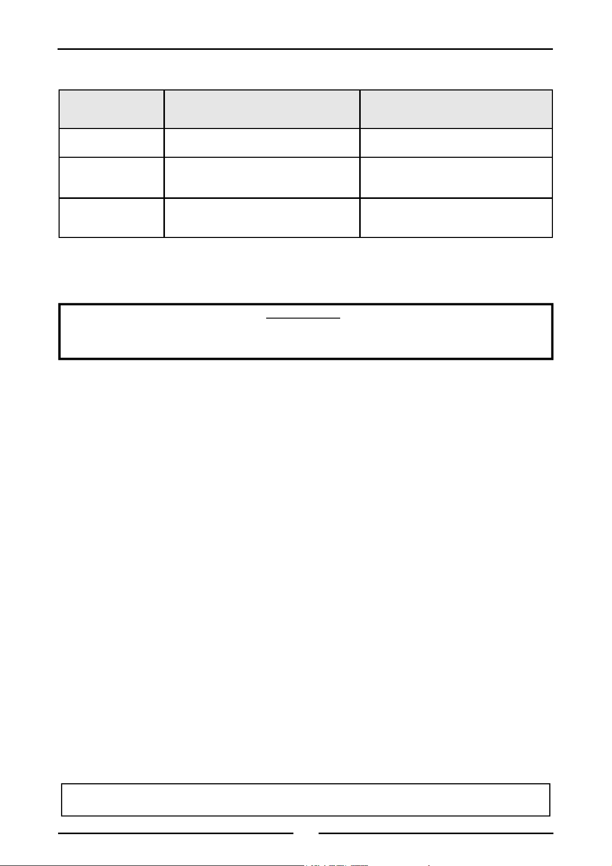
Electrical Supply Requirements
MODEL
EP514
1-Phase Connection
1P+N+E
230-240V, 50 / 60Hz
7.2 kW
30 Amps @ 240 V
3-Phase Connection
3P+N+E
400-415V, 50 / 60Hz
---------
L1 - 16.4 Amps
EP516 --------- 12.0 kW
L2 - 16.4 Amps
L3 - 16.4 Amps
L1 - 24.5 Amps
EP518 --------- 18.0 kW
L2 - 24.5 Amps
L3 - 24.5 Amps
Electrical Connection
WARNING:
HIS APPLIANCE MUST BE EARTHED. IF THE SUPPLY CORD IS DAMAGED, IT MUST BE REPLACED BY A SUITABLY
T
QUALIFIED PERSON IN ORDER TO AVOID A HAZARD.
Bench Models Only
Electrical supply connection point is located at the rear of the appliance, approximately 130mm from
the right hand side and 32mm from the rear and 85mm from the floor.
Cabinet Base, Leg Stand and Refrigeration Bases
Electrical supply connection point is located at the rear of the appliance, approximately 130mm from
the right hand side and 32mm from the rear and 740mm from the floor.
When connecting a Blue Seal electric appliance to the main supply, ensure that the following is
carried out:-
• An isolating switch is fitted within 2m of the appliance, but not on the appliance and in
such a position that the user does not have to reach across the cooking surface.
• Supply cord shall be oil-resistant, sheathed flexible cable and not lighter than ordinary
polychloroprene or other equivalent synthetic elastomer sheathed cord (as per AS / NZS
3191 part 2.10.11. or IEC 60245-IEC-57) e.g. H05 RN-F Type.
• The branch supply line shall be individually overload protected to the correct current rating
and the supply chord shall be protected against any mechanical or thermal damage.
• A grommet is fitted around the wiring entry hole into the appliance.
• All wiring connections must be tight.
Refer to the appropriate wiring standards for the size of cable that is to be supplied to an appliance
for the current drawn on that line.
For the Refrigeration Cabinet Specifications refer to the Refrigeration Cabinet Installation and
Operation Manual supplied with the appliance.
4
Page 7
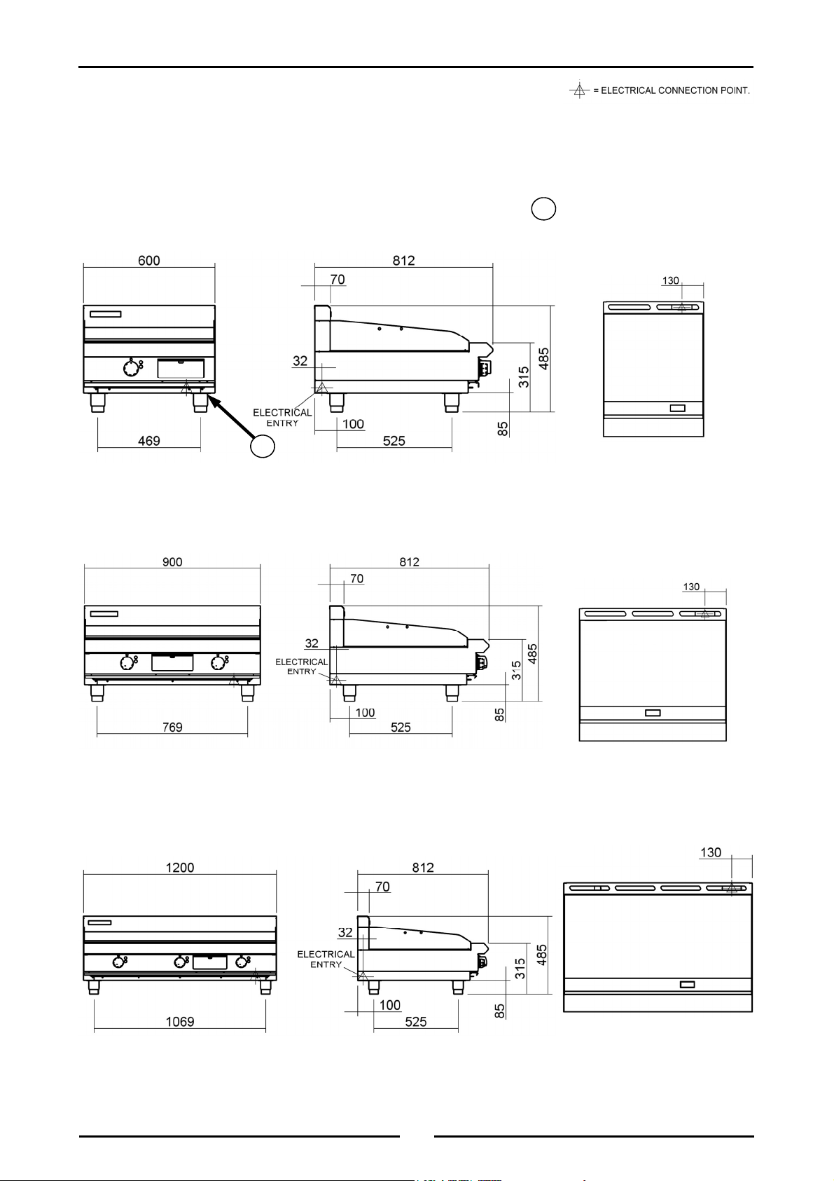
Dimensions for Bench Models
EP514 - B
R
Dimensions
= Rating Plate Location for
R
this option.
EP516 - B
EP518 - B
5
Page 8
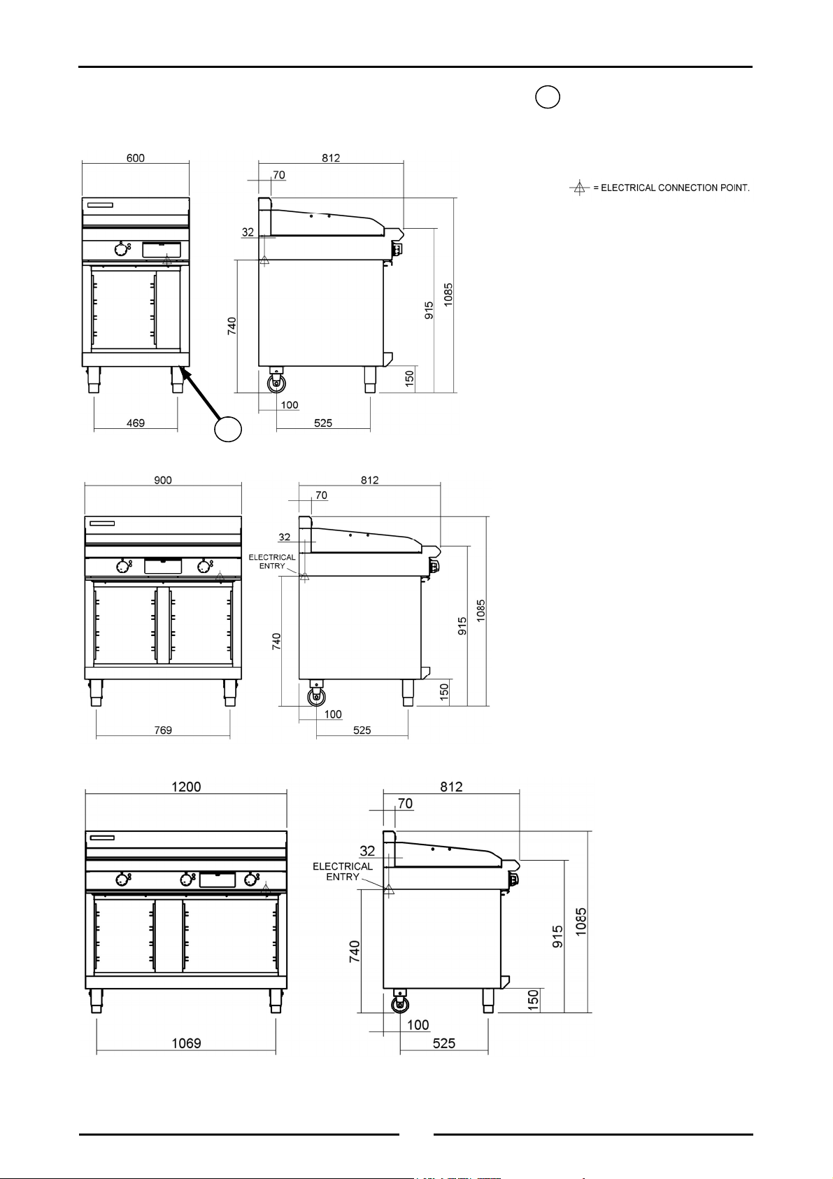
Dimensions
Dimensions for Cabinet Base Models
EP514 - CB
R
EP516 - CB
= Rating Plate Location for
R
this option.
EP518 - CB
6
Page 9
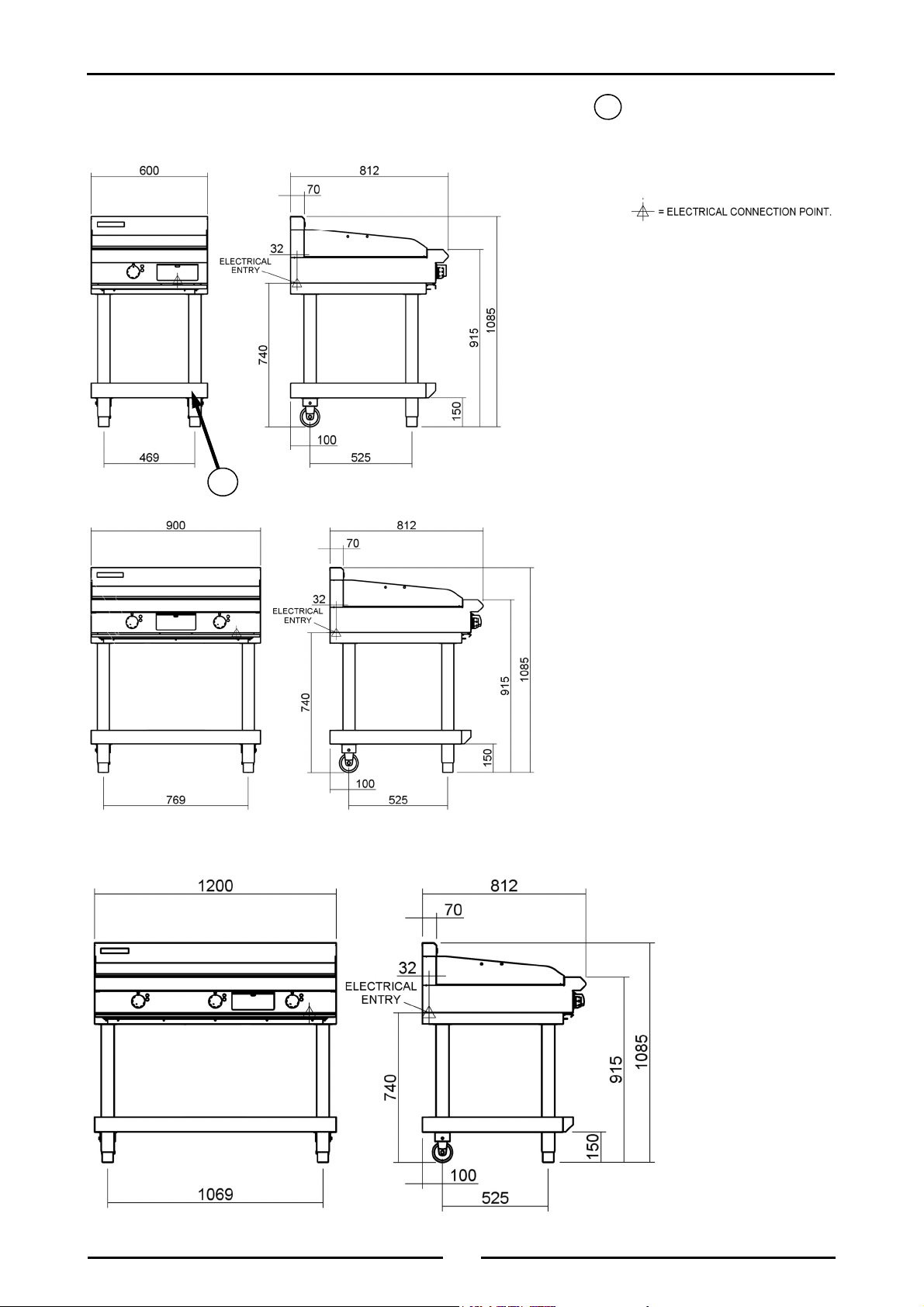
Dimensions
Dimensions for Leg Stand Models
EP514 - LS
R
EP516 - LS
= Rating Plate Location for
R
this option.
EP518 - LS
7
Page 10
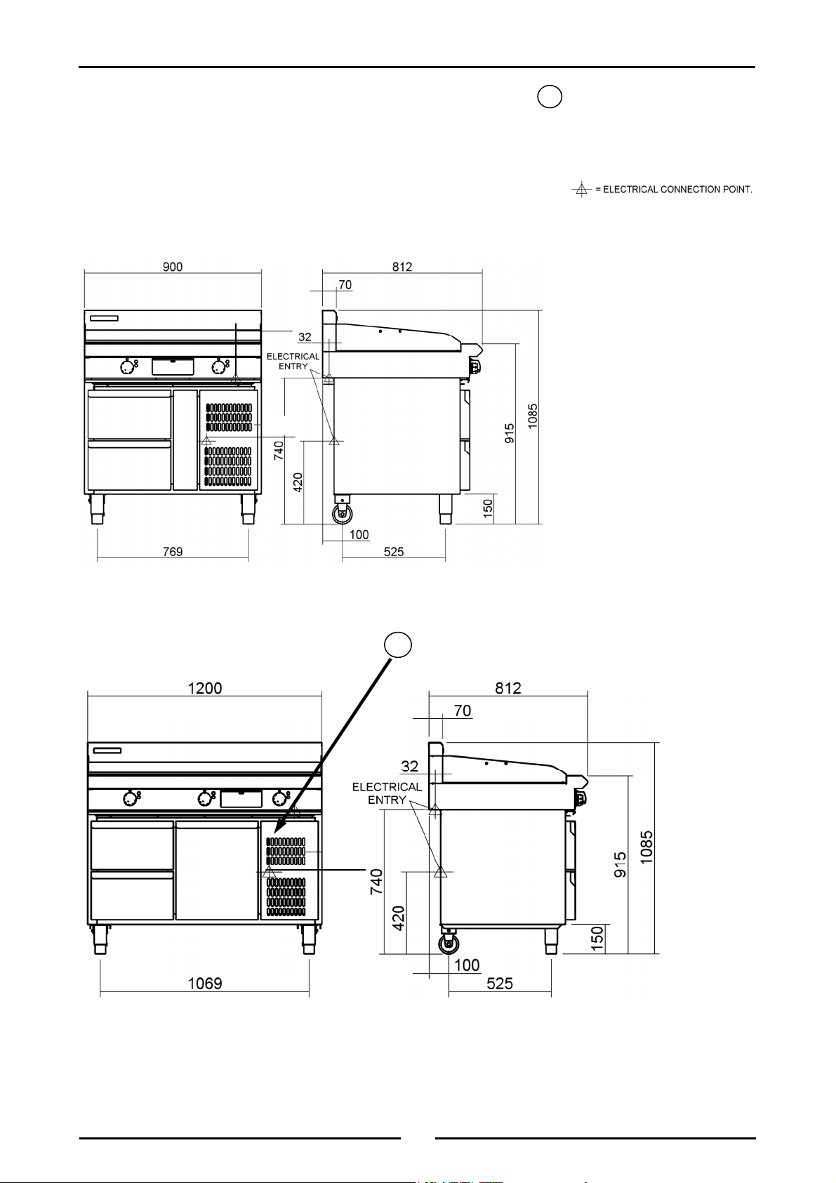
Dimensions
Dimensions for Refrigeration Base Models
EP516 - RB
130
280
= Rating Plate Location for
R
this option.
EP518 - RB
R
280
8
Page 11

Installation
Installation Requirements
NOTE:
• It is most important that this appliance is installed correctly and that operation is correct
before use. Installation shall comply with local electrical and health and safety
requirements.
• This appliance shall be installed with sufficient ventilation to prevent the occurrence of
unacceptable concentrations of health harmful substances in the room, the appliance is
installed in.
Blue Seal Electric Griddles are designed to provide years of satisfactory service and correct installation is
essential to achieve the best performance, efficiency and trouble-free operation.
This appliance must be installed in accordance with National installation codes and in addition, in
accordance with relevant National / Local codes covering electrical, fire and health and safety.
Australia / New Zealand AS / NZS3000 - Wiring Rules.
United Kingdom: BS 7671 - Requirements for Electrical Installations.
Installations must be carried out by qualified persons only. Failure to install equipment to the
relevant codes and manufacturer’s specifications shown in this section will void the warranty.
Components having adjustments protected (e.g. paint sealed) by the manufacturer are only
to be adjusted by an authorised service agent. They are not to be adjusted by the installation
person.
Unpacking
• Remove all packaging and transit protection from the appliance including all protective plastic
coating from the exterior stainless steel panels.
• Check equipment and parts for damage. Report any damage immediately to the carrier and
distributor.
• Ensure that the 4 adjustable feet are fitted with the protruding centre screw.
• Report any deficiencies to the distributor who supplied the appliance.
• Check that the available electrical supply is correct to that shown on the rating plate (Refer to the
dimension drawings for rating plate location).
Location
1. Installation must include adequate clearance and ventilation, to prevent dangerous build up of
combustion products.
2. Never directly connect a ventilation system to the appliance flue outlet.
3. Position the appliance in its approximate working position.
4. The legs (castors) must always be fitted to the base of the appliance.
5. Components having adjustments protected (e.g. paint sealed) by the manufacturer are only to be
adjusted by an authorised service agent. They are not to be adjusted by the installation person.
NOTE: Do not obstruct or block the appliances flue. Never directly connect a ventilation system to
the appliance flue outlet.
Clearances
Combustible Surface Non Combustible Surface
Left / Right Hand Side 100mm 0mm
Rear 50mm 0mm
NOTE: Only non-combustible materials can be used in close proximity to this appliance.
9
Page 12

Installation
Assembly
C
AUTION
•
This appliance is for professional use and is to be used by suitably
qualified / trained persons only.
•
Only qualified service persons are to carry out installation and servicing of
this appliance.
:
All Models
All models come pre-assembled.
NOTE: This appliance is fitted with adjustable feet (castors) to enable the unit to be positioned
securely and level. This should be carried out on completion of the electrical connection.
Refer to the 'Electrical Connection' section.
Optional Accessories (Refer to Replacement Parts List)
• Plinth Kit. For installation details, refer to the instructions supplied with each kit.
Electrical Connection
WARNING:
HIS APPLIANCE MUST BE EARTHED. IF THE SUPPLY CORD IS DAMAGED, IT MUST BE REPLACED BY A SUITABLY
T
QUALIFIED PERSON IN ORDER TO AVOID A HAZARD.
NOTE: ALL ELECTRICAL CONNECTIONS MUST ONLY BE CARRIED OUT BY AN QUALIFIED
PERSON.
Each appliance should be connected to an adequately protected power supply and isolation switch mounted
adjacent to, but not behind the appliance. This switch must be clearly marked and readily accessible in
case of fire.
1. Check that the electricity supply is correct as shown on the Rating Plate. (Refer to the dimension
drawings for rating plate location).
2. The supply terminal connections are located at the rear of the the appliance. Refer to ‘Electrical
Connections’ in the ‘Specifications’ section of the manual.
3. Remove the control panel to allow connection access for the electrical supply.
4. Bring the supply cable up through the grommet at the back of the appliance and through the
compression type gland provided on the rear of the main electrical switchgear panel.
5. Connect the mains supply to L1, L2 and L3 fuse carrier connections for 3 phase and L1 for single
phase (EP514).
6. Connect neutral and earth conductors to neutral stud and earth stud respectively.
7. For all connections ensure that conductors are secure and appropriately terminated.
8. Tighten the cable gland to secure against tension on the cable.
NOTE:
• This appliance must be grounded / earthed.
• Fixed wiring installations must incorporate an all-pole disconnection switch.
9. Correctly locate the appliance into its final operating position and using a spirit level, adjust the legs
so that the appliance is level and at the correct height.
10. Connect the power supply to the appliance.
11. Check that the electrical supply is as shown in the 'Specifications' section.
10
Page 13

Installation
Commissioning
1. Before leaving the new installation;
a. Check the following functions in accordance with the operating instructions specified in the
'Operation' section of this manual.
• Check the current draw and loading for the equipment. Refer to the 'Specification' section
for the correct electrical requirements.
• Check that all the connections are correct and that all cover panels have been re-fitted.
• Check that the appliance functions in accordance with the operating instructions.
• Ensure that this instruction manual is left with the appliance.
• Ensure that all the relevant details and contacts have been added to the front of this
manual.
b. Ensure that the operator has been instructed in the areas of correct operation and shutdown
procedure for the appliance.
2. This manual must be kept by the owner for future reference and as a record of
Date of Installation
details can be found on the Rating Plate. (Refer to the dimension drawings for rating
plate location).
NOTE:
• If for some reason it is not possible to get the appliance to operate correctly, turn off the
electrical power supply and contact a qualified service person. The supplier of this
appliance will be able to recommend a suitable person.
and
Serial Number of Unit
recorded and kept with this manual. (These
Date of Purchase,
• Make sure that the electrical supply is turned off before any service or maintenance work
is carried out.
For the Refrigeration Cabinet Installation refer to the Refrigeration Cabinet Installation and
Operation Manual supplied with the appliance.
11
Page 14
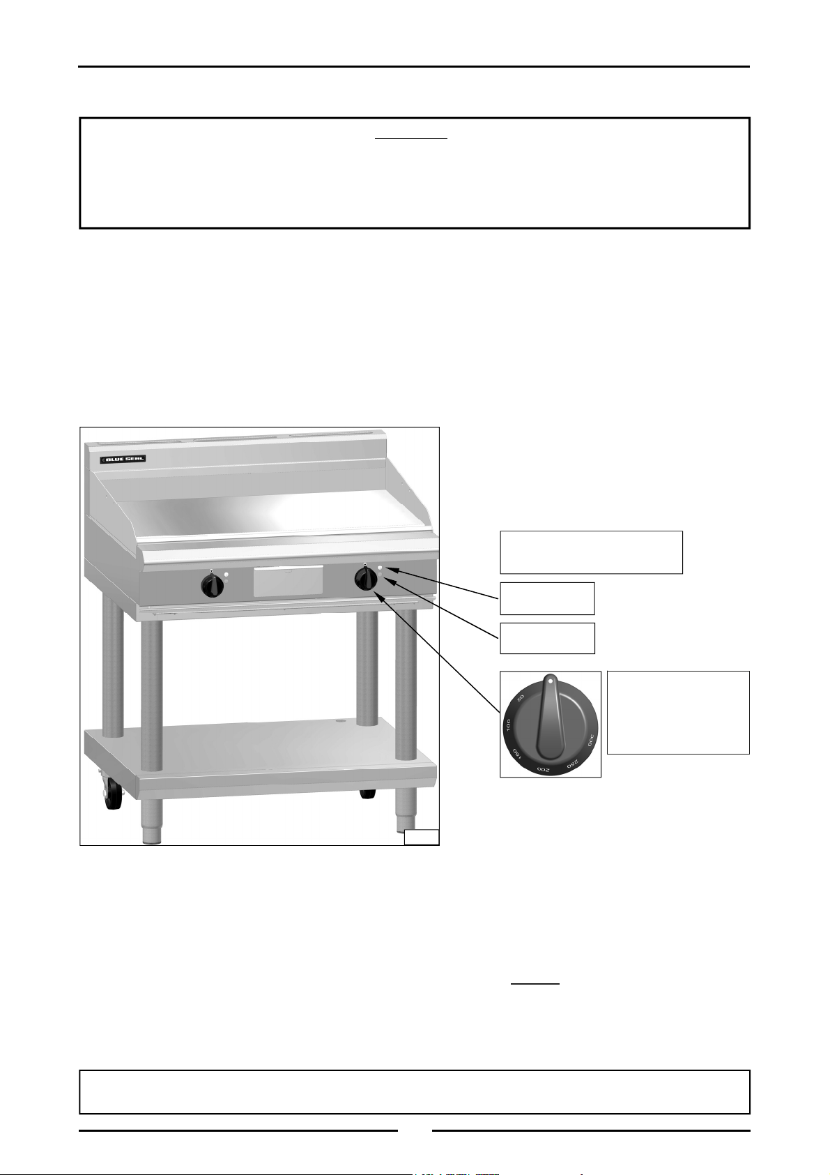
Operation
Operation Guide
C
AUTION
•
This appliance is for professional use and is only to be used by suitably
qualified / trained persons.
•
Only qualified service persons are allowed to carry out installation and
servicing of this appliance.
:
1. Blue Seal Electrical Griddles have been designed to provide simplicity of operation and 100% safety
protection.
2. Improper operation is therefore almost impossible, however bad operating practices can reduce the
life of the griddle and produce a poor quality product. To use this appliance correctly please read
the following sections carefully:-
• Griddle.
Description of Controls
Electric Griddle Controls
(Model EP516-LS shown)
Power Indicator
Lamps (white)
Heating Indicator
Lamps (Amber)
Control Knob
With temperature
Gradient of 50°C to
320°C
Fig 1
Griddle
1. Turn 'ON' the power at the mains supply, the white neon will illuminate.
2. Turn the thermostat control knob to the desired temperature. When the amber neon goes out, the
desired temperature has been reached and the griddle is ready for use.
NOTE: Turning the control to a higher setting than required will not shorten the heat up time.
3. To turn 'OFF' the griddle, turn the thermostat control knob to the lowest setting and turn 'OFF' the
mains power to the griddle.
4. Both the amber and white neons should not be illuminated.
For the Refrigeration Cabinet Operation refer to the Refrigeration Cabinet Installation and Operation
Manual supplied with the appliance.
12
Page 15

C
AUTION
Cleaning and Maintenance
:
Always turn off the electrical supply at the mains before cleaning.
This appliance is not water proof.
Do Not use water jet spray to clean interior or exterior of this appliance.
General
Clean the griddle regularly. A clean appliance looks better, will last longer and will perform better.
Carbonised grease on the surface or on the griddle plate will hinder the transfer of heat from the
cooking surface to the food. This will result in loss of cooking efficiency.
NOTE: Each Heavy Duty Griddle is supplied with a scraper tool and a pack of blades for cleaning
the griddle surface.
- 1 Flat Blade (pack) - 1 Ribbed Blade (pack) and 2 handles for Ribbed Heavy Duty Griddle.
- 1 Flat Blade (pack) and I handle for Smooth Heavy Duty Griddle.
NEVER use the ribbed scraper blade on the flat chrome surfaced griddle plate.
Replacement blades and handles can be purchased separately. Refer to the 'Replacement
Parts List' at the rear of the manual.
WARNING:
THE BLADES FITTED TO THE SCRAPER TOOL ARE EXTREMELY SHARP AND ARE TO BE USED WITH CARE.
DO NOT use water on the griddle plate while this item is still hot as warping and
cracking may occur. Allow the griddle plate to cool down before cleaning.
NOTE:
• DO NOT use abrasive detergents, strong solvents or caustic detergents as they could
corrode or damage the griddle.
• In order to prevent the forming of rust on the griddle plate (Steel Plate), ensure that any
detergent or cleaning material has been completely removed after each cleaning. The
appliance should be switched on briefly to ensure the griddle plate becomes dry. Oil or
grease should be spread over the griddle surface in order to form a thin protective greasy
film.
To keep your griddle clean and operating at peak efficiency, follow the procedures shown below:-
After Each Use
C
AUTION
Always ensure that an even pressure is applied over the whole surface of the
scraper tool when using on the flat chromed surface of the griddle, to prevent
scoring of the surface.
NEVER bang the sharp edge of the scraper tool on the flat chromed surface of
the griddle as this will damage the chrome finish and invalidate the warranty.
:
1. Clean the griddle with the supplied scraper tools to remove any food debris.
2. Always ensure that the scraper tool blades are changed regularly to ensure that the scraper tool
works efficiently and prevents damage to the griddle plate surface.
13
Page 16

Cleaning and Maintenance
Daily Cleaning
1. The grease drawer should be checked and emptied frequently to prevent overflow and spillage.
Remove the grease drawer while still warm so that the grease is in a liquid state. Empty any grease
from the drawer and wash thoroughly in the same manner as any cooking utensil.
2. Clean the Control Panel with a damp cloth lightly moistened with a solution of mild detergent and
water.
3. Thoroughly clean the splash back, the interior and exterior surfaces of the griddle with hot water, a
detergent solution and a soft scrubbing brush.
4. Brush the griddle surface with a soft bristled brush. Any carbon deposits should be removed using
the supplied scraper tool followed by wiping with a cloth to prevent accumulation of food
deposits.
5. Dry the griddle thoroughly with a dry cloth and polish with a soft dry cloth.
NOTE: Chrome Griddle Plate
; DO NOT use abrasive detergents, strong solvents or caustic
detergents as they could corrode or damage the chrome plate.
Weekly Cleaning
NOTE:
• If the griddle usage is very high, we recommend that the weekly cleaning procedure is
carried out on a more frequent basis.
• Ensure that protective gloves are worn during the cleaning process.
• DO NOT use harsh abrasive detergents, strong solvents or caustic detergents as they will
damage the griddle and burners.
• DO NOT use water on the griddle plates while they are still hot as warping may occur.
Allow these items castings to cool and remove for cleaning.
Griddle - Steel Plate
NOTE: In order to prevent the forming of rust on the griddle plate, ensure that all detergent and
cleaning material has been entirely removed after each cleaning process. The appliance
should be switched on briefly to ensure the griddle plate becomes dry. Oil or grease should
be spread over the griddle surface in order to form a thin protective greasy film.
a. Remove and clean the grease collection drawer frequently to prevent over spills.
b. Clean the griddle surface thoroughly with the supplied scraper tool or a wire brush. If necessary
use a griddle stone or a scotch bright pad on the griddle surface for the removal of stubborn or
accumulated carbon deposits.
c. Occasionally bleach the griddle plate with vinegar when the plate is cold.
d. Clean with hot water, a mild detergent solution and a scrubbing brush. Dry all components
thoroughly with a dry cloth.
e. The griddle should be switched on briefly to ensure that the griddle plate becomes dry. A thin
smear of cooking oil should be spread over the griddle in order to form a protective film.
Griddle - Chrome Plate
C
AUTION
Always ensure that an even pressure is applied over the whole surface of the
scraper tool when using on the flat chromed surface of the griddle, to prevent
scoring of the surface.
NEVER bang the sharp edge of the scraper tool on the flat chromed surface of
the griddle as this will damage the chrome finish and invalidate the warranty.
:
NOTE: In order to maintain the finish on the chrome griddle plate, ensure that all detergent and
cleaning material has been entirely removed after each cleaning process. The appliance
should be switched on briefly to ensure the griddle plate becomes dry.
14
Page 17

Cleaning and Maintenance
a. Remove and clean the grease collection drawer frequently to prevent over spills.
b. Clean the griddle surface thoroughly with the supplied scraper tool.
c. Allow the plate to cool, then clean the plate with a scrubbing brush, a mild non-abrasive
detergent and water.
d. Occasionally bleach the plate with vinegar when cold.
e. Dry the griddle thoroughly with a dry cloth and polish with a soft dry cloth.
f. The griddle should be switched on briefly to ensure that the griddle plate becomes dry.
Griddle Cooking Area
a. Clean the griddle cooking area with a soft cloth and a mild detergent and hot water solution.
b. Baked on deposits or discolouration may require a good quality stainless steel cleaner or stainless
steel wool. Always apply cleaner when the appliance is cold and rub in the direction of the grain.
c. Remove the grease drawer and clean with a mild anti bacterial detergent and hot water solution
using a soft bristled brush. Dry the grease drawer thoroughly with a dry cloth.
Stainless Steel Surfaces
a. Clean the exterior surfaces of the griddle with hot water, a mild detergent solution and a soft
scrubbing brush. Note that the control knobs are a push fit onto the spindles and can be
removed to allow cleaning of the front control panel.
b. Baked on deposits or discolouration may require a good quality stainless steel cleaner or stainless
steel wool. Always apply cleaner when the appliance is cold and rub in the direction of the grain.
c. To remove any discolouration, use an approved stainless steel cleaner or stainless steel wool.
Always rub in the direction of the grain.
d. Remove the grease tray and clean with a mild anti bacterial detergent and hot water solution
using a soft bristled brush.
e. Dry the grease tray thoroughly with a dry cloth.
f. Dry all components thoroughly with a dry cloth and polish with a soft dry cloth.
Periodic Maintenance
To achieve the best results, cleaning must be regular and thorough and all controls and mechanical
parts should be checked and adjusted periodically by a competent serviceman. If any small faults
occur, have them attended to promptly. Don't wait until they cause a complete breakdown. It is
recommended that the appliance is serviced every 6 months.
For the Refrigeration Cabinet Cleaning and Maintenance refer to the Refrigeration Cabinet
Installation and Operation Manual supplied with the appliance.
15
Page 18
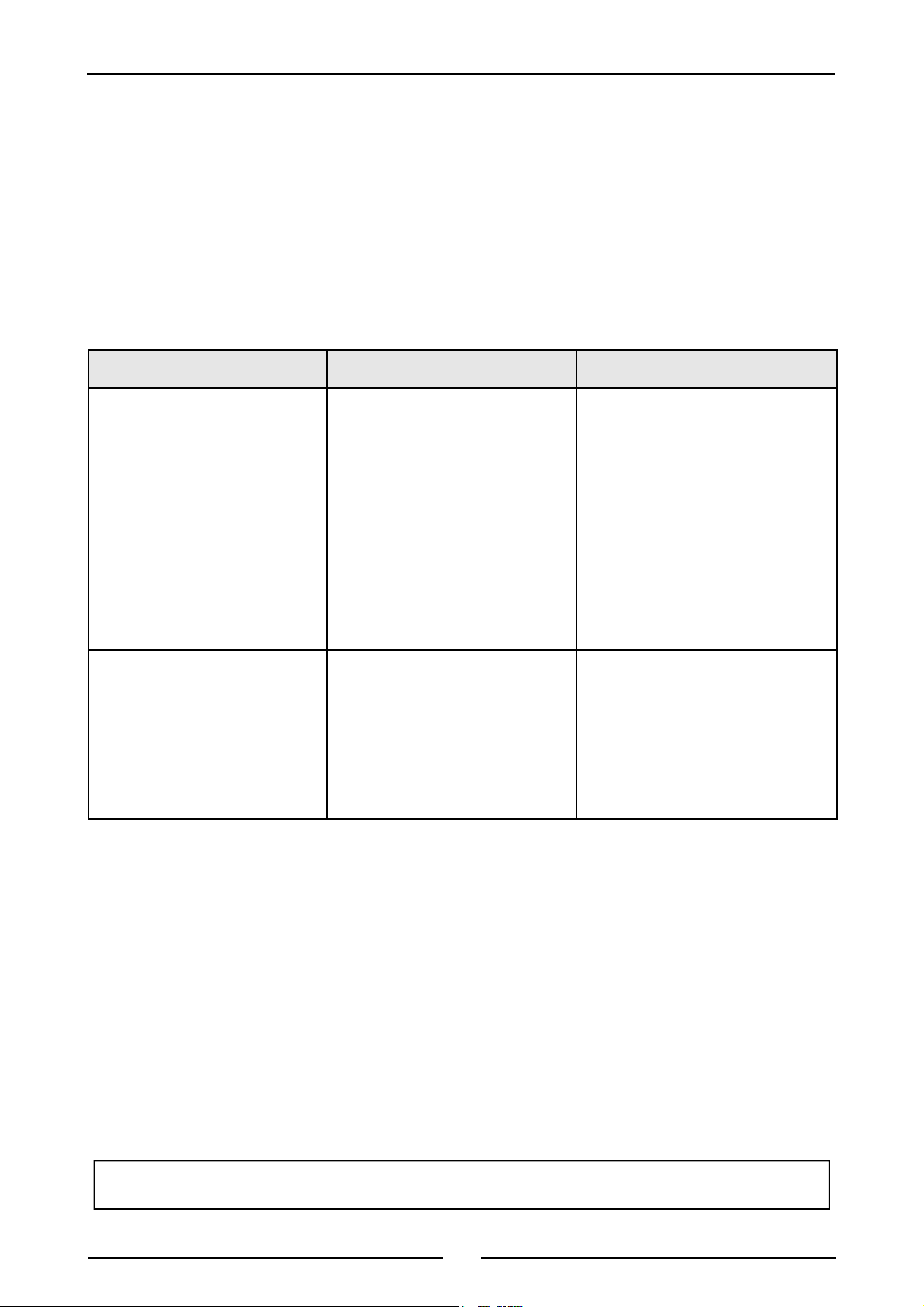
Fault Finding
This section provides an easy reference guide to the more common problems that may occur during the
operation of your equipment. The fault finding guide in this section is intended to help you correct, or at
least accurately diagnose problems with your equipment.
Although this section covers the most common problems reported, you may encounter a problem not
covered in this section. In such instances, please contact your local authorised service agent who will
make every effort to help you identify and resolve the problem. Please note that the service agent will
require the following information:-
• The Model Trade Name and the Serial Number of the Appliance. (both can be found on the
Technical Data Plate located on the appliance. (Refer to the ‘Dimensions’ section).
Fault Possible Cause Remedy
Element does not work when
turned ‘ON’.
Complete power failure of the
appliance
NOTE: Components having adjustments protected (e.g. paint sealed) by the manufacturer, are only
to be adjusted by an authorised service agent. They are not to be adjusted by an
unqualified service person.
Check individual fuses located
behind the control panel.
Check for an electrical short by
checking that there is NO
continuity between any 'Phase In'
line and the metal appliance
body itself.
Check for the item failing
(element, control etc) by using a
multimeter as shown on following
pages.
Check fuse connection at the
mains supply.
Ensure that the fuse size is
correct to carry the load.
Check for an electrical short to
the appliance.
Replace the blown fuse.
Call the service provider.
Replace the blown fuse.
Carry out a continuity and
resistance check on the appliance.
Call the service provider.
For the Refrigeration Cabinet Fault Finding details, refer to the Refrigeration Cabinet Installation
and Operation Manual supplied with the appliance.
16
Page 19
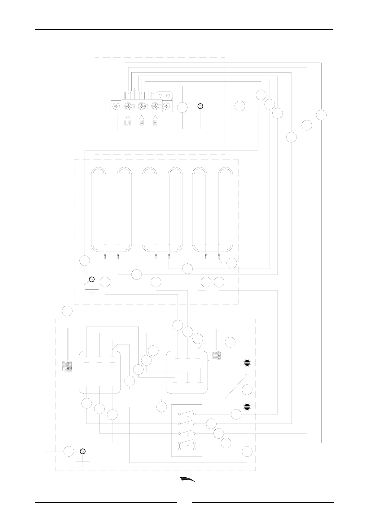
EP514 Wiring Schematic
Circuit Schematics
REAR SUPPLY ENTRY
13
EARTH
STUD M6
15
13
LABEL 019207
8
7
7 6
8
8
10
8
8
8
9
9
9
14
32
31
14
CONTROL PANEL
EARTH STUD M6
GRIDDLE PLATE
22
12
21
11
OVERTEMP
1
1
THERMOSTAT
229353
1
EARTH STUD
3/16"
7
7
6
3
2
2
4
11
SWITCH
229145
31
22
32
4
3
2
1
21
12
11
P4
P3
P2
P1
THERMOSTAT
229146
NEON GREEN
227962
9
5
NEON
AMBER
227963
12
10
9
9
4
17
Page 20
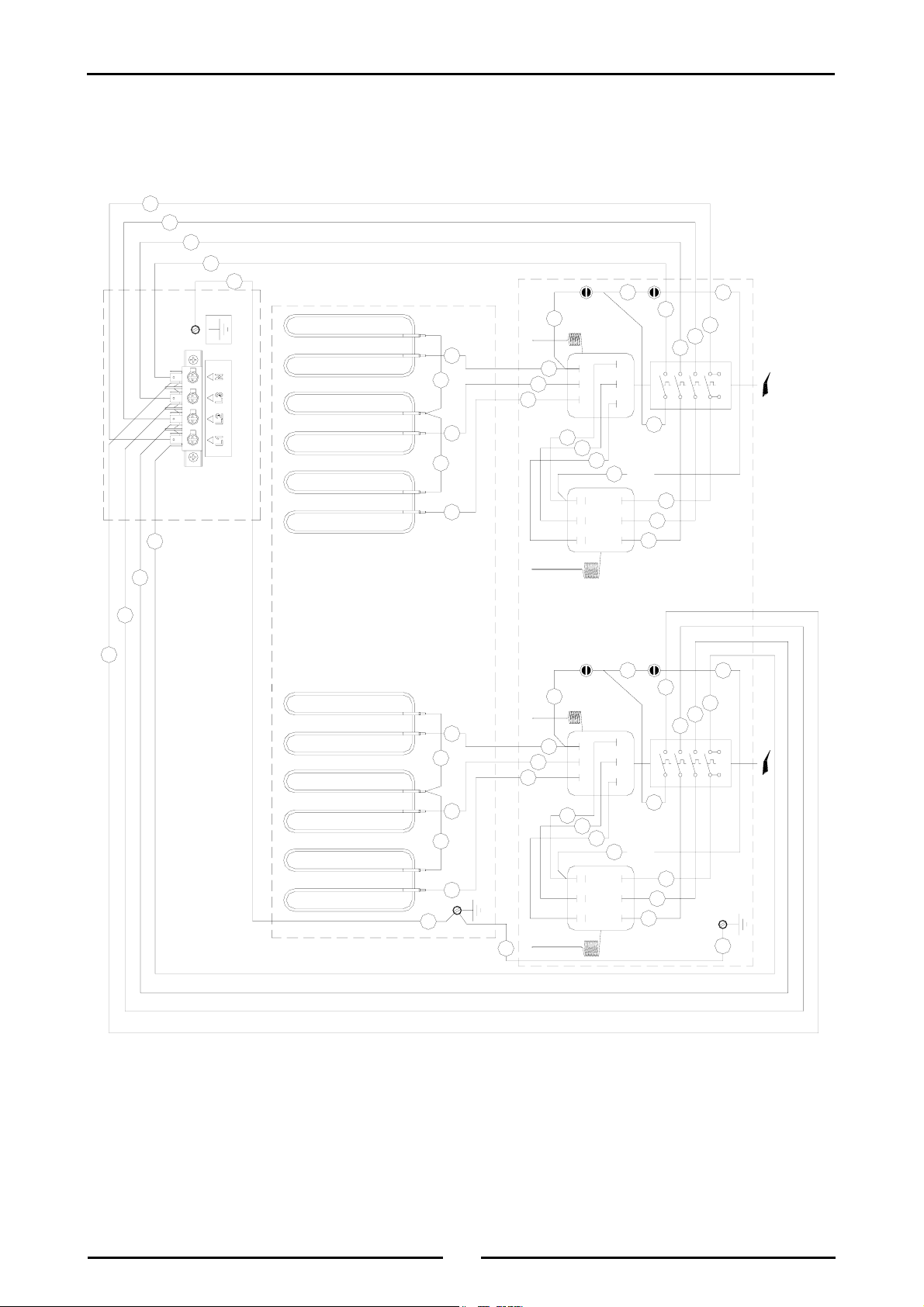
Circuit Schematics
EP516 Wiring Schematic
9
9
9
11
15
STUD M6
EARTH
REAR SUPPLY ENTRY
10
LABEL 229043 LABEL 19234
5
AMBER
227963
NEON
6
7
88
GRIDDLE PLATE
7
6
7
7
12
2232
3
2
22
32 12
14
11
THERMOSTAT
229146
227962
NEON GREEN
11
P4
21
31
13
2
4
THERMOSTAT
229353
OVERTEMP
11
21
31
1
1
1
4
9
9
9
P1
P2
2
3P34
1
229145
SWITCH
CONTROL PANEL
10
10
12
14
5
6
7
88
7
15
EARTH STUD M6
6
7
7
3
16
AMBER
227963
NEON
THERMOSTAT
229146
12
2232
2
2
4
11
21
22
31
32 12
12
227962
NEON GREEN
11
P4
21
31
13
THERMOSTAT
229353
OVERTEMP
1
1
1
4
10
10
10
P1
P2
3P34
2
1
229145
SWITCH
3/16"
EARTH STUD
16
18
Page 21
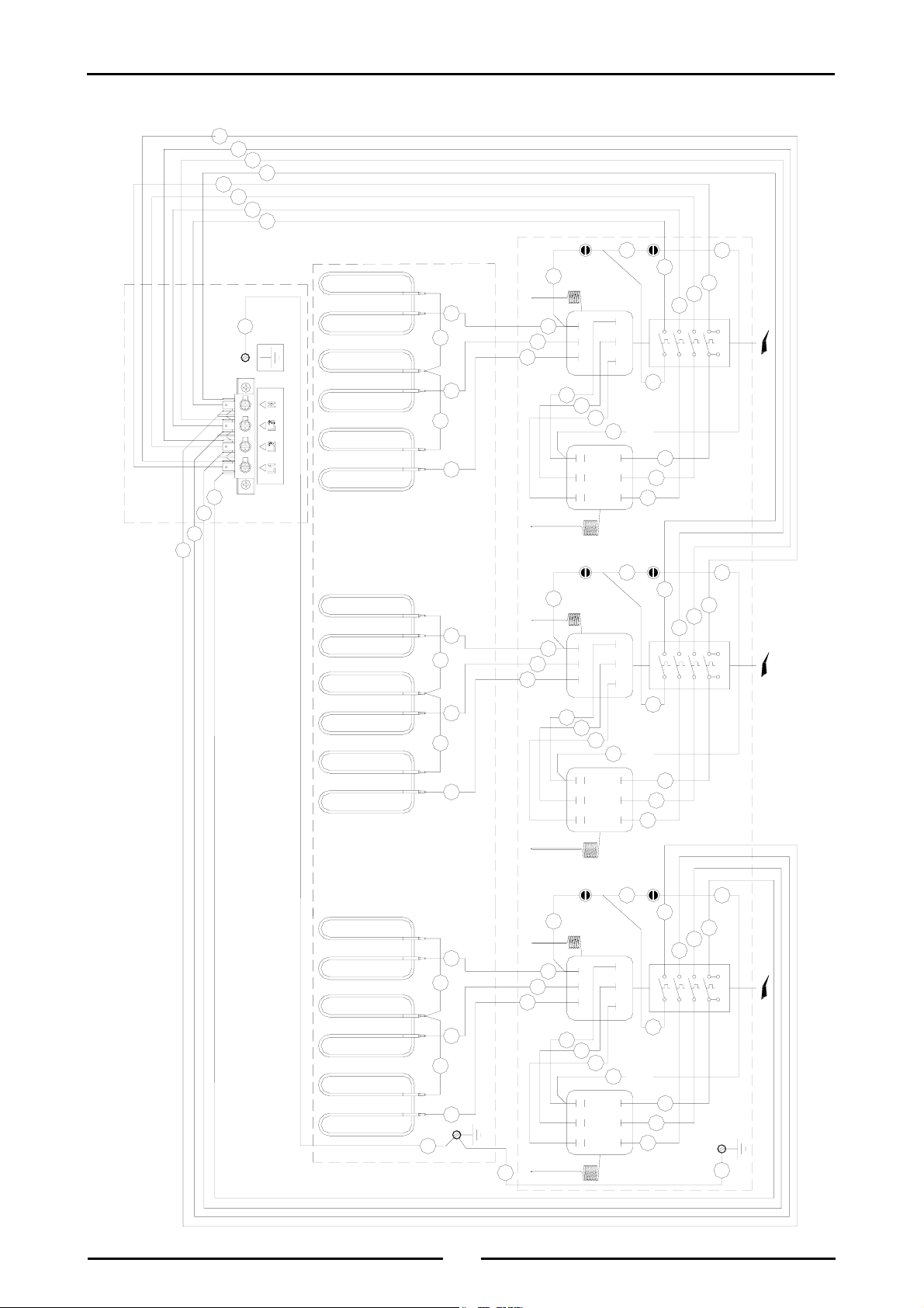
EP518 Wiring Schematic
10
10
10
13
9
9
9
12
Circuit Schematics
16
5
AMBER
227963
NEON
THERMOSTAT
229146
17
STUD M6
EARTH
REAR SUPPLY ENTRY
11
11
11
14
LABEL 19234
LABEL 229043
76
88
GRIDDLE PLATE
7
76
88
7
6
7
7
7
7
22
32 12
3
2
2
4
11
12
2131
2232
5
AMBER
227963
NEON
THERMOSTAT
229146
6
22
32 12
3
2
2
4
11
12
2131
2232
12
227962
NEON GREEN
11
P4
21
31
15
THERMOSTAT
229353
OVERTEMP
2
2
2
16
13
227962
NEON GREEN
11
P4
21
31
15
THERMOSTAT
229353
OVERTEMP
1
1
1
4
9
9
9
P1
P2
3P34
2
1
229145
SWITCH
CONTROL PANEL
4
10
10
10
P1
P2
3P34
2
1
SWITCH
229145
5
6
7
7
76
88
7
17
EARTH STUD M6
18
3
19
16
AMBER
227963
NEON
THERMOSTAT
229146
22
32 12
2
2
4
11
12
2131
2232
14
227962
NEON GREEN
11
P4
21
31
15
THERMOSTAT
229353
OVERTEMP
1
1
1
4
11
11
11
P1
P2
3P34
2
1
229145
SWITCH
3/16"
EARTH STUD
18
Page 22

Replacement Parts List
Replacement Parts List
IMPORTANT:
Only genuine authorized replacement parts should be used for the servicing and
repair of this appliance. The instructions supplied with the parts should be followed
when replacing components.
For further information and servicing instructions, contact your nearest authorized
service branch (contact details are as shown on the reverse of the front cover of this
manual).
When ordering replacement parts, please quote the part number and the description as listed below. If the
part required is not listed below, request the part by description and quote model number and
serial number which is shown on the rating plate.
Controls
227392 Control Knob - 50°C to 300°C.
229146 Thermostat - 50°C to 300°C.
229353 Overtemp 360°C, 3 Pole.
229145 Switch 4 Pole.
228922 Neon White.
227963 Neon Orange.
228571 Index Mark Moulding.
General
Accessories
229213 Element 2400W (600mm Models).
229245 Element 2000W (900 - 1200mm Models).
228400 Grease Drawer.
227851 Leg 150mm (Adjustable).
227855 Leg 80mm (Bench Models Only).
229674 Rear Roller Assy.
229224 Control Panel Hinge.
232351 Rear Roller Assy (3 inch).
227850 Leg 150mm (Flush Stud).
228566 Griddle Scraper Tool.
228567 Smooth Plate Scraper Blades (Pack of 5 blades).
228568 Ribbed Plate Scraper Blade (Individual Blade).
228795 600mm Plinth Kit (LS and CB Models only).
228799 900mm Plinth Kit (LS and CB Models only).
228803 1200mm Plinth Kit (LS and CB Models only).
228801 Refrigeration Base - 900mm Plinth Kit (RB Models only).
228805 Refrigeration Base - 1200mm Plinth Kit (RB Models only).
For the Refrigeration Cabinet Replacement Parts refer to the Refrigeration Cabinet Installation and
Operation Manual supplied with the appliance.
20
Page 23

Replacement Parts List
Griddle Plate Options
Griddle Plate Standard Chromed (-C) Ribbed
600mm 229212 229267
900mm 229248 229270
1200mm 229279 229281
ON REQUEST,
Various options (depending on ribbed
section width on LH or RH side).
21
Page 24

 Loading...