

Page 1

INSTALLATION / OPERATION
E85 PROVER
MANUAL
F21804-8
Page 2

MANUFACTURED BY
Moffat Limited
PO Box 10001
Christchurch
New Zealand
Ph: (03) 389 1007
Fax: (03) 389 1276
WORLD-WIDE BRANCHES
UNITED KINGDOM
Blue Seal
Units 6-7, Mount Street Business Park
Mount Street, Nechells
Birmingham B7 5QU
Ph: (121) 327 5575
Fax: (121) 327 9711
UNITED STATES
Moffat Inc
3765 Champion Blvd
Winston-Salem
North Carolina 27115
Ph: (336) 661 0257
Fax: (336) 661 9546
CANADA
Serve Canada
22 Ashwarren Road
Downview
Ontario M3J1Z5
Toll Free:800 263 1455
Ph: (416) 631 0601
Fax: (416) 631 0315
[email protected]
www.servecanada.com
www.moffat.com
NEW ZEALAND
Christchurch
Moffat Limited Moffat Limited
PO Box 10-001 4 Waipuna Road
16 Osborne Street Mt Wellington
Christchurch Auckland
Ph: (03) 389 1007 Ph: (09) 574 3150
Fax: (03) 389 1276 Fax: (09) 574 3159
AUSTRALIA
Victoria
Moffat Pty Limited Moffat Pty Limited
740 Springvale Road 3/142 James Ruse Drive, Rose Hill
Mulgrave, Melbourne PO Box 913, Smithfield
Victoria 3171 Sydney, N.S.W. 2142
Ph: (03) 9518 3888 Ph: (02) 8833 4111
Fax: (03) 9518 3838 Fax: (02) 8833 4133
Western Australia
Moffat Pty Limited Moffat Pty Limited
67 Howe Street 30 Prosperity Place
Osbourne Park Geebung, Brisbane
WA 6017 Queensland 4034
Ph: (08) 9202 6820 Ph: (07) 3630 8600
Fax: (08) 9202 6836 Fax (07) 3630 8623
Auckland
New South Wales
Queensland
The reproduction or copying of any part of this manual by any means whatsoever is strictly forbidden unless authorized previously in
writing by the manufacturer.
In line with policy to continually develop and improve its products, Moffat Ltd. reserves the right to change the specifications and
design without prior notice.
© Copyright Moffat Ltd. November 2006.
Page 3

Contents
Introduction ........................................................................................................2
Installation..........................................................................................................3
Before Connection
Location
Electrical Connection
Water Connection (Auto Fill Models Only)
Rack Width
Stacking Instructions
Specifications.....................................................................................................5
Operation............................................................................................................9
Description of Controls
Condensation Channel
Operating the Prover
Bake-Off
Problem Solving
Hints
Cleaning and Maintenance.............................................................................. 13
Trouble Shooting .............................................................................................14
Spare Parts.......................................................................................................15
Circuit Schematics...........................................................................................16
E85 Prover (Manual Fill)
E85A Prover (Auto Fill)
Date Purchased................................................................. Serial No ..........................................................
Dealer............................................................................................................................................................
Service Agent ................................................................................................................................................
1
Page 4

Introduction
We are confident that you will be delighted with your E85 PROVER, and it will become a most valued
appliance in your commercial kitchen.
A new oven can seem very complex and confusing at first glance. To ensure you receive the utmost
benefit from your new Prover, there are two important things you can do.
Firstly
Please read the instruction book carefully and follow the directions given. The time taken will be well
spent.
Secondly
If you are unsure of any aspect of the installation, instructions or performance of your prover, contact your
E85 dealer promptly. In many cases a phone call could answer your question.
2
Page 5
Installation
Installation Requirements
It is most important that this prover is installed correctly and that operation is correct
before use.
Installation shall comply with local electrical, health and safety requirements.
Before Connection to Power Supply
• Remove all packing.
• Check equipment and parts for damage. Report any damage immediately to the carrier and
distributor.
• Remove protective plastic coating from the side panels.
• Check that the available power supply is correct to that shown on the rating plate located on the
right -hand side panel.
E85 220-240 Volts A.C, 50 Hz, 1P+N+E, 1.65 kW, 7.2A
Location
• To ensure correct ventilation for the motor and controls the following minimum installation
clearances are to be adhered to:
Rear 0mm / 0”
Left-hand side 0mm / 0”
Right-hand side 25mm / 1”
Electrical Connection
• E85 provers are supplied with pre-fitted cords. Ensure unit is fitted with appropriate cord and plug.
• To access the electrical connection terminal block, grounding lug and strain relief, remove the
right hand side panel.
WARNING - THIS APPLIANCE MUST BE EARTHED / GROUNDED
Water Connection (Auto Fill Models Only)
• A cold water supply should be fitted to the water inlet (¾” BSP connection) which is located near
the rear of the right hand side of the unit.
• Alternately, a connection elbow and sealing washer is supplied with this unit for direct connection
of a ½” ID hose, and is recommended for easy installation and service.
• Connect water supply - Max inlet pressure 80psi / 550kPa.
• Turn on water supply to check for leaks.
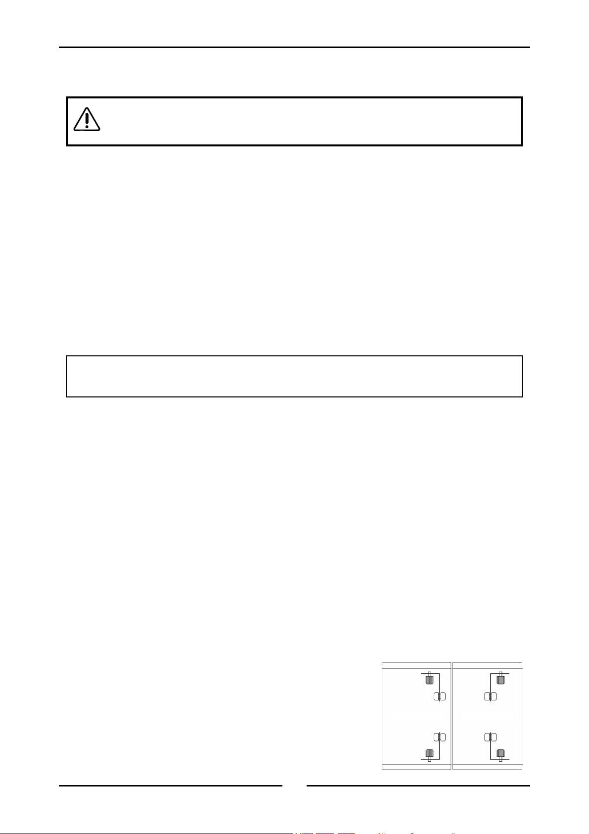
Rack Width
• The E85 prover has been designed to accept either 18” or
16” wide trays.
• The prover comes factory set for 18” trays, to change to 16”
trays:
• Remove the RH side rack (lift and extract).
• Undo the thumb screws (A) holding the RH rack
supports (B) and turn RH rack supports around, then
re-secure with thumbscrew.
3
A
For 18” trays
A
B
B
B
For 16” trays
B
A
A
Page 6
Installation
Stacking Instructions
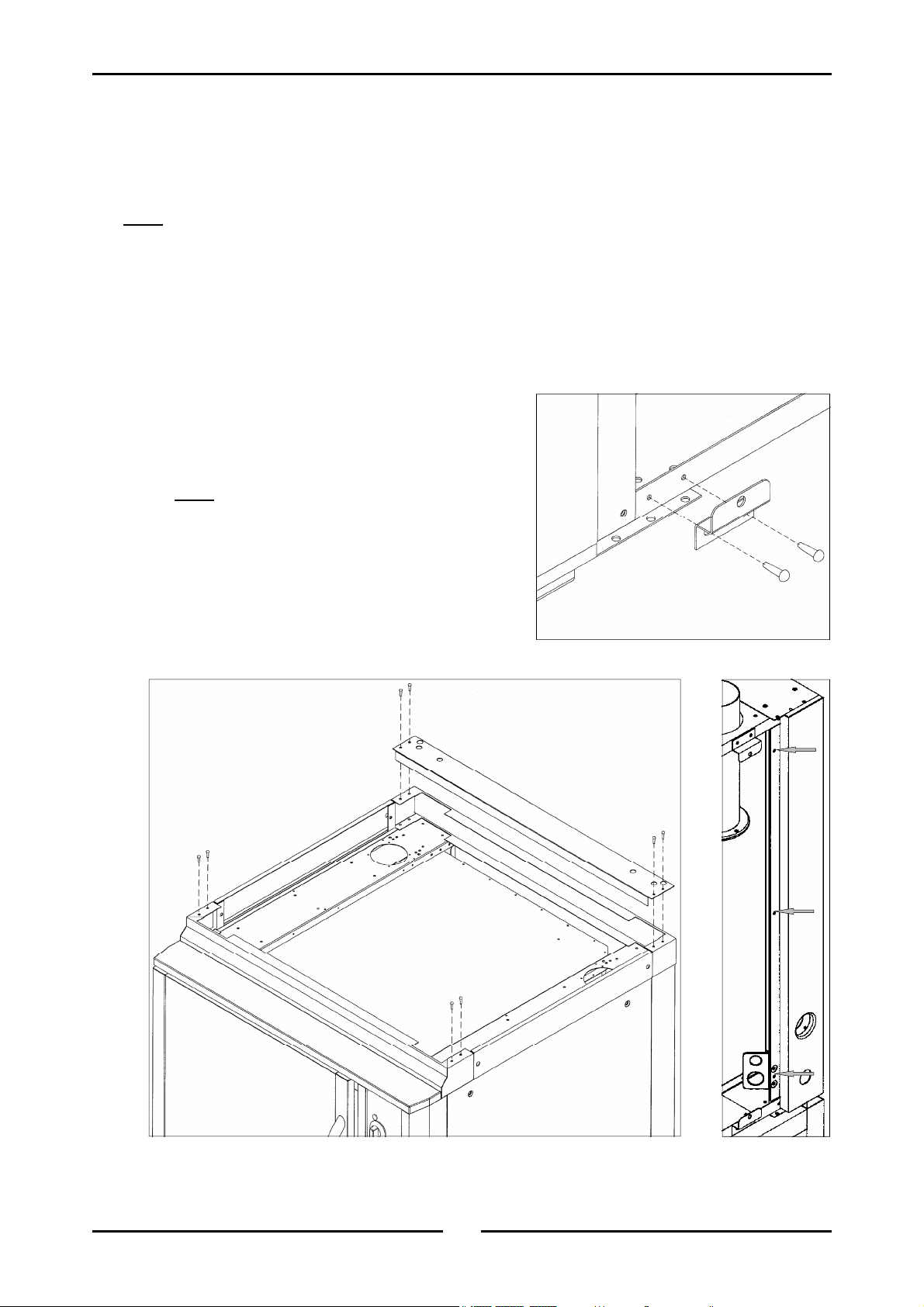
• The E85 prover has been designed to be stacked underneath E35 Turbofan Ovens.
• The prover comes with the stacking assembly ready to place an E35 on top, unless specified at
time of order to be fitted with a top panel for stand alone use.
When stacking on an E85 prover, the legs on an E35 Turbofan oven should not be fitted.
Note:
1) For 26” oven only, Remove rear spacer panel (A) from stacking kit by removing four screws
(B). (Retain screws - discard panel)
2) Position oven onto prover (on stacking kit) with front and sides flush with prover.
3) Remove side panels from oven (each side panel is held on by four screws).
4) 26” Oven - Remove rear RH side corner panel (power and water entry points), secured with
three screws at front edge of panel (D).
5) Remove the two front bottom side panel support
brackets (E), two screws (F) each.
6) Secure oven to prover using two screws (B / C) in
each corner of the unit (down from the sides).
Note:
corners only.
7) Replace side panel support brackets (E) at
bottom front of oven, using original screws (F).
8) Replace rear RH panel (D) on oven using
original screws (26” oven only).
9) Replace side panels, using original screws.
26” oven in all corners, 30” oven front
E
F
C
4
A
B
D
Page 7
Specifications
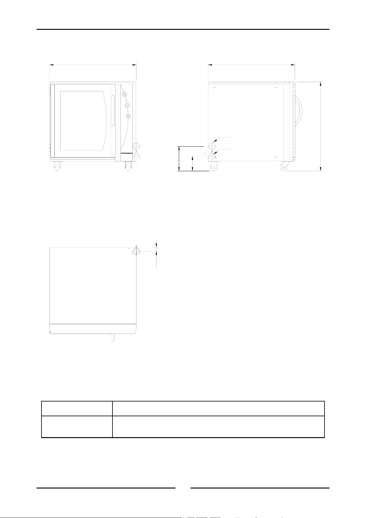
E85-8 Prover
880
Front
880
902
WATER ENTRY
MWS
E
1
MWS
E
1
ELECTRICAL ENTRY
250
150
Side
E
1
MWS
40
Plan
Electrical Connection 220-240 Volts A.C, 50 Hz, 1P+N+E, 1.65 kW, 7.2 A
Cold Water Connection
(Auto Fill Models Only)
¾” B.S.P. or 1/2 ID hose (550kPa / 80psi maximum pressure)
5
Page 8
Specifications
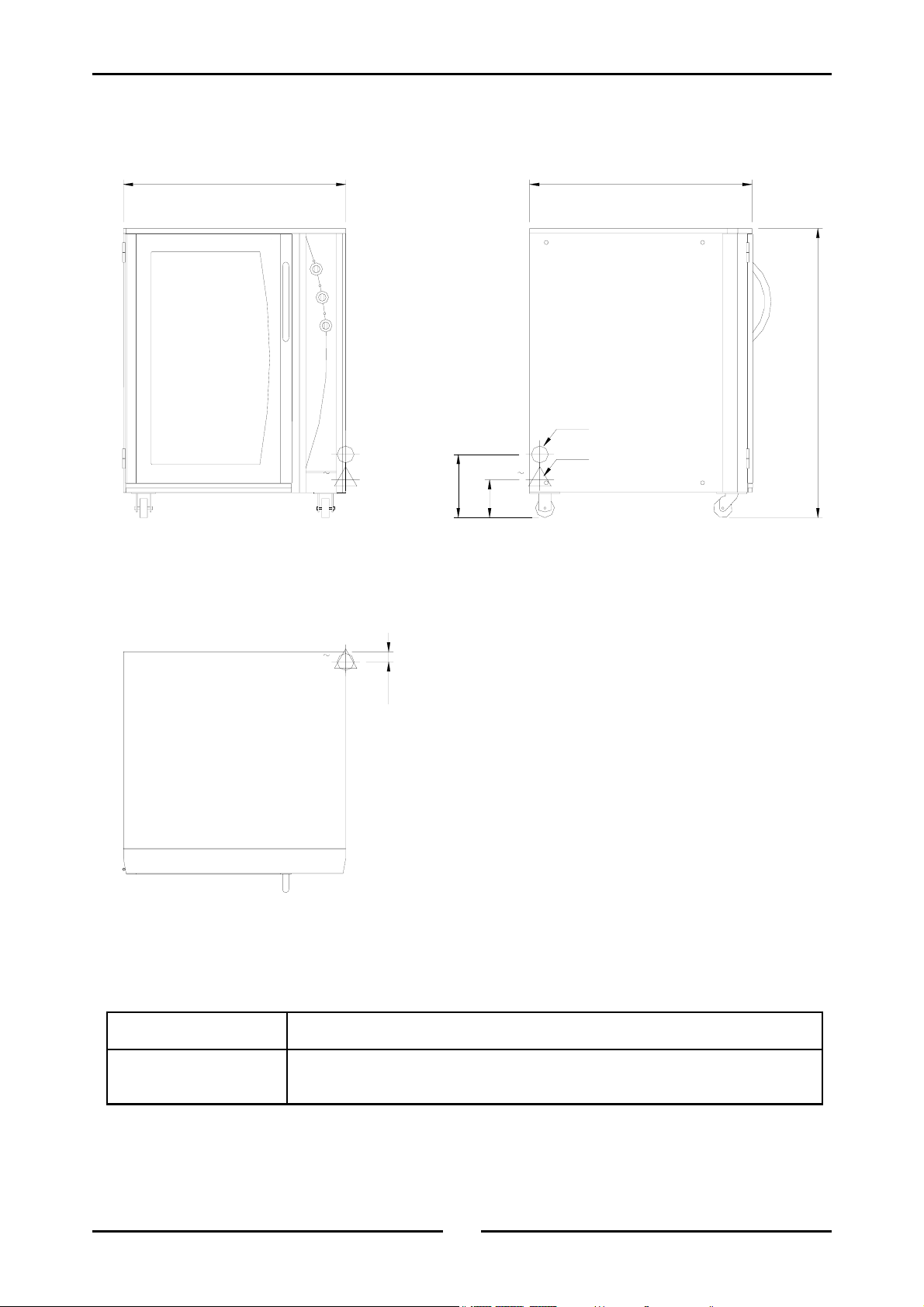
E85-12 Prover
880
Front
880
1145
WATER ENTRY
MWS
E
1
MWS
E
1
ELECTRICAL ENTRY
250
150
Side
E
1
40
Plan
Electrical Connection 220-240 Volts A.C, 50 Hz, 1P+N+E, 1.65 kW, 7.2 A
Cold Water Connection
¾” B.S.P. or 1/2 ID hose (550kPa / 80psi maximum pressure)
(Auto Fill Models Only)
6
Page 9
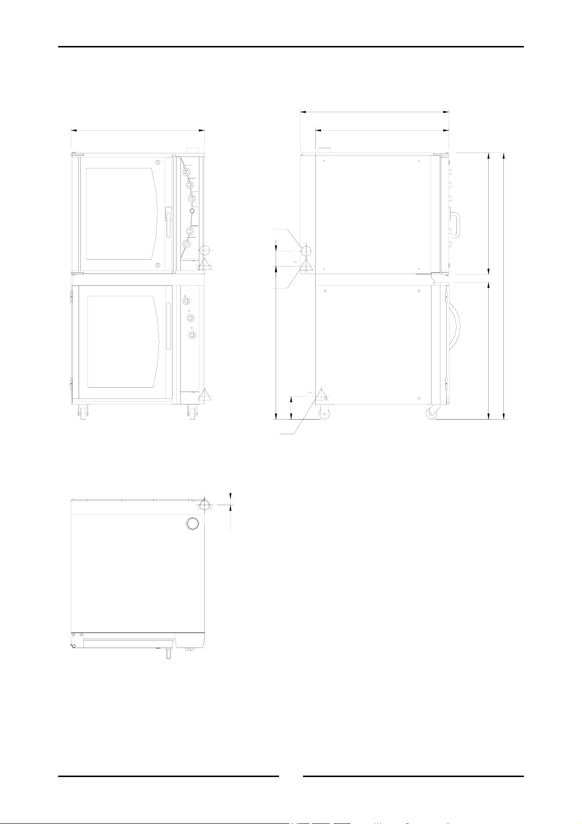
Specifications
E85-8 Prover / E35 Oven
880
MWS
E
3
ELECTRICAL ENTRY
WATER ENTRY
1006.5 100
980 (30" Ovens)
880 (26" Ovens)
800
MWS
E
3
1753
902
Front
E
1
E
1
150
ELECTRICAL ENTRY
Side
E
3
MWS
40
Plan
7
Page 10
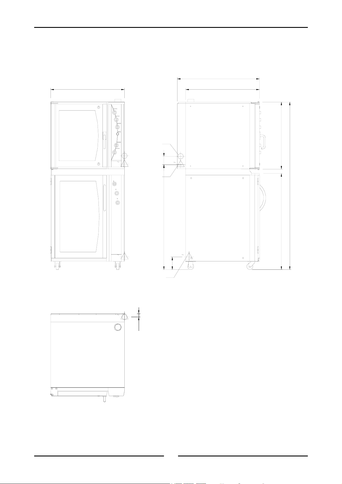
Specifications
E85-12 Prover / E35 Oven
880
MWS
E
3
ELECTRICAL ENTRY
WATER ENTRY
980 (30" Ovens)
880 (26" Ovens)
800
MWS
E
3
1001250
2000
Front
E
1
E
3
ELECTRICAL ENTRY
MWS
40
150
1145
E
1
Side
Plan
8
Page 11
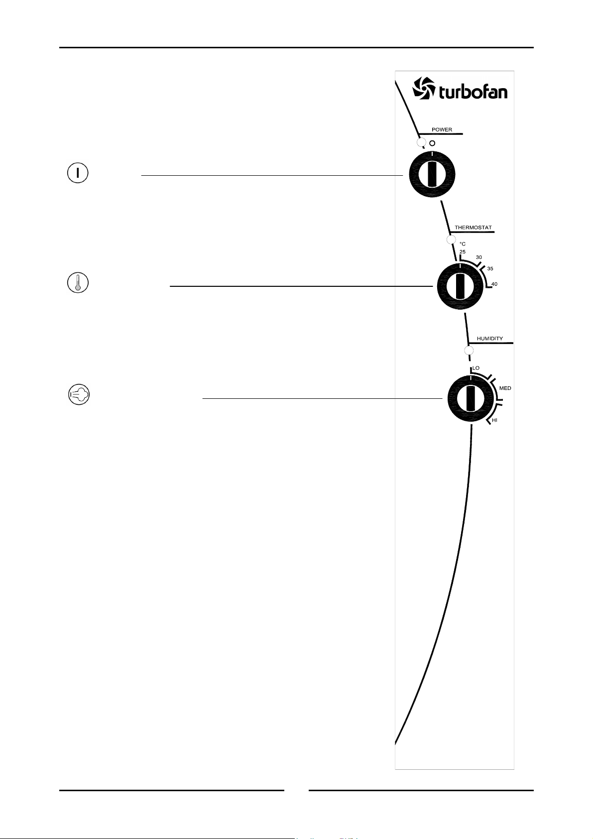
Operation
Operation Guide
Description
Power
Turn to switch power on or off (on horizontal, off
vertical). Indicator illuminates when power is on.
Thermostat
Temperature range 25-40°C (75 - 105°F).
Indicator illuminates when the elements are cycling
ON to maintain set temperature.
(Controls the prover air temperature)
of
Controls
85
l
Humidity Control
LO - Humidity setting for butter based pastries
(croissants, Danish pastries etc.)
MED/HI - Humidity setting for yeast based breads
and doughs.
Indicator illuminates when elements are cycling ON
to maintain set temperature.
(Controls the prover humidity)
Condensation channel
There is a condensation channel below the prover door
for the purpose of collecting door condensation run-off.
A diameter 12.7mm (½”) drain outlet is provided in the
centre of this channel and is factory fitted with a drain
bung. The drain facility can be used in three ways:
• Remove the bung when emptying is required and
drain into collection vessel. Refit bung until
drainage is next required.
• Place a suitable collection vessel or pan on the
floor below the drain outlet and remove bung
permanently for continual draining. Empty
collection vessel or pan as required.
• Remove the bung and connect a 12.7mm (½”) I.D.
hose or similar to drain outlet and route hose to
permanent drainage.
9
Page 12

Operation
Operating the Prover
Ensure that power is supplied to the unit and the water trough is filled
It is recommended that the prover operates empty before loading with product
- Warm days up to 10 minutes
- Cool days up to 30 minutes
1. Ensure water tank is filled with water
Standard models: Open the prover door and fill the water tank located at the front of the right
hand side rack. The tank should be filled to 20mm (¾”) from the top of the tank. Remember
to top up the water tank when the water level is below the halfway level in the tank (before
the heating element is exposed).
Auto fill models: Check that the water tank is full and that the heating element is well
covered.
2. Turn power on
The indicator light will illuminate whenever the switch is in the “I” (on) position.
3. Set thermostat to desired proving temperature
The indicator light will illuminate whenever the elements are cycling on to maintain the set
temperature.
25-30°C Butter based pastries
35-40°C Yeast based breads and doughs
4. Set humidity to desired level
The indicator light will illuminate whenever the elements are cycling on to maintain the set
humidity.
As a guide;
Set humidity to between ‘LO’ and MED’ marks on control panel as a general rule.
Increase or decrease as found necessary for specific product types.
Humidity is required only to avoid product dry skinning on surface. Do not set humidity
such that product becomes sticky and wet on surface. A silky to touch surface on the
product is a general recommendation for correct humidity levels.
Avoid excess humidity levels as this will also create excess condensation in the cabinet
interior.
Note:
Butter based product require much less humidity than breads.
10
Page 13

Operation
Bake-Off
This prover has been designed for use together with a refrigerator and oven to take frozen uncooked
yeast or butter based products to finished cooked products.
1. Prepare product
Arrange frozen products onto baking trays.
2. Thaw
Refrigerate at 4°C (40°F) overnight. Do not leave standing at room temperature or the product may
3. Prove
Place thawed products directly from the refrigerator into the pre-heated prover. Prove for 30-60
4. Bake
Place proved product directly from the prover into the pre-heated oven. We recommend the E35
dry out.
minutes dependant on product and food proving recommendations.
Turbofan Oven.
11
Page 14

Operation
Problem Solving
Product collapses
When using frozen dough which collapses or shrinks in the oven after proving, this is caused by too
much proving. Reduce the proving time for the next batch.
Dry product
The dough piece in the prover should never be dry to the touch. A moist, firm and silky membrane
should cover the dough piece during proving.
Wet product
The dough piece in the prover should not be wet to touch whilst proving and should not adhere to
fingers. Water should not condense on the trays. If it does there is either too much moisture or too
little heat in the prover.
If there are any problems with your dough the most likely causes are as follows:
• Too much heat and too little moisture.
• Not enough heat and too much moisture.
• Proving time too long or too short.
• Incorrect oven temperature.
• Incorrect maturity adjustment in the formulation of the dough for the flour.
• Incorrect thawing procedure, or handling of the dough after thawing.
Hints
Heat
It is better to operate the prover at a lower temperature with adequate moisture rather than at a
hotter temperature with too little moisture.
Yeast
Yeast activity starts very slowly at about 5°C (41°F) and increase in speed or gas production as the
temperature rises. When a temperature of approximately 60°C (140°F) is reached, the yeast is
killed and baking of the aerated product starts. Thus different rates of proving occur as the
temperature changes.
Flour
The amount of proving required is determined by the quality of the GLUTEN in the flour. Gluten is
a rubber like product and can perish if stretched too far by too much proving. Collapsing of the
product or shrinkage will occur.
Proof
You must recognise the proof of the product by the appearance of the dough rather than the size.
12
Page 15

Cleaning Guidelines
Cleaning
Caution:
ALWAYS TURN OFF THE POWER SUPPLY BEFORE CLEANING.
THIS UNIT IS NOT WATER PROOF.
DO NOT USE WATER JET SPRAY TO CLEAN INTERIOR OR EXTERIOR OF THIS UNIT.
Cabinet
Clean with a good quality stainless steel cleaning compound. Harsh abrasive cleaners may damage
the surface.
Side racks
To remove, take hold of the centre rung and lift upwards to disengage the rack key-holes from the
hanger studs. To replace, hold horizontally, engage keyholes onto studs and push down.
Door
Wash with warm water and detergent solution using a soft sponge in straight lines up and down the
door. Rinse with clean, warm water and dry off.
Water tank
Remove the RH side rack and remove tank by lifting off its hanger studs. Clean with warm soapy
water. Rinse thoroughly and refit.
Water tank element
When the element becomes limed/scaled remove the water trough and clean. Replace water trough
and half fill with white vinegar or acetic acid, then fill to the normal level with water. Switch the unit on,
turn the humidity to HI and operate for approximately 30 minutes. Remove trough and clean the
element with a damp cloth when cooled. Rinse out the through and refit to unit.
This procedure is recommended to be carried out once a week. Frequency of cleaning the element
may be increased or decreased depending on the lime depositing on the element.
13
Page 16
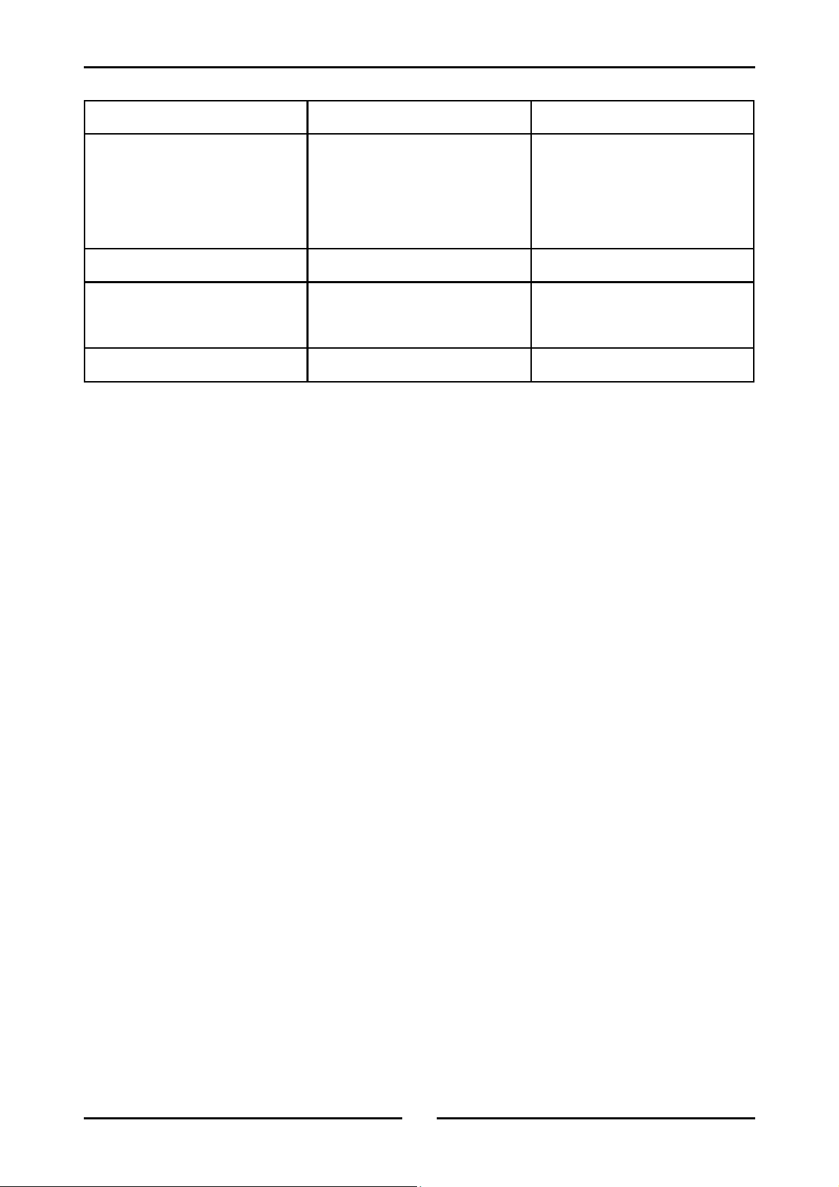
Trouble-shooting
Fault Possible Cause Remedy
The prover does not operate /
start.
No humidity. No water in trough. Fill with water.
Slow recovery. Overloading of prover.
Door does not close. Tray in way of door. Correctly position tray in rack.
The mains isolating switch on the
wall, circuit breaker or fuses are
“off” at the power board.
The power switch on the prover is
off.
Door opened unnecessarily.
Turn on.
Rotate switch. Indicator will
illuminate.
Reduce batch size.
Do not open unnecessarily.
14
Page 17

Replacement Part List
Controls
020822 Switch - Power
020823 Knob - Power
014233 Thermostat (Temperature)
015485 Thermostat (Humidity)
020823 Knob - Temperature Thermostat
021472 Knob - Humidity Thermostat
020849 Neon Indicator
Auto Fill Option
020851 Solenoid Valve
021534 Relay
022250 Float Switch
022294 Auto Fill Upgrade Kit
Motor & Elements
Spare parts
022042 Fan
013431 Motor
021694 Dry Element
021696 Wet Element
Door
021434 Door Assembly - 8 Tray Unit
021436 Door Assembly - 12 Tray Unit
021468 Handle
021663 Hinge
018947 Magnetic Catch
Racks
021416 Side Rack - 8 Tray Unit
021417 Side Rack - 12 Tray Unit
15
Page 18
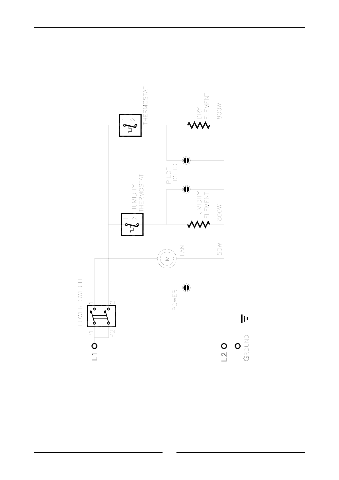
Circuit schematic
E85 Prover - Manual Fill
16
Page 19
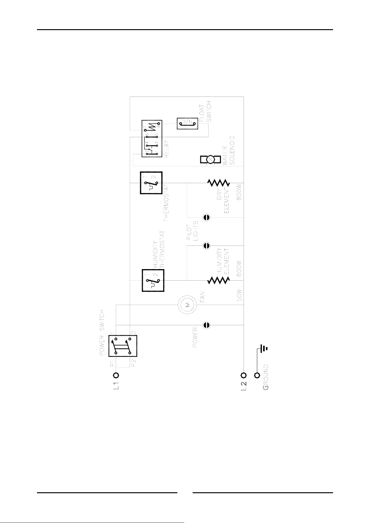
Circuit Schematic
E85A Prover - Auto Fill
17
Page 20

Page 21

 Loading...