

Page 1

®
Process Control and
Automation Solutions
from Elsag Bailey Group
®
Plant Loop to Plant Loop Remote Interface
(INPPR01)
E96-624
Page 2

WARNING notices as used in this instruction apply to hazards or unsafe practices that could result in
personal injury or death.
CAUTION notices apply to hazards or unsafe practices that could result in property damage.
NOTES highlight procedures and contain information that assists the operator in understanding the
information contained in this instruction.
WARNING
INSTRUCTION MANUALS
DO NOT INSTALL, MAINTAIN, OR OPERATE THIS EQ UIPMENT WITHOUT READING, UNDERSTANDING,
AND FOLLOWING THE PROPER
DAMAGE MAY RESULT.
Elsag Bailey
INSTRUCTIONS AND MANUALS; OTHER WISE, INJURY OR
RADIO FREQUENCY INTERFERENCE
MOST ELECTRONIC EQUIPMENT IS INFLUENCED BY RAD IO FREQUENCY INTERFERENCE (RFI). CAUTION SHOULD BE EXERCISED WITH REGARD TO THE USE OF PORTABLE COMMUNICATIONS EQUIPMENT IN THE AREA AROUND SUCH EQUIPMENT. PRUDENT PRACTICE DICTATES THAT SIGNS
SHOULD BE POSTED IN THE VICINITY OF THE EQUIPMENT CAUTIONING AGAINST THE USE OF PORTABLE COMMUNICATIONS EQUIPMENT.
POSSIBLE PROCESS UPSETS
MAINTENANCE MUST BE PERFORMED ONLY BY QUALIFIE D PER SONNEL AN D ONLY AFTE R SEC URING
EQUIPMENT CONTROLLED BY THIS PRODUCT. ADJUSTING OR REMOVING THIS PRODUCT WHILE IT IS
IN THE SYSTEM MAY UPSET THE PROCESS BEING CONTROLLED. SOME PROCESS UPSETS MAY
CAUSE INJURY OR DAMAGE .
AVERTISSEMENT
MANUELS D’OPÉRATION
NE PAS METTRE EN PLACE, RÉPARER OU FAIRE FONCTIONNER L’ÉQUIPEMENT SANS AVOIR LU,
COMPRIS ET SUIVI LES INSTRUCTIONS RÉGLEMENTAIRES DE
CET ÉGARD POURRAIT ÊTRE UNE C AUSE D’ACC IDENT OU DE DÉFAILL ANCE DU MA TÉRIEL.
Elsag Bailey
. TOUTE NÉGLIGENCE À
PERTURBATIONS PAR FRÉQUENCE RADIO
LA PLUPART DES ÉQUIPEMENTS ÉLECTRONIQUES SONT SENSIBLES AUX PERTURBATIONS PAR
FRÉQUENCE RADIO. DES PRÉCAUTIONS DEVR ONT ÊTRE PRISES LORS DE L’UTILISATION DU MATÉRIEL DE COMMUNICATION PORTATIF. LA PRUDENCE EXIGE QUE LES PRÉCAUTIONS À PRENDRE
DANS CE CAS SOIENT SIGNALÉES AU X ENDROITS VO ULUS DANS VOTR E USINE.
PERTURBATIONS DU PROCÉDÉ
L’ENTRETIEN DOIT ÊTRE ASSURÉ PAR UNE PERSONNE QUALIFIÉE EN CONSIDÉRANT L’ASPECT
SÉCURITAIRE DES ÉQUIPEMENTS CONTRÔLÉS PAR CE PRODUIT. L’AJUSTEMENT ET/OU L’EXTRACTION DE CE PRODUIT PEUT OCCAS IONNER DES À-COUPS AU PROCÉD É CONTRÔLE LORSQU’IL EST
INSÉRÉ DANS UNE SYSTÈME ACTIF. CES À-COUPS PEUVENT ÉGALEMENT OCCASIONNER DES
BLESSURES OU DES DOMMAGES M ATÉREILS.
NOTICE
The information contained in this docume nt is s ubj ect to change wi thout noti ce.
Elsag Bailey, i ts af fili at es , em pl oye es , an d a gen ts, a n d th e a u thor s an d co ntr ib utors to this publ ica ti on specif-
ically disclaim all liabilities and warranties, express and implied (including warranties of merchantability and
fitness for a pa rt icu lar p urp os e) , fo r the ac cur a cy, cur r en cy, co mple t en ess, an d/ o r r eliability of t he i nfo r mati on
contained herein and/or for the fitness for any particular use and/or for the performance of any material and/
or equipment selected in whole or part with the user of/or in reliance upon information contained herein.
Selection of materials and/or equipment is at the sole risk of the user of this publication.
This document contains proprietary i nformation of Elsag Baile y, Elsag Bailey Proces s Automation, and
is issued in strict confidence. Its use, or reproduc tion for use, for the re verse engineering, de velopment
or manufacture of hardware or software described herein is prohibited . No part of this docume nt may be
photocopied or reproduced without the prior written c onse nt of El sag B aile y.
Page 3

Preface
The Plant Loop to Plant Loop Remote Interface (INPPR01)
enables communication between a local and remote Plant
Loop. The interface consists of three modules, the Plant Loop
to Plant Loop Transfer Module (INPPT01), the Bus Transfer
Module (INBTM01) and the Loop Interface Module (INLIM03).
Plant Loop to Plant Loop Remote Interfaces connect through
cable, modem or microwave link.
This instruction explains PPR features, specifications, and
operation. It also includes installation and troubleshooting
procedures for the interface.
The system engineer or technician using the INPPR01 should
read and understand this instruction before installing the
interface modules. In addition, a complete understanding of
the INFI 90 system is beneficial to the user.
I-E96-624A
Page 4

List of Effective Pages
Total number of pages in this manual is 62, consisting of the following:
Page No. Change Date
Preface Original
List of Effective Pages Original
iii through viii Original
1-1 through 1-6 Original
2-1 through 2-4 Original
3-1 through 3-13 Original
4-1 through 4-10 Original
5-1 through 5-5 Original
6-1 Original
7-1 Original
8-1 Original
A-1 through A-5 Original
B-1 through B-2 Original
C-1 through C-4 Original
D-1 through D-2 Original
®
When an update is received, insert the latest changed pages and dispose of the superseded pages.
NOTE:
gin of the page adjacent to the changed area. A changed figure is indicated by a vertical bar in the
outer margin next to the figure caption. The date the update was prepared will appear beside the
page number.
On an update page, the changed text or table is indicated by a vertical bar in the outer mar-
I-E96-624A
Page 5

Safety Summary
GENERAL
WARNINGS
SPECIFIC
WARNINGS
SPECIFIC
CAUTIONS
Equipment Environment
All components, whether in transportation, operation or storage
must be in a noncorrosive environment.
Electrical Shock Hazard During Maintenance
Disconnect power or take precautions to ensure that contact with
energized parts is avoided when servicing.
Special Handling
This unit uses Electrostatic Sensitive Devices (ESD).
Disconnect power befo re installing dip shunts for slave mo dules on
the MMU backplane (sla ve expander bus). Failure to do so could
result in severe or fatal shock. (p. 3-10)
Ensure that the cable end marked J1 is connected to P1 on the
NICL01, and J2 is connected to the LIM. Failure to do so could
result in module damage (see Figure D-1). (p. D-1)
I-E96-624A vii
Page 6

Sommaire de Sécurité
®
AVERTISSEMENTS
D’ORDRE
GÉNÉRAL
AVERTISSEMENTS
D’ORDRE
SPÉCIFIQUE
ATTENTIONS
D’ORDRE
SPÉCIFIQUE
Envirmonent de l'dquipement
Ne pas soumettre le s comp osants a une atmo sphere corr osive lors
du transport, de l'entreposage ou de l'utilisation.
Rissques de chocs electriques lors de l'entretien
S'assurer de debranche r l'alimentation ou de prendre les precautions necessaires a eviter tout contact avec des composants sours
tension lors de l'enretien.
Precautions de manutention
Ce module contient des composantes sensibles aux decharges
electro-statiques.
Couper l'alimentation avant d'installer les dipshunts sur la plaque
arrlere du chassis de montage de modules (MMU). Toute negligence a cet egard constitue un risque de choc pouvant entrainer
des blessures graves, voire moretlles. (p. 3-10)
S'assuree que L'extremite ide ntifiee par J1 est reli ee a P1 du module NICL01 et que J2 est r eliee au modu le LIM. S inon, les mo dules
pouiraient etre endommages (voir la figure D-1). (p. D-1)
viii I-E96-624A
Page 7

Table of Contents
Page
SECTION 1 - INTRODUCTION....................................................................................................1-1
OVERVIEW ..................................................................................................................1-1
INTENDED USER.........................................................................................................1-1
HARDWARE DESCRIPTION..........................................................................................1-2
Plant Loop to Plant Loop Transfer Module (INPPT01) ..............................................1-2
Bus Transfer Module (INBTM01) ............................................................................1-2
Loop Interface Module (INLIM03)............................................................................1-2
Additional Hardware ..............................................................................................1-2
FEATURES...................................................................................................................1-2
INSTRUCTION CONTENT .............................................................................................1-3
HOW TO USE THIS MANUAL .......................................................................................1-3
GLOSSARY OF TERMS AND ABBREVIATIONS .............................................................1-4
REFERENCE DOCUMENTS..........................................................................................1-5
NOMENCLATURE ........................................................................................................1-5
SPECIFICATIONS.........................................................................................................1-6
SECTION 2 - DESCRIPTION AND OPERATION........................................................................2-1
INTRODUCTION...........................................................................................................2-1
LOCAL/REMOTE COMMUNICATIONS..........................................................................2-1
DATA INTEGRITY.........................................................................................................2-2
TIMING INTERVAL .......................................................................................................2-2
Transmit/Receive Timing .......................................................................................2-3
SECTION 3 - INSTALLATION .....................................................................................................3-1
INTRODUCTION...........................................................................................................3-1
SPECIAL HANDLING ....................................................................................................3-1
UNPACKING AND INSPECTION ....................................................................................3-1
INPPT01 SWITCH SETTINGS........................................................................................3-1
Option Switch (U72)...............................................................................................3-2
Serial Port Communication Rate (U73) ...................................................................3-3
Loop Address (U75)................................................................................................3-4
INLIM03 SWITCH SETTINGS........................................................................................3-5
INBTM01 SWITCH SETTINGS.......................................................................................3-7
TERMINATION UNIT (MODULE) CONFIGURATION .......................................................3-8
NTMF01/NIMF01/NIMF02 Configuration...............................................................3-8
One-way Control..............................................................................................3-8
Two-way Control............................................................................................3-10
NTCL01/NICL01 Configuration ............................................................................3-10
INSTALLING THE INTERFACE MODULES ..................................................................3-10
Installing the INPPT01 .........................................................................................3-10
Installing the INLIM03 and INBTM01 ...................................................................3-11
INSTALLING A REDUNDANT INTERFACE...................................................................3-12
INTERFACE CONFIGURATION ...................................................................................3-12
SECTION 4 - OPERATING PROCEDURES................................................................................4-1
INTRODUCTION...........................................................................................................4-1
PLANT LOOP TO PLANT LOOP TRANSFER MODULE LEDs AND CONTROLS ................4-1
Status LED ............................................................................................................4-2
CPU LEDs..............................................................................................................4-2
Memory LEDs ........................................................................................................4-2
I-E96-624A iii
Page 8

®
Table of Contents
SECTION 4 - OPERATING PROCEDURES
Stop Pushbutton ................................................................................................... 4-2
Reset Pushbutton.................................................................................................. 4-2
LOOP INTERFACE MODULE LEDs .............................................................................. 4-3
BUS TRANSFER MODULE LED ................................................................................... 4-3
MODES OF OPERATION .............................................................................................. 4-3
Configure Mode ..................................................................................................... 4-4
Execute Mode........................................................................................................ 4-4
Error Mode............................................................................................................ 4-5
One-Way Control................................................................................................... 4-5
Two-Way Control ................................................................................................... 4-6
REDUNDANT INTERFACE OPERATION ....................................................................... 4-6
INTERFACE POINT CAPACITY ..................................................................................... 4-7
MEMORY USAGE EXAMPLE........................................................................................ 4-8
Memory Usage in the Local PPT .............................................................................4-8
Memory Usage in the Remote PPT.......................................................................... 4-8
SECURITY FUNCTIONS ............................................................................................... 4-9
Hardware Checks .................................................................................................. 4-9
Software Checks.................................................................................................... 4-9
Utilities .................................................................................................................4-9
(continued)
Page
(continued)
SECTION 5 - TROUBLESHOOTING...........................................................................................5-1
INTRODUCTION .......................................................................................................... 5-1
Status Bytes.......................................................................................................... 5-2
SECTION 6 - MAINTENANCE.....................................................................................................6-1
INTRODUCTION .......................................................................................................... 6-1
MAINTENANCE SCHEDULE ........................................................................................6-1
SECTION 7 - REPAIR/REPLACEMENT PROCEDURES...........................................................7-1
INTRODUCTION .......................................................................................................... 7-1
MODULE REPAIR/REPLACEMENT.............................................................................. 7-1
SECTION 8 - SUPPORT SERVICES...........................................................................................8-1
INTRODUCTION .......................................................................................................... 8-1
REPLACEMENT PARTS AND ORDERING INFORMATION ............................................. 8-1
TRAINING.................................................................................................................... 8-1
TECHNICAL DOCUMENTATION................................................................................... 8-1
APPENDIX A - TERMINATION UNIT CONFIGURATION (NTMF01) ........................................ A-1
INTRODUCTION ..........................................................................................................A-1
APPENDIX B - TERMINATION UNIT CONFIGURATION (NTCL01)......................................... B-1
INTRODUCTION ..........................................................................................................B-1
APPENDIX C - TERMINATION MODULE CONFIGURATION (NIMF01/NIMF02) .................... C-1
INTRODUCTION ..........................................................................................................C-1
iv I-E96-624A
Page 9

Table of Contents
(continued)
Page
APPENDIX D - TERMINATION MODULE CONFIGURATION (NICL01)...................................D-1
INTRODUCTION..........................................................................................................D-1
List of Figures
No. Title Page
1-1. Diagram of Plant Loop to Plant Loop Remote Interfaces in Two-Way Control Mode ..1-1
2-1. Send/Receive Timing Diagram ...............................................................................2-4
3-1. Switch Locations on the PPT (CPU board) ...............................................................3-2
3-2. LIM Switch Locations.............................................................................................3-5
3-3. BTM Switch (SW1) Location ...................................................................................3-7
3-4. NTMF01 and NTCL01 in a Redundant Installation .................................................3-9
3-5. NIMF01/NIMF02 and NICL01 in a Redundant Installation .....................................3-9
3-6. Redundant Transceiver ........................................................................................3-13
4-1. PPT Faceplate LEDs ...............................................................................................4-1
4-2. LIM Faceplate LEDs ...............................................................................................4-3
4-3. BTM Faceplate LEDs..............................................................................................4-4
4-4. Local Plant Loop Using Bosth Serial Ports in One-Way Control ...............................4-5
4-5. Local and Remote Plant Loops in Two-Way Control ................................................4-6
4-6. PPT Utilities Menu ...............................................................................................4-10
A-1. Dipshunt Configuration for PPT Acting as DTE (Requires Modem or Other DCE) ... A-1
A-2. Dipshunt Configuration for Direct Connection with Local PPT Acting as DTE ........ A-2
A-3. Dipshunt Configuration for Direct Connection with Remote PPT Acting as DCE ..... A-3
A-4. Dispshunt Configuration for Diagnostic Terminal (Port 1 only) .............................. A-4
A-5. DB-25 Pin Assignments and RS-232-C Signals ..................................................... A-5
B-1. NTCL01 Termination Unit and Terminal Assignments ........................................... B-2
C-1. Dipshunt Configuration for PPT Acting as DTE (requires Modem or Other DCE) .... C-1
C-2. Dipshunt Configuration for Direct Connection of Local PPT Acting as DTE ............ C-2
C-3. Dipshunt Configuration for Direct Connection of Remote PPT Acting as DCE ........ C-3
C-4. Dispshunt Configuration for Diagnostic Terminal.................................................. C-4
D-1. Typical Twinax Cable Connection for the NICL01 .................................................. D-2
I-E96-624A v
Page 10

List of Tables
No. Title Page
3-1. Option Switch (U72) Settings ................................................................................ 3-2
3-2. Serial Port Communication Rate (U73)................................................................... 3-3
3-3. Message Throughput ............................................................................................. 3-4
3-4. U75 Loop Addresses ............................................................................................. 3-4
3-5. LIM Event Counter Addresses (SW1) ...................................................................... 3-5
3-6. LIM Error Counter Addresses (SW1) ...................................................................... 3-6
3-7. LIM Node Address Setting (SW2) ............................................................................ 3-7
3-8. BTM Options (SW1) ............................................................................................... 3-8
3-9. INPPR01 Function Codes..................................................................................... 3-13
4-1. PPT Status LED States ..........................................................................................4-2
4-2. BTM Status LEDs States ....................................................................................... 4-4
4-3. Memory Usage in Receiving Communication .......................................................... 4-7
4-4. Memory Usage in Sending Communication ............................................................ 4-8
5-1. PPT Error Codes .................................................................................................... 5-1
5-2. Status Bytes.......................................................................................................... 5-2
5-3. Status Byte Definitions.......................................................................................... 5-3
5-4. LIM Edge Connector P3 Pin Assignments ............................................................... 5-3
5-5. BTM Edge Connector P1 Pin Assignments.............................................................. 5-4
5-6. PPT CPU Board Edge Connector P2 Pin Assignments .............................................5-4
5-7. PPT CPU Board Edge Connector P3 Pin Assignments .............................................5-4
6-1. Maintenance Schedule........................................................................................... 6-1
B-1. NTCL01 Terminal Assignments..............................................................................B-1
B-2. BNC Terminal Assignments ...................................................................................B-1
B-3. Jumper Settings and Cable Types..........................................................................B-2
D-1. NICL01 Terminal Assignments...............................................................................D-1
D-2. BNC Assignments..................................................................................................D-1
D-3. Jumper Settings and Cable Types..........................................................................D-2
®
vi I-E96-624A
Page 11

OVERVIEW
INTENDED USER
SECTION 1 - INTRODUCTION
The Plant Loop to Plant Loop Remote Interface (INPPR01)
enables communication between a local and remote Plant
Loop. Two modes (user-selectable) of control are available. A
local Plant Loop is able to issue control commands and receive
Exception Report (XR) data from up to 32 remote Plant Loops
when it is in the one-way mode. Only the local Plant Loop can
initiate control commands and request exception reports in the
one-way mode. The two-way mode connects only two Plant
Loops. In the two-way mode, either Plant Loop is able to initiate
control commands and request exception reports. Plant Loop
to Plant Loop Remote Interfaces can connect through cable,
modem or microwave link. Figure 1-1 shows a block diagram of
Plant Loop to Plant Loop Remote Interfaces in two-way control.
The INPPR01 is a direct replacement of the Network 90 Plant
Loop to Plant Loop Gateway (NPPG02).
System engineers and technicians should read this manual
before installing and operating the INPPR01 module. Refer to
the Table of Contents to find specific information after the
module is operating.
INPPR01 INPPR01
LIM PPT
ICL IMFIMF ICL
LEGEND:
BTM = B US TRANSFER MODULE
IMF = MULTI-FUNCTION CONTROLLER TERMINATION MOD U L E
ICL = COMM U N IC ATION TERMINATION M OD ULE
LIM = LOOP INTERFACE MO D U L E
PPT = PLANT LOOP TO PLANTLOOP T RANSFER MODULE
BTM BTMPPT LIM
DMA
CABLE
MODULE BUS MODULE BUS
PLANT LOOP PLANT LOOP
DMA
CABLE
Figure 1-1. Diagram of Plant Loop to Plant Loop Remote Interfaces in
Two-Way Control Mode
T00417A
OVERVIEW
I-E96-624A 1 - 1
Page 12

INTRODUCTION
HARDWARE DESCRIPTION
The Plant Loop to Plant Loop Remote Interface acts as another
node on the Plant Loop. The interface consists of three modules
on a dedicated module bus.
Plant Loop to Plant Loop Transfer Module (INPPT01)
This module processes incoming and outgoing Plant Loop messages, buffers data and communicates with other PPT modules
in remote Plant Loops. The PPT is a double circuit board module. It has a memory board and CPU board. The user selects
general operating characteristics and point definitions through
software configuration. Other characteristics such as type of
control (one-way or two-way), Node ID and port options are
user-configured through dipswitches on the CPU board.
Bus Transfer Module (INBTM01)
The BTM is responsible for translating messages from the LIM
and placing them on the module bus. It also receives messages
from the PPT. It translates those messages and sends them to
the LIM through a direct memory access (DMA) cable.
®
Loop Interface Module (INLIM03)
The LIM provides the communication link between the Plant
Loop and the PPT. It receives messages from Plant Loop nodes
and monitors loop status. The LIM forwards messages from the
loop to the PPT (though the BTM) via a direct memory access
(DMA) cable. Additionally, it receives messages from the PPT
(through the BTM) and sends them to the proper node on the
loop.
Additional Hardware
Some applications require additional hardware such as a
modem network, radio link or microwave link. This hardware is
not part of the INPPR01 standard hardware. INFI 90 Digital
Slave Modules (IMDSO01 through IMDSO04, IMDSM05) support control signals to these devices.
FEATURES
The Plant Loop to Plant Loop Remote Interface provides communication between a local loop and one or more remote loops.
This interface has user selectable control modes. Selecting the
one-way mode enables a local loop to receive exception reports
from up to 32 remote loops. In the one-way mode, only the
local loop can initiate control commands. The two-way mode
enables bidirectional control and exception reporting between
HARDWARE DESCRIPTION
1 - 2 I-E96-624A
Page 13

INSTRUCTION CONTENT
INTRODUCTION
a local and one remote loop. This interface handles a maximum
capacity of 5,000 blocks of exception report data.
The INPPR01 can handle a mixture of point types. Point types
include analog and digital station, remote control memory,
manual set constant and device driver. The user can select the
interface communication rate, up to 19.2 kbaud.
This document is divided into eight sections. Introduction
provides an overview of the individual modules of the PPR, a
list of related documents, glossary of terms and abbreviations
and specifications. Description and Operation explains how
PPR communication occurs. Installation covers preliminary
module setup, physical installation and configuration. Operat-
ing Procedures explains faceplate LEDs, controls and inter-
face operating modes. Troubleshooting explains how to
troubleshoot problems with the interface modules using error
codes and status byte information and lists the corrective
action. Maintenance contains a maintenance schedule for the
slave module. Repair/Replacement Procedures explain how
to replace the PPR modules. Support Services explains the
customer training Bailey Controls Company provides and
information about ordering replacement parts.
HOW TO USE THIS MANUAL
Read this manual in sequence. It is important to become familiar with the entire contents of this manual before using the
PPR. The organization of this manual enables the user to find
needed information quickly.
1. Read and do the steps in Section 3.
2. Read Section 4 thoroughly before powering up the station.
3. Refer to Section 5 if a problem occurs.
4. Refer to Section 6 for scheduled maintenance
requirements.
5. Use the Section 8 for a list of replacement parts and warranty information.
INSTRUCTION CONTENT
I-E96-624A 1 - 3
Page 14

INTRODUCTION
GLOSSARY OF TERMS AND ABBREVIATIONS
Term Definition
DCE
DTE
Dipshunt
EWS
Module Bus
Node
OIS
PCI
PCU
Plant Loop
RS-232-C
Slave Expander
Bus
XR
Data Circuit-Terminat ing Equipment - The term ination point of a communication circuit such as a line driver or modem.
Data Terminal Equipment - End-user machine of a communication circuit such as a
terminal or computer.
A dual in-line package with shorting bars.
Engineering Work Station - An integrated hardware and software personal computer
system for configuring and monitoring INFI 90/Network 90 modules.
The serial communication link between a process control module and other process
control modules.
Device(s) on the INFI 90/Network 90 Plant Loop, Superloop or INFI-NET (maximum
of 63 on Plant Loop, 250 on Superloop/INFI-NET). A node can be an Operator Interface Station (OIS), a Process Control Unit (PCU) or Engine ering Work Station (EW S)
in any combination.
Operator Interface Station - Integrated operator console with data acquisition and
reporting capabilities. It provides a window into the process for flexible control and
monitoring.
Plant Loop to Computer Interface (INPCI01/02) - A Plant Loop communication interface that provides configuration and control of the Plant Loop through a host
computer.
Process Control Unit - Rack type industrial cabinet that contains master, slave and
communication modules and their communication paths.
INFI 90 data communication highway with 63 node capacity.
One in a series of standards developed b y the Ele ctro nic s In dus try As so cia tio n (EIA)
that specifies what signals and volt ag es wil l b e used to transmit data from D TE (computer) to DCE (modem).
Parallel address/data bus between the master module and the slave.
Exception Report - A function block that reports a monitored point value when that
value changes and is polled by a communication or master module.
®
GLOSSARY OF TERMS AND ABBREVIATIONS
1 - 4 I-E96-624A
Page 15

REFERENCE DOCUMENTS
INTRODUCTION
The following documents provide additional information about
INPPR01 support hardware and software. Please refer to them
as needed.
Document Number Document
I-E96-309 Digital Slave Module (I MDSM05)
I-E96-310 Digital Slave Output Module (IMDSO01/02/03)
I-E96-313 Digital Slave Output Module (IMDSO04)
I-E93-905-2 Enhanced CIU Programmer's Reference Manual
I-E93-900-20 Function Code Application Manual
I-E96-611 Loop Interface/Bus Interface Module
(INLIM03/INBIM02)
I-E96-110 Operator Interface Station
I-E96-620 Plant Loop to Computer Interface (INPCI01)
I-E96-621 Plant Loop to Computer Interface (INPCI02)
I-E93-900-5 Site, Planning and Equipment Installation
I-E93-911 Termination Unit Manual
NOMENCLATURE
Hardware Nomenclature
Field Termination Panel NFTP01
Module Mounting Unit IEMMU01/02
Multi-Function Controller Termi nation Module
Redundant Termination Module
Cable
Multi-Funct ion Controller Termination Unit
Cable
Communication Termination Module
Cable
Communication Termination Unit
Cable
Termination Mounting Unit NTMU01/02
NIMF01
NIMF02
NKTM01
NTMF01
NKTU01
NICL01
NKLS04
NTCL01
NKLS03
REFERENCE DOCUMENTS
I-E96-624A 1 - 5
Page 16

INTRODUCTION
SPECIFICATIONS
Memory
PPT
®
256 kbytes UVROM
512 kbytes RAM
80 kbytes NVM (non-volatile memory)
LIM
BTM
I/O Ports
Communication Rates
Power Requirements
PPT
LIM
BTM
Environmental
Electromagnetic/Radio
Frequency Interference
Ambient Temperature
Relative Humidity
Altitude
2 kbytes RAM
4 kbytes ROM
32 kbytes RAM
16 kbytes ROM
2 RS-232C serial ports
50 to 19,200 baud (user selectable)
6 amps @ +5 VDC; 30 watts
37 mA @ +15 VDC; 0.55 watts
18 mA @ -15 VDC; 0.27 watts
+5 VDC @ 2.0 amps; 10 watts nominal
15 VDC @ 80 mA; 1.2 watts nominal
±
+5 VDC @ 1.0 amps; 5 watts nominal
+15 VDC @ 150 mA; 2.25 watts nominal
-15 VDC @ 120 mA; 1.80 watts nominal
Values are not avail able a t th is time. Keep cabi net doo rs clo sed. Do no t use co mmunication equipment any closer than two meters from the cabinet.
o
to 70oC (32o to 158oF)
0
0 to 95% up to 55
0 to 45% at 70
o
C (131oF) (non-condensing)
o
C (158oF) (non-condensing)
Sea level to 3 Km (1.86 miles)
Air Quality
Certification
Noncorrosive
All INPPR01 modules have been individually CSA certified for use as process
control equipment in an ordinary (nonhazardous) environment.
Specifications Subject To Change Without Notice
SPECIFICATIONS
1 - 6 I-E96-624A
Page 17

SECTION 2 - DESCRIPTION AND OPERATION
INTRODUCTION
This section explains the operation of the Plant Loop to Plant
Loop Remote Interface.
LOCAL/REMOTE COMMUNICATIONS
Local and remote PPTs communicate with each other through
a series of commands and replies over the serial ports. In the
one-way mode, the local PPT issues commands only; in
two-way, both the local and remote PPTs issue commands. The
command format is:
12345
Loop
Number
where:
Message
Byte Count
Command
Code
Command
Data
Checksum or
CRC
1. Loop number is the loop that responds to the command (1
byte field).
2. Message byte count is the total length of the message (2
byte field).
3. Command code is the command code the PPT processes (1
byte field).
4. Command data is the specific command (variable length
field).
5. Checksum is the sum of all the bytes in the command (1
byte field) or CRC, the cyclic redundancy check word computed
for all of the bytes in the command using the CRC-16 algorithm (2 byte field).
All communications between interfaces use this format.
INPPR01 commands are a modified form of Plant Loop to Computer Interface commands (refer to I-E93-905-9 for command
details). The PPT format eliminates the key field from the PCI
command. In addition to PCI commands, the PPT processes a
command (code 29) that permits passage of a required PPT
message.
INTRODUCTION
I-E96-624A 2 - 1
Page 18

DESCRIPTION AND OPERATION
DATA INTEGRITY
Verification of data integrity consists of even parity checking
and the checksum in each command and reply format. The
interface retries a transaction whenever it detects a communication error.
There are two levels of communication breakdown detection.
The first level detects a complete failure of the communication
link. Should this occur, Function Code 130 output block one
will be set (logic one) and the alarm status bit set if port 1 fails.
If port 0 fails, the output of block two will be set (logic one) and
the alarm status bit set.
The second level of communication failure concerns the loss of
a single remote interface. If this occurs, all blocks coming from
that remote interface are bad quality. The PPR makes use of a
user-configurable watchdog timer or absolute retry count in
determining the sensitivity to these failures (refer to
I-E93-200-20 for information about Function Code 130, S10
and S12).
®
TIMING INTERVAL
The local interface attempts communication twice a second
with all the remote interfaces. Each successful transaction
resets the communication watchdog timer. Therefore, if the
communication link is faulty, no transactions occur successfully. After the watchdog time period expires, the link is
marked bad.
For all communication transactions, the watchdog timer is
reset on the reception of each character. If the time interval
between characters in a transaction exceeds 1.25 seconds, the
transaction is flushed and the remote interface is marked as
being suspect. This condition causes retry logic to begin. Retry
logic consists of retrying communication once per second for a
number of times equal to one-fourth the watchdog time period
if the absolute retry count is set to zero. A non-zero absolute
retry count causes a specific number of retries (the number of
the retry count). If the failure persists after the retry period
expires, the remote interface is internally marked off-line and
the quality of all the points it provides are marked bad.
Thereafter, a single retry of the failed remote interface occurs
at a period equal to one half the watchdog timer period until a
successful transaction occurs. The local interface sets the
quality of all the points to their original state (before the communication failure). It also does a one time poll of the current
value of each point.
A user-configurable time delay envelopes each command/reply
sequence. This time delay accommodates the keying up/down
DATA INTEGRITY
2 - 2 I-E96-624A
Page 19

Transmit/Receive Timing
DESCRIPTION AND OPERATION
of modems and transmission equipment. The interface coordinates this activity through the RTS (Request-To-Send) signal of
the RS-232-C port for modems or through digital outputs when
using Digital Slave Modules (IMDSM05, IMDSO01/02/03/04)
to enable other transmission equipment.
The user can set up the RS-232-C ports to operate as Data Circuit-Terminating Equipment (DCE) or Data Terminal Equipment (DTE). In the DCE mode, the Request-To-Send (RTS) line
is always asserted. In the DTE mode, the RTS line is asserted
before data transmission and inhibited after data transmission
occurs.
The following events occur (see Figure 2-1) on port 0 when
transmitting a command:
1. Assert RTS on the RS-232-C port (DTE mode) or set digital
outputs 1 and 4 on the digital slave module.
2. A delay occurs between the time the port 0 asserts the RTS
(or the digital outputs are set) and the command transmission
occurs. Function Code 130 (S5) sets this delay (in
milliseconds).
3. Output 4 is reset.
4. A delay occurs between the time output 4 is reset and output 1 is reset. Function Code 130 (S6) sets the length of this
delay.
5. Output 1 is reset and RS-232-C RTS signal is inhibited
(DTE mode).
6. A delay set by S5 of Function Code 130 occur between the
output 1 reset and the reception of the reply.
7. The remote target issues a reply.
The following events occur (see Figure 2-1) when Port 0
receives a command:
1. The port receives the command.
2. A time delay set by S6 of Function Code 130 occurs.
3. The RS-232-C asserts the RTS signal (DTE mode) or set
outputs 1 and 4 on the digital slave modules.
4. A time delay set by S5 of Function Code 130 occurs.
TIMING INTERVAL
I-E96-624A 2 - 3
Page 20

DESCRIPTION AND OPERATION
5. The remote interface transmits a reply to the interface
sending the command.
6. Output 4 is reset.
7. A time delay set by S6 of Function Code 130 occurs.
8. Output 1 resets, RS-232-C RTS signal is inhibited (DTE
mode).
®
S5
DELAYS5DELAY
0
RTSASSERTED (DTE MODE)
SET OUT1 A ND OUT4
0
S7
DELAY
0
RTSASSERTED (DTE MODE)
SET OUT2 A ND OUT5
TRANSMIT
COMMAND
TxTxTxTxTxTx
RESET OUT4 RTS INHIBITED (DTE MOD E)
RECEIVE
COMMAND
RxRxRxRxRxRx
TRANSMIT
COMMAND
TxTxTxTxTxTx
RESET OUT5 RTS INHIBITED (DTE MOD E)
NOTE:
RTS assert and inhibit apply to DTE mode only. RTS is
always asserted for DCE mode.
SENDING A COM MAND, PORT 0 (P0)
S6
DELAY
RESET OUT1
RECEIVING A REPLY, PORT 0 (P0)
S6
DELAY
RTSASSERTED (DTE MODE)
SET OUT1 AND OUT4
SENDING A COM MAND, PORT 1 (P1)
S8
DELAY
RESET OUT2
S5
DELAY
S5
DELAY
S7
DELAY
RECEIVE
RxRxRxRxRxRx
TRANSMIT
TxTxTxTxT xTx
RECEIVE
RxRxRxRxRxRx
S6
REPLY
REPLY
RESET OUT4 RTSINH IBITED (DTE MODE)
REPLY
DELAY
S6
DELAY
RESET OUT1
S8
DELAY
TIME
TIME
TIME
RECEIVING A REPLY, PORT 1 (P1)
RECEIVE
COMMAND
0
RxRxRxRxRxRx
S8
DELAY
RTSASSERTED (DTE MODE)
SET OUT2 AND OUT5
S7
DELAY
TRANSMIT
REPLY
TxTxTxTxT xTx
S8
DELAY
TIME
RESET OUT5 RTSINH IBITED (DTE MODE)
RESET OUT2
T00418A
Figure 2-1. Send/Receive Timing Diagram
TIMING INTERVAL
2 - 4 I-E96-624A
Page 21

INTRODUCTION
SPECIAL HANDLING
SECTION 3 - INSTALLATION
This section explains special handling procedures, switch settings for each interface module, and how to install related
hardware. Complete the preliminary procedures in this section
before placing the INPPR01 into operation.
Plant Loop to Plant Loop Interface modules use Electrostatic
Sensitive (ESD) devices. Follow these handling procedures:
1. Keep the modules in their special anti-static bags until you
are ready to install them in the system. Save the bags for
future use.
2. Ground the anti-static bag before opening.
3. Verify that all devices connected to the modules are properly grounded before using them.
4. Avoid touching the circuitry when handling the module.
UNPACKING AND INSPECTION
1. Examine the PPT, LIM and BTM immediately to verify that
they have not been damaged in transit.
2. Notify the nearest Bailey Controls Sales Office of any such
damage.
3. File a claim for any damage with the transportation company that handled the shipment.
NOTE:
when working with interface modules. This kit connects the static
dissipative work surface and technician to the same ground point.
Always use the Bailey Field Static Kit (P/N 1948385A1)
4. Use the original packing material and/or container to store
the modules.
5. Store the module in an environment of good air quality and
free from temperature and moisture extremes.
INPPT01 SWITCH SETTINGS
The INPPT01 consists of two circuit boards, a memory board
and a CPU board. The memory board has no user-configurable
INTRODUCTION
I-E96-624A 3 - 1
Page 22

INSTALLATION
®
operating options. The CPU board has three dipswitches that
set the module operating characteristics. These switches provide the means of establishing the type of control, serial port
communication rate, and loop address. Figure 3-1 shows the
dipswitch locations on the CPU board.
JUMPER S
J1, J2, J3
STOPSW2
RESET SW1
Option Switch (U72)
J1 J2 J3
U72 U73 U75
1234
5678 1234
OPEN
OPTION
SWITCH
5678 1234
OPEN
BAUD RATE
SWITCH
5
OPEN
DIAGNOSTICS
SWITCH
Figure 3-1. Switch Locations on the PPT (CPU board)
U72 is an eight position dipswitch that determines the operating options of the module. Table 3-1 lists the U72 option settings. Record the U72 settings in the space provided. When
setting switches, 0 = Closed (on) and 1 = Open (off).
P1
P3
P2
T00387A
Table 3-1. Option Switch (U72) Settings
Position Setting Function
10
1
20
1
30
1
40
1
50
1
60
1
ROM checksumming enabled
ROM checksumming disabled
RS-232-C port in DCE mode (direct connecti ons )
RS-232-C port in DTE mode (modem connections)
Equipment select output de-energized
Equipment select output energized
Port 1 option interface communication
Port 1 utility option
Interface ID local
2
3
Interface ID remote
Interface mode two-way control
4
Interface mode one-way control
1
User
Setting
INPPT01 SWITCH SETTINGS
3 - 2 I-E96-624A
Page 23

INSTALLATION
Table 3-1. Option Switch (U72) Settings
Position Setting Function
70
1
80
1
0 = Closed (on), 1 = Open (off)
NOTES:
1. A unique equipment select output can exist between the primary and secondary PPT. The equipment select output is digital output three
of a digital slave (IMDSM05 or IMDSO01/02/03/04).
2. Port 1 responds as DCE when it is configured as a utility port. Set switch position 4 = 1 if port 1 is not used as a communication interface.
3. Define only one interface as a local interface (position 5).
4. The following conditions apply when using two-way control (position 6 = 0):
a. The port 1 option defaults to interface communication (position 4 = 0).
b. The local INPPR01 uses port 0 as its command port and port 1 as its reply port.
c. The remote INPPR01 uses port 1 as its command port and port 0 as its reply port.
d. Both the local and remote interface must have a loop address of 0 (U75).
Don not initialize NVM
Initialize NVM
Primary/Secondary (one module of redundant pair is set to 0,
the other module is set to 1)
(continued)
User
Setting
Serial Port Communication Rate (U73)
U73 is an eight pole dipswitch that sets the serial port communication rate. The communication rate directly affects data
throughput. Refer to Table 3-2 for communication rates. Table
3-3 lists message throughput for different point types. Record
the U73 setting in the space provided.
Table 3-2. Serial Port Communication Rate (U73)
Switch Position
Port 0
1234
Port 1
5678
0000 0000 50
1000 1000 75
0100 0100 110
1100 1100 134.5
0010 0010 150
1010 1010 300
0110 0110 600
1110 1110 1200
0001 0001 1800
1001 1001 2000
0101 0101 2400
1101 1101 3600
0011 0011 4800
1011 1011 7200
0111 0111 9600
1111 1111 19200
: 0 = Closed (on), 1 = Open (off)
NOTE
Baud Rate
User Setting
Port 0
1234
Port 1
5678
INPPT01 SWITCH SETTINGS
I-E96-624A 3 - 3
Page 24

INSTALLATION
®
Table 3-3. Message Throughput
Loop Address (U75)
Point Type
Number of
Bytes
Time per
1
Point
Points per
Second
Station 19 10.4 msec 96
Analog 8 4.7 msec 214
Digital 5 3.1 msec 322
Remote Control Mem-
7 4.1 msec 241
ory (RCM)
Remote Manual Set
7 4.1 msec 241
Constant (RMSC)
Device Driver 7 4.1 msec 241
1. These figures are based on the calculated throughput of the various Exception Report data types
(at 19200 baud). Regard less of commun ication rat e, the software overhead is app roximatel y 0.5
millisecond per point.
Dipswitch U75 sets the loop address. Valid addresses are 0
through 31. Table 3-4 shows examples of switch settings for
the loop address. Record the loop address in the space
provided.
Table 3-4. U75 Loop Addresses
Example Settings
Address
Example
Switch Position 12345
Binary Value 168421
0 00000
9 01001
26 11010
User Setting
User
Address
0 = Closed (on), 1 = Open (off)
NOTE:
Switch Position 12345
Binary Value 168421
INPPT01 SWITCH SETTINGS
3 - 4 I-E96-624A
Page 25

INLIM03 SWITCH SETTINGS
The Loop Interface Module (INLIM03), shown in Figure 3-2, has
two user-configurable dipswitches: Event/Error Counter
Address Switch SW1 and Address Switch SW2. Tables 3-5 and
3-6 list the switch settings for the Event and Error Counters.
The LIM faceplate LEDs display the contents of the event/error
counters. Switch SW2 poles 1 and 2 are CLOSED for normal
operation. Refer to Table 3-7 for SW2 settings. The LIM can
have any address from 1 to 63.
XU4
S1
EVENT/ERROR
COUNTER ADDRESS
1234
5678
OPEN
1234
5678
OPEN
INSTALLATION
P1
EDGE
CONNECTORS
P3
P2
P4 CONNECTOR
RIBBON CABLE
ATTACHES HERE
S2
NODE ADDRESS
Figure 3-2. LIM Switch Locations
Table 3-5. LIM Event Counter Addresses (SW1)
Counter
Address
48 30 00110000 Total messages transmitted, including
49 31 00110001 Transmit retries.
50 32 00110010 Composite BTM Receive/Transmit, 4 bits
51 33 00110011 Messages taken from the BTM transmit
52 34 00110100 Messages stored in BTM receive buffer.
53 35 00110101 Interrupt Requests (IRQs) sent by BTM.
54 36 00110110 High Priority (HP) messages transmitted.
55 37 00110111 High Priority messages received.
56 38 00111000 Commands issued by the BTM.
57 39 00111001 Missed BTM transmit requests.
Hex
Address
Switch Position
12345678
Description
forwarding.
each. Receive is viewed at the top LED.
buffer.
T00403A
User
Setting
INLIM03 SWITCH SETTINGS
I-E96-624A 3 - 5
Page 26

INSTALLATION
®
Counter
Address
Hex
Address
Table 3-5. LIM Event Counter Addresses (SW1)
Switch Position
12345678
Description
(continued)
58 3A 00111010 Spurious Non-Maskable Interrupts (NMI)
caused by address present.
59 3B 00111011 HEY (request for an interrupt; generated
by BTM) message sent.
60 3C 00111100 Messages discarded when the destination
is off-line.
61 3D 00111101 HEY time expirations.
62 3E 00111110 Passes through the IDLE level
(2 bytes wide).
0 = Closed (on), 1 = Open (off)
NOTE:
Table 3-6. LIM Error Counter Addresses (SW1)
Counter
Address
64 40 01000000 Composite error count developed every
65 41 01000001 Unresolved NMI interrupts.
66 42 01000010 Unresolved IRQ interrupts.
67 43 01000011 Unresolved timer interrupts.
68 44 01000100 Unused.
69 45 01000101 Queue overflows.
70 46 01000110 Unresolved BTM IRQs.
71 47 01000111 Sequence errors.
72 48 01001000 Header CRC/OVRN errors.
73 49 01001001 Data CRC/OVRN errors.
74 4A 01001010 Messages developing data CRC errors on
75 4B 01001011 Transmission failures.
76 4C 01001100 Watchdog timer expirations.
77 4D 01001101 Data length errors.
78 4E 01001110 Loop - 1 Receive (RCV) failure.
79 4F 01001111 Loop - 2 Receive failures.
80 50 01010000 Loop - 1 Transmit (TX) failure.
81 51 01010001 Loop - 2 Transmit failures.
0 = Closed (on), 1 = Open (off)
NOTE:
Hex
Address
Switch Position
12345678
Description
handshake period - the summation of all
other error counters.
route to destination.
User
Setting
User
Setting
INLIM03 SWITCH SETTINGS
3 - 6 I-E96-624A
Page 27

1 0 0000001
T00401A
RESET
SWITCH
SW1
OPTION SWITCH
EDGE
CONNECTORS
P3
P2
P1
5
1
OPEN
9 0 0001001
63 0 0111111
NOTE: 0 = Closed (on), 1 = Open (off)
INBTM01 SWITCH SETTINGS
Address
Example
User
Address
INSTALLATION
Table 3-7. LIM Node Address Setting (SW2)
Example Settings
Switch Position 1 2345678
Binary Value 1286432168421
User Setting
Switch Position 1 2345678
Binary Value 1286432168421
The Bus Transfer Module (INBTM01), shown in Figure 3-3, has
one user-configured dipswitch (SW1). SW1 enables module
diagnostics. Refer to Table 3-8 and set SW1 for normal
operation.
Figure 3-3. BTM Switch (SW1) Location
INBTM01 SWITCH SETTINGS
I-E96-624A 3 - 7
Page 28

INSTALLATION
®
Table 3-8. BTM Options (SW1)
Switch Position
12345
00000 Normal operation.
00010 Normal BTM operation without catastrophic error checking (for Test Pur-
poses ONLY).
00100 RAM test mode. If Status LED turns red, the module has failed the test.
00110 ROM test mode. If Status LED turns red, the module has failed the test.
01000 Execute Interrupt Request (IRQ) LIM handshake diagnostic. Used in
combination with the LIM off-line diagnostics.
NOTE: 0 = Closed (on), 1 = Open (off)
Function User Setting
TERMINATION UNIT (MODULE) CONFIGURATION
Two of the interface modules (INLIM03, INPPT01) require termination. The INPPT01 terminates with the NTMF01 or
NIMF01/NIMF02. The INLIM03 terminates with the NTCL01 or
NICL01. Appendices A through D contain disphunt configuration information. Figure 3-4 shows a diagram of the NTMF01
and NTCL01 in a redundant installation. Figure 3-5 shows a
diagram of the NIMF01/NIMF02 and NICL01 in a redundant
installation.
NTMF01/NIMF01/NIMF02 Configuration
The TMF and IMF provide the INPPT01 with two RS-232-C
ports. Configure these ports to operate as DTE, DCE or diagnostic terminal. Refer to Figures A-1, A-2, and A-3 for NTMF01
dipshunt configurations. Refer to Figures C-1, C-2, and C-3 for
NIMF01/NIMF02 dipshunt configurations.
NOTE:
tion modules to terminate a redundant interface. Non-redundant
interfaces need only the NIMF01.
You must use the NIMF01 and NIMF02 whe n usi ng term in a-
ONE-WAY CONTROL
Configure port 0 on the local and remote interfaces to act as
DTE. One local INPPR01 can communicate with up to 32
remote interfaces in the one-way control mode. Additional
communication equipment such as a modem network, radio
link or microwave link is required when interfacing multiple
remotes. The user supplies any additional equipment that is
needed.
TERMINATION UNIT (MODULE) CONFIGURATION
3 - 8 I-E96-624A
Page 29

COMMUNICATION HIGHWAY(PLANT LOOP)
INSTALLATION
TWINAX
OR COA X
TWINAX
OR COA X
SLAVE EXPANDER BUS
NTCL01
P1 P1
NKLS03
P3
DMA
CABLE
MODULE BUS
INBTM01INLIM03 INLIM 03INPPT01
P3 P3
P1 P3
INPPT01
NKTU01NKTU01
MODULE BUS
NKLS03
INBTM01 INLIM03
DMA
CABLE
NTMF01
TERMINATION UNIT
COMMUNICATIONS
PORT 0
PORT 1
COMMUNICATIONS
OR UTILITY
TO OTHER PPR
Figure 3-4. NTMF01 and NTCL01 in a Redundant Installation
NTCL01
P3
T00419A
COMMUNICATION HIGHWAY(PLANT LOOP)
TWINAX
OR COA X
SLAVE EXPANDER BUS
NICL01
P1
P3
NKLS04
DMA
CABLE
MODULE BUS
INBTM01INLIM03 INLIM 03INPPT01
P3 P3
P1
NIMF01
TERMINATION
MODULE
J2 J3
COMMUNICATIONS
PORT 0
MODULE BUS
INPPT01
NKTM01NKTM01
P1
NIMF02
TERMINATION
MODULE
INBTM01 INLIM03
PORT 1
COMMUNICATIONS
OR UTILITY
TO OTHER PPR
Figure 3-5. NIMF01/NIMF02 and NICL01 in a Redundant Installation
DMA
CABLE
TWINAX
OR COA X
NKLS04
NICL01
P1
P3
T00420A
TERMINATION UNIT (MODULE) CONFIGURATION
I-E96-624A 3 - 9
Page 30

INSTALLATION
®
When directly connecting only one remote interface in one-way
control, set port 0 on the local interface to act as a DTE. Set
port 0 on the remote interface to act as DCE.
TWO-WAY CONTROL
The interface requires both serial communication ports in the
two-way control mode. Connect port 0 of the local Plant Loop to
port 0 of the remote Plant Loop. Connect port 1 of local Plant
Loop to port 1 of the remote Plant Loop.
Configure the termination unit to act as DTE to enable the
Plant Loop to Plant Loop Transfer Module to communicate with
DCE (i.e, a modem). Configure the termination unit to act as
DCE to enable the PPT to communicate with DTE (i.e., a terminal). Figure A-4 shows how the termination dipshunt configuration directs the RS-232-C signals.
NTCL01/NICL01 Configuration
The TCL and ICL provide the INLIM03 with Plant Loop termination. The user has the option of using Twinax or Coax cable to
connect the interface to the Plant Loop. Tables B-3 (NTCL01)
and D-3 (NICL01) show the jumper settings for twinax and
coax cables. Set the jumpers accordingly for your application.
NOTE:
interface communication port. The PPT option switch (U72) position
4 must be set to 0 (utility option). Port 1 will always act as a DCE in
this configuration.
Always configure port 1 as a utility port if it is not used as an
NOTE:
to the
For complete cable and TU/TM installation information, refer
Termination Unit Manual
l (
I-E93-911
).
INSTALLING THE INTERFACE MODULES
If the switch settings on the interface modules are complete,
they are ready to be installed in the Module Mounting Unit
(MMU).
Installing the INPPT01
WARNING Disconnect power before installing dipshunts for slave mod-
ules on the MMU backplane (slave expander bus). Failure to do
so could result in severe or fatal shock.
AVERTISSEMENT Couper l'alimentation avant d'installer les dipshunts sur la
plaque arrlere du chassis de montage de modules (MMU).
Toute negligence a cet egard constitue un risque de choc pouvant entrainer des blessures graves, voire moretlles.
INSTALLING THE INTERFACE MODULES
3 - 10 I-E96-624A
Page 31

INSTALLATION
To install the PPT:
1. Verify the PPT slot assignment in the MMU.
a. If you are installing redundant PPTs, install a 24 pin
disphunt in the Slave Expander Bus socket between the
slot used by the primary PPT and the slot used by the secondary PPT. Both PPTs must reside on the same Slave
Expander Bus.
b. Each PPT must reside on its own module bus.
2. Attach the hooded end of the cable (NTKU01 for the
NTMF01; NKTM01 for the NIMF01 and NIMF02) to the MMU
backplane cable connector opening for the PPT. The other end
of the cable attaches to the termination unit or backplane of
the Termination Mounting Unit (NTMU01).
3. Guide the top and bottom edges of the circuit card along
the top and bottom rails of MMU.
4. Slide the module into the slot; push the module until the
front panel is flush with the top and bottom of the MMU frame.
5. Turn the two captive latches a half turn to lock the module
in place.
Installing the INLIM03 and INBTM01
The LIM and BTM should be installed as a pair in adjacent
slots. To install the LIM/BTM:
1. Verify the MMU slot assignments for the modules. If you
are installing redundant LIM/BTM pairs, each BTM must be
installed on the module bus that belongs to its related PPT.
2. Attach the hooded end of the cable (NKLS03 for NTCL01;
NKLS04 for the NICL01) to the MMU backplane cable connector opening for the LIM. The other end of the cable attaches to
the termination unit or TMU backplane.
3. Connect one end of the Bailey supplied ribbon cable (DMA
cable) to the P4 connector on the LIM. Connect the other end of
the DMA cable to the P4 connector on the BTM (see Figures 3-2
and 3-3).
4. Guide the top and bottom edges of both circuit cards along
the top and bottom rails of adjacent slots in the MMU.
5. Slide the modules into the slot; push the module until the
front panels are flush with the top and bottom of the MMU
frame.
INSTALLING THE INTERFACE MODULES
I-E96-624A 3 - 11
Page 32

INSTALLATION
6. Turn the two captive latches a half turn to lock the module
in place.
INSTALLING A REDUNDANT INTERFACE
Installing a redundant interface requires an additional set of
INPPT01, INLIM03 and INBTM01 modules. Both PPT modules
must be on the same Slave Expander Bus, but reside on separate Module Bus. Each PPT has a pair of LIM/BTM modules on
a dedicated Module Bus.
Observe the following conditions when installing a redundant
interface:
1. U72 position 8 must be set to 0 on the primary PPT.
2. U72 position 8 must be set to 1 on the secondary PPT.
3. SW1 all positions must be set to 0 on both BTMs.
4. The slave expander bus of two adjacent MMUs (one on top
of the other) are connected with the expander bus extender
cable (Bailey P/N 1958502A0340).
®
5. The module bus between these MMUs are not connected.
Applications that use redundant communication equipment
may require additional hardware. Figure 3-6 shows a diagram
of the interface using the IMDSM05 to enable redundant transceivers. Function Code 130 provides the software the PPT
needs to enable the transceivers. Voltage levels and polarities
of enable signals to transceivers and other communication
equipment may vary. Refer to the applicable user manual when
connecting this equipment to the IMDSM05, IMDSO01/02/
03/04 Digital Slave Module.
INTERFACE CONFIGURATIO N
The user must configure the PPT with the proper function
codes before it can be placed into service. The PPT configuration determines interface operating characteristics such as
time synchronization, serial communication rate, node definition, point definitions and general execution characteristics.
Table 3-9 lists the function codes used by the INPPR01. Refer
to the Function Code Application Manual (I-E93-900-20) for
information about the function codes in Table 3-9.
INSTALLING A REDUNDANT INTERFACE
3 - 12 I-E96-624A
Page 33
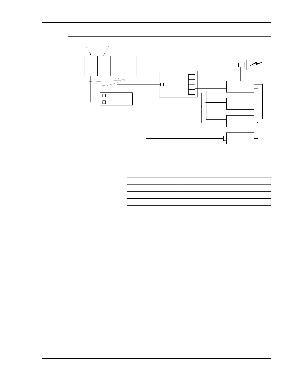
INSTALLATION
PRIMARY
SECONDARY
DSM05PPT
PPT
P1
NTMF01
P3
–
A1
NKTU01 CABLES
P1
NTDI01
RS232 (LINES 1-5, 8, 20)
+
–
A2
+
–
A3
+
–
A4
+
Figure 3-6. Redundant Transceiver
Table 3-9. INPPR01 Function Codes
SELECT
ENABLE
ENABLE
ANTENNA
SWITCH
PRIMARY
TRANSCEIVER
REDUNDANT
TRANSCEIVER
MODEM
T00421A
Function Code Title
FC 127 Plant Loop Gateway Node Map
FC 130 Plant Loop Gateway Executive
FC 131 Plant Loop Gateway Point Definition
INTERFACE CONFIGURATION
I-E96-624A 3 - 13
Page 34

SECTION 4 - OPERATING PROCEDURES
INTRODUCTION
This section explains how to place the INPPR01 in operation It
covers faceplate LEDs, modes of operation, and the two control
types. Additionally, it provides information concerning redundant operation and interface memory utilization.
PLANT LOOP TO PLANT LOOP TRANSFER MODULE LEDs AND CONTROLS
The faceplate of the PPT has the following components (see Figure 4-1):
1. Status LED
2. 8 CPU LEDs
3. 2 Memory Status LEDs
4. Stop pushbutton
5. Reset pushbutton
INPPT01
STATUS LED
1
2
3
4
CPU
5
6
7
8
STOP
RESET
PUSHBUT TON
Figure 4-1. PPT Faceplate LEDs
1
MEM
2
T00422A
INTRODUCTION
I-E96-624A 4 - 1
Page 35

OPERATING PROCEDURES
Status LED
The Status LED is a red/green LED that displays the operating
status of the PPT. It has five possible states. Table 4-1 lists the
meaning of the status LED states. Refer to Section 5 for corrective action if the status LED indicates that an operating error
exists.
Table 4-1. PPT Status LED States
LED State Meaning
Off No power to the PPT.
Solid Green The PPT is in the EXECUTE Mode.
Flashing Green (once per second) The PPT is in the EXECUTE M ode and d etects a NVM checksum
error.
Flashing Green (4 times per second) The PPT is in the CONFIGURE or ERROR Mode.
Solid Red The PPT diagnostics detect a hardware failure or configuration
problem. CPU LEDs displ ay an error co de when the status LED
is red.
®
CPU LEDs
Memory LEDs
Stop Pushbutton
During normal operation, the CPU LEDs keep a count of the
internal and external messages that pass through the PPT. If a
communication error occurs, these LEDs display an error code
and the Status LED turns RED. Refer to Table 5-1 for a list of
CPU LED error codes and corrective action.
There are two Memory LEDs. MEM LED 2 is on while the module is correcting single bit errors. Both LEDs are on when a
two-bit error or a complete memory failure occurs.
Push the stop pushbutton before removing a PPT from the
Module Mounting Unit. The stop pushbutton causes the following actions to occur:
1. Allows any NVM write in progress to complete.
2. Forces control from a primary to a secondary PPT in redundant configurations.
Reset Pushbutton
Pressing the reset pushbutton causes:
1. Restoration of PPT to power-up values after a halt.
PLANT LOOP TO PLANT LOOP TRANSFER MODULE LEDs AND CONTROLS
4 - 2 I-E96-624A
Page 36

2. Recovery from an operator-initiated stop or a module
timeout.
LOOP INTERFACE MODULE LEDs
There are eight LEDs on the LIM faceplate (see Figure 4-2).
These LEDs display the contents of event and error counters,
and pass/fail information when on-board diagnostics are run
(refer to Tables 3-4 and 3-5 for a list of event and error counter
codes).
OPERATING PROCEDURES
INLIM03
1
2
3
4
5
6
7
8
T00399A
Figure 4-2. LIM Faceplate LEDs
BUS TRANSFER MODULE LED
The Bus Transfer Module has one red/green LED that displays
the module's operating condition (see Figure 4-3). The BTM
Status LED has three possible states. Refer to Table 4-2 for
BTM Status LED states and their meaning. Section 5 explains
the corrective action to take if the Status LED displays a BTM
hardware failure.
MODES OF OPERATION
The Plant Loop-to-Plant Loop Remote Interface has three
modes of operation: Configure, Execute and Error. Within the
Execute mode the module has two methods of control: one-way
or two-way control.
LOOP INTERFACE MODULE LEDs
I-E96-624A 4 - 3
Page 37

OPERATING PROCEDURES
®
INBTM01
STATUS LED
Configure Mode
Execute Mode
T00413A
Figure 4-3. BTM Faceplate LEDs
Table 4-2. BTM Status LEDs States
LED States Meaning
Off No power to th e BTM.
Solid Green Normal Operation.
Solid Red BTM hardware failure.
This mode applies to the INPPT01 module. Module configuration requires an INFI 90 operator interface device (i.e., Operator Interface Station, Management Command System,
Engineering Work Station, etc.). Refer to Section 3 and to the
instruction for your operator interface device for information
about interface configuration.
This is the normal mode of operation for the PPR. In the execute mode, the PPR issues requests for exception reports (XRs)
twice a second, collects XRs, exercises control (local to remote),
allows the operator to adjust tunable module specifications
and configure modules in remote loops. The interface enters
one of the two control types that the user configures during
installation.
MODES OF OPERATION
4 - 4 I-E96-624A
Page 38

Error Mode
One-Way Control
OPERATING PROCEDURES
The PPT enters this mode if the built-in system diagnostics
detect a hardware or configuration error. If the PPT detects a
hardware error, the module halts and displays an error code on
the CPU LEDs. If the CPU LEDs display a configuration error,
the module remains in the error mode. Refer to Section 5 for
corrective action when the PPT enters the error mode.
The PPT option switch setting (set during installation) determines if the module is in one-way control. In one-way control,
the local Plant Loop requests XRs from all remotes twice a second. The operator does module tuning and configuration, and
issues control commands to the remote Plant Loops through
the operator interface.
This type of control requires only one serial port (port 0). Port 1
can also be used as an additional link through which the local
loop issues commands. Using both ports increases the total
throughput of the PPT (see Figure 4-4).
PCU
4
OIS
1
REMOTE
PLANTLOOP
A
PPR
10
SERIALPORT 0
LEGEND:
OIS = OPERATOR INTERFACESTATION
PCI = PLANT LOOP TO COMPUTER
INTERFACE
PCU = PROCESS CONTROL UNIT
PPR = PLANT LOOP TO PLANT LOOP
REMOTE INTERFACE
PCU
PCU
1
PCU
20
2
LOCAL PLANT LOOP
SERIAL PORT
PPR
10
PCU
1
REMOTE
PLANT LOOP
B
PPR
10
SERIALPORT 1
PCU
4
PCU
10
PCI
33
OIS
30
OIS
20
T00423A
Figure 4-4. Local Plant Loop Using Both Serial Ports in One-Way
Control
MODES OF OPERATION
I-E96-624A 4 - 5
Page 39

OPERATING PROCEDURES
Two-Way Control
In two-way control, bidirectional communication requires both
ports on both Plant Loops (Port 0 to Port 0; Port 1 to Port 1).
Both loop interfaces can issue requests, control commands
and do module tuning and configuration. The local interface
uses one serial port to issue commands and receive replies (see
Figure 4-5). The remote interface uses the other port for the
same purpose. As in one-way control, the PPT requests XRs
twice a second; control and configuration commands are
through operator action.
REDUNDANT INTERFACE OPERATION
Redundant interface configurations require two sets of LIM/
BTM and PPT modules. Each set of modules reside on a separate module bus. Redundant interfaces share a common slave
expander bus. Upon start-up, one interface assumes the primary role; the other waits in a backup role. The primary PPT
®
PCU
1
OIS
1
PPR
PPR
LOCAL
PLANTLOOP
OIS
2
PCU
4
REMOTE
PLANTLOOP
10
SERIAL PORTS
LOCAL XMIT/RCVREMOTE XMIT/RCV
SERIAL PORTS
10
PCU
4
PCU
20
T00424A
Figure 4-5. Local and Remote Plant Loops in Two-Way Control
REDUNDANT INTERFACE OPERATION
4 - 6 I-E96-624A
Page 40

downloads the interface configuration to the secondary (redundant modules are identically configured to their primary counterpart). If the primary interface fails, the redundant unit takes
over and re-establishes the point data.
INTERFACE POINT CAPACITY
There are three factors that determine the maximum number
of points in a PPT configuration. Those factors are: point type
(exception report data type), the number of devices that receive
interface generated exception reports and the total memory
available (440,000 bytes). Table 4-3 lists the required memory
bytes for all point types when memory usage is for:
1. The local PPT receiving points from the remote PPT.
2. The remote PPT (in two-way mode) receiving points from
the local PPT.
OPERATING PROCEDURES
Table 4-3. Memory Usage in Receiving Communication
Point Type
Digital 16
Analog 30
Station 76
Remote Control Memory (RCM) 22
Remote Manual Set Constant (RMSC) 38
Device Driver 22
Add 6 bytes per point per destination being sent.
NOTE:
Memory Bytes
Required
Table 4-4 lists the required memory bytes for all point types
when the memory usage is for:
1. The remote PPT sending points to the local PPT.
2. The local PPT (in two-way mode) sending points to the
remote PPT.
NOTE:
The PPT has a capacity of 5,000 blocks.
INTERFACE POINT CAPACITY
I-E96-624A 4 - 7
Page 41

OPERATING PROCEDURES
Digital 18
Analog 22
Station 70
Remote Control Memory(RCM) 22
Remote Manual Set Constant (RMSC) 26
Device Driver 22
NOTE:
that sources Exception Reports.
MEMORY USAGE EXAMPLE
In this example, a pair of interfaces in one-way mode has the
following mix of points in their configuration:
500 digital points (S3 of FC131 = 0)
200 analog points (S3 of FC131 = 1)
50 stations (S3 of FC131 = 2)
®
Table 4-4. Memory Usage in Sending Communication
Point Type Memory Bytes Required
Add 16 byte s fo r ea ch PCU th at sou rc es Ex cept ion R epo rts. Ad d 10 by te s fo r eac h mod ul e
Distribution of 750 total points on the remote loop is among 20
modules residing in 10 different PCUs. There are five OISs on
the local loop. Each OIS receives all of the points.
Memory Usage in the Local PPT
The points are coming to the local from the remote, therefore,
Table 4-3 applies. The calculations are:
500 digital points x 16 bytes/point = 8,000 bytes
200 analog points x 30 bytes/point = 6,000 bytes
50 station points x 76 bytes/point = 3,800 bytes
Each OIS receives all 750 points:
5 OIS x 750 points x 6 bytes/point = 22,500 bytes
Total memory used in the local PPT = 40,300 bytes
Memory Usage in the Remote PPT
These points are to be sent to the local, therefore, Table 4-4
applies. The calculations are:
500 digital points x 18 bytes/point = 9,000 bytes
200 analog points x 22 bytes/point = 4,400 bytes
50 station points x 70 bytes/point = 3,500 bytes
20 modules x 10 bytes/module = 200 bytes
10 PCUs x 16 bytes/PCU = 160 bytes
Total memory used in the remote PPT = 17,260 bytes
MEMORY USAGE EXAMPLE
4 - 8 I-E96-624A
Page 42

SECURITY FUNCTIONS
Hardware Checks
Software Checks
OPERATING PROCEDURES
The PPT performs both hardware and software security checks
to insure module integrity.
The PPT does the following hardware checks:
1. Error Detection and Correction - Detects single bit and
double bit errors in the dynamic RAM. Corrects single bit
errors; halts PPT operation on double bit errors.
2. Illegal Address Detection - Detecting an illegal address generates a bus error and the PPT halts operation.
3. Machine Fault Timer - The microprocessor updates this
timer. A machine fault timeout halts module operation.
Utilities
The PPT does the following software checks:
1. Module Diagnostics - Module diagnostics execute automatically on system power up. PPT faceplate LEDs display error
conditions if the diagnostic tests fail.
2. Module Status Check - This test verifies checksums of the
UVROM and NVM. Discrepancies cause the PPT Status LED to
flash green and PPT operation halts.
The utilities menu shown in Figure 4-6 is available to the user
by attaching a diagnostic monitor to serial port 1. Items 1, 4
and 5 are used for Bailey Engineering purposes. Items 2 and 3
are available to the user.
When 2 is keyed in, the following appears:
2 - Which Loop?
reply: not configured or
communicating or
communication failed, will retry in x seconds
When 3 is keyed in, the following appears:
3 - Enter Slave Address:
enter new digital outputs:
reply 0 or 1
SECURITY FUNCTIONS
I-E96-624A 4 - 9
Page 43

OPERATING PROCEDURES
PPT UTILITIESM ENU,REVISION X.X
COPYRIGHT (C) 1990 B AILEY CONTROLS CO MPANY
1 DEBUG 2 LOOP C OMM. REPORT
3 DIGITAL OU TPUT TEST 4 CP U UTILIZATION
5READMEMORY
T00425A
Figure 4-6. PPT Utilities Menu
®
SECURITY FUNCTIONS
4 - 10 I-E96-624A
Page 44

INTRODUCTION
SECTION 5 - TROUBLESHOOTING
If errors occur while the interface is operating, the CPU LEDs
on the PPT faceplate display error codes. Table 5-1 lists the
error codes and corrective action.
NOTE:
Status LED is red. A 0 represents a LED that is off and a 1 represents a LED that is on.
Codes are displayed only when the PPT is halted and the
Table 5-1. Table 5-1. PPT Error Codes
LED
87654321
00000001 An error affecting the NVM checksum has
occurred.
00000010 An error occurred while the PPT was writing
to its non-volatile memory.
00000011 External communication equipment failure
detected.
00001011 Contact 7 of Option Switch U72 has been
set (NVM initialized).
00001100 NVM write in progress when power lost. None.
00001101 An error occurred in communication
between primary PPT and redundant PPT.
00001110 PPT redundancy switches (Option Switch
U72 contact 8) are the same.
00001111 Primary PPT failed before its configuration
was copied to the backup.
00010000 Secondary PPT loop address (U75) does
not match primary PPT.
00010001 Secondary PPT control mode or RS-232C
mode (DCE or DTE) or ID (local or remote)
does not match primary PPT.
00010010 BTM not responding. Replace the BTM.
00010011 ROM checksum error. Reset the PPT.
00110000 The system tried to force control to the
redundant PPT while the primary PPT was
still functioning.
00110001 A fault in either the CPU or MEM boards
exists.
00110010 An addressing error occurred on internal
microprocessor address bus.
00110011 Attempt to execute an illegal processor
instruction.
Meaning Corrective Action
None.
None.
Check the exter nal communica tion
equipment.
None.
None.
Set U72 (position 8) on secondary
PPT to 0 and U72 on the primary
PPT to 1.
Reset the secondary PPT and
enter the configuration.
Set secondary PPT loop address
to match the primary PPT loop
address.
Check the opti on switch settings
(U72) on the secondary PPT.
None.
Replace the PPT.
Reset the PPT.
Reset the PPT.
INTRODUCTION
I-E96-624A 5 - 1
Page 45

TROUBLESHOOTING
®
Table 5-1. Table 5-1. PPT Error Codes
LED
87654321
00110101 Microprocessor received spurious excep-
tion vector.
00110110 A divide by 0 or CHK instruction was
expected.
00110111 TRAP instruction was executed. None.
00111111 The PPT has stopped because the user
pressed the Stop pushbutton.
00000000
10000000
1. These codes apply to the secondary PPT in a redundant configuration.
1
The secondary PPT configuration is not
copied from the primary PPT yet.
1
The secondary PPT correct ly copi ed the p ri-
mary config uration and is ready to take
over.
Meaning Corrective Action
Status Bytes
Five status bytes provide information about Plant Loop to Plant
Loop Transfer Module status. These bytes are available
through any operator interface such as the Operator Interface
Station (OIS). Refer to the instruction for your operator interface for an explanation of how to access status bytes. Table 5-2
lists the status bytes. Table 5-3 lists the status byte
definitions.
(continued)
Reset the PPT.
Reset the PPT.
Reset the PPT.
None.
None.
Table 5-2. Status Bytes
Byte
1 ES MODE TYPE
2 FTX BAC RIO LIO N/A NVI CFG N/A
3 PCU MEM NEF N/A N/A N/A N/A N/A
4 LIE LRE LRE LTE LTE N/A N/A N/A
5 N/A N/A N/A N/A N/A N/A N/A N/A
76543210
Bit+
INTRODUCTION
5 - 2 I-E96-624A
Page 46

TROUBLESHOOTING
Table 5-3. Status Byte Definitions
Field Value Description
Byte 1
ES
MODE
TYPE
Byte 2
FTX
BAC
RIO
LIO
N/A
NVI
CFG
N/A
Byte 3
PCU
MEM
NEF
Bits 0-4
Byte 4
LIE
LRE
LRE
LTE
LTE
Bits 0-3
Byte 5
Bits 0-7 Not Applicable
80
60
1F
80
40
20
10
04
02
01
02
03
80
40
20
40
80
Error Summary (0-OK, 1-Error)
Module Mode (00-Config, 01-Error, 11-Exec)
Module Type Code = Hex 11 (INPPT01)
First Time in Execute (0-No, 1-Yes)
Backup PPT Status (0-OK, 1-Bad)
Summary Remote I/O Status (0-OK, 1-Bad)
Summary Local I/O Status (0-OK, 1-Bad)
Not Applicable
NVM Checksum Error (0-OK, 1-Bad)
Default Configuration (0-No, 1-Yes)
Not Applicable
One or more PCUs offline (0-No, 1-Yes)
Memory Full (0-No, 1-Yes)
Node Environment Failure (0-No, 1-Yes)
Not Applicable
LIM Internal Error
Loop Receive Error Channel 1
Loop Receive Error Channel 2
Loop Transmit Error Channel 1
Loop Receive Error Channel 2
Not Applicable
Table 5-4. LIM Edge Connector P3 Pin Assignments
Pin No. Signal Pin No. Signal
1 Loop 2 In (+) 13 Loop 2 Bypass Control
2 Loop 2 In (-) 14 Cable Shield
3 Cable Shield A Cable Shield
4 Loop 1 Out (+) D Loop 1 Out (-)
5 Loop 1 Out (+) E Loop 1 Out (-)
6 Loop 1 In (+) F Ca ble Shield
7 Loop 1 In (-) H Loop 2 Bypass Control
8 Cable Shield K Loop 2 Out (-)
9 Loop 2 Out (+) L Loop 2 Out (-)
10 Loop 2 Out (+) M Cable Shield
11 Cable Shield S Cable Shield
INTRODUCTION
I-E96-624A 5 - 3
Page 47

TROUBLESHOOTING
Table 5-5. BTM Edge Connector P1 Pin Assignments
Pin No. Signal Pin No. Signal
1 +5 VDC 2 +5 VDC
3N/C 4N/C
5 Common 6 Common
7 +15 VDC 8 -15 VDC
9 Power Fail Interrupt 10 Power Fail Interrupt
11 Module Bus 12 Module Bus
Table 5-6. PPT CPU Board Edge Connector P2 Pin Assignments
Pin No. Signal Pin No. Signal
1 Data Bit D1 2 Data Bit D0
3 Data Bit D3 4 Data Bit D2
5 Data Bit D5 6 Data Bit D4
7 Data Bit D7 8 Data Bit D6
9 Clock 10 Sync
11 N/C 12 N/C
All data bits are low true.
NOTE:
®
Table 5-7. PPT CPU Board Edge Connector P3
Pin Assignments
Pin No. Signal Pin No. Signal
1 SAC Link (+) A SAC Link (-)
2 Redundancy Link
Transmit Data (+)
3 Redundancy Link
Receive Data (-)
4 Terminal Port
Transmit Data
5 Terminal Port
Request to Send
6 Terminal Port
Data Carrier Detect
7 Printer Port
Transmit Data
8 Printer Port
Request to Send
9 Printer Port
Data Carrier Detect
B Redundancy Link
Transmit Data (-)
C Redundancy Link
Receive Data (+)
DTerminal Port
Receive Data
ETerminal Port
Clear to Send
FN/A
H Printer Port
Receive Data
J Printer Port
Clear to Send
KN/A
INTRODUCTION
5 - 4 I-E96-624A
Page 48

TROUBLESHOOTING
Table 5-7. PPT CPU Board Edge Connector P3
Pin Assignments
Pin No. Signal Pin No. Signal
10 Digital Output 1 (+) L Digital Output 1 (-)
11 Digital Output 2 (+) M Digital Output 2 (-)
12 N/A N N/A
13 N/A P N/A
14 N/A R N/A
15 N/A S N/A
(continued)
INTRODUCTION
I-E96-624A 5 - 5
Page 49

INTRODUCTION
SECTION 6 - MAINTENANCE
The Plant Loop to Plant Loop Remote Interface (INPPR01)
requires minimal maintenance. The following maintenance
schedule will ensure trouble free service.
MAINTENANCE SCHEDULE
NOTE:
Only qualified personnel should perform maintenance.
The PPR maintenance schedule is shown in Table 6-1. Perform
these tasks at the specified intervals.
Table 6-1. Maintenance Schedule
Task Interval
Clean and check all cable
connections to the INLIM03,
INBTM01 and INPPT01.
Use a static vacuum cleaner
to remove dust from:
Modules
Module Mounting Unit
Fan Assembly
Power Entry Panel
Every 6 months or during
plant shutdown, whichever
occurs first.
Every 6 months or during
plant shutdown, whichever
occurs first.
INTRODUCTION
I-E96-624A 6 - 1
Page 50

SECTION 7 - REPAIR/REPLACEMENT PROCEDURES
INTRODUCTION
This section explains the replacement procedures for the Plant
Loop to Plant Loop Remote Interface (INNPPR01). There are no
special tools required to replace an interface module.
NOTE:
when working with th e interf ace m odules . This kit co nnects the s tatic
dissipative work surface and technician to the same ground point.
MODULE REPAIR/REPLACEMENT
If you determine an interface module is faulty, replace it with a
new one. DO NOT try to repair the module; replacing components may affect the module performance. You can remove the
module while system power is supplied. To replace a module:
1. Press the stop pushbutton and wait for the status LED to
turn red.
2. Push and turn the two front panel captive latches one half
turn to unlatch the module. It is unlatched when the slots on
the latches are vertical and the open end of the slots face away
from the module.
3. Gently slide the module out of the MMU.
4. Configure the replacement module switch and jumper settings. Ensure they are set the same as the original module.
Always use the Bailey Field Static Kit (P/N 1948385A1)
5. In the same slot assignment as the original module, align
the replacement module with the guide rails in the MMU; gently slide it in until the front panel is flush with the top and bottom of the MMU frame.
6. Push and turn the two captive retaining latches on the
module faceplate one half turn to the latched position. It is
latched when the slots on the latches are vertical and the open
ends face the center of the module.
7. Return to normal operation.
INTRODUCTION
I-E96-624A 7 - 1
Page 51

SECTION 8 - SUPPORT SERVICES
INTRODUCTION
Bailey Controls is ready to assist in the use of its products.
Requests for sales, applications services, installation, repair,
overhaul and maintenance contract services should be made to
the nearest sales office.
REPLACEMENT PARTS AND ORDERING INFORMATION
If you are making repairs at your own facility, replacement
parts should be ordered through a Bailey sales office. Provide
the following information for parts orders:
1. Part description, part number and quantity.
2. Model, serial number (if applicable) and ratings of the
assembly containing the ordered part.
3. Bailey publication number and reference used in identifying the part.
When ordering standard parts from Bailey Controls, use the
part number and description from the Replacement Parts section of the manual. Parts not having a commercial description
in the Replacement Parts section must be ordered from a
Bailey Controls sales office.
TRAINING
Bailey Controls has a modern training facility equipped to provide service and repair instructions. This facility is available for
in-plant training of your personnel. Contact a Bailey Controls
sales office for information on available classes and scheduling.
TECHNICAL DOCUMENTATION
You can obtain additional copies of this manual through the
nearest Bailey sales office. Copies, over and above those provided with the original purchase, are available at a minimum
charge to the customer. Contact a Bailey Controls sales office
for information.
INTRODUCTION
I-E96-624A 8 - 1
Page 52

APPENDIX A - TERMINATION UNIT CONFIGURATION
P1 CONN ECTOR
STATION
COMMUNICATION
P2 CONN ECTOR
TERMINAL
PORT
PRINTER
PORT
PORT
1
PORT
0
F1 FUSE
+24 V (E2)
COM (E 3)
T00426A
P3
CONNECTOR
XU1
XU2
P5
P6
XU4
XU4
XU2
XU3
XU3
XU1
+24 VDC
+24 VDC
RXD
RXD
RXD
RXD
RTS
RTS
RTS
RTS
CTS
CTS
CTS
CTS
TXD
TXD
TXD
TXD
DCD
DCD
1
1
CABLE
SHIELDING
GROUND
CABLE
SHIELDING
GROUND
DB-25 PIN
ASSIGNMENT
DB-25 PIN
ASSIGNMENT
3
3
4
4
5
5
2
2
1
7
9
8
6
2
5
4
3
10
1
7
9
8
6
2
5
4
3
10
1
7
9
8
6
2
5
4
3
10
1
7
9
8
6
2
5
4
3
10
20
14
12
13
15
19
16
17
18
11
20
14
12
13
15
19
16
17
18
11
20
14
12
13
15
19
16
17
18
11
20
14
12
13
15
19
16
17
18
11
LOCAL AND REMOTE
(NTMF01)
INTRODUCTION
The INPPT01 uses the NTMF01 for termination. Figure A-1
shows the dipshunt configuration required when connecting a
local and remote PPT (DTE) via a modem (DCE). Figure A-2 and
A-3 show the dipshunt configuration required when directly
connecting a local PPT (DTE) to a remote PPT (DCE) via a cable.
Figure A-4 shows how to configure the dispshunts so that port
1 can drive a diagnostics terminal. Figure A-5 shows the
RS-232-C signals and the associated DB-25 pin assignments.
Figure A-1. Disphunt Configuration for PPT Acting as DTE (Requires Modem or Other DCE)
I-E96-624A A - 1
INTRODUCTION
Page 53

TERMINATION UNIT CONFIGURATION (NTMF01)
P5
TERMINAL
PORT
PRINTER
PORT
P6
P1 CONN ECTOR
STATION
COMMUNICATION
P2 CONN ECTOR
F1 FUSE
+24 V (E2)
COM (E 3)
XU1
XU2
XU3
XU4
P3
CONNECTOR
XU1
XU2
XU3
XU4
DCD
CTS
RTS
RXD
TXD
DCD
CTS
RTS
RXD
TXD
®
LOCAL
+24 VDC
1
20
2
19
3
18
4
17
5
16
6
15
7
14
8
13
9
12
10
1
2
3
4
5
6
7
8
9
10
1
2
3
4
5
6
7
8
9
10
1
2
3
4
5
6
7
8
9
10
CABLE
11
SHIELDING
20
GROUND
19
1
18
17
16
15
14
13
12
11
20
19
18
17
16
15
14
13
12
11
20
19
18
17
16
15
14
13
12
11
CTS
RTS
RXD
TXD
CTS
RTS
RXD
TXD
DB-25 PIN
ASSIGNMENT
5
4
3
2
+24 VDC
CABLE
SHIELDING
GROUND
1
DB-25 PIN
ASSIGNMENT
5
4
3
2
PORT
0
PORT
1
T00427A
Figure A-2. Dipshunt Configuration for Direct Connection with Local PPT Acting as DTE
INTRODUCTION
A - 2 I-E96-624A
Page 54

TERMINATION UNIT CONFIGURATION (NTMF01)
P1 CONN ECTOR
STATION
COMMUNICATION
P2 CONN ECTOR
TERMINAL
PORT
PRINTER
PORT
PORT
0
PORT
1
F1 FUSE
+24 V (E2)
COM (E 3)
T00428A
P3
CONNECTOR
XU1
XU2
P5
P6
XU4
XU2
XU4
XU3
XU1
XU3
+24 VDC
+24 VDC
RTS
RTS
RXD
RXD
TXD
TXD
CTS
CTS
DCD
DCD
RXD
RXD
TXD
TXD
CTS
CTS
RTS
RTS
1
1
CABLE
SHIELDING
GROUND
CABLE
SHIELDING
GROUND
DB-25 PIN
ASSIGNMENT
DB-25 PIN
ASSIGNMENT
4
4
3
3
2
2
5
5
1
7
9
8
6
2
5
4
3
10
1
7
9
8
6
2
5
4
3
10
1
7
9
8
6
2
5
4
3
10
1
7
9
8
6
2
5
4
3
10
20
14
12
13
15
19
16
17
18
11
20
14
12
13
15
19
16
17
18
11
20
14
12
13
15
19
16
17
18
11
20
14
12
13
15
19
16
17
18
11
REMOTE
Figure A-3. Dipshunt Configuration for Direct Connection with Remote PPT Acting as DCE
I-E96-624A A - 3
INTRODUCTION
Page 55

TERMINATION UNIT CONFIGURATION (NTMF01)
®
P1 CONN ECTOR
STATION
COMMUNICATION
P2 CONN ECTOR
F1 FUSE
+24 V (E2)
COM (E 3)
Figure A-4. Dipshunt Configuration for Diagnostic Terminal (Port 1 only)
P3
CONNECTOR
XU1
XU2
XU3
XU4
P5
P6
TERMINAL
PORT
PRINTER
PORT
LOCAL OR REMOTE
DCD
1
RXD
2
TXD
3
4
CTS
DCD
CTS
5
6
7
8
9
10
1
2
3
4
5
6
7
8
9
10
XU3
XU4
+24 VDC
20
TXD
19
2
RXD
18
3
17
16
15
14
13
9
12
11
20
19
18
17
16
DCD
15
8
CTS
14
5
13
12
11
PORT 1
ONLY FOR
DIAGNOSTIC
TERMINAL
T00429A
INTRODUCTION
A - 4 I-E96-624A
Page 56

TERMINATION UNIT CONFIGURATION (NTMF01)
TXD
RXD
RTS REQUEST TO SEND
CTS
DCD
DCD
RXD
TXD
CTS
RTS
CTS
CTS
CTS
RTS
CTS
DCD
CTS
RTS
RXD
TXD
TRANSMIT DATA
RECEIVE DATA
CLEARTO SEND
RECEIVED LINE SIGNAL DETECT
+24V
DTE
1
2
3
4
5
6
7
8
9
10
1
2
3
4
5
6
7
8
9
10
XU1
XU3
XU2
XU4
20
19
18
17
16
15
14
13
12
11
20
19
18
17
16
15
14
13
12
11
TD
2 TRANSMIT DATA
RD
3 RECEIVE DATA
RTS
4 RE Q UE ST TO SE ND
CTS
5 CLEAR TO SEND
DCD
8 RECEIVED LINE SIGNAL DETECT
SDCE
9+VOLTS
12 SECONDARY RECEIVE SIGNAL DETECT
SRD
16 SECONDARY RECEIVE SIGNAL
25 BUSY
1 PROTECTIVE GROUND
DTR
20 DATATERM INAL READY
DSR
6 DATA SET READY
7 SIGNAL GROUND
DCE
22 RING DETECT
STD
14 SECONDARY T RANSMITTED DATA
QM
11 EQUALIZER MO DE
Figure A-5. DB-25 Pin Assignments and RS-232-C Signals
T00375A
INTRODUCTION
I-E96-624A A - 5
Page 57

APPENDIX B - TERMINATION UNIT CONFIGURATION
(NTCL01)
INTRODUCTION
The INLIM03 uses the NTCL01 for termination. Table B-1 lists
the terminal assignments and Table B-2 lists the BNC terminal
assignments for the loop input/output connections. Table B-3
provides jumper settings associated with cable type. Figure B-1
shows twinax cable connections for the NTCL01.
NOTE:
nect to the BNC connectors.
Twinax cables connect to the terminals. Coax cables con-
Table B-1. NTCL01 Terminal Assignments
Terminal
Number
TB1
1
2
3
4
5
6
7
8
Assignments
Loop 1 In, +
Loop 1 In, Loop 1 In, Shield
no connection
Loop 1 Out, +
Loop 1 Out, Loop 1 Out, Shield
Power System Status 1
Table B-2. BNC Terminal Assignments
BNC
Number
J1
J2
Assignments
Loop 1 In
Loop 1 Out
Terminal
Number
TB3
1
2
3
4
5
6
7
8
BNC
Number
J8
J9
Assignments
Loop 2 In, +
Loop 2 In, Loop 2 In, Shield
no connection
Loop 2 Out, +
Loop 2 Out, Loop 2 Out, Shield
Power System Status 2
Assignments
Loop 2 In
Loop 2 Out
INTRODUCTION
I-E96-624A B - 1
Page 58

TERMINATION UNIT CONFIGURATION (NTCL01)
Table B-3. Jumper Settings and Cable Types
®
NLIM03
NLIM03 - PLANT LOOP
JUMPER NO.
J3, J10
J4-J7, J11-J14
J15-J18
P1
P3
P2
NKLS03 (NLIM03)
TWINAX COAX
123
POST
NUMBERS
NTCL01
P1
E2E2COM
E1E1+24V
NTCL01
P1
COM
+24V
TB2
TB1
TB2
TB1
LOOP2
J9
J8
87654321
87654321
J2
J1
LOOP1
LOOP2
J9
J8
87654321
SH- IN+
87654321
J2
J1
LOOP1
T00365A
NKPL01
T00366A
Figure B-1. NTCL01 Termination Unit and Terminal Assignments
INTRODUCTION
B - 2 I-E96-624A
Page 59
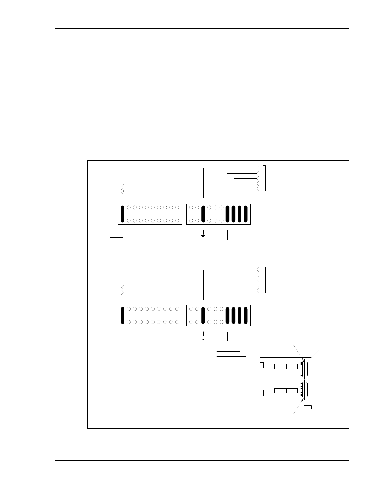
INTRODUCTION
APPENDIX C - TERMINATION MODULE
CONFIGURATION (NIMF01/NIMF02)
The INPPT01 can use the NIMF01 for termination. The NIMF02
is required when terminating redundant interfaces. The dispshunt configurations shown in Figure C-1 through C-4 apply
to the NIMF01 and NIMF02. Figure C-1 shows the dipshunt
configuration required when connecting a local and remote
PPT (DTE) via a modem (DCE). Figure C-2 and C-3 show the
dipshunt configuration required when directly connecting a
local PPT (DTE) to a remote PPT (DCE) via a cable.
+24 VDC
DCD
+24 VDC
DCD
CABLE SHIELDING GROUND
20
18
17
16
19
1
2
20
18
19
1
2
15
14
13
12
11
20
18
17
16
19
XU1
3
4
5
6
7
8
9
10
1
2
17
16
15
14
13
12
11
20
19
XU3
3
4
5
6
7
8
9
10
1
2
15
14
13
XU2
3
4
5
6
7
8
CTS
RTS
RXD
TXD
CABLE SHIELDING GROUND
18
17
16
15
14
13
XU4
3
4
5
6
7
8
CTS
RTS
RXD
TXD
12
9
12
9
1
CTS
5
RTS
RXD
TXD
11
DB-25 PIN
4
ASSIGNMENTS
3
2
PORT 0
10
1
CTS
5
RTS
RXD
TXD
11
DB-25 PIN
4
ASSIGNMENTS
3
2
PORT 1
10
TERMINAL PORT
XU1
LOCAL AND REMOTE
P1 EDGE
CONNECTOR
XU2
XU3
XU4
PRINTERPORT
PORT 0
PORT 1
T00430A
Figure C-1. Dipshunt Configuration for PPT Acting as DTE (requires Modem or Other DCE)
INTRODUCTION
I-E96-624A C - 1
Page 60

TERMINATION MODULE CONFIGURATION (NIMF01/NIMF02)
Figure C-3 shows how to configure the dispshunts so that port
1 can drive a diagnostics terminal.
®
+24VDC
DCD
+24VDC
CABLE SHIELDING GROUND
20
18
17
16
19
1
3
2
20
18
19
15
14
13
12
11
20
18
17
16
19
XU1
4
5
6
7
8
9
10
1
3
2
17
16
15
14
13
12
11
20
18
19
XU3
15
14
13
12
XU2
4
5
6
7
8
9
CTS
RTS
RXD
TXD
CABLE SHIELDING GROUND
17
16
15
14
13
12
XU4
1
CTS
5
RTS
RXD
TXD
11
DB-25 PIN
4
ASSIGNMENTS
3
2
PORT 0
10
1
CTS
5
RTS
RXD
TXD
11
DB-25 PIN
4
ASSIGNMENTS
3
2
PORT 1
1
3
4
5
2
DCD
6
7
8
LOCA L
9
10
1
3
4
5
CTS
RTS
RXD
TXD
6
7
8
9
10
TERMINAL PORT
XU1
P1 EDGE
CONNECTOR
XU3
XU2
XU4
PORT 0
PORT 1
2
PRINTER PORT
T00431A
Figure C-2. Dipshunt Configuration for Direct Connection of Local PPT Acting as DTE
INTRODUCTION
C - 2 I-E96-624A
Page 61

TERMINATION MODULE CONFIGURATION (NIMF01/NIMF02)
20118317416515
6
19
2
147138129111020118317416515
6
19
2
14713812911
2
3
4
1
5
10
+24 VDC
XU4
DCD
TXD
CABLE SHIELDING GROUND
RXD
RXD
TXD
CTS
RTS
RTS
CTS
XU3
DB-25 PIN
ASSIGNMENTS
PORT 1
20118317416515
6
19
2
147138129111020118317416515
6
19
2
14713812911
2
3
4
1
5
10
+24 VDC
XU2
DCD
TXD
CABLE SHIELDING GROUND
RXD
RXD
TXD
CTS
RTS
RTS
CTS
XU1
DB-25 PIN
ASSIGNMENTS
PORT 0
REMOTE
T00432A
TERMINAL PORT
PRINTER PORT
PORT 0
PORT 1
P1 EDGE
CONNECTOR
XU3
XU1
XU4
XU2
Figure C-3. Dipshunt Configuration for Direct Connection of Remote PPT Acting as DCE
INTRODUCTION
I-E96-624A C - 3
Page 62

TERMINATION MODULE CONFIGURATION (NIMF01/NIMF02)
®
+24 VDC
RXD
TXD
20118317416515
19
XU3
2
DIAGNOSTICTER MINAL
147138129111020118317416515
19
XU4
6
DCD
2
CTS
(PORT 1 ONLY )
14713812911
6
CONNECTOR
10
P1 EDGE
TXD
RXD
DCD
CTS
9
2
DB-25 PIN
3
ASSIGNMENTS
8
5
PORT1
TERMINAL PORT
XU3 XU4
PRINTER PORT
PORT 0
PORT 1
T00433A
Figure C-4. Dispshunt Configuration for Diagnostic Terminal
INTRODUCTION
C - 4 I-E96-624A
Page 63

INTRODUCTION
APPENDIX D - TERMINATION MODULE
CONFIGURATION (NICL01)
The INLIM03 can use the NICL01 for termination. Table D-1
lists the terminal assignments for the loop input/output connections. Table D-2 provides jumper settings associated with
cable type. Figure D-1 shows twinax cable connections for
NICL01.
NOTE:
nect to the BNC connectors.
Twinax cables connect to the terminals. Coax cables con-
CAUTION Ensure that the end marked J1 is connected to P1 on the
NICL01, and J2 is connected to the LIM. Failure to do so could
result in module damage (see Figure
D-1
).
ATTENTION S'assuree que L'extremite identifiee par J1 est reliee a P1 du
module NICL01 et que J2 est reliee au module LIM. Sinon, les
modules pouiraient etre endommages (voir la figure
Table D-1. NICL01 Terminal Assignments
TB1
Terminal
1
2
3
Assignments
Ground
Common
+24 VDC
TB2
Terminal
4
5
6
7
8
9
10
11
Assignments
Power System
Status 1
Power System
Status 2
Loop 2 In, +
Loop 2 In, Loop 2, Shield
Loop 2 Out, +
Loop 2 Out, Loop 2 Out, Shield
TB3
Terminal
25
26
27
28
29
30
31
32
Assignments
Loop 1 Out, Shield
Loop 1 Out, Loop 1 Out, +
Loop 1 In, Shield
Loop 1 In, Loop 1 In, +
no connection
no connection
D-1
).
Table D-2. BNC Assignments
BNC Number Assignments
J1
J2
J8
J9
Loop 1 In
Loop 1 Out
Loop 2 In
Loop 2 Out
INTRODUCTION
I-E96-624A D - 1
Page 64

TERMINATION MODULE CONFIGURATION (NICL01)
Table D-3. Jumper Settings and Cable Types
®
NLIM03
NLIM03 - PLANT LOOP
JUMPER NO.
J3, J10
J4-J7, J11-J14
J15-J18
P1
NKLS04
(NLIM03)J2 J1
P3 P1
P2
TWINAX COAX
123
POST
NUMBERS
TERMINAL 25 TO 28
NICL01
J1
J2
J9
J8
TB3
TB2
TB1
30
29
28
11
10
3
2
1
T00365A
26 TO 29
27 TO 30
NKPL01
NICL01
J1
J2
J9
J8
TB3
TB2
TB1
Figure D-1. Typical Twinax Cable Connection for the NICL01
27
26
25
11
10
3
2
1
T00396A
INTRODUCTION
D - 2 I-E96-624A
Page 65

Visit Elsag Bailey on the World Wide Web at http://www.bailey.com
Our worldwide staff of professionals is ready to meet
For the location nearest you, please contact the appropriate regional office.
AMERICAS
29801 Euclid Avenue
Wickliffe, Ohio USA 44092
Telephone 1-216-585-8500
Telefax 1-216-585-8756
ASIA/PACIFIC
152 Beach Road
Gateway East #20-04
Singapore 189721
Telephone 65-391-0800
EUROPE, AFRICA, MIDDLE EAST
Via Puccini 2
16154 Genoa, Italy
Telephone 39-10-6582-943
Telefax 39-10-6582-941
Telefax 65-292-9011
Form I-E96-624A Litho in U.S.A. 690
Copyright © 1990 by Elsag Bailey Process Automation, As An Unpublished Work
® Registered Trademark of Elsag Bailey Process Automation
™ Trademark of Elsag Bailey Process Automation
your
needs for process automation.
GERMANY
Graefstrasse 97
D-60487 Frankfurt Main
Germany
Telephone 49-69-799-0
Telefax 49-69-799-2406
 Loading...